Embed Size (px)
Citation preview

Computers and Mathematics with Applications 66 (2013) 2335–2343
Contents lists available at ScienceDirect
Computers and Mathematics with Applications
journal homepage: www.elsevier.com/locate/camwa
Back-propagating modes in elastic logging-while-drillingcollars and their effect on PML stabilityPaweł Jerzy Matuszyk a,b,∗, Carlos Torres-Verdín a
a Department of Petroleum and Geosystems Engineering, The University of Texas at Austin, TX 78712, USAb Department of Applied Computer Science and Modeling, AGH - University of Science and Technology, Kraków, Poland
a r t i c l e i n f o
Article history:Received 15 May 2013Received in revised form 5 September 2013Accepted 15 September 2013
Keywords:Perfectly matched layerBack-propagating modeAcoustic loggingBorehole acousticsWave propagationCoupled problems
a b s t r a c t
The Perfectly Matched Layer (PML) approach is widely used to implement the absorbingboundary conditions for coupled multi-physics wave propagation problems. However, ithas been recognized that the solution in the PML absorbing layer can become unstable inthe presence of back-propagatingmodes. This paper analyzes the spectral location of thosemodes excited by monopole acoustic sources in logging-while-drilling cylindrical tools. Torecover the stability of the solution for such a class of problems involving the modeling ofelastic cylindrical waveguides, we propose the implementation of artificial attenuation inthe waveguide to dampen undesirable modes, thereby making their amplitude negligiblein the PML absorbing layer due to the limited numerical accuracy and round-off errors.
© 2013 Elsevier Ltd. All rights reserved.
1. Introduction
Introduced by Bérenger [1] for electromagnetic (EM) wave propagation problem, the Perfectly Matched Layer (PML)technique is a standard method for truncating the computational domain and modeling radiation boundary conditions fornumerous wave propagation problems posed in the time and frequency domains and solved using numerical techniquessuch as finite-differences (FD) or finite elements (FE). The original method, relying on matching material conductivitiesand splitting the EM field components into subcomponents, was later reinterpreted by Chew and Weedon [2] through thecomplex coordinate stretching of the spatial variables of the original differential equations posed in the frequency domain,and subsequently in terms of an analytical continuation [3,4], which motivated the extension of the PML to curvilinearcoordinates and more general media. It is also possible to introduce such stretching directly in the weak form regardlessof the continuity class of the assumed field, which can significantly facilitate the derivation of the ultimate FE formulationincluding a PML absorbing layer [5]. Due to its generality, performance, and relatively simple implementation, it is currentlyalmost the only method used for truncation of coupled multi-physics problems.
Modeling of borehole sonic logging measurements falls into this class of problems: it involves the simultaneous solutionof wave propagation in a borehole fluid and surrounding elastic solid formation, possibly with anelastic attenuation. Themodel should also take into account the presence of a logging instrument in the borehole, which is modeled as an elasticcylindrical structure co-axial with the borehole. An important class of sonic logging measurements involves the so-calledlogging-while-drilling (LWD) technique, where the logging instrument is placed on amassive steel drilling collarwhilemea-surements are acquired during the drilling operation. The collar occupies a large portion of the borehole and substantially
∗ Corresponding author at: Department of Petroleum and Geosystems Engineering, The University of Texas at Austin, TX 78712, USA.E-mail addresses: [email protected], [email protected] (P.J. Matuszyk).
0898-1221/$ – see front matter© 2013 Elsevier Ltd. All rights reserved.http://dx.doi.org/10.1016/j.camwa.2013.09.012
2336 P.J. Matuszyk, C. Torres-Verdín / Computers and Mathematics with Applications 66 (2013) 2335–2343
affects wave propagation in the LWD environment, whereby the collar itself must be involved in any numerical simulationof sonic LWD measurements. An LWD collar is usually modeled as an elastic hollow cylinder, whose internal channel isfilled with a fluid. From the acoustic point of view, it plays the role of a waveguide for the waves generated by an acoustictransmitter, as well as for the noise generated by the drill bit.
Experience with the simulation of LWD sonic logging measurements in the frequency domain indicates that at somefrequencies the FE method does not produce a solution consistent with the physics of the problem due to instability causedby the PML. The PML method, with which we truncate the computational domain, assumes that the source is located in-side the domain, and all the excited waves are outgoing (i.e., they have positive phase velocities). By the construction of theabsorbing layer, all outgoing waves are exponentially attenuated, and all the incoming waves are exponentially amplifiedwithin the PML layer. The standard way to exclude the incoming waves from the solution is by imposing the homogeneousDirichlet boundary conditions at the outer boundary of the PML domain. The problem arises when waves with positive andnegative phase velocities coexist in the solution. In such a case, the PML attenuates one type of waves while amplifies theothers, destructively polluting the solution, thereby becoming non-physical. The classical example of the problem wheresuch a phenomenon exists is an elastic waveguide, e.g., Rayleigh–Lamb modes in plates [6], or analogous modes in circularrods [7] and cylindrical shells [8,9]. Similar unstable behavior of the PMLwas reported and investigated in detail by Bécacheet al. [10]when simulating the propagation of seismicwaves in anisotropicmedia. This phenomenonwas also reported in thefield of electromagnetic propagation [11] for ‘‘left-handed media’’ and waveguides. However, to the best of our knowledge,this problem has never been documented in the modeling of borehole sonic logging measurements.
Several approaches have been attempted to overcome PML instability. In [12], Skelton et al. proposed an implementationof two PMLs: the first absorbs forward- and the second—backward-propagating waves. This is possible owing to the simplegeometry and application of analytical orthogonality relations for Rayleigh–Lambmodes to separate incoming and outgoingwaves. Another approach, referred to as Multiaxial-PML (MPML), was presented in [13] by Meza-Fajardo and Papageorgiou,where damping profiles are specified simultaneously in many spatial directions (only one coordinate is stretched in theclassical PML), resulting in the stabilization of the problem for anisotropic media. In fact, the MPML method is a quasi-PMLmethod because the analytical continuation property is not valid anymore. The method works in Cartesian coordinates, butcannot be applied in cylindrical coordinates.
Herein, we propose to dampen the tool modes via visco-elastic attenuation in a collar to remove the instability of thePML. The tool mode that exhibits the undesirable behavior is very weak (small in amplitude) in comparison to the other toolmodes. Additional damping causes that the amplitude of that mode be significantly smaller and, provided that it is smallenough, it is not ‘‘seen’’ by the PML due to the limited numerical accuracy and round-off errors. It is important to observe thatsuch modification does not influence the excited formation modes, which we are most interested in when modeling soniclogging measurements. Furthermore, almost all modern LWD sonic logging instruments are carefully designed to highlyattenuate collar modes propagating between the transmitter and the array of receivers. This justifies the modeling of thecollar as an attenuating medium.
In the following, we first describe the governing equations and assumptions which lead to the final weak formulationfor the considered coupled wave propagation problem. Next, we analyze the LWD collar eigenmodes and identify the back-propagating modes. Then, we document numerical examples of simulations with undamped and attenuated collar modeswhich lead to non stable and stable solutions, respectively.
2. Problem formulation
The problem formulation and solution documented in this Section follows directly the method developed by Matuszyket al. [14,15], which is an extension of the method developed by Michler et al. [16]. The problem is solved in the frequencydomain using an automatically adaptive hp-finite element method [17,18].
We assume axial symmetry around the center of the borehole (see Fig. 1), allowing for arbitrary variations of materialproperties in the radial and axial directions. The interior part of the domain is typically composed of several concentric layersin order tomodelmandrel, borehole fluid, casing, cement, etc.Within the formation, one defines the horizontal layerswhich,in turn, can be further divided into rectangular blocks. Thus, one can model either the simple homogeneous formations orlayered heterogeneous formations that include local alteration zones, fluid-filled fractures, invasion, etc. Each subdomaincan be modeled either as a (visco-)acoustic fluid (ΩA), or as an isotropic or transversely isotropic (an)elastic solid (ΩE).
Acoustic fluid: propagation of acoustic waves in the fluid can be described as a perturbation of pressure and velocity arounda hydrostatic equilibrium state [19], and thus expressed by two coupled equations (continuity and linear momentum laws)posed in the frequency domain as:
iωp + c2f ρf ∇ · v = 0iωρf v + ∇p = 0,
(1)
where i =√
−1,ω denotes angular frequency, p(x, ω) is the (perturbation of) pressure, v(x, ω) denotes the fluid velocity, ρfis the fluid density, and cf stands for the fluid sound speed. The system of equations must be accompanied with appropriateboundary and, in the case of an unbounded domain, radiation conditions.

P.J. Matuszyk, C. Torres-Verdín / Computers and Mathematics with Applications 66 (2013) 2335–2343 2337
Fig. 1. Two-dimensional axially-symmetric geometry of the borehole environment assumed in the numerical simulation considered in this paper. Thereis a centered LWD collar inside the borehole. The outermost segment is an absorbing PML layer; Rb is borehole radius, Rin and Rout are inner and outer collarradius, respectively, and TX identifies the location of the acoustic transmitter.
Elastic solid: in the absence of body forces, elastic wave propagation in the formation and the tool can be described by thefollowing equations to be satisfied in the elastic domain ΩE :
−∇ · σ − ρsω2u = 0
σ = C : ε
ε(u) =12
∇u + ∇
Tu.
(2)
Here σ stands for the stress tensor, ε is the strain tensor, u denotes the displacement vector (all understood as theFourier transforms of the appropriate quantities), ρs is the solid density, and C denotes the elastic (Cijkl ∈ R or C if weassume attenuation) 4th-order compliance tensor. Analogously, the above equationsmust be accompaniedwith appropriateboundary and radiation conditions. For a linear isotropic solid, the tensor C simplifies to
Cijkl = µ(δikδjl + δilδjk) + λδijδkl,
where λ and µ denote (real) Lamé’s coefficients, which can be defined through characteristic wave speeds in the solid,namely: P-wave speed cP , and S-wave speed cS ,
µ = ρsc2S λ = ρs(c2P − 2c2S ). (3)
The equations are associated with two types of boundary conditions: homogeneous displacement (Dirichlet) boundarycondition (BC) imposed on part of the boundary ΓED ⊂ ΓE , ΓE = ∂ΩE , and (Neumann) tractions BC ns · σ = t prescribed onthe remaining part of the boundary ΓEN = ΓE − ΓED. Here ns stands for the outward unit normal vector to boundary ΓE .Coupling conditions: at the interface between fluid and solid, we impose the continuity of displacements, i.e. the equality ofthe normal component of velocities, and tractions, namely,
nf · ∇p = ρf ω2nf · u,
ns · σ = −nsp,
where nf denotes the outward unit normal vector to boundary ΓA.Attenuation: visco-acoustic and anelastic damping is introduced into the formulation through the application of the Aki–Richard’s model [20], where we invoke complex-domain velocities according to the equation
c(ω) = c0
1 +
1πQ
lnω
ω0
1 +
i2Q
, (4)
with c being complex-valued velocity, i =√
−1, c0 is a reference velocity at angular frequency ω0, and Q is an appropriatequality factor, associated with the velocity c0. The parameters defining the solid (Lamé’s parameters or six components of

2338 P.J. Matuszyk, C. Torres-Verdín / Computers and Mathematics with Applications 66 (2013) 2335–2343
the compliance tensor C for transversely-isotropic materials) are defined through the characteristic wave velocities in thesolid, and thus they become complex-valued.
Weak form: the weak form (FE formulation) of the coupled problem reads as follows:Find (p,u) ∈ (pD,uD) + W × Q such that for all q ∈ Q and allw ∈ W(∇p, ∇q)ΩA
−k2f p, q
ΩA
− ω2 ρf q,nf · uΓI
= ⟨q, gex⟩Γex
(ε(w), Cε(u))ΩE − ω2 (ρsw,u)ΩE+ ⟨ns · w, p⟩ΓI
= 0,(5)
where kf = ω/cf is wavenumber in the fluid and gex is the excitation data. Parentheses denote standard L2 inner-products (integrals) defined in the acoustic or elastic domains, whereas angle brackets denote duality pairings (integrals)on appropriate boundaries. The two boundary integrals defined on ΓI express the weak coupling occurring between theacoustic and elastic domains. Detailed descriptions of the weak formulation presented here can be found in [14].
PML formulation: we use the PML method to truncate the computational domain and impose the radiation boundaryconditions in the radial and axial directions. Using the technique developed by Matuszyk and Demkowicz [5], we directlymodify the weak form given in Eq. (5). First, we define the complex valued PML stretching of the coordinates
r(r, k) = r + g(r, k)(1 − i), (6)z(z, k) = z + g(z, k)(1 − i),
where i =√
−1 and the function g(x, k) is given by
g(x, k) =2p
kξ ′
|ξ ′|ξm, where ξ(x) =
xLj − x
δjx < xLj
x − xRjδj
xj > xRj0 otherwise,
(7)
and where the computational domain in the xj-direction is contained in [xLj − δj, xRj + δj], xLj < xRj , where δj is the PML widthin xj-direction, and parameter p controls the strength of wave attenuation.
Simultaneous stretching of both real and imaginary parts affects not only the plane waves but also the evanescent wavesare dampedwithin the PML region. The transformation of coordinates results in the analytic continuation of the solution intoa complex plane characterized by an exponential decay of outgoing waves, and an exponential blow-up of incoming wavesin the stretched direction within the PML absorbing region. Consequently, imposing a homogeneous Dirichlet boundary atthe end of the PML region does not affect the (‘‘stretched’’) outgoing wave but it eliminates the incoming one. It is of utmostpractical importance to construct the stretching in such a way that the attenuated outgoing wave reaches a computer zeroat the PML outer boundary.
Next, we define the PML Jacobian matrix as
J =∂ xi
∂xjai ⊗ aj =
r ′ 0 00 r/r 00 0 z ′
ei ⊗ ej. (8)
Here, xi are standard cylindrical coordinates, and xi their complex counterparts given by Eqs. (6), and ei are standard unitcovariant basis vectors in cylindrical coordinates. Additionally, we introduce a PML stretching Jacobian J = det(J) andmatrixA = JJ−1J−T . With the above definitions, we transform the weak form 5 and obtain
Find (p,u) ∈ (pD,uD) + W × Q such that for all q ∈ Q and allw ∈ WA∇p, ∇q
ΩA
−
k2f Jp, q
ΩA
− ω2ρf Jq,nf · u
ΓI
=
Jq, gex
Γex
ε(w),Cε(u)ΩE
− ω2ρs Jw,u
ΩE
+
Jns · w, p
ΓI
= 0,(9)
whereC is the fourth-order PML-stretched elastic tensor given by the equation
Cipkq = J J−1pj J−1
ql Cijkl. (10)
The coupled system given by Eq. (9) is solved using the multi-physics automatic hp-adaptive FE algorithm describedin detail in the previous publications [14,5]. We use the same PML parameterization as shown in [14]. In all the modelsconsidered in the paper, we stop the calculations when the relative error on the coarse mesh is below 0.5%. After that, weperform a global hp-refinement step and solve the final problem on the fine mesh, where the relative error is expected tobe lower than 0.1%.

P.J. Matuszyk, C. Torres-Verdín / Computers and Mathematics with Applications 66 (2013) 2335–2343 2339
Table 1Summary of the assumed material and geometrical properties of the LWD collars: internal/external radius,compressional and shear velocities and slownesses, Poisson ratio, and density.
Tool Rin (cm) Rout (cm) cP (m/s) sP (µs/ft) cS (m/s) sS (µs/ft) ν ρ (g/cm3)
T1 2.54 8.5725 5860 52.0 3130 97.4 0.300 7.85T2 2.54 8.5725 5860 52.0 2519 121.0 0.387 7.85T3 2.54 10.795 5860 52.0 3130 97.4 0.300 7.85T4 2.54 10.795 5860 52.0 2519 121.0 0.387 7.85
Table 2Material properties assumed in the simulation of LWD sonic waveforms acquired ina cased borehole: compressional and shear velocities and slownesses, and density.
Material cP (m/s) sP (µs/ft) cS (m/s) sS (µs/ft) ρ (g/cm3)
Fluid 1524 200 – – 1.10Fast form. 4354 70 2620 115 2.30
3. Back-propagating modes in the LWD tool and their effect on PML performance
The back-propagating mode is a mode whose phase and group velocities have opposite signs. One can readily detectthe presence and frequency location of the back-propagating mode via the inspection of dispersion curves associated withpropagating modes. The dispersion curves for cylindrical shells can be calculated in two ways. The first method attempts tosolve the nonlinear transcendental equation originating from the assumed analytical solution in the shell and imposed free-stress boundary conditions; the roots of this equations are complex axial wavenumbers related to the propagating modes[8,9]. The second approach involves the pseudospectral method with a Chebyshev approximation formulated for the samegoverning equations and boundary conditions [21,22]. In this latter case, the need of calculating Bessel functions (necessarilyapproximated) is eliminated at the expense of solving a generalized eigenvalue problem for each discrete frequency,whereinthe resulting eigenvalues are squares of the modes’ axial wavenumbers.
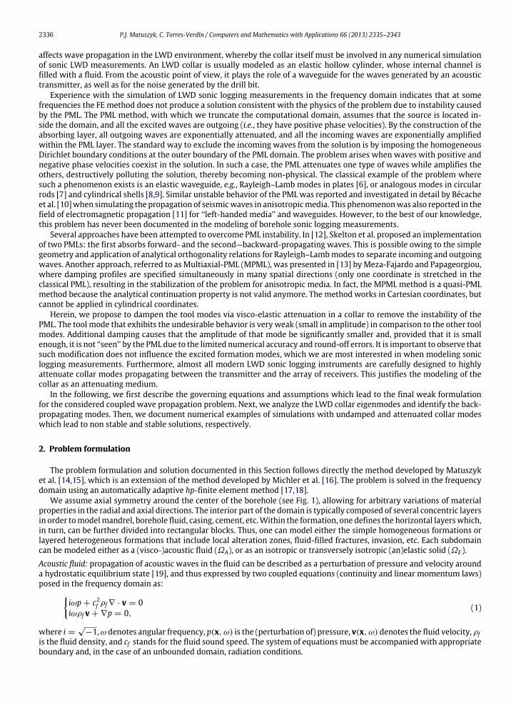
Fig. 2 shows the propagating modes excited in an LWD collar in the frequency-slowness (ω-s) and wavenumber–frequency (k-ω) domains, assuming material and geometric properties of the tool T4 (given in Table 1). Inspection of thefrequency range 0–30 kHz, indicates the existence of one back-propagating mode excited by a monopole acoustic source. InFig. 2(d), the back-propagating mode is identified by the dispersion curve with a negative slope (between 13 and 14 kHz),which indicates that its group velocity vg = dω/ dk is negative. Such an abnormal condition indicates that the back-propagating mode’s group and phase velocities have opposite signs, see [6]. Consequently, this behavior implies a nega-tive phase velocity (and positive group velocity) of the mode, as the energy is propagated away from the source, and inconsequence, catastrophic amplification of the mode in the PML absorbing layer occurs.
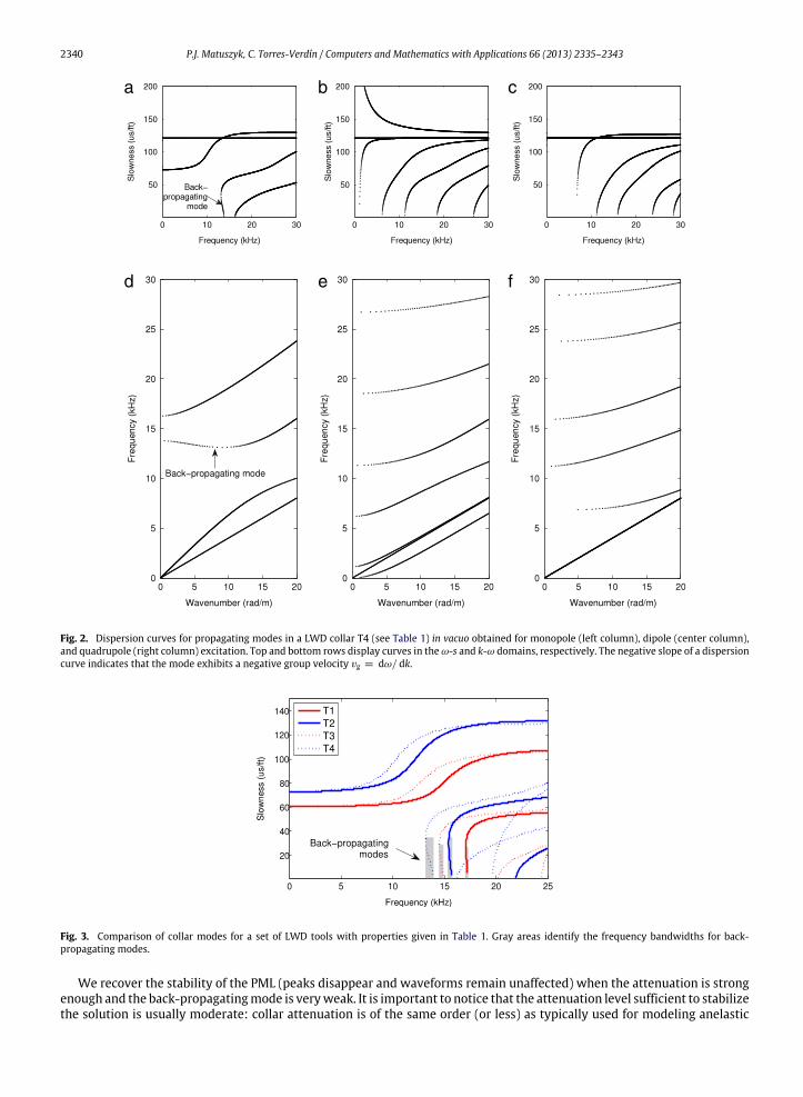
Fig. 3 shows dispersion curves related to the monopole collar modes for four different LWD instruments. Table 1summarizes the properties of the assumed LWD instruments. We consider two different collar diameters (6 3/4 and 81/2 inch) and two types of steel (with Poisson ratios ν = 0.3 and ν = 0.378). Gray areas in the plot indicate locations andbands of frequencies where collar back-propagating modes exist. The back-propagating collar mode has a cut-off frequencywhich increases as the diameter of the collar decreases, and the material becomes stiffer (ν decreases). Similarly, when toolproperties change in the samemanner, the bandwidth of the back-propagatingmode decreases. This behavior indicates thatthe difficulty of modeling collars made of softer material increases with collar thickness because the waveform spectrum isaffected at progressively lower frequencies and along a wider frequency band.
To investigate the influence of artificial damping in an LWD collar on formation modes, we calculated spectra (Fig. 4)and waveforms (Fig. 5) for open-borehole LWD logging measurements in a fast formation using two different collars: T1 inan 8 inch diameter borehole and T4 in a 10 inch diameter borehole. Table 2 describes the properties of the fast formationand borehole fluid. The tool has an array of 8 equally-spaced receivers (spacing equal to 15.24 cm) located 1.8288 m (1streceiver) apart from the acoustic transmitter (see Fig. 1). Results are calculated for monopole source excitationwith a Rickerwavelet of central frequency equal to 12 kHz.
As expected, in the absence of collar attenuation we face instability in the PML for both simulated collars, which ismanifested by large peaks in the waveform spectra and, consequently, by the presence of high-frequency non-physicalcomponent in the waveforms. The location of those peaks corresponds precisely with the predicted locations of collar back-propagating modes in the frequency domain. This deleterious phenomenon has stronger effects for the larger and softertools (T4), which confirms our previous observations. As the attenuation in the collar increases (in terms of quality factorsQP and QS , associated with compressional and shear velocities, respectively), the excited back-propagating modes exhibitsmaller amplitudes (smaller peaks in their spectra), but all formationmodes remain unaffected (P-, S-, and Stoneley arrivalsare in phase). We also observe a slight shift of the peaks related to the back-propagating mode toward higher frequencies,as the attenuation increases (Fig. 4(b)). This behavior is due to the assumed attenuation model given by Eq. (4). The largerthe attenuation (smaller Q ), the larger the real part of the velocity. In consequence, at a given frequency the correspondingwavelength increases and so does the cut-off frequency related to the mode.
2340 P.J. Matuszyk, C. Torres-Verdín / Computers and Mathematics with Applications 66 (2013) 2335–2343
a b c
d e f
Fig. 2. Dispersion curves for propagating modes in a LWD collar T4 (see Table 1) in vacuo obtained for monopole (left column), dipole (center column),and quadrupole (right column) excitation. Top and bottom rows display curves in theω-s and k-ω domains, respectively. The negative slope of a dispersioncurve indicates that the mode exhibits a negative group velocity vg = dω/ dk.
Fig. 3. Comparison of collar modes for a set of LWD tools with properties given in Table 1. Gray areas identify the frequency bandwidths for back-propagating modes.
We recover the stability of the PML (peaks disappear and waveforms remain unaffected) when the attenuation is strongenough and the back-propagatingmode is veryweak. It is important to notice that the attenuation level sufficient to stabilizethe solution is usually moderate: collar attenuation is of the same order (or less) as typically used for modeling anelastic

P.J. Matuszyk, C. Torres-Verdín / Computers and Mathematics with Applications 66 (2013) 2335–2343 2341
a b
Fig. 4. Relative spectra. Effect of anelastic attenuation (given in terms of quality factors Qp and Qs) on the damping of back-propagating collar modes whenlogging a fast formation with (a) T1 collar in an 8 inch diameter borehole, and (b) T4 collar in a 10 inch diameter borehole. Tool properties are summarizedin Table 1.
a b
c d
Fig. 5. Waveforms. Effect of anelastic attenuation (given in terms of quality factors Qp and Qs) on the damping of back-propagating collar modes whenlogging a fast formation: (a, b) full waveforms, and (c, d) zoomed waveforms at the 8th receiver obtained with collars: T1 in an 8 inch diameter borehole(left column) and T4 in a 10 inch diameter borehole (right column). Tool properties are given in Table 1; P and S markers identify the arrivals of formationcompressional and shear modes, respectively.
formations, but it is different for different tools. Here, a very weak attenuation (QP = 200 and QS = 100) for the T1 collaris sufficient to stabilize the solution in the PML, while for the T4 collar one has to enforce a stronger attenuation (QP = 50and QS = 25).
Fig. 6(a) and (c) shows the central frequencies and frequency bandwidths for the first back-propagating mode. Thesefigures provide insight to the location of back propagating modes in the frequency domain for solid steel collars within acommon range of geometrical dimensions, i.e.with internal radii between 1.5 and 3.5 cm, and external radii between 6 and12 cm, and for different elastic properties (compressional velocity equal to 5850 m/s and range of Poisson ratios from 0.27to 0.31). Fig. 6(b) and (d) shows analogous plots for the second back-propagating mode.
The analysis of those plots indicates that, unavoidably, at least one back-propagating mode exists when logging-while-drilling with a monopole acoustic source. Therefore, special attention must be paid to avoid spurious back-propagatingmodes when modeling monopole LWD sonic measurements and using the PML technique as an absorbing layer. Thetypical central frequency of the monopole acoustic source falls within 8–15 kHz (in order to excite a measurable formationcompressional wave), whereby the frequency bandwidth that needs to be taken into account for simulations has to spanat least the 25–45 kHz bandwidth, respectively, even when assuming a source with a narrow spectrum (such as the Rickerwavelet used in the simulation examples documented in this paper). Presence of undesirable mode(s) is more prominent

2342 P.J. Matuszyk, C. Torres-Verdín / Computers and Mathematics with Applications 66 (2013) 2335–2343
a
c
b
d
Fig. 6. Location of the 1st and 2nd back-propagating monopole modes calculated for a steel LWD collar: (a) location and (c) bandwidth of the 1st back-propagatingmode, (b) location and (d) bandwidth of the 2nd back-propagatingmode. Lines in the same color identify results obtained for increasing valuesof Poisson’s ratio, ν, from 0.27 to 0.31 with step equal to 0.01. The center frequency decreases as Poisson’s ratio increases; the opposite trend takes placefor the case of frequency bandwidth; Rin and Rout denote the inner and outer collar radius, respectively.
for thicker collars, as the center frequency moves toward lower frequencies (precisely where the monopole excited energyconcentrates) and its bandwidth increases. Stiffness of the collar material has a secondary effect: it slightly modifies thecenter frequency, but has a larger effect on frequency bandwidth for thicker collars.
4. Conclusions
We analyzed the presence of back-propagating modes in an elastic hollow cylindrical waveguide and their effects on thestability of the PML technique. It was shown that, for the class of coupled wave propagation problems related to monopoleLWD sonic logging, the presence of a massive steel mandrel causes unavoidable excitation of a back-propagating collarmode within the frequency band of interest. The location of this undesirable mode can be predicted by assuming a simplegeometrical collar model and using an analytical method. This information can be used for omitting numerical simulationsfor discrete frequencies falling into the frequency rangewhere a back-propagatingmode existswhenever the use of anelasticattenuation is undesirable, e.g. when designing a collar acoustic insulator. A priori knowledge about the frequency locationof back-propagating mode is helpful to choose the suitable values of quality factors (obtained via numerical simulation fora particular discrete frequency) needed to attenuate the undesirable mode.
The presence of collar back-propagating mode causes instability in the PML absorbing layer precisely within thefrequency range where this mode exists. We proposed the introduction of artificial attenuation for the collar to circumventthis problem. Such a strategy results in the damping of all collar modes without affecting formation modes. Because of therelatively small amplitude of the back-propagating mode, usually a moderate attenuation causes its amplitude to becomenegligible in the PML layer, thereby securing stability of the solution.
P.J. Matuszyk, C. Torres-Verdín / Computers and Mathematics with Applications 66 (2013) 2335–2343 2343
Acknowledgments
The work reported in this paper was funded by The University of Texas at Austin’s Research Consortium on FormationEvaluation, jointly sponsored by Afren, Anadarko, Apache, Aramco, Baker-Hughes, BG, BHP Billiton, BP, Chevron, ChinaOilfield Services, LTD., ConocoPhillips, ENI, ExxonMobil, Halliburton, Hess, Maersk, Marathon Oil Corporation, MexicanInstitute for Petroleum, Nexen, ONGC, OXY, Petrobras, PTT Exploration and Production, Repsol, RWE, Schlumberger, Shell,Statoil, TOTAL, Weatherford, Wintershall and Woodside Petroleum Limited.
We are indebted to the Texas Advanced Computing Center (TACC) at the University of Texas at Austin for providing thehigh-performance computing resources that were used for the completion of this research project.
References
[1] J. Bérenger, A perfectly matched layer for the absorption of electromagnetic waves, Journal of Computational Physics 114 (2) (1994) 185–200.[2] W.C. Chew, W.H. Weedon, A 3D perfectly matched medium from modified maxwells equations with stretched coordinates, Microwave and Optical
Technology Letters 7 (13) (1994) 599–604.[3] W.C. Chew, J.M. Jin, E. Michielssen, Complex coordinate system as a generalized absorbing boundary condition, in: IEEE Antennas and Propagation
Society International Symposium 1997, Vols. 1–4.[4] F. Collino, P. Monk, The perfectly matched layer in curvilinear coordinates, SIAM Journal On Scientific Computing 19 (6) (1998) 2061–2090.[5] P.J.Matuszyk, L. Demkowicz, Parametric finite elements, exact sequences andperfectlymatched layers, ComputationalMechanics 51 (1) (2013) 35–45.
http://dx.doi.org/10.1007/s00466-012-0702-1.[6] I. Tolstoy, E. Usdin, Wave propagation in elastic plates—low and high mode dispersion, Journal of The Acoustical Society of America 29 (1) (1957)
37–42. http://dx.doi.org/10.1121/1.1908675.[7] T.R. Meeker, A.H. Meitzler, Physical Acoustics, Vol. 1, Academic Press, New York, 1961. Guided wave propagation in elongated cylinders and plates
(Chapter).[8] D.C. Gazis, Three-dimensional investigation of the propagation of waves in hollow circular cylinder, 1. Analytical foundation, Journal of the Acoustical
Society of America 31 (5) (1959) 568–573. http://dx.doi.org/10.1121/1.1907753.[9] D.C. Gazis, Three-dimensional investigation of the propagation of waves in hollow circular cylinder, 2. Numerical results, Journal of the Acoustical
Society of America 31 (5) (1959) 573–578. http://dx.doi.org/10.1121/1.1907754.[10] E. Bécache, S. Fauqueux, P. Joly, Stability of perfectly matched layers, group velocities and anisotropic waves, Journal of Computational Physics 188
(2) (2003) 399–433. http://dx.doi.org/10.1016/S0021-9991(03)00184-0.[11] P.-R. Loh, A.F. Oskooi, M. Ibanescu, M. Skorobogatiy, S.G. Johnson, Fundamental relation between phase and group velocity, and application to the
failure of perfectly matched layers in backward-wave structures, Physical Review E 79 (6) (2009) http://dx.doi.org/10.1103/PhysRevE.79.065601.[12] E.A. Skelton, S.D.M. Adams, R.V. Craster, Guided elastic waves and perfectly matched layers, Wave Motion 44 (7–8) (2007) 573–592.
http://dx.doi.org/10.1016/j.wavemoti.2007.03.001.[13] K.C.Meza-Fajardo, A.S. Papageorgiou, A nonconvolutional, split-field, perfectlymatched layer forwave propagation in isotropic and anisotropic elastic
media: stability analysis, Bulletin of the Seismological Society of America 98 (4) (2008) 1811–1836. http://dx.doi.org/10.1785/0120070223.[14] P.J. Matuszyk, L. Demkowicz, C. Torres-Verdín, Solution of coupled acoustic-elastic wave propagation problems with anelastic attenuation using
automatic hp-adaptivity, Computer Methods in Applied Mechanics and Engineering 213–216 (2012) 299–313.http://dx.doi.org/10.1016/j.cma.2011.12.004.
[15] P.J. Matuszyk, C. Torres-Verdín, D. Pardo, Frequency-domain finite-element simulations of 2D sonic wireline borehole measurements acquired infractured and thinly bedded formations, Geophysics 78 (4) (2013) D193–D207. http://dx.doi.org/10.1190/geo2012-0397.1.
[16] C. Michler, L. Demkowicz, C. Torres-Verdin, Numerical simulation of borehole acoustic logging in the frequency and time domains with hp-adaptivefinite elements, Computer Methods in Applied Mechanics and Engineering 198 (2009) 1821–1838.
[17] L. Demkowicz, Computing with hp-Adaptive Finite Elements, in: One and Two Dimensional Elliptic and Maxwell Problems of Chapman & Hall/CRCApplied Mathematics and Nonlinear Science Series, vol. 1, Chapman & Hall/CRC Press, 2006.
[18] L. Demkowicz, J. Kurtz, D. Pardo, M. Paszyński, W. Rachowicz, A. Zdunek, Computing with hp-Adaptive Finite Elements, in: Frontiers: ThreeDimensional Elliptic and Maxwell Problems with Applications of Chapman & Hall/CRC Applied Mathematics and Nonlinear Science Series, vol. 2,Chapman & Hall/CRC Press, 2008.
[19] T.J. Chung, Applied ContinuumMechanics, Cambridge University Press, 1996.[20] K. Aki, P.G. Richards, Quantitative Seismology, University Science Books, 2002.[21] A. Adamou, R. Craster, Spectral methods for modelling guided waves in elastic media, Journal of the Acoustical Society of America 116 (3) (2004)
1524–1535. http://dx.doi.org/10.1121/1.1777871.[22] F. Karpfinger, B. Gurevich, A. Bakulin, Modeling of wave dispersion along cylindrical structures using the spectral method, Journal of the Acoustical
Society of America 124 (2) (2008) 859–865. http://dx.doi.org/10.1121/1.2940577.