Embed Size (px)
Citation preview

Computer Vision and Image Understanding 115 (2011) 1011–1022
Contents lists available at ScienceDirect
Computer Vision and Image Understanding
journal homepage: www.elsevier .com/ locate/cviu
Invariant representative cocycles of cohomology generators using irregulargraph pyramids
Rocio Gonzalez-Diaz a,⇑, Adrian Ion b,d, Mabel Iglesias-Ham b,c, Walter G. Kropatsch b
a Applied Math Department, School of Computer Engineering, University of Seville, Reina Mercedes Avenue, CP: 41012 Seville, Spainb Pattern Recognition and Image Processing Group, Vienna University of Technology, Faculty of Informatics, Institute of Computer Aided Automation,Favoritenstr. 9/1832, A-1040 Vienna, Austriac Pattern Recognition Department, Advanced Technologies Application Center, 7th Avenue #21812 %218 and 222, Siboney Neighborhood, Playa, C.P. 12200, Havana City, Cubad Institute for Numerical Simulation, Faculty of Mathematics and Natural Sciences, University of Bonn, Wegelerstr. 6, 53115 Bonn, Germany
a r t i c l e i n f o
Article history:Available online 16 March 2011
Keywords:Graph pyramidsRepresentative cocycles of cohomologygenerators
1077-3142/$ - see front matter � 2011 Elsevier Inc. Adoi:10.1016/j.cviu.2010.12.009
⇑ Corresponding author.E-mail addresses: [email protected] (R. Gonzalez-Dia
Ion), [email protected], miglesias@[email protected] (W.G. Kropatsch).
a b s t r a c t
Structural pattern recognition describes and classifies data based on the relationships of features andparts. Topological invariants, like the Euler number, characterize the structure of objects of any dimen-sion. Cohomology can provide more refined algebraic invariants to a topological space than does homol-ogy. It assigns ‘quantities’ to the chains used in homology to characterize holes of any dimension. Graphpyramids can be used to describe subdivisions of the same object at multiple levels of detail. This paperpresents cohomology in the context of structural pattern recognition and introduces an algorithm to effi-ciently compute representative cocycles (the basic elements of cohomology) in 2D using a graph pyramid.An extension to obtain scanning and rotation invariant cocycles is given.
� 2011 Elsevier Inc. All rights reserved.
1. Introduction
Image analysis deals with digital images as input to pattern rec-ognition systems with the purpose to extract information abouttheir content, usually objects. Objects appear in images affectedby transformations (e.g. rotation, zoom, projection) and noise.Topological features have the ability to ignore changes in thegeometry of objects by extracting object properties invariant toelastic transformations. Simple topological features are for exam-ple the number of connected components, the number of holes,etc., while more refined ones, like homology and cohomology,characterize holes and their relations.
An example application of topological features is topology sim-plification, an active field in geometric modeling and medicalimaging where high-resolution surfaces are created through iso-surface extraction from volumetric representations, obtained by3D photography, CT, or MRI. Iso-surfaces often contain many topo-logical errors in the form of tiny handles. These nearly invisibleartifacts hinder subsequent operations like mesh simplification,re-meshing, and parametrization. See, for example [1]. Anotherapplication is shape description and matching, where persistenceand homology of a function defined on a shape have been success-fully applied to extract shape features [2].
ll rights reserved.
z), [email protected] (A..co.cu (M. Iglesias-Ham),
A 2D image is the result of projecting a 3D scene into the imageplane. Often the precise camera parameters are not known and stillhumans have no problem in correctly interpreting the displayedobjects in the image. A 3D object is surrounded by a reflecting sur-face which itself may split into several smaller but connectedpatches which can be characterized by their color, their textureor other visual properties. The visible part of the object’s surfacemaps into a region of the image which shows the same adjacenciesof patches as the original surface (because the camera sees the sameside of the surface) although the geometry of the patches maychange due to projection, due to camera or object movement ordue to deformations of the object. Sometimes a collection ofpatches is completely surrounded by some other surface patches,e.g. a fancy soccer ball on a Spanish T-shirt (see Fig. 1). Althoughboth the picture of the ball as well as the T-shirt may have a spe-cific patch structure (stripes on shoulder and arms, logo) it is clearwhich subset of regions forms the ball and which regions belong tothe remaining T-shirt. A simplified version could describe the pix-els of the T-shirt 1’s and the ball’s pixels by 0 (see Fig. 1). Then theball is a hole in the T-shirt as long as the surrounding of the ball isvisible and not occluded by other objects. It may be highly difficultto uniquely and reliably identify any of the involved small patchesindividually under difficult geometric deformations while theoverall arrangement of patches forming the ball is mostly invariantto these geometric deformations. How to segment patches intomeaningful aggregations has been dealt with in many other seg-mentation methods and it is not the main emphasis of this paper.We therefore restrict ourselves in the following on binary images

Fig. 1. (a) Original image: ball on T-shirt of world champions 2010 in soccer; (b) asegmentation of the original image using pyramids.
1012 R. Gonzalez-Diaz et al. / Computer Vision and Image Understanding 115 (2011) 1011–1022
with the understanding that each region may be the collection ofseveral subregions belonging together.
Considering 2D binary images, an object is defined by a con-nected set (4-connectivity) of foreground pixels. A region adjacencygraph (RAG) encodes the adjacency of regions in a partition. Theholes in a RAG associated to an object of a 2D binary digital imagecan be characterized by establishing an equivalence between allthe cycles as follows: two cycles are equivalent if one can be ob-tained from the other by joining to it one or more degenerate cycles(cycles with exactly four edges). For example, there is only oneequivalence class for the foreground (gray pixels) of the digital im-age in Fig. 2, which represents the unique white hole. This is sim-ilar to considering the digital image as a cell complex1 [3] (seeFig. 2c). Unfortunately digital images are not ‘clean’, noise can createmany unwanted holes which complicate the correct interpretation.One can ask for the edges we have to delete in order to ‘destroy’ ahole. In the example in Fig. 2, it is not enough to delete only oneedge. The deletion of the bold edges in Fig. 2c together with the facesthat they bound produces the ‘disappearing’ of the hole. The set ofbold edges in Fig. 2c define a 1-cocycle, a topological invariant ofthe respective object. Equivalence classes of such cocycles are theelements of cohomology.
To cope with complexity issues that arise when highly complexalgorithms must be applied to huge amounts of data, graph pyra-mids are used. These hierarchical data structures offer possibilitiesto reduce the amount of data by local operations which can be ap-plied in parallel and which have the enormous advantage to pre-serve the topological properties of the data. Hence the search forindependent cocycles can be correctly done on a fraction of thedata at the top of the pyramid. The simplified geometry of thesecocycles can then be delineated top-down through the levels ofthe pyramid by again local processes up to the high accuracy ofthe base level.
Maybe due to its more abstract nature, lacking a geometricmeaning and due to its computation complexity, cohomology hasnot been yet widely applied to pattern recognition and image pro-cessing. This paper is possibly the first attempt to use it in the con-text of digital images. For this purpose, in this paper we considerthe best known environment which are 2D images whereas nD isthe ultimate goal. Concepts related to cohomology can have asso-ciated interpretations in graph theory. Having these interpreta-tions opens the door for applying classical efficient graph theoryalgorithms to compute and manipulate these features. Besides,for objects embedded in R3, homology – a wider used topologicalinvariant, and cohomology groups are isomorphic. But the ringstructure presented in cohomology characterizes the relations be-tween 2-holes (cohomology generators of dimension 1), whichhomology does not. Indeed, dealing with homology and cohomol-ogy properties, representative cycles and cocycles, and their com-
1 Intuitively a cell complex is defined by a set of 0-cells (vertices) that bound a setof 1-cells (edges), that bound a set of 2-cells (faces), etc.
putation is quite different and doing this study in 2D givesimportant insights which should be relevant for extension to nD,n > 2. Initial results regarding this work have been presented in[4]. The current paper extends our earlier publication with detailedinsights and proofs, and a refinement of the previous method thatmakes the obtained cocycles scanning and rotation invariant in thecase of an identical discretization.
The paper is organized as follows: Sections 2 and 3 recall graphpyramids and cohomology, and make initial connections. In Section4, preserving-topology properties in irregular graph pyramids aregiven. Section 5 presents the proposed method. Section 6 uses theproperties of the proposed method to extend it and obtain scanningand rotation invariant cocycles. Section 7 concludes the paper.
2. Irregular graph pyramids
A graph (see for example [5]) is an ordered pair G = (V,E) com-prising a set V of vertices and a set E of edges. Each edge e 2 E isincident to two not necessarily distinct vertices v,w 2 V, writtenas e = (v,w). An edge e = (v,w) is said to be directed if the pair(v,w) is an ordered pair. An edge is said to be a self-loop if v = w.The edge e = (v,w) is called a parallel edge iff $e0 2 E, e0 – e s.t.e0 = (v,w). A graph is called undirected if none if its edges is direc-ted, and it is called planar if it can be drawn in a plane with noedges crossing (vertices are drawn as points and edges as lines con-necting their incident vertices). Given a graph G = (V,E) removingan edge e 2 E will result in the graph G0 = (V,E n{e}), contractingthe edge e = (v,w) implies removing it and identifying its incidentvertices s.t any remaining edge previously incident to v or w isnow incident to the unique vertex v = w.
Given a decomposition of an object or image into regions a re-gion adjacency graph (RAG) is an undirected graph that encodesthe adjacency of regions in a partition. A vertex is associated toeach region, vertices of neighboring regions are connected by anundirected edge. Classical RAGs do not contain any self-loops orparallel edges. An extended region adjacency graph (eRAG) is aRAG that contains the so-called pseudo edges, which are self-loopsand parallel edges used to encode neighborhood relations to a cellcompletely enclosed by one or more other cells [6]. The dual graphof an eRAG G is called a boundary graph (BG) and is denoted by G (Gis said to be the primal graph of G). The edges of G represent theboundaries (borders) of the regions encoded by G, and the verticesof G represent points where boundary segments meet. G and G areplanar graphs. There is a one-to-one correspondence between theedges of G and the edges of G, which induces a one-to-one corre-spondence between the vertices of G and the 2D cells (will be de-noted by faces2) of G. The dual of G is again G. The followingoperations are equivalent: edge contraction in G with edge removalin G, and edge removal in G with edge contraction in G.
A (dual) irregular graph pyramid [7,8,6,9] is a stack of successivelyreduced planar graphs P ¼ fðG0;G0Þ; . . . ; ðGn;GnÞg. Each level ðGk;GkÞ,0 < k 6 n, is obtained by first contracting edges in Gk�1 (removal inGk�1), if their end vertices have the same label (regions should bemerged), and then removing edges in Gk�1 (contraction in Gk�1)to simplify the structure. The contracted and removed edges aresaid to be contracted or removed (sometimes called removal edges)in ðGk�1;Gk�1Þ. In each Gk�1 and Gk�1, contracted edges form treescalled contraction kernels. One vertex of each contraction kernel iscalled a surviving vertex and is considered to have ‘survived’ toðGk;GkÞ. The vertices of a contraction kernel in level k � 1 formthe reduction window of the respective surviving vertex v in levelk. The receptive field of v is the (connected) set of vertices from level0 that have been ‘merged’ to v over levels 0, . . . ,k. The equivalent
2 Not to be confused with the vertices of the dual of a RAG (sometimes also denotedby the term faces).
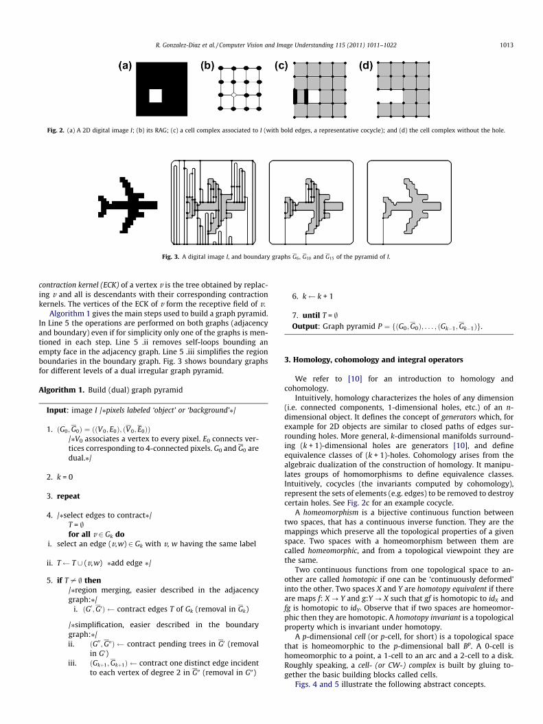
Fig. 3. A digital image I, and boundary graphs G6, G10 and G15 of the pyramid of I.
Fig. 2. (a) A 2D digital image I; (b) its RAG; (c) a cell complex associated to I (with bold edges, a representative cocycle); and (d) the cell complex without the hole.
R. Gonzalez-Diaz et al. / Computer Vision and Image Understanding 115 (2011) 1011–1022 1013
contraction kernel (ECK) of a vertex v is the tree obtained by replac-ing v and all is descendants with their corresponding contractionkernels. The vertices of the ECK of v form the receptive field of v.
Algorithm 1 gives the main steps used to build a graph pyramid.In Line 5 the operations are performed on both graphs (adjacencyand boundary) even if for simplicity only one of the graphs is men-tioned in each step. Line 5 .ii removes self-loops bounding anempty face in the adjacency graph. Line 5 .iii simplifies the regionboundaries in the boundary graph. Fig. 3 shows boundary graphsfor different levels of a dual irregular graph pyramid.
Algorithm 1. Build (dual) graph pyramid
Input: image I /⁄pixels labeled ‘object’ or ‘background’⁄/
1. ðG0;G0Þ ¼ ððV0; E0Þ; ðV0; E0ÞÞ
/⁄V0 associates a vertex to every pixel. E0 connects ver-tices corresponding to 4-connected pixels. G0 and G0 aredual.⁄/2. k = 0
3. repeat
4. /⁄select edges to contract⁄/
T = ;for all v 2 Gk doi. select an edge (v,w) 2 Gk with v, w having the same label
ii. T T [ (v,w) ⁄add edge ⁄/
5. if T – ; then
/⁄region merging, easier described in the adjacencygraph:⁄/i. ðG0;G0Þ contract edges T of Gk (removal in Gk)
/⁄simplification, easier described in the boundarygraph:⁄/ii. ðG00;G00Þ contract pending trees in G0 (removal
in G0)iii. ðGkþ1;Gkþ1Þ contract one distinct edge incident
to each vertex of degree 2 in G00 (removal in G00)
6. k k + 1
7. until T = ;Output: Graph pyramid P ¼ fðG0;G0Þ; . . . ; ðGk�1;Gk�1Þg.
3. Homology, cohomology and integral operators
We refer to [10] for an introduction to homology andcohomology.
Intuitively, homology characterizes the holes of any dimension(i.e. connected components, 1-dimensional holes, etc.) of an n-dimensional object. It defines the concept of generators which, forexample for 2D objects are similar to closed paths of edges sur-rounding holes. More general, k-dimensional manifolds surround-ing (k + 1)-dimensional holes are generators [10], and defineequivalence classes of (k + 1)-holes. Cohomology arises from thealgebraic dualization of the construction of homology. It manipu-lates groups of homomorphisms to define equivalence classes.Intuitively, cocycles (the invariants computed by cohomology),represent the sets of elements (e.g. edges) to be removed to destroycertain holes. See Fig. 2c for an example cocycle.
A homeomorphism is a bijective continuous function betweentwo spaces, that has a continuous inverse function. They are themappings which preserve all the topological properties of a givenspace. Two spaces with a homeomorphism between them arecalled homeomorphic, and from a topological viewpoint they arethe same.
Two continuous functions from one topological space to an-other are called homotopic if one can be ‘continuously deformed’into the other. Two spaces X and Y are homotopy equivalent if thereare maps f: X ? Y and g:Y ? X such that gf is homotopic to idX andfg is homotopic to idY. Observe that if two spaces are homeomor-phic then they are homotopic. A homotopy invariant is a topologicalproperty which is invariant under homotopy.
A p-dimensional cell (or p-cell, for short) is a topological spacethat is homeomorphic to the p-dimensional ball Bp. A 0-cell ishomeomorphic to a point, a 1-cell to an arc and a 2-cell to a disk.Roughly speaking, a cell- (or CW-) complex is built by gluing to-gether the basic building blocks called cells.
Figs. 4 and 5 illustrate the following abstract concepts.

Fig. 4. Example of cell, chain, boundary and cycle.
Fig. 5. Example of cochain, cocycle and coboundary.
1014 R. Gonzalez-Diaz et al. / Computer Vision and Image Understanding 115 (2011) 1011–1022
3.1. Homology
The notion of p-chain is defined as a formal sum of p-cells. Thechains are considered over Z=2 coefficients i.e. a p-cell is eitherpresent in a p-chain (coefficient 1) or absent (coefficient 0) – anycell that appears twice vanishes. The set of p-chains form an abe-lian group called the p-chain group Cp. This group is generatedby all the p-cells. The boundary operator is a set of homomorphisms{@p: Cp ? Cp�1}pP0 connecting two consecutive dimensions. By lin-earity, the boundary of any p-chain is defined as the formal sum ofthe boundaries of each p-cell that appears in the chain. The bound-ary of 0-cells (i.e. points) is always 0. A chain complex is the set ofall the chain groups connected by the boundary operator:� � � !
@pþ1Cp!
@pCp�1 ! � � �!
@1 C0!@0 0.
A p-chain r is called a p-cycle if @p (r) = 0. If r = @p+1(l) for some(p + 1)-chain l then r is called a p-boundary. Two p-cycles a and a0
are homologous if there exists a p-boundary b such that a = a0 + b.Denote the groups of p-cycles and p-boundaries by Zp and Bp
respectively. For each p, @p�1@p = 0. In other words, all p-boundariesare p-cycles (Bp # Zp). Define the pth homology group to be thequotient group Hp = Zp/Bp, for all p.
Each element of Hp is a class obtained by adding each p-bound-ary to a given p-cycle a. Then a is a representative p-cycle of thehomology class a + Bp.
Since the chains are considered over Z=2 coefficients, the chaingroups are vector spaces and the boundary operators are linearoperators. The cycle and boundary groups are just the kernel andimage of such operator. The homology group is a quotient space.
3.2. Cohomology
Cohomology groups are constructed by turning chain groups intogroups of homomorphisms and boundary operators into their dualhomomorphisms. Define a p-cochain as a homomorphismc : Cp ! Z=2. We can see a p-cochain as a binary mask of the setof p-cells: imagine you order all p-cells in the complex. (let’s saywe have n p-cells, and call this ordered set Sp). Then a p-cochainc is a binary mask of n values in {0,1}n, where n is the number ofp-cells in the complex. When no confusion can arise, we will iden-tify the p-cochain c with the set S of p-cells that are evaluated to 1by c.
The p-cochains form the set Cp which is a group. The boundaryoperator defines a dual set of homomorphisms, the coboundaryoperator {dp: Cp ? Cp+1}pP0, such that dp(c) = c@p+1 for any p-cochain
c. Since the coboundary operator runs in a direction opposite to theboundary operator, it raises the dimension. Its kernel is the groupof cocycles and its image is the group of coboundaries. A p-cochain cis a p-cocycle if dpcð¼ c@pþ1Þ : Cpþ1 ! Z=2 is the null homomor-phism. A p-cochain d is a p-coboundary if there exists a (p � 1)-co-chain e such that d = dp�1e(=e@p). Two p-cocycles c and c0 arecohomologous if there exists a p-coboundary d such that c = c0 + d.The pth cohomology group is defined as the quotient of p-cocyclemodulo p-coboundary groups, Hp = Zp/Bp, for all p. Each elementof Hp is a class obtained by adding each p-coboundary to a givenp-cocycle c. Then c is a representative p-cocycle of the cohomologyclass c + Bp, denoted by [c].
Definition 3.1. A set of p-cocycles {c1, . . . ,cn} is a basis of repre-sentative p-cocycles if:
� Any other p-cocycle c can be written as a linear combination ofthe p-cocycles of the set plus a p-coboundary, that is:
c ¼Xn
i¼1
kici þ dp�1e
where ki = 0, 1 and e is a (p � 1)-cochain.� None of the p-cocycles in the set can be written as a linear com-
bination of the rest plus a p-coboundary (minimality).
Remark 3.1. If {c1, . . . ,cn} is a basis of representative p-cocyclesthen {[c1], . . . , [cn]} is a basis of the pth cohomology group of theobject. Each [ci] is a cohomology generator.
3.3. Integral operator
Starting from a chain complex, � � �!@2 C1!@1 C0!
@0 0, take a q-cell rand a (q + 1)-chain a. An integral operator [11] is defined as the setof homomorphisms {/p: Cp ? Cp+1}pP0 such that /q(r) = a,/q(l) = 0 if l is a q-cell different to r, and for all p – q and anyp-cell c we have /p(c) = 0. It is extended to all p-chains by linearity.
An integral operator {/p: Cp ? Cp+1}pP0 satisfies the chain-homotopy property iff /p@p+1/p = /p for each p. For /p satisfyingthe chain-homotopy property, define pp = idp + /p�1@p + @p+1/p
where {idp: Cp ? Cp}pP0 is the identity. Defineimpp = {b 2 Cpj$a 2 Cps.t.pp(a) = b}. Then, � � �!@2 imp1!
@1 imp0!@0 0 is
a chain complex and {pp: Cp ? impp}pP0 is a chain equivalence

Fig. 6. The cell complex K, K0 and K00; and the homomorphisms /rp;pr
p; irp and /s
p;psp; is
p .
R. Gonzalez-Diaz et al. / Computer Vision and Image Understanding 115 (2011) 1011–1022 1015
[10]. Its chain-homotopy inverse is the inclusion map {ip: im-pp ? Cp}pP0. Integral operators satisfying the chain-homotopyproperty can be seen as a kind of inverse boundary operator: theyraise the dimension and satisfy the nilpotent condition /p+1/p = 0for all p. Although, in general, /p�1@p – idp and @p+1/p – idp, whathappens is /p@p+1/p = /p for all p (which would be equivalent tox � 1
x � x ¼ x for x 2 R n f0g). Consider, for example, the cell complexK in Fig. 6 on the left. The integral operator associated to the re-moval of the edge e is given by /r
1ðeÞ ¼ A. Then, pr1ðeÞ ¼ ðid1þ
/r0@1 þ @2/
r1ÞðeÞ ¼ eþ aþ f þ dþ e ¼ aþ f þ d, pr
2ðAÞ ¼ 0;pr2ðBÞ ¼
A (A + B is renamed as A in K0) and prp is the identity over the other
p-cells of K, p = 0, 1, 2. The removal of edge e decreases the degreeof vertex v allowing for further simplification.
The following lemma guarantees the correctness of the downprojection procedure for computing cocycles given in Section 5.Since graph pyramids offer possibilities to reduce the amount ofdata by local operations, then the search for independent cocyclescan be done on the top of the pyramid. Hence, the following lemmaguarantees that these cocycles can be correctly delineated top-down through the levels of the pyramid.
Lemma 3.2. Let {/p: Cp ? Cp+1}pP0 be an integral operator satisfyingthe chain-homotopy property. The chain complexes� � �!@2 ! C1!
@1 C0!@0 0 and � � �!@2 imp1!
@1 imp0!@0 0 have isomorphic
homology and cohomology groups. If c : impp ! Z=2 is a represen-tative p-cocycle of a cohomology generator, then cp : Cp ! Z=2 is arepresentative p-cocycle of the same generator.
Fig. 7. The homomorphisms /rp ;pr
p and /sp;ps
p .
Proof. An integral operator that satisfies the chain homotopyproperty, is a chain homotopy of the identity {idp: Cp ? Cp}pP0 to{ippp: Cp ? Cp}pP0. Therefore, {pp: Cp ? impp}pP0 is a chain equiv-alence and chain equivalences induce isomorphisms on homologyand cohomology (see [10]). h
For example, consider the cell complex K0 of Fig. 6. The 1-co-chain a⁄, defined by the set {b, f} of edges of K0, is a 1-cocycle which‘blocks’ the white hole H (in the sense that all the cycles represent-ing the hole must contain an odd number of edges of a⁄). Thenb ¼ a�pr
1 is defined by the set {b, f,e} of edges of K. a and b are both1-cocycles representing the same white hole H.
4. Preserving topology in irregular graph pyramids
Considering binary images, an object is defined by a connectedset (4-connectivity) of foreground pixels. A partition of the wholespace (foreground and background) in cells is called a cell subdivi-sion. The referred partition could be obtained from any of the pla-nar graphs in every level of the pyramid.
Fix a level ðGi;GiÞ, the cell complex associated to the foregroundobject, called boundary cell complex, denoted by Ki, is obtained fromðGi;GiÞ by taking all faces of Gi corresponding to vertices of Gi,whose receptive fields contain (only) foreground pixels, and addingall edges and vertices needed to represent the faces. The p-chaingroup generated by the p-cells of Ki is denoted by Cp(Ki).
The following lemma guarantees that the local operations ap-plied to build a graph pyramid preserve the topological propertiesof the initial data.
Lemma 4.1. The boundary cell complex is well-defined. All theboundary cell complexes of a given irregular dual graph pyramid arecell subdivisions of the same object. Therefore, all these cell complexesare homeomorphic.
Proof. Our input is a binarized 2D digital image. An object is the 4-connected set of foreground pixels. Since we only remove an edgein Gk when it is in the boundary of two different regions that havethe same label (region merging), and contract an edge in Gk when itis incident to a vertex of degree 2 or it is a pendant edge (simplifi-cation), all the new p-cells created are homeomorphic to p-dimen-sional balls, p = 0, 1, 2. h
As a result of Lemma 4.1, topological invariants computed ondifferent levels of the pyramid are equivalent.
For the purpose of this paper, a new cell complex called homol-ogy-generator level, is added over the boundary cell complex ob-tained from the top (last) level of the pyramid (see Fig. 8). Thisnew cell complex is denoted by KH and it is a set of regions sur-rounded by a set of self-loops incident to a single vertex. To obtainthis cell complex, on the top of the computed pyramid, we com-pute a spanning tree of the boundary graph of the top level ofthe pyramid, and contract all the edges that belong to it. Note thatKH is no longer homeomorphic to any Ki, but homotopic.
Lemma 4.2. The two operations used to construct an irregular graphpyramid: edge removal and edge contraction, are integral operatorssatisfying the chain-homotopy property.
Proof. Fix a level ðGi;GiÞ, suppose an edge e in Gi is removed. SinceGi is planar, then e is in the boundary of two 2-cells (or regions) Aand B (see Fig. 6). The integral operator /r associated to this edgeremoval is given by /r
1ðeÞ ¼ B (see Fig. 7). Now, suppose that anedge d of Gi, with a vertex v of degree 2 in its boundary, is con-tracted (see Fig. 6). The integral operator /s associated to this edgecontraction is given by /s
0ðvÞ ¼ d (see Fig. 7). h
Starting from a cell decomposition of an object, its homologystudies incidence relations of its subdivision. Cohomology arisesfrom the algebraic dualization of the construction of homology.Both homology and cohomology are homotopy invariants.
Corollary 4.3. The boundary cell complex of any level of the pyramidand the homology-generator level have isomorphic homology andcohomology groups.
As a consequence of Lemmas 3.2 and 4.2 we have:
Lemma 4.4. Fix a level ðGi;GiÞ, suppose an edge e in Gi, which is in theboundary of a region B, is removed. Let /r
1ðeÞ ¼ B be the integral

1016 R. Gonzalez-Diaz et al. / Computer Vision and Image Understanding 115 (2011) 1011–1022
operator associated to this removal. Let a⁄ be a 1-cocycle defined by aset of edges S in Gi n feg. If an odd number of edges of a⁄ is in B, thenS [ {e} defines a 1-cocycle in Ki; otherwise, it is S which defines a 1-cocycle in Ki.
In terms of embedded graphs, an integral operator maps a ver-tex/point to exactly one of its incident edges and an edge to ex-actly one of its incident faces. In every level of a graphpyramid, the contraction kernels make up a spanning forest. Aforest composed of k connected components, spanning agraph with n vertices, has k root vertices, n � k other vertices,and also n � k edges. These edges can be oriented toward therespective root such that each edge has a unique starting vertex.Then, integral operators mapping the starting vertices to thecorresponding edge of the spanning forest can be defined asfollows: /0(vi) = ej, where ej is the edge incident to vi, orientedaway from it.
The following lemma guarantees that all integral operators thatcreate homeomorphisms are in fact a combination of the two oper-ations used to construct irregular graph pyramids.
Lemma 4.5. All integral operators that create homeomorphisms canbe represented in a dual graph pyramid. This is equivalent to: given aninput image ðG0;G0Þ and its associated cell complex Z = {C0,C1,C2}, acell complex Z0 ¼ fC00;C
01;C
02g with Z, Z0 homeomorphic, and Z a
refinement of Z0 i.e. C00 # C0; C01 # C1; and C02 # C2, then there exists apyramid P s.t. Z0 is the cell complex associated to some levelðGk;GkÞ; k P 0; of P.
5. Representative cocycles in irregular graph pyramids
A method for efficiently computing representative cycles ofhomology generators using an irregular graph pyramid is givenin [12]. In [13] a novel algorithm for correctly visualizing graphpyramids, including multiple edges and self-loops is given. Thisalgorithm preserves the geometry and the topology of the originalimage and has been used to produce the images throughout the pa-per (see Fig. 9).
In this paper, representative cocycles are computed and drawnin the boundary graph of any level of a given irregular graph pyr-amid. They are computed in the top level and down projectedusing the described process.
In the homology-generator level (see Fig. 8c), each self-loop athat surrounds a region of the background (hole of a region R ofthe foreground) is a representative 1-cycle of a homologygenerator.
Let KH be the homology-generator level. Without loss of gener-ality, we can suppose that KH is connected. If not, repeat the follow-ing reasoning for each connected component (region) of KH. Let{a1, . . . ,an} be the set of the self-loops surrounding a face of thebackground. Therefore, there are n white holes: O1, . . ., On (seeFig. 8d). Fix i, i = 1, . . ., n, ai is a representative 1-cycle of the homol-ogy generator associated to the white hole Oi. Let b be a self-loopsurrounding the face f of the foreground (recall that we supposethat KH is connected) such that ai is in the boundary of f in KH. Formthe sets {a1,b}, . . ., {an,b}. Let K0 denote the boundary cell complexassociated to the foreground in G0. Let {/p: Cp(K0) ? Cp+1(K0)}pP0 bethe composition of all integral operators associated with all remo-vals and contractions of edges of the foreground of the boundarygraphs of a given irregular graph pyramid. Let {pp = idp + /p�1@p +@p+1/p: Cp(K0) ? Cp(KH)}pP0 where {ip: Cp(KH) ? Cp(K0)}pP0 is theinclusion map.
Proposition 5.1. The 1-cochain a�i defined by the set {ai,b} in KH is a1-cocycle. Moreover, the set fa�1; . . . ;a�ng is a basis of representative1-cocycles.
Proof. The set of edges of KH is the set of the self-loops {a1, . . . ,an}surrounding a region of the background together with the self-loopb, renamed by an+1, surrounding the face f.
The 1-cochain a�i is a cocycle in KH iff d1ða�i Þ ¼ 0. Since we workwith objects embedded in R2 then ai can only be in the boundary oftwo faces. In this case, one face belongs to the background and theother face is f in KH . Then d1ða�i Þðf Þ ¼ a�i ð@2ðf ÞÞ¼ a�i ðai þ bþ � � �Þ ¼ a�i ðaiÞ þa�i ðbÞ þ a�i ð� � �Þ ¼ 1þ 1þ 0 ¼ 0.
Let us prove minimality. Suppose, for example, thata�1 ¼ a�j1
þ � � � þ a�jswhere 1 < j1 < � � � < js 6 n, s P 1. Then a�1 is
defined by the set faj1; . . . ;ajs
g if s even, and faj1; . . . ;ajs
; bg if sodd, which is a contradiction. h
We will say that a�i is a representative 1-cocycle of the cohomol-ogy generator associated to the white hole Oi.
Algorithm 2. Down project cocycle
For each connected component (region) of KH. Let Ak, k > 0,denote the set of edges that define a cocycle in Gk (theboundary graph in level k).The down projection of Ak to Gk�1 is the set of edges Ak�1 # Gk�1
that corresponds to Ak i.e. represents the same cocycle. Ak�1 iscomputed as Ak�1 ¼ As
k�1 [ Ark�1, where As
k�1 denotes the set ofsurviving edges in Gk�1 that correspond to Ak, and Ar
k�1 is asubset of removed edges in Gk�1. The following steps showhow to obtain Ar
k�1:1. Consider the contraction kernels of Gk�1 (RAG) whose ver-
tices are labeled with ‘(the region for which cocycles arecomputed). The edges of each contraction kernel are ori-ented toward the respective root – each edge has a uniquestarting vertex.
2. For each contraction kernel T, from the leaves of T to theroot, let e be an edge of T, v its starting point, and Ev theedges in the boundary of the face associated to v: label vwith the sum of the number of edges that are in bothAs
k�1 and in Ev, plus the labels of the children nodes of v.3. A removal edge of Gk�1 is in Ar
k�1 if the starting point ofthe corresponding edge of Gk�1 is labeled with an oddnumber.
Algorithm 2 gives the proposed method to downproject acocycle a⁄ from level k to level k � 1. Informally, in the homol-ogy-generator level, there is only one face representing the object.Based on the geometric interpretation of cocycles (Section 3), ifwe remove the edges and the face in-between, we destroy thehole. Then, there is no need to add any other edge to the cocycleto remove the hole. However, when going down in the pyramid,this face is partitioned. A connection among all the new regionsis determined by the contraction kernels of the RAG. When thefirst partitioning occurs, the contraction kernel will contain oneor two nodes corresponding to faces with one surviving cocycleedge in its boundary, and the rest of the nodes will have none.What Algorithm 2 does is to find the unique path in the contractionkernel joining these two nodes, and take the set of boundary edgesbetween consecutive faces as part of the new cocycle (see Proposi-tions 6.2, 6.3, and their proofs). Lower levels will update the con-nections in subsections of the cocycle path. Every subsectionwill correspond to a partitioned region between two consecutivecocycle edges.
Consider the example in Fig. 8. In the homology-generator levelwe have A5 = {a,b} the representative 1-cocycle of a cohomologygenerator (self-loops in Fig. 8d). For down projection in level 4,A4 ¼ As
4 [ Ar4. We have that As
4 is the surviving edges in bold of

Fig. 9. Top row, from left to right: boundary graphs for all levels of the pyramid. Vertices surviving to the next level are drawn with a square. Middle row, in bold: contractededges in the respective levels. Bottom row: removed edges in the boundary graph, equivalent to contracted edges in the adjacency graph.
Fig. 10. Top row: removed edges in boundary graph. Bottom row, from right to left: the down-projected cocycles in bold. Filled circles on faces, represent surviving verticesfrom the adjacency graph in foreground regions.
Fig. 8. (a) Boundary cell complex K4 obtained from the top level of the pyramid, ðG4;G4Þ; (b) in bold, spanning tree edges of G4; (c) homology-generator level, KH; (d) in bold,the self-loops representing the cocycle edges in KH; (e) in bold, the cocycle edges in top level.
R. Gonzalez-Diaz et al. / Computer Vision and Image Understanding 115 (2011) 1011–1022 1017
top level in Fig. 8e. In this case, Ar4 ¼ ; because there is no merging
of foreground regions from the boundary cell complex obtainedfrom the top level to the homology-generator level.
In the example in Fig. 10, the cocycle a⁄ in level 4 is the set ofthe two edges in bold (see Fig. 10, bottom row, column d). Thedown projection from level 4 to 3 are the surviving edges of the
cocycle in level 4. This is because there was no contraction in theforeground region. The contractions of the adjacency graph canbe seen in the top row of the figure.
In level 2 (Fig. 10, bottom row, column c), the first contraction offoreground in the adjacency graph with a single edge appears. Inthis case, the leaf node represents a face with an even number

1018 R. Gonzalez-Diaz et al. / Computer Vision and Image Understanding 115 (2011) 1011–1022
(2) of surviving cocycle edges in its boundary, which leads to notadding any other edge to the down-projected cocycle. Only inthe base level (column a), one contraction kernel has a leaf nodewith an odd number (1) of surviving cocycle edges in the bound-ary. In this case, the corresponding edge in the boundary graph,for the edge connecting the respective node with its father, isadded to the cocycle.
Any edge G0 that has survived to a higher level k, and was se-lected as part of the cocycle in Gk, will belong to the down-pro-jected cocycle in G0. In particular, the edges in G0 that havesurvived to be the edges a, b of the cocycle in the homology-gen-erator level, are going to be the entry and exit point of the cocyclepath through the foreground region.
In Fig. 11, the space between the outside boundary of the objectand the hole is bigger, allowing for more possibilities for the pathsof the cocycle. The cocycle path in the base is going to converge tothe unique path connecting the surviving edges a, b through theECK (see Fig. 11c).
In Fig. 11d the cocycle is made of the surviving cocycle edgesfrom the homology-generator level in Fig. 11b. The first partitionof the foreground is connected by the contraction kernel inFig. 11e. Here, one of the regions in the partition contains in itsboundary the two surviving cocycle edges, so there is no path tofind and no new cocycle edge to add. In Fig. 11f there is only oneedge to add to the cocycle to connect the path of edges, which isidentified with the leaf node with label 1.
Notice that from level Fig. 11f to the one in Fig. 11g also the se-lected ‘surviving’ edges play a role, as edges to be removed at high-er levels had to have been ‘surviving’ ones at levels below. In thiscase, the edge we add to the cocycle in level 1 (Fig. 11f), was a sur-viving edge in level below that was connecting two contractionkernels. Therefore, the selection of the surviving edges also deter-mine the delineation of the down-projected cocycle together withthe contracted ones. The ECK contains the decision of which edgeswere contracted but also which ones were simplified, determiningthe unique path.
Fig. 11. (a) Boundary cell complex obtained from the top level of the pyramid, ðG4;G4Þ; (bRAG, drawn over G0 with cocycle edges in bold; (d)–(g) shows removed edges in bold f
Proposition 5.2.
1. The down projection of a�i is a set of edges ‘blocking’ the creation ofthe hole Oi, i.e., given a cycle g homologous to the down projectionof the cycle ai, the down projection of a�i contains an odd number ofedges of g.
2. The down projection of a�i is always a cocycle. Moreover, the downprojection of fa�1; . . . ;a�ng is a basis of representative 1-cocycles.
Proof.
1. The down projection of a�i , which is a�i p1, contains an odd num-ber of edges of g iff a�i ðgÞ ¼ 1. First, if g is homologous to thedown projection of ai, which is i1(ai), then there exists a 2-chainb in K0 such that g = i1(ai) + @2(b). Second, a�i p1ðgÞ ¼ a�i p1
ði1ðaiÞ þ @1ðbÞÞ ¼ 1, since a�i i1ðaiÞ ¼ a�i ðaiÞ ¼ 1, and a�ip1@2ðbÞ ¼ 0 because a�i is a cocycle and p1@2 = @1p2 (since {pp:Cp(K0) ? Cp(K⁄H)}pP0 is a chain equivalence [10]). So g mustcontain an odd number of edges of the set that defines a�i .
2. Proof of correctness of the down projection algorithm: it is aconsequence of Lemma 4.4. h
Example down projections are shown in Fig. 9–11.
5.1. Complexity
Let n be the height of the pyramid (number of levels) and v0, e0
the number of vertices, respectively edges in the base level, withn � logv0 (logarithmic height). An upper bound for the computa-tion complexity is: O(v0n) to build the pyramid; for each fore-ground component, O(h) in the number of holes h to choose therepresentative cocycles in the top level; O(e0n) to down projecteach cocycle. The overall computation complexity is then belowO(v0n + c(he0n)), where c is the number of cocycles that are com-puted and down projected.
) homology-generator level with cocycles edges in bold; (c) ECK of the foreground inor levels from 3 to 0. Cocycle edges are marked with two small parallel lines.
R. Gonzalez-Diaz et al. / Computer Vision and Image Understanding 115 (2011) 1011–1022 1019
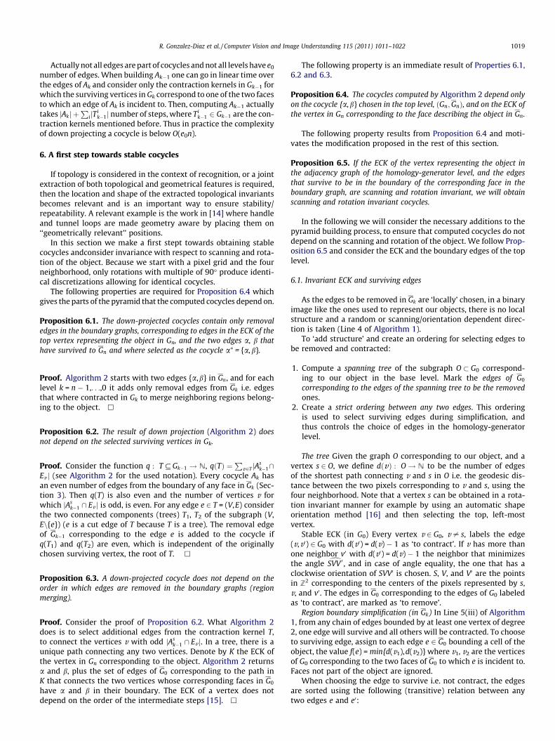
Actually not all edges are part of cocycles and not all levels have e0
number of edges. When building Ak�1 one can go in linear time overthe edges of Ak and consider only the contraction kernels in Gk�1 forwhich the surviving vertices in Gk correspond to one of the two facesto which an edge of Ak is incident to. Then, computing Ak�1 actuallytakes jAkj þ
PijT
ik�1j number of steps, where Ti
k�1 2 Gk�1 are the con-traction kernels mentioned before. Thus in practice the complexityof down projecting a cocycle is below O(e0n).
6. A first step towards stable cocycles
If topology is considered in the context of recognition, or a jointextraction of both topological and geometrical features is required,then the location and shape of the extracted topological invariantsbecomes relevant and is an important way to ensure stability/repeatability. A relevant example is the work in [14] where handleand tunnel loops are made geometry aware by placing them on‘‘geometrically relevant’’ positions.
In this section we make a first stept towards obtaining stablecocycles andconsider invariance with respect to scanning and rota-tion of the object. Because we start with a pixel grid and the fourneighborhood, only rotations with multiple of 90� produce identi-cal discretizations allowing for identical cocycles.
The following properties are required for Proposition 6.4 whichgives the parts of the pyramid that the computed cocycles depend on.
Proposition 6.1. The down-projected cocycles contain only removaledges in the boundary graphs, corresponding to edges in the ECK of thetop vertex representing the object in Gn, and the two edges a, b thathave survived to Gn and where selected as the cocycle a⁄ = {a,b}.
Proof. Algorithm 2 starts with two edges {a,b} in Gn, and for eachlevel k = n � 1,. . .,0 it adds only removal edges from Gk i.e. edgesthat where contracted in Gk to merge neighboring regions belong-ing to the object. h
Proposition 6.2. The result of down projection (Algorithm 2) doesnot depend on the selected surviving vertices in Gk.
Proof. Consider the function q : T # Gk�1 ! N, qðTÞ ¼P
v2T jAsk�1\
Ev j (see Algorithm 2 for the used notation). Every cocycle Ak hasan even number of edges from the boundary of any face in Gk (Sec-tion 3). Then q(T) is also even and the number of vertices v forwhich jAs
k�1 \ Ev j is odd, is even. For any edge e 2 T = (V,E) considerthe two connected components (trees) T1, T2 of the subgraph (V,En{e}) (e is a cut edge of T because T is a tree). The removal edgeof Gk�1 corresponding to the edge e is added to the cocycle ifq(T1) and q(T2) are even, which is independent of the originallychosen surviving vertex, the root of T. h
Proposition 6.3. A down-projected cocycle does not depend on theorder in which edges are removed in the boundary graphs (regionmerging).
Proof. Consider the proof of Proposition 6.2. What Algorithm 2does is to select additional edges from the contraction kernel T,to connect the vertices v with odd jAs
k�1 \ Ev j. In a tree, there is aunique path connecting any two vertices. Denote by K the ECK ofthe vertex in Gn corresponding to the object. Algorithm 2 returnsa and b, plus the set of edges of G0 corresponding to the path inK that connects the two vertices whose corresponding faces in G0
have a and b in their boundary. The ECK of a vertex does notdepend on the order of the intermediate steps [15]. h
The following property is an immediate result of Properties 6.1,6.2 and 6.3.
Proposition 6.4. The cocycles computed by Algorithm 2 depend onlyon the cocycle {a,b} chosen in the top level, ðGn;GnÞ, and on the ECK ofthe vertex in Gn corresponding to the face describing the object in Gn.
The following property results from Proposition 6.4 and moti-vates the modification proposed in the rest of this section.
Proposition 6.5. If the ECK of the vertex representing the object inthe adjacency graph of the homology-generator level, and the edgesthat survive to be in the boundary of the corresponding face in theboundary graph, are scanning and rotation invariant, we will obtainscanning and rotation invariant cocycles.
In the following we will consider the necessary additions to thepyramid building process, to ensure that computed cocycles do notdepend on the scanning and rotation of the object. We follow Prop-osition 6.5 and consider the ECK and the boundary edges of the toplevel.
6.1. Invariant ECK and surviving edges
As the edges to be removed in Gk are ‘locally’ chosen, in a binaryimage like the ones used to represent our objects, there is no localstructure and a random or scanning/orientation dependent direc-tion is taken (Line 4 of Algorithm 1).
To ‘add structure’ and create an ordering for selecting edges tobe removed and contracted:
1. Compute a spanning tree of the subgraph O � G0 correspond-ing to our object in the base level. Mark the edges of G0
corresponding to the edges of the spanning tree to be the removedones.
2. Create a strict ordering between any two edges. This orderingis used to select surviving edges during simplification, andthus controls the choice of edges in the homology-generatorlevel.
The tree Given the graph O corresponding to our object, and avertex s 2 O, we define dðvÞ : O! N to be the number of edgesof the shortest path connecting v and s in O i.e. the geodesic dis-tance between the two pixels corresponding to v and s, using thefour neighborhood. Note that a vertex s can be obtained in a rota-tion invariant manner for example by using an automatic shapeorientation method [16] and then selecting the top, left-mostvertex.
Stable ECK (in G0) Every vertex v 2 G0, v – s, labels the edge(v,v0) 2 G0 with d(v0) = d(v) � 1 as ‘to contract’. If v has more thanone neighbor v0 with d(v0) = d(v) � 1 the neighbor that minimizesthe angle dSVV 0 , and in case of angle equality, the one that has aclockwise orientation of SVV0 is chosen. S, V, and V0 are the pointsin Z2 corresponding to the centers of the pixels represented by s,v, and v0. The edges in G0 corresponding to the edges of G0 labeledas ‘to contract’, are marked as ‘to remove’.
Region boundary simplification (in Gk) In Line 5(iii) of Algorithm1, from any chain of edges bounded by at least one vertex of degree2, one edge will survive and all others will be contracted. To chooseto surviving edge, assign to each edge e 2 G0 bounding a cell of theobject, the value f(e) = min{d(v1),d(v2)} where v1, v2 are the verticesof G0 corresponding to the two faces of G0 to which e is incident to.Faces not part of the object are ignored.
When choosing the edge to survive i.e. not contract, the edgesare sorted using the following (transitive) relation between anytwo edges e and e0:

Fig. 12. Example showing (top) normal and (bottom) rotation invariant cocycles. The cocycles are down-projected starting with the surviving edge of the outer boundary andthe surviving edge of the (a) large and (b) small holes.
Fig. 13. (a) Original image; (b) in bold, the paths in the RAG G0 associated to the down-projected cocycles related to the holes representing the top-left and top-rightwindows.
1020 R. Gonzalez-Diaz et al. / Computer Vision and Image Understanding 115 (2011) 1011–1022
� f(e) vs. f(e0);� if f(e) = f(e0) then use the orientation of c(e)Sc(e0) vs. the orienta-
tion of c(e0)S c(e), where cðeÞ; cðe0Þ 2 R2 are the centers of theedges e and e0, and S 2 Z2 is the center of the pixel used to definethe rotation invariant tree;� if c(e)S c(e0) are collinear, the Euclidean distance between c(e)
and S vs. the Euclidean distance between c(e0) and S.
Homology-generator level When building the homology-genera-tor level, all edges of Gn�1 bounding the face of the object are sortedbased on the criteria above. Edges are selected in inverse order andused to create the spanning tree to be contracted. Edges not bound-ing the face corresponding to the object are added in random order.
Fig. 12 shows an example object and its computed cocycles withand without the rotation invariant pyramid. Figs. 13 and 14 showthe paths in the RAG associated to the down-projected cocyclesof the test images in [12]. Fig. 15 is another example showingthe path in the RAG G0 associated to the down-projected cocyclerelated to the hole associated to the ball. Finally, Fig 16 showsthe down-projected cocycles computed on a image from the2010 World Cup final in South Africa.
3 Would give Euclidean rotation robust cocycles.
6.2. Discussion
Besides stability with respect to geometric transformations, onecould consider additional criteria like the minimality of theobtained cocycles w.r.t. additional measures, like for example the
number of edges of each cocycle, the sum of the number of edgesof a basis of representative cocycles, the length of the path in R2
passing through the support squares of the pixels having at leastone cocycle in their boundary,3 etc.
It has been shown for homology generators [17] that in generalthe problem of computing minimal representative cycles is NP-hard. Nevertheless, in certain cases, like computing (n � 1)-cyclesfor n dimensional objects, finding minimal cycles is not NP-hard.For cocycles such a study does not exist yet, but considering therelation between homology and cohomology, similar results canbe expected. In the case of 2D objects, the problem of finding cocy-cles with minimal number of edges can be related to the problemof finding in the RAG shortest paths that connect vertices adjacentto different holes – this problem can be solved in nlogn if usingDijkstra’s algorithm [18].
Real life objects are typically obtained by using scanning de-vices of different type: 3D scanners, video cameras, CT, MRI, etc.One common issue in all these cases is the presence of noise andbeing robust w.r.t. the possible deformations of a real object. A pos-sible solution could be to define a robust basis of cocycles based ona function like the eccentricity transform [19] which is known tobe robust w.r.t. noise and deformations. The eccentricity transformassociates to each point of a shape the geodesic distance to thepoint furthest away. For a given starting point the geodesicdistance function defines behind holes a set of points called the

Fig. 14. (a) Original image; (b) in bold, the paths in the RAG G0 associated to the down-projected cocycles.
Fig. 15. In bold, the path in the RAG G0 associated to the down-projected cocycle.
R. Gonzalez-Diaz et al. / Computer Vision and Image Understanding 115 (2011) 1011–1022 1021
cut locus which can be reached in the same distance on multiplepaths (going on both sides of the hole). In many cases, cutting ashape along these sets can produce a shape with less holes, whichgives the same geodesic distance function for the same startingpoint. The eccentricity transform can be interpreted as the maxi-mum over multiple geodesic distance propagations initiated at
Fig. 16. On the top-left, original image (a image from the 2010 Wor
each point of the shape. As cocycles can be seen as ‘cuts into theobject’ that ‘kill’ a hole, a cut which has the minimum effect onthe eccentricity transform, could provide an avenue for selectingrobust cocycles.
Finding associations between concepts in cohomology andgraph theory will open the door for applying existing efficient algo-rithms (e.g. shortest path). The following lemma can be seen as afirst step in this direction.
Lemma 6.6. Any set of foreground edges in the boundary graph G0,associated to a path in the RAG G0, connecting a hole Oi of the objectwith the (outside) background face, is a representative 1-cocyclecohomologous to the down projection of the 1-cocycle a�i . It blocks anygenerator that would surround the hole.
In other words, consider the down projection [12] of ai and b in G0:the 1-cycles i1(ai) = a and i1(b) = b, respectively. Take any edge ea 2 aand eb 2 b. Let fa, fb be faces of K0, the boundary cell complexassociated to the foreground in G0 having ea, respectively eb, in theirboundary. Let v0, v1, . . ., vn be a simple path of vertices in G0 s.t. allvertices are labeled as foreground. v0 is the vertex associated to fa, and
ld Cup final in South Africa); in bold, down-projected cocycles.

1022 R. Gonzalez-Diaz et al. / Computer Vision and Image Understanding 115 (2011) 1011–1022
vn to fb.Consider the set of edges c = {e0, . . . , en+1} of G0, where e0 = ea,en+1 = eb, and e‘, ‘ = 1, . . ., n, is the common edge of the regions in G0
associated with the vertices vi�1 and vi. c defines a 1-cocyclecohomologous to the down projection of the 1-cocycle a�i .
Proof. c is a 1-cocycle iff c@2 is the null homomorphism. First,c@2(f‘) = c(e‘ + e‘+1) = 1 + 1 = 0. Second, if f is a 2-cell of K0, f – f‘,‘ = 0, . . . ,n, then, c@(f) = 0. To prove that the cocycles c and a�i p1
(the down projection of a�i to the base level of the pyramid) arecohomologous, is equivalent to prove that ci1 ¼ a�i . We have thatci1(a) = c(eb) = 1 and ci1(b) = c(ea) = 1. Finally, ci1 over the remain-ing self-loops of the boundary graph of the homology-generatorlevel is null. Therefore, ci1 ¼ a�i . h
7. Conclusion
This paper considers cohomology in the context of graph pyra-mids. Representative cocycles are computed at the reduced top le-vel and down projected to the base level corresponding to theoriginal image. Connections between cohomology and graph the-ory are proposed, considering the application of cohomology inthe context of classification and recognition. The current paper ex-tends the previous work with detailed insights and proofs, and arefinement of the previous method that makes the obtained cocy-cles scanning and rotation invariant. Extension to higher dimen-sions, where cohomology has a richer algebraic structure thanhomology, and complete cohomology – graph theory associationsare proposed for future work. For this last task, we could considernD generalized map pyramids [20].
Acknowledgments
This work was partially supported by the Austrian Science Fundunder Grants S9103-N13 and P18716-N13 and Junta de AndalucíaGrant FQM-296. We thank the anonymous reviewers for theircomments.
References
[1] Z.J. Wood, H. Hoppe, M. Desbrun, P. Shroder, Removing excess topology fromisosurfaces, ACM Trans. Graph. 23 (2) (2004) 190–208.
[2] M. Allili, D. Corriveau, Topological analysis of shapes using morse theory,Comput. Vis. Image Underst. 105 (3) (2007) 188–199.
[3] A. Hatcher, Algebraic Topology, Cambridge University Press, 2002.[4] R. Gonzalez-Diaz, A. Ion, M. Iglesias-Ham, W.G. Kropatsch, Irregular graph
pyramids and representative cocycles of cohomology generators, in: A.Torsello, F. Escolano, L. Brun (Eds.), Proceedings of the 7th IAPR-TC15International Workshop on Graph-based Representations in PatternRecognition, LNCS, vol. 5534, Springer, Venice, Italy, 2009, pp. 263–272.
[5] R. Diestel, Graph Theory, Graduate Texts in Mathematics, vol. 173, Springer,1997.
[6] W.G. Kropatsch, Building irregular pyramids by dual graph contraction, IEE-Proceedings of Vision, Image and Signal Processing 142 (6) (1995) 366–374.
[7] W.G. Kropatsch, C. Reither, D. Willersinn, G. Wlaschitz, The dual irregularpyramid, in: Dmitry Chetverikov, Walter G. Kropatsch (Eds.), Proceedings ofCAIP’93, Computer Analysis of Images and Patterns, Lecture Notes in ComputerScience, vol. 719, Springer, 1993, pp. 31–40.
[8] D. Willersinn, W.G. Kropatsch, Dual graph contraction for irregular pyramids,in: Shmuel Peleg, Shimon Ullman, Yehezkel Yeshurun (Eds.), ICPR1994:Proceedings of the 12th IAPR International Conference on PatternRecognition, vol. 3, IEEE Comp. Soc., 1994, pp. 251–256.
[9] W.G. Kropatsch, Y. Haxhimusa, Z. Pizlo, G. Langs, Vision pyramids that do notgrow too high, Pattern Recogn. Lett. 26 (3) (2005) 319–337.
[10] J.R. Munkres, Elements of Algebraic Topology, Addison-Wesley, 1993.[11] R. Gonzalez-Diaz, M.J. Jimenez, B. Medrano, H. Molina-Abril, P. Real, Integral
operators for computing homology generators at any dimension, in: 13thIberoamerican Congress on Pattern Recognition (CIARP 2008), LNCS, vol. 5197,Springer, 2008, pp. 356–363.
[12] S. Peltier, A. Ion, W.G. Kropatsch, G. Damiand, Y. Haxhimusa, Directlycomputing the generators of image homology using graph pyramids, ImageVis. Comput. 27 (7) (2009) 846–853.
[13] M. Iglesias-Ham, A. Ion, W.G. Kropatsch, E.B. García, Delineating homologygenerators in graph pyramids, in: 13th Iberoamerican Congress on PatternRecognition (CIARP 2008), LNCS, vol. 5197, Springer, 2008, pp. 576–584.
[14] T.K. Dey, K. Li, J. Sun, D. Cohen-Steiner, Computing geometry-aware handleand tunnel loops in 3d models, ACM Trans. Graph. 27 (3) (2008) 1–9.
[15] W.G. Kropatsch, Equivalent contraction kernels to build dual irregularpyramids, Adv. Comput. Sci. Adv Comput. Vis. (1997) 99–107.
[16] J.D. Zunic, L. Kopanja, J.E. Fieldsend, Notes on shape orientation where thestandard method does not work, Pattern Recogn. 39 (5) (2006) 856–865.
[17] C. Chen, D. Freedman, Hardness results for homology localization, in:Proceedings of the Annual ACM-SIAM Symposium on Discrete Algorithms(SODA), 2010, pp. 1594–1604.
[18] M.J. Atallah (Ed.), Algorithms and Theory of Computation Handbook, first ed.,CRC-Press, 1998.
[19] A. Ion, W.G. Kropatsch, E. Andres, Euclidean eccentricity transform by discretearc paving, in: D. Coeurjolly, I. Sivignon, L. Tougne, F. Dupont (Eds.), 14th IAPRInternational Conference on Discrete Geometry for Computer Imagery (DGCI),Lecture Notes in Computer Science, vol. LNCS 4992, Springer, Lyon, France,2008, pp. 213–224.
[20] C. Grasset-Simon, G. Damiand, P. Lienhardt, nd generalized map pyramids:definition, representations and basic operations, Pattern Recogn. 39 (4) (2006)527–538.