Embed Size (px)
Citation preview

RSC Advances
PAPER
Ope
n A
cces
s A
rtic
le. P
ublis
hed
on 1
1 Ja
nuar
y 20
19. D
ownl
oade
d on
12/
22/2
021
1:16
:41
AM
. T
his
artic
le is
lice
nsed
und
er a
Cre
ativ
e C
omm
ons
Attr
ibut
ion-
Non
Com
mer
cial
3.0
Unp
orte
d L
icen
ce.
View Article OnlineView Journal | View Issue
Computer simula
State Key Laboratory of Supramolecular
Theoretical and Computational Chemistry,
University, Changchun 130023, China. E-m
† Electronic supplementary informa10.1039/c8ra09635j
Cite this: RSC Adv., 2019, 9, 1354
Received 23rd November 2018Accepted 2nd January 2019
DOI: 10.1039/c8ra09635j
rsc.li/rsc-advances
1354 | RSC Adv., 2019, 9, 1354–1361
tion study on the self-assembly oftethered nanoparticles with tunable shapes†
Sheng-Fang Lu, Bing-Yu Li, Yan-Chun Li * and Zhong-Yuan Lu
We built a tethered nanoparticle (TNP) model that is composed of a nanoparticle with a hydrophobic
tethered polymer chain. The shape of the nanoparticle can be tuned from a pure rigid cube to a soft
sphere, mimicking the increase of grafting density on the nanocube surfaces. With this model, we study
the self-assembly of TNPs in dilute solution using a dissipative particle dynamics simulation technique,
and especially focus on the influence of particle shape, tethered chain length, and grafting density on
the self-assembly structures. Some intriguing aggregates such as spherical micelles, pearl-necklace-like
structures, cubic columnar structures, handshake structures, core–shell–corona micelles, and four-
patch micelles have been observed when varying the interactions between cubes and solvents and the
lengths of tethered chain. Modifying the nanocube surface with some hydrophilic grafted chains helps
the TNPs form small micelles. Increased steric repulsion due to chain overlapping at larger grafting
densities results in shape transformation of the nanoparticle from a rigid cube to a soft sphere. In these
cases, the self-assembled structures are characterized by the packing of nanoparticles on the micelle
surface, and the typical packing mode turns from rectangular (typical for cubes) to hexagonal (typical for
spheres).
1 Introduction
Tethered nanoparticles (TNPs)1 composed of chemicallydistinct and geometrically anisotropic building blocks providea promising strategy for bottom-up material design. TNPs areusually composed of “so chains” and a shape-persistent “rigidhead” (i.e., nanoparticle). For example, a unique type of TNPs,called “surfactant-like giant molecules” that possess a polarionic head tethered with a exible hydrophobic chain,2–4 can beregarded as the size-amplied version of small molecules sincethey capture the structural feature of small molecules butpossess a large size.2–4 For the TNP system, various shapes,distinct symmetry, and topology are considered as very impor-tant parameters to control their self-assembly process. A widevariety of TNP self-assembly structures have been reported withpotential applications in functional materials5,6 andnanodevices.7–9
Nanoparticles with various shapes such as sphere,10 rod,11
and cube,12 provide many possibilities to study geometricaleffects of rigid nanoparticles on their self-assembly. Cheng andcoworkers13,14 synthesized a class of giant molecules by attach-ing acid-functionalized polyhedral oligomeric silsesquioxane(APOSS) or carboxylic acid-functionalized fullerene (AC60) onto
Structure and Materials, Laboratory of
Institute of Theoretical Chemistry, Jilin
ail: [email protected]
tion (ESI) available. See DOI:
so polymer chains based on click chemistry. They demon-strated a route to control the self-assembly of the PS-APOSS witha hydrophilic head and hydrophobic tail. The self-assembledmorphology of PS-APOSS can evolve from vesicles to wormlikecylinders and further to spheres as the degree of ionization ofthe carboxylic acid groups is increased.10 Furthermore, they alsofocused on phase separation behaviour of two series of shapeamphiphiles PSn-AC60 and 2PSn-AC60. A number of self-assembled micellar structures can be obtained by changingmolecular topology, polymer tail length, and initial molecularconcentration.14 Computer simulation, as a link betweenexperiments and theory, can provide reasonable predictions toself-assembly structures of TNPs.15,16 It is not surprising thatmany exotic self-assembled structures of TNPs have been re-ported by using simulations.1,17,18 Glotzer and coworkers pio-neeringly performed a series of Brownian dynamics simulationsabout self-assembly of TNPs. Specically, TNP with differentshapes of head groups such as sphere, cube, rod, and triangle,as well as functionalized with different number or topology ofchains, has been investigated.19–24 They explored the packingconstraints due to the nanoparticle geometry and found thatsuch systems have much richer self-assembly structures thantraditional block copolymers. Wang and coworkers used dissi-pative particle dynamics (DPD) simulation method to study theself-assembly behaviour of TNP amphiphiles.25,26 By varying theinteraction between nanoparticle heads and solvents, the size ofthe nanoparticles, the length and the number of the chains,they obtained sphere like micelles, pomegranate-like micelles,
This journal is © The Royal Society of Chemistry 2019

Paper RSC Advances
Ope
n A
cces
s A
rtic
le. P
ublis
hed
on 1
1 Ja
nuar
y 20
19. D
ownl
oade
d on
12/
22/2
021
1:16
:41
AM
. T
his
artic
le is
lice
nsed
und
er a
Cre
ativ
e C
omm
ons
Attr
ibut
ion-
Non
Com
mer
cial
3.0
Unp
orte
d L
icen
ce.
View Article Online
hierarchical colloidal polymeric structures, disklike micelles,vesicles, and so on.
Beneted from the booming synthesis techniques, the shapeand size of many nanoparticles can change in response toexternal stimuli and molecular input.27 For example, Yoo andMitragotri synthesized poly(lactide-co-glycolide) particles whoseshape switch can be controlled by temperature, pH, andchemical additives.28 Gang and coworkers29 graed dodeca-nethiol ligand chains on cubic palladium nanoparticles, andthese ligand chains form a so shell on the nanoparticlesurface. They adopted a reconguration process via solventevaporation. The lattice packing changed with the shape ofnanoparticle that continuously transforms from cubic to quasi-sphere. Some simulations have also been used to study theordered packing of nanoparticle systems, in which the shapeevolution of nanoparticles can be described explicitly. Ni et al.30
built the phase diagram of colloidal hard superballs, whoseshape interpolates between cubes and octahedra via spheres.Glotzer and coworkers31,32 obtained many exotic crystal struc-tures based on nanoparticle model through geometry-drivenself-assembly approaches and conrmed that ordered packingcan form via different shape-shiing processes.
Since the nanoparticle head of a TNP is normally protectedwith ligand chains during fabrication, the possible stimuli–response of ligand chains may effectively change the shape ofTNP head and consequently inuence the self-assembly ofTNPs. Unfortunately, the effect of shape of TNPs and corre-sponding shape variation on their self-assembly structures hasnot been systematically studied, even though such an effect isapparently unique for TNPs. For a better understanding of theself-assembly behaviour of TNP in shape-changing process,a suitable model is needed. However, there have been nosimulation model and studies available considering shape-changing of TNP. In this study, we have established a TNPmodel in which the variation of the head of TNP can be takeninto account, to implicitly mimic the important inuence ofligand chains. With this model, we used dissipative particledynamics to study (i) the self-assembly of tethered nanocubes inselective solvent, and (ii) the effect of shape-changing of TNPheads on the packing and aggregation of TNPs.
2 Model and simulation method
Our model is shown in Fig. 1. A TNP consists of a exiblepolymer chain monotethered on a so-shell nanoparticle. The
Fig. 1 The model of a TNP consists of a soft-shell nanoparticle anda tethered polymer chain. The semitransparent yellow beads (G)represent the soft shell of the nanoparticle, and correspondinglycontrol the nanoparticle shape, the green beads (A) represent thecube, and the blue beads (B) represent the polymer chain.
This journal is © The Royal Society of Chemistry 2019
green beads are named type A beads. The outermost eight Abeads locate at the eight vertices of the cube. The semi-transparent yellow beads are named type G beads, whichshape up the so shell.
Dissipative particle dynamics (DPD) as a coarse-grainedsimulation method allows larger time and length scale simu-lations and takes into account the effect of hydrodynamics. Itwas introduced in 1992 by Hoogerbrugge and Koelman33 andhad been widely used in studies of self-assembly of so mattersystems. In DPD, a coarse-grained bead represents a group ofatoms, and all of the DPD beads obey the Newton's equations ofmotion:34
dri
dt¼ vi mi
dvi
dt¼ fi; (1)
in which ri is the position of the bead i, vi is the velocity of thebead i,mi is themass of the bead i, and fi is the sum of the forcesacting on the bead i. In the simulation, the interaction cutoff,the bead mass and the energy kBT are set to be unity, i.e., rc ¼ m¼ kBT¼ 1, so the time unit s ¼ ffiffiffiffiffiffiffiffiffiffiffiffiffiffiffiffiffiffi
mrc=kBTp ¼ 1: Actually, we have
considered a generic model for polymer tethered nanoparticles;a description on the length, time and temperature scales isshown in ESI.† The bead i receives a total of three forces: theyare conservative force FCij, dissipative force F
Dij and random force
FRij:
fi ¼Xisj
�FCij þ FD
ij þ FRij
�: (2)
These forces act on pairs of beads i and j. They are given by:
FCij ¼ aiju
C(rij)eij, (3)
FDij ¼ �guD(rij)(vijeij)eij, (4)
FRij ¼ suR(rij)xijDt
�1/2eij, (5)
in which, rij ¼ ri � rj, rij ¼ |rij|, eij ¼ rij/rij, vij ¼ vi � vj, and xij isthe random variable with zero mean and unit variance, g is thefriction coefficient related to the dissipative force. The dissi-pative force and random force couple together to form thethermostat. uC(rij) is a weight function depending on r. Weusually choose: uC(rij) ¼ 1 � rij/rc for rij/rc < 1 and uC(rij) ¼ 0 forrij/rc > 1. According to Espanol and Warren,35 uD(rij), u
R(rij), sand g satisfy the relations:
uD(r) ¼ [uR(r)]2, (6)
s2 ¼ 2gkBT. (7)
The beads on each tethered polymer chain are connected byharmonic springs with FS
i ¼ PjCðrij � reÞ; in which the spring
constant C and the equilibrium bond length re are respectivelyset to 120 and 0.86 to ensure the bond length distribution iswithin a reasonable range.
Since in DPD simulations “so bead” model is generallyadopted, it is inevitable that there is bead overlapping and bond
RSC Adv., 2019, 9, 1354–1361 | 1355
RSC Advances Paper
Ope
n A
cces
s A
rtic
le. P
ublis
hed
on 1
1 Ja
nuar
y 20
19. D
ownl
oade
d on
12/
22/2
021
1:16
:41
AM
. T
his
artic
le is
lice
nsed
und
er a
Cre
ativ
e C
omm
ons
Attr
ibut
ion-
Non
Com
mer
cial
3.0
Unp
orte
d L
icen
ce.
View Article Online
crossing in dynamic process, which is however unreasonable inthe real system. It may result in problems especially whendescribing nanoparticles in DPD simulations. In order toensure that rigid nanoparticles can be reasonably described inour simulations, we use a modied DPD potential between Abeads to construct the cubes, in which a rigid core is added toeach A bead by redening the conservative force so that beadscannot penetrate each other. Moreover, we further add a smallcube in the centre of cubic head. This double-layered nestedstructure ensures rigid heads cannot overlap and the chaincannot enter the interior of the rigid body. The modiedconservative force in DPD is:36
FCij ¼
8<:
Fmaxeij rij\2rsaij
�1� rij
�rc�eij 2rs # rij # rc
0 rij . rc
: (8)
rs and Fmax are hard core radius and force parameter, respec-tively. Fmax brings a large but nite potential barrier to theoverlapping beads. rs ¼ 0.3 and Fmax ¼ 100 are used in oursimulations. We have used radial distribution function (RDF) toprove there is indeed no overlapping between cubes as shown inESI Fig. S1.†
In the simulation, polymer chains are modeled hydrophobicand the cubes are hydrophilic. The DPD interaction parametersare shown in Table 1.
Here the interaction parameter between the same type ofbeads aii is set as 25. The conservative interaction strength aij
can be mapped to Flory–Huggins c-parameter at r ¼ 3:34
aij z aii + 3.27cij. (9)
The simulation box size is 40 � 40 � 40. The side length ofcube is 0.78rc. In order to maintain the temperature of thesimulation, the simulation timestep is set to dt ¼ 0.008. Eachsimulation undergoes at least 5 � 106 steps for equilibrium.The concentration of the system is f ¼ 0.05, as dened by
f ¼ NC � Vcube þNC � LC � VC
NC � Vcube þNC � LC � VC þNS � VS
(10)
NC, LC, NS are the numbers of nanocubes, beads in polymerchains, and solvent beads, respectively. Vcube, VC, VS are thevolumes of rigid cubic heads, beads in polymer chains, andsolvent beads, respectively. The details on the number and sizeof bead in each simulation box are shown in ESI Table S1.†
G beads correspond to a bunch of ligand chains graing onthe surface of rigid cubic head, thus our nanoparticle is similarto the one reported by Gang and coworkers.29 The shape of TNPcan be tuned by adjusting the interaction between G beads. Inan extreme condition that aGG ¼ 0, the graing density is 0 andthe nanoparticle is simply a nanocube. With the increase of the
Table 1 The interaction parameters of tethered nanocubes
A B S
A 25 55 aASB 55 25 50S aAS 50 25
1356 | RSC Adv., 2019, 9, 1354–1361
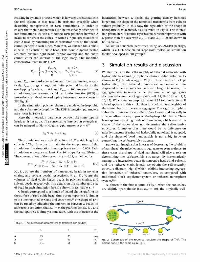
interaction between G beads, the graing density becomeslarger and the shape of the nanohead transforms from cube tosphere gradually. In this way, the regulation of the shape ofnanoparticles is achieved, as illustrated in Fig. 2. The interac-tion parameters of double-layer nested cubic nanoparticles withG particles in the case with aGG ¼ 0 and aAS ¼ 50 are shown inESI Table S2.†
All simulations were performed using GALAMOST package,which is a GPU-accelerated large-scale molecular simulationtoolkit developed in our group.37
3 Simulation results and discussion
We rst focus on the self-assembly of tethered nanocube withhydrophilic head and hydrophobic chain in dilute solution. Asshown in Fig. 3, when aAS ¼ 25 (i.e., the cubic head is kepthydrophilic), the tethered nanocubes self-assemble intodispersed spherical micelles. As chain length increases, theaggregate size increases while the number of aggregatesdecreases (the number of aggregates is 49, 28, 16, 10 for n¼ 3, 5,10, 15). We choose an empirical value 1.25 to draw a circle. Ifa bead appears in this circle, then it is dened as a neighbor ofthe center bead in the same aggregate. The rigid hydrophiliccubes distribute on the micelle surface loosely and basically inan equal-distance way to protect the hydrophobic chains. Thereis no apparent packing mode of these cubes, which means theshape of the cubes does not determine the self-assemblystructures. It implies that there would be no difference onmicelle structure if spherical hydrophilic nanohead is adopted,and the shape of head nanoparticle is not a big issue oncontrolling the self-assembly structure.
But we can imagine that in cases of decreasing the solubilityof nanohead, the micelles start to aggregate or even coalesce. Inthese cases the shape of rigid nanohead will play a role ondetermining the self-assembly structures. By systematicallyvarying the interaction between nanocube heads and solventsand the tethered chain length, we obtain the self-assemblystructure diagram (Fig. 4) which exhibits interesting aggrega-tion behaviour of tethered nanocubes, as compared withtraditional block copolymer system or tethered nanospheresystem.25,26
As shown in the rst column of Fig. 4, when the nanocubesare slightly hydrophobic (i.e., aAS ¼ 30), the originally well-
Fig. 2 Schematic of the route to regulate the shape of TNP. Thecolour code is the same as in Fig. 1.
This journal is © The Royal Society of Chemistry 2019

Fig. 3 Self-assembled structures with different chain lengths at aAS ¼25. (a) n ¼ 3, (b) n ¼ 5, (c) n ¼ 10, (d) n ¼ 15. The solvent beads are notshown for clarity. The colour code is the same as in Fig. 1.
Paper RSC Advances
Ope
n A
cces
s A
rtic
le. P
ublis
hed
on 1
1 Ja
nuar
y 20
19. D
ownl
oade
d on
12/
22/2
021
1:16
:41
AM
. T
his
artic
le is
lice
nsed
und
er a
Cre
ativ
e C
omm
ons
Attr
ibut
ion-
Non
Com
mer
cial
3.0
Unp
orte
d L
icen
ce.
View Article Online
dispersed micelles start to aggregate to form pearl-necklace-likestructures38 and the distance between nanocubes decreases.More structural details are shown in ESI Fig. S2.† We alsoexamine the stability of these structures by mimicking anneal-ing process in all DPD simulations. We rst increase thetemperature to T ¼ 2.5, at which the pearl-necklace-like struc-ture disappears and only some small micelles exist in thesolution; then we decrease the temperature back to T ¼ 1.0slowly by 0.1 per 5� 105 time steps. Aer the annealing process,the dispersed micelles re-aggregate into pearl-necklace-likestructures quite similar to those obtained in direct simula-tions, which means the structures shown in the rst column ofFig. 4 are the equilibrium structures at the correspondingthermodynamic condition. Similar structures have been
Fig. 4 Self-assembly structure diagram of tethered nanocubes. Thehorizontal axis represents the interaction between beads in cubic headand solvent, the vertical axis represents the chain length. The colourcode is the same as in Fig. 1. The structures highlighted in red squarewill be shown in Fig. 5 with more details.
This journal is © The Royal Society of Chemistry 2019
observed in experiments.39–41 This type of structure obtained inour simulations is related to the stable interface formed by rigidnanocubes. The packing of the nanocubes on the surface ofmicelles slows down the surfactant exchange between micellesand the corresponding structure rearrangement; therefore thepearl-necklace-like structure can be stably formed as shown themovie in ESI.†
When the interaction parameter aAS further increases to 40,the nanocube is more hydrophobic. The corresponding self-assembly structures are shown in the second column of Fig. 4.It should be noted that when the whole self-assembly buildingblock is hydrophobic enough (in our case when aAS>30), theequilibrium self-assembly structures can only be obtained aerannealing in our simulations. In a typical annealing simulation,aer initial equilibration, temperature is increased to T¼ 2.0 topartially destroy the original self-assembly structures. Then thetemperature is decreased to T ¼ 1.0 slowly by 0.1 per 5 � 105
time steps. Aer that, at least 1 � 106 time steps simulation isperformed to obtain the self-assembly structures. In all thesefour structures shown in the second column of Fig. 4, thenanocubes are packing tightly and surrounding the hydro-phobic chains. When the chain is short (n ¼ 3, 5), the self-assembly structures are greatly affected by the shape of nano-cubes: the rigid cubic heads are packing in face-to-face mannerand form the framework of columnar structures (as shown themovie in ESI†), while the tethered chains distribute in thechannels of the framework, similar to the structure obtained inexperiments.42 Obviously, the diameter of the channel in thecase of n ¼ 3 is smaller than that in the case of n ¼ 5, whichimplies that it is possible to tune the chain length and type tocontrol the channel size and interior property, and the corre-sponding material may be used as responsive lters. Theseframework structures are still quite stable in higher concen-trations. For example, as shown in ESI Fig. S3,† we obtainhexagonally arranged columnar structures imbedded inframework formed by nanocubes when the concentrationincreases to 0.07 for n ¼ 5. The stability of the self-assemblystructures is endowed with the shape and volume persistenceof the nanocube.43,44 When tethered chain length increases to n¼ 10, we obtain the handshake structure,45 in which the outershells formed by nanocubes possess different orientations. Acore–shell–corona micelle is obtained in case of n ¼ 15, inwhich core, shell, and corona are composed of nanocube,tethered chain, and nanocube, respectively. The formation ofthese two structures is due to the compromise between bendingrigidity of layer structure formed by nanocubes favoringa planar conguration and surface tension of the whole struc-ture favoring a spherical conguration.
The third column of Fig. 4 shows the self-assembly struc-tures obtained in the cases with aAS ¼ 50. Some details ontypical structures viewing in different directions are shown inFig. 5. In this situation, in the competition between bendingrigidity and surface tension, the latter has more inuence ondetermining the self-assembly structures. Therefore, the ob-tained self-assembly structures are more spherical, and thepacking of nanocubes is more ordered (Fig. 5). Since it isimpossible to perfectly tessellate spherical surface with squares,
RSC Adv., 2019, 9, 1354–1361 | 1357

RSC Advances Paper
Ope
n A
cces
s A
rtic
le. P
ublis
hed
on 1
1 Ja
nuar
y 20
19. D
ownl
oade
d on
12/
22/2
021
1:16
:41
AM
. T
his
artic
le is
lice
nsed
und
er a
Cre
ativ
e C
omm
ons
Attr
ibut
ion-
Non
Com
mer
cial
3.0
Unp
orte
d L
icen
ce.
View Article Online
there are naturally some packing defects on the surface of more-spherical micelles. An interesting result is shown in Fig. 5a: thecompetition between surface tension and bending rigidityresults in a four-patch micelle. This type of structure haspotential applications as mesoscopic building blocks in con-structing hierarchical three-dimensional ordered structures atlarger length scale.
The results shown in Fig. 3 and 4 clearly demonstrate theinuence of nanocube shape and solvent condition on the self-assembly structures of TNPs. In all the cases reported above, thenanocubes are free of any ligand modication; therefore thenanocube shape can have its maximum inuence on TNP self-assembly. Actually in a large amount of experiments, thenanoparticle surface is normally protected by graed ligandchains with controlled graing density. The interactionsbetween nanocubes are consequently mediated by ligandchains and adsorbed solvent molecules, which will largelyinuence the self-assembly structures of TNPs. From the coarse-grained point of view, the graed chains and adsorbed solventmolecules actually form a so shell around the rigid nanocube(ESI Fig. S4†). Also as illustrated in Fig. 2 together with Fig. S4,†it is possible to represent the effective interaction betweengraed chains by tuning the interactions between the beadsforming the so shells of two TNPs. As graing densityincreases, the graed chains are more crowded and the inter-action between graed nanocubes is more repulsive due tolarger steric repulsion between chains. Moreover, the number ofadsorbed solvent molecules in the graed chain layer becomeslesser. Therefore, when we increase aGG to represent theincreasing repulsion between so shells in cases of largergraing densities, we simultaneously increase aGS to reectmore solvent molecules are “repelled” from the graed chainlayers (ESI Fig. S4†).
Fig. 5 These structures correspond to the highlighted structures inFig. 4. (a1� a3) show core–shell–coronamicelle with four patches, (b1� b3) show the handshake structure, (c1 � c3) show the columnarstructure. The first and the second columns show structures indifferent directions. The third column shows only the nanocubes,while (b3) also shows the iso-density surface of tethered chains. Thecolour code is the same as in Fig. 1.
1358 | RSC Adv., 2019, 9, 1354–1361
We take the TNP system A1B15 in the case of aAS ¼ 50 asa reference, for which the representative self-assembly structureof TNPs with bare nanocubes (aGG ¼ 0) is shown in Fig. 5a. Wethen change aGG ¼ aGS to 5, 10, 15, 20 and 25, to represent theshape of nanocube head transform from cube to superball30
then to sphere, according to the increasing graing densities(cf. Fig. 2). Key simulation parameters are shown in Table 2, andother parameters are consistent with those used above.
Fig. 6 shows the representative self-assembly structures ofTNP system A1B15 with different interaction parametersbetween G beads as well as between G and S beads. When aGG
and aGS are small, the so shell of the TNP is more “penetrable”by other so-shell and solvent beads; it also means the so shellof TNP is more accessible to solvent, or in another word, morehydrophilic. When aGG and aGS are large, the shell beads aremore repulsive to other shell and solvent beads, and the origi-nally cubic head turns to be more spherical. As shown in Fig. 6a,in the case of aGG ¼ aGS ¼ 5 the self-assembly structure of TNPsis dispersed small spherical micelles in solution. Here thesurface of nanocube is sparsely graed with hydrophilic chains,and these so-formed hydrophilic nano-heads help to stabilizethe micelle structures. Solvent beads distributed in the graedchain layer prevent further aggregation and fusion betweensmall micelles. As aGG increases, these small micelles slowlyaggregate. It should be noted that in the cases with larger aGG,the so shell is still hydrophilic, but the eight exposed hydro-phobic nanocube corner beads take more and more inuenceon the self-assembly structures. The increase in aGG corre-sponds to more and more graed ligand chains on nanocubesurfaces, and these chains can “feel” more entropic repulsionfrom their neighbors and deviate from the unperturbed state.43
In such situation, if we see the TNP system at nanoparticle level,shells surrounding the nanocubes become harder due todensely graed ligand chains, at the same time the solventscannot penetrate into the shell region. Therefore the self-assembly process will be dominated by the hydrophobic inter-action between nanocube corner beads as illustrated in Fig. 1.The self-assembly structures turn to be larger micelles withloosely and hexagonally packed spherical nanoparticlesdistributing at the micelle surfaces (Fig. 6d and e).
In order to further explore the nanoparticle distribution atthe micelle surface, we have calculated the distances betweencenters of mass of neighboring TNP heads in each systemshown in Fig. 6. We then rank the obtained distances from thesmall to the large, i.e., for each system we rank the smallestdistance between nanoparticles the rst, then rank the secondsmallest distance the second, and so on. The results are shownin Fig. 7. Apparently, with increasing aGG the distance between
Table 2 The interaction parameters of tethered soft-shellnanoparticle
A G B S
A 25 25 55 50G 25 aGS 55 aGSB 55 55 25 50S 50 aGS 50 25
This journal is © The Royal Society of Chemistry 2019

Fig. 6 Representative self-assembly structures of TNP system A1B15
with aAS¼ 50 and (a) aGG¼ aGS¼ 5, (b) aGG¼ aGS¼ 10, (c) aGG¼ aGS¼15, (d) aGG ¼ aGS ¼ 20, and (e) aGG ¼ aGS ¼ 25. In (d) and (e), the iso-density surfaces of micelle hydrophobic cores are also shown asidethe self-assembly structures. The solvent beads are not shown forclarity. The colour code is the same as in Fig. 1. It should be noted thatfrom (a) to (e), the colour of G beads changes from light yellow toyellow, showing the soft shell turns to be more non-penetrable withincreasing grafting density on the nanocube surface.
Fig. 8 Radial distribution functions g(r) between centres of mass ofhead nanoparticles for A1B15 in the case with aAS ¼ 50. The snapshotfor the equilibrium self-assembly structure in the case of aGG ¼ 0 isshown in the inset. A parallelogram packing of nanocubes is high-lighted with read lines in the snapshot.
Paper RSC Advances
Ope
n A
cces
s A
rtic
le. P
ublis
hed
on 1
1 Ja
nuar
y 20
19. D
ownl
oade
d on
12/
22/2
021
1:16
:41
AM
. T
his
artic
le is
lice
nsed
und
er a
Cre
ativ
e C
omm
ons
Attr
ibut
ion-
Non
Com
mer
cial
3.0
Unp
orte
d L
icen
ce.
View Article Online
nanoparticles is gradually decreasing. In the case with aGG ¼ 5,the distance rcm has a broad distribution, characterizing theloosely distributed nanoparticles at micelle surfaces shown inFig. 6a. In contrast, for aGG ¼ 20 and 25 the distance rcm doesnot change much with increasing ranking from 20 to 150. Itclearly shows the close packing of nanoparticles in these twocases. Statistically, the distance rcm at the same rank is slightlylarger in the case with aGG ¼ 25 as compared to that with aGG ¼20, which is a natural result of more rigid “shell” in the casewith larger aGG. It reasonably reects that the nanoparticlesstart to repel each other when the graing density is prettylarge.
Fig. 7 The ranking of center of mass distances between neighboringhead nanoparticles. g represents the ranking of the center of massdistance of nanoparticles (the first 150 rankings are shown). rcmrepresents the center of mass distance between head nanoparticles.
This journal is © The Royal Society of Chemistry 2019
We have also calculated the radial distribution functions(RDFs) between centres of mass of head nanoparticles in thecases with different values of aGG. For aGG equal to 5, 10 and 15,the RDFs are similar to the one characterizing typical liquidstructure, reecting the fact that the hydrophilic head nano-particles are homogeneously distributed on the micellesurfaces, as illustrated in Fig. 6a–c. We then focus on RDFs fortwo extreme cases with different nanoparticle shapes, one is foraGG ¼ 25 and the corresponding self-assembly structure isshown in Fig. 6e, and the other is for aGG ¼ 0 and the corre-sponding self-assembly structure is shown in Fig. 5a. The RDFsfor these two cases are shown in Fig. 8. The rst peak positionsfor the two systems are 1.51 and 2.07, corresponding to thepacking of nanocubes and nanospheres, respectively. Appar-ently the packing of cubic head is more compact than sphericalhead. The RDF for the system of aGG ¼ 25 has a crested peaksignal,46,47 which is a clear evidence for hexagonal packing; i.e.,each nanosphere has six neighbouring spheres on a curvesurface next to it. For aGG ¼ 0, the main peaks (about at 1.51,3.01 and 4.49) satisfy the relationship of 1 : 2 : 3, characterizingthe closest packing of nanocubes. But it is interesting to seefrom Fig. 8 that two small peaks (see the arrows) appearbetween the rst and the second main peaks for aGG ¼ 0. Asillustrated in Fig. 8, the two small peaks correspond to twodiagonal lines of a parallelogram. The nanocubes are packing inthis way so that the tension due to bending of the layer can bebetter relaxed.
4 Conclusions
Using dissipative particle dynamics simulation technique, wehave studied the self-assembly of tethered nanoparticles withtunable shapes in dilute solution. In the cases that the tetherednanohead is a rigid cube, we have obtained a variety of self-assembly structures with the change of interaction betweenrigid nanocube and solvent and the length of tethered chains.
RSC Adv., 2019, 9, 1354–1361 | 1359

RSC Advances Paper
Ope
n A
cces
s A
rtic
le. P
ublis
hed
on 1
1 Ja
nuar
y 20
19. D
ownl
oade
d on
12/
22/2
021
1:16
:41
AM
. T
his
artic
le is
lice
nsed
und
er a
Cre
ativ
e C
omm
ons
Attr
ibut
ion-
Non
Com
mer
cial
3.0
Unp
orte
d L
icen
ce.
View Article Online
When the nanocubes are hydrophilic, the self-assembly struc-tures are typically micellar with hydrophobic tethered chainsforming the micelle core and nanocubes homogeneouslydistributing on the micelle surface. The nanocubes start toaggregate when the solvent turns to be poor for both tetheredchains and nanocubes, and some regular aggregates can beobtained with characteristic structures depending on thepacking modes of nanocubes. The shape of the nanohead doesmatter in the formation of these aggregated structures.
Actually in a large amount of experiments, the nanoparticlesurface is normally protected by graed chains with controlledgraing density. We model the graed chains and adsorbedsolvent molecules using a so shell surrounding the rigidnanocube. Tuning the interactions between so shells andbetween so shell and solvent is corresponded to changing thegraing density. Starting from an aggregated structure, modi-fying nanocube surface with some hydrophilic graed chains(i.e., using small interaction parameters between so shellbeads) immediately helps the TNPs form small micelles.Increasing interaction parameters between so shell beadsmimics the increasing steric repulsion from chain overlappingat larger graing densities, thus effectively tunes the nanoheadfrom cubic to more spherical. In these cases the self-assembledmicelle structures start to coalescence and the packing ofnanoparticles on the micelle surface turns from rectangular(typical for cubes) to hexagonal (typical for spheres).
Our simulation results show new possibilities to design theself-assembly structures of TNPs and illustrate the importanceof nanoparticle shapes on determining packing modes andstructures of TNPs.
Conflicts of interest
There are no conicts to declare.
Acknowledgements
This work was supported by the National Natural ScienceFoundation of China (21604031, 21534004, 21833008), theNational Key R&D Program of China (2018YFB0703701), andJLU-STIRT program at Jilin University.
References
1 R. L. Marson, T. D. Nguyen and S. C. Glotzer, MRS Commun.,2015, 5, 397–406.
2 X. Yu, K. Yue, I. F. Hsieh, Y. Li, X.-H. Dong, C. Liu, Y. Xin,H.-F. Wang, A.-C. Shi, G. R. Newkome, R.-M. Ho,E.-Q. Chen, W.-B. Zhang and S. Z. D. Cheng, Proc. Natl.Acad. Sci. U. S. A., 2013, 110, 10078–10083.
3 Z. Wang, Y. Li, X.-H. Dong, X. Yu, K. Guo, H. Su, K. Yue,C. Wesdemiotis, S. Z. D. Cheng and W.-B. Zhang, Chem.Sci., 2013, 4, 1345–1352.
4 G.-Z. Yin, W.-B. Zhang and S. Z. D. Cheng, Sci. China: Chem.,2017, 60, 338–352.
1360 | RSC Adv., 2019, 9, 1354–1361
5 D. Conklin, S. Nanayakkara, T.-H. Park, M. F. Lagadec,J. T. Stecher, X. Chen, M. J. Therien and D. A. Bonnell, ACSNano, 2013, 7, 4479–4486.
6 H. M. Hiep, H. Yoshikawa, M. Saito and E. Tamiya, ACSNano, 2009, 3, 446–452.
7 C. Sanchez, G. J. d. A. A. Soler-Illia, F. Ribot, T. Lalot,C. R. Mayer and V. Cabuil, Chem. Mater., 2001, 13, 3061–3083.
8 S. H. Phillips, T. S. Haddad and S. J. Tomczak, Curr. Opin.Solid State Mater. Sci., 2004, 8, 21–29.
9 R. Y. Kannan, H. J. Salacinski, P. E. Butler andA. M. Seifalian, Acc. Chem. Res., 2005, 38, 879–884.
10 X. Yu, S. Zhong, X. Li, Y. Tu, S. Yang, R. M. Van Horn, C. Ni,D. J. Pochan, R. P. Quirk, C. Wesdemiotis, W.-B. Zhang andS. Z. D. Cheng, J. Am. Chem. Soc., 2010, 132, 16741–16744.
11 B. D. Busbee, S. O. Obare and C. J. Murphy, Adv. Mater., 2003,15, 414–416.
12 Y. Sun and Y. Xia, Science, 2002, 298, 2176–2179.13 K. Yue, C. Liu, K. Guo, X. Yu, M. Huang, Y. Li,
C. Wesdemiotis, S. Z. D. Cheng and W.-B. Zhang,Macromolecules, 2012, 45, 8126–8134.
14 X. Yu, W.-B. Zhang, K. Yue, X. Li, H. Liu, Y. Xin, C.-L. Wang,C. Wesdemiotis and S. Z. D. Cheng, J. Am. Chem. Soc., 2012,134, 7780–7787.
15 R. G. Larson, Curr. Opin. Colloid Interface Sci., 1997, 2, 361–364.
16 A. J. Schultz, C. K. Hall and J. Genzer, J. Chem. Phys., 2002,117, 10329–10338.
17 X. Zhu, L. Wang, J. Lin and L. Zhang, ACS Nano, 2010, 4,4979–4988.
18 T. Zhang, C. Fu, Y. Yang and F. Qiu, J. Chem. Phys., 2017, 146,054902.
19 S. C. Glotzer, M. A. Horsch, C. R. Iacovella, Z. Zhang,E. R. Chan and X. Zhang, Curr. Opin. Colloid Interface Sci.,2005, 10, 287–295.
20 X. Zhang, E. R. Chan and S. C. Glotzer, J. Chem. Phys., 2005,123, 184718.
21 E. R. Chan, L. C. Ho and S. C. Glotzer, J. Chem. Phys., 2006,125, 064905.
22 X. Zhang, Z. L. Zhang and S. C. Glotzer, Nanotechnology,2007, 18, 115706.
23 M. A. Horsch, Z. Zhang and S. C. Glotzer, Nano Lett., 2006, 6,2406–2413.
24 C. R. Iacovella, M. A. Horsch, Z. Zhang and S. C. Glotzer,Langmuir, 2005, 21, 9488–9494.
25 S. Ma, Y. Hu and R. Wang, Macromolecules, 2015, 48, 3112–3120.
26 C. Wang, S. Ma, Y. Hu and R. Wang, Langmuir, 2017, 33,3427–3433.
27 O. Gang and Y. Zhang, ACS Nano, 2011, 5, 8459–8465.28 J.-W. Yoo and S. Mitragotri, Proc. Natl. Acad. Sci. U. S. A.,
2010, 107, 11205–11210.29 Y. Zhang, F. Lu, D. van der Lelie and O. Gang, Phys. Rev. Lett.,
2011, 107, 135701.30 R. Ni, A. P. Gantapara, J. de Graaf, R. van Roij and
M. Dijkstra, So Matter, 2012, 8, 8826–8834.
This journal is © The Royal Society of Chemistry 2019

Paper RSC Advances
Ope
n A
cces
s A
rtic
le. P
ublis
hed
on 1
1 Ja
nuar
y 20
19. D
ownl
oade
d on
12/
22/2
021
1:16
:41
AM
. T
his
artic
le is
lice
nsed
und
er a
Cre
ativ
e C
omm
ons
Attr
ibut
ion-
Non
Com
mer
cial
3.0
Unp
orte
d L
icen
ce.
View Article Online
31 T. D. Nguyen, E. Jankowski and S. C. Glotzer, ACS Nano,2011, 5, 8892–8903.
32 C. X. Du, G. van Anders, R. S. Newman and S. C. Glotzer, Proc.Natl. Acad. Sci. U. S. A., 2017, 114, E3892–E3899.
33 P. J. Hoogerbrugge and J. M. V. A. Koelman, Europhys. Lett.,1992, 19, 155–160.
34 R. D. Groot and P. B. Warren, J. Chem. Phys., 1997, 107, 4423–4435.
35 P. Espanol and P. Warren, Europhys. Lett., 1995, 30, 191–196.36 H. Liu, Y.-H. Xue, H.-J. Qian, Z.-Y. Lu and C.-C. Sun, J. Chem.
Phys., 2008, 129, 024902.37 Y.-L. Zhu, H. Liu, Z.-W. Li, H.-J. Qian, G. Milano and Z.-Y. Lu,
J. Comput. Chem., 2013, 34, 2197–2211.38 S.-C. Chen, S.-W. Kuo and F.-C. Chang, Langmuir, 2011, 27,
10197–10205.39 J. Wei, B. H. Tan, Y. Bai, J. Ma and X. Lu, J. Phys. Chem. B,
2011, 115, 1929–1935.
This journal is © The Royal Society of Chemistry 2019
40 K.-Y. Yoon, I.-H. Lee, K. O. Kim, J. Jang, E. Lee and T.-L. Choi,J. Am. Chem. Soc., 2012, 134, 14291–14294.
41 L. Hong, Z. Zhang, Y. Zhang andW. Zhang, J. Polym. Sci., PartA: Polym. Chem., 2014, 52, 2669–2683.
42 H. He, S. Chen, X. Tong, Z. An, M. Ma, X. Wang and X. Wang,Langmuir, 2017, 33, 13332–13342.
43 X.-H. Dong, B. Ni, M. Huang, C.-H. Hsu, Z. Chen, Z. Lin,W.-B. Zhang, A.-C. Shi and S. Z. D. Cheng, Macromolecules,2015, 48, 7172–7179.
44 X.-H. Dong, B. Ni, M. Huang, C.-H. Hsu, R. Bai, W.-B. Zhang,A.-C. Shi and S. Z. D. Cheng, Angew. Chem., Int. Ed., 2016, 55,2459–2463.
45 H. Chen and E. Ruckenstein, SoMatter, 2012, 8, 8911–8916.46 Z.-W. Li, L.-J. Chen, Y. Zhao and Z.-Y. Lu, J. Phys. Chem. B,
2008, 112, 13842–13848.47 H. Zewdie, Phys. Rev. E, 1998, 57, 1793–1805.
RSC Adv., 2019, 9, 1354–1361 | 1361