Embed Size (px)
Citation preview

Computer Processing of Tunable Diode Laser Spectra
RANDY D. MAY Jet Propulsion Laboratory, California Institute of Technology, 4800 Oak Grove Drive, Pasadena, California 91109
A computer-controlled tunable diode laser spectrometer and spectral analysis software are described. The three-channel system records si- multaneously the transmission of a subject gas, a temperature-stabilized etalon, and a calibration gas. The software routines are applied to diode laser spectra of HNO3 and NO2 to illustrate the procedures adopted for conversion of raw spectral data to useful transmission and harmonic spectra. Extraction of line positions, absorption intensities, collisional broadening coefficients, and gas concentrations from recorded spectra is also described. Index Headings: Computer applications; Infrared; Laser; Spectroscopy.
INTRODUCTION
Tunable diode lasers (TDLs) are now widely used to record high-resolution infrared molecular spectra in both laboratory and field measurement programs. The narrow output linewidths (0.0001 cm-1), low noise properties, and extensive wavelength availability (3-30 #m) of these devices are responsible for the broad range of ap- plications found to date. 1 Increasing single-mode output power, higher temperature operation (77 K and above), and greater tunability of newer devices, which utilize buried heterostructure geometries and molecular beam epitaxy growth methods, justify expectations of signifi- cant future improvements in the reliability and spectral output properties of TDLs.
In this paper we describe a three-channel TDL spec- trometer interfaced to a laboratory minicomputer, and a series of data processing programs developed to ac- curately normalize a spectrum to the 100 % transmission baseline and assign a linear wavenumber scale. The pro- grams, written in FORTRAN for a Microvax II based computer system, correct for a non-negligible instrument function and a nonlinear TDL tuning rate, and also allow the instrument function to be determined. Additional peak-finding and least-squares fitting routines enable ac- curate determination of line positions, line intensities, and collisional broadening coefficients from recorded TDL spectra.
HARDWARE CONFIGURATION
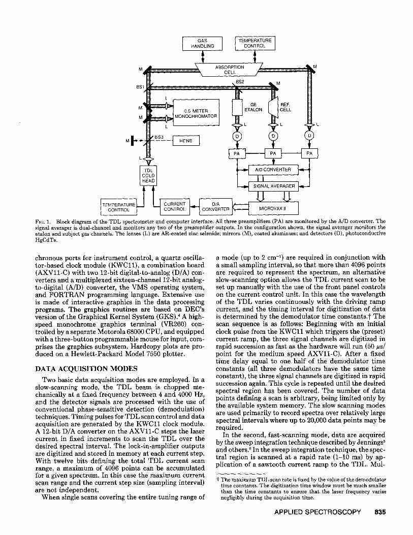
Figure 1 shows a block diagram of the TDL spectrom- eter and computer interface. A commercial (Spectra- Physics/Laser Analytics) diode laser cold head, a helium refrigeration unit, and controlling electronics and tern- perature stabilization units constitute the laser source assembly. The selected output beam from one of four TDLs is focused onto the input slit of a 1/2-m Ebert- type monochromator (Jarrell-Ash) used for mode selec- tion, if necessary. After passing through the monochro- mator, the TDL beam is collimated in a beam diameter of about 5 mm and split into three separate beams, as
Received 28 December 1988.
illustrated in Fig. 1. The peUicle-type beamsplitters (BS1, BS2) are constructed of polyethylene, 2 in. in diameter and 5 #m thick, and partially gold-coated to reflect ap- proximately 30% for BS1 and 60% for BS2. Pellicle beamsplitters were chosen to avoid optical interference fringes in the spectra resulting from reflections off of the two beamsplitter surfaces.* The three beams are directed along the signal paths shown in Fig. 1 and are focused onto cooled HgCdTe detectors equipped with commer- cial preamplifiers (Infrared Associates).
The etalon used for relative wavenumber calibration and general TDL beam diagnostics is a 7.62-cm solid Ge etalon with a 1-in. clear aperture (Spectra-Physics). An oven with active temperature stabilization was con- structed to maintain the etalon at a temperature a few degrees above the ambient laboratory temperature. The measured temperature stability of the etalon, monitored with thermistors (Omega #44031) attached to the outer etalon surface, is +0.02°C. Although the exact wave- length at which a transmission peak of the Ge etalon occurs is strongly dependent on the etalon temperature, interpolation on the observed fringe pattern to define a relative wavenumber scale relies only upon the relative spacing of the fringe peaks. With the use of the data of Edwin et al. 2 and Reddy et al., 3 the change in fringe spacing with temperature for a 7.62-cm Ge etalon is - 1.7 × 10 _6 cm-1/°C. Thus, variations in the etalon temper- ature of _+0.02°C result in corresponding variations in the etalon fringe spacing of only +_3.4 x 10 -8 cm -1 (0.001 MHz). This level of temperature stability is sufficient for interpolation over a 2-cm -I range (125 fringes for a 7.62- cm Ge etalon), with a maximum error in the interpolated position of a spectral line of +_4 × 10 -G cm -1 due to fluctuations in the fringe spacing alone. Much larger errors can arise from misalignment of the etalon in the optical path since the fringe spacing, or free-spectral-range (FSR), varies inversely with the optical path through the etalon2 Reduction of the clear aperture can minimize alignment errors, but it is important to verify the etalon FSR whenever the optical alignment is adjusted, if high accuracy in the wavenumber scale is required. A sub- routine automatically calculates the etalon (FSR) when- ever two or more reference lines occur in a recorded spectrum. The accuracy of the reference gas line posi- tions therefore determines the ultimate accuracy of the value used for the etalon FSR.
The Microvax II based computer system (DEC VAX- lab/RT) is equipped with 230 Mbytes of hard disk storage space, 5 Mbytes of main memory, tape backup units, a DHVl l serial interface with eight independent asyn-
* Fringes produced by the pellicle front and back surfaces have an FSR of several hundred cm -~ and are therefore not distinguishable in a TDL spectrum covering only 1-2 cm-L
834 Volume 43, Number 5, 1989 0003-7028/89/4305-083452.00/0 APPLIED SPECTROSCOPY © 1989 Society for Applied Spectroscopy
I GAS I TEMPERATUREI HANDLING CONTROL
BS
ABSORPTION CELL
. BS2
M , ETALON CELL MONOCHROMATOR }
M . L < L
M
A/D CONVERTER
SIGNALAVERAGER
TEMPERATURE ~ . ~ D / A CONTROL H L~ CURRENT CONTROL ~ R O V A X II ]
Fro. 1. Block diagram of the TDL spectrometer and computer interface. All three preamplifiers (PA) are monitored by the A/D converter. The signal averager is dual-channel and monitors any two of the preamplifier outputs. In the configuration shown, the signal averager monitors the etalon and subject gas channels. The lenses (L) are AR-coated zinc selenide; mirrors (M), coated aluminum; and detectors (D), photoconductive HgCdTe.
chronous ports for instrument control, a quartz oscilla- tor-based clock module (KWC11), a combination board (AXVll-C) with two 12-bit digital-to-analog (D/A) con- verters and a multiplexed sixteen-channel 12-bit analog- to-digital (A/D) converter, the VMS operating system, and FORTRAN programming language. Extensive use is made of interactive graphics in the data processing programs. The graphics routines are based on DEC's version of the Graphical Kernel System (GKS). 4 A high- speed monochrome graphics terminal (VR260) con- trolled by a separate Motorola 68000 CPU, and equipped with a three-button programmable mouse for input, com- prises the graphics subsystem. Hardcopy plots are pro- duced on a Hewlett-Packard Model 7550 plotter.
DATA ACQUISITION MODES
Two basic data acquisition modes are employed. In a slow-scanning mode, the TDL beam is chopped me- chanically at a fixed frequency between 4 and 4000 Hz, and the detector signals are processed with the use of conventional phase-sensitive detection (demodulation) techniques. Timing pulses for TDL scan control and data acquisition are generated by the K W C l l clock module. A 12-bit D/A converter on the AXVll -C steps the laser current in fixed increments to scan the TDL over the desired spectral interval. The lock-in-amplifier outputs are digitized and stored in memory at each current step. With twelve bits defining the total TDL current scan range, a maximum of 4096 points can be accumulated for a given spectrum. In this case the maximum current scan range and the current step size (sampling interval) are not independent.
When single scans covering the entire tuning range of
a mode (up to 2 c m -1) a r e required in conjunction with a small sampling interval, so that more than 4096 points are required to represent the spectrum, an alternative slow-scanning option allows the TDL current scan to be set up manually with the use of the front panel controls on the current control unit. In this case the wavelength of the TDL varies continuously with the driving ramp current, and the timing interval for digitization of data is determined by the demodulator time constants.t The scan sequence is as follows: Beginning with an initial clock pulse from the K W C l l which triggers the (preset) current ramp, the three signal channels are digitized in rapid succession as fast as the hardware will run (50 us/ point for the medium speed AXVll-C). After a fixed time delay equal to one half of the demodulator time constants (all three demodulators have the same time constant), the three signal channels are digitized in rapid succession again. This cycle is repeated until the desired spectral region has been covered. The number of data points defining a scan is arbitrary, being limited only by the available system memory. The slow scanning modes are used primarily to record spectra over relatively large spectral intervals where up to 20,000 data points may be required.
In the second, fast-scanning mode, data are acquired by the sweep integration technique described by Jennings ~ and others. 6 In the sweep integration technique, the spec- tral region is scanned at a rapid rate (1-10 ms) by ap- plication of a sawtooth current ramp to the TDL. Mul-
~" The maximum TDL scan rate is fixed by the value of the demodulator time constants. The digitization time window must be much smaller than the time constants to ensure tha t the laser frequency varies negligibly during the acquisition time.
APPLIED SPECTROSCOPY 8:35

~_~ ACQUIRE~STORE THREE-CHANNEL
DATA/ J I
CHANNEL 2 I CHANNEL 1 [ CHANNEL 3 (ETALON) ~ (SUBJECT GAS) ~ (REFERENCE GAS)
LOCATE FRINGE ] NORMALIZE TO NORMALIZE J TO
MAXIMA BASELINE BASELINE
~"~- ETALON ~ ASSIGN ~1~ I FSR WAVENUMBER LOCATE
KNOWN? SCALE PEAKS
USE REFERENCE SPECTRUM TO
t LINEARIZE
WAVENUMBER SCALE
SUBROUTINE LIBRARY FOR SPECTRUM PROCESSING/
STORAG E/PLOTTING
DETERMINE ETALON FSR
I [ FITTING/ TDL L ~ DECONVOLUTION
LINEWlDTH [ - [ FOR TDL KNOWN? j I LINEWIDTH ], ,
Fro. 2. Spectrum analysis flow chart.
tiple scans are accumulated in a high-speed digital signal averager (Nicolet 370) and tlhen transferred to the com- puter for processing. The fast-scanning mode is used for acquiring data over narrower spectral intervals where optimum frequency stability and signal-to-noise ratios (SNR) are required, such as in line broadening and line "splitting" measurements. 7 Switching between the fast and slow scanning data acquisition modes is a simple matter of redirecting the outputs of the detector pream- plifiers, and running the appropriate control program.
DATA PROCESSING
Three separate channels are recorded simultaneously to obtain the information needed for quantitative anal- ysis of a TDL spectrum:
Channel 1: Spectrum of the subject gas Channel 2: Interference fringes of a stabilized etalon Channel 3: Spectrum of a reference gas at low pres-
sure.
The etalon fringe pattern defines a relative wavenumber scale, and is also used to linearize the wavenumber scale via a polynomial interpolation procedure. An absolute wavenumber scale is derived from the reference gas spec- trum, which is also used to determine the TDL linewidth and to confirm the etalon FSR. Simultaneous recording of the three channels ensures that the TDL tuning char- acteristics (including the effective TDL linewidth) are determined under conditions identical to those of the subject gas spectrum, and also that the reference gas line positions are not displaced in frequency due to slight offsets in the exact starting current that may occur when scans are recorded at different times. A flow chart illus- trating the steps in the spectrum analysis procedure is shown in Fig. 2.
Baseline normalization is accomplished through poly- nomial fitting when the spectral line density is low and
the 100% transmission level is easily identified, or from a scan of the evacuated cell ("empty cell" scan) when a continuum absorption level is present due to high gas pressures or spectral line congestion. DC drifts in the detector outputs are reduced to the 0.2% transmission level by using "downward looking" detectors with 20 ° field-of-view shields to avoid interference from the lab- oratory lighting and equipment, by ensuring careful op- tical alignment to minimize optical fringing, and by using a low-noise precision voltage source (HP 6114A) to bias the detectors and preamplifiers.
Approximate spectral line positions and etalon fringe maxima are obtained with the use of first- and second- derivative locating procedures and, when necessary, from additional graphical input by the user. Final values are obtained from least-squares fitting procedures. A wave- number scale is assigned with the use of the known reference gas line positions and etalon FSR. Nonlinear- ities in the wavenumber scale are identified by irregu- larities in the number of data points separating the etalon fringe peaks. Finally, a library of subroutines is available for general spectrum manipulation and plotting, for least- squares fitting of direct transmission and harmonic absorption spectra, and deconvolution routines for de- termination of the TDL line shape function) and for removal of instrumental broadening. 9
EXAMPLES
Figure 3 shows a low-pressure spectrum of pure HN03 together with the reference gas spectrum (CH4), an etalon fringe pattern, and a spectrum of the evacuated absorp- tion cell used for baseline normalization of the HN03 spectrum. An atmospheric H20 line is also seen near the center of the scan. The curvature in the baselines is caused by the convolution of the TDL output power profile with the monochromator response function. The reference CH4 spectrum is normalized with the use of a
836 Volume 43, Number 5, 1989

4.50000 5.00000 ~
3.37500
CH 3: REF CH~
H20 ]
EMPTY CELL
/
1.75000 i
._J 0
< ~ 0 ~25000- CH 2: ETALON a " "
._J
• 1. 50000 l 1581 3121 4680 6240 7800
POINT NUMBER FIG. 3. Raw data recorded with the three-channel spectrometer. Scans, except the empty cell scan, are offset vertically for clarity. The broad absorption line present in all three channels is an atmospheric water line. HNO3 pressure, 0.032 Torr; temperature, 295 K; optical path- length, 96.5 cm.
polynomial baseline fit since the 100% transmission level is evident. For polynomial baseline fits, the user selects the regions of the baseline to be fit, using a mouse and crosshair locator. If the curvature of the baseline is se- vere, the baseline is broken down into smaller regions that are fitted separately and then connected smoothly at the endpoints to ensure a good overall fit.
After approximate location of tl~e reference line po- sitions and etalon fringe peaks using first- and second- derivative locating procedures, a centroid calculation is carried out to locate the exact peak centers. Figure 4 shows a portion of the normalized reference spectrum and the appearance of the graphics display after location of the etalon fringe maxima and reference line positions. The etalon FSR is calculated from the CH4 line positions and the fractional number of fringe peaks between the lines, and is labelled on the plot. The minimum and maximum step separation of the fringe peaks is also de- termined in order to give an indication of the TDL tuning linearity. For this example the step separation varied from a minimum of 146 steps near the right-hand side of the spectrum to a maximum of 157 steps near the middle. The difference of 11 steps between the maximum and minumum step separation corresponds to about 33 MHz, or 7 % of the etalon FSR, indicating that tuning nonlinearities across the scan are not severe. An absolute wavenumber value is now assigned to each point in the spectrum, with the assumption that the TDL tunes lin- early over one etalon FSR (0.0163 cm-I). Confocal air- spaced etalons can produce more closely spaced fringes and therefore provide a better map of the TDL tuning behavior, which increases the accuracy of the wavenum- ber assignment} °
Irregularities in the point spacing between the etalon fringe peaks indicate nonlinearities in the TDL tuning rate, provided that the etalon temperature and TDL temperature are constant during the course of the scan. Sinusoidal oscillations in the fringe spacing usually in- dicate oscillations in the etalon or TDL temperature con- trol circuits. A linear wavenumber scale is required if the
3 .42500-
LLJ 0 < I'-- _ ~ 2 . 3 8 0 0 0
0 >
.< H _ ~ 1.27550
0 .200000
r o
t5161 , 3112 i E 46180 , 52140 ' 7800
POINT NUMBER FIG. 4. Appearance of the graphics display after location of the etalon fringe maxima and reference spectrum line positions. Only a portion of the spectrum near the reference gas lines is shown. The reference spectrum was recorded with the use of about 10% of the laser power. The etalon FSR is calculated from the known CH, line positions. Im- proper location of peaks by the subroutine can be identified easily from the plot.
spectrum is to be subjected to least-squares fitting or deconvolution procedures, and it is necessary to inter- polate on the observed spectrum in order to obtain a linear scale. The linear wavenumber scale is defined by
v~ = ~1 + (i - 1)A~; i = 1, n (1)
where i runs over the number of points (n) in the spec- trum and
A ~ = ( v . - ~ l ) l ( n - 1) (2)
is the required point spacing for the linear scale. Vl and v, represent the wavenumbers of the left and right bound- ary points of the spectrum, generally taken to be the leftmost and rightmost fringe peaks since their separa- tion is accurately known. Interpolation is carried out with the use of a cubic interpolation routine 11 to arrive at the final wavenumber scale. The interpolation procedure is accurate when the deviations from linearity are small, and when the sampling interval is a small fraction of the molecular linewidth. It is worth noting that, in compar- ison to those fabricated only a few years ago, newer TDLs show marked improvement in tuning linearity.
The effective instrumental width is obtained from a deconvolution procedure, s and also from least-squares fitting of observed Doppler-limited absorption lines for comparison to the theoretical Doppler half-width. Al- though instrumental broadening can sometimes be ig- nored in TDL spectroscopy (for example when gas sam- ples at moderate to high pressures are being studied, or when the TDL is mounted in a liquid cryogen dewar and operated with an ultra-stable current source), mechan- ical closed-cycle coolers and commercial current sources powered from the ac line voltage can both act to increase the TDL linewidth to significant levels. This is especially true for the newer-geometry TDLs, which often tune at rates greater than 1000 MHz/mA. Current source noise levels of 50/~A peak-to-peak can therefore translate to effective TDL linewidths of several tens of MHz. Thus,
APPLIED SPECTROSCOPY 837
0.757500
Z CD t -4
c0 (j-Je,5osoco
F-4
O9 Z
[-~0,252500
0,000000
~.0~000 -
[ I
I I
a) Synthetlc HN05
i I
0.757500
Z O H 03 (J~O.5O5OOO
Z O3 Z
E0.252500
b--
o.oooooo
~337.571o
1 1 b) Expepimental HN03
I i I r l ~ [ 1337.7410 1337.9110 1338.0809 1338.2510 1338.4209
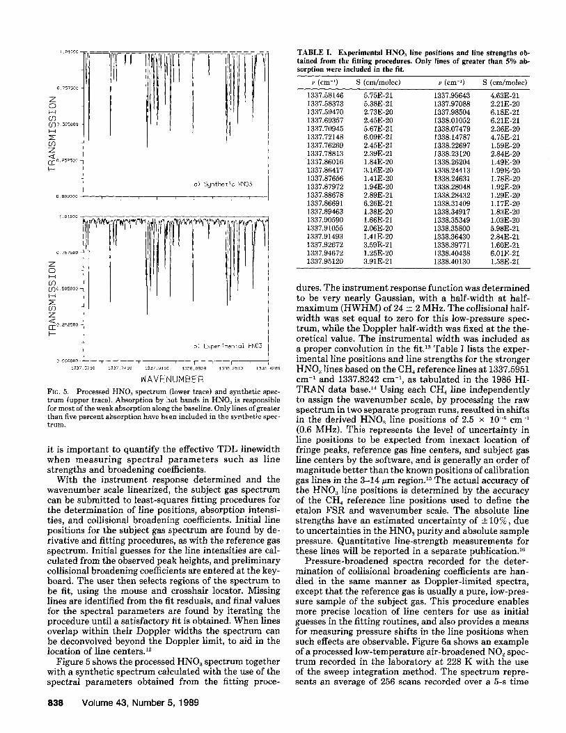
WAVENUMBER FIG. 5. Processed HN03 spectrum (lower trace) and synthetic spec- t rum (upper trace). Absorption by ]hot bands in HN03 is responsible for most of the weak absorption along the baseline. Only lines of greater than five percent absorption have been included in the synthetic spec- trum.
it is important to quantify the effective TDL linewidth when measuring spectral parameters such as line strengths and broadening coefficients.
With the instrument response determined and the wavenumber scale linearized, the subject gas spectrum can be submitted to least-squares fitting procedures for the determination of line positions, absorption intensi- ties, and collisional broadening coefficients. Initial line positions for the subject gas spectrum are found by de- rivative and fitting procedures, as with the reference gas spectrum. Initial guesses for the line intensities are cal- culated from the observed peak heights, and preliminary collisional broadening coefficients are entered at the key- board. The user then selects regions of the spectrum to be fit, using the mouse and crosshair locator. Missing lines are identified from the fit. resduals, and final values for the spectral parameters are found by iterating the procedure until a satisfactory fit is obtained. When lines overlap within their Doppler widths the spectrum can be deconvolved beyond the Doppler limit, to aid in the location of line centers. ~
Figure 5 shows the processed HNO~ spectrum together with a synthetic spectrum calculated with the use of the spectral parameters obtained from the fitting proce-
TABLE I. Experimental HNO3 line positions and line strengths ob- tained from the fitting procedures. Only lines of greater than 5% ab- sorption were included in the fit.
v (cm-9 S (cm/molec) ~ (cm 1) S (cm/molec)
1337.58146 5.75E-21 1337.95643 4.63E-21 1337.58373 5.38E-21 1337.97088 2.21E-20 1337.59470 2.73E-20 1337.98504 6.18E-21 1337.69357 2.45E-20 1338.01052 6.21E-21 1337.70945 5.67E-21 1338.07479 2.36E-20 1337.72148 6.09E-21 1338.14787 4.75E-21 1337.76269 2.45E-21 1338.22697 1.59E-20 1337.78813 2.39E-21 1338.23120 2.84E-20
1337.86016 1.84E-20 1338.26204 1.49E-20 1337.86417 3.16E-20 1338.24413 1.99E-20 1337.87656 1.41E-20 1338.24631 1.78E-20 1337.87972 1.94E-20 1338.28048 1.92E-20 1337.88678 2.89E-21 1338.28432 1.29E-20 1337.86691 6.26E-21 1338.31409 1.17E-20 1337.89463 1.38E-20 1338.34917 1.83E-20 1337.90590 1.66E-21 1338.35349 1.03E-20 1337.91055 2.06E-20 1338.35800 5.98E-21 1337.91493 1.41E-20 1338.36430 2.84E-21 1337.92672 3.59E-21 1338.39771 1.60E-21 1337.94672 1.25E-20 1338.40438 6.01E-21 1337.95120 3.91E-21 1338.40130 1.58E-21
dures. The instrument response function was determined to be very nearly Gaussian, with a half-width at half- maximum (HWHM) of 24 __+ 2 MHz. The collisional half- width was set equal to zero for this low-pressure spec- trum, while the Doppler half-width was fixed at the the- oretical value. The instrumental width was included as a proper convolution in the fit. 13 Table I lists the exper- imental line positions and line strengths for the stronger HNO3 lines based on the CH4 reference lines at 1337.5951 cm -~ and 1337.8242 cm -~, as tabulated in the 1986 HI- TRAN data base. 14 Using each CH4 line independently to assign the wavenumber scale, by processing the raw spectrum in two separate program runs, resulted in shifts in the derived HN03 line positions of 2.5 × 10 -5 cm -~ (0.6 MHz). This represents the level of uncertainty in line positions to be expected from inexact location of fringe peaks, reference gas line centers, and subject gas line centers by the software, and is generally an order of magnitude better than the known positions of calibration gas lines in the 3-14 ~m region. 15 The actual accuracy of the HN03 line positions is determined by the accuracy of the CH4 reference line positions used to define the etalon FSR and wavenumber scale. The absolute line strengths have an estimated uncertainty of + 10%, due to uncertainties in the HN03 purity and absolute sample pressure. Quantitative line-strength measurements for these lines will be reported in a separate publication. '6
Pressure-broadened spectra recorded for the deter- mination of collisional broadening coefficients are han- dled in the same manner as Doppler-limited spectra, except that the reference gas is usually a pure, low-pres- sure sample of the subject gas. This procedure enables more precise location of line centers for use as initial guesses in the fitting routines, and also provides a means for measuring pressure shifts in the line positions when such effects are observable. Figure 6a shows an example of a processed low-temperature air-broadened NO2 spec- trum recorded in the laboratory at 228 K with the use of the sweep integration method. The spectrum repre- sents an average of 256 scans recorded over a 5-s time
838 Volume 43, Number 5, 1989

C.O0000
0.937500
z o H r.,9 ~j ' ]0.975000- I--.I z o3 z --~o.g12500-
}--
01750000
O.OOi50O
P(o i r ) : 40.16 Tort
T: 227.7 K
L: 53.3 ~m
be: 0.091 cm-i/otm
i J St--'
l i
N02 ( b )
ELI T: ~3~.0 K
L: z~O000 c,m
be: 0.089 c..m-I/otm l--qO .O00150
__l --. £I_ 5- <f
EL.-" ooo59s
CU
-,001200
WAVENUMBER
FIG. 6. Examples of leastisquares fits to low-temperature transmission (a) and second harmonic (b) pressure-broadened NO2 spectra. The fitted spectra are plotted on top of the experimental spectra (unfor- tunately in the same color here), with fit residuals (observed-calculated) plotted below the experimental spectra and on the same vertical scale; bc is the fitted collisional broadening coefficient in units of cm-~/atm.
period, and contains six spectral lines occurring in closely spaced pairs, as indicated in the figure. A least-squares fit to a spectrum of Voigt lines yields line center posi- tions, line strengths, and collisional broadening coeffi- cients for the individual spectral lines. Up to ten lines may be fitted simultaneously. An average pressure- broadening coefficient of 0.091 cm -z at 228 K is derived from a fit to the spectrum shown. Figure 6b shows a second harmonic spectrum of these same NO2 features obtained by placing a sinusoidal modulat ion on the T D L current at f requency f (2 kHz), and monitoring the de- tector signal component at 2f (4 kHz). This spectrum
was recorded in s i t u in the stratosphere near 31 km alti tude with the use of a balloon-borne diode laser spec- trometer. 17 The optical pathlength, defined by the round- trip distance between the ins t rument gondola and a low- ered retroflector, was 400 m. Separate subroutines allow fitting of harmonic T D L spectra for the extraction of volume mixing ratios and air-broadening coefficients for low gas concentrat ion samples requiring the sensitivity of harmonic detection techniques, is The spectrum in Fig. 6b corresponds to an N02 volume mixing ratio of 10.5 ppbv at a total pressure of 8.72 Torr, and required 4 min of data collection. Absorptions as low as 10 -~ may be detected with the use of harmonic detection techniquesJ s Results from the balloon flight will be reported else- where.
The program library also includes routines for gen- erating and plott ing synthet ic spectra using spectral data contained in the 1986 AFGL H I T R A N data base. 14
ACKNOWLEDGMENT
The research described in this paper was carried out by the Jet Propulsion Laboratory, California Institute of Technology, under a contract with the National Aeronautics and Space Administration.
1. Spectra-Physics/Laser Analytics reprint list (1986). 2. E. P. Edwin, M. T. Dudermel, and M. Lamare, J. Opt. Soc. Am.
52, 420 (1962). 3. S. P. Reddy, W. Ivancic, V. Malathy Devi, A. Baldacci, K. N. Rao,
A. W. Mantz, and R. S. Eng, Appl. Opt. 18, 1350 (1979). 4. See, for example, F. R. A. Hopgood, D. A. Duce, J. R. Gallop, and
D. C. Sutcliffe, Introduction to the Graphical Kernel System (GKS) (Academic Press, New York, 1983).
5. D. E. Jennings, Appl. Opt. 19, 2695 (1980). 6. J.R. Podolske, M. Loewenstein, and P. Varanasi, J. Mol. Spectrosc.
107, 241 (1984). 7. R. L. Sams and A. Fried, J. Mol. Spectrosc. 125, 129 (1987). 8. R. D. May, JQSRT 39, 247 (1988). 9. R. D. May, L. T. Molina, and C. R. Webster, J. Phys. Chem. 92,
4667 (1988). 10. D. E. Jennings, Appl. Opt. 23, 1299 (1984). 11. W. H. Press, B. P. Flannery, S. A. Teukolsky, and W. T. Vetterling,
Numerical Recipes (Cambridge University Press, Cambridge, 1986), Chap. 3, p. 82.
12. R. D. May and C. R. Webster, JQSRT 38, 5 (1987). 13. Deconvolution: with Applications in Spectroscopy, P. A. Jansson,
Ed. (Academic Press, New York, 1984). 14. L. S. Rothman, R. R. Gamache, A. Goldman, L. R. Brown, R. A.
Toth, H. M. Pickett, R. L. Poynter, J.-M. Flaud, C. Camy-Peyret, A. Barbe, N. Husson, C. P. Rinsland, and M. A. H. Smith, Appl. Opt. 26, 4058 (1987).
15. G. Guelachvili and K. Narahari Rao, Handbook of Infrared Stan- dards (Academic Press, New York, 1986).
16. R. D. May, paper to be submitted to J. Mol. Spectros. 17. C. R. Webster and R. D. May, J. Geophys. Res. 92, 11931 (1987). 18. C. R. Webster, R. T. Menzies, and E. D. Hinkley, in Laser Remote
Chemical Analysis, R. M. Measures, Ed. (Wiley and Sons, New York, 1988), Chap. 3, p. 163.
APPLIED SPECTROSCOPY 839