Embed Size (px)
Citation preview
Computer Graphics !
LECTURE 4 HIERARCHICAL MODELING
INTRODUCTION TO 3D CONCEPTS
Doç. Dr. Mehmet Gokturk Gebze Institute of Technology
!
© M. Gokturk 2
Structure Concept!● In many graphics applications, it is necessary to be able to modify
parts of the whole model/picture. ● Therefore hierachical structures are used. ● All labeled set of output primitives are called structure: glBegin(GL_POLYGON);
glVertex3f (0.25, 0.25, 0.0); glVertex3f (0.75, 0.25, 0.0); glVertex3f (0.75, 0.75, 0.0); glVertex3f (0.25, 0.75, 0.0); glEnd(); !
© M. Gokturk 3
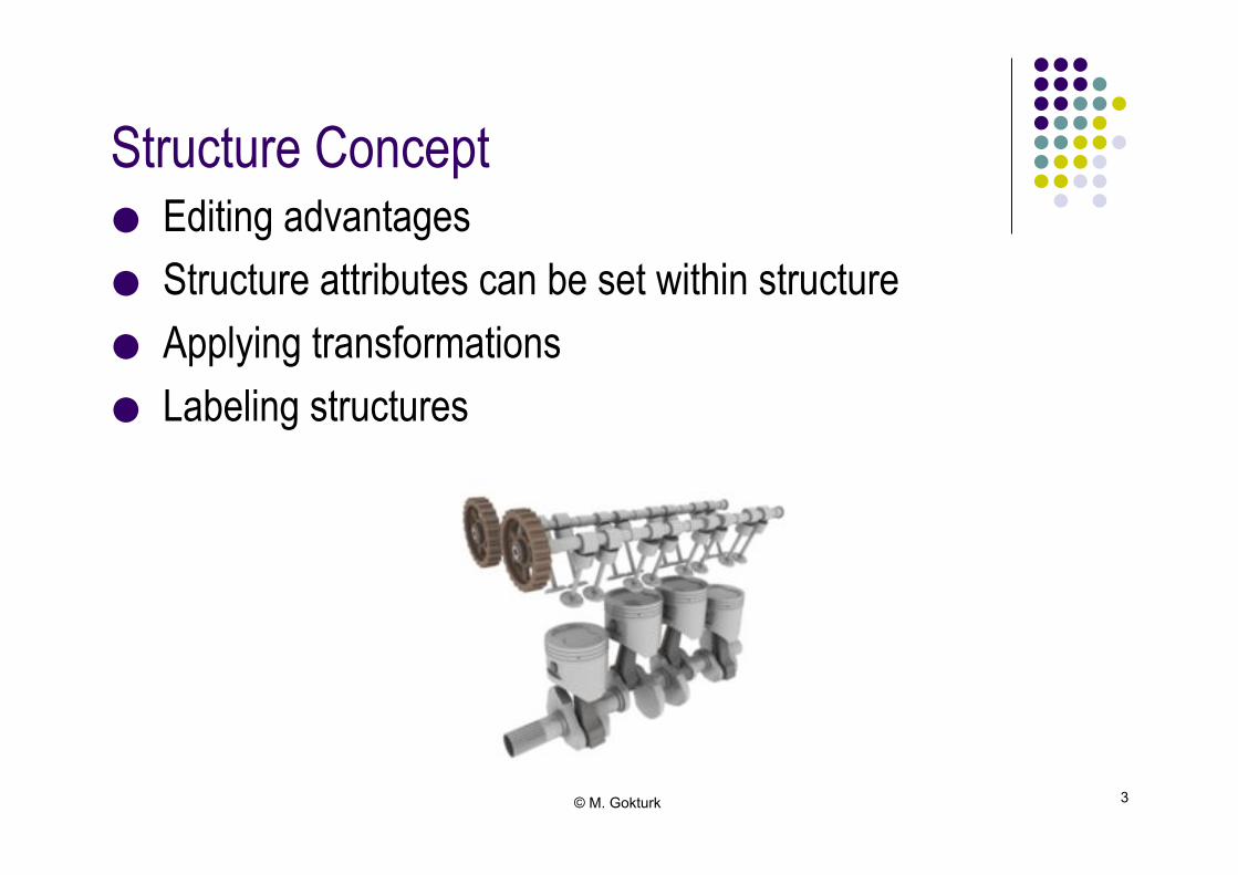
Structure Concept!● Editing advantages ● Structure attributes can be set within structure ● Applying transformations ● Labeling structures!

© M. Gokturk 4
Example (openGL)!/* Draw the field lines */! r1 = 12;! r2 = 16;! for (j=0;j<360;j+=20) {! glPushMatrix();! glRotatef((double)j,0.0,1.0,0.0);! glBegin(GL_LINE_STRIP);! glColor3f(grey.r,grey.g,grey.b);! for (i=-140;i<140;i++) {! x = r1 + r1 * cos(i*DTOR);! y = r2 * sin(i*DTOR);! z = 0;! glVertex3f(x,y,z); ! } ! glEnd();! glPopMatrix(); ! }!
© M. Gokturk 5
Basic Modeling Concepts!
● Engineering ● Architecture ● Design ● Economic and Social
● The creation and manipulation of a system representation is called modeling
● Any single representation is called a model of the system (can be descriptive or graphical)
● Graphical models are often called as geometric models!

© M. Gokturk 6
Symbols and Instances!
● Component parts of the system are displayed as geometric structures, called symbols
● Each occurrence of a symbol within a model is called an instance of that symbol!
Model of a logic circuit
© M. Gokturk 7
Symbol Hieracrchies!
● Many models can be organized as a hierarchy of symbols ● The basic “building blocks” for the model are defined as
simple geometric shapes appropriate to the type of model under consideration
● The basic symols can be used to form composite objects, called modules
● They can be grouped to form higher-level modules!

© M. Gokturk 8
Symbol Hierarchies - Example!
Logic circuit
AND NOR OR AND
One level hierarchical description of a circuit formed with logic gates

© M. Gokturk 9
Symbol Hierarchies – Example 2!
...
... TABLE CHAIR Cabinet TABLE Shelves Cabinet Desk
workarea2 workarea1
FACILITY
A two-level hierarchical description of a facility layout
© M. Gokturk 10
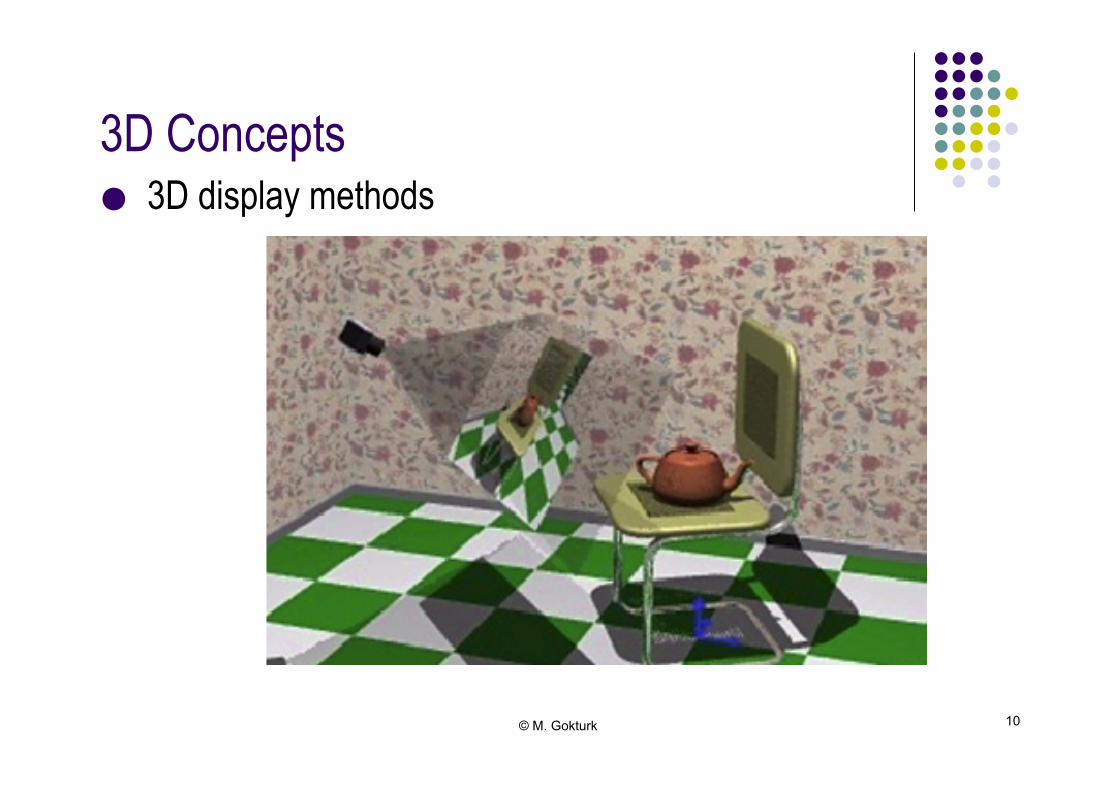
3D Concepts!
● 3D display methods!
© M. Gokturk 11
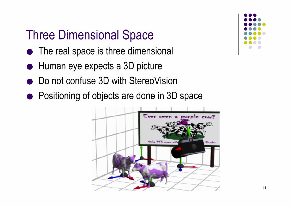
Three Dimensional Space!
● The real space is three dimensional ● Human eye expects a 3D picture ● Do not confuse 3D with StereoVision ● Positioning of objects are done in 3D space!
© M. Gokturk 12
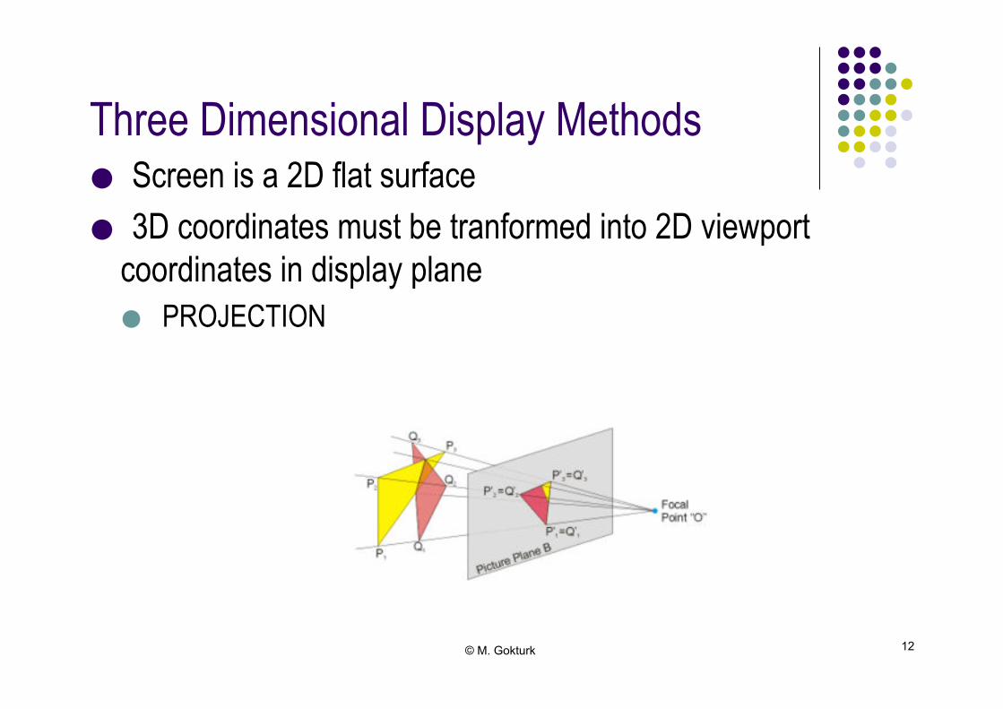
Three Dimensional Display Methods!
● Screen is a 2D flat surface ● 3D coordinates must be tranformed into 2D viewport
coordinates in display plane ● PROJECTION!
© M. Gokturk 13
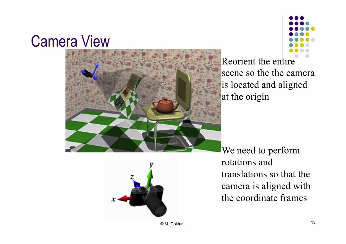
Camera View!
Reorient the entire scene so the the camera is located and aligned at the origin
We need to perform rotations and translations so that the camera is aligned with the coordinate frames
© M. Gokturk 14
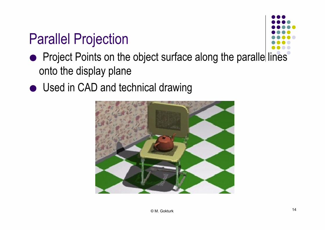
Parallel Projection!
● Project Points on the object surface along the paralle lines onto the display plane
● Used in CAD and technical drawing!

© M. Gokturk 15
Mapping to Pixel Coordinates!
This process is often called the viewport transformation
© M. Gokturk 16
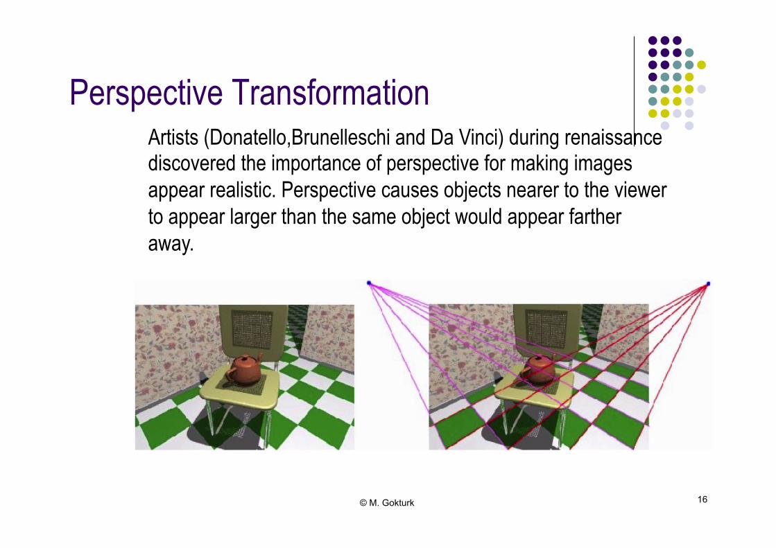
Perspective Transformation!
Artists (Donatello,Brunelleschi and Da Vinci) during renaissance discovered the importance of perspective for making images appear realistic. Perspective causes objects nearer to the viewer to appear larger than the same object would appear farther away.
© M. Gokturk 17
Perspective Projection!
● Project points to display plane along converging paths ● Objects farther from the viewing poisition appear smaller ● Parallel lines are projected as non-parallel lines, converging
at some distant point ● Vanishing point
● Perspective projection is more realistic ● Human eye perceives the world with perspective projection!

© M. Gokturk 18
Depth Cueing!
● Distant objects are dimmed slightly ● Effect of haze, air and scattering ● Color can be changed slightly as well!
© M. Gokturk 19
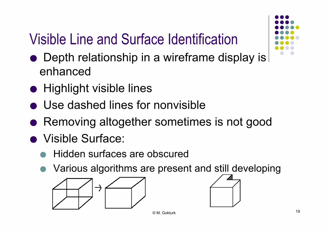
Visible Line and Surface Identification!
● Depth relationship in a wireframe display is enhanced
● Highlight visible lines ● Use dashed lines for nonvisible ● Removing altogether sometimes is not good ● Visible Surface: ● Hidden surfaces are obscured ● Various algorithms are present and still developing!

© M. Gokturk 20
Surface Rendering!
● Setting surface intensity of objects according to the lighting condition ● Polygon rendering and Surface rendering (OpenGL) using scan
line methods ● Ray tracing pixel by pixel ● Radiosity techniques by volume!
© M. Gokturk 21
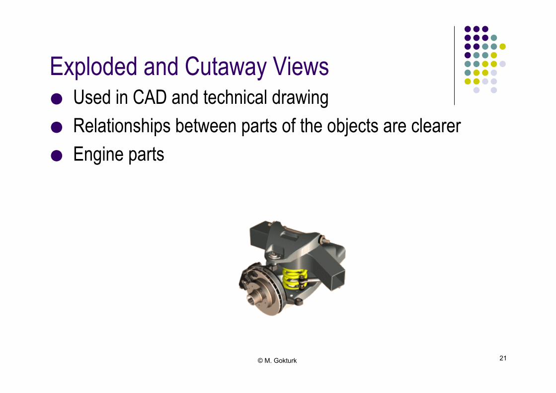
Exploded and Cutaway Views!
● Used in CAD and technical drawing ● Relationships between parts of the objects are clearer ● Engine parts!
© M. Gokturk 22
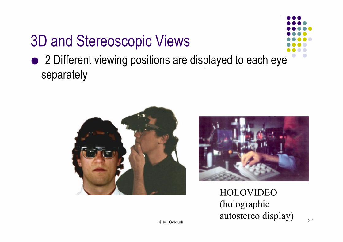
3D and Stereoscopic Views!
● 2 Different viewing positions are displayed to each eye separately!
HOLOVIDEO (holographic autostereo display)
© M. Gokturk 23
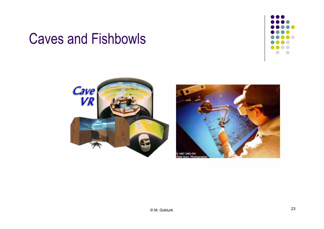
Caves and Fishbowls!
© M. Gokturk 24
3D Object Representations!
● Objects in 3D world must be modeled and recorded to the computer memory in order to be processed
● Representing complex objects is usually a challenge ● Performance considerations!
© M. Gokturk 25
Polygon Surfaces!
● Enclose object within the polygon surfaces ● Not a unique model for the object ● Simple and fast ● Lots of polygons ● Polygon Mesh ● Easy to display in wireframe during design stage!

© M. Gokturk 26
Polygon Tables!
● Vertex Table ● Edge Table ● Surface Table!
E1
E2 E4
E3
E5
E6
V1
V5 V3 V2
V4
VERTEX TABLE V1 x1,y1,z1 V2 x2,y2,z2 V3 x3,y3,z3 V4 x4,y4,z4 V5 x5,y5,z5
POLYGON-SURFACE TABLE
S1 E1,E2,E3 S2 E3,E4,E5,E6
EDGE TABLE E1 V1,V2 E2 V2,V3 E3 V3,V1 E4 V3,V4 E5 V4,V5 E6 V5,V1
© M. Gokturk 27
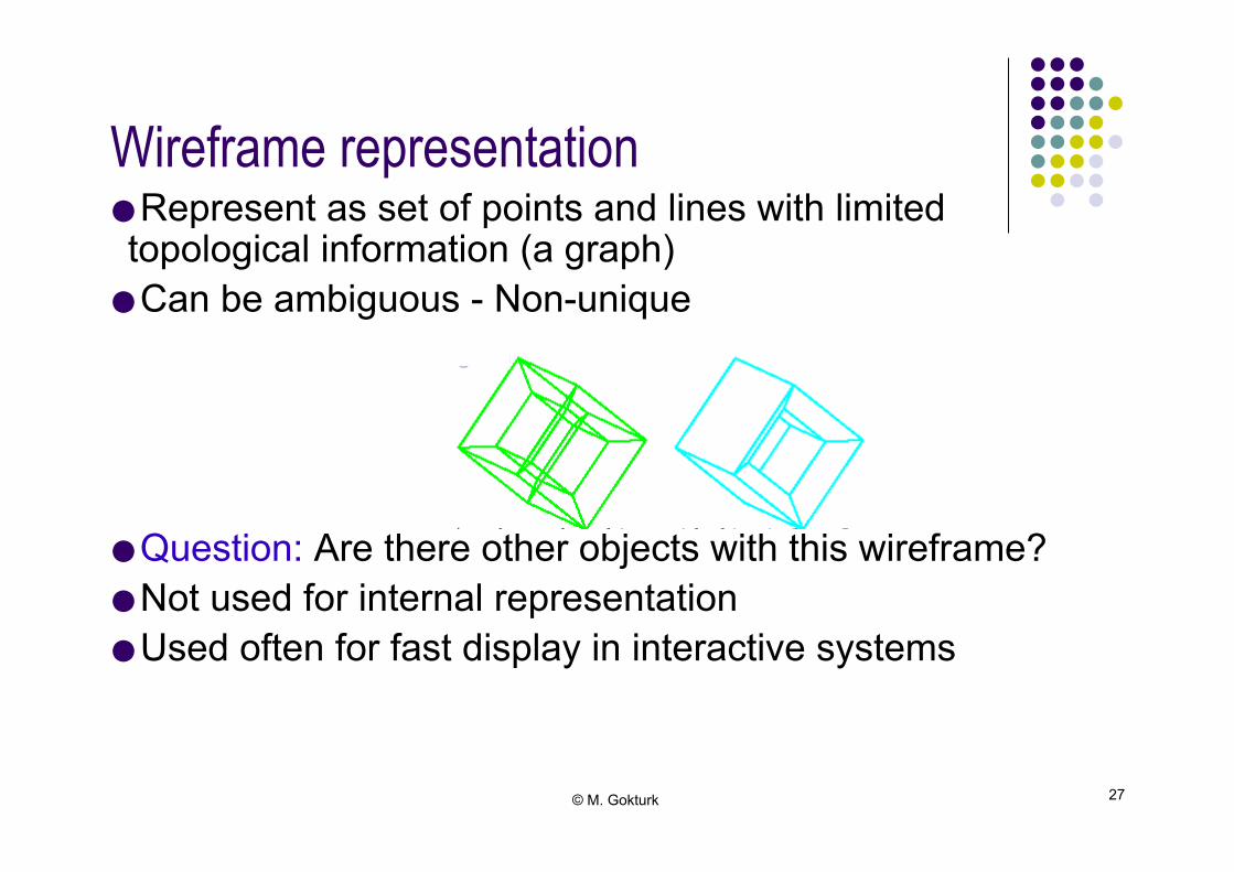
Wireframe representation!
● Represent as set of points and lines with limited topological information (a graph) ● Can be ambiguous - Non-unique ● Question: Are there other objects with this wireframe? ● Not used for internal representation ● Used often for fast display in interactive systems!

© M. Gokturk 28
Plane Equations!
● Ax+By+Cz+D=0 where x,y,z is any point on a plane ● Three noncollinear points can determine A,B,C,D ● Select (x1,y1,z1),(x2,y2,z2),(x3,y3,z3)!
© M. Gokturk 29
Plane Equations!
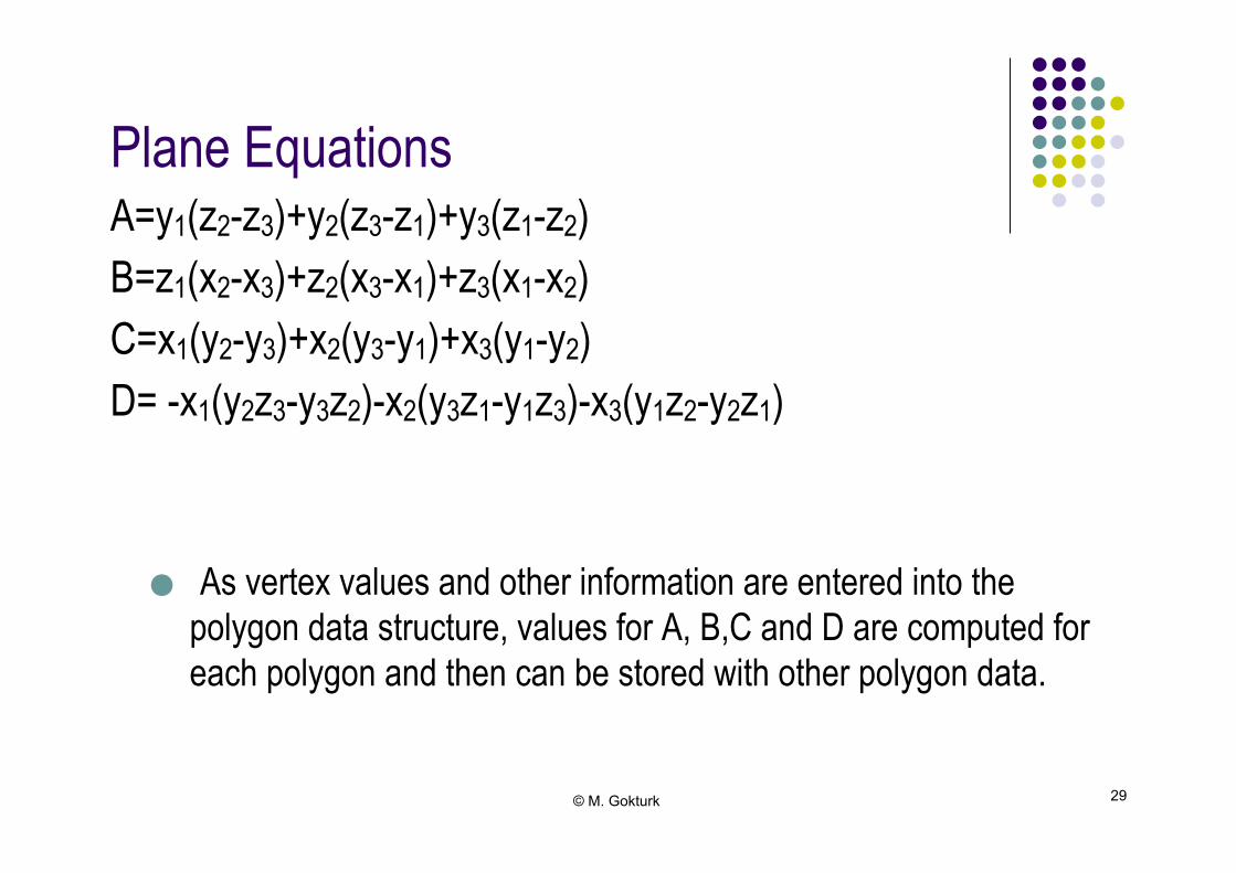
A=y1(z2-z3)+y2(z3-z1)+y3(z1-z2) B=z1(x2-x3)+z2(x3-x1)+z3(x1-x2) C=x1(y2-y3)+x2(y3-y1)+x3(y1-y2) D= -x1(y2z3-y3z2)-x2(y3z1-y1z3)-x3(y1z2-y2z1) ● As vertex values and other information are entered into the
polygon data structure, values for A, B,C and D are computed for each polygon and then can be stored with other polygon data.!

© M. Gokturk 30
Normal Vector!● N=(A,B,C)!
N
© M. Gokturk 31
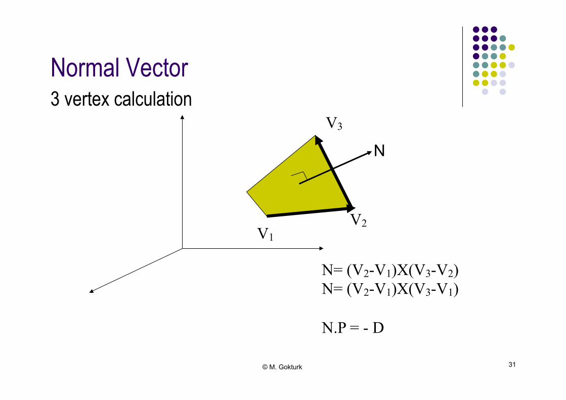
Normal Vector!3 vertex calculation!
N
V1 V2
V3
N= (V2-V1)X(V3-V2) N= (V2-V1)X(V3-V1) N.P = - D
© M. Gokturk 32
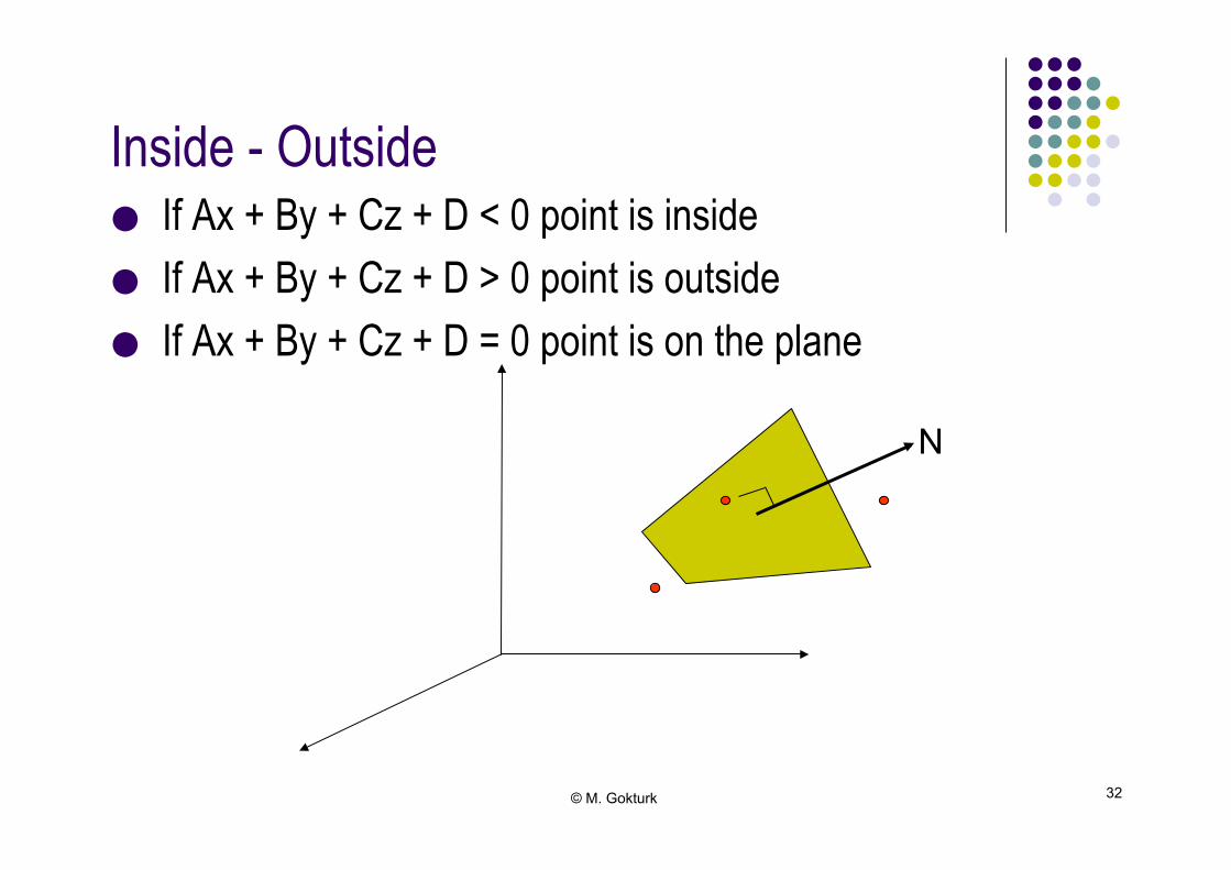
Inside - Outside!
● If Ax + By + Cz + D < 0 point is inside ● If Ax + By + Cz + D > 0 point is outside ● If Ax + By + Cz + D = 0 point is on the plane!
N
© M. Gokturk 33
Polygon Meshes!
● Construct the object from triangles or quadrilaterals by tiling ● Most models are constructed this way ● Easy to work with ● Easy to render ● Rates about 300 million triangles/sec available with
ordinary graphics cards for PC computers!

© M. Gokturk 34
Polygon Meshes -triangular meshes-!● Free form/Boolean disadvantages: complexity of description &
algorithms ● Representing a model as closed triangular mesh is EASY –
Operations & Description format very simple ● Base representation for scanned data ● Most popular web representation!

© M. Gokturk 35
Why triangular meshes?!
● Rasterizing triangles ● Interpolating parameters ● Post-triangle rendering ● Data structure ● 3 vertices ● Can approximate arbitrary shapes!

© M. Gokturk 36
Curved Lines and Surfaces!
● Quadric Surfaces ● Sphere ● Ellipsoid ● Torus
● Superquadrics (play with mode parameters) ● Superellipse ● Superellipsoid!
© M. Gokturk 37
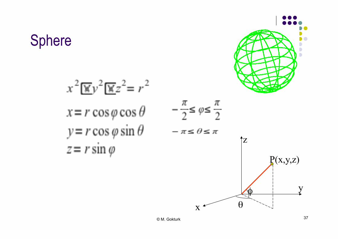
Sphere!
P(x,y,z)
x
y
z
φ θ
© M. Gokturk 38
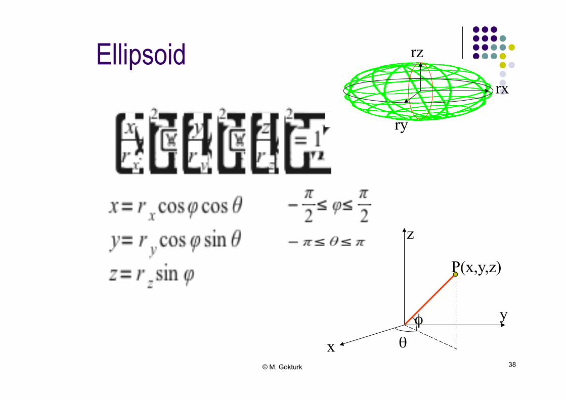
Ellipsoid
P(x,y,z)
x
y
z
φ θ
rx
ry
rz
© M. Gokturk 39
Blobby Objects!
● Blobbiness ● Molecular shapes ● Gravitational, proximity conditions ● Field conditions ● Gaussian density functions!
© M. Gokturk 40
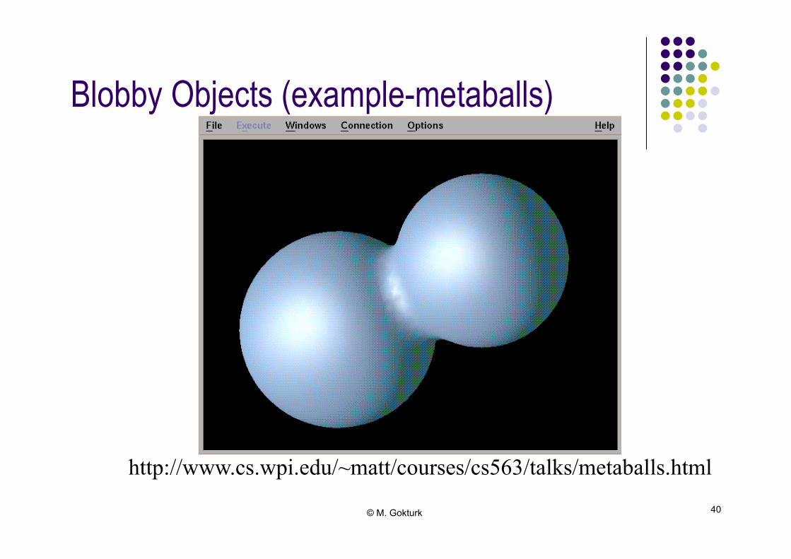
Blobby Objects (example-metaballs)!
http://www.cs.wpi.edu/~matt/courses/cs563/talks/metaballs.html
© M. Gokturk 41
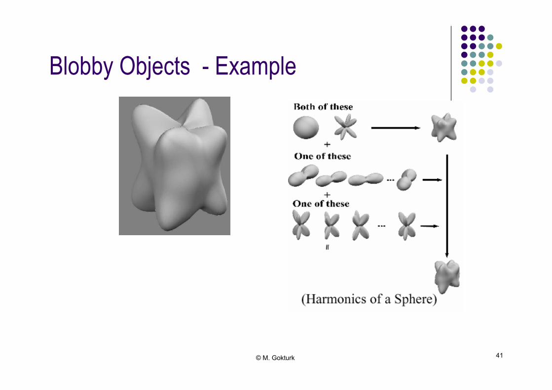
Blobby Objects - Example!
© M. Gokturk 42
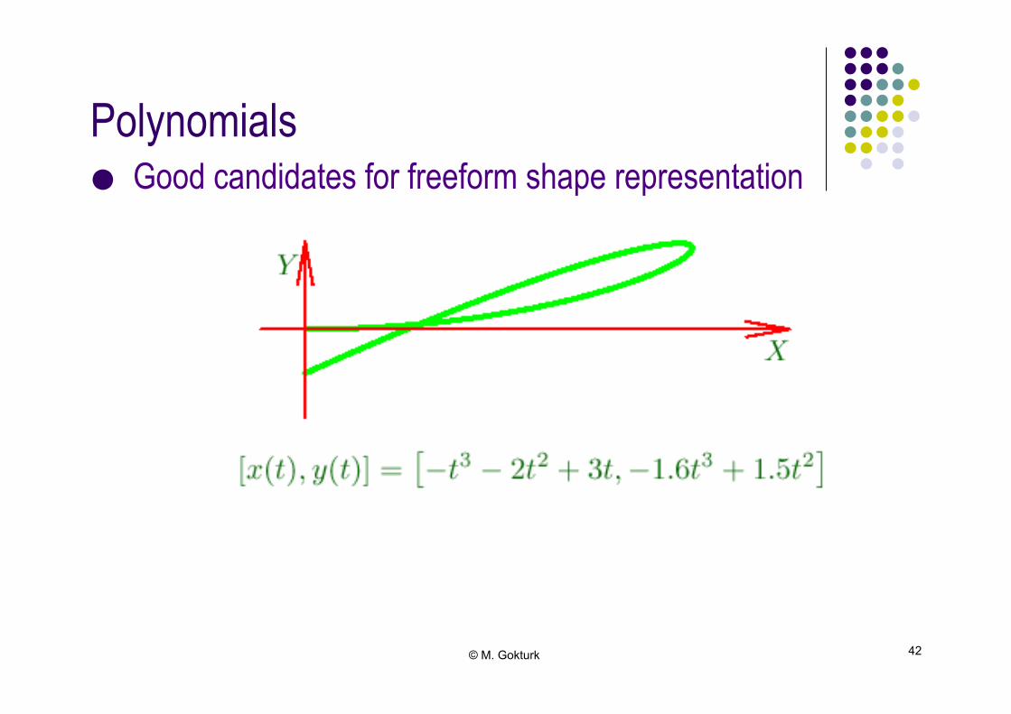
Polynomials!
● Good candidates for freeform shape representation!

© M. Gokturk 43
Splines!
● Original spline device used in technical drawing ● Spline surfaces ● Control points ● Interpolation (Bezier) ● Approximation (Cubic)!

© M. Gokturk 44
Splines: Interpolation!
● When polynomial sections are fitted so that the curve passes through each control point, the resulting curve is said to interpolate the set of control points.
● Interpolation curves are commonly used to digitize drawings or to specify animation paths!
© M. Gokturk 45
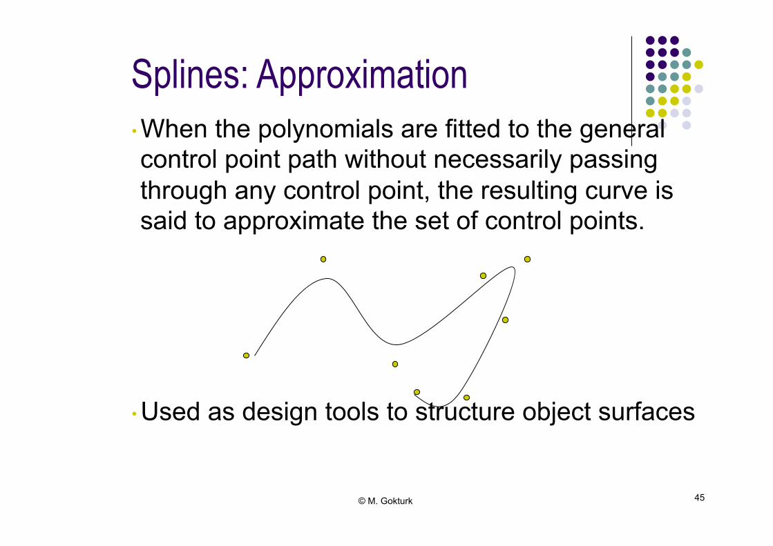
• When the polynomials are fitted to the general control point path without necessarily passing through any control point, the resulting curve is said to approximate the set of control points.
• Used as design tools to structure object surfaces
Splines: Approximation
© M. Gokturk 46
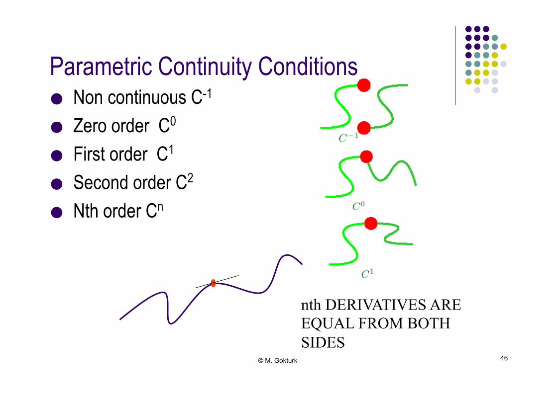
Parametric Continuity Conditions!
● Non continuous C-1
● Zero order C0
● First order C1
● Second order C2
● Nth order Cn!
nth DERIVATIVES ARE EQUAL FROM BOTH SIDES
© M. Gokturk 47
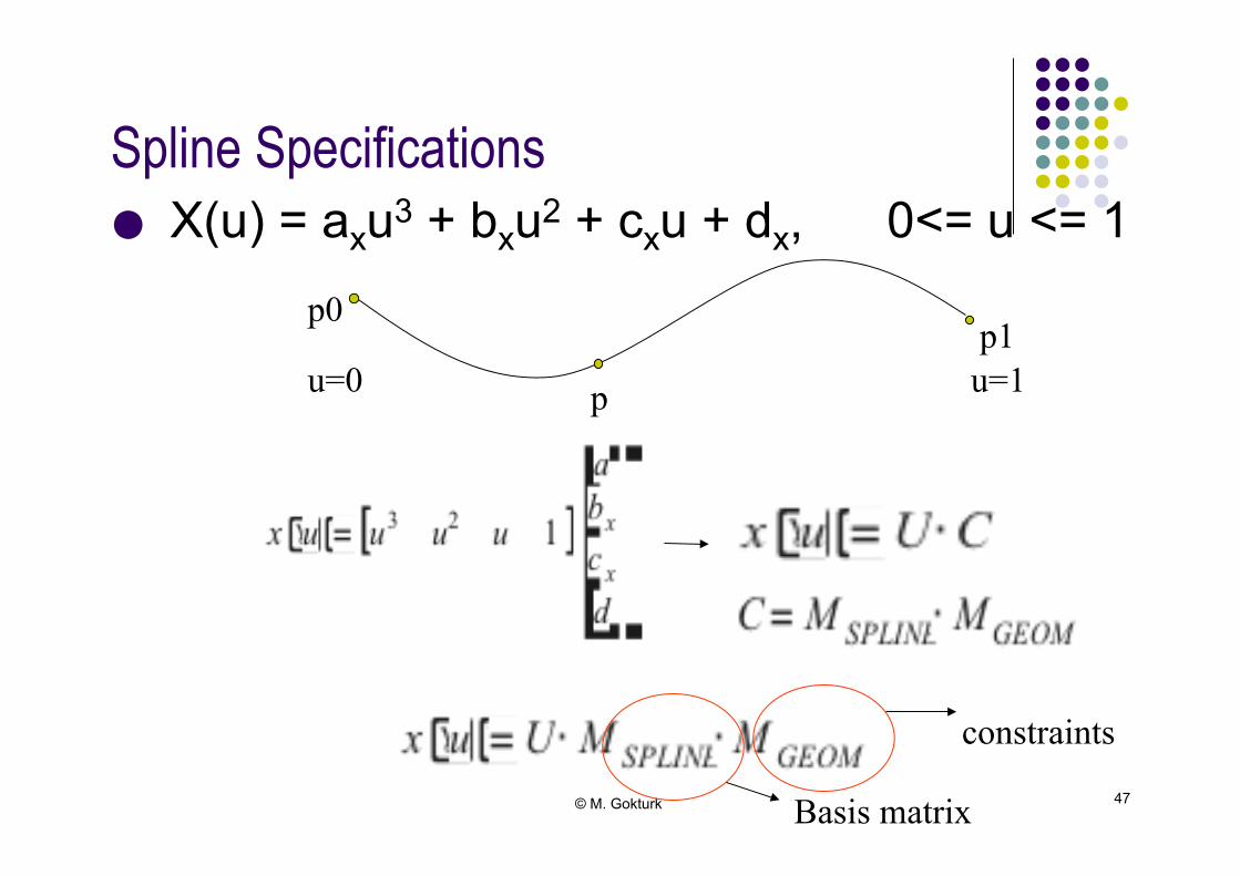
Spline Specifications!
● X(u) = axu3 + bxu2 + cxu + dx, 0<= u <= 1!
p0
p
p1 u=0 u=1
Basis matrix
constraints
© M. Gokturk 48
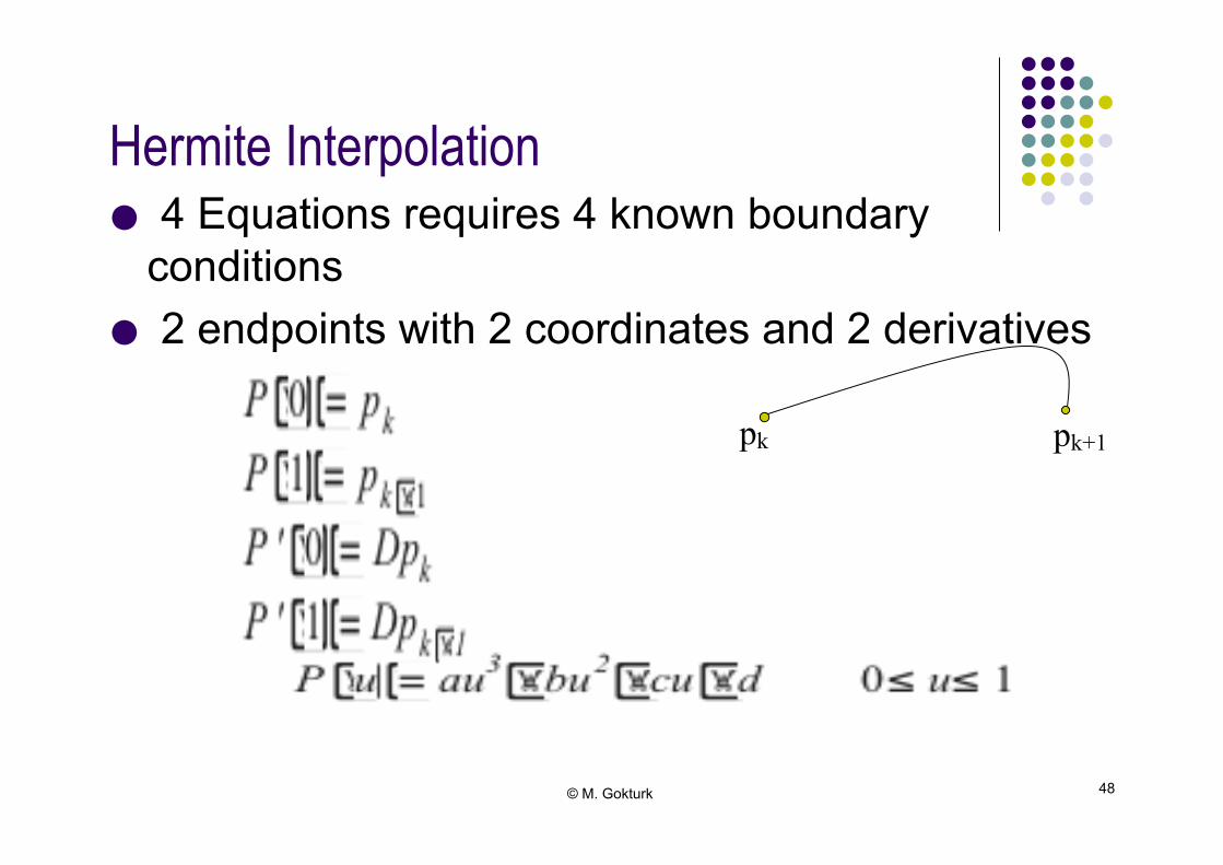
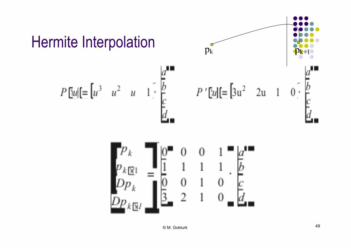
Hermite Interpolation!
● 4 Equations requires 4 known boundary conditions
● 2 endpoints with 2 coordinates and 2 derivatives!
pk pk+1
© M. Gokturk 49
Hermite Interpolation! pk pk+1
© M. Gokturk 50
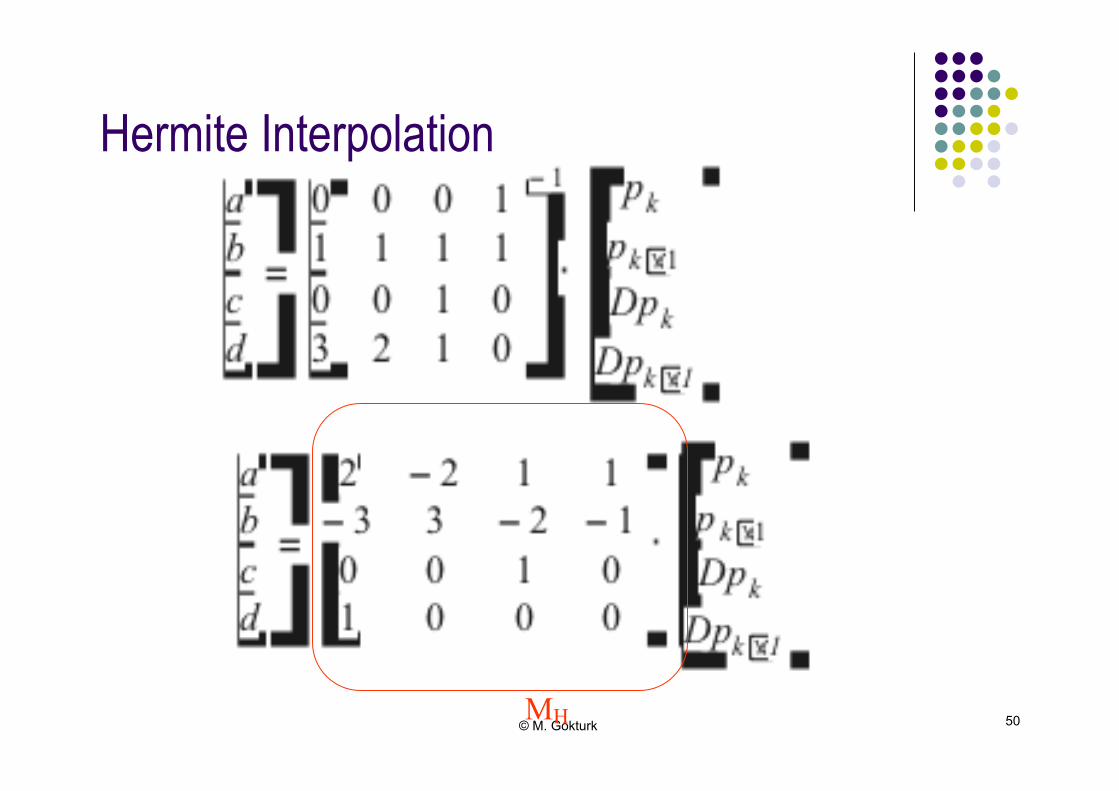
Hermite Interpolation!
MH
© M. Gokturk 51
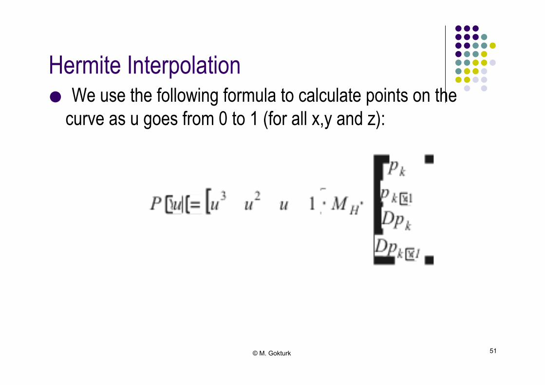
Hermite Interpolation!
● We use the following formula to calculate points on the curve as u goes from 0 to 1 (for all x,y and z):!

© M. Gokturk 52
Other Types of Splines!
● Lagrange (Interpolation Scheme) ● Kochanek-Bartel (Interpolation Scheme) ● Catmull-Rom (Interpolation Scheme) ● Bézier (Approximation Scheme) ● B-spline (Approximation Scheme) ● Beta Splines (Interpolation Scheme) ● Cardinal Splines (Interpolation Scheme) ● Rational Splines (Approximation Scheme)
● These will be studied in COMP304!
© M. Gokturk 53
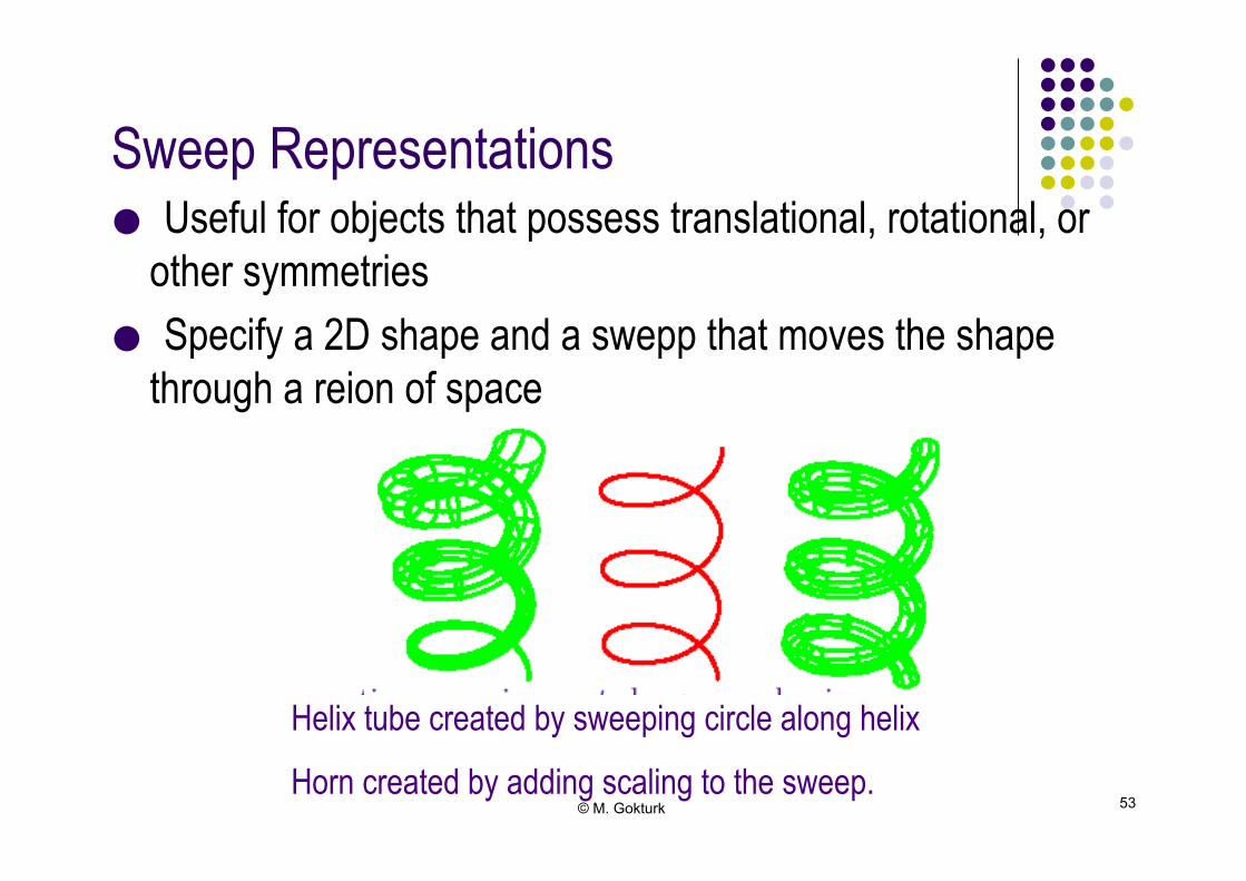
Sweep Representations!
● Useful for objects that possess translational, rotational, or other symmetries
● Specify a 2D shape and a swepp that moves the shape through a reion of space!
Helix tube created by sweeping circle along helix
Horn created by adding scaling to the sweep.
© M. Gokturk 54
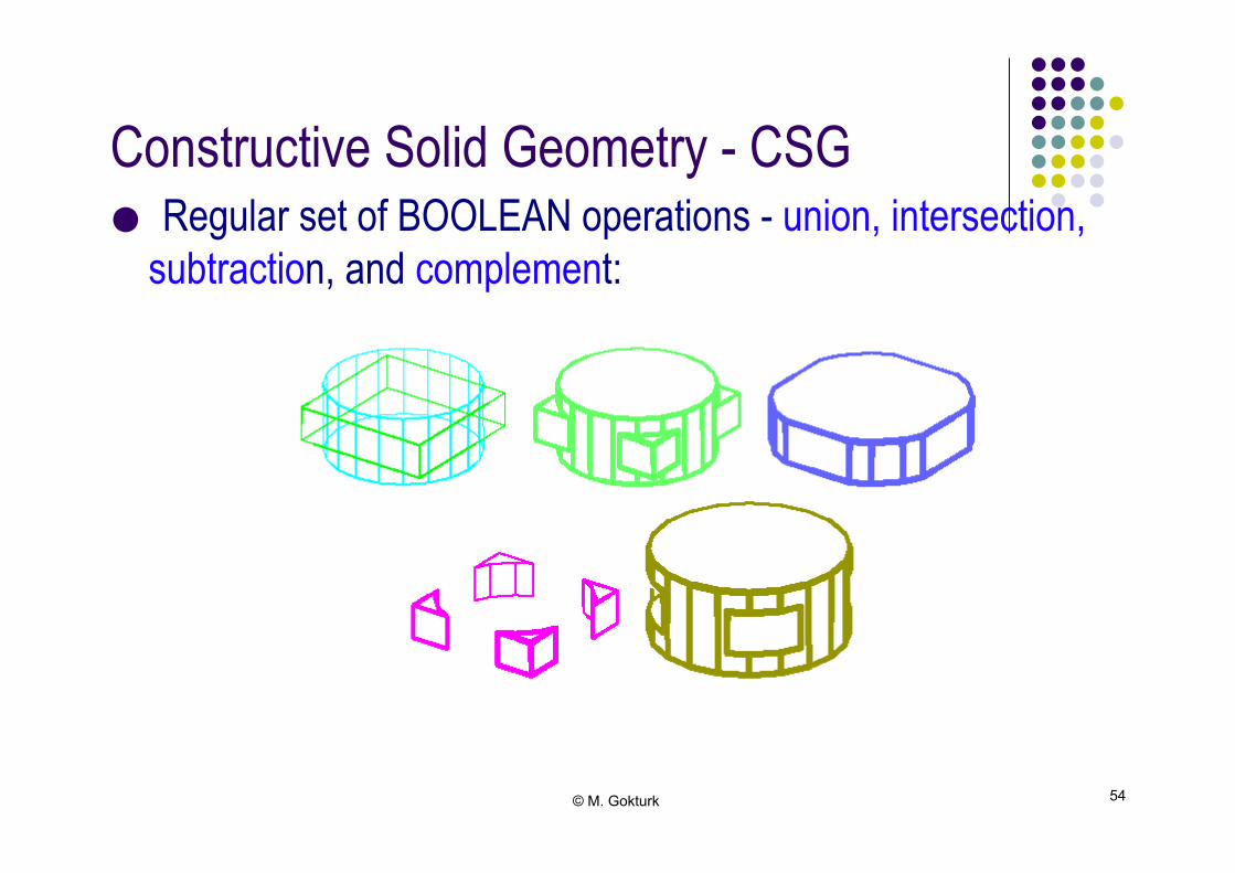
Constructive Solid Geometry - CSG!
● Regular set of BOOLEAN operations - union, intersection, subtraction, and complement:!
© M. Gokturk 55
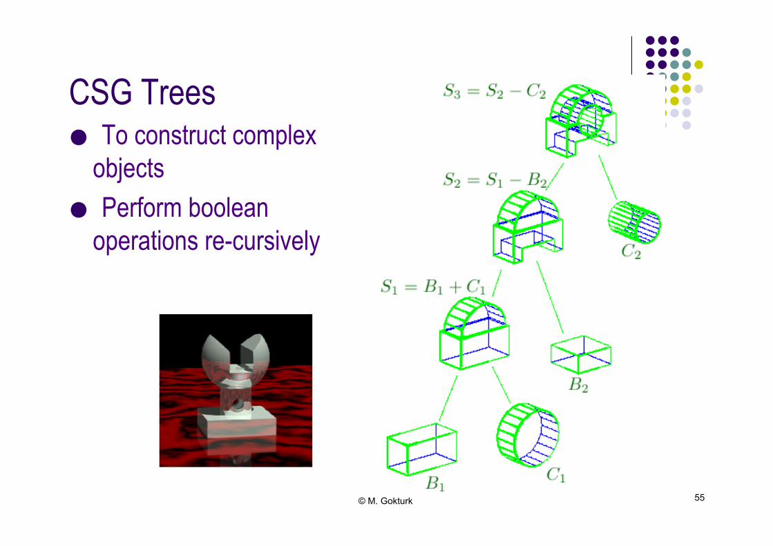
CSG Trees!
● To construct complex objects
● Perform boolean operations re-cursively!
© M. Gokturk 56
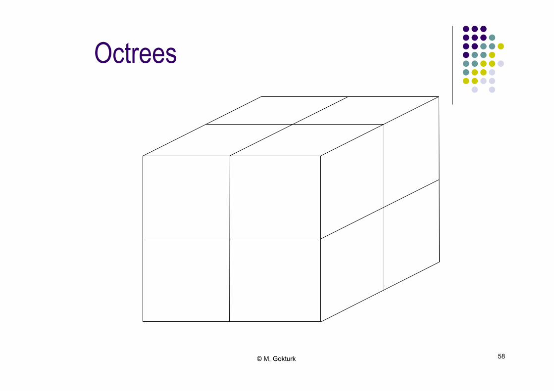
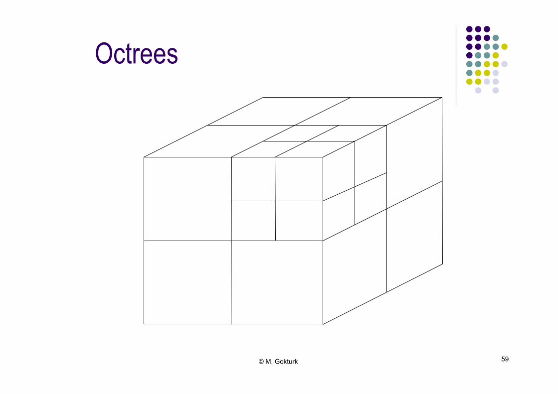
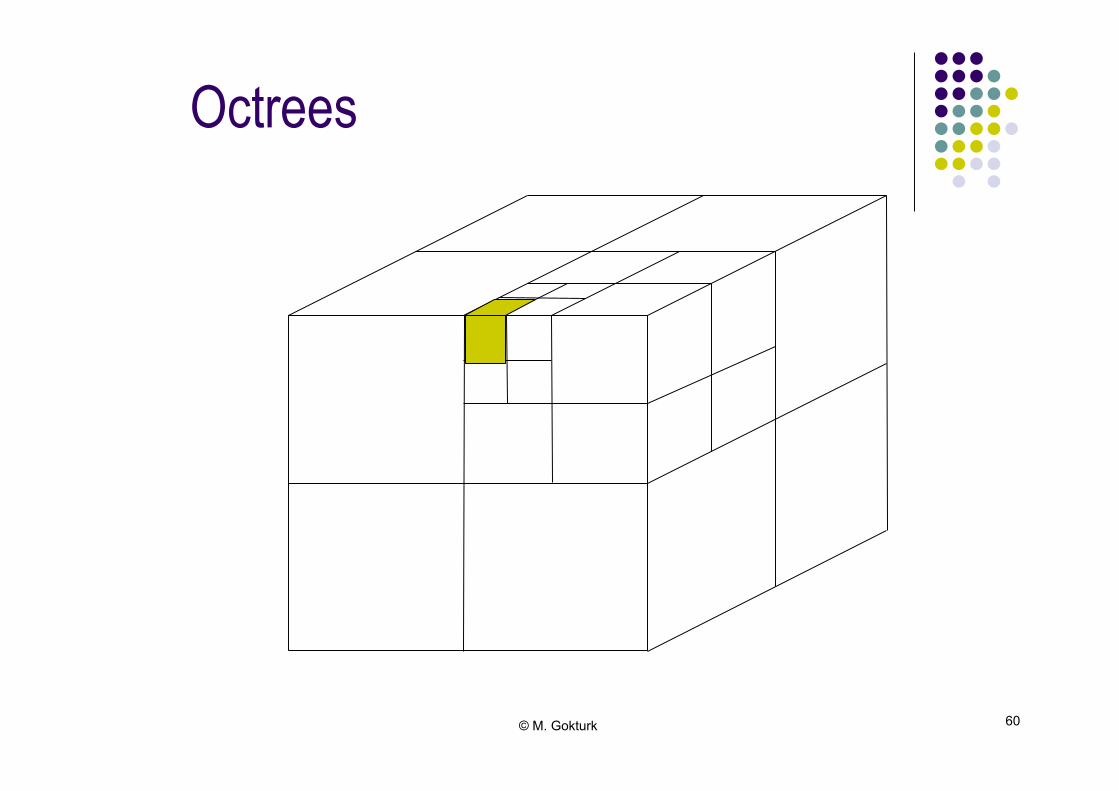
Octrees!
● Used to subdivide space recursively ● Hieracrhical tree structure representing solid objects ● Each node corresponds to a space in 3D space ● Convenient way to store large object information in 3D ● EXAMPLE: Medical imaging data ● 2D version is called Quadtree!
© M. Gokturk 57
Octrees!
?
© M. Gokturk 58
Octrees
© M. Gokturk 59
Octrees
© M. Gokturk 60
Octrees
© M. Gokturk 61
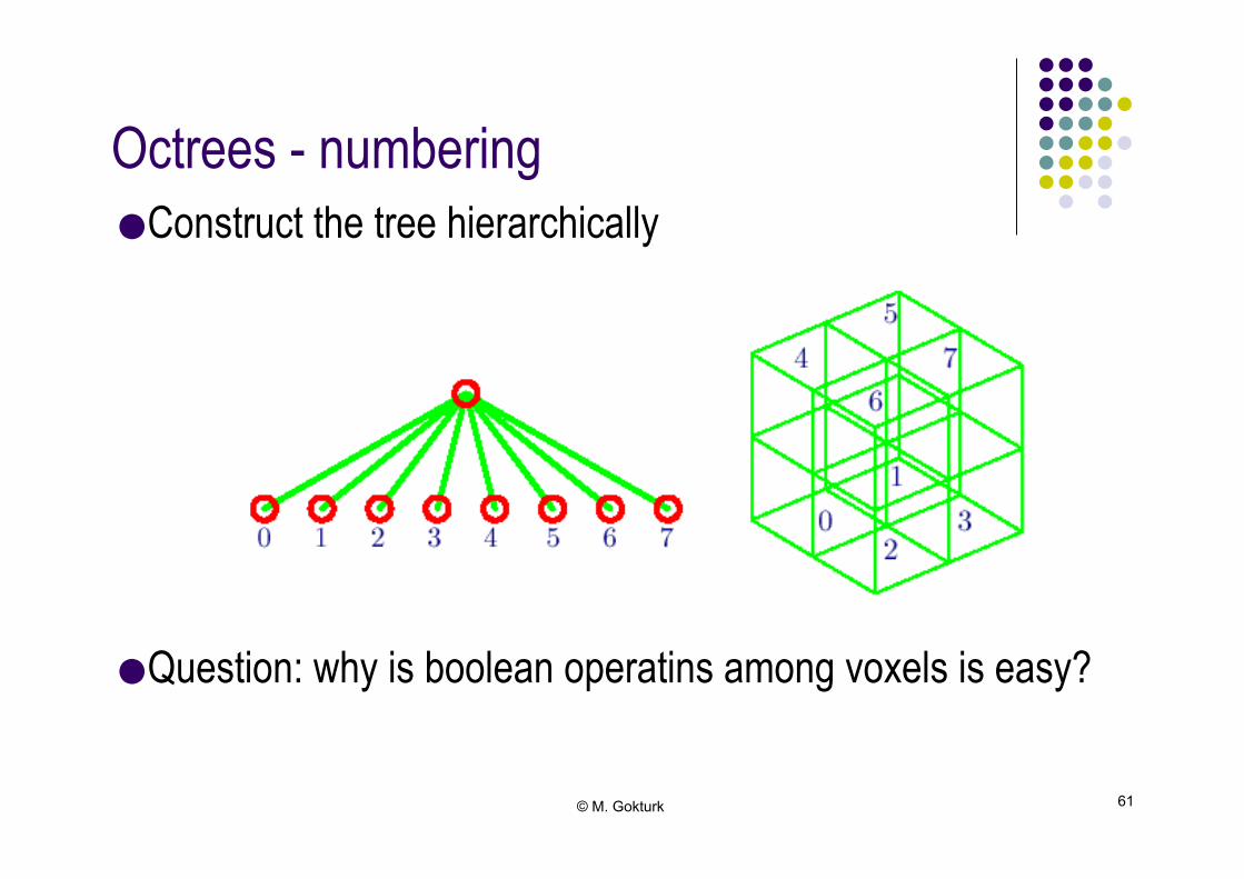
Octrees - numbering!
● Construct the tree hierarchically ● Question: why is boolean operatins among voxels is easy?

© M. Gokturk 62
Quadtrees!
● Data structure for storage of 2D data by successive subdivision of regions into quadrants ● Leaf quadrants contain uniform data (full/empty) ● Non-uniform quadrants are subdivided further!
© M. Gokturk 63
Fractal Based Modeling!
● Self Similarity Function ● Randomized Fractals ● Simple Example ● Start with a simple line!
© M. Gokturk 64
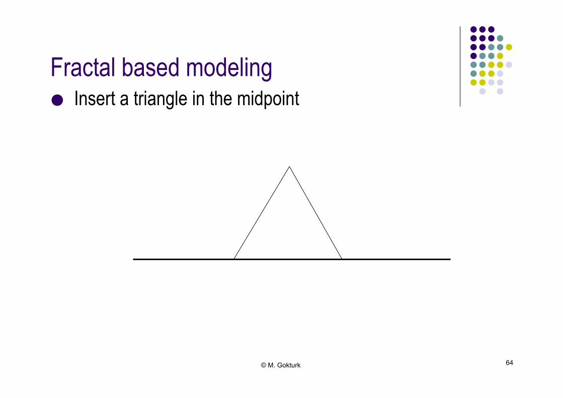
Fractal based modeling!
● Insert a triangle in the midpoint!
© M. Gokturk 65
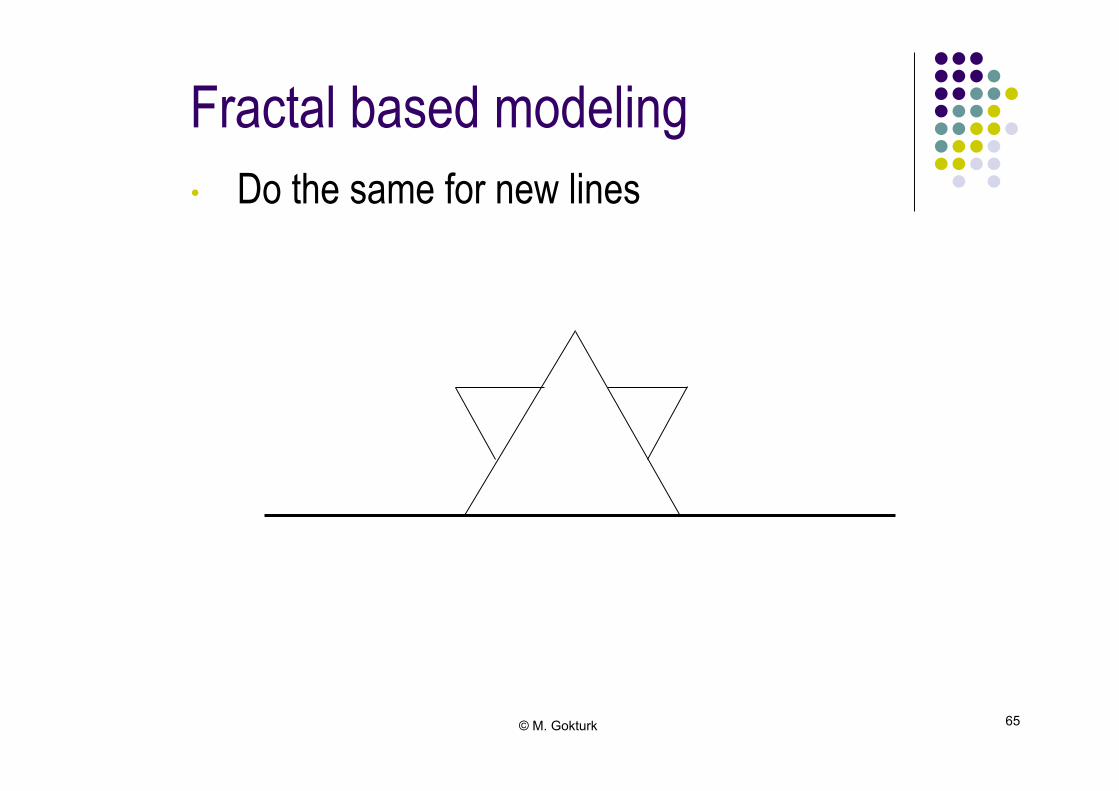
Fractal based modeling
• Do the same for new lines
© M. Gokturk 66
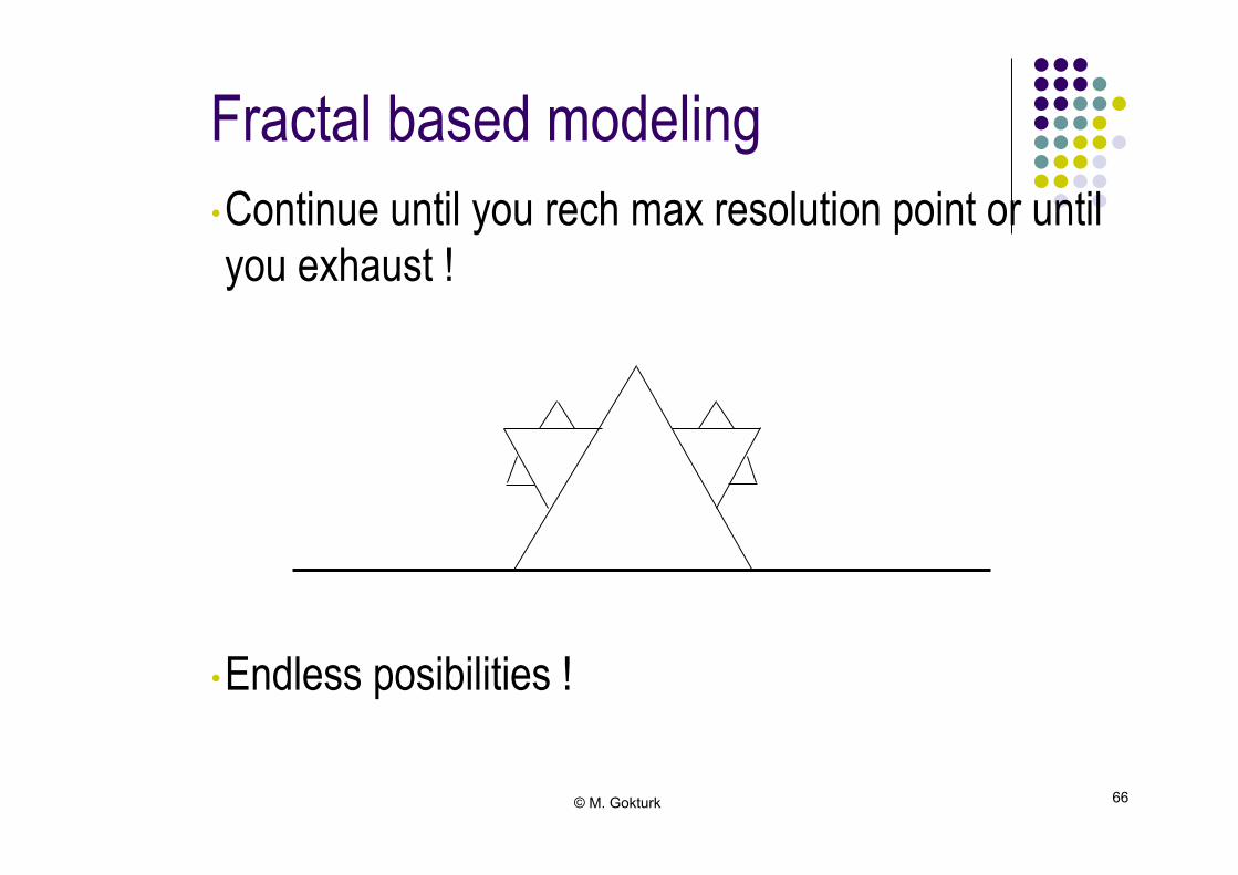
Fractal based modeling
• Continue until you rech max resolution point or until you exhaust !
• Endless posibilities !
© M. Gokturk 67
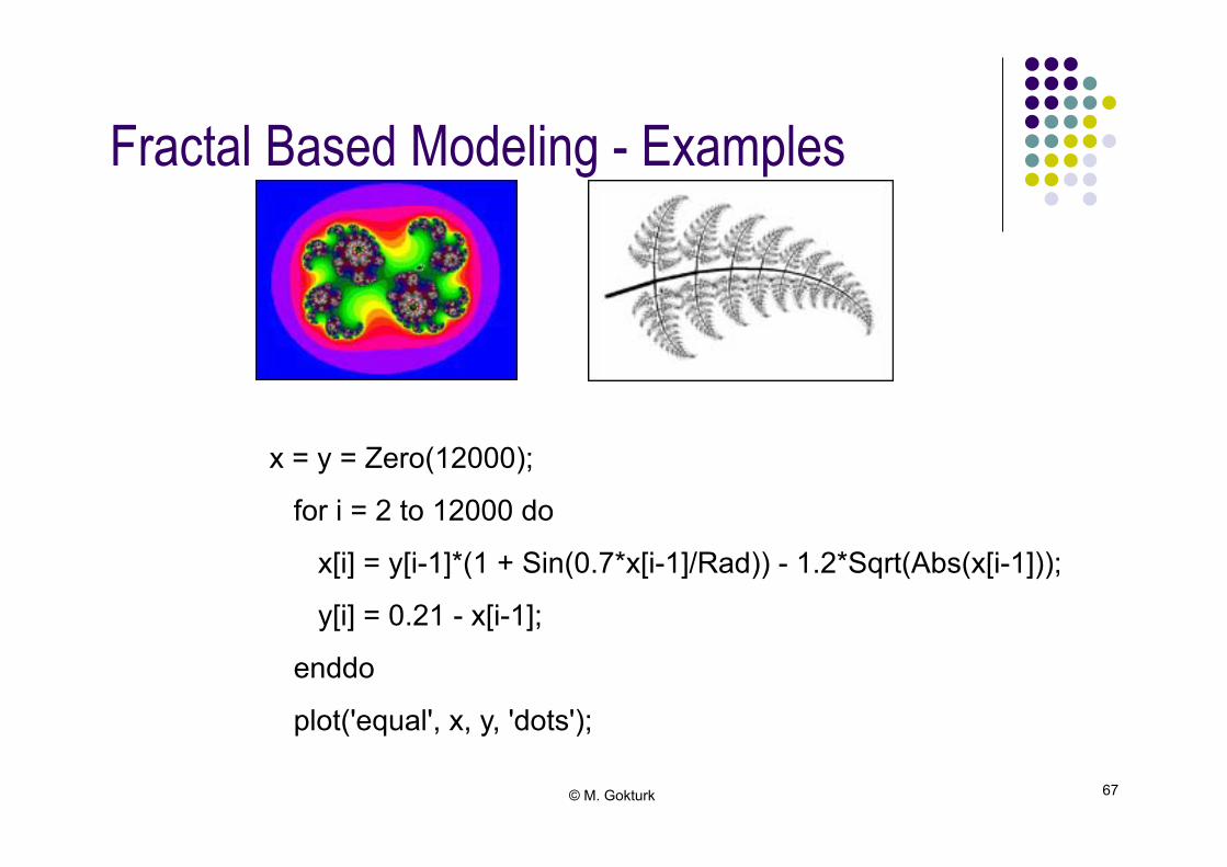
Fractal Based Modeling - Examples!
x = y = Zero(12000);
for i = 2 to 12000 do
x[i] = y[i-1]*(1 + Sin(0.7*x[i-1]/Rad)) - 1.2*Sqrt(Abs(x[i-1]));
y[i] = 0.21 - x[i-1];
enddo
plot('equal', x, y, 'dots');
© M. Gokturk 68
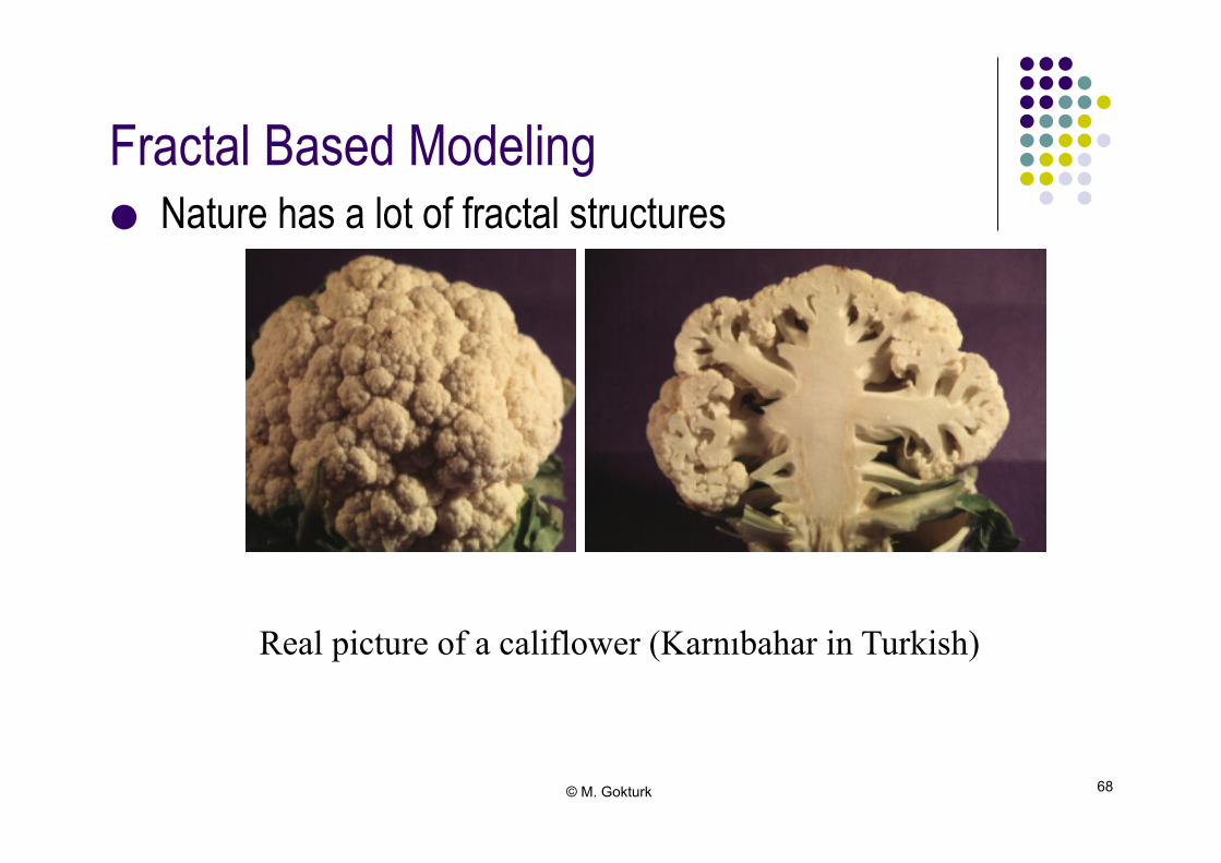
Fractal Based Modeling!
● Nature has a lot of fractal structures!
Real picture of a califlower (Karnıbahar in Turkish)
© M. Gokturk 69
Other methods!
● Particle Systems ● Physically Based Modeling ● Data visualization modeling - These will be studied in future courses!
© M. Gokturk 70
Questions ?!
● Homeworks? ● You must read the book! ● Get a good grade, not a passing grade.!