Embed Size (px)
Citation preview

Computer Fundamentals
ELEC 330
Digital Systems Engineering
Dr. Ron Hayne

330_01 2
Review of Number Systems
Number Systems (Conversions) Binary Octal Hex
Negative Numbers Two’s Complement Sign Extension
Arithmetic Addition (Subtraction)
Codes BCD ASCII
330_01 3
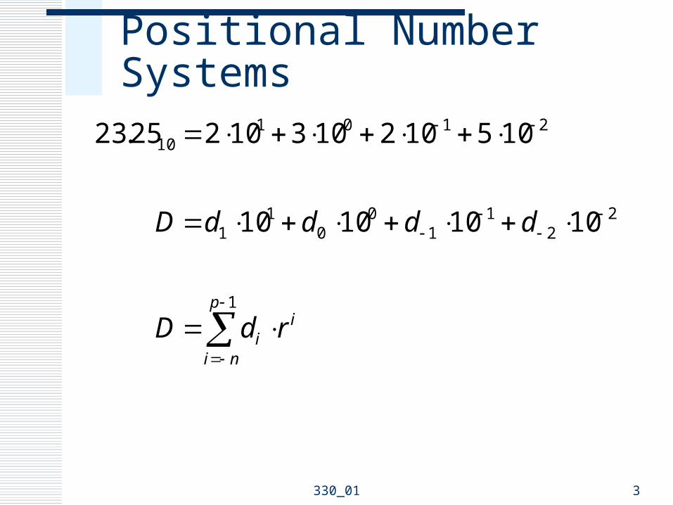
Positional Number Systems
1
22
11
00
11
210110
10101010
10510210310225.23
p
ni
ii rdD
ddddD

330_01 4
Binary
10
210122
22
11
00
11
22
1
25.5
25.015.00112041
212021202101.101
22222
2
bbbbbB
bBp
ni
ii

330_01 5
Number Systems

330_01 6
Octal and Hexadecimal
16
22
8
22
4.2
]0100].[1100][0010[01.101100
2.54
]010].[100][101[01.101100
C

330_01 7
Octal and Hexadecimal
10
10116
10
1018
10
2
25.44
16416121624.2
25.44
8284852.54
25.44
25.0483201.101100
C
330_01 8
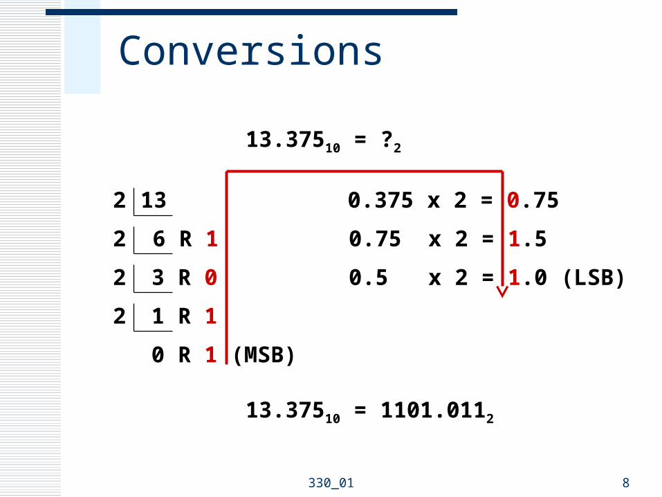
Conversions
13.37510 = ?2
132
6 R 12
3 R 02
1 R 12
0 R 1 (MSB)
0.375 x 2 = 0.75
0.75 x 2 = 1.5
0.5 x 2 = 1.0 (LSB)
13.37510 = 1101.0112

330_01 9
Binary Addition (Full Adder)
CIN X Y COUT S
0 0 0 0 0
0 0 1 0 1
0 1 0 0 1
0 1 1 1 0
1 0 0 0 1
1 0 1 1 0
1 1 0 1 0
1 1 1 1 1
330_01 10
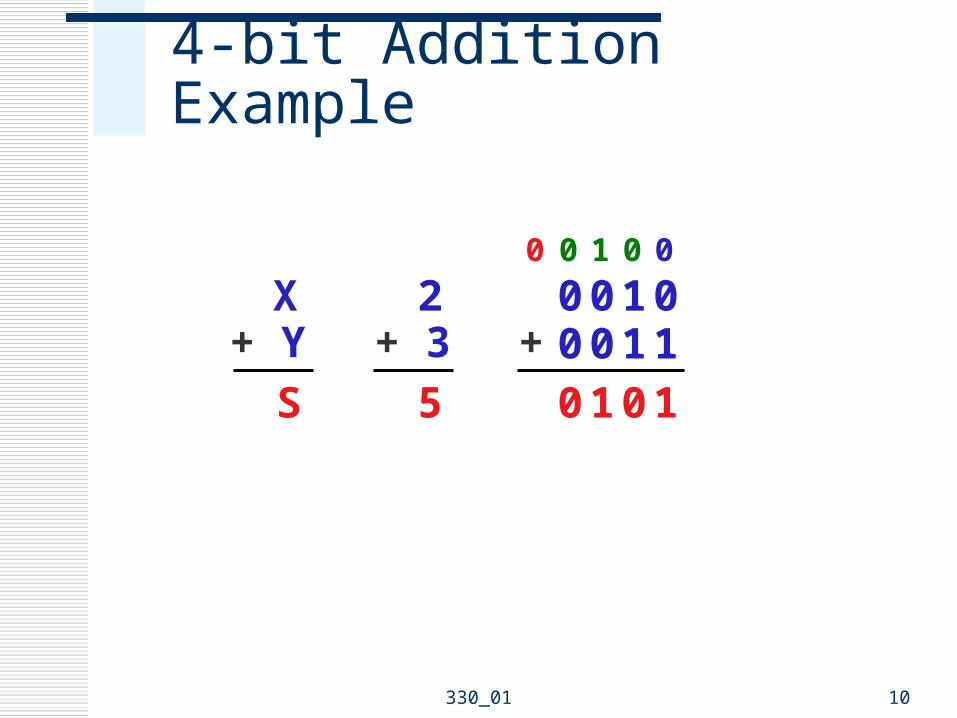
4-bit Addition Example
X+ Y
S
0+
1001100
0
1
0
0
1
1
0
0
0
2+ 3
5

330_01 11
Negative Numbers

330_01 12
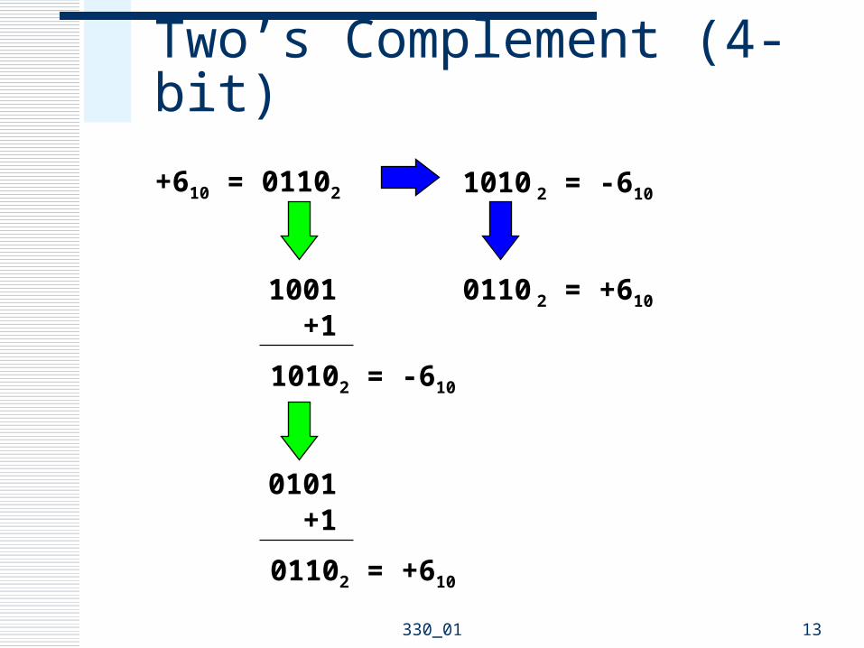
Two’s Complement
MSB serves as sign bit (fixed-width) 0 => positive 1 => negative
Negation Operation Complement all bits Add 1
Alternate Negation Operation Starting from right to left
Copy up to and including the first 1 Complement the rest
330_01 13
2 = -610
2 = +610
Two’s Complement (4-bit)
+610 = 01102
1001 +1
10102 = -610
1010
0101 +1
01102 = +610
1001

330_01 14
Two’s Complement Arithmetic
Examples (4-bit)
3 - 6 = -3
-4 - 5 = ?

330_01 15
Overflow
Operation produces a result that exceeds the number system
Example (4-bits) Range -8 to +7
Detection Rule Overflow occurs if the addends’ signs are the
same, but the sum’s sign is different from the addends’
330_01 16
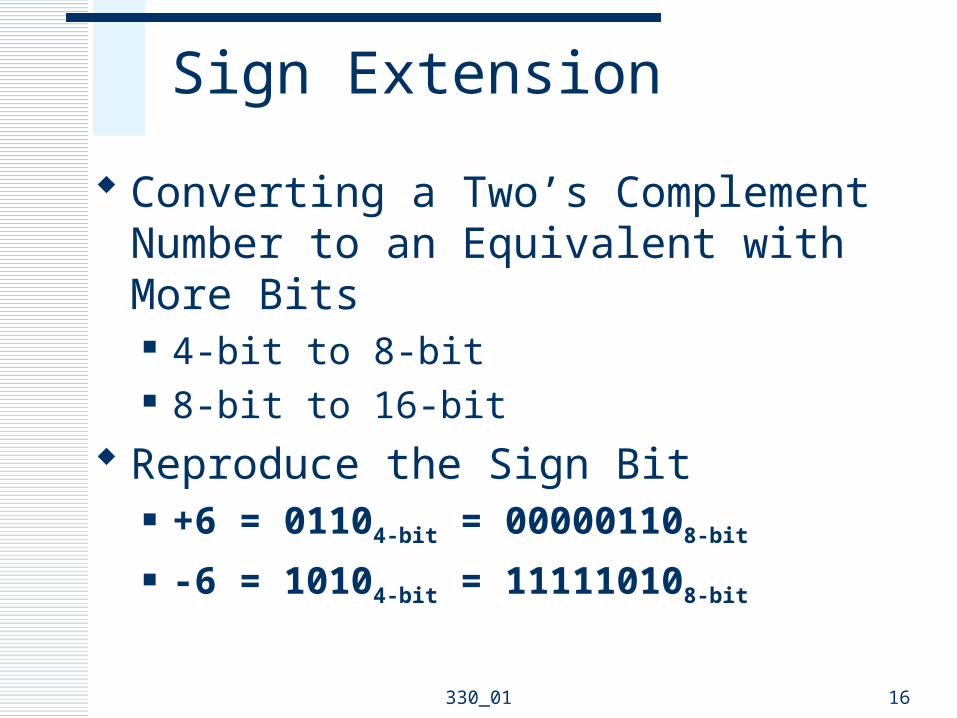
Sign Extension
Converting a Two’s Complement Number to an Equivalent with More Bits 4-bit to 8-bit 8-bit to 16-bit
Reproduce the Sign Bit +6 = 01104-bit = 000001108-bit
-6 = 10104-bit = 111110108-bit

330_01 17
Binary-Coded Decimal (BCD)
Encodes digits 0 thru 9 4-bit unsigned binary
0000 thru 1001
6 unused code words 1010 thru 1111
Packed BCD 8-bit byte 2 BCD digits

330_01 18
BCD Arithmetic
Correction made if result exceeds 1001 Add 6 Produces carry
36 0011 0110+ 27 + 0010 0111 63 0101 1101 + 0000 0110 0110 0011
330_01 19
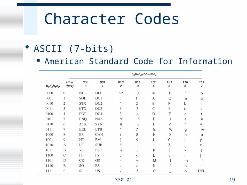
Character Codes
ASCII (7-bits) American Standard Code for Information Interchange

330_01 20
Summary
Number Systems (Conversions) Binary Octal Hex
Negative Numbers Two’s Complement Sign Extension
Arithmetic Addition (Subtraction)
Codes BCD ASCII

330_01 21
Digital Systems
Logic Gates Building Blocks
Combinational Sequential Memory
Examples Synchronous Serial Communications Instruction-controlled Information Processor

330_01 22
Logic Gates
X Y X Y
X_

330_01 23
More Logic Gates
X Y_____
X Y_____

330_01 24
Binary Decoder (n-to-2n)
Activates exactly one of 2n outputs based on an n-bit input value

330_01 25
Multiplexer
Digital Switch Selects 1 of n sources Based on s control lines n = 2s Sources b bits wide

330_01 26
Arithmetic Logic Unit (ALU)
330_01 27
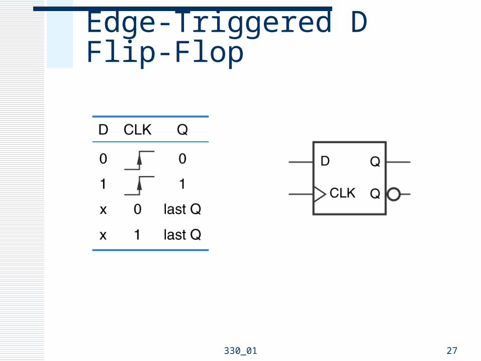
Edge-Triggered D Flip-Flop

330_01 28
4-bit Binary Counter
Synchronous Active-low Load Active-low Clear
Two Enables ENP (parallel) ENT
Ripple Carry Out RCO (ENT) Cascading
330_01 29
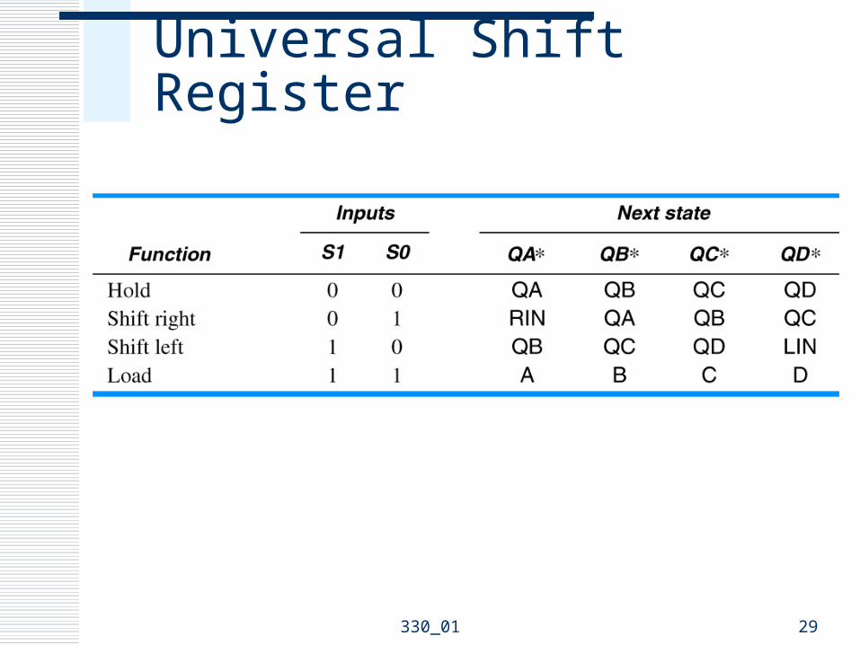
Universal Shift Register

330_01 30
Register Notation
Serial Transfer
Parallel Transfer
Register Contents
RC Logical Shift Left0
R
1 0 1 1 0 1 0 1 B 5

330_01 31
Buses and Transfer Gates
Transfer
Transfer
Transfer
88

330_01 32
Memory Organization
Dimensions n-bit words k-bit address
Operations Read, Load, Fetch Write, Store
Memory
first word
next word
last word
n bitsAddress
0
1
2k-1
.
.
.
330_01 33
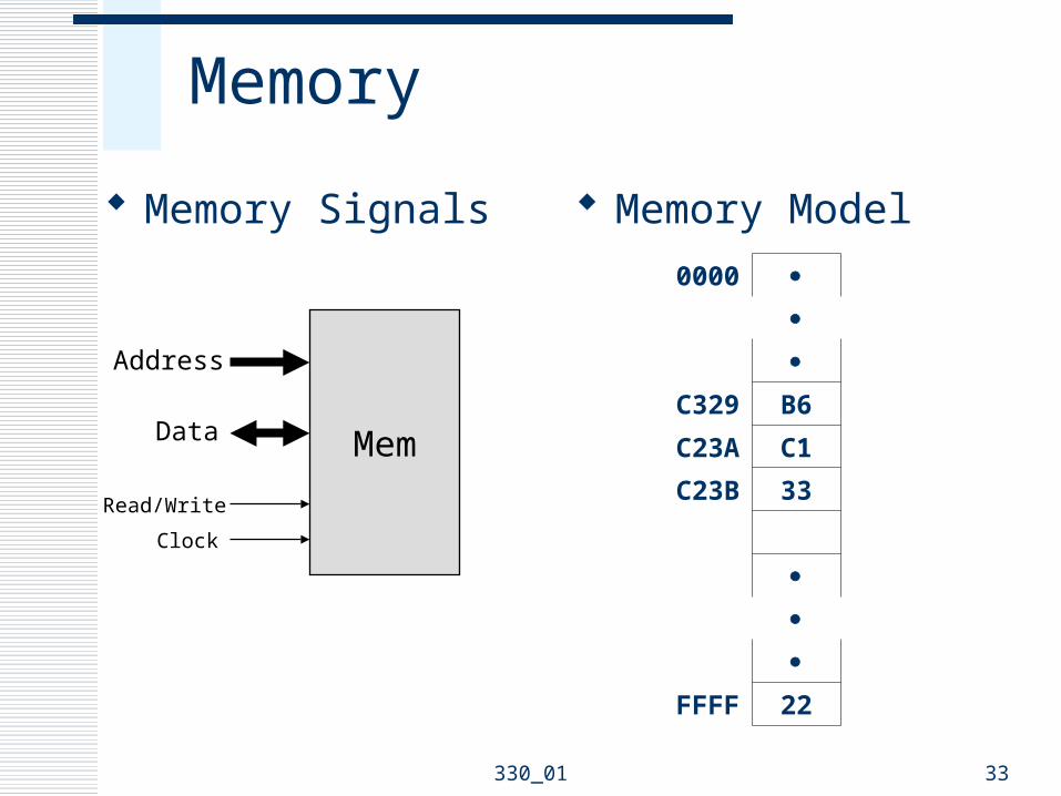
Memory
Memory Signals Memory Model
Mem
Address
Data
Read/Write
Clock
0000
C329 B6
C23A C1
C23B 33
FFFF 22

330_01 34
Example Digital System
Synchronous Serial Communications
Parallel Register Parallel Register
Shift RegisterShift Register
ControlUnit
CountF
Slave DeviceMaster Device
Transmit
Receive
Clock

330_01 35
Example Digital System
Instruction-controlled Information Processor Arithmetic Logic Unit Registers Transfer Gates Input Port Output Port Control Unit

ALU
A B
OU
T
Processor
XIN
LA LB
XA XB
LOUT
C0C1
ControlUnit
C0C1
XAXBLALB
XINLOUT
Clock
OUT
IN
C0 C1 Operation
00 IN1 + IN2 OUT
01 IN1 + IN2 + 1 OUT
10 IN1 + IN2 OUT
11 IN1 + IN2 + 1 OUT

330_01 37
System Operation
IN - B OUT
Control Signals
Step RTL XIN LA LB XA XB C0 C1 LOUT
1 IN A 1 1 0 0 0 0 0 0
2 A - B A 0 1 0 1 1 1 1 0
3 A OUT X 0 0 X X X X 1
330_01 38
Summary
Logic Gates Building Blocks
Combinational Sequential Memory
Examples Synchronous Serial Communications Instruction-controlled Information Processor

330_01 39
Processors
Stored Program Processors General-Purpose Computers Microprocessors Microcomputers Microcontrollers

330_01 40
Building Blocks
Clock Processor
ALU Registers
Control Unit Memory Input/Output

330_01 41
Stored Program Processor
Input/Output
ProcessorControl
Unit
In
Out
Data
Memory
Data
Control
Instruction
Control/StatusClock

330_01 42
Memory
Instructions Program Software
Data Load Store
Memory Model
0000
C329 B6
C23A C1
C23B 33
FFFF 22
330_01 43
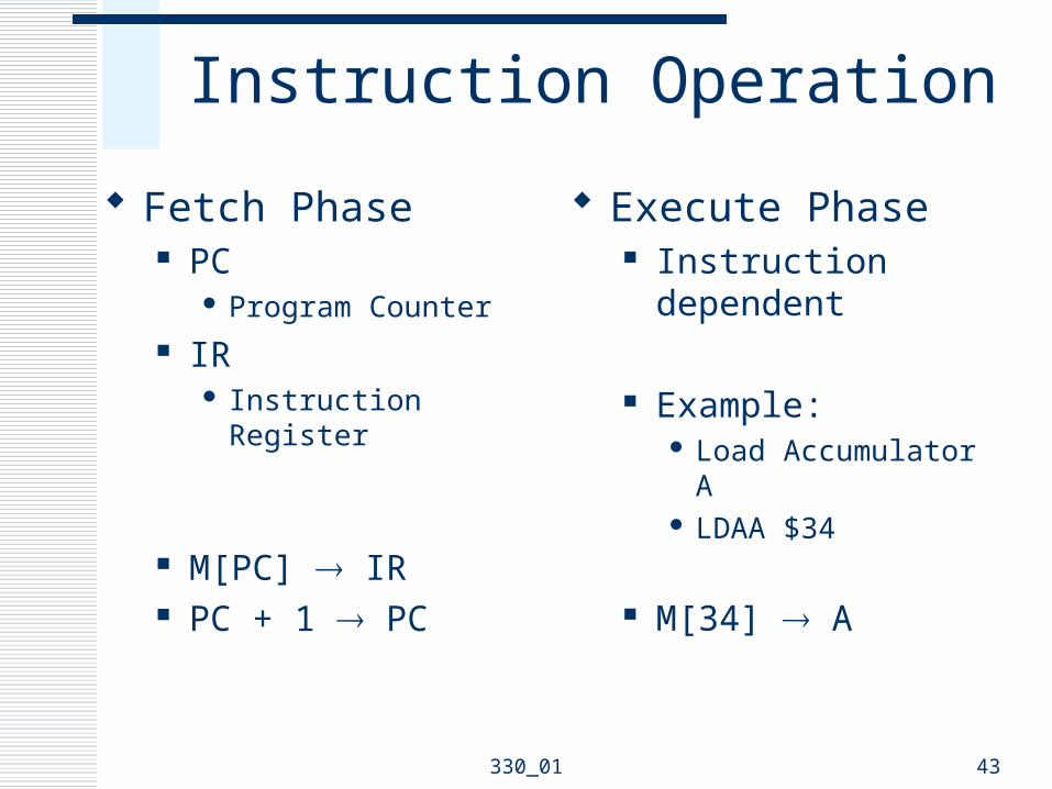
Instruction Operation
Fetch Phase PC
Program Counter IR
Instruction Register
M[PC] IR PC + 1 PC
Execute Phase Instruction dependent
Example: Load Accumulator A LDAA $34
M[34] A

330_01 44
General-Purpose Computer
Arithmetic Operations Logical Operations Load and Store Operations Testing and Branching Input and Output

330_01 45
Computer Architecture
Princeton von Neumann
Memory holds both instructions and data
Input/Output
ProcessorControl
Unit
In
Out
Data
Memory
Data
Control
Instruction
Control/StatusClock

330_01 46
Computer Architecture
Harvard Separate instruction
and data memories
Input/Output
ProcessorControl
Unit
In
Out
Data
DataMemory
Data
Control
Instruction
Control/StatusClock
InstructionMemory

330_01 47
Microprocessor/Microcomputer
Microprocessor Single Integrated Circuit (IC) Processor and Control Unit
Microcomputer Single Printed Circuit Board
Interconnection of multiple ICs Microprocessor, Memory, I/O, Clock
Microcontroller Single-Chip Microcomputer

330_01 48
Microcomputer/Microcontroller
Input/Output
ProcessorControl
Unit
Memory
ClockMicrocomputer/Microcontroller
Microprocessor

330_01 49
Embedded Control Systems
Microcomputer inside a device that is not called a computer Satellite TV Receivers Microwave Ovens Programmable Thermostats Automobiles Robotics

330_01 50
Personal Computers
PC Collection of components that contain many
microcomputersCentral Microcomputer (CPU)Keyboard ControllerDisk Drive InterfaceDisplay Monitor InterfacePrinter

330_01 51
Summary
Stored Program Processors General-Purpose Computers Microprocessors Microcomputers Microcontrollers