Embed Size (px)
Citation preview

ADVANCES IN MANUFACTURING SCIENCE AND TECHNOLOGY Vol. 37, No. 2, 2013
DOI: 10.2478/amst-2013-0013
Address: Bogdan SŁODKI, Ph.D. Eng., Cracow Uniwersity of Technology, Production Engineering Institute, Jana Pawła II 37, 31-864 Cracow, phone (0-48, 12) 437-32-12, fax: (0-48, 12) 374-32-02, e-mail: [email protected]
COMPUTER DECISION SUPPORT SYSTEM STRUCTURE FOR MACHINING DATA SELECTION IN TURNING
Bogdan Słodki
S u m m a r y
The paper presents the structure of a complex system for supporting a decision making process in machining data selection in turning operations. It is assumed, that the system modules cooperate with each other, utilize data and knowledge bases through the information bus. The system proposes to use on line information from visual monitoring module equipped with high speed camera what enables to observe chip forms. Particular modules and their tasks in the system are described as well as some examples are described.
Keywords: turning, superalloys, chips, monitoring
Struktura systemu wspomagania decyzji w doborze parametrów skrawania dla toczenia
S t r e s z c z e n i e
W pracy przedstawiono strukturę systemu wspomagania decyzji w doborze parametrów skrawania dla toczenia. Budowa systemu zakłada współdziałanie wielu modułów – stosowanie baz danych i wiedzy połączonych magistralą informacyjną. System wykorzystuje informację z modułu monitorowania procesu skrawania wyposażonego w kamerę szybkoklatkową umożliwiające obserwację postaci i kształtu powstającego wióra. Przedstawiono zadania poszczególnych modułów systemu i przykłady ich działania.
Słowa kluczowe: toczenie, superstopy, wióry, monitorowanie
1. Introduction
Taking into account complexity of phenomena taking place in machining and the fact that the influence of particular elements of machining system (tool-lathe-work piece) on tool life is not precisely defined, it is not an easy task to define optimum machining parameters [1] in local operating features.
It seems to be clear that machining data selection must be based on an advisory system consisting of many modules cooperating with each other. Each module task is to provide partial solution. Many commercial programs (CoroGuide by Sandvik Coromant, Wintoms by Kennametal) do not give

24 B. Słodki
solutions for all needed cases. Usefulness and correctness of such a system depends in practice on its user opinion.
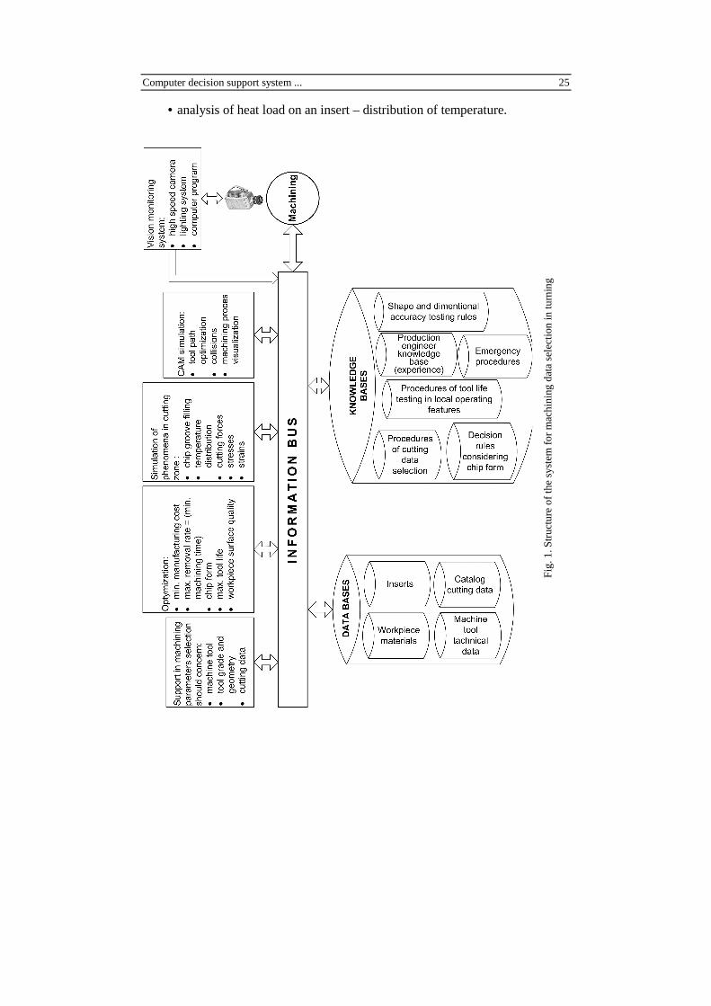
2. System structure
To fulfill necessary for rational selection of machining data needs, a system providing the flow of information and knowledge must be set up.
The structure of such a system is presented in Fig. 1. The system should include various computer programs using data and knowledge bases.
The proposed structure consists of two parts connected with information bus, because each module should have access to all information included in the system.
The first part (data and knowledge bases) should contain recommendations of tool manufacturers concerning cutting data and inserts as well as recommendations of work piece materials producers.
Production engineer experience, which is difficult to formalize, (can be named his knowledge base) is also important.
A data base concerning operational data of available machine tools can enable to choose a proper one for a given task.
The machining process should be monitored by sending information about its actual state, so it is necessary to equip the system with vision monitoring. Components of cutting force and temperature measurement systems have really limited application in industry but on the other hand they are very important in scientific research.
Data processing belongs to the second group of modules. The group consists of modules for:
• support in the selection of machining parameters especially in local operating features [2, 3],
• optimization of various process components, like chip forms, tool life, • simulation and modeling of various phenomena taking place in cutting
zone, • computer aided manufacturing (CAM) simulation, • vision machining process monitoring system. Modeling and a simulation module should realize various tasks described in
[4-11]. The simulation module should include material model of a tool and work piece and geometrical model with boundary limits.
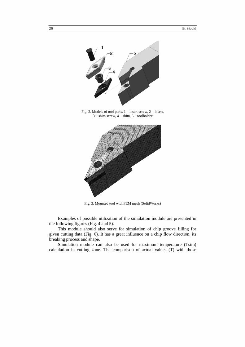
3-D tool geometrical models are especially useful [12]. They enable to: • tool visualization – an example of turning tool model is presented in
Fig. 2 and 3, • strain analysis and stress analysis resulting from the value of cutting force
received from measurement equipment or calculated on the basis of theoretical formulas – based on catalogue data,
Computer decision support system ... 25
• analysis of heat load on an insert – distribution of temperature.
Fig
. 1. S
tru
ctu
re o
f th
e sy
stem
for
mac
hin
ing
dat
a se
lect
ion
in t
urn
ing
26 B. Słodki
Fig. 2. Models of tool parts. 1 – insert screw, 2 – insert, 3 – shim screw, 4 – shim, 5 – toolholder
Fig. 3. Mounted tool with FEM mesh (SolidWorks)
Examples of possible utilization of the simulation module are presented in the following figures (Fig. 4 and 5).
This module should also serve for simulation of chip groove filling for given cutting data (Fig. 6). It has a great influence on a chip flow direction, its breaking process and shape.
Simulation module can also be used for maximum temperature (Tsim) calculation in cutting zone. The comparison of actual values (T) with those

Computer decision support system ... 27
calculated in the simulation module [9] shows usefulness of the described method.
a)
b)
c)
Fig. 4. Examples of FEM analysis for defining dependence of stress distribution from the feed value [4]: a) f = 0.2 mm/rev, b) f = 0.3 mm/ rev, (Unigraphics 7), darker areas show bigger stress on the cutting edge, c) example of distribution of heat load on the rake face of an insert in selected nodes, (SolidWorks)
a) b) c) d)
Fig. 5. An example of sections of an insert in various depth of a cut in tool-in-use system: a) cutting planes marked on the rake face, (CATIA V5), b) ap = 0.5 mm, c) ap = 1.5 mm, d) ap = 2.5 mm. This enables to measure actual chip breaker dimensions

28 B. Słodki
Figure 7 presents example results achieved for different 6 sets of cutting data (Table 1) in turning Inconel 718 (set 1 and 2) and Inconel 625 (the other sets).
a)
b)
Fig. 6. Simulation of turning Inconel 718 alloy. Tool geometry based on measurement of insert computer model and its section [9]
X, mm
X, mm

Computer decision support system ... 29
Fig. 7. Comparison of measured temperature with temperature achieved from computer simulation [10]
Table 1. Cutting data used in simulation [10]
Test number Work piece material
Feed rate f, mm/rev
Cutting speed vc
m/min Depth of cut ap
mm
1 Inconel 718
0.211 75
2 2 50 3
Inconel 625
75 4 0.153
65 1.5
5 0.077 0.5 6 0.249
The vision monitoring system can be used to verify the correctness of
cutting data selection and their influence on the chip form. Two examples of chips photographs taken by means of high speed camera during the stainless steel (4H13) longitudinal turning are presented in Fig. 8.

30 B. Słodki
Fig. 8. Examples of chip forms in 4H13 steel turning: vc = 240 m/min, ap = 1,5 mm, recording 1600 fps: a) incorrect chip form, f = 0,105 mm/rev, b) correct chip form, f = 0,307 mm/rev
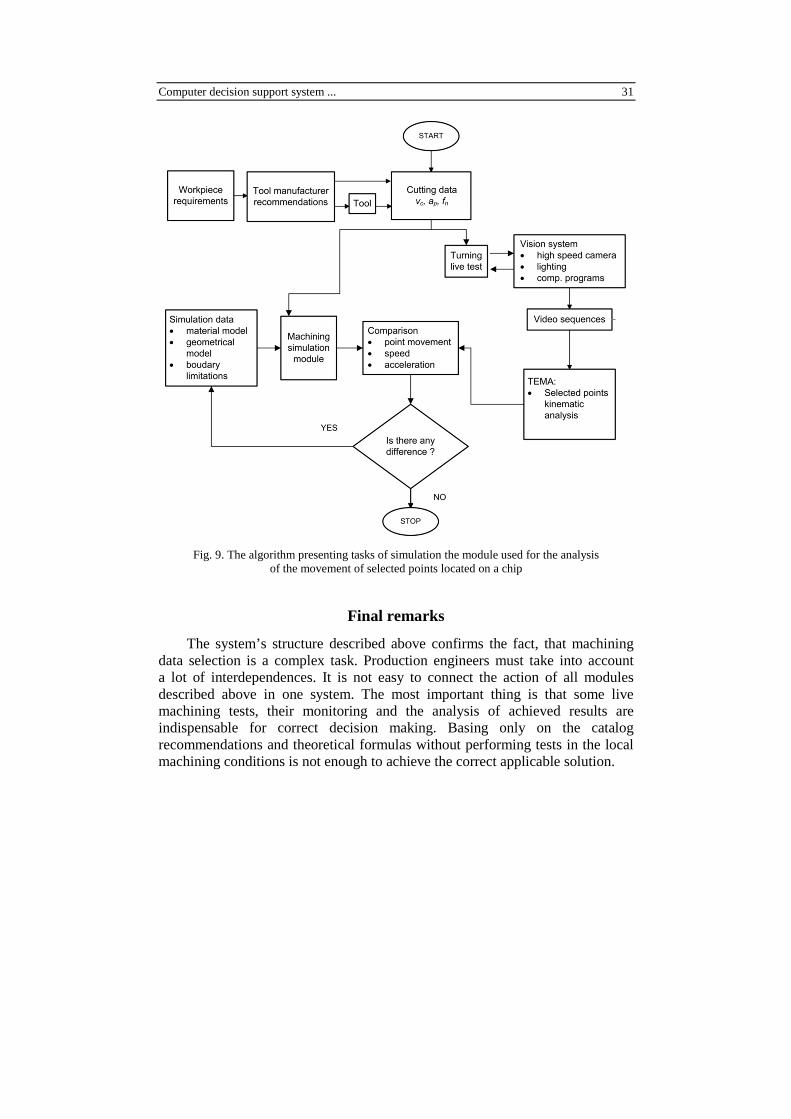
If the system is equipped with high speed camera coupled with computer program for the movement analysis (e.g. TEMA by Vision Research), it is possible to use the simulation module in the system structure like it is shown in Fig. 9.
In the case of numerical calculations application it is necessary to apply experimental verification of the simulation module correctness. The cut selected points (located on a chip) movement should be subjected to examination. Kinematic analysis can take into account the movement (trajectory), speed and acceleration of these points in a determined period of time. If there is a significant difference between simulated and actual values, it is necessary to modify simulation parameters for material and geometrical models and correct boundary limits mainly in the contact zone between cutting edge and chip (e.g. a friction coefficient). This approach can be helpful to adjust simulation module parameters to the real ones.
Computer decision support system ... 31
Fig. 9. The algorithm presenting tasks of simulation the module used for the analysis
of the movement of selected points located on a chip
Final remarks
The system’s structure described above confirms the fact, that machining data selection is a complex task. Production engineers must take into account a lot of interdependences. It is not easy to connect the action of all modules described above in one system. The most important thing is that some live machining tests, their monitoring and the analysis of achieved results are indispensable for correct decision making. Basing only on the catalog recommendations and theoretical formulas without performing tests in the local machining conditions is not enough to achieve the correct applicable solution.

32 B. Słodki
References
[1] M. BAŁAZI ŃSKI, M. BELLEROSE, E. CZOGAŁA: Wybór i modyfikacja parametrów skrawania w procesach obróbczych z użyciem systemu wspomagania Podejmowania Decyzji Wykorzystującego Zbiory Rozmyte. Zeszyty Naukowe Politechniki Śląskiej, Seria Mechanika, z. 116, Gliwice 1994.
[2] L. PRZYBYLSKI, B. SŁODKI: The influence of local operating features on cutting parameters in turning. Journal of Advanced Manufacturing Technology, 13(1997)4, 233-236.
[3] B. SŁODKI: How to deal with catalog recommendations to select correct set of cutting data for turning operations. Acta Mechanica Slovakia, 4-A(2008), 121-126.
[4] Cz. NIŻANKOWSKI, Z. KORNOBIS: Comparative simulation tests of the strain of cutting plates, with various tool-face surface geometry, in the process of anti-friction bearing ring front turning. Technological Engineering, 6(2010)2, 1-4.
[5] W. ZĘBALA: Modelling researches of the vibrations influence on the cutting process. Advances in Manufacturing Science and Technology, 29(2005)4, 99-107.
[6] W. ZĘBALA: Simulation of cutting with the defined tool geometry. Journal of Machine Engineering, 5(2005)3-4, 109-119.
[7] W. ZĘBALA: Modelling of cutting process with cooling. Advances in Manu-facturing Science and Technology, 32(2008)4, 73-81.
[8] W. ZĘBALA, M. KOWALCZYK, M. BALAZS: The chip compression ratio influence on surface roughness during Ti-6Al-4V alloy turning. Acta Mechanica Slovakia, 4-A(2008), 39-44.
[9] W. ZĘBALA, B. SŁODKI: Some aspects of chipbreakers efficiency in difficult-to-cut materials turning. Proc. Inter. Users’ Conf. Modeling Technology – Machining Solution, vol.14, 1-14, Minneapolis 2008.
[10] W. ZĘBALA: Modelowanie procesu toczenia materiałów trudnoskrawalnych. Czasopismo Techniczne, 2(2011), 135-148.
[11] A.G. MAMALIS, J. KUNDRAK, A. MARKOPOULOS, D.E. MANOLAKOS: On the finite element modelling of high speed hard turning. Journal of Advanced Manufacturing Technology, 38(2008)5-6, 441-446.
[12] A.G. MAMALIS, A.I. GRABCZENKO, V.A. FEDOROVICH, J. KUNDRAK: Methodology of 3D simulation of processes in technology of diamond – composite materials. Journal of Advanced Manufacturing Technology, 43(2009)11-12, 1235-1250.
Received in January 2012


![ż. Jan Duda, Prof PK duda@mech.pk.edu.pl Politechnika ...€¦ · Obróbki, Komputerowo Wspomagane Projektowanie Procesów Technologicznych Monta żu) [6]. 2 Rozwój systemów CAx](https://img.dokumen.tips/doc/110x75/5f042ede7e708231d40cb8ec/-jan-duda-prof-pk-dudamechpkedupl-politechnika-obrbki-komputerowo.jpg)