Embed Size (px)
Citation preview
Computer Architecture, The Arithmetic/Logic Unit Slide 1
Part IIIThe Arithmetic/Logic Unit

Computer Architecture, The Arithmetic/Logic Unit Slide 2
III The Arithmetic/Logic Unit
Topics in This Part
Chapter 9 Number Representation
Chapter 10 Adders and Simple ALUs
Chapter 11 Multipliers and Dividers
Chapter 12 Floating-Point Arithmetic
Computer Architecture, The Arithmetic/Logic Unit Slide 3
10 Adders and Simple ALUs
Topics in This Chapter
10.1 Simple Adders
10.2 Carry Propagation Networks
10.3 Counting and Incrementation
10.4 Design of Fast Adders
10.5 Logic and Shift Operations
10.6 Multifunction ALUs

Computer Architecture, The Arithmetic/Logic Unit Slide 4
10.1 Simple Adders
Figures 10.1/10.2 Binary half-adder (HA) and full-adder (FA).
x y c s 0 0 0 0 0 1 0 1 1 0 0 1 1 1 1 0
Inputs Outputs
HA
x y
c
s
x y c c s 0 0 0 0 0 0 0 1 0 1 0 1 0 0 1 0 1 1 1 0 1 0 0 0 1 1 0 1 1 0 1 1 0 1 0 1 1 1 1 1
Inputs Outputs
c out c in
out in x
y
s
FA

Computer Architecture, The Arithmetic/Logic Unit Slide 5
Full-Adder Implementations
Figure10.3 Full adder implemented with two half-adders, by means of two 4-input multiplexers, and as two-level gate network.
(a) FA built of two HAs
(c) Two-level AND-OR FA (b) CMOS mux-based FA
1
0
3
2
HA
HA
1
0
3
2
0
1
x y
x y
x y
s
s s
c out
c out
c out
c in
c in
c in
Computer Architecture, The Arithmetic/Logic Unit Slide 6
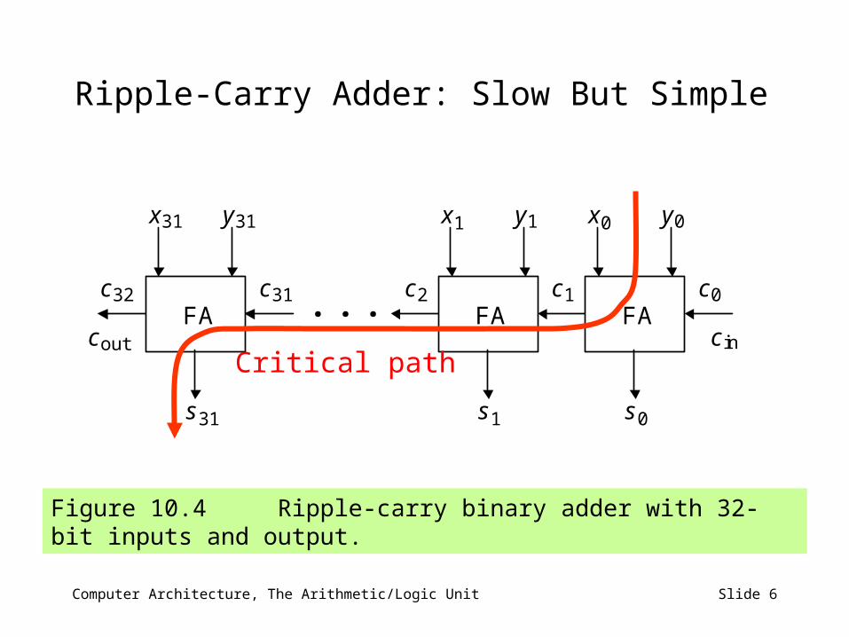
Ripple-Carry Adder: Slow But Simple
Figure 10.4 Ripple-carry binary adder with 32-bit inputs and output.
x
s
y
c c
x
s
y
c
x
s
y
c
c out c in
0 0
0
c 0
1 1
1
1 2
31
31
31
31
FA FA FA 32 . . .
Critical path

Computer Architecture, The Arithmetic/Logic Unit Slide 7
10.2 Carry Propagation Networks
Figure 10.5 The main part of an adder is the carry network. The rest is just a set of gates to produce the g and p signals and the sum bits.
Carry network
. . . . . .
x i y i
g p
s
i i
i
c i c i+1
c k 1
c k
c k 2 c 1
c 0
g p 1 1 g p 0 0
g p k 2 k 2 g p i+1 i+1 g p k 1 k 1
c 0 . . . . . .
0 0 0 1 1 0 1 1
annihilated or killed propagated generated (impossible)
Carry is: g i p i
gi = xi yi pi = xi yi

Computer Architecture, The Arithmetic/Logic Unit Slide 8
Ripple-Carry Adder Revisited
Figure 10.6 The carry propagation network of a ripple-carry adder.
. . . c
k 1
c
k c
k 2
c
1
g
p
1
1
g
p
0
0
g
p
k 2
k 2
g
p
k 1
k 1
c
0 c
2
The carry recurrence: ci+1 = gi pi ci
Latency of k-bit adder is roughly 2k gate delays:
1 gate delay for production of p and g signals, plus 2(k – 1) gate delays for carry propagation, plus1 XOR gate delay for generation of the sum bits

Computer Architecture, The Arithmetic/Logic Unit Slide 9
First Carry Speed-Up Method: Carry Skip
Figures 10.7/10.8 A 4-bit section of a ripple-carry network with skip paths and the driving analogy.
c
g
p
4j+1
4j+1
g
p
4j
4j
g
p
4j+2
4j+2
g
p
4j+3
4j+3
c
4j
4j+4
c
4j+3
c
4j+2
c
4j+1
One-way street
Freeway

Computer Architecture, The Arithmetic/Logic Unit Slide 10
10.3 Counting and Incrementation
Figure 10.9 Schematic diagram of an initializable synchronous counter.
D Q
C _ Q
D
c out
c in
Adder
Update
/ k
k /
a (Increment
amount)
Count register k
/
1
0
Data in
k /
k /
IncrInit

Computer Architecture, The Arithmetic/Logic Unit Slide 11
Circuit for Incrementation by 1
Figure 10.10 Carry propagation network and sum logic for an incrementer.
Substantially simpler than an adder
1
0
k 2
k 1
. . . c
k 1
c
k
c
k 2
c
1
x
x
x
x
c
2
1
0
k 2
k 1
s s s s 2 s
Computer Architecture, The Arithmetic/Logic Unit Slide 12
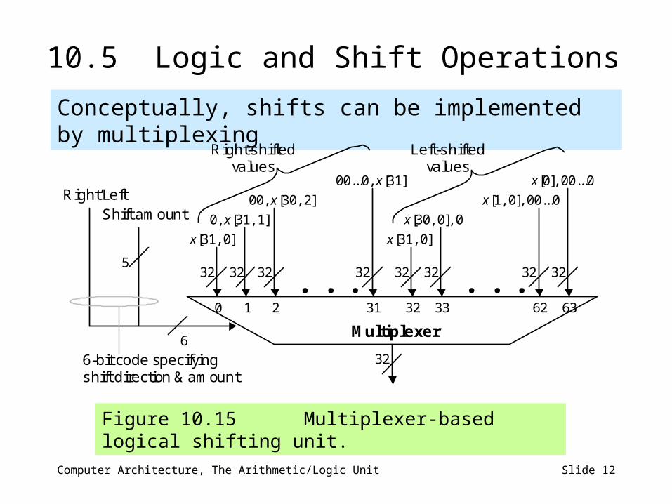
10.5 Logic and Shift Operations
Conceptually, shifts can be implemented by multiplexing
Figure 10.15 Multiplexer-based logical shifting unit.
Multiplexer
0 1 2 31 32 33 62 63
5
6
Right’Left Shift amount 0, x[31, 1]
x[31, 0]
00, x[30, 2]
00...0, x[31]
x[31, 0]
x[30, 0], 0
x[1, 0], 00...0
x[0], 00...0
. . . . . .
32
32 32 32 32 32 32 32 32
6-bit code specifying shift direction & amount
Right-shifted values
Left-shifted values
Computer Architecture, The Arithmetic/Logic Unit Slide 13
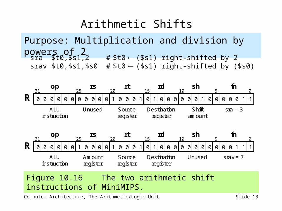
Arithmetic Shifts
Figure 10.16 The two arithmetic shift instructions of MiniMIPS.
Purpose: Multiplication and division by powers of 2
sra $t0,$s1,2 # $t0 ($s1) right-shifted by 2 srav $t0,$s1,$s0 # $t0 ($s1) right-shifted by ($s0)
1 1
1 1
0 0 0
fn
0 0 0 0 0 0 0 0 0 0 0 1 0 0 0 0 1 1 1 0 0 0 0 0 0 0 0
31 25 20 15 0
ALU instruction
Unused Source register
op rs rt
R rd sh
10 5
Destination register
Shift amount
sra = 3
1 0 0 0 0 0 0 0 0 0 0 0 0 0 0 0 0 0 1 1 1 1 0 0 0 0 0 0 0 0
31 25 20 15 0
ALU instruction
Amount register
Source register
op rs rt
R rd sh
10 5 fn
Destination register
Unused srav = 7
Computer Architecture, The Arithmetic/Logic Unit Slide 14
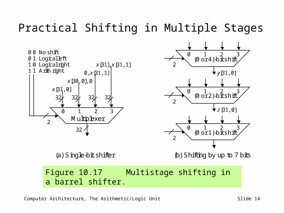
Practical Shifting in Multiple Stages
Figure 10.17 Multistage shifting in a barrel shifter.
2
0, x[31, 1]
x[31, 0]
x[30, 0], 0
32
0 1 2 3
32 32 32 32
0 0 No shift 0 1 Logical left 1 0 Logical right 1 1 Arith right
x[31], x[31, 1]
Multiplexer
2
0 1 2 3 (0 or 4)-bit shift
2
0 1 2 3 (0 or 2)-bit shift
2
0 1 2 3 (0 or 1)-bit shift
(a) Single-bit shifter (b) Shifting by up to 7 bits
y[31, 0]
z[31, 0]

Computer Architecture, The Arithmetic/Logic Unit Slide 15
10.6 Multifunction ALUs
General structure of a simple arithmetic/logic unit.
Logicunit
Arithunit
0
1
Operand 1
Operand 2
Result
Logic fn (AND, OR, . . .)
Arith fn (add, sub, . . .)
Select fn type (logic or arith)

Computer Architecture, The Arithmetic/Logic Unit Slide 16
An ALU for MiniMIPS
Figure 10.19 A multifunction ALU with 8 control signals (2 for function class, 1 arithmetic, 3 shift, 2 logic) specifying the operation.
AddSub
x y
y
x
Adder
c 32
c 0
k /
Shifter
Logic unit
s
Logic function
Amount
5
2
Constant amount
Variable amount
5
5
ConstVar
0
1
0
1
2
3
Function class
2
Shift function
5 LSBs Shifted y
32
32
32
2
c 31
32-input NOR
Ovfl Zero
32
32
MSB
ALU
y
x
s
Shorthand symbol for ALU
Ovfl Zero
Func
Control
0 or 1
AND 00 OR 01
XOR 10 NOR 11
00 Shift 01 Set less 10 Arithmetic 11 Logic
00 No shift 01 Logical left 10 Logical right 11 Arith right