Embed Size (px)
Citation preview
© 2003 香港中文大學,電子工程學系 (Prof. H.K.Tsang) ITM 1010 計算機與通訊技術 1
ITM 1010ITM 1010Computer and Communication TechnologiesComputer and Communication Technologies
Lecture #14Lecture #14Part IIPart II Introduction to Communication Technologies:Introduction to Communication Technologies:
Digital Signals:Digital Signals:Digital modulation, channel sharingDigital modulation, channel sharing

ITM 1010 計算機與通訊技術 2© 2003 香港中文大學 電子工程學系
Nyquist rate and Shannon’s channel capacity
! Nyquist sampling rate: An analog signal with a finite bandwidthw may be completely specified by sampling at a rate 2w.– Sampling at less than 2w will produce aliasing errors
! Shannon’s Channel Capacity Theorem: The maximum rate at which information may be sent in a channel which has white Gaussian noise is
( )NPBC /1log2 += bits per second

ITM 1010 計算機與通訊技術 3© 2003 香港中文大學 電子工程學系
Digital Modulation
! After a base band signal of bandwidth B is sampled at a rate of at least 2B, the resulting 2B samples may be sent by many different techniques. We shall only consider:
1. Pulse Amplitude modulation (PAM): uses analog pulses whose amplitudes are proportional to the amplitudes of the samples
2. Pulse coded modulation (PCM): each sample is converted to a number (analog- to-digital converter) which is sent in a digital code (e.g. binary). This is the most common form of digital transmission.

ITM 1010 計算機與通訊技術 4© 2003 香港中文大學 電子工程學系
Pulse Amplitude Modulation
-1
0
1
-2 -1 0 1 2
Sampling
sampled signal
-1
-0.5
0
0.5
1
-2 -1 0 1 2
Original continuous signal
! Pulse amplitude modulation sends pulses of varying amplitudes which represent the sampled signal amplitude
! Disadvantage of PAM: wider bandwidth is needed in communicationschannel than for analog signal (because of narrow pulses)
! Noise performance poor (sending the continuous signal directly is better)! PAM is mainly used as first step in generating pulse code modulation
ITM 1010 計算機與通訊技術 5© 2003 香港中文大學 電子工程學系
Pulse Code Modulation (PCM)
sampler Quantizer Encoderm(t) PAM PCM
Base band signal
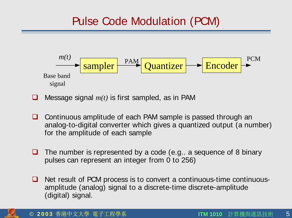
! Message signal m(t) is first sampled, as in PAM
! Continuous amplitude of each PAM sample is passed through an analog-to-digital converter which gives a quantized output (a number) for the amplitude of each sample
! The number is represented by a code (e.g.. a sequence of 8 binary pulses can represent an integer from 0 to 256)
! Net result of PCM process is to convert a continuous-time continuous-amplitude (analog) signal to a discrete-time discrete-amplitude (digital) signal.

ITM 1010 計算機與通訊技術 6© 2003 香港中文大學 電子工程學系
Quantization errors
0
100
110 Quantization of two pulsesin a 8 level quantizer
Quantization interval
! Actual PAM pulse may have an amplitude which lies between two adjacent discrete levels in the quantizer
! Quantization error is the difference between the original PAM sample amplitude and the number produced by the quantizer
! If there are q different levels in the quantizer, n=log2q binary digits are needed to digitize each sample
! Quantization error may be reduced by increasing the number of levels used. This will increase the number of binary digits needed (trade-off between bandwidth and error).

ITM 1010 計算機與通訊技術 7© 2003 香港中文大學 電子工程學系
Quantization noise
! Quantization will degrade the signal to noise ratio of the sampled data train because of there is an inherent uncertainty (quantization interval) in the amplitude of the original signal.
Suppose maximum signal voltage is V and n bits are used for each sample
nV
22 =Quantization interval n
V2
=Maximum quantization error
nV
2
2
2 =Quantization noise power
n
nVV 2
2
2
22
2
==Best signal to noise ratio
( ) ]dB[02.62log10 [dB] / 210 nNS n ==
! For any given sample the signal to noise ratio can be much lower if the sample has a smaller voltage than the maximum signal voltage.

ITM 1010 計算機與通訊技術 8© 2003 香港中文大學 電子工程學系
Bitrate needed for PCM
! Suppose the bandwidth of the original source signal m(t) is w− The minimum sampling rate is 2w (Nyquist rate)− If the quantizer produces n bits per sample the minimum
bitrate B is nw2B = bits/second
! The frequency spectrum of the PCM signal depends on the form of coding used to represent the digital data
! In general, for reasonable values of n with binary coding, PCM requires a channel with a much larger bandwidth than is needed for the original analog signal. E.g. a telephone voice circuit needs 64kbits/s line capacity (compare to the 4KHz bandwidth of the base band signal)

ITM 1010 計算機與通訊技術 9© 2003 香港中文大學 電子工程學系
Advantages of PCM
! Regeneration: Digital signal may be detected, regenerated as a clean noise-free signal and re-sent thus allowing the data to be transmitted without error over long distances and allowing the original signal to be reconstructed without distortion irrespective of the distance sent
! Multiplexing: Different data streams (e.g. different telephonelines) can be easily combined together to form a combined data stream that may be sent over a single communications channel
! Compression: Digitisation of the analog signal allows the use of advanced coding techniques which compress data to its essential information content, thus making efficient use of limited bandwidth

ITM 1010 計算機與通訊技術 10© 2003 香港中文大學 電子工程學系
Line Codes
! Line codes represent binary data in electrical transmission ! Some common line codes are:
0 0 0 0 0 0 0 01 1 1 1 1 1 1Non return-to-zero (NRZ)
- problem with dc level in signal
Bipolar non return-to-zero (NRZ)- problem with large amount of power near 0 Hz
Return-to-zero (RZ)- allows easy clock recovery in receiver
Manchester code (split phase code)- advantages of having no dc component and insignificant low frequency power in spectrum

ITM 1010 計算機與通訊技術 11© 2003 香港中文大學 電子工程學系
PCM Communications System
! Initial low pass filter is to limit bandwidth of baseband to remove high frequency components and prevent aliasing
! Reconstruction filter recovers the baseband spectrum from the repetitive spectrum produced by sampling
G(f)
f
Spectrum of sampled signal g(t)
0 w-w-2fs - fs-w -fs+w-fs fs 2fs
sampler Quantizer Encoder
Low pass filter
m(t) PCMPAM
Base band signal
Transmission line
noise
PAMReconstruction filter
decoderm(t)
ITM 1010 計算機與通訊技術 12© 2003 香港中文大學 電子工程學系
Intersymbol Interference (ISI)
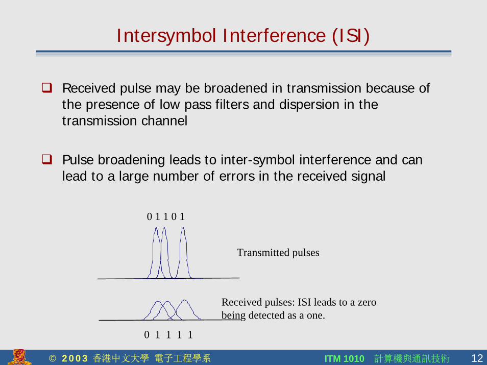
! Received pulse may be broadened in transmission because of the presence of low pass filters and dispersion in the transmission channel
! Pulse broadening leads to inter-symbol interference and can lead to a large number of errors in the received signal
0 1 1 0 1
Transmitted pulses
0 1 1 1 1
Received pulses: ISI leads to a zero being detected as a one.

ITM 1010 計算機與通訊技術 13© 2003 香港中文大學 電子工程學系
Keying
! Basic modulation techniques for sending digital data on a carrier wave include:
0 0 0 0 0 0 0 01 1 1 1 1 1 1 Data stream
Amplitude shift keying
Phase shift keying
Frequency shift keying

ITM 1010 計算機與通訊技術 14© 2003 香港中文大學 電子工程學系
Summary
! Signals may be sent digitally by pulse code modulation" PCM allows signals to be regenerated" PCM generally occupies a wider bandwidth" Allows data compression and multiplexing
( ) ]dB[02.62log10 [dB] / 210 nNS n ==Best possible signal to noise ratio:

© 2003 香港中文大學,電子工程學系 (Prof. H.K.Tsang) ITM 1010 計算機與通訊技術 15
Channel Sharing
How can many users all use the same communications channel?
ITM 1010 計算機與通訊技術 16© 2003 香港中文大學 電子工程學系
Multiplexing and Multiple Access
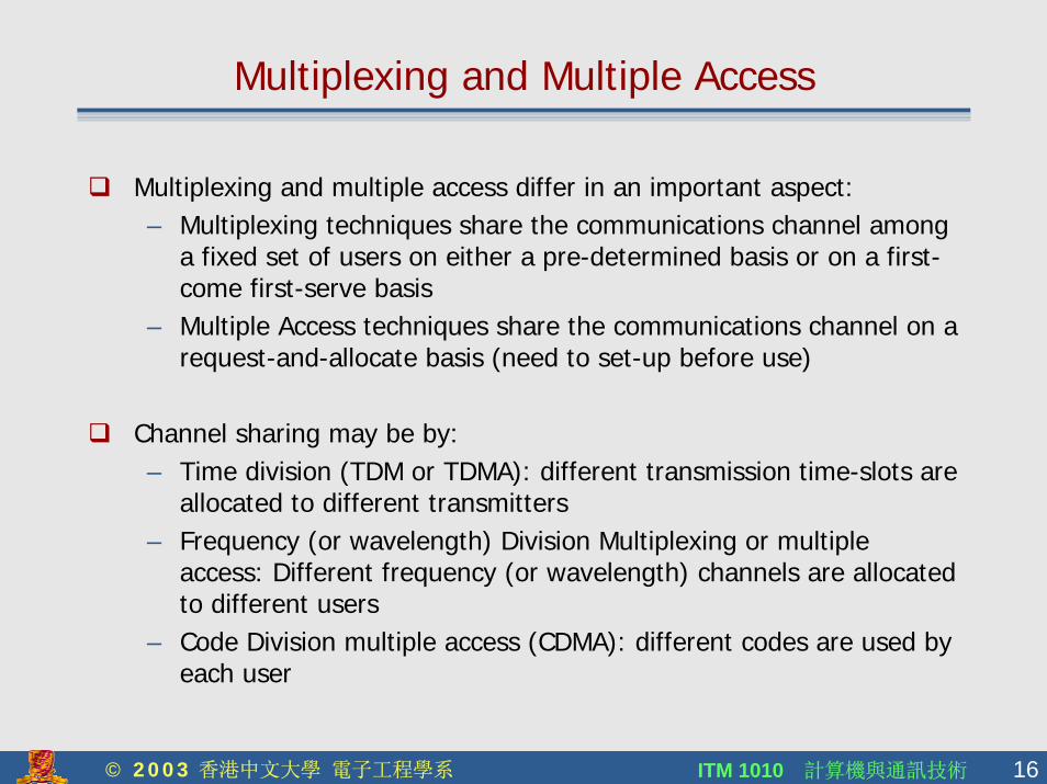
! Multiplexing and multiple access differ in an important aspect:– Multiplexing techniques share the communications channel among
a fixed set of users on either a pre-determined basis or on a first-come first-serve basis
– Multiple Access techniques share the communications channel on arequest-and-allocate basis (need to set-up before use)
! Channel sharing may be by:– Time division (TDM or TDMA): different transmission time-slots are
allocated to different transmitters– Frequency (or wavelength) Division Multiplexing or multiple
access: Different frequency (or wavelength) channels are allocated to different users
– Code Division multiple access (CDMA): different codes are used by each user
ITM 1010 計算機與通訊技術 17© 2003 香港中文大學 電子工程學系
Time Division Multiplexing (TDM)
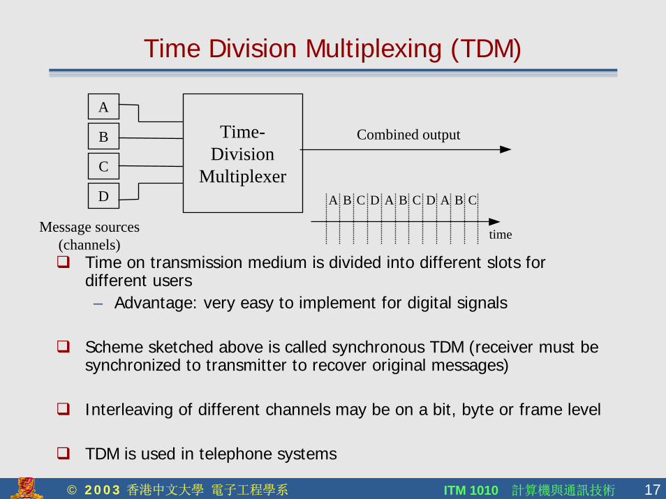
! Time on transmission medium is divided into different slots for different users– Advantage: very easy to implement for digital signals
! Scheme sketched above is called synchronous TDM (receiver must be synchronized to transmitter to recover original messages)
! Interleaving of different channels may be on a bit, byte or frame level
! TDM is used in telephone systems
D
A
B
C
Message sources(channels)
Time-Division
Multiplexer
Combined output
time
A B C D A B C A BD C

ITM 1010 計算機與通訊技術 18© 2003 香港中文大學 電子工程學系
Synchronous and Statistical TDM
! Synchronous TDM– Time slots are pre-allocated for each different user– Advantages: simplicity, little overhead, instant access – Disadvantage: potentially very wasteful of bandwidth e.g.
some timeslots may not be needed all the time by a particular channel so the timeslots may go unused despite other channels needing to use the resource
! Statistical TDM– Instead of pre-allocated time-slots being assigned to
different channels, the multiplexer assigns the available time slots to different channels dynamically
– To identify the data in each time slot, a channel id must also be transmitted
– Main advantage over synchronous TDM is more efficient usage of bandwidth.

ITM 1010 計算機與通訊技術 19© 2003 香港中文大學 電子工程學系
Statistical Multiplexing
Statistical Time-divisionMultiplexer
Combined output
time
C B D A D A A DC B
B
C
D
A
! Statistical multiplexing is suited to systems with bursty data traffic in each channel rather than a constant data rate.
! Input data packets must be stored in buffers when no time slots are free for them to go out on
! Internet routers are an example of a statistical multiplexer
ITM 1010 計算機與通訊技術 20© 2003 香港中文大學 電子工程學系
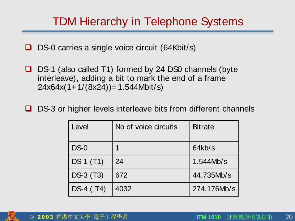
TDM Hierarchy in Telephone Systems
! DS-0 carries a single voice circuit (64Kbit/s)
! DS-1 (also called T1) formed by 24 DS0 channels (byte interleave), adding a bit to mark the end of a frame 24x64x(1+1/(8x24))=1.544Mbit/s)
! DS-3 or higher levels interleave bits from different channels
274.176Mb/s4032DS-4 ( T4)
44.735Mb/s672DS-3 (T3)
1.544Mb/s24DS-1 (T1)
64kb/s1DS-0
BitrateNo of voice circuitsLevel
ITM 1010 計算機與通訊技術 21© 2003 香港中文大學 電子工程學系
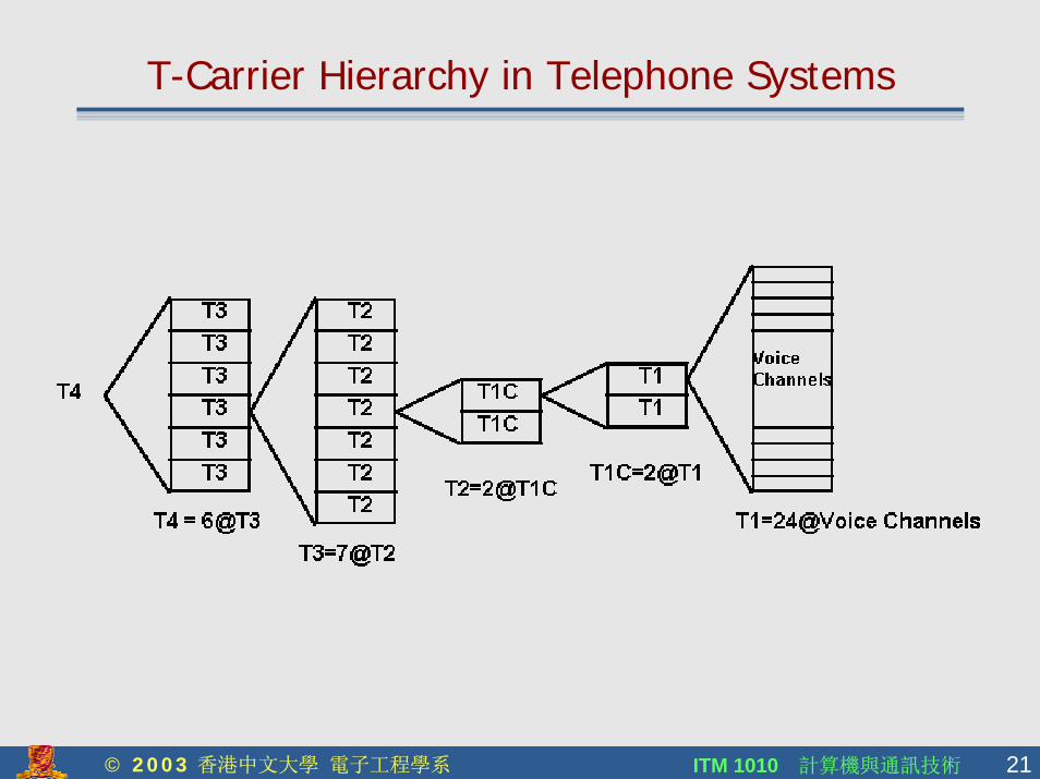
T-Carrier Hierarchy in Telephone Systems

ITM 1010 計算機與通訊技術 22© 2003 香港中文大學 電子工程學系
SONET
! Many DS-3 channels may be sent over the Synchronous Optical Network (SONET), which has been adopted as an ITU standard
! Basic bit-rate in SONET is 51.84Mb/s for the STS-1 level (synchronous transport signal), which can carry a DS-3 or equivalent signal
! Higher SONET levels operate at a multiple of the basic bit-rate (e.g. STS-3 operates at 3x51.84=155.52Mb/s)
! SONET levels commonly used include STS-N where N can be 3, 12, 24, 48, 96 and 192 (192x51.84=9953Mb/s)
! Alternative name is the OC-N (Optical Carrier), where N is the same as above (ie OC-1 is the same as STS-1)
ITM 1010 計算機與通訊技術 23© 2003 香港中文大學 電子工程學系
Frequency Division Multiplexing
! Frequency is divided into channels which may be used independently for different sources
! Employed in radio communications systems and (older) telephone systems
! Also used in fiber optic communication systems (Wavelength division multiplexing)
! FM stereo broadcasts are an example of FDM– Monaural (Left + Right) audio channel baseband is
transmitted with a difference signal (left-right) that is shifted by 38KHz (DSB-SC [Double Sideband Suppressed Carrier] is used to transmit the difference signal)

ITM 1010 計算機與通訊技術 24© 2003 香港中文大學 電子工程學系
FDM in Telephone Systems
! Older telephone systems employed FDM to transmit many different voice channels over a single telephone line
# Standard: Twelve 4KHz channels forms a group (60-108KHz)– Five groups (60 voice channels) form a supergroup– Five supergoups form a mastergroup (300 voice channels)
f
f
f
Ch.1
Ch.2
Ch.3
Ch.4
V(f)
FDM spectrum
0
Ch.2 Ch.3 Ch.4Ch.1
f
f

ITM 1010 計算機與通訊技術 25© 2003 香港中文大學 電子工程學系
Wavelength Division Multiplexing
! Wavelength λ is related to frequency f and the speed of light cby
! DWDM (dense wavelength division multiplexing) is used in optical fiber communications to multiply the data carrying capacity of an optical fiber
! ITU defines a standard set of wavelengths at 50GHz, 100GHz or 200GHz frequency spacing (ITU grid) for DWDM
! DWDM uses different optical wavelengths to carry different channels. Systems using 40 different wavelengths each modulated at 10Gbit/s are in use today.
λfc =

ITM 1010 計算機與通訊技術 26© 2003 香港中文大學 電子工程學系
Multiple Access
! Important distinction from multiplexing: must set-up a channel before it can be used
! Multiple access techniques include:– Time division multiple access (TDMA is used in mobile
phone networks)– Frequency or wavelength division multiple access (WDMA)– Code division multiple access (CDMA, also used in mobile
phone networks)
! Multiple access techniques may be combined (eg FD/TDMA)
! Multiple access is used in computer local area networks
ITM 1010 計算機與通訊技術 27© 2003 香港中文大學 電子工程學系
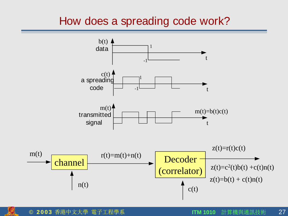
How does a spreading code work?
t
b(t)data 1
-1
t
c(t)a spreading
code
1
-1
t
m(t)transmitted
signal
m(t)=b(t)c(t)
Decoder(correlator)
c(t)
z(t)=r(t)c(t)
z(t)=c2(t)b(t) +c(t)n(t)
z(t)=b(t) + c(t)n(t)
channelm(t)
n(t)
r(t)=m(t)+n(t)

ITM 1010 計算機與通訊技術 28© 2003 香港中文大學 電子工程學系
Code Division Multiple Access (CDMA)
! CDMA does not require the frequency band allocation as in FDMA nor the time synchronization as in TDMA
! All users share the same channel and may transmit at the same time and in the same frequency band. CDMA is typically used in wireless networks (eg digital mobile phone networks)
! Messages from each user are distinguishable because each user has his own “spreading code”. The cross-correlation between two different spreading-codes is zero.
! The receiver must use a correlator that is matched to a particular code to distinguish an individual message: other messages will appear as noise which averages out to zero.

ITM 1010 計算機與通訊技術 29© 2003 香港中文大學 電子工程學系
Summary
! Sharing of a channel may be by multiplexing or multiple access– Multiplexing: users can transmit data in their own dedicated
channel (frequency channel in FDM, time slot in TDM)– Multiple Access: Users must first request and set up the
channel before transmitting data
! Telephone systems organized in a TDM hierarchy– Lower levels (mobile phones) may use CDMA or TDMA– Higher levels in TDM hierarchy use optical fibers and may
also use DWDM