Embed Size (px)
Citation preview

NREL is a national laboratory of the U.S. Department of Energy, Office of Energy Efficiency and Renewable Energy, operated by the Alliance for Sustainable Energy, LLC.NREL is a national laboratory of the U.S. Department of Energy, Office of Energy Efficiency and Renewable Energy, operated by the Alliance for Sustainable Energy, LLC.
Computer‐Aided Engineering of Batteries for Designing Better Li‐Ion Batteries
Ahmad Pesaran, Ph.D.Gi‐Heon Kim, Ph.D.Kandler Smith, Ph.D.Kyu‐Jin Lee, Ph.D. Shriram Santhanagopalan, Ph.D.
Advanced Automotive Battery ConferenceBattery Modeling Software and Applications WorkshopOrlando, Florida, February 6, 2012
NREL/PR‐5400‐53777
Funded by Energy Storage R&D Dave Howell and Brian CunninghamVehicle Technologies ProgramU.S. Department of Energy
2
Energy Storage R&D Program• DOE ES Charter: Advance the development of batteries and
electrochemical energy storage devices to enable a large market penetration of hybrid and electric vehicles.
• DOE ES Focus: Increase performance at lower cost while meeting weight, volume, and safety targets.
• NREL ES Objective: Support DOE and industry to achieve energy storage targets through research and development, testing, analysis, design, and modeling.
DOE’s Energy Storage R&D Portfolio from AMR‐2011
……….Modeling and Simulation across all areas…………………………

3
Modeling and Design Tools
• Simulation and computer‐aided engineering (CAE) tools are widely used to speed up the research and development cycle and reduce the number of build‐and‐break steps.
• Use of CAE tools has enabled the automakers to reduce product development cost and time while improving the safety, comfort, and durability of many components and vehicles.
• There is a need to have several user‐friendly, 3D, fully‐integrated CAE software tools available for the battery community across many scales.
Most models are wrong, but some are useful…..anonymous

4
The Current State of Battery Modeling
• There are a number of battery models in academia, national labs, and industry, but they eithero Include relevant physics details, but mostly neglect engineering complexities, or
o Include relevant macroscopic geometry and system conditions in 3D, but use too many simplifications in fundamental physics.
• There are a number of custom battery codes available; however, they require expert users.
• The Battery Design Studio software suite has been in the forefront of battery simulations and now is being integrated into CD‐adapco’s CAE environment.
• Validation of data is the key to building confidence.

5
The Current State of Battery Modeling
• With DOE funding, national laboratories, industry, and universities have developed many models for simulating lithium‐ion battery (LIB)o cost,o life,o performance (electro‐thermal, electrochemical), ando abuse reactions.
• So far, these models have not been fully integrated into 3D CAD for design of battery packs and linked with ease, especially for engineering purposes.
• Realizing the need, DOE has initiated the CAEBAT project to bring together these battery models to develop suites of battery CAE tools.
6
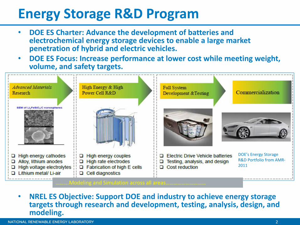
DOE’s CAEBAT Program• Objective: Incorporate existing and new models into software tools for
design of cells and packs.• Goal: Shorten development and design cycles and optimize batteries for
improved performance and safety, long life, and low cost.

7
NREL’s Role in the CAEBAT Project1. As project coordinator, NREL supports DOE to achieve the
CAEBAT objectives:o Provide input/support to DOE for the CAEBAT project plano Coordinate activities among national laboratorieso Support industry and universities through competitively‐placed
subcontracts– 50%‐50% cost sharing with three teams– Work started in June 2011 to develop CAE tools
2. Enhance and further develop existing electrochemical, thermal, abuse reaction, and internal short circuit models for use by industry and CAEBAT participants.
8
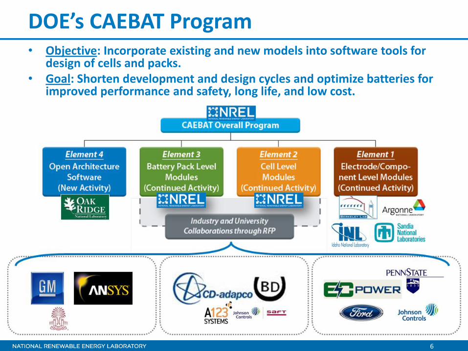
Battery Performance, Durability and Safety
Multi‐physics Interactions Across VariedLength Scales

9
Porous Electrode Model – Commonly Used
Charge Conservation
Ues
qTktTcp
• Pioneered by John Newman’s group at the University of Berkeley (Doyle, Fuller, and Newman 1993)
• Captures lithium diffusion dynamics and charge transfer kinetics
• Predicts current/voltage response of a battery• Provides design guide for thermodynamics, kinetics,
and transport across electrodes
eeeffDee
effss
effes
Li cTUTUjq
ln
Charge Transfer Kinetics at Reaction Sites
Species Conservation
Energy Conservation • Difficult to apply in large‐format batteries where heat and electron current transport critically affect the battery responses
r

10
NREL’s MSMD Model Framework
• Introduce multiple computational domains for corresponding length scale physics
• Decouple LIB geometries into separate computation domains
• Couple physics using the predefined inter‐domain information exchange
• Selectively resolve higher spatial resolution for smaller characteristic length scale physics
• Achieve high computational efficiency• Provide flexible & expandable modularized
framework
Kim et al., “Multi-Domain Modeling of Lithium-Ion Batteries Encompassing Multi-Physics in Varied Length Scales,” J. of Electrochemistry, 2011, Vol. 158, No. 8, pp. A955–A969
Through the multi‐year effort supported by DOE, NREL has developed a modeling framework for predictive computer simulation of LIBs known as the Multi‐Scale Multi‐Dimensional (MSMD)model that addresses the interplay among the physics in varied scales.
11
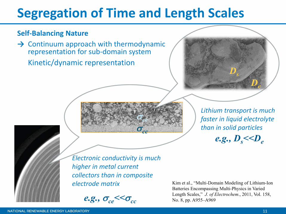
Segregation of Time and Length ScalesSelf‐Balancing Nature→ Continuum approach with thermodynamic
representation for sub‐domain systemKinetic/dynamic representation
cc
ce
Electronic conductivity is much higher in metal current collectors than in composite electrode matrix
e.g., ce<<cc
DsDe
Lithium transport is much faster in liquid electrolyte than in solid particles
e.g., Ds<<De
Kim et al., “Multi-Domain Modeling of Lithium-Ion Batteries Encompassing Multi-Physics in Varied Length Scales,” J. of Electrochem., 2011, Vol. 158, No. 8, pp. A955–A969

12
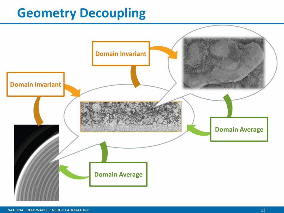
Geometry Decoupling
Domain Invariant
Domain Average
13
Geometry Decoupling
Domain Invariant
Domain Invariant
Domain Average
Domain Average

14
MSMD Protocol for Transferring Information

15
MSMD Protocol for Transferring Information

16
MSMD Protocol for Transferring Information

17
Hierarchical Architecture of MSMD • Modularized flexible framework for multi‐scale
multi‐physics battery modeling• Expandable development platform providing “pre‐
defined but expandable communication protocol”
• Charge transfer kinetics• Li diffusion dynamics in electrode particulates and in electrolyte• Charge balance• Energy conservation• …
Kim et al., “Multi-Domain Modeling of Lithium-Ion Batteries Encompassing Multi-Physics in Varied Length Scales,” J. of Electrochemistry, 2011, Vol. 158, No. 8, pp. A955–A969
Particle Domain• Charge transfer kinetics• Li transport in active particles• …
Electrode Domain• Charge balance in solid composite electrode
matrix• Charge balance in liquid pore channels • Li transport in electrolyte• …
Cell Domain• Energy conservation• Charge conservation in current collectors• …

18
Modularized Development
Electrode Domain Submodel Development
Solution Model/Method Development
Particle Domain Submodel Development
Solution Model/Method Development
Cell Domain Submodel Development
Solution Model/Method Development
Modularized hierarchical architecture of the MSMD model allows independent development of submodels for physics captured in each domain.
The modularized framework facilitates collaboration with external expertise.

19
Cell Domain Models• SPPC (Single Potential‐Pair Continuum) model:
applicable to stack prismatic cells, tab‐less wound cylindrical/(prismatic) cells:
• MPPC (Multi Potential‐Pair Continuum) model: applicable toalternating stackedprismatic cells:
• WPPC (Wound Potential‐Pair Continuum) model: applicable to spirallywound cylindrical/(prismatic) cells:
• Lumped model: applicable to small cells
NREL’s Cell‐Domain Models: Orthotropic Continuum Model
Discussed in this presentation
Wound cell with continuous tab

20
Wound cell with continuous tab
SPPC: Single Potential‐Pair Continuum
Arbitrary finite volume of cell composite
Cell Composite Orthotropic Continuum Model
ijptj
tiptij keekkk
tj
tiijij
eff ee
tj
tiijij
eff ee

21
MSMD Application to Prediction of Large Stacked Prismatic Cell Behavior
• SVM(state variable method)
• FV‐LSMfinite volume – linear superposition methods
• SVM
• 1D spherical particle model
Submodel in the Particle Domain
Submodel in the Electrode Domain
Submodel in the Cell Domain
Submodel Choice Solution Method
• 1D porous electrode model
• 3D Single Potential‐Pair Continuum Model (SPPC)

22
Electric Current Transport4C discharge / Single‐side cooling

23
Electric Current Transport
0 110 135 215-100
-80
-60
-40
-20
0
e [
mV
]
x [m]
1C
2C3C
4C
4C discharge / Single‐side cooling bottomcooled top

24
Non‐Uniform Utilization
Mid‐size sedan PHEV10 US06
Kim et al., “Multi-Domain Modeling of Lithium-Ion Batteries Encompassing Multi-Physics in Varied Length Scales,” J. of Electrochem., 2011, Vol. 158, No. 8, pp. A955–A969
Tab size

25
Wound Cells• A pair of wide current collectors• Two electrode pairs• Cylindrical or prismatic cells
Stacking : Forming the first pair between inner electrodes
Winding : Forming the second pair between outer electrodes
Current collector
Current collectorSeparator
electrode
electrodePairing Inner Electrodes
Separator
electrode
electrode
Pairing Outer Electrodes

26
WPPC (Wound Potential‐Pair Continuum)
SeparatorSeparator
Unit stratum/finite cell volume
Applicable to flat wound prismatic cells
27
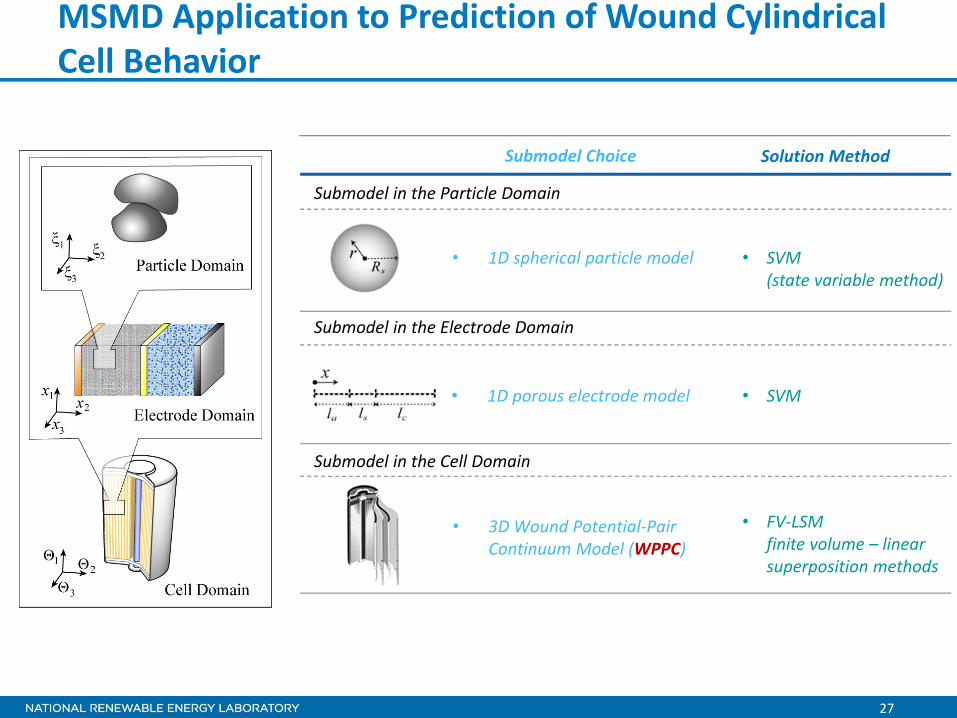
MSMD Application to Prediction of Wound Cylindrical Cell Behavior
• SVM(state variable method)
• FV‐LSMfinite volume – linear superposition methods
• SVM
• 1D spherical particle model
Submodel in the Particle Domain
Submodel in the Electrode Domain
Submodel in the Cell Domain
Submodel Choice Solution Method
• 1D porous electrode model
• 3D Wound Potential‐Pair Continuum Model (WPPC)

28
Kinetics ResponseImpact of electrical current transport design
Kyu-Jin Lee, et al., April 2011
Continuous-tabs (CT) cell
29
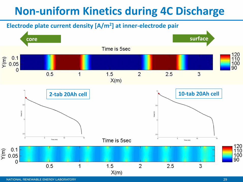
Non‐uniform Kinetics during 4C DischargeElectrode plate current density [A/m2] at inner‐electrode pair
2‐tab 20Ah cell 10‐tab 20Ah cell
surfacecore

30
Thermal Response
Temperature imbalance at 4C discharge
Continuous-tabs (CT) cell
Kyu-Jin Lee, et al., April 2011
Impact of electrical current transport design

31
Thermal Evolution during 4C Discharge2‐Tab Design
surfacecore
32
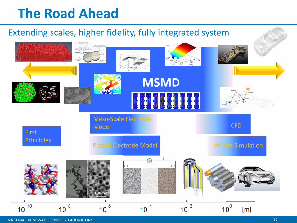
The Road Ahead
FirstPrinciples
Meso‐Scale Electrode Model
Porous Electrode Model
MSMD
CFD
Vehicle Simulation
Extending scales, higher fidelity, fully integrated system

33
Acknowledgments
• Support Provided by the DOE Vehicle Technologies Programo Dave Howell, Hybrid and Electric Systems Team Leado Brian Cunningham, Energy Storage Technology Manager
• Feedback from CAEBAT Subcontract Technical Leadso Taeyoung Han (General Motors)o Steve Hartridge (CD‐adapco)o Christian Shaffer (EC Power)
• NREL Support for CAEBAT Implementation o Terry Penneyo Barbara Goodmano Michael Spragueo Kathy Roqueo John Enoch

![HPC Computer Aided Engineering @ · PDF fileComputer Aided Engineering [From Wikipedia, the free encyclopedia] Computer-aided engineering (CAE) is the broad usage of computer software](https://img.dokumen.tips/doc/110x75/5a7176547f8b9ab6538cc8f4/hpc-computer-aided-engineering-cinecawwwtrainingprace-rieuuploadstxpracetmocaeintropdfpdf.jpg)