Embed Size (px)
Citation preview
Institut für Mechanik
Computer-aided destruction of complex structures by blasting
Steffen Mattern, Gunther Blankenhorn, Karl Schweizerhof
Universität Karlsruhe, Institut für Mechanik
Institut für Mechanik Kaiserstr. 12, Geb. 20.30
76128 Karlsruhe Tel.: +49 (0) 721/ 608-2071 Fax: +49 (0) 721/ 608-7990
E-Mail: [email protected] www.ifm.uni-karlsruhe.de
Computer-aided destruction of complex
structures by blasting
Steffen Mattern Gunther BlankenhornKarl Schweizerhof
1 Introduction
The controlled destruction of buildings at the end of their average life cyclehas become more and more important during the last years. An economicway of dismounting is a demolition of a partially dismountable structure withexplosives. Within this method, several structural elements of a building’sload carrying system are removed by explosives to initiate a particular col-lapse. The strategy of blasting, i.e. the selection of the structural elements,which are destroyed by the explosives, is performed by engineers with specialknowledge in this field of demolition. However the prediction of the col-lapse supported by fairly simple analysis models requires a great amount ofexperience and is very error sensitive if the building construction is complex.
In this contribution a ’complex construction’ means a construction in-cluding several hundred structural elements like beams, plates, columns, etc.for which it is rather difficult to predict the collapse kinematics with simplemechanical tools. In order to develop a suitable strategy of blasting for com-plex structures, a reliable ’a-priori-simulation’ of the collapse of the completestructure is mandatory. The goal of the investigations is to obtain a goodprediction of the collapse mechanism by a numerical simulation of a com-plete real building. The analyses are performed using the Finite ElementMethod (FEM) combined with explicit time integration, which has alreadybeen approved as simulation tool for structural analyses involving impactand contact. Such rather costly simulations – costly with respect to thecomputational effort – are meant to support the development of a reliableand efficient simulation tool for demolition by blasting that will be devel-oped throughout the research project FOR500 (funded by DFG). CompleteFE-simulations of the failure process of a complex building require enormouscomputational resources and parallelization of such problems is inevitable.
1
Within the contribution, first some general informations about the stateof the art in building demolition is given. Then the methods used for thenumerical analyses are discussed and the simulated reference models are pre-sented. All computations and parametrical studies which were necessary todevelop and improve the models were performed on the HP XC6000-Clusterof the University of Karlsruhe [2].
2 Building demolition - State of the art
Compared to methods such as destruction with dredgers or systematic de-construction, blasting demolition definitely won recognition on braking downbrickwork, reinforced concrete and steel constructions because of economicand technical reasons. Demolition by blasting, together with special possi-bilities of local weakening (e.g. cutting of reinforcement, deconstruction ofsupporting parts with special machines), allows the teardown of a buildingat a moderate time of preparation, proper planning of the blasting strat-egy and accurate positioning of the explosive charge presumed. Annoyanceof residents is kept to a temporal minimum, business as usual and trafficaround the object are disturbed only for a short while. The effort for nec-essary safety arrangements is considerably reduced compared to mechanicaldeconstruction, because the zone of danger can be evacuated during the col-lapse. For those reasons, popularity of blasting demolition raised in the lastfew years, especially in inner-city areas. General information about planningand accomplishment of a building demolition is given e.g. in [9].
Nevertheless, blasting demolition can be very dangerous, used for complexand non-trivial buildings, for which precise information about the construc-tion details and the used materials is sometimes rare or even not availableat all. The consequences can be recognized, when e.g. dynamic effects ofthe structure have not been considered correctly. This sometimes leads touncontrolled collapses, which cause high damage. Dangerous situations canalso arise, if a planned collapse is not completed and the remaining partsof the building have to be removed manually. In such situations expensiveprocedures are necessary to finish the demolition. Currently only severalrudimental mechanical tools are used to predict the collapse, but in orderto avoid accidents and the corresponding high costs, it is necessary to re-alize a reliable simulation of the complete collaps, which requires modernmechanical methods.
2
3 Numerical analysis
3.1 Basic idea
The safe execution of the destruction of a building using controlled explo-sives requires detailed and reliable knowledge about the kinematics of thecollapse with a special blasting strategy. In order to realize collapse simula-tions e.g. with different locations of the explosive loads, the Finite ElementMethod with explicit time integration is used within this project. Applyingthis method makes it possible to analyse the entire building from the time ofblasting till the end of the breakdown. The knowledge won by those simu-lations is used to support and validate an alternative method based on rigidbody models which requires far less computational effort. Such an efficientway of simulation allows the concerning of uncertainties e.g. with fuzzy al-gorithms [10], which require many deterministic solutions of one structure.The final goal here is to extract such models of reduced size based on certainmodeling or decision rules by rigidizing parts of the structure during the sim-ulation [1]. In order to gain proper insight and in particular, for validationpurposes many analyses of different structures, i.e. extensive parametricalstudies are necessary.
3.2 Numerical algorithms
First the numerical algorithms, used to solve this highly non-linear problem,have to be chosen. The problem is driven by finite deformations, finite rota-tions, non linear material behavior and multiple contact possibilities. On theother hand, the spatial discretization must be done by continuum elementsto catch the contact surfaces in a better way, in comparison to structuralelements. This leads to a large number of elements. Considering all require-ments, a combination of FE-analysis with explicit time integration [3, 8, 5] ischosen. The small time step size, which is needed for numerical robustness,is compensated by highly efficient element formulations and the highly de-veloped capabilities for dividing the problem to several computation units.Also the contact possibilities have to be taken into account which naturallyreduce the possible time step size. As a conclusion the disadvantage of asmall time step size in explicit methods – here the central difference scheme[11]– is abolished by its efficient implementation and parallelization [6].
3
4 Reference Models
4.1 General Information
In order to cary out the analyses, in this project the commercial FE-programLS-Dyna is used, which uses a central difference method for the time inte-gration [7, 6]. The code is highly parallelized and perfectly suited to run onclusters such as the HP XC6000. For discretization of the structural parts,one-point under-integrated hexahedral elements are chosen, which performexcellently without showing any locking. However a stabilization against un-physical element kinematics, the hourglass modes, is required. The chosenhourglass stabilization – Belytschko-Bindemann assumed strain co-rotationalstiffness form, which performs extremely well – is described in detail in [4].
For all concrete parts, a piecewise linear plasticity material model is used.The parameters, necessary for concrete like behavior of this on purpose sim-plified material law were obtained by calibrating with rather simple exper-imental examples. However, though the material model does not allow de-tailed modification concerning e.g. reinforcement, the reached approximationfor the investigated mass dominated problems was fairly good. The possi-bility of element failure, which is necessary to simulate the appearance oflocal zones of accumulated damage (hinges) during the collapse event is alsoimplemented in the material model. E.g. every time an element reaches aspecific plastic strain, it is removed from the computation. Especially thismechanism helps to support the development of rigid body models as men-tioned in Section 3.1. Concerning accuracy, it is acceptable to use the samematerial model for each simulation since the spare available documentationsof the objects contain little information about the used concrete and steel.Investigations with more detailed material models on local submodels of thesimulated structure are carried out in another subproject involved in theResearch Unit 500 [1].
Every time contact appears during the collapse event, the kinematicalconfiguration of the simulated structure changes abruptly. Hence correct de-termination of contact within parts of the building and between building andground is also very important to obtain realistic collapse behavior of a model.For this reason fast automatic contact search algorithms are implemented inLS-Dyna. Though these algorithms show very good performance concerningaccuracy and computation time, the search for contact requires a consider-able amount of CPU-time of the whole simulation as each surface segmentof the FE-mesh has to be considered. The chosen contact formulation is apenalty based node-to-segment algorithm for building to baseplate contactand a segment-to-segment algorithm between the building parts in all inves-
4
tigations. The base plate was modeled with four-node shell elements whichwere assumed to be rigid in each of the three presented models representingthe contact segments for the base plate.
4.2 Storehouse in Weida/ Thuringen
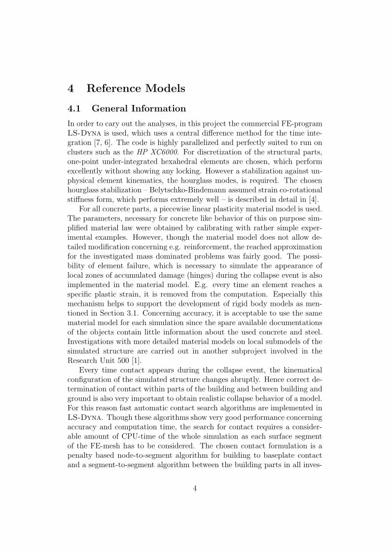
As first example for a blast simulation, a storehouse in Thuringen was chosen,which has been demolished by blast in 1998. The framework of the sevenstorys was from reinforced concrete with masonry outer walls in the first andthin concrete walls in the upper floors. The building was 22 m high, 22 mlong and 12 m wide with an approximate overall mass of 1900 tons. In thesimulation, the collapse was reached by two steps of blasting as shown inFigure 1. With the first explosion, two rows of columns were removed, afterfour seconds, the third row was destroyed. The weakening, caused by thefirst explosion was not sufficient to start the collapse of the building, so itstayed for four seconds on the two remaining rows of columns. After thesecond explosion, the building started bending forward which lead finally tothe collapse. First the complete upper six storys began to rotate, after thecuboid got into contact to the ground, it started to break into pieces.
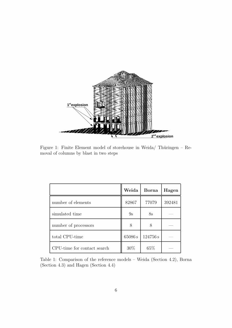
The discretized structure as depicted in Figure 1, consists of 82867 hexa-hedral finite elements. Further informations about the simulation are givenin Table 1. The results of a simulation can be seen in Figure 4.2. Unfortu-nately, the documentation of the real collapse of 1998 is limited to one movie,which makes the validation of the simulation difficult. However, the begin-ning of the collapse is fairly realistically captured, compared to the availabledata.
4.3 Silo-building in Borna/ Sachsen
The second reference model, computed on the HP-XC6000 Cluster is a silobuilding of about 25 m height with a base area of 36 mx 12 m and an ap-proximate mass of 3600 tons. All columns and girders, as well as the sixcollecting bins were from reinforced concrete. Also a few concrete walls wereincluded for stiffening reasons, however, most of the outer walls were frommasonry. Before the start of the blasting, the structure was weakened byremoving wedge-shaped parts of the inner concrete walls as shown in Fig-ure 3. The collapse in form of a bending movement to the front was realizedby one explosion, removing the first row of columns completely. During therotation and even after the first contact, the entire upper part stayed almostundeformed and was just turned over within the destruction.
5
1 explosionst
2 explosionnd
Figure 1: Finite Element model of storehouse in Weida/ Thuringen – Re-moval of columns by blast in two steps
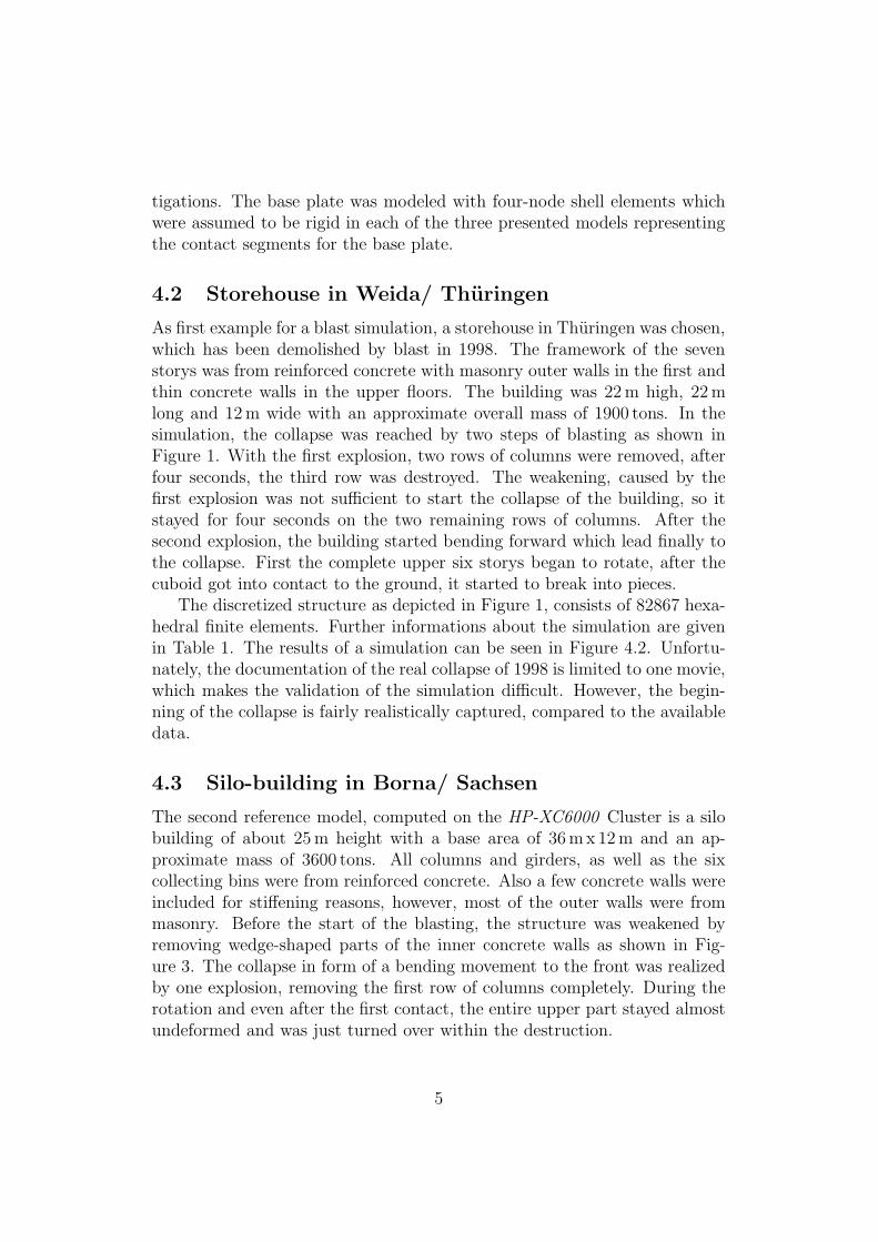
Weida Borna Hagen
number of elements 82867 77079 392481
simulated time 9s 8s —
number of processors 8 8 —
total CPU-time 65086 s 124756 s —
CPU-time for contact search 30% 65% —
Table 1: Comparison of the reference models – Weida (Section 4.2), Borna(Section 4.3) and Hagen (Section 4.4)
6
(a) t1 = 4.6 s
(b) t1 = 5.0 s
(c) t1 = 5.6 s
Figure 2: Three States of the collapse simulation
7

Blasting
weakening
Figure 3: Finite Element model of silo-building in Borna/ Sachsen
The construction was discretized with 77079 hexahedral finite elements.As before, a rigid ground plate was modeled with shell elements, providingthe segments for contact analysis. The discretized geometry is depicted inFigure 3. In Table 1 it can be seen, that the CPU-time needed for the acomplete simulation is much higher, as for the simulation of the model fromsection 4.2, though the number of elements and the simulated collapse time issmaller. The reason for this effect is the huge amount of CPU-time requiredfor the contact search algorithm. The problematic part of this structure is atthe funnels, were fairly small elements are necessary for discretization. Aftergetting into contact with the ground plate, here the contact search algorithmneeds a lot of time at every time step. In the future, alternative modelshave to be investigated in detail to achieve a more efficient analysis withoutsacrificing accuracy.
4.4 Sparkasse in Hagen/ Nordrhein-Westfalen – High-
rise with 22 storys
The third and largest example, simulated within the project is a 22 storebuilding in Hagen/ Nordrhein-Westfalen. The building with a mass of about26500 tons is 93 m high, 37 m long and 19 m wide. The main part of thestructure is a frame construction of reinforced concrete, stiffened againstshear with concrete walls. The building had been broken down in 2004.Before the blast process, all parts but the main load carrying construction
8
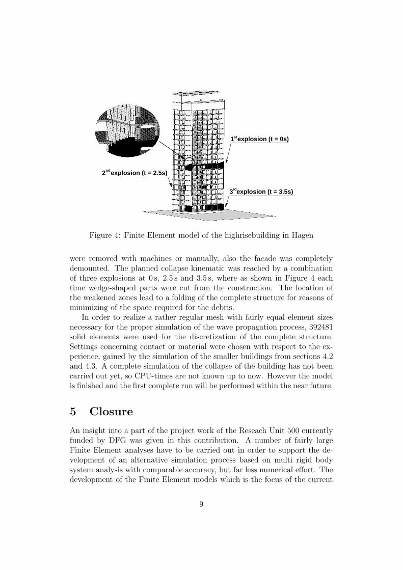
2 explosion (t = 2.5s)nd
1 explosion (t = 0s)st
3 explosion (t = 3.5s)rd
Figure 4: Finite Element model of the highrisebuilding in Hagen
were removed with machines or manually, also the facade was completelydemounted. The planned collapse kinematic was reached by a combinationof three explosions at 0 s, 2.5 s and 3.5 s, where as shown in Figure 4 eachtime wedge-shaped parts were cut from the construction. The location ofthe weakened zones lead to a folding of the complete structure for reasons ofminimizing of the space required for the debris.
In order to realize a rather regular mesh with fairly equal element sizesnecessary for the proper simulation of the wave propagation process, 392481solid elements were used for the discretization of the complete structure.Settings concerning contact or material were chosen with respect to the ex-perience, gained by the simulation of the smaller buildings from sections 4.2and 4.3. A complete simulation of the collapse of the building has not beencarried out yet, so CPU-times are not known up to now. However the modelis finished and the first complete run will be performed within the near future.
5 Closure
An insight into a part of the project work of the Reseach Unit 500 currentlyfunded by DFG was given in this contribution. A number of fairly largeFinite Element analyses have to be carried out in order to support the de-velopment of an alternative simulation process based on multi rigid bodysystem analysis with comparable accuracy, but far less numerical effort. Thedevelopment of the Finite Element models which is the focus of the current
9
presentation itselves requires parametrical studies, to learn about e.g. con-tact or material parameters. These kinds of studies, especially with suchlarge models are only possible, using high performance computers as the HP
XC6000 -Cluster. However the project is not finished yet – as mentioned inSection 4.4 one model has not been simulated yet – but a lot of experienceabout the simulation of blasting demolition have already been reached duringthe last year. This knowledge is indispensable for the further investigationsof the Research Unit 500.
6 Acknowledgments
The financial support of the German Research Foundation (DFG) (ProjectFOR 500 - Computer aided destruction of complex structures using controlledexplosives) is greatfully acknowledged.
Providing every available data such as plans and video material is veryimportant for the success of this project. For this support the authors liketo thank Dr.-Ing. Rainer Melzer.
References
[1] DFG Research Unit 500. Computer aided destruction of complex struc-tures using controlled explosives. http://www.sprengen.net/.
[2] Hochstleistungsrechner-Kompetenzzentrum Baden-Wurttemberg.http://www.hkz-bw.de/.
[3] K.-J. Bathe. Finite-Elemente-Methoden. Springer, 2002.
[4] T. Belytschko and L. P. Bindemann. Assumed strain stabilization of theeight node hexahedral element. Computer Methods in Applied Mechan-
ical Engineering, 105:225–260, 1993.
[5] Ted Belytschko, Wing Kam Liu, and Brian Moran. Nonlinear finite
elements for continua and structures. Wiley, 2000.
[6] J.O. Hallquist. LS-DYNA Theoretical Manual. Livermore SoftwareTechnology Corporation, 1991-1998.
[7] J.O. Hallquist. LS-DYNA Keyword User’s Manual. Livermore SoftwareTechnology Corporation, 1992-2005.
[8] T. J. R. Hughes. The finite element method. Dover Publ., 2000.
10
[9] J. Lippok and D. Ebeling. Bauwerkssprengungen. Weißensee-Verlag,2006.
[10] B. Moller and M. Beer. Fuzzy randomness. Springer, 2004.
[11] W. L. Wood. Practical time-stepping schemes. Clarendon Pr., 1990.
11