Embed Size (px)
Citation preview

J Computer-Aided Mater Des (2007) 14:177–200DOI 10.1007/s10820-006-9031-z
Computer-aided design of transformation toughenedblast resistant naval hull steels: Part I
A. Saha · G. B. Olson
Received: 3 June 2006 / Accepted: 1 September 2006 / Published online: 25 January 2007© Springer Science+Business Media B.V. 2007
Abstract A systematic approach to computer-aided materials design has formulateda new class of ultratough, weldable secondary hardened plate steels combining newlevels of strength and toughness while meeting processability requirements. A the-oretical design concept integrated the mechanism of precipitated nickel-stabilizeddispersed austenite for transformation toughening in an alloy strengthened by com-bined precipitation of M2C carbides and BCC copper both at an optimal ∼3 nm par-ticle size for efficient strengthening. This concept was adapted to plate steel design byemploying a mixed bainitic/martensitic matrix microstructure produced by air-coolingafter solution-treatment and constraining the composition to low carbon content forweldability. With optimized levels of copper and M2C carbide formers based on aquantitative strength model, a required alloy nickel content of 6.5 wt% was predictedfor optimal austenite stability for transformation toughening at the desired strengthlevel of 160 ksi (1,100 MPa) yield strength. A relatively high Cu level of 3.65 wt% wasemployed to allow a carbon limit of 0.05 wt% for good weldability, without causingexcessive solidification microsegregation.
Keywords Yield strength · Fracture toughness · Weldability · Copper strengthening ·Hardness · Transformation toughening · Austenite · Stability · Dispersion ·Precipitation
A. Saha (B) · G. B. OlsonDepartment of Materials Science and Engineering, Robert R. McCormick School of Engineeringand Applied Science, Northwestern University, 2220 Campus Drive, Evanston, IL 60208, USAe-mail: [email protected]
Present Address:A. SahaIntel Corporation, 2501 NW 229th Avenue, RA3-355, Hillsboro, OR 97124, USA

178 A. Saha, G.B. Olson
Fig. 1 KIC toughness versus RC hardness cross-plot for ultra-high strength martensitic steels [1]
1 Introduction
With scientific advances in the past century, the property-driven view of structureand processing for the creation of value has motivated the development of a sys-tematic strategy in computer-aided design of materials [1,2]. The approach combinesmaterials science, quantum physics and continuum mechanics in the integration ofprocess/structure/property/performance relations for predictive design of high per-formance steels as multilevel dynamic structures. Throughout the history of materialsdevelopment, there has been an ever-increasing need for stronger, tougher, morefracture resistant and easily weldable plate steels for structural applications at mini-mal cost. Unfortunately, however, any increase in strength is rarely achieved withoutconcomitant decreases in toughness and ductility, which limits the utility of most ultra-high-strength steels. The best combinations of strength and toughness have usuallybeen obtained from martensitic microstructures as shown in Fig. 1. High strengthbainitic steels have not been as successful in practice because of the coarse cementiteparticles in bainite that are detrimental to toughness. The primary benefit motivatingthe research of air-hardened steels containing bainite/martensite mixtures is the easeof processing, which finally leads to a product with good performance at a relativelylower cost. There is then the possibility of improving the strength and toughnesssimultaneously using fine-grained bainitic ferrite plates and enhancing the tough-ness by transformation toughening effects. Further improvements of strength can beachieved with co-precipitation of alloy carbides and BCC copper for easily weld-able low-carbon steels [3], where alloy carbide precipitation dissolves the deleteriouscementite.
It is now well established that the interaction of deformation-induced martens-itic transformation of dispersed austenite with fracture-controlling processes such asmicrovoid induced shear localization results in substantial improvements in fracturetoughness called Dispersed Phase Transformation Toughening (DPTT). This is thetoughening mechanism modeled and investigated in this work. Transformation tough-ening is attributed to modification of the constitutive behavior of the matrix throughpressure-sensitive strain hardening associated with the transformation volume change

Computer-aided design of transformation toughened blast resistant naval hull steels 179
[4,5]. The transformation behavior and the toughening effects are controlled by thestability of the austenite dispersion. For transformation toughening at high strengthlevels, the required stability of the austenite dispersion is quite high and can beachieved only by size refinement and compositional enrichment of the austeniteparticles. The size influences the characteristic potency of nucleation sites in theparticles while the composition influences the chemical driving force and interfacialfriction for the martensitic transformation. The size refinement and the compositionalenrichment of the austenite can be controlled with heat treatments such as multisteptempering [6].
Combining new levels of strength and toughness while meeting processabilityrequirements, the design addressed here will focus on a new class of ultratough,weldable secondary hardened bainitic/martensitic plate steels for blast resistant navalhull applications.
2 Design objectives
Looking ahead to the projected naval hull material requirements in the year 2020, theprimary design objectives motivating this research are the achievement of extremeimpact fracture toughness (Cv > 85 ft-lbs or 115 J corresponding to fracture toughness,KId > 200 ksi in1/2 or 220 MPa m1/2 and KIc > 250 ksi in1/2 or 275 MPa m1/2) at highstrength levels of 150–180 ksi (1,030–1,240 MPa) yield strength in weldable, formableplate steels with high resistance to hydrogen stress corrosion cracking (KISCC/KIC >0.5) [18,19]. Because of difficulties in measurement of KId and KIc fracture toughnessat such extreme levels, toughness of prototypes will be assessed by Charpy impact en-ergy (CV) absorption measurements; details of the KIc − CV and KId − CV toughnesscorrelation will be discussed later. The primary design goals are marked by the starin the cross-plot of KIc fracture toughness and yield strength illustrated in Fig. 2. Thisdesign aims to substantially expand the envelope marked as “steels” to the top rightcorner of the plot.
3 Design approach
Based on Cyril Smith’s [8] modern systems view of materials structure as “universalmultilevel structure with strong interactions among different levels…” this materialsdesign approach breaks down the complex nature of the structural hierarchy to betterunderstand the structure and property relations underlying the technological and eco-nomic value of materials. Our approach follows the framework of systems engineeringas outlined by Jenkins [9]. Once the final goal has been set, the structure is describedas subsystems with graphical representation of the interactions through a system flowblock diagram. The flow block diagram represents the key microstructural subsys-tems, links them to the properties they control and then to the stages of processingthat govern their dynamic evolution. Because of the complex nature of materials, itshould be realized that the interaction between the subsystems is as important as thesubsystems themselves. The systems analysis is then applied to identify and priori-tize the key structure–property and processing–structure relations. Figure 3 describesthe system structure adopted here to design a steel with the specified strength and

180 A. Saha, G.B. Olson
Fig. 2 KIC toughness versus σ yield strength cross-plot for different classes of materials [7]
toughness levels while meeting composition and processing constraints for weldabilityand hydrogen resistance.
Our system-level design integration follows a multiobjective “satisficing” approach[9], with aspects of single-objective optimization applied at the subsystem level basedon previously established quantitative structure/property relations for strength andtoughness. Quantitative design integration follows a parametric approach, expressingmicrostructural subsystem requirements in terms of thermodynamic parameters andemploying computational thermodynamics to iteratively solve for a self-consistent al-loy composition balancing the conflicting subsystem requirements. Alloy processabil-ity is addressed as constraints on overall composition and transformation temperatures.
With toughness being a major priority for this design, the matrix was chosen as asecondary hardened bainite/martensite mixture, in which cementite particles shouldbe eliminated by alloy carbide precipitation in “Stage IV” tempering, as they aredetrimental to the toughness of the steel. In addition, an optimum-stability aus-tenite dispersion in the bainitic/martensitic matrix can also help in increasing the

Computer-aided design of transformation toughened blast resistant naval hull steels 181
Fig. 3 Material system chart for design of blast resistant naval hull steels
toughness of the steel. Our previous studies [10,11] have demonstrated exceptionallylarge fracture toughness values in high-strength precipitation-hardened metastableaustenitic steels. This remarkable increase in the fracture toughness is attributableto the process of transformation toughening which will be discussed in greater de-tail later. Recent studies [12] have also shown that selection of fine Ti(C, N) as agrain refining dispersion contributes to increasing the fracture resistance by delay-ing the coalescence of microvoids among the primary voids. Studies [13] have alsosuggested that the resistance to primary void formation and coalescence is pro-portional to inclusion spacing. It is thus desirable to reduce the volume fractionof primary inclusions or coarsen inclusions for a given volume fraction. This canbe achieved by clean melt practices and tight composition control. However, engi-neering design fracture toughness parameters like KIc and KId are difficult andexpensive to measure. Thus for preliminary design analyses, small-scale inexpen-sive fracture measurements like Charpy V-notch impact energy (CV) values can beused to estimate KIc and KId. Studies of fracture toughness dependence on loadingrate measured over a temperature range [14] have shown that KIc fracture tough-ness values under static and intermediate loading are about 20% higher than theKId measured under impact loading. While it is known that KIc and CV cannotbe universally correlated [15], Barsom and Rolfe [14] have established an approx-imate relation between KIc and CV test results for conventionally grain-refined steels:
K2IC = ACV (1)

182 A. Saha, G.B. Olson
Fig. 4 Correlation between KIc and CV test results [14] for high Ni steels
where A is a constant of proportionality. Fitting Eq. 1 to results from high Ni steelsshown in Fig. 4, an empirical correlation can be established for the class of steelsexplored in this study.
According to these relationships, the CV impact toughness objective of 85 ft-lbs isequivalent to the KIc fracture toughness of 250 ksi in1/2(275 MPa m1/2) representedin Fig. 2, corresponding to a dynamic KId of 200 ksi in1/2 (220 MPa m1/2).
A fine carbide dispersion must be obtained in order to achieve the desired strengthlevel. Coherent M2C carbides have been used in secondary hardened steels that arecurrently in use [16]. Previous work [17] to optimize the carbide particle size forstrength has shown that 3 nm carbide precipitates corresponding to the transitionfrom particle shear to Orowan bypass provide maximum strength. Thermodynamicsand kinetics of carbide precipitation have to be controlled to obtain such a fine M2Ccarbide dispersion. The driving force for M2C nucleation should be maximized byproper control of the amount and ratio of carbide formers in the alloy to refine theM2C particle size. Sufficient M2C precipitation must be achieved to dissolve cementitein order to attain the desired toughness levels because coarse cementite particles areextremely deleterious as microvoid nucleation sites. Tempering times should also beminimized to prevent impurity segregation at grain boundaries.
Even if we maintain low alloy carbon levels, higher alloying content tends to reduceweldability by increasing hardenability. For any structural material, the heat-affectedzone (HAZ) adjacent to the welded joints are considered to be the weakest links.Weldability of steels is controlled by both the matrix and the strengthening dispersionstructures. As a rule of thumb, for adequate weldability of the steel C content of thealloy should be kept below 0.15 wt%. This in turn limits the C available for M2Cstrengthening. For the bainitic matrix, if we modify the hardenability of the steel, wecan obtain bainite with a much lower cooling rate. This becomes a trade-off sinceweldability can deteriorate as the hardenability increases.
Ultra-high strength steels are prone to a decrease of fracture toughness in aque-ous environments due to hydrogen assisted cracking. This reduction of toughnessis caused by intergranular brittle fracture associated with impurity segregation tograin boundaries, which may reduce toughness of the steel by as much as 80% in a
Computer-aided design of transformation toughened blast resistant naval hull steels 183
CSet Carbon Level
Weldability
CSet Carbon Level
Weldability
Castability Cu, Ni, CrCastability Cu, Ni, Cr
Refine M2C Strengthening Dispersion Mo, V, Cr, C
Maximize M2CDriving Force
SolutionTemperature
Predicted StrengthIncrement
Refine M2C Strengthening Dispersion Mo, V, Cr, C
Maximize M2CDriving Force
SolutionTemperature
Predicted StrengthIncrement
Optimize Transformation Toughening Dispersion
Austenite NickelContent
Austenite PhaseFraction
Meet StabilityRequirement
NiOptimize Transformation Toughening Dispersion
Austenite NickelContent
Austenite PhaseFraction
Meet StabilityRequirement
Ni
Set Matrix Composition Fe, Ni, Cr, Cu
Martensite StartTemperature
BainiticTransformation
CleavageResistance
Set Matrix Composition Fe, Ni, Cr, Cu
Martensite StartTemperature
BainiticTransformation
CleavageResistance
Set Copper for Strengthening Dispersion
Additional StrengthIncrement
Volume fraction ofCopper Precipitates
Cu, Cr
Partitioning of Copper by Chromium
Set Copper for Strengthening Dispersion
Additional StrengthIncrement
Volume fraction ofCopper Precipitates
Cu, Cr
Partitioning of Copper by Chromium
noiti
sop
moCl
amit
pO
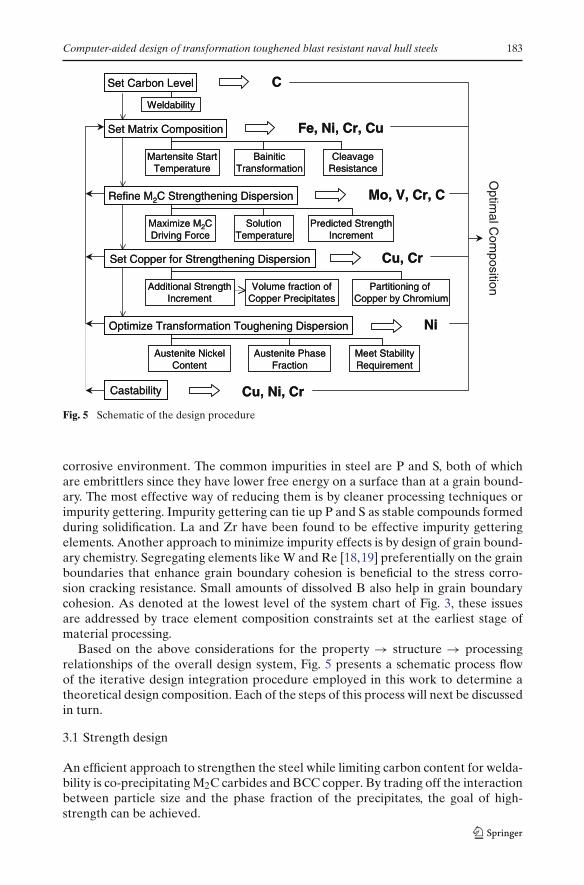
Fig. 5 Schematic of the design procedure
corrosive environment. The common impurities in steel are P and S, both of whichare embrittlers since they have lower free energy on a surface than at a grain bound-ary. The most effective way of reducing them is by cleaner processing techniques orimpurity gettering. Impurity gettering can tie up P and S as stable compounds formedduring solidification. La and Zr have been found to be effective impurity getteringelements. Another approach to minimize impurity effects is by design of grain bound-ary chemistry. Segregating elements like W and Re [18,19] preferentially on the grainboundaries that enhance grain boundary cohesion is beneficial to the stress corro-sion cracking resistance. Small amounts of dissolved B also help in grain boundarycohesion. As denoted at the lowest level of the system chart of Fig. 3, these issuesare addressed by trace element composition constraints set at the earliest stage ofmaterial processing.
Based on the above considerations for the property → structure → processingrelationships of the overall design system, Fig. 5 presents a schematic process flowof the iterative design integration procedure employed in this work to determine atheoretical design composition. Each of the steps of this process will next be discussedin turn.
3.1 Strength design
An efficient approach to strengthen the steel while limiting carbon content for welda-bility is co-precipitating M2C carbides and BCC copper. By trading off the interactionbetween particle size and the phase fraction of the precipitates, the goal of high-strength can be achieved.

184 A. Saha, G.B. Olson
Fig. 6 Power-law relationship relating hardness of related steels to yield stress from experimentaldata from Foley [21] (circles), Kuehmann [22] (triangles) and Spaulding [23] (diamonds) shown incomparison to straight-line relationship for ideal plastic material
3.1.1 Quantitative strengthening contributions
As highlighted by the system design chart (Fig. 3), the strength of the alloy will bedesigned by using quantitative strengthening models to predict its dependence on thestructure of the steel. To achieve a goal of 160 ksi (1,100 MPa) yield strength, quan-titative models will be employed to relate the contribution from dispersions of M2Ccarbide precipitates [17] and BCC copper precipitates [20] in secondary hardenedsteels. The levels of M2C carbide formers and copper will be selected based on thestrength contribution from each of these substructures. In this work, assessment ofthe yield strength of the material has been made directly from the hardness databecause of the ease and convenience in measurement of the latter. Hardness of amaterial is a direct manifestation of its resistance to plastic flow, monotonically relat-ing to yield stress. An empirical relationship has been developed between hardnessand yield stress based on experimental data from previous research on related steels:HSLA100 data from Foley [21], AerMet100 data from Kuehmann [22] and SRG C2experimental gear steel data from Spaulding [23]. The best-fit curve in a log–log plotof hardness versus yield stress has been used to determine the relationship incor-porating strain hardening effects. Figure 6 presents the experimentally measuredhardness—yield stress data from the previous research superimposed with the best-fitpower-law relationship and the theoretical straight-line relation describing the samefor an ideal plastic material [24]. The higher hardness of the empirical power-lawrelationship relative to the ideal-plastic case represents the effect of strain hardening,which is more pronounced at lower strength levels. The point at which the two curvesmeet represents the prediction limit of the relationship.
Thus, the hardness estimate for the target yield strength of 160 ksi (1,100 MPa)from the power-law relationship is 389 VHN. The relationship obtained is:
VHN = 6.116YS0.8184 (2)
where VHN (Vickers Hardness Number) is in kg/mm2 and YS (Yield Strength) isin ksi.
The first step in the design involved setting the carbon content of the alloy to ensuregood weldability. Figure 7 presents the Graville diagram summarizing effects of overall
Computer-aided design of transformation toughened blast resistant naval hull steels 185
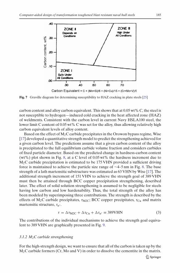
Fig. 7 Graville diagram for determining susceptibility to HAZ cracking in plate steels [25]
carbon content and alloy carbon equivalent. This shows that at 0.05 wt% C, the steel isnot susceptible to hydrogen—induced cold cracking in the heat affected zone (HAZ)of weldments. Consistent with the carbon level in current Navy HSLA100 steel, thelower limit C content of 0.05 wt% C was set for the alloy, thus allowing relatively highcarbon equivalent levels of alloy content.
Based on the effect of M2C carbide precipitates in the Orowon bypass regime, Wise[17] developed a quantitative strength model to predict the strengthening achieved fora given carbon level. The predictions assume that a given carbon content of the alloyis precipitated to the full equilibrium carbide volume fraction and considers carbidesof fixed particle diameter. Based on the predicted change in hardness-carbon content(wt%) plot shown in Fig. 8, at a C level of 0.05 wt% the hardness increment due toM2C carbide precipitation is estimated to be 175 VHN provided a sufficient drivingforce is maintained to achieve the particle size range of ∼4–5 nm in Fig. 8. The basestrength of a lath martensitic substructure was estimated as 63 VHN by Wise [17]. Theadditional strength increment of 151 VHN to achieve the strength goal of 389 VHNmust then be attained through BCC copper precipitation strengthening, describedlater. The effect of solid solution strengthening is assumed to be negligible for steelshaving low carbon and low hardenability. Thus, the total strength of the alloy hasbeen modeled by superimposing three contributions. The strength is described by theeffects of M2C carbide precipitates, τM2C; BCC copper precipitates, τCu and matrixmartensitic structure, τα′ .
τ = �τM2C + �τCu + �τα′ ≡ 389VHN (3)
The contributions of the individual mechanisms to achieve the strength goal equiva-lent to 389 VHN are graphically presented in Fig. 9.
3.1.2 M2C carbide strengthening
For the high-strength design, we want to ensure that all of the carbon is taken up by theM2C carbide formers (Cr, Mo and V) in order to dissolve the cementite in the matrix.

186 A. Saha, G.B. Olson
Fig. 8 Change in hardness as a function of alloy carbon content for M2C carbide strengtheningcontribution [17]. The arrows represent hardness increment of 175 VHN is achieved at C level of0.05 wt% set for the alloy. Experimental results of other secondary hardening steels are shown
Fig. 9 Graphical representation for contributions of the individual mechanisms to achieve thestrength goal equivalent to 389 VHN
Cementite negatively affects strength and toughness. Therefore, we want the sum ofthe atomic concentrations of Cr, Mo and V to be at least double the concentration ofC for the M2C stoichiometry.
A series of calculations were performed in order to design a steel that meets thestrength requirements. Preliminary compositions were set using the guideline (con-sistent with the HSLA100 alloy) that carbon content should be limited to 0.05 wt%for weldability (Fig. 7); Cu should be at least 1.5 wt% for significant strengthening[21,26], minimum Ni content should be at least half that of Cu to avoid hot shortness,and the relative amounts of carbide formers Cr, Mo and V was initially set equal inatomic percent. A feasibility study was then performed to ensure that this strength-ening concept, in conjunction with our approach for toughening (described later) isthermodynamically possible, i.e. all of the phases needed for precipitation strengthen-ing and nickel-stabilized austenite could co-exist at least in metastable equilibrium atprocessing temperatures. A BCC Cu-rich precipitate is necessary for Cu precipitation
Computer-aided design of transformation toughened blast resistant naval hull steels 187
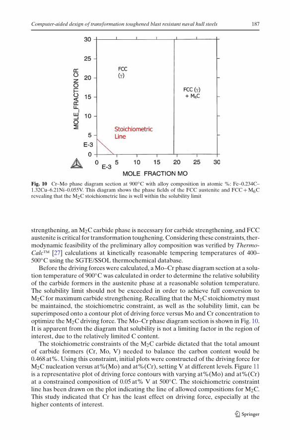
Fig. 10 Cr–Mo phase diagram section at 900◦C with alloy composition in atomic %: Fe–0.234C–1.32Cu–6.21Ni–0.055V. This diagram shows the phase fields of the FCC austenite and FCC + M6Crevealing that the M2C stoichiometric line is well within the solubility limit
strengthening, an M2C carbide phase is necessary for carbide strengthening, and FCCaustenite is critical for transformation toughening. Considering these constraints, ther-modynamic feasibility of the preliminary alloy composition was verified by Thermo-Calc™ [27] calculations at kinetically reasonable tempering temperatures of 400–500◦C using the SGTE/SSOL thermochemical database.
Before the driving forces were calculated, a Mo–Cr phase diagram section at a solu-tion temperature of 900◦C was calculated in order to determine the relative solubilityof the carbide formers in the austenite phase at a reasonable solution temperature.The solubility limit should not be exceeded in order to achieve full conversion toM2C for maximum carbide strengthening. Recalling that the M2C stoichiometry mustbe maintained, the stoichiometric constraint, as well as the solubility limit, can besuperimposed onto a contour plot of driving force versus Mo and Cr concentration tooptimize the M2C driving force. The Mo–Cr phase diagram section is shown in Fig. 10.It is apparent from the diagram that solubility is not a limiting factor in the region ofinterest, due to the relatively limited C content.
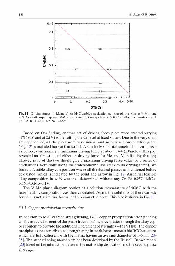
The stoichiometric constraints of the M2C carbide dictated that the total amountof carbide formers (Cr, Mo, V) needed to balance the carbon content would be0.468 at%. Using this constraint, initial plots were constructed of the driving force forM2C nucleation versus at%(Mo) and at%(Cr), setting V at different levels. Figure 11is a representative plot of driving force contours with varying at%(Mo) and at%(Cr)at a constrained composition of 0.05 at% V at 500◦C. The stoichiometric constraintline has been drawn on the plot indicating the line of allowed compositions for M2C.This study indicated that Cr has the least effect on driving force, especially at thehigher contents of interest.
188 A. Saha, G.B. Olson
Fig. 11 Driving forces (in kJ/mole) for M2C carbide nucleation contour plot varying at%(Mo) andat%(Cr) with superimposed M2C stoichiometric (heavy) line at 500◦C at alloy compositions at%Fe–0.234C–1.32Cu–6.21Ni–0.055V
Based on this finding, another set of driving force plots were created varyingat%(Mo) and at%(V) while setting the Cr level at fixed values. Due to the very smallCr dependence, all the plots were very similar and so only a representative graph(Fig. 12) is included here at 0 at%(Cr). A similar M2C stoichiometric line was drawnas before, constraining a maximum driving force at about 14.4 (kJ/mole). This plotrevealed an almost equal effect on driving force for Mo and V, indicating that anyallowed ratio of the two should give a maximum driving force value, so a series ofcalculations were done along the stoichiometric line (maximum driving force). Wefound a feasible alloy composition where all the desired phases as mentioned beforeco-existed, which is indicated by the point and arrow in Fig. 12. An initial feasiblealloy composition in wt% was thus determined without any Cr: Fe–0.05C–1.5Cu–6.5Ni–0.6Mo–0.1V.
The V–Mo phase diagram section at a solution temperature of 900◦C with thefeasible alloy composition was then calculated. Again, the solubility of these carbideformers is not a limiting factor in the region of interest. This plot is shown in Fig. 13.
3.1.3 Copper precipitation strengthening
In addition to M2C carbide strengthening, BCC copper precipitation strengtheningwill be modeled to control the phase fraction of the precipitates through the alloy cop-per content to provide the additional increment of strength (≡151 VHN). The copperprecipitates that contribute to strengthening in steels have a metastable BCC structure,which are fully coherent with the matrix having an average diameter of 1–5 nm [28–35]. The strengthening mechanism has been described by the Russell–Brown model[20] based on the interaction between the matrix slip dislocation and the second phase

Computer-aided design of transformation toughened blast resistant naval hull steels 189
Fig. 12 Driving force (in kJ/mole) for M2C carbide nucleation contour plot varying at%(Mo) andat%(V) with superimposed M2C stoichiometric line at 500 ◦C at alloy compositions at% Fe–0.234C–1.32Cu–6.2Ni
Fig. 13 Mo–V phase diagram section at 900◦C with alloy composition in atomic %: Fe–0.234C–1.32Cu–6.2Ni. This diagram shows the phase fields of the FCC austenite and FCC + V3C2 revealingthat the M2C stoichiometric line is well within the solubility limit

190 A. Saha, G.B. Olson
Fig. 14 Change in peak hardness as a function of alloy copper content for BCC copper strengtheningcontribution [20]. Experimental results of other copper strengthened steels are shown. The dottedline represents the best-fit line for one-half power law given by Eq. 5
copper-rich particle of lower shear modulus than the matrix. The shear stress has amaximum value, τmax, given by Eq. 4.
τmax = 0.041Gbf 1/2
r0(4)
where, G is the matrix shear modulus, b is the burgers vector, f is the volume fractionof precipitates and r0 is the core radius of the dislocation. The maximum strength thatcan be achieved (which empirically occurs at a particle diameter of 2–3 nm) is thusproportional to the square root of the volume fraction of the precipitate. Based onthis volume fraction dependence of the precipitate on yield stress, the peak hardeningincrement from available data of copper precipitation strengthened steels [20] wasplotted as shown in Fig. 14. The best-fit line described by a one-half power law definedthe hardening increment dependence on the alloy content (at%) of copper.
�τ(VHN) = 83.807X1/2Cu (5)
giving a strengthening coefficient within a factor of ∼1.2 of the Russell–Brown esti-mate. Based on this relationship, the hardness increment of 151 VHN can be achievedby addition of 3.25 at% Cu to the alloy composition, provided this level can be madesoluble at the alloy austenizing temperature.
3.2 Transformation toughening design
For design of tough steels for such high strength levels (160 ksi or 1,100 MPa YS)we need to develop a fully secondary hardened microstructure with high stabilityaustenite produced by precipitation. At high strength levels we need high stability of
Computer-aided design of transformation toughened blast resistant naval hull steels 191
precipitated austenite since the mechanical driving force for transformation is veryhigh. This design seeks to improve the toughness of higher strength steels by utilizingthe beneficial properties of Ni-stabilized precipitated austenite. This form of aus-tenite can precipitate during annealing or tempering at elevated temperatures aboveabout 470◦C. The fact that this dispersed austenite forms by precipitation is significantbecause it allows greater overall control of the amount and stability of the austenite.Further processing and treatments can be used in the form of multistep temperingto first nucleate particles in a fine form at a higher tempering temperature and thencomplete Ni enrichment during completion of precipitation strengthening (cementiteconversion to M2C) at a lower final tempering temperature [4,6].
Shear localization by microvoid nucleation is known to be the most dominantfracture mode in high toughness steels. Studies [36] have shown that fine particledispersions with adherent interfaces are most useful for controlling microvoid nucle-ation. The most promising microstructure modification is achieved by nucleating anoptimal stability austenite dispersion, which increases toughness by suppressing mi-crovoid nucleation to higher strain levels. Thus, emphasis will be put on the designof intralath dispersions, as the greater stability associated with their finer size makesthem the primary toughening form of austenite precipitates.
The austenite dispersion must have sufficient stability and proper formation kinet-ics to ensure maximum toughening enhancement. Other factors controlling the sta-bility of austenite are particle size and stress state sensitivity, the latter being relatedto the transformational volume change. The Olson–Cohen classical heterogeneousmartensitic nucleation model can be applied to describe dispersed austenite stabilityfor transformation toughening [4]. Stability of an austenite precipitate is defined bychemical and mechanical driving force terms. At the Mσ
s temperature (where trans-formation occurs at yield stress) for the crack-tip stress state, the total driving forceequals the critical driving force for martensite nucleation, as represented by Eq. 6.
�Gch + σyd�Gσ
dσ
∣∣∣∣cracktip
= −[
2γ
nd+ G0 + Wf
]
(6)
Rearranging the terms and substituting a dependence of defect potency on particlevolume Vp [37], we can define a convenient stability parameter:
�Gch + Wf + Kln(Vp)
= −[
σyd�Gσ
dσ
∣∣∣∣cracktip
+ G0
]
(7)
�Gch is the transformation chemical free energy change and Wf is the athermal fric-tional work term �Gch is temperature and composition dependent while Wf is onlycomposition dependent. Wf will vary with tempering temperature due to the changein austenite composition. σy is the yield stress of the material, �Gσ is set by the stressstate and G0 is a fixed stored energy term. K is a proportionality constant, γ is thenucleus specific interfacial energy and d is the crystal interplanar spacing.
The austenite stability for a given set of conditions or service temperature for agiven dispersion can be assessed by the parameter given by the left-hand side of Eq. 7.If we assume an austenite particle size equivalent to that achieved in previous studiesof AF1410 and AerMet100 steels, our austenite stability parameter becomes the sumof the chemical driving force for transformation of FCC austenite to BCC martensiteat room temperature (300 K) and the frictional work term for martensitic interfacialmotion: �Gch + Wf. ThermoCalc™ can be used with an appropriate thermochemical

192 A. Saha, G.B. Olson
Fig. 15 Optimal room temperature (300 K) austenite stability plotted as a function of Vickers Hard-ness Number (VHN). The shaded region shows our range of interest for austenite stability corre-sponding to a yield strength requirement of 150–180 ksi (1030–1240 MPa) after extrapolation of datafrom previous alloys, AF1410 and AerMet100
Table 1 Target chemical driving force (�Gch) + frictional work (Wf) value
Alloy Rockwell C Hardness Rc Vickers Hardness VHN (kg/mm2) �Gch + Wf J/mol
AerMet 100 54 577 4350AF1410 48 484 3600Design 40 389 2837
database [38] to predict the temperature and compositional dependence of the chemi-cal energy term. Ghosh and Olson [38,39] have modeled the composition dependenceof the frictional work term as a power law with an exponent of 0.5 and a fit to exper-imental data. Appropriate superposition laws considering relative strengths of thesolutes were applied for complex systems. The model is represented in Eq. 8.
Wf =√
∑
i
(
KiX1/2i
)
+√
∑
j
(
KjX1/2j
)
+√
∑
k
(
KkX1/2k
)
+ KCoX1/2Co (8)
where the K’s represent the coefficients used to fit the solid solution strengtheningdata and i = C, N; j = Cr, Mn, Mo, Nb, Si, Ti, V; and k = Al, Cu, Ni, W. Equation 7further indicates that the stability parameter is a linear function of the yield strengthof the material.
Thorough studies of transformation toughening [10,11] have demonstrated thatmaximum toughening occurs at the Mσ
S temperature for the crack-tip stress state, thusquantifying an optimal austenite stability. The strength dependence of this optimalstability level at fixed VP was determined from previous dispersed-phase transforma-tion toughening optimization experiments on the AF1410 and AerMet100 steels [40].Figure 15 gives a plot of the measured optimal stability, �Gch +Wf, at room tempera-ture against Vickers hardness of the alloy. The required room temperature stability ofthe austenite dispersion projected from the hardness (or strength) requirement of thedesign is marked by the shaded region in the figure and quantitatively expressed inTable 1. To achieve a goal of 160 ksi (1,100 MPa) yield strength equivalent to Vickershardness of 389 (Rc40 equivalent), the estimated value of �Gch +Wf for the requiredstability is determined to be 2,837 J/mole.

Computer-aided design of transformation toughened blast resistant naval hull steels 193
Fig. 16 Fraction of Ni in austenite and phase fraction of austenite in alloy versus mole fraction of Niat 500◦C with alloy composition in weight%: Fe–0.05C–3.65Cu–1.85Cr–0.6Mo–0.1V
The design of transformation-toughened austenite has been calibrated against thisstability parameter to determine the optimal level of austenite-stabilizing nickel in thealloy. Plots of both the phase fraction of austenite and nickel content in the austenitephase versus alloy atomic fraction Ni were computed. Figure 16 was calculated atan estimated final tempering temperature of 500◦C for substitutional diffusion andrevealed that a minimum of 3.5 at% Ni is required to get austenite and a maximumcontent of nickel in the austenite of about 0.30 could be obtained. It also showedthat at the 6.25 at% Ni composition from initial feasibility studies, about a 0.10 phasefraction of austenite would be formed as shown by the arrows. This compares wellto the phase fraction of austenite employed in previous transformation toughenedsteels. We thus set the alloy Ni level to 6.25 at%, which also saturates the austenite Nicontent to 30 at%.
After conducting the feasibility study mentioned earlier and verifying that thecorresponding austenite stability was within the design limits given in Fig. 15, a ther-modynamically viable alloy composition was found using 6.25 at% Ni. This Ni levelwas deemed acceptable as it fell well within the nickel content guidelines, while beinglow enough to limit the material cost.
3.3 Composition integration
The overall composition was next optimized so that all of the phases necessary forstrengthening and toughening are simultaneously present. The full sequence of iter-ative calculations followed the flow chart of Fig. 5. Since the maximum M2C drivingforce at fixed total solute is obtained with no chromium, equilibrium phase calcula-tions were done for the initial feasible composition. For this initial composition, itwas found that the copper added for precipitation strengthening went instead intothe austenite phase. It was found that Cr partitions Cu out of austenite and into theBCC precipitate phase effectively at 2 at% and above, and the Cr content was thusset to this minimum value. The iterative calculation sequence of Fig. 5 then yielded a
194 A. Saha, G.B. Olson
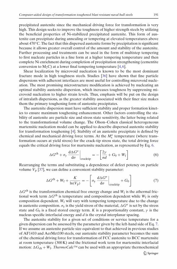
Fig. 17 Equilibrium mole fraction of phases in the alloy as a function of temperature, showing thatthe alloy is solution treatable at 900 ◦C
self-consistent alloy composition meeting all phase relation requirements. The compo-sition was then further evaluated from the viewpoint of processability requirements.
4 Processing considerations
4.1 Solution treatment temperature and allotropic transformations
A solution treatment temperature of 900◦C was chosen based on previous optimiza-tion studies [22,41] on grain size dependence of hardness and toughness based on 1-hsolution treated samples in secondary hardened steels. With the increased levels ofCu and Cr it was confirmed that the alloy was solution treatable at 900◦C as shownby the ThermoCalc™ phase fraction plot in Fig. 17.
For this alloy composition, our martensite and bainite kinetic models predict an MStemperature of 298◦C and a bainite start (BS) temperature of 336◦C. These should besufficiently high to allow formation of bainite/martensite mixtures with air-cooling.
4.2 Scheil simulation for microsegregation behavior
Solidification of alloys generally occurs with segregation, which can have a strongeffect on the alloy’s final properties. Thus, it is important to model segregation to assessthe processability of the designed alloy. This investigation uses thermodynamic mod-eling to predict microsegregation of the as-cast material. Macrosegregation effects canalso be addressed by modeling liquid buoyancy associated with the microsegregationamplitude but are not addressed in this assessment.
Computer-aided design of transformation toughened blast resistant naval hull steels 195
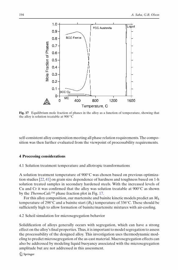
Fig. 18 Scheil simulation for evolution of the fraction solid with cooling for designed alloy Fe–0.05C–6.5Ni–3.65Cu–1.84Cr–0.6Mo–0.1V (wt%) in comparison with equilibrium solidification
Table 2 Amplitude of microsegregation with respect to each alloying element predicted by Scheilsimulation at 95% solidification
Alloying elements Ni Cu Cr Mo V
Nominal alloy composition—Calloy (at%) 6.38 3.31 2.04 0.36 0.11Microsegregation amplitude C0.95 − C0 (at%) 1.29 1.67 0.72 0.34 0.05
Scheil simulation is a fast method of estimating microsegregation [42]. The mainapproximations are infinite diffusion in the liquid but no diffusion in the solid phase.This has been coupled to the multicomponent SGTE thermodynamic database usingThermoCalc™ from which the solid/liquid equilibrium was calculated repeatedly dur-ing the simulation. Figure 18 presents the solidification simulation result as tempera-ture versus fraction solid using the non-equilibrium Scheil simulation and compares itwith the full equilibrium case. Figure 19 presents the composition profiles calculatedby the Scheil simulation showing the degree of microsegregation in the solid aftersolidification. Here, the fraction of solid is equivalent to position relative to a dendritearm center. Previous comparison with more rigorous calculations incorporating solidback diffusion indicate that the Scheil result at 95% solid is a reasonable estimateof the maximum microsegregation amplitude under typical ingot solidification condi-tions [43]. The results presented in Table 2 predict that Mo has the greatest potentialfor segregation. However, since the level of Mo in the alloy is relatively low, no seri-ous Mo microsegregation problems are predicted for the designed composition. Whilethe variation of Cu is significant, it was assessed to be acceptable for homogenizationtreatment at 1,200◦C.

196 A. Saha, G.B. Olson
Fig. 19 Scheil simulation for composition profile of each alloying element after solidification fordesigned alloy Fe–0.05C–6.5Ni–3.65Cu–1.84Cr–0.6Mo–0.1V (wt%). Solid fraction corresponds toposition relative to dendrite arm center
Fig. 20 Room temperature (300 K) stability of austenite as a function of tempering temperature. Therequired stability is predicted for 490◦C
4.3 Selection of tempering temperature
Using multistep tempering to initially nucleate austenite at a high tempering tem-perature, the austenite stability for this transformation toughened alloy is dependenton the final tempering temperature. With the alloy composition fixed, the austenitestability was then calculated as a function of tempering temperature as shown inFig. 20. It illustrates that the �Gch + Wf value of 2836 J/mole desired for this alloy isachieved for a tempering temperature of 490◦C, very close to the originally assumedtemperature of 500◦C.
Based on the design calculations, we derive a composition for the ultratough, highstrength weldable plate steel (in wt%) with final tempering at 490◦C: Fe–0.05C–3.65Cu–6.5Ni–1.84Cr–0.6Mo–0.1V.

Computer-aided design of transformation toughened blast resistant naval hull steels 197
The composition should be solution treatable at 900◦C, with predicted MS and BStransformation temperatures of 298◦C and 336◦C, respectively. Based on previoustransformation toughened steels, it is planned that initial tempering at a slightly ele-vated temperature will be employed to nucleate the austenite before tempering at490◦C to enrich the Ni content to the designed level. In our judgment, the highest riskassumption of this design is that fine austenite can be heterogeneously nucleated onCu particles as effectively as it has been observed to nucleate on M2C carbides [40].The observed effectiveness of Cu as a nucleant in numerous alloy systems [44,45]supports this assumption.
5 Summary and conclusions
A systematic strategy in computer-aided design of materials has been successfullyapplied to demonstrate feasibility of an ultratough high-strength weldable platesteel for naval hull applications. The approach integrated processing/structure/prop-erty/performance relations with mechanistic models to achieve the desired quantita-tive property objectives. Quantitative models were used to design the toughening andstrengthening dispersions, which were the two major property requirements to be metunder stringent processability constraints.
The overall strategy behind the thermodynamic modeling has been to map themechanical properties objectives to structure and then to thermodynamic parame-ters to set goals for the design of the microstructural subsystems. The Olson–Cohenmodel for heterogeneous martensitic nucleation aided the determination of a thermo-dynamic stability parameter for the austenite. The optimal stability of the transforma-tion-toughened austenite was calibrated against the parameter (�Gch+Wf) combiningthermodynamic driving force and interfacial friction to obtain the required toughness,which was the top priority of this design. Then, based on the strength requirementprojected to hardness values, the design space was identified. The alloy compositionand the processing conditions were subsequently determined by conforming to theseparametric design requirements.
The explored design concept is based on the mechanism of dispersed austen-ite stabilization for transformation toughening adapted to weldable high strengthsteels. The concept employs mixed bainitic/martensitic microstructures produced byair-cooling of solution-treated plate, combined with copper and alloy carbide pre-cipitation strengthening during secondary tempering, constrained by a low carboncontent for weldability. A fine particle dispersion of optimal ∼3–5 nm size for effec-tive strengthening was designed by precipitation of M2C carbides and BCC copperfrom a highly supersaturated BCC solution. The carbon content of the alloy was set at0.05 wt% to meet weldability constraints. Based on the carbon level set, a quantitativecarbide-strengthening model was used to determine the strength contribution fromM2C carbides, with the driving force for M2C precipitation maximized at ∼14 kJ/mole(while initially maintaining a stoichiometric balance between carbon and the carbideformers Mo, Cr, V) to obtain a fine 3–4 nm precipitate particle size. The additionalstrengthening required to meet the yield strength goal of 160 ksi (1,100 MPa) wasachieved by setting an optimal level of copper at 3.65 wt% based on a quantitativecopper-strengthening model. This relatively high Cu level was necessary to allow thelow carbon limit. A high Ni/Cu ratio (1.8) was also maintained in the multicomponentalloy design to prevent hot shortness problems during processing.

198 A. Saha, G.B. Olson
Transformation toughening arises from dispersed austenite precipitates, whichundergo a martensitic transformation at the crack-tip stress state. This leads to inhibi-tion of crack growth by delay of microvoid shear localization during ductile fracture.Thus to achieve high toughening by this mechanism, required stability of the austen-ite was designed by optimizing Ni as an FCC stabilizer. Thermodynamic calculationspredicted an alloy Ni content of 6.5 wt% to enable the equilibrium nickel content of30% in the austenite to meet the requirement for transformation toughening.
The design also revealed that although Cr did not have a strong effect on the drivingforce for carbide precipitation, it helped in partitioning Cu out of the austenite phasefor effective copper precipitation strengthening; the alloy Cr level was set at 1.8 wt%.The processability conditions were then evaluated under stringent restrictions for thedesigned alloy (Fe–0.05C–3.65Cu–6.5Ni–1.84Cr–0.6Mo–0.1V; wt%) based on solutiontreatment condition, microsegregation behavior and tempering condition. A designsolution treatment condition of 900◦C for 1 h was found sufficient to dissolve M2C car-bides without excessive austenite grain growth. No serious microsegregation problemswere predicted for the designed composition based on results from Scheil simulation.A final tempering temperature of 490◦C (after a higher temperature austenite nucle-ation step) was predicted to achieve sufficient austenite stability for transformationtoughening. Thus, thermodynamic calculations demonstrated feasibility of combiningcopper and M2C carbide precipitation for strengthening in combination with nickel-stabilized austenite for transformation toughening in a relatively low cost weldableplate steel.
Acknowledgements This research was carried out under the financial support by the Office of NavalResearch (ONR) under Grant number N00014-01-1-0953 as a part of the ONR Grand Challenge inNaval Materials by Design. The authors are thankful to Dr. Gautam Ghosh (Northwestern Univer-sity), Dr. C. J. Kuehmann (QuesTek Innovations LLC) and Dr. H. J. Jou (QuesTek Innovations LLC)for their helpful discussions during the alloy design process.
References
1. Olson, G.B.: Computational Design of Hierarchically Structured Materials. Science 277, 1237–1242 (1997)
2. Olson, G.B.: Pathways of Discovery: Designing a New Material World. Science 288 993–998 (2000)3. Gagliano, M.S., Fine, M.E.: Precipitation Kinetics of Niobium Carbide and Copper in a Low
Carbon, Chromium-Free Steel. CALPHAD 25, 207–216 (2001)4. Haidemenopoulos, G.N., Olson, G.B., Cohen, M.: Dispersed-Phase Transformation Toughening in
Ultrahigh-Strength Steels In: Olson, G.B., Azrin, M., Wright, E.S. (eds.) Innovations in Ultrahigh-Strength Steel Technology (34th Sagamore Army Materials Research Conference), pp. 549–593.US Government Printing Office, Washington DC, Lake George, NY (1990)
5. Socrate, S.: Mechanics of Microvoid Nucleation and Growth in High-Strength MetastableAustenitic Steels Doctoral Dissertation, Department of Materials Science and Engineering,Massachusetts Institute of Technology, Cambridge, MA (1995)
6. Olson, G.B., Kuehmann, C.J.: Transformation Toughening in Dispersed Phase Systems In: Austen-ite Formation and Decomposition Symposium in Mat Sci & Tech 2003 Proc (ISS & TMS), pp.493–504. Chicago, IL (2003)
7. Ashby, M.F.: Materials Selection in Conceptual Design In: Proc. Ashby Symp. On MaterialsDesign, ASM World Materials Congress, Chicago, IL (1988)
8. Smith, C.S.: A Search for Structure. MIT Press, Cambridge, MA (1981)9. Jenkins, G.M. The Systems Approach. In: Beishon, J., Peters, G. (eds.) Systems Behavior, pp.
56–79. Open University Press, Birmingham, UK (1972)10. Stavehaug, F.: Transformation Toughening of γ ’-Strengthened Metastable Austenitic Steels Doc-
toral Dissertation, Department of Materials Science and Engineering, Massachusetts Institute ofTechnology, Cambridge, MA (1990)

Computer-aided design of transformation toughened blast resistant naval hull steels 199
11. Leal, R.H.: Transformation Toughening of Metastable Austenitic Steels. Doctoral Dissertation,Department of Materials Science and Engineering, Massachusetts Institute of Technology, Cam-bridge, MA (1984)
12. Hsieh, K.C.: Fracture Toughness of Ti-modified Air-melted UHS Steels Doctoral DissertationProposal, Department of Materials Science and Engineering, Northwestern University, Evanston,IL (2000)
13. Garrison, W.M., Handerhan, K.J. Fracture Toughness: Particle-Dispersion Correlations In: Olson,G.B., Azrin, M., Wright, E.S. (eds.) Innovations in Ultrahigh-Strength Steel Technology (34thSagamore Army Materials Research Conference), pp. 443–466. US Government Printing Office,Washington DC, Lake George, NY (1990)
14. Barsom, J.M., Rolfe, S.T.: Fracture and Fatigue Control in Structures: Applications of FractureMechanics. Prentice-Hall Inc., Englewood Cliffs, NJ 159–188 (1987)
15. Ritchie, R.O., Francis, B., Server, W.L.: Evaluation of toughness in ALSL 4340 alloy steel austen-itized at low and high temperatures Metall. Trans. A 7A, 831–838 (1976)
16. Ghosh, G., Campbell, C.E., Olson, G.B.: An Analytical Electron Microscopy Study of Parae-quilibrium Cementite Precipitation in Ultra-high Strength Steel Metall. Mater. Trans. A 30A,501–512 (1999)
17. Wise, J.: Systems Design of Advanced Gear Steels Doctoral Dissertation, Department of MaterialsScience and Engineering, Northwestern University, Evanston, IL (1998)
18. Geng,W.T., Freeman, A.J., Olson, G.B.: Influence of Alloying Additions on Grain BoundaryCohesion of Transition Metals: First-principles Determination and its Phenomological Extension.Phys. Rev. B 63, 165415 (2000)
19. Kantner, C.D.: Designing Strength, Toughness and Hydrogen Resistance: Quantum Steel Doc-toral Dissertation, Department of Materials Science and Engineering, North-western University,Evanston, IL (2002)
20. Russell, K.C., Brown, L.M.: A Dispersion Strengthening Model Based on Differing Elastic ModuliApplied to the Iron-Copper System Acta Metall. 20, 969–974 (1972)
21. Foley, R.P., Fine, M.E.: Microstructure and Property Investigation of Quenched and TemperedHSLA-100 Steel In: DeArdo, A.J. (ed.) ISS, Proceedings of the International Conference onProcessing, Microstructure and Properties of Microalloyed and Other Modern High StrengthLow Alloy Steels, pp. 315–329. Warrendale, PA (1991)
22. Kuehmann, C.J.: Thermal Processing Optimization of Nickel-Cobalt Ultrahigh-Strength SteelsDoctoral Dissertation, Department of Materials Science and Engineering, Northwestern Univer-sity, Evanston, IL (1994)
23. Spaulding, D.: Grain Boundary Cohesion and Segregation in Ultrahigh Strength Alloy Steels Doc-toral Dissertation, Department of Materials Science and Engineering, North-western University,Evanston, IL (1995)
24. Ashby, M.F., Jones, D.R.H.: Engineering Materials: An Introduction to their Properties andApplication. Pergamon Press, New York (1980)
25. Somers, B.R. Introduction to the Selection of Carbon and Low-Alloy Steels In: ASM Handbook:Welding, Brazing, and Soldering, 6th edn., pp. 405–407. ASM International, Metals Park, Ohio(1993)
26. Gagliano,M.S.: Co-precipitation of Copper and Niobium Carbide in a Low Carbon Steel Doc-toral Dissertation, Department of Materials Science and Engineering, North-western University,Evanston, IL (2002)
27. Sundman, B., Jansson, B., Andersson, J.: The Thermo-Calc databank system CALPHAD 9, 153–190 (1985)
28. Goodman, S.R., Brenner, S.S., Low, J.R.: An FIM-Atom Probe Study of the Precipitation ofCopper from Iron-1.4 At. Pct Copper. Part I: Field-Ion Microscopy Metall. Trans. A 4, 2363–2369(1973)
29. Goodman, S.R., Brenner, S.S., Low, J.R.: An FIM-Atom Probe Study of the Precipitation ofCopper from Iron-1.4 At. Pct Copper. Part II: Atom Probe Analyses Metall. Trans. A 4, 2371–2378 (1973)
30. Phythian, W.J., Foreman, A.J.E., English, C.A., Buswell, J.T., Hetherington, M., Roberts, K.,Pizzini, S.: The Structure and Hardening Mechanism of Copper Precipitation in Thermally Agedor Irradiated Fe-Cu and Fe-Cu-Ni Model Alloys In: Stoller, R.E., Kumar, A.S., Gelles, D.S. (eds.)Effects of Radiation on Materials: 15th International Symposium, pp. 131–150. ASTM STP 1125,Philadelphia, PA (1992)
31. Deschamps, A., Militzer, M., Poole, W.J.: Precipitation Kinetics and Strengthening of a Fe-0.8wt% Cu alloy ISIJ Int. 41, 196–205 (2001)

200 A. Saha, G.B. Olson
32. Worrall, G.M., Buswell, J.T., English, C.A., Hetherington, M.G., Smith, G.D.W.: A Study of thePrecipitation of Copper Particles in a Ferrite Matrix J. Nucl. Mater. 148, 107–114 (1987)
33. Hornbogen, E. In: Speich, G.R., Clark J.B. (eds.) Precipitation from Iron-Base Alloys. Gordonand Breach, New York, NY (1965)
34. Pizzini, S., Roberts, K.J., Phythian, W.J., English, C.A., Greaves, G.N.: A Fluorescence EXAFSStudy of the Structure of Copper-rich precipitates in Fe-Cu and Fe-Cu-Ni Alloys Phil. Mag. Lett.61, 223–229 (1990)
35. Phythian, W.J., Dumbill, S., Brown, P., Sinclair, R.: Stability of Thermally Induced Copper Pre-cipitates Under Neutron Irradiation In: Proceedings of the 6th International Symposium onEnvironmental Degradation in Nuclear Power Systems –Water reactors, pp. 729-737. TMS (1993)
36. Gore, M.J., Olson, G.B., Cohen, M.: Grain-Refining Dispersions and Properties in UltrahighStrength Steels In: Olson, G.B., Azrin, M., Wright, E.S. (eds.) Innovations in Ultrahigh-StrengthSteel Technology (34th Sagamore Army Materials Research Conference), pp. 425–441. US Gov-ernment Printing Office, Washington DC, Lake George, NY (1990)
37. Olson, G.B., Tsuzaki, K., Cohen, M.: Statistical Aspects of Martensitic nucleation. In: Cargill,G.S., Spaepen, F., Tu, K.N. (eds.) David Turnbull Symposium on Phase Transitions in CondensedSystems, vol. 57, pp. 127–148. MRS, Pittsburgh, PA (1987)
38. Ghosh, G., Olson, G.B.: Kinetics of FCCBCC Heterogeneous Martensitic Nucleation – I. TheCritical Driving Force for Athermal Nucleation Acta Mater. 42, 3361–3370 (1994)
39. Ghosh, G., Olson, G.B.: Kinetics of FCCBCC Heterogeneous Martensitic Nucleation – II. ThermalActivation Acta Mater. 42, 3371–3379 (1994)
40. Lippard, H.E.: Microanalytical Investigations of Transformation Toughened Co–Ni Steels Doc-toral Dissertation, Department of Materials Science and Engineering, North-western University,Evanston, IL (1999)
41. Campbell, C.E., Olson, G.B.: Systems design of high performance stainless steels I. Conceptualand computational design J. Comput. Aided Mat. Design 7, 145–170 (2000)
42. Scheil, E.: "Bemerkungen zur Schichtkristallbildung Z. Metallkd. 34, 70–72 (1942)43. Lippard, H.E., Campbell, C.E., Bjorklind, T., Borggren, U., Kellgren, P., Dravid, V.P., Olson, G.B.:
Microsegregation behavior during solidification and homogenization of AerMet100 steel Metall.Mater. Trans. B 29, 205–210 (1998)
44. Hono, K., Ping, D.H., Ohnuma, M., Onodera, O.: Cu Clustering and Si Partitioning in the EarlyCrystallization Stage of an Fe73.5Si13.5B9Nb3Cu1 Amorphous Alloy Acta Mater. 47, 997–1006(1999)
45. Ohkubo, T., Kai, H., Ping, D.H., Hono, K., Hirotsu, Y.: Mechanism of Heterogeneous Nucleationof α-Fe Nanocrystals from Fe89Zr7B3Cu1 Amorphous Alloy Scripta Mater. 44, 971–976 (2001)