Embed Size (px)
Citation preview

Compute Blade Built-in LAN Switch Module
Software Manual
Configuration Settings, Vol. 2Ver.10.5 and 10.7 and 11.6 compatible
BSLANSW-S008X-50
MK-99COM090-01
HITACHI

Applicable product
This manual describes model Compute Blade Built in LAN Switch Module. It also describes Built in LAN Switch Module software Ver.10.5 and 10.7 and 11.6 functions. Software functions supported by software OS-L3A and OS-L3SA is also described.
-------------------------------------------------------------------The BladeSymphony server name has been changed to Hitachi Compute
Blade. If you are using BladeSymphony based server products, substitute references to Hitachi Compute Blade with BladeSymphony.
This manual describes as substitution product code GV-BE2LSW1X1-Y for GV-BE2LSW1XR-Y and GV-BE2LSW2X1-Y for GV-BE2LSW2XR-Y.
If you use OS-L3SA, please add the prefix of ‘0/’ to the interface number of gigabitethernet to be specified by some commands.
-------------------------------------------------------------------
Caution when exporting
The necessary procedures are to be adopted when exporting this product after first confirming the regulations of the Foreign Exchange and Foreign Trade Law, U.S. export control related regulations, etc.If any questions remains, please consult with our sales department.
Trademarks
Cisco is a registered trademark of U.S. Cisco Systems, Inc. in the U.S. and other countries.Ethernet is a product name of the Xerox Corp.IPX is a trademark of Novell,Inc.Microsoft is a registered trademark of the Microsoft Corp. in the U.S. and other countries.Octpower is a trademark of NEC Corporation.UNIX is a registered trademark in the U.S. and other countries exclusively licensed by X/Open Company Limited.Windows is a registered trademark of the Microsoft Corp. in the U.S. and other countries.Other company names and product names are trademarks or registered trademarks of their respective companies.
Thoroughly read and store this manual
Read and thoroughly understand safety-related explanations before using this product.Keep this manual in a location close at hand for easy reference.
Note
The contents of this manual may be modified at any time for improvement without notice.
Issue dates
Jan. 2014 (8th edition) BSLANSW-S008X-50
Copyright
Copyright (c) Hitachi, Ltd. 2006 - 2014. All rights reserved.

Summary of amendments
8th editionIntegrated the description of all switch model.
In addition to the above changes, minor editorial corrections have been made.
7th edition
Addtion of some product code.
6th edition
The BladeSymphony server name has been changed to Hitachi Compute Blade.
5th edition
Model Name addition
4th edition
In addition to the above changes, minor editorial corrections have been made.
Item Changes
3.10.1 Changing which frames are subject to priority determination
• This item was added.
3.13 Actions When Multiple Matching QoS Entries are Detected
• This section was added.
5 Layer 2 Authentication • This chapter was added.
6.2.6 Limit on the number of terminals that can be authenticated
• This item was added.
6.2.7 Moving authenticated terminals between ports
• This item was added.
6.2.8 VLAN-based authentication (dynamic) operation modes
• This item was added.
6.2.9 Blocking traffic from authenticated terminals
• This item was added.
9.3.7 Restoring access to the first RADIUS server after intervention by the dead interval functionality
• This item was added.
10 DHCP Snooping • This chapter was added.
11.3.5 GSRP VLAN group-only Control Function
• This item was added.
12.1.5 Setting GSRP VLAN group-only control
• This item was added.
13.1.6 Tracking functionality • A description of Tracking functionality was added.
13.1.7 Supported VRRP specifications • A description of the Supported VRRP specifications was added.
13.1.8 Notes on Using VRRP • A description of the Notes on Using VRRP was added.
15 Uplink Redundancy • This chapter was added.

[Ver. 10.7]
Location Changes
1.1.8 Notes on Using Filtering • The description of "(4) Filter for the IPv6 packet having the extended header" was added.• The description of “(6) Operation at filter entry change" was added.
3.1.4 Notes on Using Flow Detection • The description of "(4) QoS flow detection for the IPv6 packet having the extended header" was added.
• The description of "(5) Operation at QoS Entry Change" was added.
8 Web Authentication • The description of the static VLAN Mode was added.• The name of the existing dynamic VLAN mode was changed to the legacy mode.• The description of the dynamic VLAN mode was newly added.• The description of the URL redirect function in the dynamic VLAN mode was added.
8.1.6 Preparation of the RADIUS authentication method
• NAS-IPv6-Address was added.
8.2.6 Method of Exclusion from Authentication
• This section was added.
9 MAC Authentication • This chapter was added.
14 uplink-failover • The description of the uplink failover extended function was added.
14.2 Note Required When Uplink Failover is Used
• "(5) Notes for the feature set uplink-failover" and "(6) Precautions required during uplink failover function" was added.
18 L2 Loop Detection • This chapter was added.

[Ver. 10.5.A.A]
In addition to the above changes, minor editorial corrections have been made.
[Ver. 10.5.A]
Unreleased
[Ver. 10.5]
Unreleased
[Ver. 10.4]
Unreleased
Item Changes
1.1.3 Flow Detection Mode • Added a description regarding how to select flow detection modes.
1.1.4 Flow Detection Conditions • Added a description regarding how to specify the range of the TCP/UDP port number.Modified the description regarding the flow detection conditions for the degree of user priority.
1.2.5 Setting to Relay/Discard Using IP or TCP/UDP Header
• "(3) Setting whose flow detection conditions are the range of the TCP/UDP port number"was added
2.2.1 User Priority Mapping • Added Note (*) to Table 2-2, "Mapping User Priority and CoS Value".
3.1.1 Receiving-side Flow Detection Mode • Added a description regarding how to select flow detection modes.
3.1.2 Flow Detection Conditions • Added a description regarding how to specify the range of the TCP/UDP port number.Modified the description regarding the flow detection conditions for the degree of user priority.
3.2.3 Setting for Controlling QoS in the Range of the TCP/UDP Port Number
• This item was added
3.7.1 Rewriting User Priority • Modified the description regarding how to rewrite the degree of user priority.• Made a modification in reply to the measure of taking over the degree of user priority.
3.7.2 Taking Over User Priority • This item was added
3.8.2 Setting the Process of Taking Over User Priority
• This item was added
3.9.2 Checking the Process of Taking Over User Priority
• This item was added
3.10.2 CoS Value and Queueing Priority • Made a modification in reply to the measure of taking over the degree of user priority.
4 Transmission Control • The description of 10GBASE-R was added to” 4-4 Allowable WFQ Range”• The description of 10GBASE-R was added to” 4-5 Setting range of Port band control”
4.1.4 Port Bandwidth Control • Added a description regarding how to set the burst size for port band control.
8 Web Authentication • This chapter was added.
11.2.3 GSRP Switchover Control • Description related to the forwarding function of GSRP Flush request frames was added.
11.6 Notes on Using GSRP • Description related to the forwarding of GSRP Flush request frames was added.
14 uplink-failover • This chapter was added
17 IEEE802.3ah/UDLD • This chapter was added.
21 sFlow Statistics (Flow Statistics) Function
• This chapter was added.
24 Port Mirroring • This chapter was added.

[Ver. 10.3]
Unreleased
[Ver. 10.2]
No Change

Introduction
Introduction
Intended products and software versionsThis manual describes models Compute Blade Built-in LAN Switch Module. It also describes the functions of Compute Blade
Built-in LAN Switch Module’s software Ver. 10.5 and 10.7 and 11.6. Software functions supported by software OS-L3A and
OS-L3SA is also described.Please read the manual carefully and thoroughly understand the instructions and cautions contained herein before operating the device. Keep the manual in a location close at hand for easy reference when necessary.
A common function to all models is described in this manual as long as it doesn't refuse especially.
When use Compute Blade 2000 and 500, please read the description of Compute Blade 320 to Compute Blade 2000 or 500.
A peculiar function to Compute Blade 2000 and 500 or either Compute Blade 320 is shown respectively by the following
marks.
[CB 2000]:It is a function that supports it by the model of Compute Blade 2000 and 500.It is a function not to support in the model of Compute Blade 320 or a description that doesn't correspond.[CB 320]:It is a function that supports it by the model of Compute Blade 320.It is a function not to support in the model of Compute Blade 2000 and 500, or a description that doesn't correspond.[OS-L3A]:It is a function that supports it by OS-L3A for Compute Blade 320, 2000 and 500 LAN switch module.[OS-L3SA]:It is a function that supports it by OS-L3SA for Compute Blade 500 1Gbps(40 port) LAN switch module.
Correction of this manualContents in this manual may be corrected in the "Release note" and "Manual correction document" provided with software.
Intended usersApplicable users are system managers who develop and operate network systems using wsnal.In addition, an understanding of the following is assumed.• Basic knowledge of network system management
Sequence of manual perusalManuals to be referenced according to the flow of tasks from installation and setup to daily operations are indicated below.
I
Introduction
Conventions: abbreviations AC Alternating CurrentACK ACKnowledgeADSL Asymmetric Digital Subscriber LineALG Application Level GatewayANSI American National Standards InstituteARP Address Resolution ProtocolAS Autonomous SystemAUX AuxiliaryBGP Border Gateway Protocol
II

Introduction
BGP4 Border Gateway Protocol - version 4BGP4+ Multiprotocol Extensions for Border Gateway Protocol - version 4bit/s bits per second, usually abbreviated as bps.BPDU Bridge Protocol Data UnitBRI Basic Rate InterfaceCDP Cisco Discovery ProtocolCIDR Classless Inter-Domain RoutingCIR Committed Information RateCIST Common and Internal Spanning TreeCLNP ConnectionLess Network ProtocolCLNS ConnectionLess Network SystemCONS Connection Oriented Network SystemCRC Cyclic Redundancy CheckCSMA/CD Carrier Sense Multiple Access with Collision DetectionCSNP Complete Sequence Numbers PDUCST Common Spanning TreeDA Destination AddressDC Direct CurrentDCE Data Circuit terminating EquipmentDHCP Dynamic Host Configuration ProtocolDIS Draft International Standard/Designated Intermediate SystemDNS Domain Name SystemDR Designated RouterDSAP Destination Service Access PointDSCP Differentiated Services Code PointDTE Data Terminal EquipmentDVMRP Distance Vector Multicast Routing ProtocolE-Mail Electronic MailEAP Extensible Authentication ProtocolEAPOL EAP Over LANEFM Ethernet in the First MileES End SystemFAN Fan UnitFCS Frame Check SequenceFDB Filtering DataBaseFTTH Fiber To The HomeGBIC GigaBit Interface ConverterGSRP Gigabit Switch Redundancy ProtocolHMAC Keyed-Hashing for Message AuthenticationIANA Internet Assigned Numbers AuthorityICMP Internet Control Message ProtocolICMPv6 Internet Control Message Protocol version 6ID IdentifierIEC International Electrotechnical CommissionIEEE Institute of Electrical and Electronics Engineers, Inc.IETF the Internet Engineering Task ForceIGMP Internet Group Management ProtocolIP Internet ProtocolIPCP IP Control ProtocolIPv4 Internet Protocol version 4IPv6 Internet Protocol version 6IPV6CP IP Version 6 Control ProtocolIPX Internetwork Packet ExchangeISO International Organization for StandardizationISP Internet Service ProviderIST Internal Spanning TreeLAN Local Area NetworkLCP Link Control ProtocolLED Light Emitting DiodeLLC Logical Link ControlLLDP Link Layer Discovery ProtocolLLQ+3WFQ Low Latency Queueing + 3 Weighted Fair QueueingLSP Label Switched PathLSP Link State PDULSR Label Switched RouterMAC Media Access ControlMC Memory CardMD5 Message Digest 5MDI Medium Dependent InterfaceMDI-X Medium Dependent Interface crossoverMIB Management Information BaseMRU Maximum Receive UnitMSTI Multiple Spanning Tree InstanceMSTP Multiple Spanning Tree Protocol
III

Introduction
MTU Maximum Transfer UnitNAK Not AcKnowledgeNAS Network Access ServerNAT Network Address TranslationNCP Network Control ProtocolNDP Neighbor Discovery ProtocolNET Network Entity TitleNLA ID Next-Level Aggregation IdentifierNPDU Network Protocol Data UnitNSAP Network Service Access PointNSSA Not So Stubby AreaNTP Network Time ProtocolOADP Octpower Auto Discovery ProtocolOAM Operations,Administration,and MaintenanceOSPF Open Shortest Path FirstOUI Organizationally Unique IdentifierPAD PADdingPAE Port Access EntityPC Personal ComputerPCI Protocol Control InformationPDU Protocol Data UnitPICS Protocol Implementation Conformance StatementPID Protocol IDentifierPIM Protocol Independent MulticastPIM-DM Protocol Independent Multicast-Dense ModePIM-SM Protocol Independent Multicast-Sparse ModePIM-SSM Protocol Independent Multicast-Source Specific MulticastPoE Power over EthernetPRI Primary Rate InterfacePS Power SupplyPSNP Partial Sequence Numbers PDUQoS Quality of ServiceRA Router AdvertisementRADIUS Remote Authentication Dial In User ServiceRDI Remote Defect IndicationREJ REJectRFC Request For CommentsRIP Routing Information ProtocolRIPng Routing Information Protocol next generationRMON Remote Network Monitoring MIBRPF Reverse Path ForwardingRQ ReQuestRSTP Rapid Spanning Tree ProtocolSA Source AddressSD Secure DigitalSDH Synchronous Digital HierarchySDU Service Data UnitSEL NSAP SELectorSFD Start Frame DelimiterSFP Small Form factor PluggableSMTP Simple Mail Transfer ProtocolSNAP Sub-Network Access ProtocolSNMP Simple Network Management ProtocolSNP Sequence Numbers PDUSNPA Sub network Point of AttachmentSPF Shortest Path FirstSSAP Source Service Access PointSTP Spanning Tree ProtocolTA Terminal AdapterTACACS+ Terminal Access Controller Access Control System PlusTCP/IP Transmission Control Protocol/Internet ProtocolTLA ID Top-Level Aggregation IdentifierTLV Type, Length, and ValueTOS Type Of ServiceTPID Tag Protocol IdentifierTTL Time To LiveUDLD Uni-Directional Link DetectionUDP User Datagram ProtocolUPC Usage Parameter ControlUPC-RED Usage Parameter Control - Random Early DetectionVAA VLAN Access AgentVLAN Virtual LANVRRP Virtual Router Redundancy ProtocolWAN Wide Area Network
IV

Introduction
WDM Wavelength Division MultiplexingWFQ Weighted Fair QueueingWRED Weighted Random Early DetectionWS Work StationWWW World-Wide WebXFP 10 gigabit small Form factor Pluggable
Conventions: kB, MB, GB, and TB1kB (kilobytes), 1MB (megabytes), 1GB (gigabytes) and 1TB (terabytes) indicate 1024 bytes, 10242 bytes, 10243 bytes and
10244 bytes, respectively.
V

Introduction
VI

Contents
Part 1: Filtering
1 Filtering 1
1.1 Filtering Overview 2
1.1.1 Outline of Filtering 2
1.1.2 Flow Detection 3
1.1.3 Receiving-side Flow Detection Mode 3
1.1.4 Sending-side Flow Detection Mode 4
1.1.5 Flow detection conditions 5
1.1.6 Access List 13
1.1.7 Implicit Discard 15
1.1.8 Notes on Using Filtering 15
1.2 Configuration 17
1.2.1 List of Configuration Commands 17
1.2.2 Setting the Receiving-side Flow Detection Mode 17
1.2.3 Setting the Sending-side Flow Detection Mode 17
1.2.4 Setting to Relay/Discard Using MAC Header 18
1.2.5 Setting to Relay/Discard Using IP or TCP/UDP Header 18
1.2.6 Setting Multi-Interface Filter 21
1.3 Operation 22
1.3.1 List of Operation Commands 22
1.3.2 Checking Filter Operation 22
Part 2: QoS
2 General Description of QoS Control 23
2.1 QoS Control Structure 24
2.2 Common Process Overview 26
2.2.1 User Priority Mapping 26
2.2.2 Notes on User Priority Mapping 27
2.3 Configuration Common to QoS Control 28
2.3.1 List of Configuration Commands 28
2.4 Operations Common to QoS Control 29
2.4.1 List of Operation Commands 29
3 Flow Control 31
3.1 Flow Detection Overview 32
3.1.1 Receiving-side Flow Detection Mode 32
i

Contents
3.1.2 Flow Detection Conditions 33
3.1.3 QoS Flow List 37
3.1.4 Notes on Using Flow Detection 38
3.2 Flow Detection Configuration 40
3.2.1 Setting Flow Detection Mode 40
3.2.2 Setting QoS Control for Multiple Interfaces 40
3.2.3 Setting for Controlling QoS in the Range of the TCP/UDP Port Number 40
3.3 Flow Detection Operation 42
3.3.1 Checking Operation of QoS Control Using IPv4 Packet as Flow Detection Condition 42
3.4 Bandwidth Monitoring Overview 43
3.4.1 Bandwidth Monitoring 43
3.4.2 Statistical Information Available for Bandwidth Monitoring 44
3.4.3 Notes on Using Bandwidth Monitoring Function 44
3.5 Configuration of Bandwidth Monitoring 46
3.5.1 Setting Maximum Bandwidth Control 46
3.5.2 Setting Queueing Priorities on Violation at Minimum Bandwidth Monitoring 46
3.5.3 Setting to Rewrite DSCP on Violation at Minimum Bandwidth Monitoring 47
3.5.4 Setting Combination of Maximum Bandwidth Control and Minimum Bandwidth Monitoring 47
3.6 Operation of Bandwidth Monitoring 49
3.6.1 Checking Maximum Bandwidth Control 49
3.6.2 Checking Queueing Priorities on Violation for Minimum Bandwidth Monitoring 49
3.6.3 Checking Rewriting of DSCP on Violation for Designated Minimum Bandwidth 49
3.6.4 Checking Combination of Maximum Bandwidth Control and Minimum Bandwidth Monitoring 50
3.7 Marker Overview 51
3.7.1 Rewriting User Priority 51
3.7.2 Taking Over User Priority 52
3.7.3 Rewriting DSCP 53
3.8 Configuration of Marker 55
3.8.1 Setting to Rewrite User Priority 55
3.8.2 Setting the Process of Taking Over User Priority 55
3.8.3 Setting to Rewrite DSCP 56
3.9 Operation of Marker 57
3.9.1 Checking User Priority Rewriting Function 57
3.9.2 Checking the Process of Taking Over User Priority 57
3.9.3 Checking DSCP Rewriting Function 57
3.10 Priority Assignment Overview 58
3.10.1 Changing which frames are subject to priority determination 58
3.10.2 CoS Value and Queueing Priority 58
3.10.3 CoS Mapping 59
3.10.4 Notes on Using Priority Assignment 60
3.11 Configuration of Priority Assignment 61
3.11.1 Setting CoS Value 61
3.12 Operation of Priority 62
3.12.1 Checking Priority 62
ii

Contents
3.13 Actions When Multiple Matching QoS Entries are Detected 63
3.13.1 Actions When Multiple Matching QoS Entries are Detected 63
4 Transmission Control 65
4.1 Shaper Overview 66
4.1.1 Outline of Legacy Shaper 66
4.1.2 Setting Transmission Queue Length 66
4.1.3 Scheduling 67
4.1.4 Port Bandwidth Control 69
4.1.5 Notes on Using Shaper 70
4.2 Configuration of Shaper 71
4.2.1 Setting Scheduling 71
4.2.2 Setting Port Bandwidth Control 71
4.3 Operation of Shaper 72
4.3.1 Checking Scheduling 72
4.3.2 Checking Port band control 72
4.4 Discard Control Overview 73
4.4.1 Discard Control 73
4.5 Configuration of Discard Control 75
4.5.1 Setting Queuing Priority 75
4.6 Operation of Discard Control 76
4.6.1 Checking Queuing Priority 76
Part 3: Layer 2 Authentication
5 Layer 2 Authentication 77
5.1 Overview 78
5.1.1 Layer 2 Authentication Type 78
5.1.2 Authentication Method 79
5.1.3 Dynamic VLAN setting and Layer 2 Authentication on MAC VLAN 80
5.2 Coexistence of Layer 2 Authentication and Other Functions 81
5.2.1 Coexistence of Layer 2 Authentication and Other Functions 81
5.2.2 Using multiple authentication types on a single port 83
5.2.3 Priority of Layer 2 authentication types 87
5.3 Common Functions for Layer 2 Authentication 88
5.3.1 Authentication Unit on Setting 88
5.3.2 Permitting Communication for Pre-Authentication Terminals 88
5.3.3 Restricting the Number of Authentications 90
5.3.4 Force Authentication 91
5.3.5 Transfer of Authenticated Terminals between Ports 92
iii

Contents
5.3.6 Dead interval function for RADIUS server communication 97
5.3.7 Operation on setting dot1q for MAC port 99
5.4 Notes on Using Layer 2 Authentication 102
5.4.1 Notes on Setting This Device and Changing Status 102
5.4.2 Notes on Using RADIUS Server 102
5.5 Common Configurations of Layer 2 Authentication 103
5.5.1 List of Configuration Commands 103
5.5.2 Setting Parameter for Common Configurations Commands of Layer 2 Authentication 104
6 General Description of IEEE 802.1X 10⁷
6.1 IEEE 802.1X Overview 108
6.1.1 Support Function 109
6.2 Extended Function Overview 113
6.2.1 Authentication Mode 113
6.2.2 Option for Switching Terminal Detecting Operation 118
6.2.3 Terminal Requested Reauthentication Suppressing Function 120
6.2.4 RADIUS Server Connecting Function 121
6.2.5 EAPOL Forwarding Function 121
6.2.6 Limit on the number of terminals that can be authenticated 121
6.2.7 Moving authenticated terminals between ports 122
6.2.8 VLAN-based authentication (dynamic) operation modes 122
6.2.9 Blocking traffic from authenticated terminals 122
6.3 Notes on Using IEEE 802.1X 123
6.3.1 Coexistence of IEEE 802.1X and Other Functions 123
6.3.2 Notes on Using IEEE 802.1X 124
7 Configuration and Operation of IEEE 802.1X 129
7.1 Configuration of IEEE 802.1X 130
7.1.1 List of Configuration Commands 130
7.1.2 Basic Configuration of IEEE 802.1X 131
7.1.3 Setting Authentication Mode Options 132
7.1.4 Setting Authentication Process 135
7.1.5 Setting RADIUS Server 139
7.2 IEEE 802.1X Operations 140
7.2.1 List of Operation Commands 140
7.2.2 Displaying State of IEEE 802.1X 140
7.2.3 Changing Authentication State of IEEE 802.1X 142
8 Web Authentication 143
8.1 Web Authentication Overview 144
8.1.1 Authentication Function 144
iv

Contents
8.1.2 Accounting Function 151
8.1.3 System Configuration Example 152
8.1.4 Authentication Procedures 160
8.1.5 Preparation of the local authentication method 169
8.1.6 Preparation of the RADIUS authentication method 170
8.1.7 Authentication Error Message 172
8.1.8 Function of Changing Web Authentication Screens 175
8.1.9 Coexistence with Other Functions 176
8.1.10 Notes on Using Web Authentication 179
8.2 Configuration 184
8.2.1 List of Configuration Commands 184
8.2.2 Configuration in the Static VLAN Mode 185
8.2.3 Configuration in the Dynamic VLAN Mode 190
8.2.4 Configuration in the Legacy Mode 199
8.2.5 Setting Web Authentication Parameter 211
8.2.6 Method of Exclusion from Authentication 211
8.3 Operation 214
8.3.1 List of Operation Commands 214
8.3.2 Displaying Web Authentication Setting Information 214
8.3.3 Displaying Web Authentication Status 217
8.3.4 Displaying Web Authentication Login Status 217
8.3.5 Creating Built-in Web Authentication Database 218
8.3.6 Backing Up Built-in Web Authentication Database 219
8.3.7 Displaying Web Authentication Login Status 219
8.3.8 Deleting Registered Web Authentication Screens 219
8.3.9 Displaying Web Authentication Login Status 220
8.4 Guide to Creating Web Authentication Screens 221
8.4.1 Login Screen (login.html) 221
8.4.2 Logout Screen (logiouthtml) 224
8.4.3 File for authentication error messages 226
8.4.4 Tag unique to Web Authentication 228
8.4.5 Other Screen Samples 229
9 MAC Authentication 235
9.1 Description 236
9.1.1 Authentication Function 236
9.1.2 Account Function 243
9.1.3 Preparation for the local authentication method 245
9.1.4 Preparation for the RADIUS Authentication Method 246
9.1.5 Coexistence with Other Functions 248
9.1.6 Notes on Using the MAC Authentication 250
9.2 Configuration 252
9.2.1 List of Configuration Commands 252
v

Contents
9.2.2 Static VLAN mode configuration 252
9.2.3 Dynamic VLAN Mode configuration 255
9.2.4 Setting the MAC Authentication Parameters 257
9.2.5 Method of Exclusion from Authentication 259
9.3 Operation 262
9.3.1 List of Operation Commands 262
9.3.2 Displaying the MAC Authentication Setting Information 262
9.3.3 Displaying MAC Authentication Statistic Information 263
9.3.4 Displaying the MAC Authentication Status 263
9.3.5 Creating the Built-in MAC Authentication DB 263
9.3.6 Backing up the Built-in MAC Authentication DB 264
9.3.7 Restoring access to the first RADIUS server after intervention by the dead interval functionality 265
Part 4: Security
10DHCP Snooping 267
10.1 Overview 268
10.1.1 Outline 268
10.1.2 Monitoring DHCP Packets 269
10.1.3 Restricting Receive rates for DHCP Packets 273
10.1.4 Terminal Filtering 274
10.1.5 Dynamic ARP Inspection 275
10.1.6 Restricting Receive rates for ARP Packets 279
10.1.7 Notes on Using DHCP Snooping 279
10.2 Configurations 281
10.2.1 List of Configuration Commands 281
10.2.2 Basic Setup 281
10.2.3 Restricting Receive Rates for DHCP Packets 284
10.2.4 Terminal Filtering 284
10.2.5 Dynamic ARP Inspection 284
10.2.6 Restricting Receive Rates for ARP Packets 285
10.2.7 Connecting Terminal with Static IP Address 285
10.2.8 Connecting DHCP Relay under This Device 286
10.2.9 Connecting DHCP Relay with Option 82 under This Device 288
10.2.10 Outputs to Syslog Server 289
10.3 Operations 290
10.3.1 List of Operation Commands 290
10.3.2 Checking DHCP Snooping Binding Database 290
10.3.3 Checking DHCP Snooping Statistical Information 290
10.3.4 Checking Dynamic ARP Inspection 291
10.3.5 Checking DHCP Snooping Log Messages 291
vi

Contents
Part 5: High Reliability Functions Based on Redundant Configuration
11General Description of GSRP 293
11.1 GSRP Overview 294
11.1.1 Outline of GSRP 294
11.1.2 Feature 296
11.1.3 Support Specifications 296
11.2 GSRP Mechanism 297
11.2.1 Network Configuration 297
11.2.2 GSRP Management VLAN 298
11.2.3 GSRP Switchover Control 298
11.2.4 Master/Backup Selection 300
11.3 GSRP Operation Overview 302
11.3.1 Status of GSRP 302
11.3.2 Operation for System Failure 302
11.3.3 Operation for Link Failure 304
11.3.4 Backup Stabilization Function 306
11.3.5 GSRP VLAN group-only Control Function 306
11.3.6 GSRP Exception Port 306
11.4 Layer 3 Redundancy Switchover Function 307
11.4.1 Outline of Layer 3 Redundancy Switchover Function 307
11.5 GSRP Network Configuration 309
11.5.1 Load Balancing Configuration by VLAN Group 309
11.5.2 Multi-stage Configuration of GSRP Group 310
11.5.3 Switchover Using Layer 3 Redundancy Switchover Due to Upstream Network Failure 311
11.6 Notes on Using GSRP 315
12Configuration and Operation of GSRP 319
12.1 Configuration 320
12.1.1 List of Configuration Commands 320
12.1.2 Basic Configuration of GSRP 320
12.1.3 Setting Selection of Master or Backup 322
12.1.4 Setting Layer 3 Redundancy Switchover 323
12.1.5 Setting GSRP VLAN group-only control 323
12.1.6 Setting GSRP Exception Port 324
12.1.7 Setting GSRP Parameters 324
12.1.8 Setting Port Reset 326
12.1.9 Setting Direct Link Failure Detection 326
12.2 Operation 328
12.2.1 List of Operation Commands 328
12.2.2 Checking GSRP State 328
12.2.3 State Transition Using Command 330
vii
Contents
12.2.4 Immediately Activating Delayed Ports 330
13VRRP 331
13.1 VRRP Overview 332
13.1.1 MAC and IP Addresses of Virtual Router 332
13.1.2 Failure Detection Mechanism for VRRP 333
13.1.3 Selecting Master 334
13.1.4 Authenticating ADVERTISEMENT Packets 335
13.1.5 Accept Mode 335
13.1.6 Tracking functionality 335
13.1.7 Supported VRRP specifications 340
13.1.8 Notes on Using VRRP 341
13.2 Configuration 342
13.2.1 List of Configuration Commands 342
13.2.2 VRRP Configuration Flow 343
13.2.3 Assigning IPv4 Address to Virtual Router 343
13.2.4 Assigning IPv6 Address to Virtual Router 344
13.2.5 Setting Priority 344
13.2.6 Setting Intervals for Transmitting ADVERTISEMENT Packets 345
13.2.7 Setting to Suppress Automatic Switch Back 345
13.2.8 Setting Time Period for Suppressing Automatic Switch Back 345
13.2.9 Setting Failure Monitoring Interface and VRRP Polling 346
13.3 Operation 349
13.3.1 List of Operation Commands 349
13.3.2 Checking Virtual Router Setting 349
13.3.3 Checking track Setting 349
13.3.4 Executing Switch Back 350
14uplink-failover 351
14.1 Overview of Uplink Failover 352
14.1.1 Overview 352
14.1.2 Feature 353
14.2 Note Required When Uplink Failover is Used 355
14.3 Configuration 357
14.3.1 List of Configuration Commands 357
14.3.2 Setting Uplink-Failover 357
14.4 General Description of uplink-failover extended function 359
14.4.1 Partial port-level control function 359
14.4.2 Port-level control function 359
14.5 Notice on using the uplink-failover extended function 361
14.6 Configuration of the uplink failover extended function 363
14.6.1 List of Configuration Commands 363
viii

Contents
14.6.2 Setting the partial-port-level control function 363
14.6.3 Setting the port-level control function 364
14.6.4 Example of setting uplink-failover function when load-balancing is composed 365
14.7 Operation 370
14.7.1 List of Operation Commands 370
14.7.2 List of Operation Commands 370
15Uplink Redundancy 373
15.1 Description 374
15.1.1 Overview 374
15.1.2 Supported specifications 374
15.1.3 Overview of uplink redundancy operation 375
15.1.4 Switchover and preemption 377
15.1.5 Automatic preemption 377
15.1.6 Auxiliary communication recovery functionality 378
15.1.7 Functionality for sending and receiving flush control frames 378
15.1.8 Functionality for updating MAC addresses 381
15.1.9 Active port locking at switch startup 383
15.1.10 Notes on using uplink redundancy 384
15.2 Configuration 386
15.2.1 List of Configuration Commands 386
15.2.2 Configuring uplink redundancy 386
15.3 Operation 388
15.3.1 List of operation commands 388
15.3.2 Displaying the status of uplink redundancy 388
15.3.3 Manually changing the active port 388
Part 6: High Reliability Function Through Network Failure Detection
16Storm Control 389
16.1 Storm Control Overview 390
16.1.1 Outline of Storm Control 390
16.1.2 Notes on Using Storm Control 390
16.2 Configuration 391
16.2.1 List of Configuration Commands 391
16.2.2 Setting Storm Control 391
17IEEE802.3ah/UDLD 393
17.1 IEEE802.3ah/UDLD Overview 394
17.1.1 Outline of IEEE802.3ah/UDLD 394
ix

Contents
17.1.2 Support Specifications 394
17.1.3 Notes on Using IEEE802.3ah/UDLD 395
17.2 Configuration 396
17.2.1 List of Configuration Commands 396
17.2.2 Setting IEEE802.3ah/UDLD 396
17.3 Operation 397
17.3.1 List of Operation Commands 397
17.3.2 Displaying IEEE802.3ah/OAM Information 397
18L2 Loop Detection 399
18.1 L2 Loop Detection Overview 400
18.1.1 Overview 400
18.1.2 Operation Specifications 401
18.1.3 Example of application 401
18.1.4 Notes on Using Loop Detection 403
18.2 Configuration 404
18.2.1 List of Configuration Commands 404
18.2.2 Setting the L2 Loop Detection 404
18.3 Operation 407
18.3.1 List of Operation Commands 407
18.3.2 Checking the L2 Loop Status 407
Part 7: Remote Network Management
19Network Management Using SNMP 409
19.1 Overview of Network Management Using SNMP 410
19.1.1 Outline of SNMP 410
19.1.2 Outline of MIB 413
19.1.3 SNMPv1/SNMPv2C Operation 415
19.1.4 SNMPv3 Operation 420
19.1.5 Trap 423
19.1.6 RMON MIB 424
19.2 Configuration 426
19.2.1 List of Configuration Commands 426
19.2.2 Setting MIB Access Authorization in SNMPv1/SNMPv2C 426
19.2.3 Setting MIB Access Authorization in SNMPv3 426
19.2.4 Setting to Send Trap in SNMPv1/SNMPv2C 427
19.2.5 Setting to Send Trap in SNMPv3 427
19.2.6 Suppressing Link Trap 428
19.2.7 Setting RMON Ethernet History-group Control Information 429
x

Contents
19.2.8 Checking Threshold of Specific MIB Value Using RMON 429
19.3 Operation 431
19.3.1 List of Operation Commands 431
19.3.2 Checking Communication with SNMP Manager 431
20Log Output 433
20.1 Log Output Overview 434
20.2 Configuration 435
20.2.1 List of Configuration Commands 435
20.2.2 Setting "syslog" Output 435
20.2.3 Setting Log Output by E-mail 435
21sFlow Statistics (Flow Statistics) Function 437
21.1 sFlow Statistics Overview 438
21.1.1 Outline of sFlow Statistics 438
21.1.2 sFlow Statistics Agent Function 439
21.1.3 sFlow Packet Format 439
21.1.4 sFlow Statistics Operation on the LANSW module 445
21.2 Configuration 446
21.2.1 List of Configuration Commands 446
21.2.2 Basic Configuration of sFlow Statistics 446
21.2.3 Example of Setting sFlow Statistics Configuration Parameter 449
21.3 Operation 452
21.3.1 List of Operation Commands 452
21.3.2 Checking Communication with sFlow Collector 452
21.3.3 Checking Operation of sFlow Statistics Function 452
21.3.4 Adjusting Sampling Interval for sFlow Statistics 453
Part 8: Managing Information on Neighboring Systems
22LLDP 455
22.1 LLDP Overview 456
22.1.1 Outline of LLDP 456
22.1.2 Support Specification 456
22.1.3 Notes on Using LLDP 458
22.2 Configuration 460
22.2.1 List of Configuration Commands 460
22.2.2 Setting LLDP 460
22.3 Operation 461
22.3.1 List of Operation Commands 461
xi

Contents
22.3.2 Displaying LLDP Information 461
23OADP 463
23.1 OADP Overview 464
23.1.1 Outline of OADP 464
23.1.2 Support Specification 465
23.1.3 Notes on Using OADP 466
23.2 Configuration 468
23.2.1 List of Configuration Commands 468
23.2.2 Setting OADP 468
23.3 Operation 470
23.3.1 List of Operation Commands 470
23.3.2 Displaying OADP Information 470
Part 9: Port Mirroring
24Port Mirroring 473
24.1 Port Mirroring Overview 474
24.1.1 Outline of Port Mirroring 474
24.1.2 Notes on Using Port Mirroring 474
24.2 Configuration 476
24.2.1 List of Configuration Commands 476
24.2.2 Setting Port Mirroring 476
Appendix 479
Appendix A Conformed Standards 480
Appendix A.1 Diff-serv 480
Appendix A.2 IEEE802.1X 480
Appendix A.3 VRRP 480
Appendix A.4 IEEE802.3ah/UDLD 480
Appendix A.5 SNMP 481
Appendix A.6 SYSLOG 482
Appendix A.7 sFlow 482
Appendix A.8 LLDP 482
Index 483
xii

Part 1 Filtering
1 FilteringFiltering is a function that enables forwarding or discard of received frames. This chapter describes the filtering and how to use it.
1.1 Filtering Overview
1.2 Configuration
1.3 Operation
1

1. Filtering
1.1 Filtering Overview
The filtering selectively relays or discards packets received. It is used to ensure network security. Use of filtering can restrict accesses to networks by users. For example, it allows forwarding of packets through WWW between the internal and external networks, while discarding other packets, such as telnet and ftp packets. In this manner, the filtering prevents unauthorized accesses from external networks and leaks of information from the internal network to outside. The following figure shows an example of network configuration using the filtering.
Figure 1-1: Configuration Example of Network Using Filtering Function
1.1.1 Outline of FilteringThe following figure shows the functional block of filtering in the LANSW module:
Figure 1-2: Functional Block of Filtering in the LANSW module
The following table outlines the functional blocks of the above filtering:
Table 1-1: Overview of Functional Blocks of Filtering
The LANSW module operates the filtering referring to the filter entries that is a combination of flow detection conditions, including the MAC address, protocol type, IP address and TCP/UDP port number and an action, i.e. relaying or discarding.
Functional Block Functional Outline
Controlling flows Flow detection Detects flows (specific frames) satisfying the conditions including MAC address, protocol type, IP address and port number, etc.
Relay/discard Relays or discards a frame detected in the flow detection, as required.
2
1. Filtering
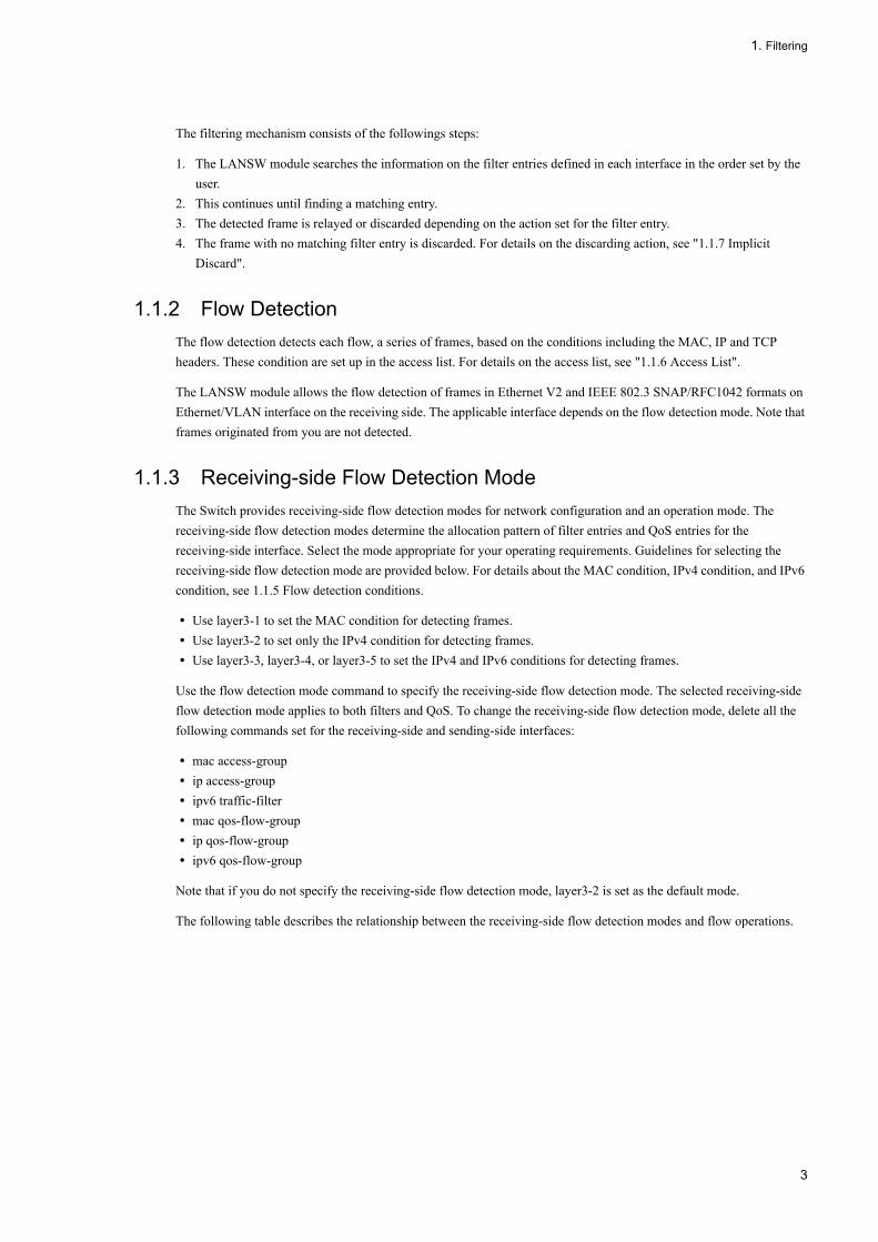
The filtering mechanism consists of the followings steps:
1. The LANSW module searches the information on the filter entries defined in each interface in the order set by the user.
2. This continues until finding a matching entry.3. The detected frame is relayed or discarded depending on the action set for the filter entry.4. The frame with no matching filter entry is discarded. For details on the discarding action, see "1.1.7 Implicit
Discard".
1.1.2 Flow DetectionThe flow detection detects each flow, a series of frames, based on the conditions including the MAC, IP and TCP headers. These condition are set up in the access list. For details on the access list, see "1.1.6 Access List".
The LANSW module allows the flow detection of frames in Ethernet V2 and IEEE 802.3 SNAP/RFC1042 formats on Ethernet/VLAN interface on the receiving side. The applicable interface depends on the flow detection mode. Note that frames originated from you are not detected.
1.1.3 Receiving-side Flow Detection ModeThe Switch provides receiving-side flow detection modes for network configuration and an operation mode. The receiving-side flow detection modes determine the allocation pattern of filter entries and QoS entries for the receiving-side interface. Select the mode appropriate for your operating requirements. Guidelines for selecting the receiving-side flow detection mode are provided below. For details about the MAC condition, IPv4 condition, and IPv6 condition, see 1.1.5 Flow detection conditions.
• Use layer3-1 to set the MAC condition for detecting frames.• Use layer3-2 to set only the IPv4 condition for detecting frames.• Use layer3-3, layer3-4, or layer3-5 to set the IPv4 and IPv6 conditions for detecting frames.
Use the flow detection mode command to specify the receiving-side flow detection mode. The selected receiving-side flow detection mode applies to both filters and QoS. To change the receiving-side flow detection mode, delete all the following commands set for the receiving-side and sending-side interfaces:
• mac access-group• ip access-group• ipv6 traffic-filter• mac qos-flow-group• ip qos-flow-group• ipv6 qos-flow-group
Note that if you do not specify the receiving-side flow detection mode, layer3-2 is set as the default mode.
The following table describes the relationship between the receiving-side flow detection modes and flow operations.
3

1. Filtering
Table 1-2: Flow detection modes for the receiving side and flow operations
1.1.4 Sending-side Flow Detection Mode The Switch provides sending-side flow detection modes for network configuration and an operation mode. The sending-side flow detection modes determine the allocation pattern of filter entries for the sending-side interface. Select the mode appropriate for your operating requirements. Guidelines for selecting the sending-side flow detection mode are provided below. For details about the MAC condition and IPv4 condition, see 1.1.5 Flow detection conditions.
• Use layer3-1-out to set only the IPv4 condition for detecting frames.• Use either layer3-2-out or layer3-3-out to set the MAC condition, IPv4 condition, and IPv6 condition for detecting
frames.
Use the flow detection out mode command to specify the sending-side flow detection mode. The selected sending-side flow detection mode takes effect on the filter. To change the sending-side flow detection mode, you need to delete all the following commands set for the receiving-side and sending-side interfaces:
• mac access-group• ip access-group
Receiving-sideFlow detection
mode name
Purpose Flow operations ApplicableInterface
layer3-1 Use this mode to perform flow controlfor IP packets and other frames. Thismode can also be used to perform flowcontrol specialized for IPv4 packets.
Frames for IP packets and otherframes are detected based on theMAC header that contains aMAC address and Ethernet type.IP packets are also detectedbased on the IP header, TCP/UDP header, and ICMP header.
Ethernet, VLAN
layer3-2 Use this mode to perform flow controlspecialized for IPv4 packets.
For IPv4 packets, frames aredetected based on the IP header,TCP/UDP header, and ICMPheader.
Ethernet
layer3-3 Use this mode to perform flow controlspecialized for IPv4 and IPv6 packets.
For IPv4 packets, frames aredetected based on the IP header,TCP/UDP header, and ICMPheader.For IPv6 packets, frames aredetected based on the sender's IPaddress.
Ethernet
layer3-4 Use this mode to perform flow controlspecialized for IPv4 and IPv6 packets.
For IPv4 packets, frames aredetected based on the IP header,TCP/UDP header, and ICMPheader.For IPv6 packets, frames aredetected based on thedestination IP address.
Ethernet
layer3-5 Use this mode to perform flow controlspecialized for IPv4 and IPv6 packets.
For IPv4 packets, frames aredetected based on the IP header,TCP/UDP header, and ICMPheader.For IPv6 packets, frames aredetected based on the IP header,TCP/UDP header, and ICMPheader.An IP address can be detected onboth the sender and destination.
Ethernet
4

1. Filtering
• ipv6 traffic-filter
If you do not specify the sending-side flow detection mode, layer3-1-out is set as the default mode. You can use layer3-3-out when VLAN tunneling is not set for the switch.
The following table describes the relationship between the sending-side flow detection modes and flow operations.
Table 1-3: Flow detection modes for the sending side and flow operations
1.1.5 Flow detection conditionsTo perform flow detection, specify the conditions for identifying the flow in the configuration. The following describes the flow detection conditions for the receiving-side and sending-side interfaces.
(1) Flow detection conditions for the receiving-side interface
The flow detection conditions for the receiving-side interface depend on the receiving-side flow detection mode.
The following table describes the flow detection conditions that can be specified for each receiving-side flow detection mode.
Table 1-4: Flow detection conditions that can be specified for the receiving-side interface (1/2)
Sending-side flow detection mode name
Purpose Flow operations ApplicableInterface
layer3-1-out Use this mode to perform flowcontrol specialized for IPv4packets.
For IPv4 packets, frames aredetected based on the IPheader, TCP/UDP header, andICMP header.
Ethernet
layer3-2-out Use this mode to perform flowcontrol for IPv4 or IPv6 packetsand other frames.
Frames for IPv4 and IPv6packets and other frames aredetected based on the MACheader that contains a MACaddress and Ethernet type.IP packets are also detectedbased on the IP header andTCP/UDP header and ICMPheader.
Ethernet
layer3-3-out Use this mode to perform flowcontrol for IPv4 or IPv6 packetsand other frames.
Frames for IPv4 and IPv6packets and other frames aredetected based on the MACheader that contains a MACaddress and Ethernet type.IP packets are also detectedbased on the IP header andTCP/UDP header and ICMPheader.
VLAN
Type Configuration items layer3-1 layer3-2
Ethernet VLAN Ethernet
MACconditions
Configuration VLAN ID#1 Y -- --
MAC header Source MAC address Y Y --
Destination MAC address Y Y --
Ethernet type Y Y --
5

1. Filtering
User priority#2 Y Y --
IPv4conditions
Configuration VLAN ID#1 Y -- Y
MAC header User priority#2 Y Y Y
IPv4 header#3 Upper-layer protocol Y Y Y
Source IP address Y Y Y
Destination IP address Y Y Y
ToS Y Y Y
DSCP Y Y Y
Precedence Y Y Y
IPv4-TCP header Source portnumber
Singlespecification(eq)
Y Y Y
Rangespecification(range)
Y#5 Y#5 Y#5
Destinationport number
Singlespecification(eq)
Y Y Y
Rangespecification(range)
Y#5 Y#5 Y#5
TCP control flag#4 Y Y Y
IPv4-UDP header Source portnumber
Singlespecification(eq)
Y Y Y
Rangespecification(range)
Y#5 Y#5 Y#5
Destinationport number
Singlespecification(eq)
Y Y Y
Rangespecification(range)
Y#5 Y#5 Y#5
IPv6conditions
Configuration VLAN ID#1 -- -- --
MAC header User priority#2 -- -- --
IPv6 header#6 Upper-layer protocol -- -- --
Source IP address -- -- --
Destination IP address -- -- --
Traffic class -- -- --
Type Configuration items layer3-1 layer3-2
Ethernet VLAN Ethernet
6

1. Filtering
Table 1-5: Flow detection conditions that can be specified for the receiving-side interface (2/2)
DSCP -- -- --
IPv6-TCP header Source portnumber
Singlespecification(eq)
-- -- --
Rangespecification(range)
-- -- --
Destinationport number
Singlespecification(eq)
-- -- --
Rangespecification(range)
-- -- --
TCP control flag#4 -- -- --
IPv6-UDP header Source portnumber
Singlespecification(eq)
-- -- --
Rangespecification(range)
-- -- --
Destinationport number
Singlespecification(eq)
-- -- --
Rangespecification(range)
-- -- --
Type Configuration items layer3-3 layer3-4 layer3-5
Ethernet Ethernet Ethernet
MACconditions
Configuration VLAN ID#1 -- -- --
MAC header Source MAC address -- -- --
Destination MAC address -- -- --
Ethernet type -- -- --
User priority#2 -- -- --
IPv4conditions
Configuration VLAN ID#1 Y Y Y
MAC header User priority#2 Y Y Y
IPv4 header#3 Upper-layer protocol Y Y Y
Source IP address Y Y Y
Destination IP address Y Y Y
Type Configuration items layer3-1 layer3-2
Ethernet VLAN Ethernet
7

1. Filtering
ToS Y Y Y
DSCP Y Y Y
Precedence Y Y Y
IPv4-TCP header Source portnumber
Singlespecification(eq)
Y Y Y
Rangespecification(range)
Y#5 Y#5 Y#5
Destinationport number
Singlespecification(eq)
Y Y Y
Rangespecification(range)
Y#5 Y#5 Y#5
TCP control flag#4 Y Y Y
IPv4-UDP header Source portnumber
Singlespecification(eq)
Y Y Y
Rangespecification(range)
Y#5 Y#5 Y#5
Destinationport number
Singlespecification(eq)
Y Y Y
Rangespecification(range)
Y#5 Y#5 Y#5
IPv6conditions
Configuration VLAN ID#1 Y Y Y
MAC header User priority#2 Y Y Y
IPv6 header#6 Upper-layer protocol -- -- Y
Source IP address Y -- Y
Destination IP address -- Y Y
Traffic class -- -- Y
DSCP -- -- Y
IPv6-TCP header Source portnumber
Singlespecification(eq)
-- -- Y
Rangespecification(range)
-- -- Y#5
Type Configuration items layer3-3 layer3-4 layer3-5
Ethernet Ethernet Ethernet
8

1. Filtering
(Legend) Y: Can be specified -: Cannot be specified
#1
VLAN IDs that can be detected by flow detection on the Switch are the values assigned to the VLANs entered in the VLAN configuration. The ID of the VLAN to which received frames belong will be detected.
#2
The user priority cannot be detected for the following frames, and therefore user priority 3 is always detected:
- Frames that do not have a VLAN tag
- Frames received on ports on which VLAN tunneling is set
- Frames whose tag has been converted
The user priority for a frame that has multiple VLAN tags is detected by counting from the MAC address side. The first VLAN tag encountered will be detected. The following figure shows an example of a frame that has multiple VLAN tags.
#3
Supplementary note for the ToS field specification
ToS: Value of bits 3 to 6 in the ToS field.
Precedence: Value of the three highest-order bits in the ToS field.
DSCP: Value of the six highest-order bits in the ToS field.
Destinationport number
Singlespecification(eq)
-- -- Y
Rangespecification(range)
-- -- Y#5
TCP control flag#4 -- -- Y
IPv6-UDP header Source portnumber
Singlespecification(eq)
-- -- Y
Rangespecification(range)
-- -- Y#5
Destinationport number
Singlespecification(eq)
-- -- Y
Rangespecification(range)
-- -- Y#5
Type Configuration items layer3-3 layer3-4 layer3-5
Ethernet Ethernet Ethernet
9

1. Filtering
#4
Packets whose ack, fin, psh, rst, syn, or urg flag is set to 1 are detected.
#5
For details about the capacity limits for the TCP or UDP port detection patterns, see 2.2(8) Filters and QoS in the manual Configuration Guide Vol. 1.
(2) Flow detection conditions for the sending-side interface
The flow detection conditions for the sending-side interface depend on the sending-side flow detection mode. The following table describes the flow detection conditions that can be specified for each sending-side flow detection mode.
Table 1-6: Flow detection conditions that can be specified for the sending-side interface
Type Configuration items layer3-1-out
layer3-2-out
layer3-3-out
Ethernet Ethernet VLAN#5
MAC conditions
Configuration VLAN ID#1 -- Y --
MAC header Source MAC address -- Y Y
Destination MAC address -- Y Y
Ethernet type -- Y Y
User priority#2 -- Y Y
IPv4 conditions
Configuration VLAN ID#1 Y Y --
MAC header User priority#2 Y Y Y
IPv4 header#3 Upper-layer protocol Y Y Y
Source IP address Y Y Y
Destination IP address Y Y Y
ToS Y Y Y
DSCP Y Y Y
Precedence Y Y Y
IPv4-TCP header Source port number
Single specification (eq)
Y Y Y
Range specification (range)
-- -- --
Destination port number
Single specification (eq)
Y Y Y
Range specification (range)
-- -- --
10

1. Filtering
TCP control flag#4 Y Y Y
IPv4-UDP header Source port number
Single specification (eq)
Y Y Y
Range specification (range)
-- -- --
Destination port number
Single specification (eq)
Y Y Y
Range specification (range)
-- -- --
IPv6 conditions
Configuration VLAN ID -- Y --
MAC header User priority -- Y Y
IPv6 header Upper-layer protocol -- Y Y
Source IP address -- Y Y
Destination IP address -- Y Y
Traffic class -- Y Y
DSCP -- Y Y
IPv6-TCP header Source port number
Single specification (eq)
-- Y Y
Range specification (range)
-- -- --
Destination port number
Single specification (eq)
-- Y Y
Range specification (range)
-- -- --
TCP control flag#4 -- Y Y
IPv6-UDP header Source port number
Single specification (eq)
-- Y Y
Rangespecification(range)
-- -- --
Destinationport number
Singlespecification(eq)
-- Y Y
Type Configuration items layer3-1-out
layer3-2-out
layer3-3-out
Ethernet Ethernet VLAN#5
11

1. Filtering
Legend: Y: Can be specified, --: Cannot be specified
#1
VLAN IDs that can be detected by flow detection on the Switch are the values assigned to the VLANs entered in the VLAN configuration. The ID of the VLAN to which the outgoing frames belong will be detected.
You cannot specify a VLAN ID for either of the following interfaces:
- Ethernet interfaces for which tag translation is set
- Ethernet interfaces for which VLAN tunneling is set
#2
The user priority set in the VLAN tag of the send frame is detected. The user priority for a frame that has multiple VLAN tags is detected by counting from the MAC address side. The first VLAN tag encountered will be detected. The following figure shows an example of a frame that has multiple VLAN tags.
For the sending-side interface, the user priority for a frame without a VLAN tag is also detected. The following table describes the details of user priority detection.
Table 1-7: User priority detection on the sending-side interface
Rangespecification(range)
-- -- --
Ports from which frames are sent
Sendingframe
Flow detection operation for detecting the user priority
Ports for which VLAN tunneling is not set
-- If the marking functionality is used on the receiving side, the user priority after marking is performed is detected.If the marking functionality is not used on the receiving side and frames without VLAN tag are received, user priority 3 is detected.If the marking functionality is not used on the receiving side and frames with VLAN tag are received, the user priority that exists when the frames are received is detected. Note, however, that user priority 3 is detected for the following frames:Frames received on ports on which VLAN tunneling is setFrames whose tag has been converted
Ports for which VLAN tunneling is set
Without VLAN tag
Same as above
With VLAN tag
The user priority for send frames is detected as follows, regardless of whether the marking functionality is used on the receiving side. The following user priority is detected for the outgoing frames:For frames received on a port for which VLAN tunneling is set, the user priority that exists when the frames are received is detected.For frames received on a port for which VLAN tunneling is not set, the user priority that exists when VLAN tags are removed from the receive frames is detected.
Type Configuration items layer3-1-out
layer3-2-out
layer3-3-out
Ethernet Ethernet VLAN#5
12

1. Filtering
Legend --: With or without a VLAN tag
#3
Supplementary note for the ToS field specification
ToS: Value of bits 3 to 6 in the ToS field.
Precedence: Value of the three highest-order bits in the ToS field.
DSCP: Value of the six highest-order bits in the ToS field.
When the marking functionality is used to update a DSCP on the receiving-side interface, the values of ToS, DSCP, and Precedence for the sending-side interface are detected for the frames after the DSCP is updated.
#4
Packets whose ack, fin, psh, rst, syn, or urg flag is set to 1 are detected.
#5
Filter entries are not applicable for the following VLAN interface:
- Tag translation is set for at least one of the Ethernet interfaces that belong to the VLAN.
1.1.6 Access ListYou must set up an access list in the configuration to perform a flow detection by filtering. The access list differs for each flow detection condition. The frame type that can be detected also depends on the flow detection condition. The following table lists the relationships between flow detection conditions and their associated access lists, as well as detectable frame types.
Table 1-8: Flow Detection Condition and Corresponding Access List and Applicable Frame Type
(Legend) Y: Can be detected -: Cannot be detected
The order to apply the filter entries is determined by the sequence number which is a parameter of access list. Retrieving the filter entries is independently carried out by access list. Thus, a frame can match with more than one filter entry. If this happens, only a single filter entry can become active.
(1) Actions when a frame matches both of Ethernet and VLAN interface entries
(a)For the receiving-side interface
When you set filter entries for an Ethernet interface and the VLAN interface to which the Ethernet interface belongs to filter frames received from the Ethernet interface, a frame might match multiple filter entries. In
Available Flow Detection Conditions
Access List Corresponding Flow Detection Mode
Detectable Frame Type
Non-IP IPv4 IPv6
MAC condition mac access-list layer3-1 Y Y Y
IPv4 condition access-listip access-list
layer3-1,layer3-2,layer3-3,layer3-4
- Y -
IPv6 condition ipv6 access-list layer3-3,layer3-4
- - Y
13
1. Filtering
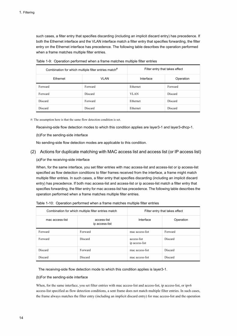
such cases, a filter entry that specifies discarding (including an implicit discard entry) has precedence. If both the Ethernet interface and the VLAN interface match a filter entry that specifies forwarding, the filter entry on the Ethernet interface has precedence. The following table describes the operation performed when a frame matches multiple filter entries.
Table 1-9: Operation performed when a frame matches multiple filter entries
#: The assumption here is that the same flow detection condition is set.
Receiving-side flow detection modes to which this condition applies are layer3-1 and layer3-dhcp-1.
(b)For the sending-side interface
No sending-side flow detection modes are applicable to this condition.
(2) Actions for duplicate matching with MAC access list and access list (or IP access list)
(a)For the receiving-side interface
When, for the same interface, you set filter entries with mac access-list and access-list or ip access-list specified as flow detection conditions to filter frames received from the interface, a frame might match multiple filter entries. In such cases, a filter entry that specifies discarding (including an implicit discard entry) has precedence. If both mac access-list and access-list or ip access-list match a filter entry that specifies forwarding, the filter entry for mac access-list has precedence. The following table describes the operation performed when a frame matches multiple filter entries.
Table 1-10: Operation performed when a frame matches multiple filter entries
The receiving-side flow detection mode to which this condition applies is layer3-1.
(b)For the sending-side interface
When, for the same interface, you set filter entries with mac access-list and access-list, ip access-list, or ipv6 access-list specified as flow detection conditions, a sent frame does not match multiple filter entries. In such cases, the frame always matches the filter entry (including an implicit discard entry) for mac access-list and the operation
Combination for which multiple filter entries match# Filter entry that takes effect
Ethernet VLAN Interface Operation
Forward Forward Ethernet Forward
Forward Discard VLAN Discard
Discard Forward Ethernet Discard
Discard Discard Ethernet Discard
Combination for which multiple filter entries match Filter entry that takes effect
mac access-list access-listip access-list
Interface Operation
Forward Forward mac access-list Forward
Forward Discard access-listip access-list
Discard
Discard Forward mac access-list Discard
Discard Discard mac access-list Discard
14
1. Filtering
specified for that filter entry is performed.
Sending-side flow detection modes to which this condition applies are layer3-2-out and layer3-3-out.
The flow detection mode applicable to this condition is "layer3-1".
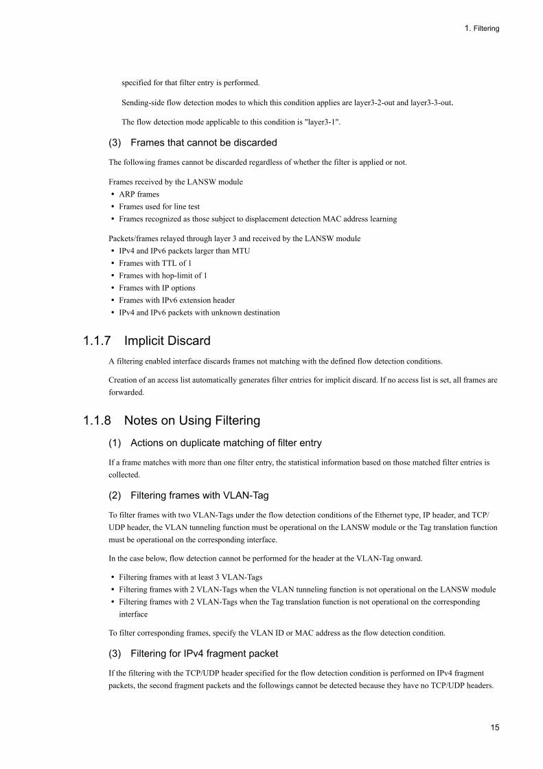
(3) Frames that cannot be discarded
The following frames cannot be discarded regardless of whether the filter is applied or not.
Frames received by the LANSW module• ARP frames• Frames used for line test• Frames recognized as those subject to displacement detection MAC address learning
Packets/frames relayed through layer 3 and received by the LANSW module• IPv4 and IPv6 packets larger than MTU• Frames with TTL of 1• Frames with hop-limit of 1• Frames with IP options• Frames with IPv6 extension header• IPv4 and IPv6 packets with unknown destination
1.1.7 Implicit DiscardA filtering enabled interface discards frames not matching with the defined flow detection conditions.
Creation of an access list automatically generates filter entries for implicit discard. If no access list is set, all frames are forwarded.
1.1.8 Notes on Using Filtering
(1) Actions on duplicate matching of filter entry
If a frame matches with more than one filter entry, the statistical information based on those matched filter entries is collected.
(2) Filtering frames with VLAN-Tag
To filter frames with two VLAN-Tags under the flow detection conditions of the Ethernet type, IP header, and TCP/UDP header, the VLAN tunneling function must be operational on the LANSW module or the Tag translation function must be operational on the corresponding interface.
In the case below, flow detection cannot be performed for the header at the VLAN-Tag onward.
• Filtering frames with at least 3 VLAN-Tags• Filtering frames with 2 VLAN-Tags when the VLAN tunneling function is not operational on the LANSW module• Filtering frames with 2 VLAN-Tags when the Tag translation function is not operational on the corresponding
interface
To filter corresponding frames, specify the VLAN ID or MAC address as the flow detection condition.
(3) Filtering for IPv4 fragment packet
If the filtering with the TCP/UDP header specified for the flow detection condition is performed on IPv4 fragment packets, the second fragment packets and the followings cannot be detected because they have no TCP/UDP headers.
15

1. Filtering
When filtering packets including fragment packets, specify the MAC and IP headers for the flow detection conditions.
(4) Filter for the IPv6 packet having the extended header
The filter cannot be executed for which the TCP/UDP header is defined as the flow detection condition for the IPv6 packet having the IPv6 extended header. To execute the filter for the packet having the extended header, specify the MAC and IPv6 headers for the flow detection condition.
(5) Actions when applying filter entries
The LANSW module applies the implicit discard entries first when applying filters to an interface*. This means that any frames matching with the implicit discard are discarded temporarily until a user-defined filter entry is applied. The statistical information on implicit discard entries is also collected.
*• When applying an access list with 1 or more entry to an interface by the access group commands.• Where the access group command apples the access list and adds the first entry.
(6) Operation at filter entry change
In this device, if the filter entry already applied to the interface has been changed, the frame to be detected is not detected until the interface change is reflected. Therefore, the frame is temporarily detected for another filter entry or implicit discard entry.
(7) Interruption by another function
In the following conditions, frames are discarded. However, if filter entries have been set up for the interface and there is a match, the statistical information on the matched filter entry is collected.
• When the data transfer status of VLAN port is "Blocking" (data transfer stopped), and a frame is received from the port.
• When a VLAN-Tagged frame is received on the protocol VLAN/MAC VLAN.• When a frame is received from the port specified with the inter-port relay blocking function.• When a frame with no VLAN-Tag is received with the native VLAN which is not set to the VLAN sending/receiving
via trunk port.• When a VLAN-Tagged frame is received with the VLAN which is not set to send/receive via trunk port.
16

1. Filtering
1.2 Configuration
1.2.1 List of Configuration CommandsThe following table lists the configuration commands used for the filtering:
Table 1-11: List of Configuration Commands
* Except for the LAN switch module of Compute Blade 320
1.2.2 Setting the Receiving-side Flow Detection ModeThe following procedure is an example of setting up the receiving-side flow detection mode for the filtering:
[Point of setting]The flow detection mode must be set first, since it determines the basic operating condition for the hardware.
[Setup using commands]
1. (config)# flow detection mode layer3-3
Enables receiving-side flow detection mode layer3-3.
1.2.3 Setting the Sending-side Flow Detection ModeThe following procedure is an example of setting up the sending-side flow detection mode for the filtering:
* This setting can not be in the LAN switch module for Compute Blade 320.
[Point of setting]
Command Description
access-list Sets access list that functions as IPv4 packet filtering.
deny Defines the conditions for canceling accesses through an IPv4 filter.
flow detection mode Sets up the flow detection mode for filtering and QoS control.
ip access-group Applies an IPv4 filter to an Ethernet or VLAN interface to enable the IPv4 filter.
ip access-list extended Sets up the access list that operates as an IPv4 packet filtering.
ip access-list resequence Resets the sequence number of filter condition application order for IPv4 address filter and IPv4 packet filter.
ip access-list standard Sets access list that functions as IPv4 address filter.
ipv6 access-list Sets access list that functions as IPv6 filter.
ipv6 access-list resequence Resets the sequence number to apply the IPv6 filtering condition.
ipv6 traffic-filter Applies an IPv6 filter to an Ethernet to enable the IPv6 filter.
mac access-group Applies a MAC filter to an Ethernet or VLAN interface to enable the MAC filter.
mac access-list resequence Resets the sequence number to apply the MAC filtering conditions.
mac access-list extended Sets an access list that operates as a MAC filter.
permit Specifies the conditions for relaying accesses through an IPv4 filter.
remark Sets up supplementary descriptions for a filter.
flow detection out mode* Sets the sending-side flow detection mode for the filter.
17
1. Filtering
The flow detection mode must be set first, since it determines the basic operating condition for the hardware.
[Setup using commands]
1. (config)# flow detection out mode layer3-2-out
Enables sending-side flow detection mode layer3-2-out.
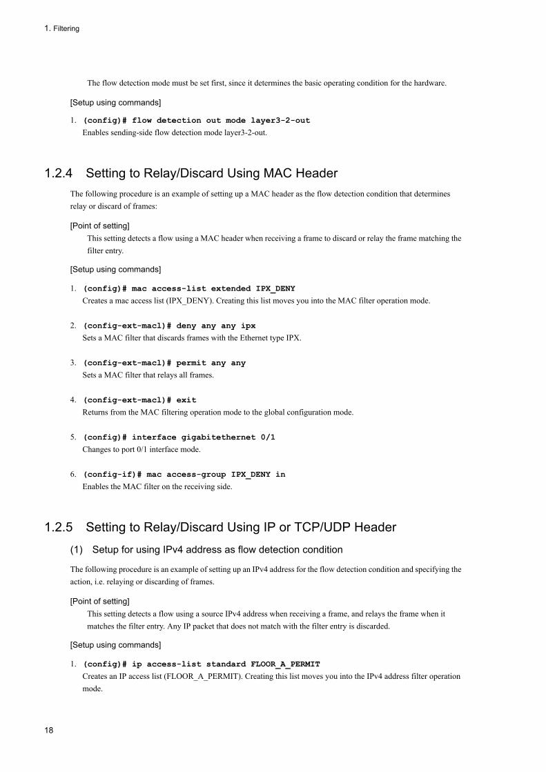
1.2.4 Setting to Relay/Discard Using MAC HeaderThe following procedure is an example of setting up a MAC header as the flow detection condition that determines relay or discard of frames:
[Point of setting]This setting detects a flow using a MAC header when receiving a frame to discard or relay the frame matching the filter entry.
[Setup using commands]
1. (config)# mac access-list extended IPX_DENY
Creates a mac access list (IPX_DENY). Creating this list moves you into the MAC filter operation mode.
2. (config-ext-macl)# deny any any ipx
Sets a MAC filter that discards frames with the Ethernet type IPX.
3. (config-ext-macl)# permit any any
Sets a MAC filter that relays all frames.
4. (config-ext-macl)# exit
Returns from the MAC filtering operation mode to the global configuration mode.
5. (config)# interface gigabitethernet 0/1
Changes to port 0/1 interface mode.
6. (config-if)# mac access-group IPX_DENY in
Enables the MAC filter on the receiving side.
1.2.5 Setting to Relay/Discard Using IP or TCP/UDP Header
(1) Setup for using IPv4 address as flow detection condition
The following procedure is an example of setting up an IPv4 address for the flow detection condition and specifying the action, i.e. relaying or discarding of frames.
[Point of setting]This setting detects a flow using a source IPv4 address when receiving a frame, and relays the frame when it matches the filter entry. Any IP packet that does not match with the filter entry is discarded.
[Setup using commands]
1. (config)# ip access-list standard FLOOR_A_PERMIT
Creates an IP access list (FLOOR_A_PERMIT). Creating this list moves you into the IPv4 address filter operation mode.
18
1. Filtering
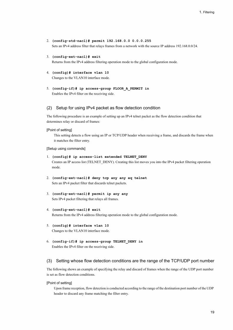
2. (config-std-nacl)# permit 192.168.0.0 0.0.0.255
Sets an IPv4 address filter that relays frames from a network with the source IP address 192.168.0.0/24.
3. (config-ext-nacl)# exit
Returns from the IPv4 address filtering operation mode to the global configuration mode.
4. (config)# interface vlan 10
Changes to the VLAN10 interface mode.
5. (config-if)# ip access-group FLOOR_A_PERMIT in
Enables the IPv4 filter on the receiving side.
(2) Setup for using IPv4 packet as flow detection condition
The following procedure is an example of setting up an IPv4 telnet packet as the flow detection condition that determines relay or discard of frames:
[Point of setting]This setting detects a flow using an IP or TCP/UDP header when receiving a frame, and discards the frame when it matches the filter entry.
[Setup using commands]
1. (config)# ip access-list extended TELNET_DENY
Creates an IP access list (TELNET_DENY). Creating this list moves you into the IPv4 packet filtering operation mode.
2. (config-ext-nacl)# deny tcp any any eq telnet
Sets an IPv4 packet filter that discards telnet packets.
3. (config-ext-nacl)# permit ip any any
Sets IPv4 packet filtering that relays all frames.
4. (config-ext-nacl)# exit
Returns from the IPv4 address filtering operation mode to the global configuration mode.
5. (config)# interface vlan 10
Changes to the VLAN10 interface mode.
6. (config-if)# ip access-group TELNET_DENY in
Enables the IPv4 filter on the receiving side.
(3) Setting whose flow detection conditions are the range of the TCP/UDP port number
The following shows an example of specifying the relay and discard of frames when the range of the UDP port number is set as flow detection conditions.
[Point of setting]Upon frame reception, flow detection is conducted according to the range of the destination port number of the UDP header to discard any frame matching the filter entry.
19

1. Filtering
[Setup using commands]
1. (config)# ip access-list extended PORT_RANGE_DENY
This creates "ip access-list (PORT_RANGE_DENY." When this list is created, the mode moves to the IPv4 packet filter operation mode.
2. (config-ext-nacl)# deny udp any any range 10 20
This sets the IPv4 packet filter that discards the packets that are equal to 10 to 20 in terms of the destination port number of the UDP header.
3. (config-ext-nacl)# permit ip any any
This sets the IPv4 packet filter for relaying all frames.
4. (config-ext-nacl)# exit
The mode returns from the operation of the IPv4 address filter to the global configuration.
5. (config)# interface vlan 10
The mode moves to the VLAN10 interface mode.
6. (config-if)# ip access-group PORT_RANGE_DENY in
The IPv4 filter on the receive side is enabled.
(4) Setup for using IPv6 packet as flow detection condition
The following procedure is an example of setting up an IPv6 address as the flow detection condition that determines relay or discard of frames:
[Point of setting]This setting detects a flow using an IP address when receiving a frame, and relays the frame when it matches the filter entry. Any IP packet that does not match with the filter entry is discarded.
[Setup using commands]
1. (config)# ipv6 access-list FLOOR_B_PERMIT
Creates an IPv6 access list (FLOOR_B_PERMIT). Creating this list moves you into the IPv6 packet filter operation mode.
2. (config-ipv6-acl)# permit ipv6 2001:100::1/64 any
Sets an IPv6 packet filter that relays frames from source IP address 2001:100::1/64.
3. (config-ipv6-acl)# exit
Returns from the IPv6 packet filtering operation mode to the global configuration mode.
4. (config)# interface gigabitethernet 0/1
Changes to port 0/1 interface mode.
5. (config-if)# ipv6 traffic-filter FLOOR_B_PERMIT in
Enables the IPv6 filter on the receiving side.
20

1. Filtering
1.2.6 Setting Multi-Interface FilterThe following procedure is an example of setting up filters for more than one Ethernet interface:
[Point of setting]Use the config-if-range mode to set up more than one Ethernet interface filter.
[Setup using commands]
1. (config)# access-list 10 permit host 192.168.0.1
Sets the IPv4 address filter that relays frames only from host 192.168.0.1.
2. (config)# interface range gigabitethernet 0/1-4
Changes to the port 0/1-4 interface mode.
3. (config-if-range)# ip access-group 10 in
Enables the IPv4 filter on the receiving side.
21

1. Filtering
1.3 Operation
Use the "show access-filter" command to test whether the configuration is reflected to the LANSW module.
1.3.1 List of Operation CommandsThe following table lists the operation commands used for the filtering:
Table 1-12: List of Operation Commands
1.3.2 Checking Filter Operation
(1) Checking entries set up for Ethernet interface
The following image shows checking for the operation of an Ethernet interface with a filter:
Figure 1-3: Checking Operation of Ethernet Interface with a Filter
> show access-filter 0/1 IPX_DENYDate 2005/12/01 12:00:00 UTCUsing Port:0/1 inExtended MAC access-list: IPX_DENY remark "deny only ipx" deny any any ipx matched packets : 74699826 permit any any matched packets : 264176 implicitly denied packets: 0
Make sure that the specified port filter shows a response, "Extended MAC access-list".
(2) Checking entries set up for VLAN interface
The following image shows checking for the operation an VLAN interface with filter set:
Figure 1-4: Checking Operation of VLAN Interface with Filter Specified
> show access-filter interface vlan 10 FLOOR_A_PERMITDate 2005/12/01 12:00:00 UTCUsing Interface:vlan 10 inStandard IP access-list: FLOOR_A_PERMIT remark "permit only Floor-A" permit 192.168.0.0 0.0.0.255 any matched packets : 74699826 implicitly denied packets: 2698
Make sure that the specified VLAN filter shows a response, "Standard IP access-list".
Command Description
show access-filter Displays the statistics information of the access list (i.e., MAC access list, access list, IP access list or ipv6 access list) set up using the access group command (i.e., mac access-group, ip access-group or ipv6 traffic-filter).
clear access-filter Erases the statistics information of the access list (i.e., MAC access list, access list, IP access list or ipv6 access list) set up using the access group command (i.e., mac access-group, ip access-group or ipv6 traffic-filter).
22

Part 2 QoS
2 General Description of QoS ControlQoS control is a function to optimize the usage of limited network resources, such as the bandwidth of a line and the buffer capacity of a queue, by controlling the communication quality by means of bandwidth monitoring, marker, priority assignment, and bandwidth control. This chapter explains the QoS control of the LANSW module.
2.1 QoS Control Structure
2.2 Common Process Overview
2.3 Configuration Common to QoS Control
2.4 Operations Common to QoS Control
23
2. General Description of QoS Control
2.1 QoS Control Structure
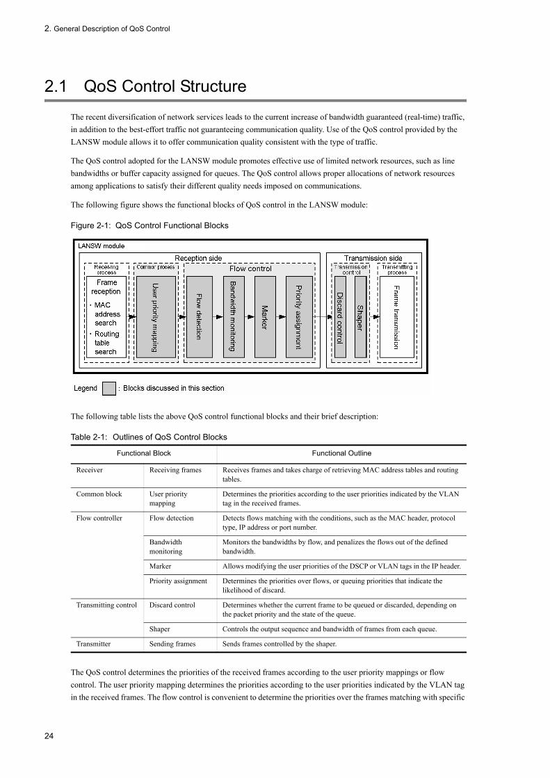
The recent diversification of network services leads to the current increase of bandwidth guaranteed (real-time) traffic, in addition to the best-effort traffic not guaranteeing communication quality. Use of the QoS control provided by the LANSW module allows it to offer communication quality consistent with the type of traffic.
The QoS control adopted for the LANSW module promotes effective use of limited network resources, such as line bandwidths or buffer capacity assigned for queues. The QoS control allows proper allocations of network resources among applications to satisfy their different quality needs imposed on communications.
The following figure shows the functional blocks of QoS control in the LANSW module:
Figure 2-1: QoS Control Functional Blocks
The following table lists the above QoS control functional blocks and their brief description:
Table 2-1: Outlines of QoS Control Blocks
The QoS control determines the priorities of the received frames according to the user priority mappings or flow control. The user priority mapping determines the priorities according to the user priorities indicated by the VLAN tag in the received frames. The flow control is convenient to determine the priorities over the frames matching with specific
Functional Block Functional Outline
Receiver Receiving frames Receives frames and takes charge of retrieving MAC address tables and routing tables.
Common block User priority mapping
Determines the priorities according to the user priorities indicated by the VLAN tag in the received frames.
Flow controller Flow detection Detects flows matching with the conditions, such as the MAC header, protocol type, IP address or port number.
Bandwidth monitoring
Monitors the bandwidths by flow, and penalizes the flows out of the defined bandwidth.
Marker Allows modifying the user priorities of the DSCP or VLAN tags in the IP header.
Priority assignment Determines the priorities over flows, or queuing priorities that indicate the likelihood of discard.
Transmitting control Discard control Determines whether the current frame to be queued or discarded, depending on the packet priority and the state of the queue.
Shaper Controls the output sequence and bandwidth of frames from each queue.
Transmitter Sending frames Sends frames controlled by the shaper.
24

2. General Description of QoS Control
conditions including MAC or IP addresses. instead of to determine the user priorities.
Determining the priorities using the flow control takes precedence over the user priority mappings. In the flow control, monitoring bandwidths and marking are available, as well as priority assignment. The monitoring bandwidths, marker, and priority assignment functions can operate on flows detected during flow detection at a time.
The transmitter performs discard control or shaper according to the priorities determined by the user priority mappings or flow controls.
25

2. General Description of QoS Control
2.2 Common Process Overview
The following figure illustrates the positioning of the user priority mappings in the QoS control, described in this subsection:
Figure 2-2: Positioning of User Priority Mapping
2.2.1 User Priority MappingThe user priority mapping determines the priorities according to the user priorities indicated by the VLAN tag in the received frames. The user priority mapping is always active to determine the priorities over the all received frames.
The CoS values, indicating the priorities in the LANSW module, are used to represent the priority values. The user priority value in a received frame is mapped to a CoS value, which determines the sequence in the sending queue. For the correspondences between the CoS values and sending queues, see "3.10.3 CoS Mapping".
The user priorities indicate the upper three bits of the tag information contained in the VLAN tag header. For frames without the VLAN tag, always CoS value 3 is used.
Where priority determination with the flow control is active, it takes precedence over the user priority mapping.
Table 2-2: User Priority and CoS Value Mapping
(Legend) -: Not applicable
Type of Frame CoS Value Mapped
Presence of VLAN Tag User Priority Value
Without VLAN tag - 3
With VLAN tag* 0 0
1 1
2 2
3 3
4 4
5 5
6 6
7 7
26

2. General Description of QoS Control
*Any frame received at the port where VLAN tunneling has been set is always mapped to a CoS value of 3, irrespective of the user priority value at the time of reception.
2.2.2 Notes on User Priority Mapping
(1) Target of user priority mapping
When forwarding frames in layer 3, the user priority mapping is valid up to two stacked VLAN tags. If a frame with a three or more stacked VLAN tag is received, it is discarded. The following figure schematically illustrates VLAN tags to which the user priority mapping is valid:
Figure 2-3: Target of User Priority Mapping
27

2. General Description of QoS Control
2.3 Configuration Common to QoS Control
2.3.1 List of Configuration CommandsThe following table lists the configuration commands common to the all QoS controls:
Table 2-3: List of Configuration Commands
Command Description
flow detection mode Sets up the flow detection mode for filtering and QoS control.
ip qos-flow-group Applies an IPv4 QoS flow list to an Ethernet or VLAN interface to enable the IPv4 QoS control.
ip qos-flow-list Sets up a QoS flow list for IPv4 QoS flow detection.
ip qos-flow-list resequence Re-sets the sequence number denoting the order of applying conditions for an IPv4 QoS flow list.
ipv6 qos-flow-group Applies an IPv6 QoS flow list to an Ethernet interface to enable the IPv6 QoS control.
ipv6 qos-flow-list Sets a QoS flow list for IPv6 QoS flow detection.
ipv6 qos-flow-list resequence Resets the sequence number denoting the order of applying conditions for an IPv6 QoS flow list.
mac qos-flow-group Applies an MAC QoS flow list to an Ethernet or VLAN interface to enable the MAC QoS control.
mac qos-flow-list Sets a QoS flow list for MAC QoS flow detection.
mac qos-flow-list resequence Resets the sequence number denoting the order of applying conditions for an MAC QoS flow list.
qos Sets the flow detection condition and actions in the QoS flow list.
qos-queue-group Applies the QoS queue list information to the Ethernet interface and enables shaping.
qos-queue-list Sets up the scheduling mode for QoS queue list information.
remark Describes supplementary descriptions for QoS.
traffic-shaper rate Sets up the port bandwidth control for an Ethernet interface.
28

2. General Description of QoS Control
2.4 Operations Common to QoS Control
2.4.1 List of Operation CommandsThe following table lists the operation commands common to the all QoS controls:
Table 2-4: List of Operation Commands
Command Description
show qos-flow Displays the statistics from the QoS flow list (i.e., MAC QOS flow list, IP QoS flow list, IPv6 QoS flow list) set up using the QoS flow group command (i.e., mac qos-flow-group, ip qos-flow-group, ipv6 qos-flow-group).
clear qos-flow Erases the statistics from the QoS flow list (i.e., MAC QoS flow list, IP QoS flow list, IPv6 QoS flow list) set up using the QoS flow group command (i.e., mac qos-flow-group, ip qos-flow-group, ipv6 qos-flow-group).
show qos queueing Displays the statistics on sending queues from an Ethernet interface.
clear qos queueing Clears the statistics on sending queues from an Ethernet interface.
29

2. General Description of QoS Control
30
3 Flow ControlThis chapter describes the flow control (flow detection, bandwidth monitoring, marker, and priority assignment) provided by the LANSW module.
3.1 Flow Detection Overview
3.2 Flow Detection Configuration
3.3 Flow Detection Operation
3.4 Bandwidth Monitoring Overview
3.5 Configuration of Bandwidth Monitoring
3.6 Operation of Bandwidth Monitoring
3.7 Marker Overview
3.8 Configuration of Marker
3.9 Operation of Marker
3.10 Priority Assignment Overview
3.11 Configuration of Priority Assignment
3.12 Operation of Priority
3.13 Actions When Multiple Matching QoS Entries are Detected
31

3. Flow Control
3.1 Flow Detection Overview
The flow detection is a function that detects the flow of a series of frames, based on various conditions, such as the MAC header, IP header and TCP header. This is set in the QoS flow list. For details of the QoS flow list, see "3.1.3 QoS Flow List".
The LANSW module allows the flow detection of frames in Ethernet V2 and IEEE 802.3 SNAP/RFC1042 formats on Ethernet/VLAN interface on the receiving side. The applicable interface depends on the flow detection mode. Note the flow detection is not applied to the frames sent by the LANSW module autonomously.
The figure below indicates the positioning of the flow detection explained in this section.
Figure 3-1: Positioning of Flow Detection
3.1.1 Receiving-side Flow Detection ModeThe LANSW module provides four flow detection modes to satisfy different network configuration and/or operation. Select the appropriate mode according to the system application. The following shows how to select the flow detection mode. For details about the MAC, IPv4, and IPv6 conditions, see Section , "3.1.2 Flow Detection Conditions".
• You should use layer3-1 when you want to detect frames under the MAC conditions.• You should use layer3-2 when you want to detect frames under the MAC conditions alone.• You should use either layer3-3 or layer3-4 when you want to detect frames under the IPv4 and IPv6.• Use layer3-dhcp-1 to set the IPv4 condition for detecting frames and to use the filtering functionality of DHCP
snooping.
The "flow detection mode" command is used to specify the receiving-side flow detection mode. The selected receiving-side flow detection mode is applied to both of the filtering and QoS functions. To change the receiving-side flow detection mode, delete all the following commands set for the receiving-side and sending-side interfaces:
• mac access-group• ip access-group• ipv6 traffic-filter• mac qos-flow-group• ip qos-flow-group• ipv6 qos-flow-group
If the flow detection mode is not specified, the mode "layer3-2" is used by default.
32

3. Flow Control
The following table describes the correlation between the receiving-side flow detection modes and flow operations.
Table 3-1: Correlation between The Receiving-side Flow Detection Mode and Flow Operation
3.1.2 Flow Detection ConditionsTo implement the flow detection, the conditions to identify each flow must be specified in the configuration. The table below shows the available flow detection conditions for each flow detection mode.
(1) Flow detection conditions for the receiving-side interface
The flow detection conditions for the receiving-side interface depend on the receiving-side flow detection mode. The following table describes the flow detection conditions that can be specified for each receiving-side flow detection mode.
Table 3-2: Available Flow Detection Conditions (1/2)
Flow Detection Mode Name
Objective Application Flow Operation Target Interface to Detect
layer3-1 Use this mode to implement the flow control on IP packets and other frames. This mode can be used also for the flow control dedicated to IPv4 packets.
Detects frames by the MAC header such as MAC address and Ethernet type.When detecting frames for IPv4 packets, the IP or TCP/UDP header is referred to for detecting their frames.
Ethernet, VLAN
layer3-2 Use this mode to implement the flow control dedicated to IPv4 packets.
For IPv4 packets, detects frames by IP header and TCP/UDP header.
Ethernet
layer3-3 Use this mode to implement the flow control dedicated to IPv4 and IPv6 packets.
When detecting frames for IPv4 packets, the IP or TCP/UDP header is referred to for detecting their frames.For IPv6 packets, detects frames by source IP address.
Ethernet
layer3-4 Use this mode to implement the flow control dedicated to IPv4 and IPv6 packets.
When detecting frames for IPv4 packets, the IP or TCP/UDP header is referred to for detecting their frames.For IPv6 packets, detects frames by destination IP address.
Ethernet
layer3-5 Use this mode to implement the flow control dedicated to IPv4 and IPv6 packets.
When detecting frames for IPv4 packets, the IP or TCP/UDP header is referred to for detecting their frames.For IPv6 packets, detects frames by TCP/UDP header.An IP address can be detected on both the sender and destination.
Ethernet
Type Setting Item layer3-1 layer3-2
Ethernet VLAN Ethernet
MAC condition
Configuration VLAN ID*1 Y - -
MAC header Source MAC address Y Y -
Destination MAC address Y Y -
Ethernet type Y Y -
User priority *2 Y Y Y
33

3. Flow Control
Table 3-3: Available Flow Detection Conditions (2/2)
IPv4 condition Configuration VLAN ID*1 Y - Y
MAC header User priority *2 Y - Y
IPv4 header*3 Upper layer protocol Y Y Y
Source IP address Y Y Y
Destination IP address Y Y Y
ToS Y Y Y
DSCP Y Y Y
Precedence Y Y Y
IPv4-TCP header Source port number Single specification(eq)
Y Y Y
Range specification(range)
Y*5 Y*5 Y*5
Source port number Single specification(eq)
Y Y Y
Range specification(range)
Y*5 Y*5 Y*5
TCP control flag *4 Y Y Y
IPv4-UDP header Source port number Single specification(eq)
Y Y Y
Range specification(range)
Y*5 Y*5 Y*5
Source port number Single specification(eq)
Y Y Y
Range specification(range)
Y*5 Y*5 Y*5
IPv6 condition Configuration VLAN ID*1 - - -
MAC header User priority *2 - - -
IPv6 header Source IP address - - -
Destination IP address - - -
Type Setting Item layer3-3 layer3-4 layer3-5
Ethernet Ethernet Ethernet
MAC condition
Configuration VLAN ID*1 - - -
MAC header Source MAC address - - -
Destination MAC address - - -
Ethernet t-pe - - -
User priority- *2 - - -
Type Setting Item layer3-1 layer3-2
Ethernet VLAN Ethernet
34

3. Flow Control
IPv4 condition Configuration VLAN ID*1 Y Y Y
MAC header User priority *2 Y Y Y
IPv4 header*3 Upper layer protocol Y Y Y
Source IP address Y Y Y
Destination IP address Y Y Y
ToS Y Y Y
DSCP Y Y Y
Precedence Y Y Y
IPv4-TCP header Source port number Single specification(eq)
Y Y Y
Range specification(range)
Y*5 Y*5 Y*5
Destination port number
Single specification(eq)
Y Y Y
Range specification(range)
Y*5 Y*5 Y*5
TCP control flag *4 Y Y Y
IPv4-UDP header Source port number Single specification(eq)
Y Y Y
Range specification(range)
Y*5 Y*5 Y*5
Destination port number
Single specification(eq)
Y Y Y
Range specification(range)
Y*5 Y*5 Y*5
Type Setting Item layer3-3 layer3-4 layer3-5
Ethernet Ethernet Ethernet
35

3. Flow Control
(Legend) Y: Can be specified -: Cannot be specified
*1The LANSW module can detect VLAN IDs that have been assigned to VLANs in the VLAN configuration. During flow detection, the VLAN IDs that belong to the incoming frames are retrieved.
*2For the following frames, you cannot detect the user priority. A user priority of 3 is always used for detection.• Frames having no VLAN tag• Frame received at the port where VLAN tunneling is set• Frame whose tag has been converted by the tag conversion function
When user priority is detected for a frame having more than one VLAN tag, the target will be the user priority at the VLAN tag in the first stage as seen from the MAC address. The following diagram shows an example of a frame having more than one VLAN tag.
IPv6 condition Configuration VLAN ID*1 Y Y Y
MAC header User priority *2 Y Y Y
IPv6 header Upper layer protocol - - Y
Source IP address Y - Y
Destination IP address - Y Y
Traffic class - - Y
DSCP - - Y
IPv6-TCP header Source port number Single specification(eq)
- - Y
Range specification(range)
- - Y*5
Destination port number
Single specification(eq)
- - Y
Range specification(range)
- - Y*5
TCP control flag *4 - - Y
IPv6-UDP header Source port number Single specification(eq)
- - Y
Range specification(range)
- - Y*5
Destination port number
Single specification(eq)
- - Y
Range specification(range)
- - Y*5
Type Setting Item layer3-3 layer3-4 layer3-5
Ethernet Ethernet Ethernet
36

3. Flow Control
*3Supplemental information on the ToS field settingToS: 3- to 6-bit value in the ToS field.Precedence: Value of upper 3 bits in the ToS field.
DSCP: Value of upper 6 bits in the ToS field.
*4Packets with the "ack/fin/psh/rst/syn/urg" flag set to 1 are detected.
*5Up to 16 patterns for detecting the TCP/UDP port number can be used. For an example of using the patterns for detecting the TCP/UDP port number, see Section "Configuration Settings, Vol. 1, 2.2 Accommodating Conditions(8) Filter & QoS".
3.1.3 QoS Flow ListTo implement the QoS flow detection, the QoS flow list must be set in the configuration. The QoS flow list to be set depends on the flow detection condition. The frame type that can be detected also depends on the flow detection condition. The table below shows each flow detection condition and its corresponding QoS flow list and detectable frame type.
Table 3-4: Flow Detection Mode and Corresponding QoS Flow List and Applicable Frame Type
(Legend) Y: Can be detected -: Cannot be detected
To apply the QoS flow lists to the interface, use the QoS flow group commands. The application order is determined by the sequence number which is a parameter of the QoS flow list. QoS entry search is independently carried out for each QoS flow list. Thus, a frame can match more than one QoS entry. In this case, only a single QoS entry make an action in the actual operation.
(1) Actions when a frame matches both of Ethernet and VLAN interface entries
If a QoS entry is set for both of the Ethernet interface and the VLAN interface that the Ethernet interface belongs to, an incoming frame may match more than one QoS entry when the QoS flow detection is carried out on the incoming frames on the Ethernet interface. In this case, the QoS entry on the Ethernet interface overrides the QoS entry on the VLAN interface. The table below shows the preferred entry when a frame matches more than one QoS entry.
Flow Detection Conditions
Corresponding QoS Flow List
Corresponding Flow Detection Mode
Detectable Frame Type
Non-IP IPv4 IPv6
MAC condition mac qos-flow-list layer3-1 Y Y Y
IPv4 condition ip qos-flow-list layer3-1,layer3-2,layer3-3,layer3-4
- Y -
IPv6 condition ipv6 qos-flow-list layer3-3,layer3-4
- - Y
37

3. Flow Control
Table 3-5: Actions When Multiple Matching QoS Entries Are Detected
(Legend) Y: Entry specified -: Entry not specified
The flow detection mode applicable to this condition is "layer3-1".
(2) Actions when a frame matches both of "mac qos-flow-list" and "ip qos-flow-list"
If both of "mac qos-flow-list" and "ip qos-flow-list" is set as the flow detection condition on the same interface, an incoming frame may match more than one QoS entry when the QoS flow detection is carried out on the incoming frames from the interface. In this case, the QoS entry of "mac qos-flow-list" overrides the QoS entry of "ip qos-flow-list". The table below shows the preferred entry when a frame matches more than one QoS entry.
Table 3-6: Actions When Multiple Matching QoS Entries Are Detected
(Legend) Y: Entry specified -: Entry not specified
The flow detection mode applicable to this condition is "layer3-1".
3.1.4 Notes on Using Flow Detection
(1) Actions when a frame matches more than one QoS entry
If a frame matches more than one QoS entry, the statistical information based on those matched QoS entries is collected.
(2) QoS flow detection for frames with VLAN-Tag
To detect QoS flow for frames with two VLAN-Tags under the flow detection conditions of the Ethernet type, IP header, and TCP/UDP header, the VLAN tunneling function must be operational on the LANSW module or the Tag translation function must be operational on the corresponding interface.
In the case below, QoS flow detection cannot be performed for the header part after the VLAN-Tag.
• Implementing QoS flow detection for frames with at least 3 VLAN-Tags• Implementing QoS flow detection for frames with 2 VLAN-Tags when the VLAN tunneling function is not
operational on the LANSW module• Implementing QoS flow detection for frames with 2 VLAN-Tags when the Tag translation function is not operational
on the corresponding interface
To detect QoS flow for the corresponding frames, specify the VLAN ID or MAC address as the flow detection
Combination Resulting in Multiple Filter Entries to Be Matched Preferred QoS Entry
Ethernet VLAN
Y - Ethernet
- Y VLAN
Y Y Ethernet
Combination Resulting in Multiple Filter Entries to Be Matched Preferred Filter Entry
mac qos-flow-list ip qos-flow-list
Y - mac qos-flow-list
- Y ip qos-flow-list
Y Y mac qos-flow-list
38

3. Flow Control
condition.
(3) QoS flow detection for IPv4 fragment packets
If the QoS flow detection for IPv4 fragment packets is implemented using the TCP/UDP header as the flow detection condition, the second and subsequent fragment packets cannot be detected since they have no TCP/UDP header in their frames. To implement the QoS flow detection for packets including fragment packets, specify the MAC header and IP header for the flow detection condition.
(4) QoS flow detection for the IPv6 packet having the extended header
Using the TCP/UDP header as the flow detection condition, the QoS flow cannot be detected for the IPv6 packet having the IPv6 extended header. To perform the QoS flow detection for the packet having the extended header, specify the MAC and IPv6 headers for the flow detection condition.
(5) Operation at QoS Entry Change
The device is already applied to the QoS interface to change the entry until that changes, it will no longer be detected in the frame to be detected.
Therefore, in addition to temporary QoS may be found in the entry.
(6) Interruption by another function
In the following conditions, frames are discarded. However, if QoS entries have been set up for the interface and there is a match, the statistical information on the matched QoS entry is collected.
• When the data transfer status of VLAN port is "Blocking" (data transfer stopped), and a frame is received from the port.
• When a VLAN-Tagged frame is received on the protocol VLAN/MAC VLAN.• When a frame is received from the port specified with the inter-port relay blocking function.• When a frame with no VLAN-Tag is received with the native VLAN which is not set to the VLAN sending/receiving
via trunk port.• When a VLAN-Tagged frame is received with the VLAN which is not set to send/receive via trunk port.• When you receive a corresponding frame to the filter entry (The entry of tacit abandonment is included) that specifies
the abandonment operation.
39

3. Flow Control
3.2 Flow Detection Configuration
3.2.1 Setting Flow Detection ModeThe following procedure is an example of specifying the flow detection mode for QoS control:
[Point of setting]The flow detection mode must be set first, since it determines the basic operating condition for the hardware.
[Setup using commands]
1. (config)# flow detection mode layer3-3
Enables the flow detection mode "layer3-3".
3.2.2 Setting QoS Control for Multiple InterfacesThe following procedure is an example of specifying the QoS control for multiple Ethernet interfaces:
[Point of setting]To set the QoS control on more than one Ethernet interface, use "config-if-range" to enable the QoS control. .
[Setup using commands]
1. (config)# ip qos-flow-list QOS-LIST1
Creates an IPv4 QoS flow list (QOS-LIST1). Creating this list moves you into the IPv4 QoS flow list mode.
2. (config-ip-qos)# qos ip any host 192.168.100.10 action cos 6
Sets the QoS flow list with the destination address "192.168.100.10" and CoS value of 6.
3. (config-ip-qos)#exit
Returns from the IPv4 QoS flow list mode to the global configuration mode.
4. (config)# interface range gigabitethernet 0/1-4
Changes to the port 0/1-4 interface mode.
5. (config-if-range)# ip qos-flow-group QOS-LIST1 in
Enables the IPv4 QoS flow list on the receiving side.
3.2.3 Setting for Controlling QoS in the Range of the TCP/UDP Port Number
The following shows an example of specifying QoS control when the range of the UDP port number is set as the flow detection conditions.
[Point of setting]Upon frame reception, flow detection is conducted according to the range of the destination port number of the UDP header to perform QoS control. .
[Setup using commands]
1. (config)# ip qos-flow-list QOS-LIST1
Creates an IPv4 QoS flow list (QOS-LIST1). Creating this list moves you into the IPv4 QoS flow list mode.
40

3. Flow Control
2. (config-ip-qos)# qos udp any any range 10 20 action cos 6
This sets the QoS flow list with a CoS value of 6 where the range of the destination port number of the UDP header is from 10 20 as the flow detection conditions.
3. (config-ip-qos)#exit
Returns from the IPv4 QoS flow list mode to the global configuration mode.
4. (config)# interface gigabitethernet 0/1
Changes to the port 0/1 interface mode.
5. (config-if)# ip qos-flow-group QOS-LIST1 in
Enables the IPv4 QoS flow list on the receiving side.
41
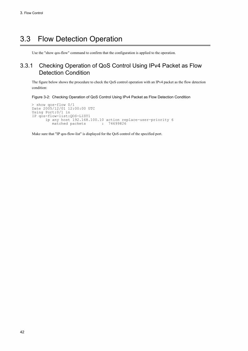
3. Flow Control
3.3 Flow Detection Operation
Use the "show qos-flow" command to confirm that the configuration is applied to the operation.
3.3.1 Checking Operation of QoS Control Using IPv4 Packet as Flow Detection Condition
The figure below shows the procedure to check the QoS control operation with an IPv4 packet as the flow detection condition:
Figure 3-2: Checking Operation of QoS Control Using IPv4 Packet as Flow Detection Condition
> show qos-flow 0/1Date 2005/12/01 12:00:00 UTCUsing Port:0/1 inIP qos-flow-list:QOS-LIST1 ip any host 192.168.100.10 action replace-user-priority 6 matched packets : 74699826
Make sure that "IP qos-flow-list" is displayed for the QoS control of the specified port.
42

3. Flow Control
3.4 Bandwidth Monitoring Overview
The bandwidth monitoring is a function to monitor the bandwidth of a flow detected by the flow detection function. The figure below indicates the positioning of the bandwidth monitoring explained in this section.
Figure 3-3: Positioning of Bandwidth Monitoring
3.4.1 Bandwidth MonitoringThis function monitors the flow bandwidth based on the received frame length (from MAC address to FCS) of the frame detected during the flow detection. Frames relayed within the designated bandwidth are referred to as "Compliant frames", and frames exceeding the bandwidth and being penalized are referred to as "Illegal frames".
To determine whether received frames are compliant with the designated bandwidth or not, "Leaky Bucket algorithm" modeling a water-filled bucket with a hole at its bottom is used.
The figure below shows a model of Leaky Bucket algorithm.
Figure 3-4: Model of Leaky Bucket Algorithm
The bucket releases water of a volume equivalent to the designated bandwidth, and new water of a volume equivalent to the size between MAC address to FCS is poured into when receiving a frame. Unless the bucket is overflowing while pouring water, the frame is assumed compliant and forwarded (as shown in the figure left). When the bucket is overflowing while pouring water, the receiving frame is determined as illegal and a penalty to discard the illegal
43

3. Flow Control
packets is imposed (as shown in the figure right). The amount of water that is allowed when a large volume of water is poured momentarily, which is the depth of the bucket, corresponds to the burst size.
Although the default burst size is 16kbyte, set a larger buffer size to relay packets in the traffic with a larger fluctuation of the bandwidth.
This feature consists of two functions; the minimum bandwidth monitoring and the maximum bandwidth control. The types of penalty available for these functions are shown in the table below.
Table 3-7: Penalty Types Available for Minimum Bandwidth Monitoring and Maximum Bandwidth Monitoring
(Legend) Y: Available penalty -: Unavailable penalty
3.4.2 Statistical Information Available for Bandwidth MonitoringThe statistical information that can be collected depends on the type of bandwidth monitoring. The table below shows the statistical information that can be collected during bandwidth monitoring:
Table 3-8: Statistical Information Available for Bandwidth Monitoring
(Legend) Y: Available -: Unavailable
3.4.3 Notes on Using Bandwidth Monitoring Function
(1) Correlation between the bandwidth designated for flows and output line and queue
If the bandwidth monitoring function is used for more than one flow, adjust each designated bandwidth value so that the total of the values of bandwidth designated for each flow is within the bandwidth value of output Ethernet interface or output queue.
(2) Co-existence with flows not subject to the bandwidth monitoring
Make sure that flows subject to the bandwidth monitoring function and those not subject to it are not output to the same line or queue.
Penalty for Illegal Frames Bandwidth Monitoring Type
Minimum Bandwidth Monitoring
Maximum Bandwidth Monitoring
Discard - Y
Change the queueing priority Y -
Rewrite DSCP Y -
Bandwidth Monitoring Type Available Statistical Information
Violation of Maximum Bandwidth
Compliance with Maximum Bandwidth
Violation of Minimum
Bandwidth
Compliance with Minimum
Bandwidth
Minimum bandwidth monitoring
- - Y Y
Maximum bandwidth monitoring
Y Y - -
Combinations of minimum and maximum bandwidth monitoring
Y Y - -
44

3. Flow Control
(3) Bandwidth monitoring for protocol control frames
Any protocol control frames terminating at the LANSW module are also subject to bandwidth monitoring. This implies they can be discarded if they are determined as illegal frames for maximum bandwidth control. To avoid this, the maximum bandwidth must be assured substantially considering the incoming protocol control frames.
(4) Using the maximum bandwidth control for TCP frames
The use of the maximum bandwidth control causes the TCP to repeat slow start, which may extremely slows down the data transmission speed.
To avoid this, use the minimum bandwidth monitoring to implement the action, "Lower the priority of their queueing so that frames can easily be discarded". With this setting, frames will not be discarded immediately, even if the subscribed bandwidth is surpassed, but discarded only when the output line becomes congested.
(5) Operation simultaneously with other functions
In the following cases, it becomes a band watch object though the frame is abandoned.
• When you receive a corresponding frame to the filter entry (The entry of tacit abandonment is included) that specifies the abandonment operation
45

3. Flow Control
3.5 Configuration of Bandwidth Monitoring
3.5.1 Setting Maximum Bandwidth Control[Point of setting]
This setting detects a flow using the destination IP address when receiving a flow, and sets the bandwidth monitoring for the maximum bandwidth control.
[Setup using commands]
1. (config)#ip qos-flow-list QOS-LIST1
Creates an IPv4 QoS flow list (QOS-LIST1). Creating this list moves you into the IPv4 QoS flow list mode.
2. (config-ip-qos)#qos ip any host 192.168.100.10 action max-rate 5M
max-rate-burst 512
Sets the IPv4 QoS flow list with the designated bandwidth for the maximum bandwidth control of 5Mbit/s, and the associated burst size of 512kbyte for flows with the destination IP address 192.168.100.10.
3. (config-ip-qos)#exit
Returns from the IPv4 QoS flow list mode to the global configuration mode.
4. (config)#interface gigabitethernet 0/1
Changes to port 0/1 interface mode.
5. (config-if)#ip qos-flow-group QOS-LIST1 in
Enables the IPv4 QoS flow list, QOS-LIST1, on the receiving side.
3.5.2 Setting Queueing Priorities on Violation at Minimum Bandwidth Monitoring
[Point of setting]This setting detects a flow using the destination IP address when receiving a frame, and sets the minimum bandwidth monitoring to be provided. For the frame violating the maximum bandwidth monitoring, its queueing priority is changed.
[Setup using commands]
1. (config)#ip qos-flow-list QOS-LIST2
Creates the IPv4 QoS flow list, QOS-LIST2. Creating this list moves you into the IPv4 QoS flow list mode.
2. (config-ip-qos)#qos ip any host 192.168.110.10 action min-rate 1M
min-rate-burst 64 penalty-discard-class 1
Sets the IPv4 QoS flow list with the designated minimum bandwidth of 1Mbit/s, the associated burst size of 64kbyte, and the queueing priority of illegal frame of 1 for flows with the destination IP address 192.168.110.10.
3. (config-ip-qos)#exit
Returns from the IPv4 QoS flow list mode to the global configuration mode.
4. (config)#interface gigabitethernet 0/3
46
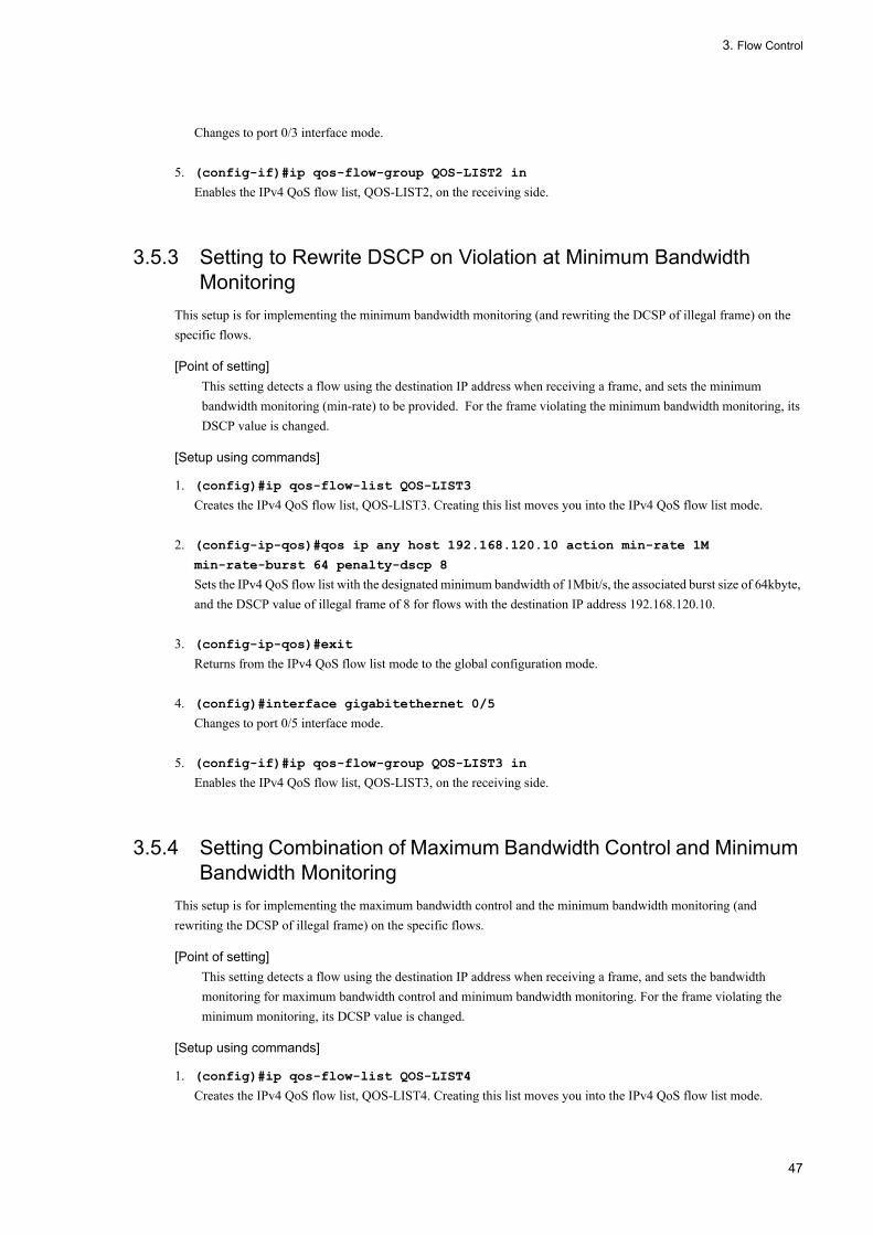
3. Flow Control
Changes to port 0/3 interface mode.
5. (config-if)#ip qos-flow-group QOS-LIST2 in
Enables the IPv4 QoS flow list, QOS-LIST2, on the receiving side.
3.5.3 Setting to Rewrite DSCP on Violation at Minimum Bandwidth Monitoring
This setup is for implementing the minimum bandwidth monitoring (and rewriting the DCSP of illegal frame) on the specific flows.
[Point of setting]This setting detects a flow using the destination IP address when receiving a frame, and sets the minimum bandwidth monitoring (min-rate) to be provided. For the frame violating the minimum bandwidth monitoring, its DSCP value is changed.
[Setup using commands]
1. (config)#ip qos-flow-list QOS-LIST3
Creates the IPv4 QoS flow list, QOS-LIST3. Creating this list moves you into the IPv4 QoS flow list mode.
2. (config-ip-qos)#qos ip any host 192.168.120.10 action min-rate 1M
min-rate-burst 64 penalty-dscp 8
Sets the IPv4 QoS flow list with the designated minimum bandwidth of 1Mbit/s, the associated burst size of 64kbyte, and the DSCP value of illegal frame of 8 for flows with the destination IP address 192.168.120.10.
3. (config-ip-qos)#exit
Returns from the IPv4 QoS flow list mode to the global configuration mode.
4. (config)#interface gigabitethernet 0/5
Changes to port 0/5 interface mode.
5. (config-if)#ip qos-flow-group QOS-LIST3 in
Enables the IPv4 QoS flow list, QOS-LIST3, on the receiving side.
3.5.4 Setting Combination of Maximum Bandwidth Control and Minimum Bandwidth Monitoring
This setup is for implementing the maximum bandwidth control and the minimum bandwidth monitoring (and rewriting the DCSP of illegal frame) on the specific flows.
[Point of setting]This setting detects a flow using the destination IP address when receiving a frame, and sets the bandwidth monitoring for maximum bandwidth control and minimum bandwidth monitoring. For the frame violating the minimum monitoring, its DCSP value is changed.
[Setup using commands]
1. (config)#ip qos-flow-list QOS-LIST4
Creates the IPv4 QoS flow list, QOS-LIST4. Creating this list moves you into the IPv4 QoS flow list mode.
47

3. Flow Control
2. (config-ip-qos)#qos ip any host 192.168.130.10 action max-rate 5M
max-rate-burst 512 min-rate 1M min-rate-burst 64 penalty-dscp 8
For flows with the destination IP address 192.168.130.10, sets the IPv4 QoS flow list with the designated bandwidth for the maximum bandwidth control of 5Mbit/s and the associated burst size of 512kbyte, the designated minimum bandwidth of 1Mbit/s and the associated burst size of 64kbyte/s, and the DSCP value of illegal frame of 8.
3. (config-ip-qos)# exit
Returns from the IPv4 QoS flow list mode to the global configuration mode.
4. (config)#interface gigabitethernet 0/7
Changes to port 0/7 interface mode.
5. (config-if)#ip qos-flow-group QOS-LIST4 in
Enables the IPv4 QoS flow list, QOS-LIST4, on the receiving side.
48

3. Flow Control
3.6 Operation of Bandwidth Monitoring
Use the "show qos-flow" command to confirm that the configuration is applied to the operation.
3.6.1 Checking Maximum Bandwidth ControlThe following image shows checking for the operations of the Maximum Bandwidth Control:
Figure 3-5: Checking Maximum Bandwidth Control
> show qos-flow 0/1 Date 2005/12/01 13:00:00 UTCUsing Port:0/1 inIP qos-flow-list:QOS-LIST1 ip any host 192.168.100.10 action max-rate 5M max-rate-burst 512 matched packets(max-rate over) : 7 matched packets(max-rate under): 28>
Make sure that the QOS-LIST1 listing information shows responses, "designated bandwidth of maximum bandwidth control (max-rate 5M)" and "burst size of maximum bandwidth control (max-rate-burst 512)".
3.6.2 Checking Queueing Priorities on Violation for Minimum Bandwidth Monitoring
The following image shows checking for the queueing priority on violation at the minimum bandwidth monitoring:
Figure 3-6: Checking Queueing Priorities on Violation for Minimum Bandwidth Monitoring
> show qos-flow 0/3 Date 2005/12/01 13:00:00 UTCUsing Port:0/3 inIP qos-flow-list:QOS-LIST2 ip any host 192.168.110.10 action min-rate 1M min-rate-burst 64 penalty-discard-class 1 matched packets(min-rate over) : 9826 matched packets(min-rate under): 74699826>
Make sure that the QOS-LIST2 listing information shows responses, "designated minimum bandwidth (min-rate 1M)" and "burst size of designated minimum bandwidth (min-rate-burst 64)" and "queueing priority of illegal frame (penalty-discard-class 1)".
3.6.3 Checking Rewriting of DSCP on Violation for Designated Minimum Bandwidth
The following image shows checking for the rewriting of DSCP on violation for the designated minimum bandwidth:
Figure 3-7: Checking Rewriting of DSCP on Violation for Designated Minimum Bandwidth
> show qos-flow 0/5 Date 2005/12/01 13:00:00 UTCUsing Port:0/5 inIP qos-flow-list:QOS-LIST3 ip any host 192.168.110.10 action min-rate 1M min-rate-burst 64 penalty-dscp
49
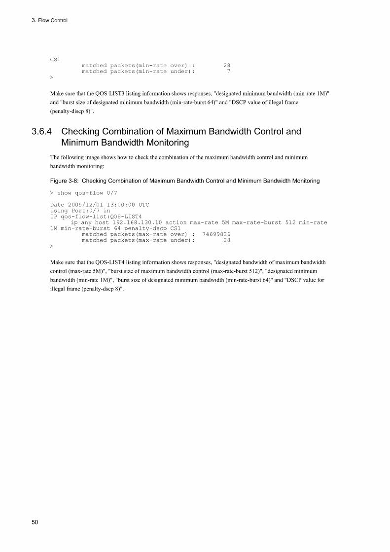
3. Flow Control
CS1 matched packets(min-rate over) : 28 matched packets(min-rate under): 7>
Make sure that the QOS-LIST3 listing information shows responses, "designated minimum bandwidth (min-rate 1M)" and "burst size of designated minimum bandwidth (min-rate-burst 64)" and "DSCP value of illegal frame (penalty-discp 8)".
3.6.4 Checking Combination of Maximum Bandwidth Control and Minimum Bandwidth Monitoring
The following image shows how to check the combination of the maximum bandwidth control and minimum bandwidth monitoring:
Figure 3-8: Checking Combination of Maximum Bandwidth Control and Minimum Bandwidth Monitoring
> show qos-flow 0/7 Date 2005/12/01 13:00:00 UTCUsing Port:0/7 inIP qos-flow-list:QOS-LIST4 ip any host 192.168.130.10 action max-rate 5M max-rate-burst 512 min-rate 1M min-rate-burst 64 penalty-dscp CS1 matched packets(max-rate over) : 74699826 matched packets(max-rate under): 28>
Make sure that the QOS-LIST4 listing information shows responses, "designated bandwidth of maximum bandwidth control (max-rate 5M)", "burst size of maximum bandwidth control (max-rate-burst 512)", "designated minimum bandwidth (min-rate 1M)", "burst size of designated minimum bandwidth (min-rate-burst 64)" and "DSCP value for illegal frame (penalty-dscp 8)".
50

3. Flow Control
3.7 Marker Overview
The marker overwrites the user priority in the VLAN tag and DSCP in the IP header of frames detected in the Flow Detection. The figure below indicates the positioning of the marker explained in this section.
Figure 3-9: Positioning of Marker
3.7.1 Rewriting User PriorityThis function updates the user priority in the VLAN tag of frames detected in the Flow Detection. In the following figure, the upper 3 bits of the tag information field correspond to the user priority:
Figure 3-10: Header Format of VLAN Tag
The following figure shows the target VLAN tunnel frame format when rewriting the user priority of the frames using the VLAN tunneling:
Figure 3-11: Schematic of VLAN Tunnel Frame Format
For the following frames, you cannot rewrite the user priority.
51

3. Flow Control
• Frame transmitted in port where VLAN tunneling was set.
The process of rewriting the user priority for the frames received at the port where VLAN tunneling has been set cannot be set simultaneously with the function of taking over user priority.
If you perform neither the process of rewriting user priority nor the process of relaying user priority, the user priority in the following table applies.
Table 3-9: User Priority at the Time of Frame Reception
When the priority assignment function is also set, the user priority is fixed to the appropriate value according to the CoS value determined by the priority assignment function.
The following table lists the user priorities where the priority assignment function and the user priority rewriting function are set together:
Table 3-10: User Priorities According to the Combination of Priority Assignment and User Priority Rewriting Functions
3.7.2 Taking Over User PriorityWhen the VLAN tunneling function is used to add a VLAN tag to frames from the access line and relay them to the backbone line, this function is used to take over the user priority for the frame detected in flow detection to the CoS value for the backbone line's user priority (user priority of an additional VLAN tag) and the priority determination function.
The process of taking over user priority can be set at the Ethernet interface having VLAN tunneling specified.
The following table shows the operation taking place when the process of taking over user priority has been set.
User priority at the time of frame reception
Target frames
3 • Frame that is received with no VLAN tag and sent together with a VLAN tag• Frame that is relayed from an access line to a backbone line by means of the VLAN
tunneling function• Frame that is received at the port where tag conversation has been set and the tag of which
has been converted
User Priority of recevedflame
• Frame having a VLAN tag that is relayed from one access line to another by means of theVLAN tunneling function
• Frame received together with a VLAN tag and sent together with a VLAN tag at a port wheretag conversion is not set and VLAN tunneling is not set
CoS Value Determined by Priority Assignment Function User Priority
0 0
1 1
2 2
3 3
4 4
5 5
6 6
7 7
52

3. Flow Control
Table 3-11: Operation Taking Place When the Function of Taking Over User Priority Has Been Set
The process of taking over user priority can be set simultaneously with neither the function of rewriting user priority nor the priority determination function (to specify the CoS value).
For the CoS value applicable when the process of taking over user priory, see "3.10.2 CoS Value and Queueing
Priority" and for details about user priority, see "3.7.1 Rewriting User Priority"
3.7.3 Rewriting DSCPThis function rewrites the DSCP value, which consists of the upper 6 bits of the TOS field (for an IPv4 header) or the traffic class field (for an IPv6 header). The following figure shows the formats of TOS field and traffic class field:
Figure 3-12: TOS Field Format
User priority of a frame detected during flow detection
Frame transmitted
User priority CoS value
No VLAN tag 0 0
0 0 0
1 1 1
2 2 2
3 3 3
4 4 4
5 5 5
6 6 6
7 7 7
53

3. Flow Control
Figure 3-13: Traffic Class Field Format
This function rewrites the upper 6 bits of the TOS field or traffic class field of a detected flow.
The DSCP of the flow exceeding the designated minimum bandwidth can be rewritten by the instruction from the bandwidth monitoring. For example, the DSCP value of such a flow can be set to 0.
When the minimum bandwidth monitoring is also set, the action for illegal frames which specified for illegal frames
overrides the action specified by the DSCP rewriting function.
54

3. Flow Control
3.8 Configuration of Marker
3.8.1 Setting to Rewrite User PriorityThis setup is required to rewrite the user priority for a specific flow.
[Point of setting]This setting detects a flow using the destination IP address when receiving a frame, and rewrites the user priority.
[Setup using commands]
1. (config)#ip qos-flow-list QOS-LIST1
Creates an IPv4 QoS flow list (QOS-LIST1). Creating this list moves you into the IPv4 QoS flow list mode.
2. (config-ip-qos)#qos ip any host 192.168.100.10 action replace-user-priority 6
Sets the IPv4 QoS flow list with the destination IP address 192.168.100.10 to rewrite the user priority to 6.
3. (config-ip-qos)# exit
Returns from the IPv4 QoS flow list mode to the global configuration mode.
4. (config)#interface gigabitethernet 0/1
Changes to port 0/1 interface mode.
5. (config-if)#ip qos-flow-group QOS-LIST1 in
Enables the IPv4 QoS flow list, QOS-LIST1, on the receiving side.
3.8.2 Setting the Process of Taking Over User PriorityThis should be set when user priority is taken over for a specific flow.
[Point of setting]Upon frame reception, flow detection is conducted according to the destination IP address to take over user priority.
[Setup using commands]
1. (config)#ip qos-flow-list QOS-LIST2
Creates the IPv4 QoS flow list, QOS-LIST2. Creating this list moves you into the IPv4 QoS flow list mode.
2. (config-ip-qos)#qos ip any host 192.168.100.10 action copy-user-priority
192.168.100.10 ------ The IP address of 192.168.100.10 is used as the destination and the IPv4 QoS flow list for taking over user priority is set.
3. (config-ip-qos)#exit
Returns from the IPv4 QoS flow list mode to the global configuration mode.
4. (config)#interface gigabitethernet 0/1
Changes to port 0/1 interface mode.
5. (config-if)#ip qos-flow-group QOS-LIST2 in
Enables the IPv4 QoS flow list, QOS-LIST2, on the receiving side.
55

3. Flow Control
3.8.3 Setting to Rewrite DSCPThis setup is required to rewrite DSCP for a specific flow.
[Point of setting]This setting detects a flow using the destination IP address when receiving a frame, and rewrites the DSCP value.
[Setup using commands]
1. (config)#ip qos-flow-list QOS-LIST2
Creates the IPv4 QoS flow list, QOS-LIST2. Creating this list moves you into the IPv4 QoS flow list mode.
2. (config-ip-qos)#qos ip any host 192.168.100.10 action replace-dscp 63
Sets the IPv4 QoS flow list with the destination IP address 192.168.100.10 to rewrite the DSCP value to 63.
3. (config-ip-qos)# exit
Returns from the IPv4 QoS flow list mode to the global configuration mode.
4. (config)#interface gigabitethernet 0/3
Changes to port 0/3 interface mode.
5. (config-if)#ip qos-flow-group QOS-LIST2 in
Enables the IPv4 QoS flow list, QOS-LIST2, on the receiving side.
56

3. Flow Control
3.9 Operation of Marker
Use the "show qos-flow" command to confirm that the configuration is applied to the operation.
3.9.1 Checking User Priority Rewriting FunctionThe following image shows how to check the rewritten user priority:
Figure 3-14: Checking User Priority Rewriting Function
> show qos-flow 0/1 Date 2005/12/01 13:00:00 UTCUsing Port:0/1 inIP qos-flow-list:QOS-LIST1 ip any host 192.168.100.10 action replace-user-priority 6 matched packets : 0>
Make sure that the QOS-LIST1 list information shows a response, "replace-user-priority 6".
3.9.2 Checking the Process of Taking Over User PriorityThe following figure shows how to check the process of taking over user priority.
Figure 3-15: Checking the Process of Taking Over User Priority
> show qos-flow 0/1Date 2007/03/01 13:00:00 UTCUsing Port:0/1 inIP qos-flow-list:QOS-LIST2 ip any host 192.168.100.10 action copy-user-priority matched packets : 0>
Check that "copy-user-priority" is displayed in the QOS-LIST2 list information.
3.9.3 Checking DSCP Rewriting FunctionThe following image shows how to check the rewritten DSCP:
Figure 3-16: Checking DSCP Rewriting Function
> show qos-flow 0/3 Date 2005/12/01 13:00:00 UTCUsing Port:0/3 inIP qos-flow-list:QOS-LIST2 ip any host 192.168.100.10 action replace-dscp 63 matched packets : 0>
Make sure that the QOS-LIST2 list information shows a response, "replace-dscp 63".
57

3. Flow Control
3.10 Priority Assignment Overview
The priority assignment is the function to specify the priority of a frame detected through the flow detection as the CoS value which is used to determine the transmission queue.
The figure below indicates the positioning of the priority assignment explained in this section.
Figure 3-17: Positioning of Priority Assignment
3.10.1 Changing which frames are subject to priority determinationThis functionality changes which frames are subject to priority determination. The following table shows the actions related to the setting for changing which frames are subject to priority determination.
Table 3-12: Actions when using the functionality for changing which frames are subject to priority determination
Legend: Y: Becomes subject to priority determination, N: Does not become subject to priority determination
3.10.2 CoS Value and Queueing PriorityThe CoS value indicates the priority of a frame in the LANSW module. The queuing priority indicates the likelihood of a frame to be discarded in each queue.
The following table lists the allowable ranges for the CoS values and queueing priorities.
Table 3-13: Allowable Ranges of CoS Values and Queueing Priorities
Setting for changing which frames are subject to priority determination
Frame type
Frames sent to the Switch Frames forwarded by the Switch
Not set Y Y
Set N Y
Item Allowable Range
CoS value 0 to 7
Queuing priority 1 to 3
58

3. Flow Control
The process of specifying the CoS value cannot be set simultaneously with the process of taking over user priority.
If the priority assignment is not set up for the flow control, the default CoS value and queueing priority shown in the table below is used.
Table 3-14: Default CoS Value and Queueing Priority
For the following frames, the CoS value and queueing priority are fixed regardless of the priority setting of the flow control.
The table below shows the frames which cannot be changed by the priority assignment:
Table 3-15: List of Frames Not Subjected to Priority Assignment
3.10.3 CoS MappingThe CoS mapping determines the transmission queue according to the CoS value determined by the user priority mapping or that specified through the priority assignment for the flow control.
The following table lists the mappings between the CoS values and transmission queues:
Item dafault Allowable Range
CoS value The user priority mapping is followed
• Frame not detected during flow detection• Frame detected during flow detection and conducting neither
priority determination (to specify the CoS value) nor marking (to take over priority)
Queuing priority 3 • Frame not detected during flow detection• Frame detected during flow detection and not conducting priority
determination (to specify the queuing priority value)
Frame Type CoS Value Queuing Priority
Frames sent by the LANSW module autonomously 7 3
Frames received by the LANSW module• ARP frames• Frames used for line test
5 3
Frames received by the LANSW module• Frames recognized as those subject to displacement detection MAC
address learning
2 3
Packets/frames relayed through layer 3 and received by the LANSW module• IPv4 and IPv6 packets larger than MTU• Frames with TTL of 1• Frames with hop-limit of 1• Frames with IP options• Frames with IPv6 extension header
2 3
Packets relayed through layer 3 and received by the LANSW module• IPv4 and IPv6 packets with unknown destination
2 3
Frames relayed by the LANSW module through layer 3• Frames fragmented by the LANSW module• Frames with IP options• Frames with IPv6 extension header• Relayed frames accumulated in the LANSW module temporarily due to
ARP/NDP unresolved
7 3
59

3. Flow Control
Table 3-16: Mapping between CoS Values and Transmission Queues
3.10.4 Notes on Using Priority Assignment
(1) Priority assignment for frames to the LANSW module
On the LANSW module, not only the relayed frames but also frames terminating at the LANSW module are subject to the QoS flow detection. Therefore, specifying the operation to increase the priority of frames terminating at the LANSW module may prevent the LANSW module from receiving protocol control frames.
In this case, lower the priority of frames terminating at the LANSW module.
CoS Value Queue Number When Sending
Transmission Queue Length 64 Transmission Queue Length 1976
0 1 1
1 2 1
2 3 1
3 4 1
4 5 1
5 6 1
6 7 1
7 8 2
60

3. Flow Control
3.11 Configuration of Priority Assignment
3.11.1 Setting CoS ValueThis setup is required to set the CoS value on a specific flow.
[Point of setting]Set the flow detection by destination IP address to be executed to set CoS value when receiving frames.
[Setup using commands]
1. (config)#ip qos-flow-list QOS-LIST1
Creates an IPv4 QoS flow list (QOS-LIST1). Creating this list moves you into the IPv4 QoS flow list mode.
2. (config-ip-qos)# qos ip any host 192.168.100.10 action cos 6
Sets the IPv4 QoS flow list with the destination address 192.168.100.10 and the CoS value of 6.
3. (config-ip-qos)# exit
Returns from the IPv4 QoS flow list mode to the global configuration mode.
4. (config)#interface gigabitethernet 0/1
Changes to port 0/1 interface mode.
5. (config-if)#ip qos-flow-group QOS-LIST1 in
Enables the IPv4 QoS flow list, QOS-LIST1.
61

3. Flow Control
3.12 Operation of Priority
3.12.1 Checking PriorityExecute the "show qos queueing" command with the line supplied with traffic (frames with destination IP address 192.168.100.10) to identify the queue number being queued. The target Ethernet interface can be identified with NIF number 0 and Line number 2.
Figure 3-18: Checking Priority
> show qos queueing 0/2 Date 2005/12/01 13:00:00 UTCNIF0/Line2 (outbound) Max_Queue=8, Rate_limit=100Mbit/s, QmoBurst_size=32kbyte,e=pq/tail_drop Queue1: Qlen= 0, Limit_Qlen= 64 Queue2: Qlen= 0, Limit_Qlen= 64 Queue3: Qlen= 0, Limit_Qlen= 64 Queue4: Qlen= 0, Limit_Qlen= 64 Queue5: Qlen= 0, Limit_Qlen= 64 Queue6: Qlen= 1, Limit_Qlen= 64 ...1 Queue7: Qlen= 0, Limit_Qlen= 64 Queue8: Qlen= 0, Limit_Qlen= 64 discard packets HOL1= 0, HOL2= 0, Tail_drop= 0
1. Make sure that Qlen value has been incremented only for Queue6.
62
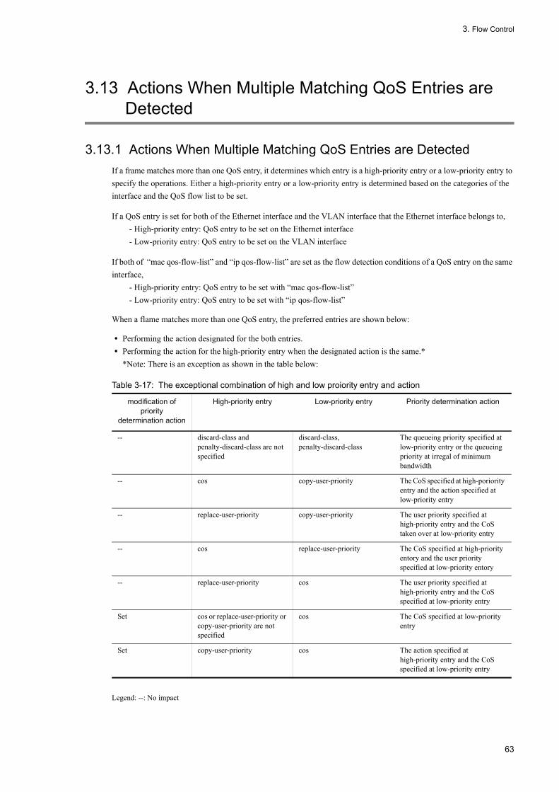
3. Flow Control
3.13 Actions When Multiple Matching QoS Entries are Detected
3.13.1 Actions When Multiple Matching QoS Entries are DetectedIf a frame matches more than one QoS entry, it determines which entry is a high-priority entry or a low-priority entry to specify the operations. Either a high-priority entry or a low-priority entry is determined based on the categories of the interface and the QoS flow list to be set.
If a QoS entry is set for both of the Ethernet interface and the VLAN interface that the Ethernet interface belongs to,- High-priority entry: QoS entry to be set on the Ethernet interface- Low-priority entry: QoS entry to be set on the VLAN interface
If both of “mac qos-flow-list” and “ip qos-flow-list” are set as the flow detection conditions of a QoS entry on the same interface,
- High-priority entry: QoS entry to be set with “mac qos-flow-list”- Low-priority entry: QoS entry to be set with “ip qos-flow-list”
When a flame matches more than one QoS entry, the preferred entries are shown below:
• Performing the action designated for the both entries.• Performing the action for the high-priority entry when the designated action is the same.*
*Note: There is an exception as shown in the table below:
Table 3-17: The exceptional combination of high and low proiority entry and action
Legend: --: No impact
modification of priority
determination action
High-priority entry Low-priority entry Priority determination action
-- discard-class and penalty-discard-class are not specified
discard-class, penalty-discard-class
The queueing priority specified at low-priority entry or the queueing priority at irregal of minimum bandwidth
-- cos copy-user-priority The CoS specified at high-poriority entry and the action specified at low-priority entry
-- replace-user-priority copy-user-priority The user priority specified at high-priority entry and the CoS taken over at low-priority entry
-- cos replace-user-priority The CoS specified at high-priority entory and the user priority specified at low-priority entory
-- replace-user-priority cos The user priority specified at high-priority entry and the CoS specified at low-priority entry
Set cos or replace-user-priority or copy-user-priority are not specified
cos The CoS specified at low-priority entry
Set copy-user-priority cos The action specified at high-priority entry and the CoS specified at low-priority entry
63

3. Flow Control
64

4 Transmission ControlThis chapter explains the transmission control (shaper and discard control) of the LANSW module.
4.1 Shaper Overview
4.2 Configuration of Shaper
4.3 Operation of Shaper
4.4 Discard Control Overview
4.5 Configuration of Discard Control
4.6 Operation of Discard Control
65

4. Transmission Control
4.1 Shaper Overview
4.1.1 Outline of Legacy ShaperThe shaper is the function to control the order and bandwidth of outgoing frames. The following figure illustrates the positioning of the shaper described in this section.
Figure 4-1: Positioning of Shaper
As shown in the following figure, the legacy shaper consists of the scheduling, which determines the queue whose frames are sent next, and the port bandwidth control, which shapes the Ethernet interface bandwidth. The following figure shows the concept of the legacy shaper:
Figure 4-2: Concept of Legacy Shaper
4.1.2 Setting Transmission Queue LengthThe LANSW module allows the transmission queue length to be changed according to the network configuration and application. To change the transmission queue length, use the configuration command "limit-queue-length". Increasing the queue length can reduce the queue overflow due to burst traffic. The specified queue length applies to all Ethernet
66

4. Transmission Control
interfaces of the LANSW module.
When the queue length is not specified, it is set to 64. To specify the queue length of 1976, use the configuration command "flow control" to set for "using pause packet".
Table 4-1: Transmission Queue Length and Corresponding Application
*When the transmission queue length is 1976, the queue length is assigned only to queue 1 and queue 2, resulting in the following scheduling operation. PQ, RR, WRR: Queue 1 and queue 2 operate with PQ, RR, and WRR.2PQ+6DRR: Queue 1 and queue 2 operate with DRR. 2PQ+6WRR: Queue 1 and queue 2 operate with WRR.
4.1.3 SchedulingThe scheduling is a function to control the order to send queued frames. The LANSW module has six types of scheduling function. The following table describes the scheduling operation of each type.
Table 4-2: Operational Description of Scheduling
Transmission Queue Length
Objective Application
64 Used to enable the transmission control when the load is equally distributed to all queues.
1976* Suitable to reduce the queue overflow due to burst traffic.
Scheduling Type
Conceptual Diagram Description of Operation Application Example
PQ Priority queuing. When more than one queue has queued frames, the LANSW module sends frames in the order of queue priority, starting with queue 8 (Q#8 in the left figure).
Where the traffic priority should be fully observed.
RR Round robin. When more than one queue has frames, the LANSW module sequentially checks queues to send one frame from one queue at a time. It controls the number of frames in each queue to be equal, regardless of the frame length.
Where only data type traffic is handled.
WRR Weighted (the number of frames) round robin. When more than one queue has frames, the LANSW module sequentially checks queues to send frames according to the weight (the number of frames) of "z:y:x:w:v:u:t:s" specified for queue 8 to 1 (Q#8 to Q#1 in the left figure).
Where sending the all traffics are required and higher- and lower-priority traffics coexist
67
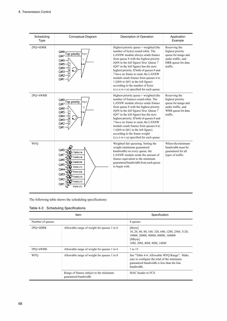
4. Transmission Control
The following table shows the scheduling specifications:
Table 4-3: Scheduling Specifications
2PQ+6DRR Highest priority queue + weighted (the number of bytes) round robin. The LANSW module always sends frames from queue 8 with the highest priority (Q#8 in the left figure) first. Queue 7 (Q#7 in the left figure) has the next highest priority. If both of queues 8 and 7 have no frame to send, the LANSW module sends frames from queues 6 to 1 (Q#6 to Q#1 in the left figure) according to the number of bytes (z:y:x:w:v:u) specified for each queue.
Reserving the highest priority queue for image and audio traffic, and DRR queue for data traffic.
2PQ+6WRR Highest priority queue + weighted (the number of frames) round robin. The LANSW module always sends frames from queue 8 with the highest priority (Q#8 in the left figure) first. Queue 7 (Q#7 in the left figure) has the next highest priority. If both of queues 8 and 7 have no frame to send, the LANSW module sends frames from queues 6 to 1 (Q#6 to Q#1 in the left figure) according to the frame weight (z:y:x:w:v:u) specified for each queue.
Reserving the highest priority queue for image and audio traffic, and WRR queue for data traffic.
WFQ Weighted fair queueing. Setting the weight (minimum guaranteed bandwidth) on every queue, the LANSW module sends the amount of frames equivalent to the minimum guaranteed bandwidth from each queue to begin with.
Where the minimum bandwidth must be guaranteed for all types of traffic.
Item Specification
Number of queues 8 queues
2PQ+6DRR Allowable range of weight for queues 1 to 6 [kbyte]10, 20, 40, 80, 160, 320, 640, 1280, 2560, 5120, 10000, 20000, 40000, 80000, 160000[Mbyte]10M, 20M, 40M, 80M, 160M
2PQ+6WRR Allowable range of weight for queues 1 to 6 1 to 15
WFQ Allowable range of weight for queues 1 to 8 See "Table 4-4: Allowable WFQ Range". Make sure to configure the total of the minimum guaranteed bandwidth is less than the line bandwidth.
Range of frames subject to the minimum guaranteed bandwidth
MAC header to FCS
Scheduling Type
Conceptual Diagram Description of Operation Application Example
68

4. Transmission Control
Table 4-4: Allowable WFQ Range
(Legend) -: Not applicable*1 1G and 1M correspond to 1000000k and 1000k, respectively.*2 For the setting value more than 1000k, set the value in increment of 100k (i.e., 1000, 1100, 1200, ---, 10000000).*3 For the setting value less than 1000k, set the value in increment of 64k (i.e., 64, 128, 192, ---, 960).
4.1.4 Port Bandwidth ControlThe port bandwidth control is the function to shape the transmission bandwidth of the entire line into the specified bandwidth, after scheduling. This control allows the connection to the wide area Ethernet service.
For example, if the line bandwidth is 1Gbit/s and the bandwidth subscribed with ISP is 500Mbit/s, the port bandwidth control enables the LANSW module to limit the bandwidth to 400Mbit/s or less for sending frames. This helps to avoid congestion caused by the difference between the Ethernet interface bandwidth and the subscribing bandwidth.
Port band control is based on the Leaky Bucket algorithm using a holed bucket as its model. The model of the Leaky Bucket algorithm is shown below.
Figure 4-3: Model of the Leaky Bucket Algorithm
Water equivalent to the received frame size is poured into the bucket and water equivalent to the transmitted band for port band control flows as a transmitted frame. The depth of a bucket (that is, the quantity of water permitted when a huge amount of water is poured at a time) corresponds to the burst size. If traffic is transmitted when the bucket is empty, the fluctuation of the transmission band is proportional to the burst size. When the quantity of water accumulated reaches the burst size, frames are accumulated in the transmission queue.
The following table shows the setup range for port band control. The setup range must be a value not exceeding the line speed. The setting is not possible if the line status is half-duplex mode. If setting is impossible, the operating log is displayed and the setup for port band control becomes valid.
Set unit*1 Setting Range Increment
Gbit/s 1G to 10G 1Gnit/s
Mbit/s 1M to 10000M 1Mbit/s
kbit/s 1000 to 10000000 100kbit/s*2
64 to 960 64kbit/s*3
69

4. Transmission Control
Table 4-5: Setting range of Port band control
(Legend) -: Not applicable*1 1G and 1M correspond to 1000000k and 1000k, respectively.*2 For the setting value more than 1000k, set the value in increment of 100k (i.e., 1000, 1100, 1200, ---, 10000000).*3 For the setting value less than 1000k, set the value in increment of 64k (i.e., 64, 128, 192, ---, 960).
The burst size setting range is shown as follows.
Setting range of burst size
4, 8, 16, or 32 kbytes (The default value is 32 kbytes.)
The following table shows the characteristics of the burst size depending on the properties of the Leaky Bucket algorithm.
Table 4-6: Setting range of Port band conroll
The scope of port bandwidth control is from the MAC header to FCS of a frame. For details, see "Figure 4-4: Scope of Port Bandwidth Control".
Figure 4-4: Scope of Port Bandwidth Control
4.1.5 Notes on Using Shaper
(1) Notes on scheduling against exhaustion of available packet buffer space
If the LANSW module receives a large amount of traffic exceeding the bandwidth of output line, the available space of the packet buffer may be exhausted. Therefore, received frames are not queued but discarded. As a result, frames may not be sent according to the specified scheduling.
To check the exhaustion of the available packet buffer space, confirm that the HOL1 or HOL2 counter of the "show qos queuing" command has been incremented.
If exhaustion of the available packet buffer space occurs constantly, the network design must be reviewed.
Set unit*1 Setting Range Increment
Gbit/s 1G to 10G 1Gnit/s
Mbit/s 1M to 10000M 1Mbit/s
kbit/s 1000 to 10000000 100kbit/s*2
64 to 960 64kbit/s*3
Burst size Feature
Decreasing Relatively burst traffic is likely to be discarded. If traffic is transmitted when communication is not in process, the fluctuation of the transmission band is relatively small.
Increasing Relatively burst traffic is likely to be discarded. If traffic is transmitted when communication is not in process, the fluctuation of the transmission band is relatively big.
70

4. Transmission Control
4.2 Configuration of Shaper
4.2.1 Setting Scheduling[Point of setting]
You should create information about the QoS queue list containing the scheduling and set it in the corresponding port.
[Setup using commands]
1. (config)#qos-queue-list QUEUE-PQ pq
Set the scheduling (PQ) in the QoS queue list information (QLIST-PQ).
2. (config)#interface gigabitethernet 0/1
Changes to port 0/1 interface mode.
3. (config-if)#qos-queue-group QUEUE-PQ
The QoS queue list name is specified for QoS queue interface information, and QoS queue list information is made effective.
4.2.2 Setting Port Bandwidth ControlThe setting is required if the output band for the corresponding port is made to be lower than the band for a real circuit.
[Point of setting]Setting (20Mbit/s) of the band by the port band control and the burst size are set to corresponding port (100Mbit/s) (4kbyte).
[Setup using commands]
1. (config)# interface gigabitethernet 0/2It shifts to the interface mode of port 0/2.
2. (config-if)# speed 100
(config-if)# duplex full
The speed of the line of the corresponding port is set to 100Mbit/s.
3. (config-if)# speed 100
(config-if)# duplex full
The port band is set in 20Mbit/s and the burst size is set to 4kbyte.
71

4. Transmission Control
4.3 Operation of Shaper
Use the "show qos queueing" command to check the legacy shaper settings defined on the Ethernet interface.
4.3.1 Checking SchedulingThe following image shows checking for Scheduling:
Figure 4-5: Checking Scheduling
> show qos queueing 0/1 Date 2007/03/01 13:00:00 UTCNIF0/Line1 (outbound) Max_Queue=8, Rate_limit=100Mbit/s, Burst_size=32kbyte, Qmode=pq/tail_drop ...1 Queue1: Qlen= 0, Limit_Qlen= 64 Queue2: Qlen= 0, Limit_Qlen= 64 Queue3: Qlen= 0, Limit_Qlen= 64 Queue4: Qlen= 0, Limit_Qlen= 64 Queue5: Qlen= 0, Limit_Qlen= 64 Queue6: Qlen= 0, Limit_Qlen= 64 Queue7: Qlen= 0, Limit_Qlen= 64 Queue8: Qlen= 0, Limit_Qlen= 64 discard packets HOL1= 0, HOL2= 0, Tail_drop= 0
1. Make sure that the content of the "Qmode" parameter meets the preset scheduling (pq/tail_drop in this example).
4.3.2 Checking Port band controlFigure 4-6: Checking RR
> show qos queueing 0/13Date 2007/03/01 13:00:00 UTCNIF0/Port13 (outbound) Max_Queue=8, Rate_limit=20Mbit/s, Burst_size=4kbyte, Qmode=pq/tail_drop ... 1,2 Queue1: Qlen= 0, Limit_Qlen= 64 Queue2: Qlen= 0, Limit_Qlen= 64 Queue3: Qlen= 0, Limit_Qlen= 64 Queue4: Qlen= 0, Limit_Qlen= 64 Queue5: Qlen= 0, Limit_Qlen= 64 Queue6: Qlen= 0, Limit_Qlen= 64 Queue7: Qlen= 0, Limit_Qlen= 64 Queue8: Qlen= 0, Limit_Qlen= 64 discard packets HOL1= 0, HOL2= 0, Tail_drop= 0
1. Make sure that the content of the "Rate_limit" parameter meets the specified band setup (20Mbit/s in this example).
2. Make sure that the content of the "Burst_size" parameter meets the specified burst size (4kbyte in this example).
72

4. Transmission Control
4.4 Discard Control Overview
The figure below indicates the positioning of the discard control explained in this section.
Figure 4-7: Positioning of Discard Control
4.4.1 Discard ControlThe discard control is a function to determine whether to put a frame into a queue or discard it depending on the queuing priority indicating the likelihood of frames to be discarded, and the amount of queued frames.
If a queue has frames, changing its queuing priority enables the finer QoS control.
The maximum number of queued frames in a queue is referred to as "Queue Length".
The LANSW module implements the discard control by means of tail drop method.
(1) Tail drop
This function discards frames if a queue length exceeds the discard threshold. The discard threshold depends on the assigned queuing priority. The higher the queuing priority is, the less possibility frames are discarded. The concept of tail drop is shown in the figure below. When the discard threshold of queuing priority 2 is exceeded, the frames with queuing priority 2 are all discarded.
Figure 4-8: Concept of Tail Drop
73

4. Transmission Control
The following table lists the discard thresholds associated with the queueing priorities. The discard threshold represents the ratio of queued frames to the queue length in percentage.
Table 4-7: Discard Threshold of Tail Drop
Queuing Priority Discard Threshold [%]
1 50
2 75
3 100
74

4. Transmission Control
4.5 Configuration of Discard Control
4.5.1 Setting Queuing PriorityThis setup is for setting the queuing priority for a specific flow.
[Point of setting]This setting detects a flow using the destination IP address when receiving a frame, and sets the queuing priority.
[Setup using commands]
1. (config)#ip qos-flow-list QOS-LIST2
Creates the IPv4 QoS flow list, QOS-LIST2. Creating this list moves you into the IPv4 QoS flow list mode.
2. (config-ip-qos)#qos ip any host 192.168.100.10 action discard-class 1
Sets the QoS flow list with the destination IP address 192.168.100.10 and the queueing priority of 1.
3. (config-ip-qos)# exit
Returns from the IPv4 QoS flow list mode to the global configuration mode.
4. (config)#interface gigabitethernet 0/1
Changes to port 0/1 interface mode.
5. (config-if)#ip qos-flow-group QOS-LIST2 in
Enables the QoS flow list, QOS-LIST2, on the receiving side.
75

4. Transmission Control
4.6 Operation of Discard Control
Execute the "show qos queueing" command with the line supplied with traffic (that can cause Qlen of Queue6 to be about 24) to identify the queue number with queued frames and the number of discarded packets. The target Ethernet interface can be identified with NIF number 0 and Line number 2.
4.6.1 Checking Queuing PriorityThe following image shows checking for the queuing priority:
Figure 4-9: Checking Queuing Priority
> show qos queueing 0/2 Date 2005/12/01 13:00:00 UTCNIF0/Line2 (outbound) Max_Queue=8, Rate_limit=100Mbit/s, Qmode=pq/tail_drop Queue1: Qlen= 0, Limit_Qlen= 64 Queue2: Qlen= 0, Limit_Qlen= 64 Queue3: Qlen= 0, Limit_Qlen= 64 Queue4: Qlen= 0, Limit_Qlen= 64 Queue5: Qlen= 0, Limit_Qlen= 64 Queue6: Qlen= 48, Limit_Qlen= 64 ..1,2 Queue7: Qlen= 0, Limit_Qlen= 64 Queue8: Qlen= 0, Limit_Qlen= 64 discard packets HOL1= 1514, HOL2= 0, Tail_drop= 18 ..2
1. Make sure that Qlen value has been incremented only for Queue6.
2. Make sure that Qlen is set to 24 and the counter for"discard packets" has been incremented.
76
Part 3 Layer 2 Authentication
5 Layer 2 AuthenticationThis chapter provides an overview of Layer 2 Authentication function on this device.
5.1 Overview
5.2 Coexistence of Layer 2 Authentication and Other Functions
5.3 Common Functions for Layer 2 Authentication
5.4 Notes on Using Layer 2 Authentication
5.5 Common Configurations of Layer 2 Authentication
77

5. Layer 2 Authentication
5.1 Overview
5.1.1 Layer 2 Authentication TypeThis device supports the following Layer 2 authentication functions:
• IEEE802.1X
This function provides the user authentication that complies with IEEE802.1X. It enables to authenticate the terminals that transmit the EAPOL packets required for IEEE802.1X authentication.
• Web authentication
Web authentication provides the user authentication using a general-purpose Web browser. It enables the authentication operations on the terminals that can use a general-purpose Web browser.
• MAC authentication
MAC authentication provides the authentication for terminals such as a printer that is unable to perform the authentication operations by users.
The Layer 2 authentication has the authentication modes according to the authentication operations. The table below shows the outline of functions for each authentication mode:
In addition, these functions contain the functions available or unavailable in combinations. For the combinations of the functions, see “5.2 Coexistence of Layer 2 Authentication and Other Functions”.
78
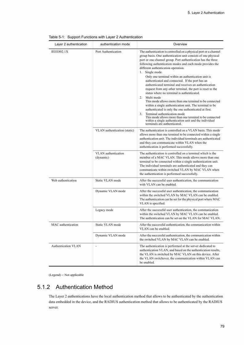
5. Layer 2 Authentication
Table 5-1: Support Functions with Layer 2 Authentication
(Legend) -: Not applicable
5.1.2 Authentication MethodThe Layer 2 authentications have the local authentication method that allows to be authenticated by the authentication data embedded in the device, and the RADIUS authentication method that allows to be authenticated by the RADIUS server.
Layer 2 authentication authentication mode Overview
IEEE802.1X Port Authentication The authentication is controlled on a physical port or a channel group basis. One authentication unit consists of one physical port or one channel group. Port authentication has the three following authentication modes and each mode provides the different authentication operation.1. Single mode
Only one terminal within an authentication unit is authenticated and connected. If the port has an authenticated terminal and receives an authentication request from any other terminal, the port is reset to the status where no terminal is authenticated.
2. Multi modeThis mode allows more than one terminal to be connected within a single authentication unit. The terminal to be authenticated is only the one authenticated at first.
3. Terminal authentication modeThis mode allows more than one terminal to be connected within a single authentication unit and the individual terminals are authenticated.
VLAN authentication (static) The authentication is controlled on a VLAN basis. This mode allows more than one terminal to be connected within a single authentication unit. The individual terminals are authenticated and they can communicate within VLAN when the authentication is performed successfully.
VLAN authentication (dynamic)
The authentication is controlled on a terminal which is the member of a MAC VLAN. This mode allows more than one terminal to be connected within a single authentication unit. The individual terminals are authenticated and they can communicate within switched VLAN by MAC VLAN when the authentication is performed successfully.
Web authentication Static VLAN mode After the successful user authentication, the communication with VLAN can be enabled.
Dynamic VLAN mode After the successful user authentication, the communication within the switched VLAN by MAC VLAN can be enabled. The authentication can be set for the physical port where MAC VLAN is specified.
Legacy mode After the successful user authentication, the communication within the switched VLAN by MAC VLAN can be enabled. The authentication can be set on the VLAN for MAC VLAN.
MAC authentication Static VLAN mode After the successful authentication, the communication within VLAN can be enabled.
Dynamic VLAN mode After the successful authentication, the communication within the switched VLAN by MAC VLAN can be enabled.
Authentication VLAN - The authentication is performed at the server dedicated to authentication VLAN, and based on the authentication results, the VLAN is switched by MAC VLAN on this device. After the VLAN switchover, the communication within VLAN can be enabled.
79

5. Layer 2 Authentication
Table 5-2: Authentication methods used in Layer 2 Authentication
Legend: Y: Supported; N: Not supported
5.1.3 Dynamic VLAN setting and Layer 2 Authentication on MAC VLANThe post-authentication VLAN can be set dynamically to accommodate the authenticated terminals at the ports to be authenticated on MAC VLAN in the Layer 2 authentication and the authentication modes as shown in the table below.
Meanwhile, when all the authentications for the terminals to be authenticated are disabled at the connected ports to be authenticated, the VLAN that has been set dynamically is removed.
Table 5-3: Layer 2 authentication function and authentication modes that permit dynamic VLAN assignment
At the MAC ports to be authenticated where the configuration command "switchport mac vlan" has been set, the VLAN switchover is disabled with the exception of the post-authentication VLAN that has been set by the configuration command. Additionally, when the configuration command "switchport mac vlan" are set in the status where VLAN has been set dynamically at the MAC ports to be authenticated, all the authentications are disabled on the authenticated terminals where the VLAN that has been set dynamically at the ports is specified as the post-authentication VLAN.
Layer 2 authentication authentication mode local authentication method
RADIUS authentication method
IEEE802.1X Port Authentication N Y
VLAN authentication (static) N Y
VLAN authentication (dynamic)
N Y
Web authentication Static VLAN mode Y Y
Dynamic VLAN mode Y Y
Legacy mode Y Y
MAC authentication Static VLAN mode Y Y
Dynamic VLAN mode Y Y
Layer 2 authentication function authentication mode
IEEE802.1X VLAN authentication (dynamic)
Web authentication Dynamic VLAN mode
MAC authentication Dynamic VLAN mode
80

5. Layer 2 Authentication
5.2 Coexistence of Layer 2 Authentication and Other Functions
This chapter explains the coexistence of the Layer 2 authentication and the other functions.
5.2.1 Coexistence of Layer 2 Authentication and Other FunctionsThe table below lists the coexistence specifications of the Layer 2 authentication and the other functions.
Table 5-4: Functional Compatibility with Other Functions
Layer 2 authentication
function
Function name Interoperability
IEEE 802.1X LinLink aggregation Should not be set simultaneously with channel group for LACP link aggregation.
VLAN Port VLAN Can be used for Port authentication and VLAN authentication (static).
Protocol VLAN Cannot be used simultaneously on this device.
MAC VLAN Can be used for VLAN authentication (dynamic).
Default VLAN Can be used for Port authentication and VLAN authentication (static).Can be used as the pre-authentication VLAN for VLAN authentication (dynamic).
VLAN extended function
VLAN tunneling Cannot be used simultaneously on this device.
EAPOL forwarding Cannot be used simultaneously on this device.
Spanning tree Port authentication and VLAN authentication (static) should not be set for the port with spanning tree.
Ring protocol Port authentication and VLAN authentication (static) should not be set for the ling port with Ring protocol.
IGMP snooping Cannot be used simultaneously with port authentication or VLAN authentication (static).
Authentication VLAN Cannot be used simultaneously on this device.
GSRP Cannot be used simultaneously on this device.
VRRP Authentications are enabled on a VLAN without VRRP settingand a port other than those with VLAN operating VRRP. In thefollowing cases, IEEE802.1X authentication is disabled:• For VLAN authentication (static), VLAN with VRRP
operating• For VLAN authentication (dynamic), authentication using
authentication default VLAN and MAC VLAN on VLAN with VRRP operating
• For port authentication, port where VLAN with VRRP operating is set
UpUplink redundant Cannot be used for uplink port
IEEE 802.3ah/UDLD Should not be used for the port with port authentication or VLAN authentication (static) setting.
OADP , CDP Cannot transmit transparently.
81

5. Layer 2 Authentication
Web authentication
Link aggregation The ports of channel group cannot be used as the authentication ports in static VLAN mode and dynamic VLAN mode.
VLAN Port VLAN Can be used in static VLAN mode.
Protocol VLAN Cannot be used simultaneously on this device.
MAC VLAN Can be used in dynamic VLAN mode and legacy mode.
Default VLAN Can be used in static VLAN mode.Can be used as the pre-authentication VLAN in dynamic VLAN mode and legacy mode.
VLAN extended function
VLAN tunneling Cannot be used simultaneously on this device.
EAPOL forwarding Can coexist.
Spanning tree Static VLAN mode and dynamic VLAN mode should not be set for the ports with spanning tree.
Ring protocol Static VLAN mode and dynamic VLAN mode should not be set for the ling ports with Ring protocol.
IGMP snooping# Cannot be used simultaneously on this device.
Authentication VLAN Cannot be used simultaneously on this device.
DHCP snooping Cannot be used for the ports with VLAN ID specified in legacy mode.
VRRP Authentications are enabled on a VLAN without VRRP setting and a port other than those with VLAN operating VRRP. The following settings should not be made:• In static VLAN mode, ports where VLAN with VRRP
operating are set.• In dynamic VLAN mode, ports where VLAN
(pre-authentication VLAN and post-authentication VLAN) with VRRP operating are set.
• In legacy mode, the authentication using the pre-authentication VLAN and the post-authentication VLAN on VLAN with VRRP operating.
UpUplink redundant Cannot be used for uplink port.
IEEE 802.3ah/UDLD Should not be used for the ports with static VLAN mode and dynamic VLAN mode.
MAC authentication
Link aggregation The ports of channel group cannot be used as the authentication ports in static VLAN mode and dynamic VLAN mode.
VLAN Port VLAN Can be used in static VLAN mode.
Protocol VLAN Cannot be used simultaneously on this device.
MAC VLAN Can be used in dynamic VLAN mode.
Default VLAN Can be used in static VLAN mode.
Extended VLAN functionality
VLAN tunneling Cannot be used simultaneously on this device.
EAPOL forwarding Can coexist.
Spanning tree MAC authentication should not be set for the ports with spanning tree.
Layer 2 authentication
function
Function name Interoperability
82

5. Layer 2 Authentication
*: Legacy mode for Web authentication can coexist with IGMP snooping.
5.2.2 Using multiple authentication types on a single portThis section describes, for the following categories, the combinations of authentication mode that the Switch supports when using multiple Layer 2 authentication strategies simultaneously on a single port:
• Fixed VLAN mode• Dynamic VLAN mode• Fixed VLAN mode and dynamic VLAN mode• Legacy mode
Ring protocol MAC authentication should not be set for the ring ports with Ring protocol.
IGMP snooping* Cannot be used simultaneously on this device.
Authentication VLAN Cannot be used simultaneously on this device.
VRRP Authentications are enabled on a VLAN without VRRP setting and a port other than those with VLAN operating VRRP. The following settings should not be made:• In static VLAN mode, ports where VLAN with VRRP
operating are set.• In dynamic VLAN mode, ports where VLAN (the
pre-authentication VLAN and the post-authentication VLAN) with VRRP operating are set.
UplUplink redundant Cannot be used for uplink port
IEEE 802.3ah/UDLD Should not be used for the ports with MAC authentication setting.
Authentication VLAN
VLAN Port VLAN The authentication terminals for authentication VLAN cannot be connected.
Protocol VLAN Cannot be used simultaneously on this device.
MAC VLAN The authentication terminals for authentication VLAN can be connected.
Default VLAN Can be used as pre-authentication VLAN.
VLAN extended function
VLAN tunneling Cannot be used simultaneously on this device.
EAPOL forwarding Cannot be used simultaneously on this device.
IEEE802.3X Web authentication MAC authentication
Cannot be used simultaneously on this device.
Layer 2 authentication
function
Function name Interoperability
83

5. Layer 2 Authentication
(1) Interoperability of fixed VLAN modes on a single port
Figure 5-1: Interoperability of fixed VLAN modes on a single port
Table 5-5: Concurrent use with fixed VLAN mode on the same port
Legend:Y: SupportedN: Not supported, but can be specified in the device configuration--: Cannot be specified in the device configuration
*1You must use terminal authentication mode if you set up IEEE 802.1X port-based authentication for a port that has Web authentication and MAC-based authentication configured. (Do not use single-terminal or multiple-terminal mode.)Omit the following configuration commands:
Port type IEEE 802.1X Web authentication(fixed VLAN mode)
MAC-based authentication
(fixed VLAN mode)Port-based authentication
VLAN-based authentication
(static)
Access port Y*1 -- Y Y
-- Y Y Y
Channel group port(access port)
Y N -- --
-- Y -- --
Trunk port -- Y*2 Y Y
Channel group port(trunk port)
-- Y*2 -- --
All other cases -- -- -- --
84

5. Layer 2 Authentication
dot1x force-authorized-portdot1x port-control force-authorizeddot1x port-control force-unauthorizeddot1x multiple-hosts
*2When VLANs that do and do not require authentication are assigned to the same port, terminals connected to that port will be unable to access the non-authenticating VLANs. You can overcome this limitation by using the port authentication bypass option.
Example of interpreting interoperability tables:
When the connection target is an access port, you can use IEEE 802.1X port-based authentication, Web authentication (fixed VLAN mode), and MAC-based authentication (fixed VLAN mode) concurrently on the same port. Alternatively, you can use IEEE 802.1X VLAN-based authentication (static), Web authentication (fixed VLAN mode), and MAC-based authentication (fixed VLAN mode) on the same port.
(2) Dynamic VLAN mode interoperability on the same port
Figure 5-2: Interoperability of dynamic VLAN modes on the same port
Table 5-6: Concurrent use with fixed VLAN mode on the same port
Legend: Y: Operable; N: Inoperable
Port type IEEE 802.1XVLAN-based
authentication (dynamic)
Web authentication(dynamic VLAN
mode)
MAC-based authentication
(dynamic VLAN mode)
MAC port Y Y Y
All other cases N N N
85

5. Layer 2 Authentication
(3) Dynamic and fixed VLAN mode interoperability on the same port
Figure 5-3: Interoperability of dynamic and fixed VLAN modes on the same port
Table 5-7: Interoperability of dynamic and fixed VLAN modes on the same port
Legend: Y: Operable; N: Inoperable#1
When VLANs that do and do not require authentication are assigned to the same port, terminals connected to that port will be unable to access the non-authenticating VLANs. You can overcome this limitation by using the port authentication bypass option.
#2
When using RADIUS authentication, if the RADIUS server does not indicate which VLAN a terminal should attach to after authentication, the terminal attaches to the native VLAN as a member of a fixed VLAN. However, when a terminal is
moved to a different port, the destination port operates in dynamic VLAN mode.
Port type Type of received frames
IEEE 802.1X Web authentication MAC-based authentication
VLAN-based
authentication
(static)
VLAN-based
authentication
(dynamic)
Fixed VLAN mode
Dynamic VLAN mode
Fixed VLAN mode
Dynamic VLAN mode
MAC port configured with dot1q
Tagged frame Y*1 N N N Y N
Untagged frame N Y Y*2 Y Y*2 Y
86

5. Layer 2 Authentication
(4) Legacy mode interoperability on a single port
Table 5-8: Interoperability of legacy modes on a single port
Legend: Y: Operable; N: Inoperable
5.2.3 Priority of Layer 2 authentication types
(1) Priority of IEEE 802.1X relative to Web or MAC-based authentication
If a terminal that has undergone successful Web or MAC-based authentication later completes IEEE 802.1X port-based or VLAN-based (static) authentication, the result of the IEEE 802.1X process takes priority. In this case, the terminal loses the authentication status it gained by Web or MAC-based authentication. Users who performed Web authentication will not be presented with a logout window.
The figure below illustrates a situation where an IEEE 802.1X-authenticated terminal (having undergone port-based authentication in terminal authentication mode or VLAN-based authentication in static mode) is moved from one hub (HUB#1) to another hub (HUB#2) attached to a different port. Here, the user will be unable to log in using Web or MAC-based authentication (in fixed VLAN mode) without first clearing the IEEE 802.1X authentication state. To do so, use the clear dot1x auth-state command.
Figure 5-4: Using Web or MAC-based authentication after moving an IEEE 802.1X-authenticated terminal between ports
If this same terminal successfully undergoes Web authentication (dynamic VLAN mode or legacy mode) or MAC-based authentication (dynamic VLAN mode), and then later completes IEEE 802.1X VLAN-based (dynamic) authentication, the result of the IEEE 802.1X process takes priority. In this case, the terminal will be attached to the VLAN specified in the IEEE 802.1X configuration, and lose the authentication status it gained by Web or MAC-based authentication. Users who performed Web authentication will not be presented with a logout window.
(2) Relative priority of Web and MAC-based authentication
If a terminal that has successfully undergone MAC-based authentication then attempts Web authentication, the WEB authentication will fail. Similarly, if a Web-authenticated terminal subsequently attempts MAC-based authentication, the authentication process will end in an error and the Web authentication status will remain in effect.
Port type IEEE 802.1XVLAN-based authentication
(dynamic)
Web authentication(legacy mode)
MAC-based authentication
(all modes)
MAC port Y Y N
All other cases N N N
87

5. Layer 2 Authentication
5.3 Common Functions for Layer 2 Authentication
This chapter explains the common functions for the Layer 2 Authentication and the required items for setting the functions.
• Authentication unit on setting• Permitting Communication for pre-authentication terminals• Restricting the number of authentications• Force authentication• Transfer of authenticated terminals between ports• Dead interval function for RADIUS server communication• Operation on setting dot1q for MAC ports
5.3.1 Authentication Unit on SettingThe Layer 2 authentication is set on a physical port or a VLAN basis. Which unit is applied is depending on the Layer 2 authentication and the authentication mode.
The table below shows the Layer 2 authentication functions and the authentication modes for each authentication unit.
Table 5-9: Layer 2 authentication functions and the authentication modes for each authentication unit
5.3.2 Permitting Communication for Pre-Authentication Terminals
(1) IPv4 access list dedicated to authentication
The pre-authentication terminals must be communicated with the DHCP server and the DNS server in order to allow the pre-authentication terminals to perform IP address distribution from DHCP server and a name resolution with DNS server.
The IPv4 access list dedicated to the authentication (hereafter called authentication-dedicated IPv4 access list) must be set for the pre-authentication VLAN in order to allow the pre-authentication terminal to communicate with the outside systems of this device (DHCP server and the DNS server).
Command Description
Physical ports • IEEE 802.1X (port-based authentication)• Web authentication (fixed VLAN mode)• Web authentication (dynamic VLAN mode)• MAC-based authentication (fixed VLAN mode)• MAC-based authentication (dynamic VLAN mode)
VLAN • IEEE 802.1X (VLAN-based authentication (static))• IEEE 802.1X (VLAN-based authentication (dynamic))• Web authentication (legacy mode)• Authentication VLAN
88

5. Layer 2 Authentication
Figure 5-5: Communication with authentication IPv4 access list applied
The authentication-dedicated IPv4 access list is different from the normal access list (configuration command "ip access-group" or the like) in that the specified filter condition is not applied after authentication. However, the specified filter condition in the normal access list is given priority over that set in the authentication-dedicated IPv4 access list. If the normal access list and authentication-dedicated IPv4 access list are set for the port to be authenticated, since the filter condition of the normal access list is also applied before and after authentication, the specified filter condition in the authentication-dedicated IPv4 access list should also be set in the normal access list.
Moreover, if the IP address is distributed from the built-in DHCP server function on this device to the pre-authentication terminal, and the IP address is distributed from the outside DHCP server, the setting to allow the passage of the DHCP packet to be sent to the DHCP server should be made as the filter condition of the authentication-dedicated IPv4 access list. If this is the case, the filter condition should be set as show below:
[Setting example of required filter condition]
When IP address of DHCP server is 10.10.10.254, and the network for the terminal to be authenticated is 10.10.10.0/24.
permit udp 10.10.10.0 0.0.0.255 host 10.10.10.254 eq bootpspermit udp host 0.0.0.0 host 10.10.10.254 eq bootpspermit udp host 0.0.0.0 host 255.255.255.255 eq bootps
[Notes on setting authentication-dedicated IPv4 access list]
When setting configuration command "authentication ip access-group", the following should be noted:
• Only one authentication-dedicated IPv4 access list can be specified. Make the same setting for all ports to be authenticated, by configuration command "authentication ip access-group".
• If the filter conditions that can be specified in the authentication-dedicated IPv4 access list exceed the accommodating condition, only the filter conditions within the accommodating condition can be set.
• The following filter conditions specified by configuration command "permit" or "deny" cannot be applied:- tcp port range specification- udp port range specification- user-priority- vlan
• The packet discard setting other than the conditions that have been set is excluded from the accommodating condition count of this setting. The packet discard setting other than the conditions for each authentication program are implicitly made.
• If the IP address of the authentication terminal is set in configuration command "permit ip host <ip address>" as the filter condition of the authentication-dedicated IPv4 access list, the ARP packet sent from a pre-authentication
89
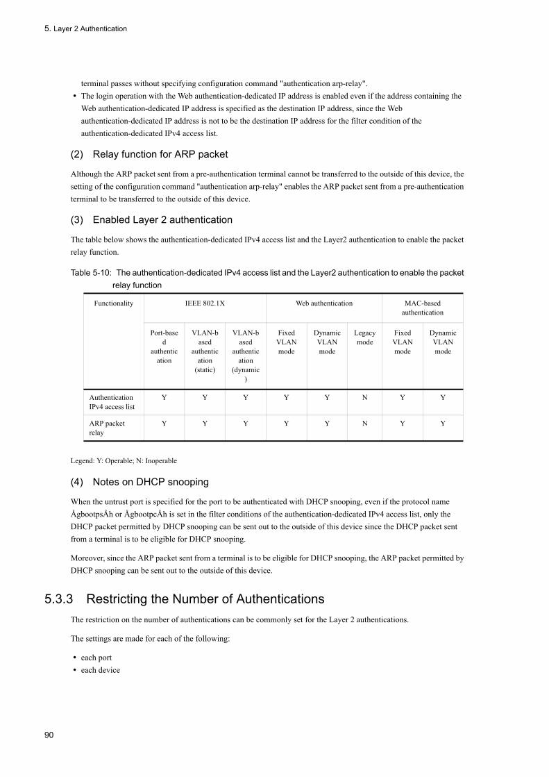
5. Layer 2 Authentication
terminal passes without specifying configuration command "authentication arp-relay".• The login operation with the Web authentication-dedicated IP address is enabled even if the address containing the
Web authentication-dedicated IP address is specified as the destination IP address, since the Web authentication-dedicated IP address is not to be the destination IP address for the filter condition of the authentication-dedicated IPv4 access list.
(2) Relay function for ARP packet
Although the ARP packet sent from a pre-authentication terminal cannot be transferred to the outside of this device, the setting of the configuration command "authentication arp-relay" enables the ARP packet sent from a pre-authentication terminal to be transferred to the outside of this device.
(3) Enabled Layer 2 authentication
The table below shows the authentication-dedicated IPv4 access list and the Layer2 authentication to enable the packet relay function.
Table 5-10: The authentication-dedicated IPv4 access list and the Layer2 authentication to enable the packet relay function
Legend: Y: Operable; N: Inoperable
(4) Notes on DHCP snooping
When the untrust port is specified for the port to be authenticated with DHCP snooping, even if the protocol name ÅgbootpsÅh or ÅgbootpcÅh is set in the filter conditions of the authentication-dedicated IPv4 access list, only the DHCP packet permitted by DHCP snooping can be sent out to the outside of this device since the DHCP packet sent from a terminal is to be eligible for DHCP snooping.
Moreover, since the ARP packet sent from a terminal is to be eligible for DHCP snooping, the ARP packet permitted by DHCP snooping can be sent out to the outside of this device.
5.3.3 Restricting the Number of AuthenticationsThe restriction on the number of authentications can be commonly set for the Layer 2 authentications.
The settings are made for each of the following:
• each port• each device
Functionality IEEE 802.1X Web authentication MAC-based authentication
Port-based
authentication
VLAN-based
authentication
(static)
VLAN-based
authentication
(dynamic)
Fixed VLAN mode
Dynamic VLAN mode
Legacy mode
Fixed VLAN mode
Dynamic VLAN mode
Authentication IPv4 access list
Y Y Y Y Y N Y Y
ARP packet relay
Y Y Y Y Y N Y Y
90

5. Layer 2 Authentication
(1) Restricting the number of authentications for each port
The restriction on the number of authentications can be set for each port by configuration command "authentication max-user". If the number authenticated by each Layer 2 authentication exceeds the specified limits for each port, the authentication results in an error.
(2) Restricting the number of authentications for each device
The restriction on the number of authentications can be set for each device by configuration command "authentication max-user". If the total number authenticated by each Layer 2 authentication exceeds the specified limits for each device, the authentication results in an error.
(3) Layer 2 authentication for which restriction on the number of authentications can be set
The table below shows the Layer 2 authentications for which the restrictions on the number of authentications for each port and the number of authentications for each device can be set.
Table 5-11: Support for limiting authenticated users by layer 2 authentication type
Legend: Y: Supported, N: Not supported
*1
Does not apply to terminals whose communication is restricted.
*2
These modes might be subject to limits on the number of authenticated users depending on how the Switch is configured.
5.3.4 Force AuthenticationWhen the configuration command "authentication force-authorized enable" has been set, once any status of the following occurs, the authentications for all login requests are performed successfully.
• In the RADIUS authentication method, no response has been received from the specified RADIUS server.• In the local authentication method, no authentication data embedded in the device has been registered.
- For the Web authentication, no user has been registered on built-in Web authentication DB.- For the MAC authentication, no MAC address has been registered on built-in Web authentication DB.
Functionality
IEEE 802.1X Web authentication MAC-based authentication
Port-based
authentication
VLAN-based
authentication
(static)
VLAN-based
authentication
(dynamic)
Fixed VLAN mode
Dynamic VLAN mode
Legacy mode
Fixed VLAN mode
Dynamic VLAN mode
Port-level authentication limits
Y*1 Y*1 Y*2 Y Y N Y Y
Switch-level authentication limits
Y*1 Y*1 Y*2 Y Y N Y Y
91

5. Layer 2 Authentication
The user who was forced an authentication can be handled in the same way as the normal successful authentication until the authentication is disabled. The table below shows the authentication modes where the force authentication is enabled:
Table 5-12: Support for forced authentication by authentication mode
Legend: Y: Operable; N: Inoperable
*
In the dynamic VLAN mode, the VLAN ID to be switched by the force authentication should be specified using configuration command "authentication force-authorized vlan". When the configuration command "authentication
force-authorized vlan" is disregarded, it is switched to the VLAN ID of the native VLAN.
[Notes on setting force authentication]
The force authentication may cause the security problem and should be given close consideration to use it.
Example: When using the RADIUS server dedicated to MAC authentication, the following should be noted:
When setting the force authentication, the Web authentication and the MAC authentication on the same port, and the RADIUS server dedicated to the MAC authentication, once the force authentication is operated due to the failure to transmit to the RADIUS server dedicated to MAC authentication, the force authentication operation with the MAC authentication enables the terminal to be authenticated by the Web authentication to transmit without the Web authentication.
5.3.5 Transfer of Authenticated Terminals between PortsThis chapter explains how the port status and the authentication status are changed when the terminal authenticated by the Layer 2 authentication is transferred to the other ports.
The figure below shows the four cases of transferring the authenticated terminals between ports.
Functionality
IEEE 802.1X Web authentication MAC-based authentication
Port-based
authentication
VLAN-based
authentication
(static)
VLAN-based
authentication
(dynamic)
Fixed VLAN mode
Dynamic VLAN mode
Legacy mode
Fixed VLAN mode
Dynamic VLAN mode
Forced authentication
N N N Y Y* N Y Y*
92

5. Layer 2 Authentication
Figure 5-6: Transferring the authenticated terminals between ports
When using MAC VLAN, Case 1 and Case 2 are determined as follows:
Case 1:
If either of the following conditions can be met at the destination port to be authenticated, it could be considered the transfer to the same VLAN.
•The same VLAN ID has been set by configuration command "switchport mac vlan".•The same VLAN ID has already been registered dynamically by the Layer 2 authentication.
In addition, if the VLAN ID of MAC VLAN has not been registered dynamically, it could be considered the transfer to the same VLAN since the VLAN ID where the terminal belongs is generated when transferring the terminal authenticated by the Web authentication or the MAC authentication.
Case 2:
If the following condition can be met at the destination port to be authenticated, it could be considered the transfer to the different VLAN.
•The different VLAN ID has been set by configuration command "switchport mac vlan".
In addition, if the VLAN ID of MAC VLAN has not been registered dynamically, it could be considered the transfer to the different VLAN when transferring the terminal authenticated by IEEE802.1X.
The following explains these four cases for each of the Layer 2 authentications.
(1) Operation on transferring between ports in IEEE802.1X.
The table below provides the port status and the authentication status for each authentication mode when the terminal authenticated by IEEE802.1X is transferred between the ports.
93

5. Layer 2 Authentication
Table 5-13: Behavior when moving IEEE 802.1X-authenticated terminals between ports (port-based authentication)
Table 5-14: Behavior when moving IEEE 802.1X-authenticated terminals between ports (VLAN-based authentication (static))
[Legend]
--: Because VLAN-based authentication (static) takes place at the VLAN level, the VLAN will not contain any non-authenticating
ports.
Scenario Destination port
VLAN User authentication
status
MAC address table of source
port
Authentication status of source port
Ability to communicate
after movement
1 Authenticating port
Same VLAN
Undergoes re-authentication at destination port
Port info. updated Existing authentication canceled
Cannot communicate until re-authenticated
2 Authenticating port
Different VLAN
Undergoes re-authentication at destination port
Not updated Authorized status remains
Cannot communicate until re-authenticated
3 Non-authenticating port
Same VLAN
Authorized status remains
Not updated Authorized status remains
Cannot communicate
4 Non-authenticating port
Different VLAN
Authorized status remains
Not updated Authorized status remains
Can communicate
Scenario Destination port
VLAN User authentication
status
MAC address table of source
port
Authentication status of source port
Ability to communicate
after movement
1 Authenticating port
Same VLAN
Authorization continues
Port info. updated Continues Can communicate
2 Authenticating port
Different VLAN
Undergoes re-authentication at destination port
Not updated Authorized status remains
Cannot communicate until re-authenticated
3 Non-authenticating port
Same VLAN
-- -- -- --
4 Non-authenticating port
Different VLAN
Authorized status remains
Not updated Authorized status remains
Can communicate
94

5. Layer 2 Authentication
Table 5-15: Behavior when moving IEEE 802.1X-authenticated terminals between ports (VLAN-based authentication (dynamic))
[Legend]
--: Because VLAN-based authentication (dynamic) takes place at the VLAN level, the VLAN will not contain any non-authenticating ports.
(2) Operation on transferring between ports in Web authentication
The table below provides the port status and the authentication status for each authentication mode when the terminal authenticated by the Web authentication is transferred between the ports.
Table 5-16: Behavior when moving Web-authenticated terminals between ports (fixed VLAN mode)
Scenario Destination port
VLAN User authentication
status
MAC address table of source
port
Authentication status of source port
Ability to communicate
after movement
1 Authenticating port
Same VLAN
Authorization continues
Port info. updated Continues Can communicate
2 Authenticating port
Different VLAN
Undergoes re-authentication at destination port
Deleted Existing authentication canceled
Cannot communicate until re-authenticated
3 Non-authenticating port
Same VLAN
-- -- -- --
4 Non-authenticating port
Different VLAN
Authorized status remains
Not updated Authorized status remains
Can communicate
Scenario Destination port
VLAN User authentication
status
MAC address table of source
port
Authentication status of source port
Ability to communicate
after movement
1 Authenticating port
Same VLAN
Authorization continues
Port info. updated Continues Can communicate
2 Authenticating port
Different VLAN
Authorized status remains
Not updated Authorized status remains
Cannot communicate until re-authenticated
3 Non-authenticating port
Same VLAN
Authorized status remains
Not updated Authorized status remains
Cannot communicate
4 Non-authenticating port
Different VLAN
Authorized status remains
Not updated Authorized status remains
Can communicate
95

5. Layer 2 Authentication
Table 5-17: Behavior when moving Web-authenticated terminals between ports (dynamic VLAN mode)
Table 5-18: Behavior when moving Web-authenticated terminals between ports (legacy mode)
[Legend]
--: Because Web authentication (legacy mode) takes place at the VLAN level, the VLAN will not contain any non-authenticating ports.
(3) Operation on transferring between ports in MAC authentication
The table below provides the port status and the authentication status for each authentication mode when the terminal authenticated by MAC authentication is transferred between the ports.
Table 5-19: Behavior when moving MAC-authenticated terminals between ports (fixed VLAN mode)
Scenario Destination port
VLAN User authentication
status
MAC address table of source
port
Authentication status of source port
Ability to communicate
after movement
1 Authenticating port
Same VLAN
Authorization continues
Port info. updated Continues Can communicate
2 Authenticating port
Different VLAN
Authorized status remains
Not updated Authorized status remains
Cannot communicate
3 Non-authenticating port
Same VLAN
Authorized status remains
Not updated Authorized status remains
Cannot communicate
4 Non-authenticating port
Different VLAN
Authorized status remains
Not updated Authorized status remains
Can communicate
Scenario Destination port
VLAN User authentication
status
MAC address table of source
port
Authentication status of source port
Ability to communicate
after movement
1 Authenticating port
Same VLAN
Authorization continues
Port info. updated Continues Can communicate
2 Authenticating port
Different VLAN
Authorized status remains
Not updated Authorized status remains
Cannot communicate
3 Non-authenticating port
Same VLAN
-- -- -- --
4 Non-authenticating port
Different VLAN
Authorized status remains
Not updated Authorized status remains
Can communicate
Scenario Destination port
VLAN User authentication
status
MAC address table of source
port
Authentication status of source port
Ability to communicate
after movement
1 Authenticating port
Same VLAN
Authorization continues
Port info. updated Continues Can communicate
96

5. Layer 2 Authentication
*
This operation is performed when broadcast ARP packets are sent after a port is moved from an authenticated terminal. The authenticated status remains without being canceled for packets other than the broadcast ARP packets.
Table 5-20: Behavior when moving MAC-authenticated terminals between ports (dynamic VLAN mode)
*
This operation is performed when broadcast ARP packets are sent after a port is moved from an authenticated terminal. The authenticated status remains without being canceled for packets other than the broadcast ARP packets.
5.3.6 Dead interval function for RADIUS server communicationAfter no response is received from the RADIUS server, the authentication can be performed by communicating with the other RADIUS servers during the time period to be set by the configuration command "authentication radius-server dead-interval". After the specified time period has passed, the authentication can be performed by using the other RADIUS servers to be set first. When no response is received from all the RADIUS servers, the authentication fails to perform even if the communication with the RADIUS server is recovered during the time period to be set by the configuration command "authentication radius-server dead-interval".
Additionally, the following operation commands should be executed in order to restore the communication with the
2 Authenticating port
Different VLAN
Undergoes re-authentication*
Deleted* Existing authentication canceled*
Cannot communicate until re-authenticated*
3 Non-authenticating port
Same VLAN
Authorized status remains
Not updated Authorized status remains
Cannot communicate
4 Non-authenticating port
Different VLAN
Authorized status remains
Not updated Authorized status remains
Can communicate
Scenario Destination port
VLAN User authentication
status
MAC address table of source
port
Authentication status of source port
Ability to communicate
after movement
1 Authenticating port
Same VLAN
Authorization continues
Port info. updated Continues Can communicate
2 Authenticating port
Different VLAN
Authentication status cleared*
Deleted* Existing authentication canceled*
Cannot communicate until re-authenticated*
3 Non-authenticating port
Same VLAN
Authorized status remains
Not updated Authorized status remains
Cannot communicate
4 Non-authenticating port
Different VLAN
Authorized status remains
Not updated Authorized status remains
Can communicate
Scenario Destination port
VLAN User authentication
status
MAC address table of source
port
Authentication status of source port
Ability to communicate
after movement
97

5. Layer 2 Authentication
RADIUS servers to be set first from the failure of the authentication with the dead-interval function:
• Web authenticationÅFclear web-authentication dead-interval-timer• MAC authenticationÅFclear mac-authentication dead-interval-timer
The figure below shows the dead interval functions for RADIUS server communication.
Figure 5-7: The dead interval functions for RADIUS server communication
The figure below shows the Layer 2 authentications corresponding to the dead interval functions for RADIUS server communication.
98

5. Layer 2 Authentication
Table 5-21: The Layer 2 authentications corresponding to the dead interval functions for RADIUS server communication
Legend: Y: Supported; N: Not supported
5.3.7 Operation on setting dot1q for MAC portWhen dot1q has been set for a MAC port by the configuration command Ågswitchport mac dot1q vlanÅh, a Tagged flame is authenticated according to the operation in the static VLAN mode.
An Untagged flame is authenticated according to the operation in the dynamic VLAN mode. The Untagged flame is accommodated on the native VLAN before the authentication, and it is switched to the post-authentication VLAN ID after the successful authentication.
The figure below shows the operation when dot1q has been set for the MAC port.
Functionality
IEEE 802.1X Web authentication MAC-based authentication
Port-based
authentication
VLAN-based
authentication
(static)
VLAN-based
authentication
(dynamic)
Fixed VLAN mode
Dynamic VLAN mode
Legacy mode
Fixed VLAN mode
Dynamic VLAN mode
RADIUS server dead interval functionality
N N N Y Y N Y Y
99

5. Layer 2 Authentication
Figure 5-8: The operation when dot1q has been set for the MAC port
In addition, when the configuration command "mac-authentication dot1q-vlan force-authorized" has been set for the port, the Tagged flame is determined to be excluded from the authentication and it allows to communicate without the MAC authentication. However, since the terminal excluded from the authentication is handled as the authentication terminal with the MAC authentication, the following should be noted:
• The terminal (MAC address) excluded from the authentication is included in the restricted number of authentications to be specified for the port.
• When disabling the terminal excluded from the authentication, the operation log message indicating logout appears. When transferring the terminal excluded from the authentication between ports, once the terminal excluded from the authentication is disabled, the operation log message indicating logout appears.
• The following triggers allow to disable the exclusion from the authentication:- Disabling the exclusion from the authentication by the operation command
When specifying the MAC address of the terminal excluded from the authentication by the operation command "clear mac-authentication auth-state", the exclusion from the authentication is disabled.
When also specifying the option to disable all the terminals authenticated by the MAC authentication using the operation command "clear mac-authentication auth-state", the exclusion from the authentication is disabled.
- Disabling the exclusion from the authentication with a linkdown at the port connecting to the terminal excluded from the authentication
When detecting a linkdown at the port connecting to the terminal excluded from the authentication, the exclusion from the authentication for the terminal connected to the port is disabled.
- Disabling the exclusion from the authentication with a MAC address table aging of the terminal excluded from the authentication
If no access has been made from the terminal excluded from the authentication for about ten minutes after the MAC address table aging time of the terminal excluded from the authentication, the exclusion from the authentication is
100

5. Layer 2 Authentication
disabled.
- Disabling the exclusion from the authentication with the VLAN setting change
When changing the setting for the VLAN where contains the terminal excluded from the authentication by the configuration command, the exclusion from the authentication is disabled.
[Changes in Configuration]
- When removing VLAN
- When suspending VLAN
- Disabling the exclusion from the authentication with the authentication mode switched
When setting to change the configuration by copy command in order to switch the authentication mode, the exclusion from the authentication is disabled.
- Disabling the exclusion from the authentication with the MAC authentication suspended
When removing the setting for the MAC authentication by the configuration command "no mac-authentication system-auth-control" in order to suspend the MAC authentication, the exclusion from the authentication is disabled.
The table below shows the operations for the Layer 2 authentications when setting dot1q for the MAC port.
Table 5-22: Operation of layer 2 authentication with dot1q configured at a MAC port
Frame type IEEE 802.1X Web authentication MAC-based authentication
Untagged frame Subject to VLAN-based authentication (dynamic)
Subject to authentication in dynamic VLAN mode
Subject to authentication in dynamic VLAN mode
Tagged frame Subject to VLAN-based authentication (static)
Cannot be authenticated Subject to authentication in fixed VLAN mode
101

5. Layer 2 Authentication
5.4 Notes on Using Layer 2 Authentication
5.4.1 Notes on Setting This Device and Changing Status
(1) Notes on using set clock command
Since the authentication connection time is based on the device clock, changing the date and time by the operation command "set clock" affects the authentication connection time.
For example, when the clock is advanced by three hours, three hours are added to the elapsed connection time. On the contrary, when the clock is set back by three hours, the authentication time extends by three hours.
5.4.2 Notes on Using RADIUS Server
(1) Notes on specifying the host name for RADIUS server setting
When the RADIUS server is specified by its host name, the following phenomena may occur in the environment where name resolution is disabled for some reason (e.g. connection to the DNS server is disabled):
• When executing operation command- The display speed of the execution result slows down.
- The display is interrupted temporality and then it resumes.
- In IEEE 802.1X, "Connection failed to 802.1X program." appears.
- In the Web authentication and the MAC authentication, "Can't execute." appears.
• When executing configuration command- It may take time to save the configuration or to apply the configuration to the operation.
• When obtaining IEEE 802.1X MIB information by SNMP manager- The response speed slows down, or SNMP reception timeout occurs.
To avoid the phenomena above, it is recommended to use the IPv4 address or the IPv6 address for RADIUS server setting. If it is required to set the server by its host name, ensure that the DNS server can reply.
(2) Notes on disconnection with the RADIUS server in IEEE802.1X
If the communication with the RADIUS server used for the IEEE802.1X is disconnected, or if the RADIUS server specified by the configuration command "radius-server host" does not exist, each login request consumes the timeout period specified by the configuration command "radius-server timeout" and then retries transmission for the number of times specified by the configuration command "radius-server retransmit". As a result, the authentication for each login request takes more time.
When more than one RADIUS server is set, those RADIUS servers are accessed in the order of settings in "radius-server host" command every time login is executed. Therefore, if communication is disabled due to a failure in one of the RADIUS servers previously set, the authentication process takes time at the subsequent servers.
In this case, stop the login operation, and set the RADIUS server without a failure with the "radius-server host" command before resuming the login operation.
102

5. Layer 2 Authentication
5.5 Common Configurations of Layer 2 Authentication
5.5.1 List of Configuration CommandsThe table below lists the configuration commands of the Layer 2 Authentication.
Table 5-23: List of Configuration Commands
Legend: Y: Can be used; --: Cannot be used*: Web authentication is applied in the static VLAN mode and dynamic VLAN mode.
Command name Description Applicable Layer 2 authentication types
IEEE 802.1X
Web* MAC-based
authentication
authentication arp-relay Specified when the ARP packet from the pre-authentication terminal is to be transferred to the outside of this device.
Y Y Y
authentication force-authorized enable Sets the force authentication.
-- Y Y
authentication force-authorized vlan Specifies the VLAN ID to switch the force authentication in the dynamic VLAN mode.
-- Y Y
authentication ip access-group When the packet from the pre-authentication terminal is transferred to the outside of this device, specifies the type of that packet in the IPv4 access list.
Y Y Y
authentication max-user(global)
Sets the limit on the number of authentications for each device.
Y Y Y
authentication max-user(interface)
Sets the limit on the number of authentications for each port.
Y Y Y
authentication radius-server dead-interval Specifies the dead inter-val time for accessing again to the highest pri-ority RADIUS server when no response is re-ceived from the RADI-US server.
-- Y Y
103

5. Layer 2 Authentication
5.5.2 Setting Parameter for Common Configurations Commands of Layer 2 Authentication
(1) Setting to transfer the ARP packet from the pre-authentication terminal to the outside of this device
[Point of setting]
Set the ARP packet transmitted from the pre-authentication terminal to be transferred to the outside of this device.
[Setup using commands]
1. (config)# dinterface gigabitethernet 0/10
(config-if)# web-authentication port
(config-if)# mac-authentication port
(config-if)# authentication arp-relay
(config-if)# exit
Sets the ARP packet to be transferred at the port 1/0/10 to be authenticated by Web authentication and MAC authentication.
(2) Setting IPv4 access list dedicated to authentication
[Point of setting]
Set the IPv4 access list dedicated to the authentication in order to allow to communicate from the pre-authentication terminal to the outside of this device.
[Setup using commands]
1. (config)# ip access-list extended 100
(config-ext-nacl)# permit udp any any eq bootps
(config-ext-nacl)# permit ip any host 10.0.0.1
(config-ext-nacl)# exit
(config)# interface gigabitethernet 0/10
(config-if)# web-authentication port
(config-if)# mac-authentication port
(config-if)# authentication ip access-group 100
(config-if)# exit
Set the IPv4 access list dedicated to the authentication in order to allow to access from the pre-authentication terminal to DHCP packet and IP address 10.0.0.1(DNS server).
(3) Setting force authentication
[Point of setting]
Set the force authentication when no response is received from the RADIUS server, or the built-in Web authentication DB is not registered in the Web authentication and the built-in MAC authentication DB is not registered in the MAC authentication.
[Setup using commands]
1. (config)# authentication force-authorized enable
Sets the force authentication.
104
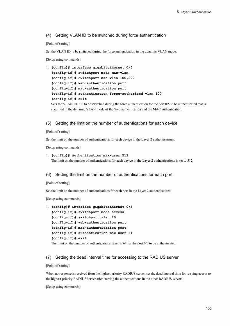
5. Layer 2 Authentication
(4) Setting VLAN ID to be switched during force authentication
[Point of setting]
Set the VLAN ID to be switched during the force authentication in the dynamic VLAN mode.
[Setup using commands]
1. (config)# interface gigabitethernet 0/5
(config-if)# switchport mode mac-vlan
(config-if)# switchport mac vlan 100,200
(config-if)# web-authentication port
(config-if)# mac-authentication port
(config-if)# authentication force-authorized vlan 100
(config-if)# exit
Sets the VLAN ID 100 to be switched during the force authentication for the port 0/5 to be authenticated that is specified in the dynamic VLAN mode of the Web authentication and the MAC authentication.
(5) Setting the limit on the number of authentications for each device
[Point of setting]
Set the limit on the number of authentications for each device in the Layer 2 authentications.
[Setup using commands]
1. (config)# authentication max-user 512
The limit on the number of authentications for each device in the Layer 2 authentications is set to 512.
(6) Setting the limit on the number of authentications for each port
[Point of setting]
Set the limit on the number of authentications for each port in the Layer 2 authentications.
[Setup using commands]
1. (config)# interface gigabitethernet 0/5
(config-if)# switchport mode access
(config-if)# switchport vlan 10
(config-if)# web-authentication port
(config-if)# mac-authentication port
(config-if)# authentication max-user 64
(config-if)# exit
The limit on the number of authentications is set to 64 for the port 0/5 to be authenticated.
(7) Setting the dead interval time for accessing to the RADIUS server
[Point of setting]
When no response is received from the highest priority RADIUS server, set the dead interval time for retrying access to the highest priority RADIUS server after starting the authentications in the other RADIUS servers.
[Setup using commands]
105

5. Layer 2 Authentication
1. (config)# authentication radius-server dead-interval 20
The dead interval time for the RADIUS server is set to twenty minutes.
106

6 General Description of IEEE 802.1XIEEE 802.1X is a function to perform authentication at the second layer of the OSI hierarchical model. This chapter provides an overview of the IEEE 802.1X.
6.1 IEEE 802.1X Overview
6.2 Extended Function Overview
6.3 Notes on Using IEEE 802.1X
107

6. General Description of IEEE 802.1X
6.1 IEEE 802.1X Overview
IEEE 802.1X is a function to restrict unauthorized LAN connection. For this purpose, an authentication server (usually a RADIUS server) is deployed at the backend, imposing the terminal authentication by the authentication server on connection requests before they can enjoy the services from the LANSW module.
The following table lists the components of IEEE 802.1X and their operational outline.
Table 6-1: Components and Operational Outline
In a standard IEEE 802.1X configuration, terminals are connected directly to the ports of the LANSW module. The following figure shows an example of configuring the IEEE802.1X applicable when the Compute Blade 2000 / 500 / 320 server blade is used as an authentication server.
Figure 6-1: Basic IEEE 802.1X Configuration
The LANSW module also supports an extension to authenticate more than one terminal on a single port (i.e., multi and terminal authentication modes). When this extension is used, placing L2 switches or hubs between a terminal and the LANSW module allows the configuration in which the number of terminals is not restricted by the number of ports. With this configuration, the L2 switch placed between the terminals and the LANSW module must support transparent EAPOL. The following figure shows the example of such configuration:
Component Outline of Operation
The LANSW module (authenticator)
Controls the terminal access to the LAN. It also relays authentication information between the terminal and authentication server. EAP Over LAN (EAPOL) is used for communications related to the authentication between a terminal and the LANSW module. The LANSW module and the authentication server exchange authentication information using EAP Over RADIUS. Hereafter in this document, "the LANSW module" or "authenticator" refers to both the LANSW module itself and the authenticator software installed on it.
Terminal (supplicant) Exchanges authentication information with the LANSW module using EAPOL. Hereafter in this document, "terminal" or "supplicant" refers to both the terminal itself and the supplicant software installed on it. "supplicant software" only refers to the software with the supplicant functionality.
Authentication server Authenticates a terminal. The authentication server checks the authentication information of terminal and queries the LANSW module as to whether to allow the requesting terminal to access the services provided by the LANSW module.
108
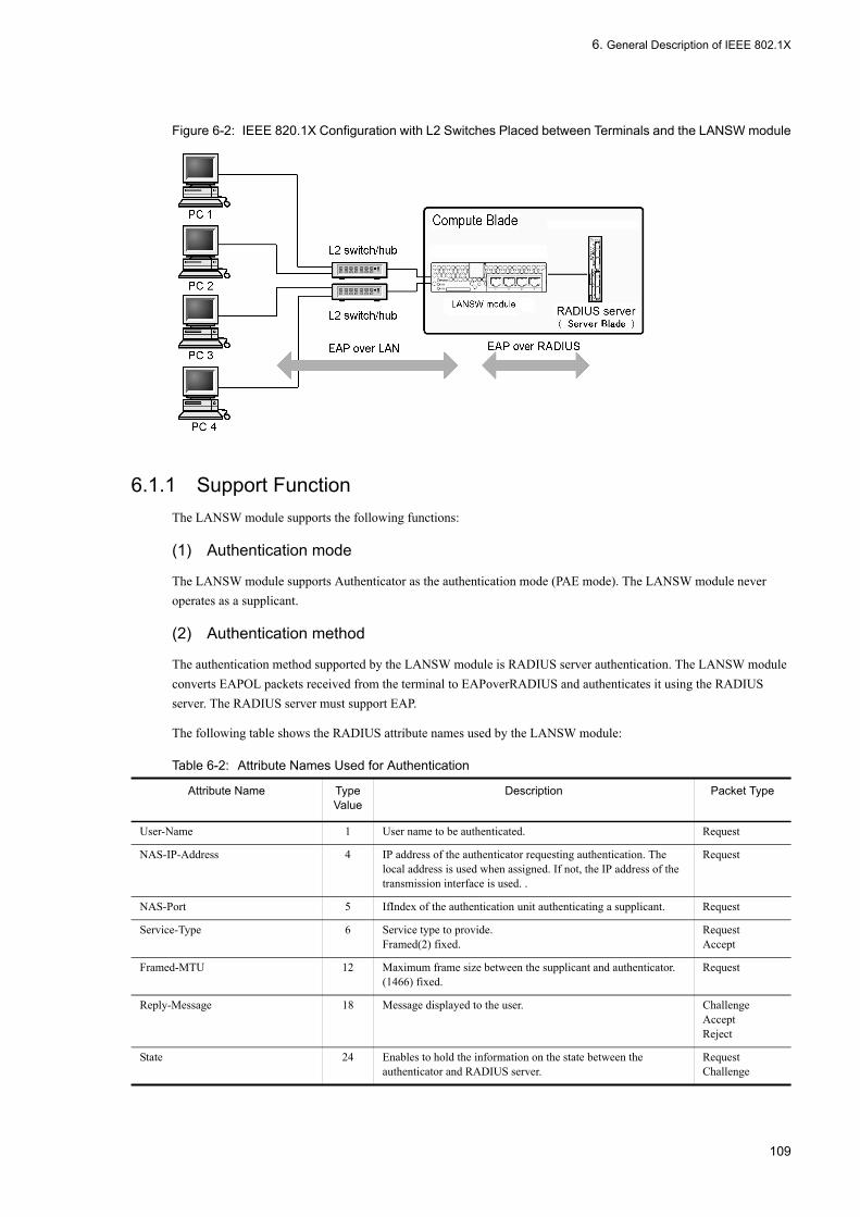
6. General Description of IEEE 802.1X
Figure 6-2: IEEE 820.1X Configuration with L2 Switches Placed between Terminals and the LANSW module
6.1.1 Support FunctionThe LANSW module supports the following functions:
(1) Authentication mode
The LANSW module supports Authenticator as the authentication mode (PAE mode). The LANSW module never operates as a supplicant.
(2) Authentication method
The authentication method supported by the LANSW module is RADIUS server authentication. The LANSW module converts EAPOL packets received from the terminal to EAPoverRADIUS and authenticates it using the RADIUS server. The RADIUS server must support EAP.
The following table shows the RADIUS attribute names used by the LANSW module:
Table 6-2: Attribute Names Used for Authentication
Attribute Name Type Value
Description Packet Type
User-Name 1 User name to be authenticated. Request
NAS-IP-Address 4 IP address of the authenticator requesting authentication. The local address is used when assigned. If not, the IP address of the transmission interface is used. .
Request
NAS-Port 5 IfIndex of the authentication unit authenticating a supplicant. Request
Service-Type 6 Service type to provide.Framed(2) fixed.
RequestAccept
Framed-MTU 12 Maximum frame size between the supplicant and authenticator.(1466) fixed.
Request
Reply-Message 18 Message displayed to the user. ChallengeAcceptReject
State 24 Enables to hold the information on the state between the authenticator and RADIUS server.
RequestChallenge
109

6. General Description of IEEE 802.1X
(3) Authentication algorithm
The table below lists the authentication algorithms supported by the LANSW module.
Session-Timeout 27 Timeout value for response to EAP request sent to a supplicant. Challenge
Called-Station-Id 30 MAC address of bridge or access point. MAC address of the LANSW module (uppercase ASCII separated by "-").
Request
Calling-Station-Id 31 MAC address of the supplicant (uppercase ASCII separated by "-").
Request
NAS-Identifier 32 A string to identify the authenticator (host name string). Request
NAS-Port-Type 61 Type of physical port authenticator uses for user authentication.Ethernet (15) fixed.
Request
Tunnel-Type 64 Tunnel type. Valid only for the VLAN authentication (dynamic).VLAN(13) fixed.
Accept
Tunnel-Medium-Type 65 Protocol for creating a tunnel. Valid only for the VLAN authentication (dynamic).IEEE802(6) fixed.
Accept
Connect-Info 77 String to represent the supplicant connection characteristics.Port authentication:Physical port ("CONNECT Ethernet")CH port ("CONNECT Port-Channel")VLAN authentication (static): ("CONNECT VLAN")VLAN authentication (dynamic): ("CONNECT DVLAN")
Request
EAP-Message 79 Encapsulates the EAP packet. RequestChallengeAcceptReject
Message-Authenticator 80 Used to protect the RADIUS/EAP packet. RequestChallengeAcceptReject
Tunnel-Private-Group-ID 81 String to identify the VLAN. When the packet type is Accept, it indicates the VLAN to be assigned to the authenticated supplicant.Valid only for the VLAN authentication (dynamic).Available strings are as follows:(1) String to indicate VLAN(2) String to indicate "VLAN" + VLAN IDThe string must not include a space (or the VLAN assignment fails).Setting example:For VLAN10For (1), "10"For (2), "VLAN10"
Accept
Acct-Interim-Interval 85 Interim packet transmission interval (sec.).Setting 60 or more transmits Interim packets (setting a value smaller than 60 does not transmit the packets).It is recommended to set the value to 600 or greater. Otherwise, care must be taken because the network traffic increases.
Accept
NAS-Port-Id 87 String to identify the port on which the supplicant is authenticated.Port authentication: "Port x/y", "ChGr x"VLAN authentication (static): "VLAN x"VLAN authentication (dynamic): "DVLAN x"(x and y are substituted by numbers)
Request
Attribute Name Type Value
Description Packet Type
110

6. General Description of IEEE 802.1X
Table 6-3: Supported Authentication Algorithms
(4) RADIUS accounting function
The LANSW module supports the RADIUS accounting function. This enables to trace the user usage status by sending the user accounting information whenever services to a terminal authenticated by IEEE 802.1X authentication is started or stopped. The authentication and accounting load can be distributed by separating the RADIUS authentication server and RADIUS accounting server.
The following table shows the information sent to the RADIUS server when using the RADIUS accounting function:
Table 6-4: Attributes Supported by RADIUS Accounting
Authentication Algorithm Outline
EAP-MD5-Challenge Compares UserPassword with the challenge value.
EAP-TLS Authentication method using the certificate authority.
EAP-PEAP Performs authentication using other EAP authentication algorithm over the EAP-TLS tunnel.
EAP-TTLS Performs authentication using authentication algorithm of other authentication method (such as EAP, PAP, CHAP) over the EAP-TLS tunnel.
Attribute Name Type Value
Description Transmission Depending on Accounting Type
start stop Interim-Update
User-Name 1 User name to be authenticated. Y Y Y
NAS-IP-Address 4 IP address of the authenticator requesting authentication.The local address is used when assigned. If not, the IP address of the transmission interface is used. .
Y Y Y
NAS-Port 5 IfIndex of the authentication unit authenticating a supplicant.
Y Y Y
Service-Type 6 Service type to provide.Framed(2) fixed.
Y Y Y
Calling-Station-Id 31 MAC address of the supplicant (uppercase ASCII separated by "-").
Y Y Y
NAS-Identifier 32 String to identify the authenticator. (Host name string) Y Y Y
Acct-Status-Type 40 Accounting request type.Start(1), Stop(2), Interim-Update(3)
Y Y Y
Acct-Delay-Time 41 Accounting information transmission delay (sec.). Y Y Y
Acct-Input-Octets 42 Accounting information (number of received octets).(0) fixed.
- Y Y
Acct-Output-Octets 43 Accounting information (number of transmitted octets).(0) fixed.
- Y Y
Acct-Session-Id 44 ID to identify the accounting information. Y Y Y
Acct-Authentic 45 Authentication method (RADIUS(1), Local(2), Remote(3)).
Y Y Y
Acct-Session-Time 46 Accounting information (session duration). - Y Y
Acct-Input-Packets 47 Accounting information (number of received packets).(0) fixed.
- Y Y
111
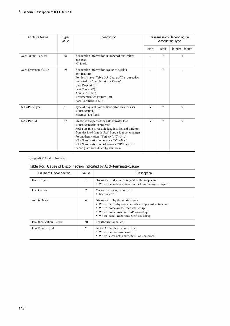
6. General Description of IEEE 802.1X
(Legend) Y: Sent -: Not sent
Table 6-5: Cause of Disconnection Indicated by Acct-Terminate-Cause
Acct-Output-Packets 48 Accounting information (number of transmitted packets).(0) fixed.
- Y Y
Acct-Terminate-Cause 49 Accounting information (cause of session termination).For details, see "Table 6-5: Cause of Disconnection Indicated by Acct-Terminate-Cause".User Request (1),Lost Carrier (2),Admin Reset (6),Reauthentication Failure (20),Port Reinitialized (21)
- Y -
NAS-Port-Type 61 Type of physical port authenticator uses for user authentication.Ethernet (15) fixed.
Y Y Y
NAS-Port-Id 87 Identifies the port of the authenticator that authenticates the supplicant.PAS-Port-Id is a variable length string and different from the fixed-length NAS-Port, a four octet integer.Port authentication: "Port x/y", "ChGr x"VLAN authentication (static): "VLAN x"VLAN authentication (dynamic): "DVLAN x"(x and y are substituted by numbers)
Y Y Y
Cause of Disconnection Value Description
User Request 1 Disconnected due to the request of the supplicant.• Where the authentication terminal has received a logoff.
Lost Carrier 2 Modem carrier signal is lost.• Internal error
Admin Reset 6 Disconnected by the administrator.• Where the configuration was deleted per authentication.• Where "force-authorized" was set up.• Where "force-unauthorized" was set up.• Where "force-authorized-port" was set up.
Reauthentication Failure 20 Reauthorization failed.
Port Reinitialized 21 Port MAC has been reinitialized.• Where the link was down.• Where "clear dot1x auth-state" was executed.
Attribute Name Type Value
Description Transmission Depending on Accounting Type
start stop Interim-Update
112

6. General Description of IEEE 802.1X
6.2 Extended Function Overview
The LANSW module has extended the standard functionality of the IEEE 802.1X. The following outlines the extended functions.
6.2.1 Authentication ModeThe LANSW module provides the IEEE 820.1X function with two basic authentication modes and three authentication sub modes. The basic authentication mode indicates the unit of authentication and the authentication sub mode specifies the authentication method. Options are also available for each of the basic authentication modes and authentication sub modes. The following table shows the correlation between each authentication mode:
Table 6-6: Correlation between Authentication Modes and Options
(Legend) -: Not applicable
As for the IEEE 802.1X function, the LANSW module also assumes a channel group as a single bundled port. When describing this function, "port" refers to both of a normal port and channel group.
(1) Basic authentication mode
The following describes the basic authentication modes supported by the LANSW module.
(a) Port authentication
In this mode, authentication is controlled on a physical port or channel group basis. Ports are the standard IEEE 802.1X authentication unit. The authentication mode does not support EAPOL frames with the IEEE 802.1Q VLAN tag. EAPOL frames with the IEEE 802.1Q VLAN tag are discarded when received.
The following figure shows the example of the port authentication configuration:
Basic Authentication Mode Authentication Sub-mode Authentication Option
Port authentication Single mode -
Multi mode -
Terminal authentication mode Option to exclude specific terminals from authentication
Option to limit the number of authentication terminals
VLAN authentication (static) Terminal authentication mode Option to exclude specific terminals from authentication
Option to exclude specific ports from authentication
Option to limit the number of authentication terminals
VLAN authentication (dynamic) Terminal authentication mode Option to exclude specific terminals from authentication
Option to limit the number of authentication terminals
Default authentication VLAN
113

6. General Description of IEEE 802.1X
Figure 6-3: Configuration Example for Port Authentication
(b) VLAN authentication (static)
The authentication is controlled on a VLAN basis. It supports EAPOL frames with the IEEE 802.1Q VLAN tag. This mode is used when adding IEEE 802.1Q VLAN tags using an L2 switch placed between the terminal and the LANSW module. EAPOL frames without the tag are assumed to have been received by the native VLAN set up on the port.
The following figure shows the example of the VLAN authentication (static) configuration:
Figure 6-4: Configuration Example for VLAN Authentication (Static)
(c) VLAN authentication (dynamic)
The authentication is controlled on a terminal which is the member of a MAC VLAN. It does not support EAPOL frames with the IEEE 802.1Q VLAN tag. Such frame are discarded when received.
Predefined MAC VLAN trunk ports and access ports are assumed as excluded from authentication.
Successfully authenticated terminals dynamically switch over between VLANs according to the VLAN information (VLAN ID of MAC VLAN) provided by the RADUS server, the authentication server.
The following figure shows the example of VLAN authentication (dynamic) configuration and operations:
114

6. General Description of IEEE 802.1X
Figure 6-5: Configuration Example for VLAN Authentication (Dynamic)
115
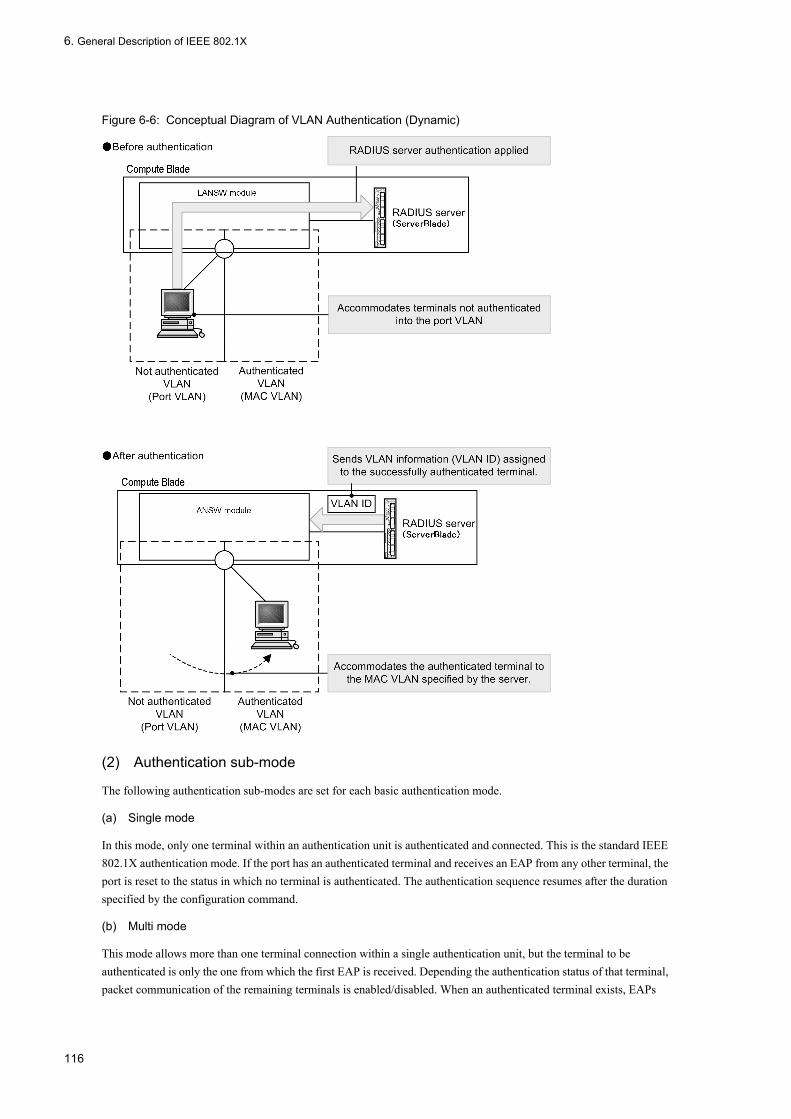
6. General Description of IEEE 802.1X
Figure 6-6: Conceptual Diagram of VLAN Authentication (Dynamic)
(2) Authentication sub-mode
The following authentication sub-modes are set for each basic authentication mode.
(a) Single mode
In this mode, only one terminal within an authentication unit is authenticated and connected. This is the standard IEEE 802.1X authentication mode. If the port has an authenticated terminal and receives an EAP from any other terminal, the port is reset to the status in which no terminal is authenticated. The authentication sequence resumes after the duration specified by the configuration command.
(b) Multi mode
This mode allows more than one terminal connection within a single authentication unit, but the terminal to be authenticated is only the one from which the first EAP is received. Depending the authentication status of that terminal, packet communication of the remaining terminals is enabled/disabled. When an authenticated terminal exists, EAPs
116

6. General Description of IEEE 802.1X
received from any other terminals are ignored.
(c) Terminal authentication mode
This mode allows more than one terminal to be connected within a single authentication unit and individual terminals (identified by the source MAC address) are authenticated. When an authenticated terminal exists and an EAP is received from another terminal, the authentication sequence with that terminal starts.
(3) Authentication mode options
The following options are available for the authentication mode/authentication sub-mode:
(a) Option to exclude specific terminals from authentication
For the terminals that have been assigned with the MAC address by the static MAC address learning and MAC VLAN functions, this option allows communication without authentication. This option is useful to exclude specific terminals (devices such as printers that cannot operate as supplicant, or servers that do not need to be authenticated) from authentication. It is only available in the terminal authentication mode.
The following figure shows a configuration example for excluding a specific terminal from the VLAN authentication (dynamic):
Figure 6-7: Configuration Example for Excluding a Terminal from VLAN Authentication (Dynamic)
(b) Option to exclude specific ports from authentication
This option allows to specify the physical port number or channel group number under which terminals can be connected without authentication. It is only available for the VLAN authentication (static) and should be used if desired ports reside on the target VLAN for authentication.
If more than one VLAN authentication (static) VLAN has been set up within one port, the port on all the VLANs is excluded from authentication.
The following figure shows a configuration example for excluding a port from the VLAN authentication (static):
117

6. General Description of IEEE 802.1X
Figure 6-8: Configuration Example for Excluding a Port from VLAN Authentication (Static)
(c) Option to limit the number of authentication terminals
This option is used to restrict the maximum number of terminals that one authentication unit can accommodate. It is available only for the terminal authentication mode. The following table lists the set values per authentication unit:
Table 6-7: Option to Limit the Number of Authentication Terminals
(d) Default authentication VLAN function
The default authentication VLAN function allows the port VLAN to accommodate terminals which cannot be accommodated in the MAC VLAN due to not supporting 802.1X, or other reasons. If the port VLAN or default VLAN has been set up for a port with the VLAN authentication (dynamic) enabled, the VLAN operates as the default authentication VLAN. In the following conditions, the terminal should be placed on the default authentication VLAN.
• Terminals not supporting 802.1X• Terminals supporting 802.1X, but not authenticated• Terminals failed in authentication or reauthentication• VLAN ID specified by the RADIUS server is not MAC VLAN• VLAN ID specified by the RADIUS server is not set up for the port
6.2.2 Option for Switching Terminal Detecting OperationTo trigger the terminal authentication, the LANSW module multicasts EAP requests or IDs at the intervals specified using "tx-period". If the Authentication sub mode has been set to the terminal authentication mode, the authentication unit may have more than one terminal. Thus, the LANSW module continues to transmit the EAP request or ID by default until all the terminals complete their authentication. If a considerably large number of terminals present in a authentication unit, the authentication process by the terminal responding to the EAP request and ID may impose excessive load on systems. To reduce the load on the LANSW module, the response from the authenticated terminal bypasses the authentication sequence partially.
Authentication Mode Initial Value Minimum Value Maximum Value
Port authentication 64 1 64
VLAN authentication (static) 256 1 256
VLAN authentication (dynamic) 256 1 256
118

6. General Description of IEEE 802.1X
Note, however, this partial omission of the authentication sequence may cause a problem that some supplicant software disconnect the communication with the authenticated terminal. For this reason, the option that switches over the operation on the authenticated terminals is provided. This option can be set on "supplicant-detection" and the following three types of operations are available:
(1) shortcut
This partially omits the authentication sequence triggered by an EAP request or ID for an authenticated terminal to relieve the LANSW module from excessive loads. In this mode, some supplicant software may disconnect communication with the authenticated terminal during authentication triggered by an EAP request or ID. To avoid this, set this option to "disable" if the supplicant software can automatically transmit the EAP-Start. If it is not the case, set this option to "full".
(2) disable
This interrupts to transmit the EAP request or ID if more than one authenticated terminal exists. If this mode is used for supplicant software that does not automatically transmit, the trigger to start authentication is missed and the authentication cannot be started. The Windows-based supplicant software does not automatically transmit the EAP start, however this activity can be altered by modifying SupplicantMode for the registry. For details on the registry, see the Microsoft public WWW sites or appropriate open technical documents. Take particular care to edit the registry settings, or Windows may become unable to boot up. It is recommended that you take a backup of the original registry information before editing it.
(3) full
This assures not to omit any part of the authentication sequence triggered by an EAP request or ID for an authenticated terminal. Set this mode when using a supplicant software which does not send EAP-Start voluntarily and another supplicant software which causes problems when omitting authentication sequence together. Note that when using this mode, the number of terminals that can be connected is limited.
It is available only in the terminal authentication mode. The following figures show each of their operation sequences:
119

6. General Description of IEEE 802.1X
Figure 6-9: Sequence of EAP request/identity for "shortcut", "disable" or "full"
6.2.3 Terminal Requested Reauthentication Suppressing FunctionThis suppresses reauthentication triggered by the EAPOL-Start sent from a terminal. This protects the LANSW module from being overloaded by considerable reauthentication that may be caused by reauthentication requests frequently submitted by many terminals within a short period. If this option is set, reauthentication of terminals is performed periodically at the intervals specified with the configuration.
120

6. General Description of IEEE 802.1X
6.2.4 RADIUS Server Connecting Function
(1) Connection with RADIUS server
Up to four RADIUS servers can be specified. Although either of the IPv4 address or host name of the server can be specified, it is recommended to use the IPv4 address in IEEE 802.1X. When specifying the host name, follow the note described in "6.3.2 Notes on Using IEEE 802.1X, (6) Note on specifying the host name for RADIUS server setting". For connection between the LANSW module and RADIUS server, use the authentication exceptive port.
Connection to RADIUS servers conforms to the order of configuration. If a connection fails, connection to the next RADIUS server is attempted. If connections to all RADIUS servers fail, an EAP failure is issued to the terminal and the authentication sequence is canceled.
If communication timeout is detected during the authentication sequence after connection to the RADIUS server, an EAP failure is issued to the terminal and the authentication sequence is ended.
(2) Setup for dynamic assignment with VLAN authentication (dynamic)
When performing VLAN authentication (dynamic) supported by the LANSW module, the following attributes must be set for the RADIUS server. For details of the attributes, see "Table 6-2: Attribute Names Used for Authentication".
• Tunnel-Type• Tunnel-Medium-Type• Tunnel-Private-Group-Id
(3) Setup for identification of the LANSW module in RADIUS server
The RADIUS protocol regulates that the source IP address of a request packet to be used as the key to identify the RADIUS client (NAS). The LANSW module uses the following addresses for the source IP addresses of request packets:
• If a local address has been set up, the local address is used as the source IP address.• While no local address has been set up, the IP address of a transmission interface is used as the source IP address.
When the LANSW module has a local address assigned, register the IP address specified as the local address with the RADIUS server. Even if the interface to communicate with the RADIUS server cannot be identified, the IP address of the LANSW module registered with the RADIUS server can be identified instead.
6.2.5 EAPOL Forwarding FunctionThis function relays EAPOL frame when IEEE 802.1X is disabled on the LANSW module. Since the target MAC address of EAPOL frames is reserved for IEEE 802.1D, EAPOL frames are normally not forwarded but this function allows forwarding the frames if IEEE 802.1X is not used. It is available when using the LANSW module as an L2 switch between another authenticator and a terminal.
For examples on configuring this function, see "Configuration Settings, Vol. 1, 18.6 Configuration of L2 Protocol Frame Transparent Function".
6.2.6 Limit on the number of terminals that can be authenticatedYou can limit the number of authenticated users at the device level and at the port level. For details, see 5.3 Common Functions for Layer 2 Authentication.
121

6. General Description of IEEE 802.1X
6.2.7 Moving authenticated terminals between portsFor details about how the switch behaves when you move an authenticated terminal between ports, see 5.3 Common Functions for Layer 2 Authentication.
6.2.8 VLAN-based authentication (dynamic) operation modesTerminals authenticated by VLAN-based authentication (dynamic) do not count against the maximum number of authenticated users. However, when a port that performs VLAN-based authentication (dynamic) authentication has any of the characteristics listed below, terminals attached to that port count against the maximum number of authenticated users, and can no longer use the authentication default VLAN. For details about authentication session limits, see 5.3.3
Restricting the Number of Authentications.
• Web authentication (dynamic VLAN mode) is configured• MAC-based authentication is configured• Dot1q is configured in a VLAN with a VLAN-based authentication (static) policy• An authentication IPv4 access list is specified• The port is configured to relay ARP packets from unauthenticated terminals• auto is specified as the terminal detection behavior switching option (affects all ports)
6.2.9 Blocking traffic from authenticated terminalsWith port-based authentication (in terminal authentication mode) or VLAN-based authentication (static), you can apply a filter that blocks the traffic generated by an authenticated terminal. For details about how to configure this functionality, see 6.2.4 RADIUS Server Connecting Function.
Note that the blocked terminal does not count against the maximum number of authenticated users. For details about the limits for authenticated users, see 5.3.3 Restricting the Number of Authentications.
122

6. General Description of IEEE 802.1X
6.3 Notes on Using IEEE 802.1X
6.3.1 Coexistence of IEEE 802.1X and Other FunctionsThe following table lists the coexistence specifications of the IEEE 802.1X and other functions:
Table 6-8: IEEE 802.1X Functional Compatibility with Other Functions
The following table lists the coexistence specifications of the IEEE 802.1X functions, port and the VLAN types:
Table 6-9: IEEE 802.1X Functional Compatibility with Port and VLAN Type
(Legend) Y: Coexistence allowed Y/N: Coexistence partially allowed N: Coexistence not allowed
*1If the VLAN ID specified for the access port is a MAC VLAN, co-existence is not allowed.
*2Access port for VLAN authentication (dynamic) is automatically excluded from authentication.
*3When a VLAN subject to authentication and VLAN not subject to authentication are set on the same port, communication on the latter is disabled. However, this is not the case when the authentication option specifies the port to be excluded from authentication.
Function Name Compatibility Specifications
Spanning tree Authentication on ports with the status fixed to "Forwarding" can be enabled. Authentication on any other ports must be disabled.The ports the status fixed to "Forwarding" are as follows:• PortFast port• Root bridge port
Sending/Receiving BPDU and topology calculation of the spanning tree are performed regardless of the IEEE 802.1X authentication state.
GSRP It cannot be used together with IEEE 802.1X on the LANSW module.
VLAN tunneling It cannot be used together with IEEE 802.1X on the LANSW module.
VRRP Authentication are enabled on a VLAN without VRRP setting and a port other than those with VLAN operating VRRP. In the following cases, 802.1X authentication is disabled. • For VLAN authentication (static), VLAN with VRRP operating• For VLAN authentication (dynamic), authentication using authentication default VLAN
and MAC VLAN in VLAN with VRRP operating• For port authentication, port for which VLAN with VRRP operating is set
OADP, CDP Cannot transmit transparently.
Function Name Port Authentication VLAN Authentication (Static)
VLAN Authentication (Dynamic)
Port VLAN Y Y N
Default VLAN Y N N
Protocol VLAN N N N
MAC VLAN N N Y
Access port Y/N*1 Y Y*2
Trunk port N Y*3 Y*4
Protocol port N N N
MAC port N N Y
Tunneling port N N N
123

6. General Description of IEEE 802.1X
*4VLAN authentication (dynamic) trunk ports are automatically excluded from authentication.
6.3.2 Notes on Using IEEE 802.1X
(1) Setting aging time for MAC address learning with VLAN authentication (dynamic)
When using VLAN authentication (dynamic), do not set the aging time of the MAC address entry to zero (0) for the port VLANs assigned as the MAC VLAN and default authentication VLAN. If the aging time is set to 0 and VLAN switchover occurs, the MAC address entry of the previous VLAN to which the terminal belongs is not cleared, resulting in unnecessary MAC address entries accumulated. In this case, use the "clear-mac-address-table" command to clear the address from the previous VLAN.
(2) Indications of MAC address table for authenticated terminals
The type of terminals that have been authenticated by the port authentication or VLAN authentication (static) are flagged on the MAC address table as "Static". The terminals authenticated by the VLAN authentication (dynamic) are flagged as "Dynamic".
(3) Moving authenticated terminals among ports
If an authenticated terminal is moved to another port not subject to the same VLAN authentication, it is not until that the authenticated state is released from the terminal that communications are enabled for it. Execute "clear dot1x auth-state" to release the authenticated state on the terminal.
(4) Changing timer value
If the timer value ("x-period", "reauth-period", "supp-timeout", "quiet-period", "keep-unauth") is changed, the change is not applied until the current timer per authentication unit is timed out and set to zero (0). To immediately apply the change, execute the "clear dot1x auth-state" command to release the authentication state.
(5) Notes on placing L2 switch between terminal and the LANSW module
Since the responses from a terminal are generally multicasted, if a L2 switch is placed between the terminal and the LANSW module, the EAPOL frames on the response from the terminal are transferred to all the port within the same VLAN where the L2 switch exits. Thus configuring the VLAN of the L2 switch as follows forces the EAPOL frames from one terminal to be delivered to more than one port on the LANSW module, causing authentication of the terminal performed on more than one port. This causes unstable authentication operations, which may disconnect communication or, disable authentication.
• Connecting the port set on the same VLAN of an L2 switch to more than one port on which the LANSW module performs authentication
• Connecting the port set on the same VLAN of an L2 switch to the port on which more than one system performs authentication
The following figures illustrate the prohibited and correct configuration when placing an L2 switch between a terminal and the LANSW module:
124
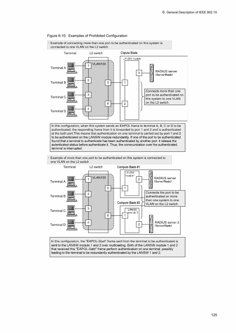
6. General Description of IEEE 802.1X
Figure 6-10: Examples of Prohibited Configuration
125

6. General Description of IEEE 802.1X
Figure 6-11: Example of Correct Configuration
(6) Note on specifying the host name for RADIUS server setting
When the RADIUS server used in IEEE 802.1X is specified by its host name, the following phenomena may occur in the environment where name resolution is disabled for some reason (e.g. connection to the DNS server is disabled):
When executing IEEE 802.1X operation command• The display speed of the execution result slows down.• The display is interrupted temporality and then it resumes.• "Connection failed to 802.1X program." appears.
When executing IEEE 802.1X configuration command• It may take time to save the configuration or to apply the configuration to the operation.
When obtaining IEEE 802.1X MIB information by SNMP manager• The response speed slows down, or SNMP reception timeout occurs.
To avoid the phenomena above, it is recommended to use the IPv4 address for RADIUS server setting in IEEE 802.1X. If it is required to set the server by its host name, ensure that the DNS server can reply.
(7) Notes on specification of MAC VLAN as access port• If a MAC VLAN authenticated by VLAN (dynamic) is specified as an access port, an EAPOL frame is sent from the
specified port on the LANSW module. When the user side gives an authentication response to the EAPOL frame, the specified port is dealt with as an authentication exceptive port. Therefore, communication via the specified port is allowed whether or not authentication is successful.
• Although port authentication can be set for the interface that specifies a MAC VLAN as an access port, co-existence of VLAN authentication is impossible therefore port authentication must not be used.
(8) Note on transmission interval of Interim packet
When using RADIUS Accounting Interim packet, it is recommended to set the transmission interval to 600 or greater in the Acct-Interim-Interval attribute for RADIUS packet. Otherwise, care must be taken because the number of Interim
126

6. General Description of IEEE 802.1X
packets to be sent becomes equivalent to the number of authenticated terminal, which increases the load on RADIUS server and the network.
(9) Precautions required when you set the "mac-based-vlan static-only" configuration command for the MAC VLAN
You cannot set IEEE802.1X if you have set the "mac-based-vlan static-only" configuration command in the MAC VLAN
(10) Precautions regarding the coexistence of static entry registration MAC and the VLAN unit authentication (dynamic) mode
For an interface in the MAC VLAN mode in the VLAN having set the VLAN unit authentication (dynamic) mode, the particular terminal cannot process authentication normally if the "mac-address-table static" command is used to register the static entry in the address table
127

6. General Description of IEEE 802.1X
128

7 Configuration and Operation of IEEE 802.1XIEEE 802.1X is a function to perform authentication at the second layer of the OSI hierarchical model. This chapter discusses how the IEEE 802.1X function works.
7.1 Configuration of IEEE 802.1X
7.2 IEEE 802.1X Operations
129

7. Configuration and Operation of IEEE 802.1X
7.1 Configuration of IEEE 802.1X
7.1.1 List of Configuration CommandsThe following table lists the configuration commands related with the IEEE 802.1X function:
Table 7-1: List of Configuration Commands
Command Description
aaa accounting dot1x default Sets up IEEE 802.1X to use the RADIUS server for accounting.
aaa authentication dot1x default Sets up IEEE 802.1X to perform user authentication for IEEE 802.1X on the RADIUS server.
aaa authorization network default Sets up IEEE 802.1X to perform VLAN authentication (dynamic) in accordance with the VLAN information provided by the RADIUS server.
dot1x force-authorized-port Sets up ports or channel groups which are relieved of authentication for communications, within the VLAN authentication (static) configuration.
dot1x ignore-eapol-startdot1x vlan ignore-eapol-startdot1x vlan dynamic ignore-eapol-start
Sets up IEEE 802.1X not to send an EAP request or ID when receiving an EAPOL-Start from a supplicant.
dot1x logging enable Enables the output of IEEE 802.1X operation log information to a syslog server.
dot1x loglevel Specifies the message level to record operation log messages.
dot1x max-reqdot1x vlan max-reqdot1x vlan dynamic max-req
Sets up the maximum number of times to send EAP requests or IDs repeatedly to a supplicant that does not respond.
dot1x max-supplicantdot1x vlan max-supplicantdot1x vlan dynamic max-supplicant
Sets up the maximum number of authentication terminals within an authentication unit.
dot1x multiple-hostsdot1x multiple-authentication
Sets up the authentication sub mode for the port authentication.
dot1x port-control Enables the port authentication.
dot1x reauthenticationdot1x vlan reauthenticationdot1x vlan dynamic reauthentication
Sets up enabling/disabling the reauthentication of authenticated terminals.
dot1x supplicant-detectiondot1x vlan supplicant-detectiondot1x vlan dynamic supplicant-detection
Sets up the options to control the terminal detecting operations for the selected terminal authentication mode as the authentication sub mode.
dot1x system-auth-control Enables the IEEE 802.1X function.
dot1x timeout keep-unauth For the port authentication single mode, this sets up the time over which to keep the communication shutdown state on the specific port when authentication request submitted by more than one terminal are detected.
dot1x timeout quiet-perioddot1x vlan timeout quiet-perioddot1x vlan dynamic timeout quiet-period
Sets up the latency time until the authentication resumes for the supplicant that failed in an authentication (or reauthentication).
dot1x timeout reauth-perioddot1x vlan timeout reauth-perioddot1x vlan dynamic timeout reauth-period
Sets up the time interval to reauthenticate the authenticated terminal.
dot1x timeout server-timeoutdot1x vlan timeout server-timeoutdot1x vlan dynamic timeout server-timeout
Sets the latency time waiting for the response from the authentication server.
130

7. Configuration and Operation of IEEE 802.1X
7.1.2 Basic Configuration of IEEE 802.1XThis subsection describes the basic authentication mode setting of IEEE 802.1X function.
(1) Setup enabling IEEE 802.1X
[Point of setting]Enable the IEEE 802.1X function in the global configuration mode. This command must be executed to enable any other IEEE 802.1X commands.
[Setup using commands]
1. (config)# dot1x system-auth-control
Enables the IEEE 802.1X function.
(2) Setup for port authentication
This sets up a physical port or channel group for authentication.
[Point of setting]Set an access port and enable the port authentication on it. It also sets up the authentication sub mode, as required. If the authentication sub mode is omitted, the single mode is specified by default.
[Setup using commands]
1. (config)# interface gigabitethernet 0/1
(config-if)# switchport mode access
Sets the "access" mode for port 0/1.
2. (config-if)# dot1x multiple-authentication
Sets the authentication sub mode to the terminal authentication mode.
3. (config-if)# dot1x port-control auto
Enables the port authentication.
(3) Setup for VLAN authentication (static)
This sets up a port VLAN for authentication.
[Point of setting]
dot1x timeout supp-timeoutdot1x vlan timeout supp-timeoutdot1x vlan dynamic timeout supp-timeout
Sets up the latency time to wait for the response to the EAP request or ID transmitted to the supplicant.
dot1x timeout tx-perioddot1x vlan timeout tx-perioddot1x vlan dynamic timeout tx-period
Sets up the time interval to submit EAP requests or IDs.
dot1x vlan enable Enables the VLAN authentication (static).
dot1x vlan dynamic enable Enables the VLAN authentication (dynamic).
dot1x vlan dynamic radius-vlan Sets up the VLAN that allows dynamic VLAN assignment for the VLAN authentication (dynamic), which refers to the VLAN information provided by the RADIUS server.
Command Description
131
7. Configuration and Operation of IEEE 802.1X
Set a port VLAN for authentication and enable the VLAN authentication (static) on it.
[Setup using commands]
1. (config)# vlan 10
(config-vlan)# state active
(config-vlan)# exit
Sets a port VLAN for VLAN ID 10.
2. (config)# dot1x vlan 10 enable
Enables the VLAN authentication (static) on VLAN ID 10.
(4) Setup for VLAN authentication (dynamic)
This sets up a MAC VLAN for authentication.
[Point of setting]Set a MAC VLAN for authentication and enable the VLAN authentication (dynamic) on it.To register the terminal successfully authenticated by VLAN authentication (dynamic) according to the VLAN information specified by the RADIUS server, the configuration command "aaa authorization network default" must be also set.
[Setup using commands]
1. (config)# vlan 100 mac-based
(config-vlan)# state active
(config-vlan)# exit
Sets the MAC VLAN for VLAN ID 100.
2. (config)# dot1x vlan dynamic radius-vlan 100
Sets the VLAN authentication (dynamic) for VLAN ID 100.
3. (config)# dot1x vlan dynamic enable
Enables the VLAN authentication (dynamic).
7.1.3 Setting Authentication Mode OptionsThis subsection describes how to set the authentication mode options and parameters.
(1) Setting exclude authentication terminal options
This sets up MAC addresses for the terminals that are relieved of authentication for communication, including terminals without the IEEE 802.1X functions.
[Point of setting]Register static entries on the MAC address table for the port authentication or VLAN authentication (static). For the VLAN authentication (dynamic), register MAC addresses on MAC VLANs.
[Setup using commands] (Port authentication)
1. (config)# interface gigabitethernet 0/1
(config-if)# switchport mode access
(config-if)# switchport access vlan 10
132

7. Configuration and Operation of IEEE 802.1X
(config-if)# dot1x multiple-authentication
(config-if)# dot1x port-control auto
(config-if)# exit
Assigns VLAN ID 10 to port 1/0 and set up the port authentication with the authentication sub mode, the terminal authentication mode.
2. (config)# mac-address-table static 0012.e200.0001 vlan 10 interface
gigabitethernet 0/1
Sets MAC address (0012.e200.0001) static to allow it communication without authentication on port 0/1 VLAN ID 10.
[Setup using commands] (VLAN authentication (dynamic))
1. (config)# vlan 100 mac-based
(config-vlan)# mac-address 0012.e200.0001
(config-vlan)# exit
Sets a MAC address that is permitted for communication on MAC VLAN with VLAN ID 100. The terminal can communicate through VLAN ID 100 without the IEEE 802.1X authentication.
2. (config)# dot1x vlan dynamic radius-vlan 100
(config)# dot1x vlan dynamic enable
Sets and enables the VLAN authentication (dynamic) for VLAN ID 100.
(2) Setting exclude authentication port options
[Point of setting]Among the ports belonging to the VLAN with VLAN authentication (static), specify the port to enable the communication without authentication. If more than one VLAN has been set up for the port, communication is enabled on all the VLAN without authentication.
[Setup using commands]
1. (config)# interface gigabitethernet 0/1
(config-if)# dot1x force-authorized-port
Sets port 0/1 that is the member of the VLAN with the VLAN authentication (static) enabled to communicate without authentication.
[Note]If a VLAN set for the VLAN authentication (static) is added to the port excluded from authentication, communication through the port may be interrupted temporarily.
(3) Setup for restricting the number of terminals to be authenticated
[Point of setting]Set the maximum number of terminals to be allowed for authentication in each authentication mode. For the port authentication, this setting is valid if the authentication sub mode is set to terminal authentication mode.
[Setup using commands] (Port authentication)
1. (config)# interface gigabitethernet 0/1
(config-if)# dot1x multiple-authentication
133
7. Configuration and Operation of IEEE 802.1X
(config-if)# dot1x port-control auto
(config-if)# dot1x max-supplicant 50
Sets the maximum number of the terminals to 50, which are subject to the authentication by port 1/0.
[Setup using commands] (VLAN authentication (static))
1. (config)# dot1x vlan 10 max-supplicant 50
Sets the maximum number of the terminals to 50, which are subject to the authentication by VLAN ID 10 with the VLAN authentication enabled.
[Setup using commands] (VLAN authentication (dynamic))
1. (config)# dot1x vlan dynamic max-supplicant 50
Sets the maximum number of the terminals to 50, which are subject to the VLAN authentication (dynamic).
(4) Setup for switchover between terminal detecting actions
To trigger the terminal authentication, the LANSW module multicasts EAP requests or IDs at the intervals specified using "tx-period". For the authenticated terminal responding to the EAP request or ID, the authentication sequence is set up. The authentication process is omitted by default.
[Point of setting]"shortcut" omits the authentication process to reduce the load on the LANSW module. "disable" does not perform periodical transmission of EAP requests or IDs if an authenticated terminal presents. When using a supplicant unable to omit authentication, "full" should be set. Note that if the "full" mode is enabled, the LANSW module is subject to considerable load.
[Setup using commands] (Port authentication)
1. (config)# interface gigabitethernet 0/1
(config-if)# dot1x multiple-authentication
(config-if)# dot1x port-control auto
(config-if)# dot1x supplicant-detection disable
Sets the LANSW module not to send EAP requests or IDs if port 0/1 is associated with an authenticated terminal.
[Setup using commands] (VLAN authentication (static))
1. (config)# dot1x vlan 10 supplicant-detection shortcut
Sets up VLAN ID 10 with the VLAN authentication (static) enabled, so that it omits authentication for EAP responses or IDs received from authenticated terminals.
[Setup using commands] (VLAN authentication (dynamic))
1. (config)# dot1x vlan dynamic supplicant-detection full
Sets up that it makes an inquiry of the authentication server without omitting the authentication process when receiving EAP responses or IDs from authenticated terminals under the VLAN authentication (dynamic).
134

7. Configuration and Operation of IEEE 802.1X
7.1.4 Setting Authentication Process
(1) Setup for function requiring reauthentication of terminal
When an authenticated terminal is disconnected from a network without sending logoff, its authentication status is not released form the LANSW module. To release the authentication status of authenticated terminal not responding, reauthentication must be prompted for the terminal.
[Point of setting]This setting sends an EAP request or ID at the intervals set out for the "reauth-period" timer. Make sure to set a larger value for the "reauth-period" timer than the "tx-period" timer.
[Setup using commands] (Port authentication)
1. (config)# interface gigabitethernet 0/1
(config-if)# dot1x reauthentication
(config-if)# dot1x timeout reauth-period 360
Enables the request reauthentication on port 0/1 and sets the time interval for reauthentication to 360 seconds.
[Setup using commands] (VLAN authentication (static))
1. (config)# dot1x vlan 10 reauthentication
(config)# dot1x vlan 10 timeout reauth-period 360
Enables the reauthentication for VLAN ID 10 with the VLAN authentication (static) enabled and set the time interval for reauthentication to 360 seconds.
[Setup using commands] (VLAN authentication (dynamic))
1. (config)# dot1x vlan dynamic reauthentication
(config)# dot1x vlan dynamic timeout reauth-period 360
Enables the reauthentication for the VLAN authentication (dynamic) and set the time interval for reauthentication to 360 seconds.
(2) Setup for resending EAP-Request frame
When authenticating a terminal, the LANSW module sends an EAP request (a request message from the authentication server) and resends it if the terminal does not respond. To make this scheme enabled, the retransmission time and the number of retries to transmit must be specified.
[Point of setting]Make sure that the total time (the sum of time intervals and actual transmitting period; the latter is the result of multiplying individual transmitting time period by the number of retries to transmit) is shorter than the value set for the "reauth-period" timer.
[Setup using commands] (Port authentication)
1. (config)# interface gigabitethernet 0/1
(config-if)# dot1x timeout supp-timeout 60
Sets the time period to retransmit an EAP request on port 0/1 to 60 seconds.
2. (config-if)# dot1x max-req 3
Sets the number of times to retransmit EAP requests on port 0/1 to 3.
135

7. Configuration and Operation of IEEE 802.1X
[Setup using commands] (VLAN authentication (static))
1. (config)# dot1x vlan 10 timeout supp-timeout 60
Sets the time period over which to retransmit an EAP request frame on VLAN ID 10 with the VLAN authentication (static) enabled to 60 seconds.
2. (config)# dot1x vlan 10 max-req 3
Sets the number of times to retransmit EAP request frames on VLAN ID 10 with the VLAN authentication (static) enabled to 3.
[Setup using commands] (VLAN authentication (dynamic))
1. (config)# dot1x vlan dynamic timeout supp-timeout 60
Sets the time period to retransmit an EAP request frame under the VLAN authentication (dynamic) to 60 seconds.
2. (config)# dot1x vlan dynamic max-req 3
Sets the number of times to retransmit EAP request frames under the VLAN authentication (dynamic) to 3.
(3) Setup for suppressing authentication request from terminal
This suppresses the authentication triggered by receiving an EAP-Start frame. When this function is set, new authentication and reauthentication are carried out according to the intervals set on the "tx-period" and "reauth-period" timers, respectively.
[Point of setting]If the load on the LANSW module is high, allow many terminals to send a reauthentication request in a short time in order to decrease the load. "dot1x reauthentication" must be set up before setting this command.
[Setup using commands] (Port authentication)
1. (config)# interface gigabitethernet 0/1
(config-if)# dot1x reauthentication
(config-if)# dot1x ignore-eapol-start
Suppresses the authentication triggered by receiving an EAP-Start frame on port 0/1.
[Setup using commands] (VLAN authentication (static))
1. (config)# dot1x vlan 10 reauthentication
(config)# dot1x vlan 10 ignore-eapol-start
Suppresses the authentication triggered by EAP-Start frames on VLAN ID 10 with the VLAN authentication (static) enabled.
[Setup using commands] (VLAN authentication (dynamic))
1. (config)# dot1x vlan dynamic reauthentication
(config)# dot1x vlan dynamic ignore-eapol-start
Suppresses authentication triggered by receiving an EAP-Start frame, for VLAN the VLAN authentication (dynamic).
136

7. Configuration and Operation of IEEE 802.1X
(4) Setup for latency time until resuming authentication after failing authentication
This sets up the latency time until the authentication resumes for the terminal that failed in an authentication.
[Point of setting]Allow the terminal that failed to be authenticated to send an authentication request in a short time in order to prevent the increase of load on the LANSW module. When setting up this latency time, bear in mind that this setup is also applied to unsuccessful authentication due to ID or password input failures by the user, and it is not until the set latency time elapses that the next authentication resumes.
[Setup using commands] (Port authentication)
1. (config)# interface gigabitethernet 0/1
(config-if)# dot1x timeout quiet-period 300
Sets the latency time to resume the next authentication at port 0/1 with the port authentication enabled to 300 seconds.
[Setup using commands] (VLAN authentication (static))
1. (config)# dot1x vlan 10 timeout quiet-period 300
Sets the latency time to resume the next authentication on VLAN ID 10 with the port authentication enabled to 300 seconds.
[Setup using commands] (VLAN authentication (dynamic))
1. (config)# dot1x vlan dynamic timeout quiet-period 300
Sets the latency time for resuming the next reauthentication under the VLAN authentication (dynamic) to 300 seconds.
(5) Setting time intervals for transmitting EAP-Request/ID frame
This sets up the time intervals at which the LANSW module periodically transmits EAP request or ID to a terminal that does not start authentication automatically.
[Point of setting]This setting multicasts EAP requests or IDs at the intervals set on the "tx-period" timer. Incoming EAP responses or IDs from authenticated terminals may cause overloading the LANSW module. To prevent this, set the value determined by the following expression: reauth-period > tx-period ≥ (total number of terminals authenticated by the LANSW module / 20) ×2 "tx-period" is set to 30 seconds by default. Adjust the "tx-period" timer value to perform authentication on 300 terminals or more.
[Setup using commands] (Port authentication)
1. (config)# interface gigabitethernet 0/1
(config-if)# dot1x timeout tx-period 300
Sets the time intervals for transmitting EAP request or ID frames on port 0/1 with the port authentication by port enabled to 300 seconds.
[Setup using commands] (VLAN authentication (static))
137

7. Configuration and Operation of IEEE 802.1X
1. (config)# dot1x vlan 10 timeout tx-period 300
Sets the time intervals for transmitting EAP request or ID frames on VLAN ID 10 with the VLAN authentication (static) enabled to 300 seconds.
[Setup using commands] (VLAN authentication (dynamic))
1. (config)# dot1x vlan dynamic timeout tx-period 300
Sets the time period for transmitting EAP request or ID frames under the VLAN authentication (dynamic) to 300 seconds.
(6) Setup server-timeout timer for response from authentication server
Set up the latency time to wait for a response from the authentication server. When the specified time elapses, the supplicant is notified of the authentication failure. Before the supplicant is notified of the failure, this latency time is compared with the total time including the retransmission time periods set out with "radius-server" and shorter one is applied to.
[Point of setting]If you set more than one server with "radius-server" command, and then set a time period shorter than the total latency including the time consumed by the servers for retransmission, the supplicant is notified of an authentication failure report while the requests to authentication servers are still in progress. If you want to notify the authentication failure only when all the predefined authentication servers do not respond, set a time period longer than the total latency.
[Setup using commands] (Port authentication)
1. (config)# interface gigabitethernet 0/1
(config-if)# dot1x timeout server-timeout 300
Sets the latency time waiting for the response from the authentication server on port 0/1 with the port authentication enabled to 300 seconds.
[Setup using commands] (VLAN authentication (static))
1. (config)# dot1x vlan 10 timeout server-timeout 300
Sets the latency time to wait for the response from the authentication server on VLAN ID 10 with the VLAN authentication (static) enabled to 300 seconds.
[Setup using commands] (VLAN authentication (dynamic))
1. (config)# dot1x vlan dynamic timeout server-timeout 300
Sets the latency time to wait for the response from the reauthentication server under the VLAN authentication (dynamic) to 300 seconds.
(7) Setup for shutdown time when more than one terminal submitting authentication request
This sets up the time period to shut down communications on the port if more than one terminal submits an authentication request on the port with the port authentication (single mode) enabled.
[Point of setting]Set the time required to exclude the terminals that should not be connected to the port.
138

7. Configuration and Operation of IEEE 802.1X
[Setup using commands]
1. (config)# interface gigabitethernet 0/1
(config-if)# dot1x timeout keep-unauth 1800
Sets the time period over which to shut down the communications on port 0/1 with the port authentication enabled to 1800 seconds.
7.1.5 Setting RADIUS Server
(1) Setup for accounting
[Point of setting]Specify the RADIUS server and enable the accounting.
[Setup using commands]
1. (config)# aaa accounting dot1x default start-stop group radius
Sets to implement the accounting on the RADIUS server.
(2) Setup for authentication using RADIUS server
[Point of setting]Set the user authentication using the RADIUS server.
[Setup using commands]
1. (config)# aaa authentication dot1x default group radius
Sets the user authentication using the RADIUS server.
(3) Setup for VLAN authentication (dynamic)
[Point of setting]Set the authenticated terminals to be registered on the VLAN specified by the RADIUS server for the VLAN authentication (dynamic).
[Setup using commands]
1. (config)# aaa authorization network default group radius
Sets to register the terminals on the VLAN specified by the RADIUS server.
139

7. Configuration and Operation of IEEE 802.1X
7.2 IEEE 802.1X Operations
7.2.1 List of Operation CommandsThe following table lists the operation commands to check for the state of the IEEE 802.1X functions:
Table 7-2: List of Operation Commands
7.2.2 Displaying State of IEEE 802.1X
(1) Displaying authentication state
For the state of IEEE 802.1X, use "show dot1x".
(a) Displaying entire system state
To check for the setup list of the IEEE 802.1X functions, use "show dot1x".
Figure 7-1: Execution Result of "show dot1x" Command
> show dot1xDate 2005/10/20 10:52:40 UTCSystem 802.1X : Enable Port/ChGr/VLAN AccessControl PortControl Status SupplicantsPort 0/1 --- Auto Authorized 1Port 0/2 Multiple-Hosts Auto Unauthorized 0Port 0/3 Multiple-Auth Auto --- 0ChGr 32 Multiple-Auth Auto --- 1VLAN 10 Multiple-Auth Auto --- 1VLAN 11 Multiple-Auth Auto --- 0VLAN 12 Multiple-Auth Auto --- 0VLAN(Dynamic) Multiple-Auth Auto --- 1
(b) Displaying state of port authentication
To check the state information of each port for the port authentication, use "show dot1x port". To check the status of specific channel group, use "show dot1x channel-group-number".
If a port number is specified for this command, the information on the port is displayed.
If executing the command with "detail" parameter, the information on the authenticated terminals appears.
Command Description
show dot1x Displays the state per authentication unit or the information on the authenticated supplicants.
show dot1x logging Displays the IEEE 802.1X program operation log message.
show dot1x statistics Displays the statistics on the IEEE 802.1X authentication.
clear dot1x auth-state Clears the information on the authenticated terminals.
clear dot1x logging Clears the IEEE 802.1X program operation log message.
clear dot1x statistics Clears the statistics on the IEEE 802.1X authentication.
reauthenticate dot1x Reauthenticate IEEE 802.1X authentication status.
restart dot1x Restarts the IEEE 802.1X program.
dump protocols dot1x Outputs the control table information and detailed statistics collected by an IEEE 802.1X program to a file.
140

7. Configuration and Operation of IEEE 802.1X
Figure 7-2: Execution Result of "show dot1x port" Command (with "detail" Parameter Specified)
> show dot1x port 0/1 detailDate 2005/10/20 10:52:48 UTCPort 0/1AccessControl : --- PortControl : AutoStatus : Authorized Last EAPOL : 0012.e200.0021Supplicants : 1 / 1 ReAuthMode : EnableTxTimer(s) : 9 / 30 ReAuthTimer(s): 3585 / 3600ReAuthSuccess : 0 ReAuthFail : 0KeepUnauth(s) : --- / 3600 Supplicants MAC Status AuthState BackEndState ReAuthSuccess SessionTime(s) Date/Time 0012.e200.0021 Authorized Authenticated Idle 0 15 2005/10/20 10:52:32
(c) Displaying state for VLAN authentication (static)
To check the state of each VLAN for the VLAN authentication (static), use "show dot1x vlan". If a VLAN ID is specified for this command, the information on the corresponding VLAN appears. If executing the command with "detail" parameter, the information on the authenticated terminals appears.
Figure 7-3: Execution Result of "show dot1x vlan" Command (with "detail" Parameter Specified)
> show dot1x vlan 20 detailDate 2005/10/20 10:52:48 UTCVLAN 20AccessControl : Multiple-Auth PortControl : AutoStatus : --- Last EAPOL : 0012.e200.0003Supplicants : 2 / 2 / 256 ReAuthMode : EnableTxTimer(s) : 3518 / 3600 ReAuthTimer(s): 3548 / 3600ReAuthSuccess : 0 ReAuthFail : 0SuppDetection : ShortcutPort(s): 0/1-10, ChGr 1-5Force-Authorized Port(s): 0/4,8-10, ChGr 1-5 Supplicants MAC Status AuthState BackEndState ReAuthSuccess SessionTime(s) Date/Time [Port 0/1] 0012.e200.0003 Authorized Authenticated Idle 0 84 2005/10/20 10:51:24 [Port 0/3] 0012.e200.0004 Authorized Authenticated Idle 0 5 2005/10/20 10:51:03
(d) Displaying state of VLAN authentication (dynamic)
To check the state of each VLAN for the VLAN authentication (dynamic), use "show dot1x vlan dynamic". If a VLAN ID is specified for this command, the information on the corresponding VLAN appears. If executing the command with "detail" parameter, the information on the authenticated terminals appears.
141

7. Configuration and Operation of IEEE 802.1X
Figure 7-4: Execution Result of "show dot1x dynamic" Command (with "detail" Parameter Specified)
> show dot1x vlan dynamic detailDate 2005/10/20 10:52:48 UTCVLAN(Dynamic)AccessControl : Multiple-Auth PortControl : AutoStatus : --- Last EAPOL : 0012.e200.0005Supplicants : 1 / 1 / 256 ReAuthMode : DisableTxTimer(s) : 3556 / 3600 ReAuthTimer(s): 3586 / 3600ReAuthSuccess : 0 ReAuthFail : 0SuppDetection : ShortcutVLAN(s): 20 Supplicants MAC Status AuthState BackEndState ReAuthSuccess SessionTime(s) Date/Time [VLAN 20] VLAN(Dynamic) Supplicants : 1 0012.e200.0005 Authorized Authenticated Idle 0 44 2005/10/20 10:52:03
7.2.3 Changing Authentication State of IEEE 802.1X
(1) Initializing authentication state
Execute "clear dot1x auth-state" to initialize the authentication state. For the command, port or VLAN ID, or the MAC address of the terminal can be specified. If none of these is specified, all the authentication states are initialized.
Bear in mind that when executing the command, communication is disabled until reauthentication is established.
Figure 7-5: Example of Initializing All 802.1X Authentication States
> clear dot1x auth-stateInitialize all 802.1X Authentication Information. Are you sure? (y/n) :y
(2) Forced reauthentication
Execute "reauthenticate dot1x" to force reauthentication. For the command, port or VLAN ID, or the MAC address of the terminal can be specified. If none of these is specified, all the authenticated terminals are re-authenticated.
Executing this command does not influence on the supplicants that have been successfully reauthenticated.
Figure 7-6: Example of Reauthenticating All 802.1X Ports and VLANs within System
> reauthenticate dot1xReauthenticate all 802.1X ports and vlans. Are you sure? (y/n) :y
142

8 Web AuthenticationWeb authentication is a function that controls access to VLAN for each user authenticated through the general-purpose Web browser. This chapter outlines Web authentication.
8.1 Web Authentication Overview
8.2 Configuration
8.3 Operation
8.4 Guide to Creating Web Authentication Screens
143

8. Web Authentication
8.1 Web Authentication Overview
Web authentication allows access to the network after authentication as follows: a general-purpose Web browser (hereafter simply written Web browser) such as Netscape and Internet Explorer is used to authenticate a user with the authentication in which the user ID and password are used, and then the authentication status is entered using the MAC address of the terminal used by this relevant user.
The Web authentication has the following authentication modes:
• Static VLAN modeThe MAC address of the terminal successfully authenticated is registered in the MAC address table to enable communication with VLAN specified with the configuration command.
• Dynamic VLAN modeThe MAC address of the terminal successfully authenticated is registered in MAC VLAN and the MAC address table, and the pre-authentication network and post-authentication network are separated from each other. This mode allows the URL redirect to run. Moreover, coexisting with the MAC authentication (dynamic VLAN mode) is possible.
• Legacy modeThe pre-authentication network and post-authentication network are separated from each other by VLAN switching of MAC VLAN (dynamic VLAN mode which is valid until version 10.6).
This function allows for authentication with the Web browser alone without having to install special software on the terminal.
There are two authentication modes; the local authentication mode using the authentication database contained in the LANSW module (i.e. built-in Web authentication database) and the RADIUS authentication mode that queries to the externally installed RADIUS server, either of which can be selected.
Further, the authentication result can be recorded into the accounting function on the RADIUS server.
Web authentication supports IPv4 addresses only.However, when the RADIUS server is set, either of the IPv6 and IPv4 addresses can be specified.
8.1.1 Authentication FunctionIn this manual, VLAN to which a pre-authentication terminal belongs is called pre-authentication VLAN. Moreover, VLAN after authentication is called a post-authentication VLAN.
(1) Static VLAN Mode
If the terminal to be authenticated has not yet been authenticated, it is not registered in the MAC address table and communication with the inside of the connected VLAN is disabled. When the authentication is successful, the MAC address of the terminal is registered in the MAC address table and communication with the inside of the VLAN is enabled.
To make a login, the IP address dedicated to the Web authentication or the URL redirect function can be used. Both login operations can use the local authentication method and RADIUS authentication method.
Note:Be sure to set the IP address dedicated to the Web authentication. Specify an IPv4 address other than the following values, as the IP address:• IP address of the loopback interface• IPv4 address contained in the subnet set for each interface
144

8. Web Authentication
(a) URL Redirect Function
http or https access from a pre-authentication terminal to the outside of the device is detected, and the login screen is forcibly displayed on the terminal screen to enable login operations.
To set the URL redirect, be sure to specify the IP address dedicated to the Web authentication.
To set the proxy server for the Web browser of the terminal, be sure to specify the IP address dedicated to the Web authentication so that it is excluded from the application of the proxy server.
Figure 8-1: URL Redirect Function in Static VLAN Mode
(b) Login Operation with the IP Address Dedicated to the Web Authentication
The login and logout operations can be performed using the IP address which is set for this device and which is dedicated to the Web authentication.
The IP address set only for the Web authentication is different from that set for each interface, and is used only for the Web authentication login and logout operations.
145

8. Web Authentication
Figure 8-2: Login Operation with the IP Address Dedicated to the Web Authentication
(c) Setting the IPv4 Access List Dedicated to Authentication
A specific packet can be sent from a pre-authentication terminal to the outside of the device, by setting the IPv4 access list dedicated to authentication (hereafter called authentication-dedicated IPv4 access list) in the port to be authenticated, using configuration command authentication ip access-group.
The authentication-dedicated IPv4 access list is different from the normal access list (configuration command ip access-group or the like) in that the specified filter condition is not applied after authentication. However, the filter condition set in the normal access list is given priority over that set in the authentication-dedicated IPv4 access list.
If the normal access list and authentication-dedicated IPv4 access list are set for the port to be authenticated, the filter condition of the normal access list is also applied before and after authentication. So, set the filter condition set in the authentication-dedicated IPv4 access list, also in the normal access list.
Moreover, to use the DHCP server built-in the device, it is necessary to make the setting so that the filter condition of the authentication-dedicated IPv4 access list permits the passage of the DHCP packet to be sent to the device.
When setting configuration command authentication ip access-group, note the following points:
• Only one authentication-dedicated IPv4 access list can be specified. Make the same setting for all ports to be authenticated, with configuration command authentication ip access-group.
• If the filter conditions that can be specified in the authentication-dedicated IPv4 access list exceed the accommodation condition, only the filter conditions within the accommodation condition are set.
• The following filter conditions specified with configuration command permit or deny are not applied:• tcp port range specification• dp port range specification• user-priority• vlan
• The packet discard setting other than the conditions that were set is excluded from the accommodation condition count of this setting. The packet discard setting other than the conditions are implicitly set with each authentication program.
• If the IP address of the authentication terminal is set in configuration command permit ip host <ip address> as the filter condition of the authentication-dedicated IPv4 access list, the ARP packet sent from a pre-authentication
146

8. Web Authentication
terminal passes without specifying configuration command authentication arp-relay.• If the following operations are performed for the filter condition of the authentication-dedicated IPv4 access list, the
filter condition of the access list may be temporarily invalidated:• The filter condition already set has been overwritten.• Operation command restart vlan has been executed.• Operation command restart vlan mac-manager has been executed.
• The login operation with the Web authentication is disabled if the address containing the Web authentication-dedicated IP address is specified as the destination IP address for the filter condition of the authentication-dedicated IPv4 access list.
(2) Dynamic VLAN Mode
Unlike the legacy mode, this mode allows use of MAC VLAN to switch to the post-authentication VLAN, and allows the post-switching VLAN ID and MAC address to be registered in the MAC address table. Moreover, this mode allows the URL redirect to be used and further allows the coexistence with the dynamic VLAN mode of the MAC authentication.
The legacy mode operates by setting post-authentication VLAN, while the dynamic VLAN mode operates by setting MACVLAN for the physical port that was set. However, to perform communication within the pre-authentication VLAN in the dynamic VLAN mode, it is necessary to set the filter required for communication in the authentication-dedicated IPv4 access list.
To make a login, the IP address dedicated to the Web authentication or the URL redirect function can be used. Both login operations can use the local authentication method and RADIUS authentication method.
Note:Be sure to set the IP address dedicated to the Web authentication. Specify an IPv4 address other than the following values, as the IP address:• IP address of the loopback interface• IPv4 address contained in the subnet set for each interface
(a) URL Redirect Function
http or https access from a pre-authentication terminal to the outside of the device is detected, and the login screen is forcibly displayed on the terminal screen to enable login operations.
To set the URL redirect, be sure to specify the IP address dedicated to the Web authentication.
To set the proxy server for the Web browser of the terminal, be sure to specify the IP address dedicated to the Web authentication so that it is excluded from the application of the proxy server.
147

8. Web Authentication
Figure 8-3: URL Redirect Function in the Dynamic VLAN Mode
(b) Login Operation with the IP Address Dedicated to the Web Authentication
The login and logout operations can be performed using the IP address which is set for this device and which is dedicated to the Web authentication.
The IP address set only for the Web authentication is different from that set for each interface, and is used only for the
Web authentication login and logout operations.
(c) Setting the IPv4 Access List Dedicated to Authentication
A specific packet can be sent from a pre-authentication terminal to the outside of the device, by setting the IPv4 access list dedicated to authentication (hereafter called authentication-dedicated IPv4 access list) in the port to be authenticated, using configuration command authentication ip access-group.
The authentication-dedicated IPv4 access list is different from the normal access list (configuration command ip access-group or the like) in that the specified filter condition is not applied after authentication. However, the filter condition set in the normal access list is given priority over that set in the authentication-dedicated IPv4 access list.
If the normal access list and authentication-dedicated IPv4 access list are set for the port to be authenticated, the filter condition of the normal access list is also applied before and after authentication. So, set the filter condition set in the authentication-dedicated IPv4 access list, also in the normal access list.
Moreover, to use the DHCP server built-in the device, it is necessary to make the setting so that the filter condition of the authentication-dedicated IPv4 access list permits the passage of the DHCP packet to be sent to the device.
When setting configuration command authentication ip access-group, note the following points:
• Only one authentication-dedicated IPv4 access list can be specified. Make the same setting for all ports to be authenticated, with configuration command authentication ip access-group.
• If the filter conditions that can be specified in the authentication-dedicated IPv4 access list exceed the accommodation condition, only the filter conditions within the accommodation condition are set.
• The following filter conditions specified with configuration command permit or deny are not applied:• tcp port range specification• dp port range specification
148

8. Web Authentication
• user-priority• vlan
• The packet discard setting other than the conditions that were set is excluded from the accommodation condition count of this setting. The packet discard setting other than the conditions are implicitly set with each authentication program.
• If the IP address of the authentication terminal is set in configuration command permit ip host <ip address> as the filter condition of the authentication-dedicated IPv4 access list, the ARP packet sent from a pre-authentication terminal passes without specifying configuration command authentication arp-relay.
• If the following operations are performed for the filter condition of the authentication-dedicated IPv4 access list, the filter condition of the access list may be temporarily invalidated:• The filter condition already set has been overwritten.• Operation command restart vlan has been executed.• Operation command restart vlan mac-manager has been executed.
• The login operation with the Web authentication is disabled if the address containing the Web authentication-dedicated IP address is specified as the destination IP address for the filter condition of the authentication-dedicated IPv4 access list.
(3) Legacy Mode
(a) Local authentication mode
If you want to build a small-scale network inexpensively, local authentication using the built-in Web authentication database is suitable.
In this mode, authentication uses the user ID and password. The user ID and password required for authentication and VLAN ID after authentication are registered in the built-in Web authentication database in the LANSW module using the operation command. The backup file of the built-in Web authentication database can be created. The built-in Web authentication database can be restored from the backup file.
The authentication operation in the local authentication mode is shown in the figure below. It is assumed that pre-authentication VLAN accommodates PC1, PC2, PC3, and Server A, while Server B is connected to post-authentication VLAN. The example below authenticates PC3 only.
149

8. Web Authentication
Figure 8-4: Web Authentication System Configuration (Local Authentication Mode)
1. The PC connected via HUB starts the Web browser and access to the LANSW module using the specified URL.2. Authentication using the user ID and password is performed according to the built-in Web authentication database.3. If authentication is successful, the "authentication successful" screen is displayed on the PC.4. The authenticated PC (PC3 in this case) is accommodated in the post-authentication VLAN, by which the PC is
enabled to connect to Server B.
(b) RADIUS authentication mode
For authentication in a configuration of a relatively larger scale, authentication using the externally installed RADIUS server is suitable.
Operation in the RADIUS authentication mode is shown in the figure below.
150

8. Web Authentication
Figure 8-5: Web Authentication System Configuration (RADIUS Authentication Mode)
1. The PC connected via HUB starts the Web browser and access to the LANSW module using the specified URL.2. Authentication using the user ID and password is performed according to the externally installed RADIUS server.3. If authentication is successful, the "authentication successful" screen is displayed on the PC.4. According to the VLAN ID information sent from the RADIUS server, the authenticated PC (PC3 in this case) is
accommodated in the post-authentication VLAN, by which the PC is enabled to connect to Server B.
8.1.2 Accounting FunctionThe authentication result is recorded by the accounting function described below.
(1) Accounting log contained in Web authentication
The authentication result is recorded to the accounting log in Web authentication. The recorded accounting log can be displayed using the operation command ”show web-authentication logging”. IThe following table shows the results of the output authentication.
Table 8-1: Results of the output authentication
(Legend)
Event Time user ID IP address MAC address
VLAN ID Port number
messages
Login successful Y Y N*1 Y N*1 N Authentication success message
Logout Y Y N Y*2 N N Deauthorize message
Login failed Y Y Y*2 Y*2 Y*2 N*2 Message of failure
Forced Logout Y Y N*2 Y*2 Y*2 N*2 Message lifting force
151

8. Web Authentication
Y : The output in Static VLAN mode, Dynamic VLAN mode, and Legacy mode.
N : The output in Static VLAN mode and Dynamic VLAN mode.
Note *1 : Dynamic VLAN appears on success mode log the IP address, will appear before the IP address authentication. Also, VLAN ID to the authentication VLAN ID is displayed.Note *2 : The message is the IP may not be printed address and other information.
For more information about the output of the message "Operation Commands, Vol. 1, 26 Web Authentication" Please see.
Up to 2100 lines can be recorded in the accounting log contained in Web authentication. If 2100 lines are exceeded, records are deleted, starting with the oldest one, and the latest accounting information is added.
(2) Recording with RADIUS server accounting function
The accounting function included in the RADIUS server is enabled by the configuration command. The accounting function records the information below. Information to be recorded is shown below.
• Login information: Time of reporting to the server, user ID, MAC address• Logout information: Time of reporting to the server, user ID, MAC address, time elapsed between login and logout• Forced logout: Time of reporting to the server, user ID, MAC address, time elapsed between login and logout
(3) Recording login information to RADIUS server
In the RADIUS authentication mode, login completion/failure is recorded on the RADIUS server. However, information to be recorded may depend on the RADIUS server to be used. For details, see the instruction manual of the RADIUS server.
(4) Recording the Operation Log for the syslog Sever
The internal operation log of the Web authentication can be output to the syslog server. The same log as that in "(1) Accounting log contained in Web authentication" is output to the operation log. These pieces of information are directly output to the syslog server, but are not output to the operation log. The figure below shows the format of output to the syslog server.
Figure 8-6: Format of Output to the syslog Server
Moreover, configuration commands web-authentication logging enable and logging event-kind can be used to start and stop the output.
8.1.3 System Configuration Example
(1) Static VLAN Mode
The static VLAN mode allows authentication to be performed using either of the local and RADIUS authentication methods.
152

8. Web Authentication
(a) Local authentication method
The following figure shows the configuration of the local authentication method using the built-in Web authentication DB:
Figure 8-7: Configuration of the Local Authentication Method in the Static VLAN Mode
1. The Web browser is started from the PC connected via HUB and this device is accessed with the Web authentication-dedicated IP address or the URL redirect function.
2. Authentication is performed with the user ID and password according to the built-in Web authentication DB.3. When the authentication is successful, the authentication success screen appears on the PC.4. The authenticated PC can be connected to the connected VLAN server.
Notes:• Be sure to set the IP address for VLAN.• When the login is made with the Web authentication-dedicated IP address, if configuration command
"authentication arp-relay" is not specified, specify the interface address of this device in the default gateway setting of the PC.
(b) RADIUS authentication method
The following figure shows the configuration of the RADIUS authentication method using the RADIUS authentication mode:
153

8. Web Authentication
Figure 8-8: Configuration of the RADIUS authentication Method in the Static VLAN Mode
1. The Web browser is started from the PC connected via HUB and this device is accessed with the Web authentication-dedicated IP address or the URL redirect function.
2. Authentication is performed with the user ID and password according to the built-in Web authentication DB.3. When the authentication is successful, the authentication success screen appears on the PC.4. The authenticated PC can be connected to the connected VLAN server.
Notes:• Be sure to set the IP address for VLAN.• When the login is made with the Web authentication-dedicated IP address, if configuration command
"authentication arp-relay" is not specified, specify the interface address of this device in the default gateway setting of the PC.
(c) Setting Authentication Ports
The following ports can be specified as being authenticated:
• Access port• Trunk port
Shown below is the handling of the Tagged and Untagged frames that entered in the trunk port.
• If the packet at authentication is the Tagged frame, communication is possible to the VLAN indicated with VLAN Tag after the authentication is successful.
• If the packet at authentication is the Untagged frame, communication is possible to the native VLAN after the authentication is successful.
154

8. Web Authentication
Figure 8-9: Handling the Trunk Port
(2) Dynamic VLAN Mode
In the dynamic VLAN mode, authentication is possible using either of the local and RADIUS authentication methods.
However, to perform communication within the pre-authentication VLAN, it is necessary to set the required filter conditions in the authentication-dedicated IPv4 access list.
Moreover, the filters need to be set to prevent unnecessary communication from being performed between pre-authentication VLAN and post-authentication VLAN.
[Required filter setting]• Communication from the pre-authentication VLAN to post-authentication VLAN is not permitted.• Communication from the post-authentication VLAN to the pre-authentication VLAN is not permitted.• To specify two or more post-authentication VLANs, communication between post-authentication VLANs is not
permitted.
(a) Local authentication method
The following figure shows the configuration of the local authentication method using the built-in Web authentication DB:
155

8. Web Authentication
Figure 8-10: Configuration of the Local Authentication Method in the Static VLAN Mode
1. The Web browser is started from the PC connected via HUB and this device is accessed with the Web authentication-dedicated IP address or the URL redirect function.
2. Authentication is performed with the user ID and password according to the built-in Web authentication DB.3. When the authentication is successful, the authentication success screen appears on the PC.4. The authenticated PC can be connected to the connected VLAN server.
Notes:• The access list for disabling unnecessary communication needs to be set among VLANs.• Be sure to set the IP address for VLAN.
(b) RADIUS authentication method
The following figure shows the configuration of the RADIUS authentication method using the RADIUS authentication mode:
156

8. Web Authentication
Figure 8-11: Configuration of the RADIUS authentication Method in the Static VLAN Mode
1. The Web browser is started from the PC connected via HUB and this device is accessed with the Web authentication-dedicated IP address or the URL redirect function.
2. Authentication is performed with the user ID and password according to the built-in Web authentication DB.3. When the authentication is successful, the authentication success screen appears on the PC.4. The authenticated PC can be connected to the connected VLAN server.
Notes:• Be sure to set the IP address for VLAN.• When the login is made with the Web authentication-dedicated IP address, if configuration command
"authentication arp-relay" is not specified, specify the interface address of this device in the default gateway setting of the PC.
(c) Setting Authentication Ports
In the dynamic VLAN mode, the port for which MAC VLAN is set is used as the authentication port.
(3) Legacy Mode
This section provides system configuration examples depending on the following methods of setting an IP address on the terminal subjected to Web authentication.
• Setting an IP address on the terminal manually• Assigning an IP address using the DHCP server function included in the LANSW module• Using an external DHCP server
Subnets must be provided for each VLAN in advance. For each subnet, filtering must be set to prevent unnecessary communication.
[Required filtering setting]• Disable the communication from the pre-authentication VLAN to post-authentication VLAN. • Disable the communication between post-authentication VLANs if more than one post-authentication VLAN is
157

8. Web Authentication
set. • Enable the communication only for the Web server (http packet authorization) from the post-authentication
VLAN to pre-authentication VLAN.
(a) Setting an IP address on the terminal manually
The figure below shows a configuration example in which the IP address of authenticated terminal is changed manually.
The terminal connected to the pre-authentication VLAN is allowed to access the post-authentication VLAN by manually changing its IP address to the IP address to which the subnet of post-authentication VLAN belongs, after authentication.
In the RADIUS authentication mode, connect the RADIUS server to the pre-authentication VLAN.
Figure 8-12: Web Authentication System Configuration (for Changing IP Address Manually)
Note• If an incorrect IP address is set after authentication, the terminal cannot access to the network even if it is
successfully authenticated.
(b) Assigning an IP address using the DHCP server function included in the LANSW module
The figure below shows a configuration example in which the DHCP server installed on the LANSW module is provided.
The IP address of pre-authentication VLAN is distributed to the target terminal by the DHCP server function, and then authentication is executed using the Web browser.
When the authentication completes, the terminal is shifted to the post-authentication VLAN. When the VLAN is switched and the terminal IP address lease time is expired, the DHCP server distributes the IP address of post-authentication VLAN. The terminal shifted to the post-authentication VLAN is allowed to access the destination
158

8. Web Authentication
VLAN by the L3 function of the LANSW module.
In the RADIUS authentication mode, connect the RADIUS server to the server VLAN.
Figure 8-13: Web Authentication System Configuration (Built-in DHCP Server Used)
Note• The access list must be set between VLANs to prohibit unnecessary communication.• Set an IP address for each VLAN.• The DHCP server requires IP address distribution settings for the pre-authentication VLAN and the
post-authentication VLAN. • The DHCP server requires the setting for distributing the default gateway address to the terminal.
The figure below shows a configuration example in which an external DHCP server distributes an IP address to be used for authenticating a terminal, and an IP address after the authentication.
After the external DHCP server distributes the IP address of pre-authentication VLAN to the terminal, the Web browser authenticates the terminal.
When the authentication completes, the terminal is shifted to the post-authentication VLAN. When the terminal IP address lease time is expired, the external DHCP server distributes the IP address of post-authentication VLAN. The terminal shifted to the post-authentication VLAN is allowed to access the destination VLAN by the L3 function of the LANSW module.
In the RADIUS authentication mode, connect the RADIUS server to the server VLAN.
159

8. Web Authentication
Figure 8-14: Web Authentication System Configuration (External DHCP Server)
Note• The access list must be set between VLANs to prohibit unnecessary communication.• Set an IP address for each VLAN.• The DHCP relay agent setting is required between the server VLAN and the pre-authentication VLAN, and
between the server VLAN and the post-authentication VLAN.• The external DHCP server requires the setting for distributing the default gateway address to the terminal.
8.1.4 Authentication ProceduresUser authentication using Web authentication follows the procedure below. Internet Explore Version6.0 is used as Web browser for explanation.
(1) Static VLAN Mode
(a) Web Authentication Login Screen Display
If the URL redirect function is valid, the Web authentication login screen is displayed with the redirect function. Moreover, the Web authentication login screen is displayed by accessing the URL of the Web authentication-dedicated IP address. When the login screen appears, enter the user ID and password.
• URL specification when the URL redirect function is invalid: http://Web authentication-dedicated IP address/login.html
• Specification of the URL of the Web authentication-dedicated IP address: http://Web authentication-dedicated IP address/login.html
160

8. Web Authentication
Figure 8-15: Login Screen
(b) Authenticating the user ID and password entered in login screen
Whether the entered user ID and password match the user information registered in the built-in Web authentication database is checked in the local authentication mode. In the RADIUS authentication mode, the RADIUS server query is executed to check if the user can be authenticated.
(c) Displaying the Authentication Success Results
When a match occurs with the user information registered in the built-in Web authentication DB or RADIUS server, the login success screen appears to enable communication with the inside of VLAN.
Moreover, if the URL is specified which is be accessed with configuration command "web-authentication jump-url" after the authentication is successful, the login success screen appears in the terminal and then the specified URL is accessed.
161

8. Web Authentication
Figure 8-16: Login Success Screen
(d) Displaying the authentication error screen when authentication fails
If authentication fails, the authentication error screen is displayed.
Causes of errors to be indicated on the authentication error screen are listed in "8.1.7 Authentication Error Message".
Figure 8-17: Login Failure Screen
(e) Logging out
Terminal logout is executed with one of the following methods.
• Logout using the Web screen• Logout upon expiration of the maximum connection time• Logout with the connection monitoring function of the authenticated terminal
162

8. Web Authentication
• Logout with the operation command• Logout caused by the reception of a specific packet from the authenticated terminal• Logout caused by a link down of an authentication terminal connection port
Logout using the Web screenWeb-only device certified Logout IP address authentication to access the URL, the terminal still Logout Display the surface. Or login URL to access, display the login screen terminals. • Web authentication dedicated IP address logout URL: http://Web dedicated IP address authentication / logout.html• Web authentication dedicated IP address login URL: http://Web dedicated IP address authentication / login.html
Access the URL for Web authentication (http://post-authentication VLAN interface IP address/logout.html) from the terminal to display the LOGOUT screen on the terminal. Clicking the Logout button in the screen causes the Web authentication status to reset. When the authentication status is reset, the Logout success screen is displayed.
Figure 8-18: Logout Screen
163

8. Web Authentication
Figure 8-19: Logout Success Screen
Logout When the Maximum Connection Time Is ExceededWeb-authentication max-timer configuration command exceeds the maximum set by the connection time to force the state to remove the Web authentication authorization, to stop the communications equipment from outside the terminal. After some time has been set up to connect to this will be a deauthorize minutes. In this case, does not see a complete log out on the terminal screen.If you want more than the maximum connection time, Web-only authentication login IP address in the URL to access the login screen, please log operation. User ID, password and only if the MAC was found to be authenticated by the combination of address, you can extend the connection time. (The extension of the maximum connection time.)If the maximum connection time is shortened or lengthened with configuration command "web-authentication max-timer", it is not applied to the user being currently authenticated and the setting is valid from the next login.
Logout with the connection monitoring function of the authenticated terminalTerminal connection is monitored for the authenticated terminal, by using the ARP packet at time intervals specified with configuration command "web-authentication logout polling interval" and by receiving the ARP reply packet.If the ARP reply packet cannot be received after the time set with configuration commands "web-authentication logout polling retry-interval" and "web-authentication logout polling count" is exceeded, the LANSW module determines the timeout and forcibly cancels the status of the Web authentication. In this case, the logout completion screen is not displayed in the terminal.However, this function can be disabled with configuration command "no web-authentication logout polling enable."
NoteIf the default is used as the connection monitoring function set value, and if the authentication count is large, it takes about one minute from when the LANSW module determines the connection timeout until the authentication is canceled.However, if the CPU load on this device is high, it may take more time until the authentication is cancelled.
Logout with the Operation CommandOperation command "clear web-authentication auth-state" can be used to perform forcible logout for each user. If, however, two or more logins are made with the same user ID, all authentications having the same user ID are logged out. In this case, the logout completion screen is not displayed in the terminal.
Logout caused by the reception of a specific packet from an authenticated terminalIf a specific packet is received which was sent from the authenticated terminal, the authentication of the relevant terminal is cancelled. In this case, the logout completion screen is not displayed in the terminal. The conditions for
164

8. Web Authentication
specific packets are as follows:• ping packet sent with the Web authentication-dedicated IP address from the authenticated terminal• Packet having the TOS value set with configuration command "web-authentication logout ping tos-windows"• Packet having the TTL value set with configuration command "web-authentication logout ping ttl"
Logout caused by a link down of the authentication terminal connection portIf a link down of the port to which the authenticated terminal is connected is detected, the authentication of the terminal connected to the relevant port is cancelled. In this case, the logout completion screen is not displayed in the terminal.
(2) Dynamic VLAN Mode
(a) Web Authentication Login Screen Display
Accessing the URL of the Web authentication-dedicated IP address displays the Web authentication login screen. If the URL redirect function is valid, the Web authentication login screen is displayed with the redirect function. When the login screen appears, enter the user ID and password.
• Specification of the URL of the Web authentication-dedicated IP address: http://Web authentication-dedicated IP address/login.html
For details of the screen displayed with the login operation, see "Figure 8-15: Login Screen"
(b) Authenticating the user ID and password entered in login screen
Whether the entered user ID and password match the user information registered in the built-in Web authentication database is checked in the local authentication mode. In the RADIUS authentication mode, the RADIUS server query is executed to check if the user can be authenticated.
(c) Displaying the Authentication Success Results
When a match occurs with the user information registered in the built-in Web authentication DB or RADIUS server, the login success screen appears to enable communication with the inside of VLAN.
Moreover, if the URL is specified which is be accessed with configuration command "web-authentication jump-url" after the authentication is successful, the login success screen appears in the terminal and then the specified URL is accessed.
For details of the screen displayed after successful authentication, see "Figure 8-16: Login Success Screen"
(d) Displaying the authentication error screen when authentication fails
If authentication fails, the authentication error screen is displayed.
Causes of errors to be indicated on the authentication error screen are listed in "8.1.7 Authentication Error Message".
For details of the screen displayed after authentication error, see "Figure 8-17: Login Failure Screen"
(e) Logging out
Terminal logout is executed with one of the following methods.
• Logout using the Web screen• Logout upon expiration of the maximum connection time• Logout with the connection monitoring function of the authenticated terminal• Logout with the operation command
Logout using the Web screenWeb-only device certified Logout IP address authentication to access the URL, the terminal still Logout Display the
165

8. Web Authentication
surface. Or login URL to access, display the login screen terminals. • Web authentication dedicated IP address logout URL: http://Web dedicated IP address authentication / logout.html• Web authentication dedicated IP address login URL: http://Web dedicated IP address authentication / login.html
Access the URL for Web authentication (http://post-authentication VLAN interface IP address/logout.html) from the terminal to display the LOGOUT screen on the terminal. Clicking the Logout button in the screen causes the Web authentication status to reset. When the authentication status is reset, the Logout success screen is displayed.For details of the screen displayed with the logout operation, see "Figure 8-18: Logout Screen" For details of the screen displayed after logout, see "Figure 8-19: Logout Success Screen"
Logout When the Maximum Connection Time Is ExceededWeb-authentication max-timer configuration command exceeds the maximum set by the connection time to force the state to remove the Web authentication authorization, to stop the communications equipment from outside the terminal. After some time has been set up to connect to this will be a deauthorize minutes. In this case, does not see a complete log out on the terminal screen.If you want more than the maximum connection time, Web-only authentication login IP address in the URL to access the login screen, please log operation. User ID, password and only if the MAC was found to be authenticated by the combination of address, you can extend the connection time. (The extension of the maximum connection time.)If the maximum connection time is shortened or lengthened with configuration command "web-authentication max-timer", it is not applied to the user being currently authenticated and the setting is valid from the next login.
ÅúLogout caused by the MAC address table aging of the authenticated terminalThe certified devices, MAC periodic monitoring of the address table, and check if there is access from the terminal. If you had no access to the appropriate device to force the state to remove the authentication of Web authentication, authorization before the capacity to change the VLAN ID. In this case, does not see a complete log out on the terminal screen.However, to prevent the release would be affected by the authentication and instantaneous interruption of the line, MAC about after the address table aging time for 10 minutes, if applicable MAC had no access from the terminal with an IP address , to lift the state certification.MAC address table aging time, MAC in the following graphic shows the relationship by address table aging Logout.However, MAC address table aging time to use the default values, please set the default value or greater value.
Figure 8-20: Logout caused by the MAC address table aging of the authenticated terminal
If no access is made from the terminal for about 10 minutes immediately after the successful authentication, the authentication is forcibly cancelled, regardless of the aging time value.The following figure shows the logout made if no access occurs immediately after the successful authentication:
166

8. Web Authentication
Figure 8-21: If no access to the log out immediately after the successful authentication
This function is configuration command "no web-authentication auto-logout" can be disabled by (Can be set, even if you do not log out in force had no access).
Logout with the Operation CommandOperation command "clear web-authentication auth-state" can be used to perform forcible logout for each user. If, however, two or more logins are made with the same user ID, all authentications having the same user ID are logged out. In this case, the logout completion screen is not displayed in the terminal.
(3) Legacy Mode
(a) Setting an IP address on authentication target terminal
If the DHCP server is used for setting a terminal IP address, the target terminal issues the IP address request to the DHCP server when connected to the pre-authentication VLAN. The DHCP server distributes the pre-authentication IP address to the terminal. As a result, the terminal is enabled to access Web authentication.
When not using the DHCP server for setting an IP address on a terminal, manually set an IP address for authentication (i.e. IP address for accessing the LANSW module) on the terminal.
(b) Displaying the login screen for Web authentication
When you access URL for Web authentication (http://pre-authentication VLAN interface IP address/login.html), the Web authentication LOGIN screen is displayed. Enter the user ID and password in the LOGIN screen.
• Login URL http:// Prior authorization of the VLAN interface IP address/login.html
For details of the screen displayed with the login operation, see "Figure 8-15: Login Screen"
(c) Authenticating the user ID and password entered in login screen
Whether the entered user ID and password match the user information registered in the built-in Web authentication database is checked in the local authentication mode. In the RADIUS authentication mode, the RADIUS server query is executed to check if the user can be authenticated.
(d) Changing the VLAN accommodation when authentication is successful
When a match occurs with the user information registered in the built-in Web authentication DB or RADIUS server, the login success screen appears.
Moreover, if the URL is specified which is be accessed with configuration command "web-authentication jump-url" after the authentication is successful, the login success screen appears in the terminal and then the specified URL is
167

8. Web Authentication
accessed.
For details of the screen displayed after successful authentication, see "Figure 8-16: Login Success Screen"
(e) Setting a new IP address on the terminal
When the DHCP server is used for setting a terminal IP address, the terminal is allowed to access the destination network after the DHCP server distributes an IP address of post-authentication to it.
If the DHCP server is not used, change the terminal IP address manually to the destination network address when the Login success screen is displayed. To use the default gateway, change the setting of default gateway address as well.
(f) Displaying the authentication error screen when authentication fails
If authentication fails, the authentication error screen is displayed.
Causes of errors to be indicated on the authentication error screen are listed in "8.1.7 Authentication Error Message".
For details of the authentication error screen displayed, see "Figure 8-17: Login Failure Screen"
(g) Logging out
Terminal logout is executed with one of the following methods.
• Logout using the Web screen• Logout upon expiration of the maximum connection time• Logout with the connection monitoring function of the authenticated terminal• Logout with the operation command
When you log out using the Web screen, or when the Web authentication forces logout, change the terminal address to the pre-authentication IP address. If the DHCP server is in use, instruct it to re-distribute the IP address from the terminal.
Logout using the Web screenWeb-only device certified Logout IP address authentication to access the URL, the terminal still Logout Display the surface. Or login URL to access, display the login screen terminals. • Web authentication dedicated IP address logout URL: http://Web dedicated IP address authentication / logout.html• Web authentication dedicated IP address login URL: http://Web dedicated IP address authentication / login.html
Access the URL for Web authentication (http://post-authentication VLAN interface IP address/logout.html) from the terminal to display the LOGOUT screen on the terminal. Clicking the Logout button in the screen causes the Web authentication status to reset. When the authentication status is reset, the Logout success screen is displayed.For details of the screen displayed with the logout operation, see "Figure 8-18: Logout Screen" For details of the screen displayed after logout, see "Figure 8-19: Logout Success Screen"
Logout When the Maximum Connection Time Is ExceededWeb-authentication max-timer configuration command exceeds the maximum set by the connection time to force the state to remove the Web authentication authorization, to stop the communications equipment from outside the terminal. After some time has been set up to connect to this will be a deauthorize minutes. In this case, does not see a complete log out on the terminal screen.If you want more than the maximum connection time, Web-only authentication login IP address in the URL to access the login screen, please log operation. User ID, password and only if the MAC was found to be authenticated by the combination of address, you can extend the connection time. (The extension of the maximum connection time.)If the maximum connection time is shortened or lengthened with configuration command "web-authentication max-timer", it is not applied to the user being currently authenticated and the setting is valid from the next login.
168

8. Web Authentication
Logout upon MAC address table aging timeoutWhether the authenticated terminal MAC address has been deleted by the aging timeout is periodically checked. Therefore, if the MAC address of the corresponding terminal has been deleted by the aging timeout, the Web authentication status is forced to reset, and the VLAN ID is accommodated in the original VLAN. In this case, the Logout success screen is not displayed on the terminal.However, to prevent authentication status from being reset due to effects such as momentary line disconnection, the authentication status is reset only if the corresponding MAC address is not registered in the MAC address table for about 10 minutes after the MAC address is deleted from the MAC address table.If the spanning tree is in use and the topology is changed, the MAC address table for each VLAN is cleared. Note that forced logout may occur if its timing is overlapped with the Web authentication aging timeout (in this case, set the aging timeout not to execute the logout process).This function can be disabled using the configuration command ”no web-authentication auto-logout”.(the function can be set not to force the logout upon aging timeout).Note that, if the terminal is not used for a long time when the MAC address table aging time is set to a small value, forced logout occurs.If there is no communication from the terminal to VLAN after authentication at all, MAC address learning is not performed. In this case, since the MAC address is not registered in the MAC address table even though authentication is completed, forced logout occurs. After authentication, be sure to perform communication.
Logout by operation commandForced logout can be specified for each user using the operation command "clear web-authentication auth-state". If the same user ID is used for more than one login session, the "clear web-authentication auth-state" command provides the logout process one by one in the order the IDs were authenticated.
8.1.5 Preparation of the local authentication methodThe following preparation is required to use the Local Web authentication method for authentication:
• Creating the configuration and setting• Creating the built-in Web authentication database• Backing up the built-in Web authentication database• Restoring the built-in Web authentication database
(1) Setting the configuration
To use the local authentication, the configuration command must be set VLAN information and Web authentication information on the LANSW module. See "8.2 Configuration".
(2) Creating the built-in Web authentication database
To use the local authentication mode, user information such as user ID must be registered to the built-in Web authentication database using the operation command in advance.
Use the operation command to register the user ID, password, and VLAN ID to the built-in Web authentication database. The password for each registered user ID can be changed or deleted. The registration/change is applied to the built-in Web authentication database when the "commit" command is executed.
If data is added to the built-in Web authentication DB or this DB is changed with the operation command, the addition and change are not applied to the user being currently authenticated and are valid from the next login.
With the "show web-authentication user edit" command, the registered/changed user information can be reviewed before the operation command "commit web-authentication" is executed.
Each of the user ID and password consists of 1 to 16 characters. The following characters can be used:
169
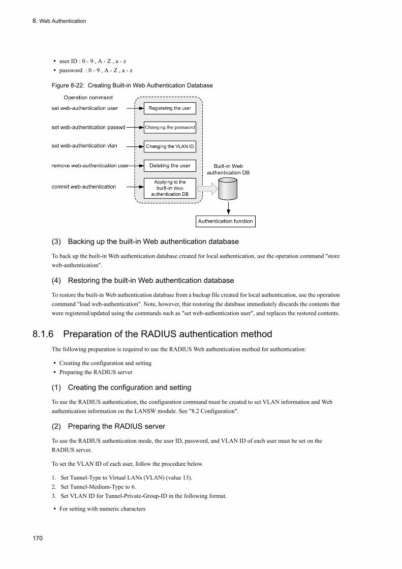
8. Web Authentication
• user ID : 0 - 9 , A - Z , a - z• password : 0 - 9 , A - Z , a - z
Figure 8-22: Creating Built-in Web Authentication Database
(3) Backing up the built-in Web authentication database
To back up the built-in Web authentication database created for local authentication, use the operation command "store web-authentication".
(4) Restoring the built-in Web authentication database
To restore the built-in Web authentication database from a backup file created for local authentication, use the operation command "load web-authentication". Note, however, that restoring the database immediately discards the contents that were registered/updated using the commands such as "set web-authentication user", and replaces the restored contents.
8.1.6 Preparation of the RADIUS authentication methodThe following preparation is required to use the RADIUS Web authentication method for authentication:
• Creating the configuration and setting• Preparing the RADIUS server
(1) Creating the configuration and setting
To use the RADIUS authentication, the configuration command must be created to set VLAN information and Web authentication information on the LANSW module. See "8.2 Configuration".
(2) Preparing the RADIUS server
To use the RADIUS authentication mode, the user ID, password, and VLAN ID of each user must be set on the RADIUS server.
To set the VLAN ID of each user, follow the procedure below.
1. Set Tunnel-Type to Virtual LANs (VLAN) (value 13).2. Set Tunnel-Medium-Type to 6.3. Set VLAN ID for Tunnel-Private-Group-ID in the following format.
• For setting with numeric characters
170

8. Web Authentication
Example: If VLAN ID is 2048, set 2048 as a character string.• For setting VLAN ID with numeric characters following the string "VLAN"
Example: If VLAN ID is 2048, set VLAN2048.
Each of the user ID and password consists of 1 to 32 characters. The following characters can be used:
• User ID: 0x21 to 0x7E of the ASCII character code• Password: 0x21 to 0x7E of the ASCII character code
PAP is set as the authentication method.
The table below lists the attributes of RADIUS used for the Web authentication. For details of the RADIUS server setting method, refer to the manual on the RADIUS server to be used.
Table 8-2: Attribute Names Used for Authentication(Part 1 Access-Request)
Table 8-3: Attribute Names Used for Authentication(Part 1 Access-Accept)
Attribute Names value of type
Description
User-Name 1 Specifies the user name.
User-Password 2 Specifies the user user password.
NAS-IP-Address 4 If the IP address of the loopback interface is specified, it is stored. If not, the IP address of the interface that communicates with the RADIUS server is stored.
Service-Type 6 Sets Framed(2).
Calling-Station-Id 31 Specifies the MAC address (lowercase ASCII, "-" delimiter) of the authentication terminal.Example : 00-12-e2-12-34-56
NAS-Identifier 32 Specifies VLAN ID accommodating the authentication terminal in the static VLAN mode, as a numeric character string.Example: 100 for VLAN ID 100In the dynamic VLAN mode and legacy mode, specifies the device name specified with configuration command "hostname."
NAS-Port-Type 61 Sets Virtual(5).
NAS-IPv6-Address 95 When the IPv6 address of the loopback interface is specified, it is stored. If not, the IPv6 address of the interface that communicates with the RADIUS server is stored. If, however, communication is performed using the IPv6 link local address, the IPv6 link local address of the transmission interface is stored, regardless of whether the IPv6 address of the loopback interface is set.
Attribute Names value of type
Description
Service-Type 6 Returns Framed(2). The Web authentication performs no check.
Reply-Message 18 (Unused)
Tunnel-Type 64 Used in the dynamic VLAN mode and legacy mode.Checks whether or not the value is 13 that indicates VLAN.Not used in the static VLAN mode.
Tunnel-Medium-Type 65 Used in the dynamic VLAN mode and legacy mode.Checks whether or not Tunnel-Medium-Type of value 6 as that is same as for EEE802.1X.Not used in the static VLAN mode.
171

8. Web Authentication
Table 8-4: Attribute Names Used for RADIUS Accounting
8.1.7 Authentication Error MessageShown below is the format of the authentication error messages that may be displayed on the authentication error screen.
Figure 8-23: Authentication Error Message Format
The following table provides causes of authentication errors:
Tunnel-Private-Group-Id 81 Used in the dynamic VLAN mode and legacy mode.Numeric character string indicating VLAN, or "VLANxx" (xx indicates VLAN ID.)However, since the content of the first octet 0x00 to 0x1f indicates Tag, the values of the second and subsequent octets indicate VLAN. If the content of the first octet is 0x20 and above, VLAN is indicated from the beginning.Not used in the static VLAN mode.
Attribute Names value of type
Description
User-Name 1 Stores the name of the user.
NAS-IP-Address 4 Stores the NAS IP address.If the IP address of the loopback interface is set, it is stored. In cases other than above, the IP address of the interface that communicates with the server is stored.
Service-Type 6 Sets Framed(2).
Calling-Station-Id 31 Sets the MAC address (lowercase ASCII, "-" delimiter) of the terminal.Example : 00-12-e2-12-34-56
NAS-Identifier 32 Sets the VLAN ID accommodating the authentication terminal in the static VLAN mode, as a numeric character string.For Example : 100 for VLAN ID 100In the dynamic VLAN mode and legacy mode, specifies the device name specified with configuration command "hostname."
Acct-Status-Type 40 Stores Start(1) at login and Stop(2) at logout.
Acct-Delay-Time 41 Stores the time (seconds) required from event generation to transmission.
Acct-Session-Id 44 Stores the process ID (same value is used for login and logout).
Acct-Authentic 45 Stores RADIUS or Local to indicate how the user was authenticated.
Acct-Session-Time 46 Stores the time (seconds) from the login to the logout.
NAS-Port-Type 61 Sets Virtual(5).
NAS-IPv6-Address 95 Stores the NAS IPv6 address.If the IPv6 address of the loopback interface is set, it is stored. In cases other than above, the IPv6 address of the interface that communicates with the server is stored. However, to perform communication using the IPv6 link local address, the IPv6 link local address of the transmission interface is stored, regardless of whether or not the IPv6 address of the loopback interface is set.
Attribute Names value of type
Description
172

8. Web Authentication
Table 8-5: Authentication Error Messages and Corresponding Causes
Content of Error Message Error Number
Cause of Error
User ID or password is wrong.Please enter correct user ID and password.
11 The login user ID is omitted.
12 The specified login user ID exceeds 32 characters.
13 The password is not specified. Alternatively, the specified number of characters is too long.
14 The specified login user ID is not registered in the built-in Web authentication database.
15 The specified password is not registered in the built-in Web authentication database.
16 "QUERY_STRING" of the GET method is shorter than 21 characters or exceeds 256 characters.
17 "CONTENT_LENGTH" of the POST method is shorter than 21 characters or exceeds 256 characters.
18 The specified login user ID contains a character not allowed.
20 The specified password contains a character not allowed.
22 Passwords did not match when a relogin was made from the authenticated terminal using the local authentication method .
RADIUS: Authentication reject. 31 Other than authentication permission (access rejection or access challenge) was received from the RADIUS server.
RADIUS: No authentication response. 32 Failed to receive authentication permission from the RADIUS server (i.e. reception timeout or RADIUS server not set).
173

8. Web Authentication
You cannot login by this machine. 33 Post-authentication VLAN set on RADIUS is not VLAN that is defined by the Web authentication.
34 When a relogin was made from the authenticated terminal using the RADIUS authentication method, information other than authentication permission (access rejection or access challenge) was received from the RADIUS server.
35 In the static VLAN mode, the authentication target port to which the terminal is connected is linked down.Alternatively, the port is not set in the static VLAN mode.
36 VLAN that accommodates the port set in the static VLAN mode is suspended.Alternatively, VLAN is not set for the interface.
41 Different users requested for login from the terminals with the same MAC address.
42 VLAN ID set in the built-in Web authentication database is not VLAN that is defined by the Web authentication.
44 In the same terminal, "IEEE802.1X or authenticated by MAC authentication" or "Mac-address configuration command in the terminal MAC address is registered in the MAC VLAN" is not registered for certification..
45 The authentication target port to which the terminal is connected is linked down. Alternatively, the port is not set in the static VLAN mode or dynamic VLAN mode.
46 VLAN that accommodates the port to be authenticated is suspended.Alternatively, VLAN is not set for the interface.
47 Authentication failed because the Web authentication login count exceeded the maximum accommodation condition.
76 When the MAC address is registered in the MAC address table, the port to which the terminal is connected is linked down. Alternatively, the port is not set in the static VLAN mode or dynamic VLAN mode.
77 When the MAC address is registered in the MAC address table, the VLAN to be accommodated is suspended. Alternatively, VLAN is not set for the interface.
Sorry, you cannot login just now.Please try again after a while.
43 Authentication failed because the login count of the Web, MAC, or IEEE802.1X authentication exceeded the maximum accommodation condition.
51 Failed to resolve the MAC address from the IP address of the login terminal.
52 The Web server failed to connect to the Web authentication daemon.
53 Web authentication internal error(The Web server failed to pass the login request to the Web authentication daemon.)
54 Web authentication internal error(The Web server failed to receive the response from the Web authentication daemon.)
Content of Error Message Error Number
Cause of Error
174

8. Web Authentication
Action for each error number• 1x to 2x: Log in again using the correct user ID and password.• 3x: Review the RADIUS setting.• 4x: Review the setting of built-in Web authentication database.• 5x: Using operation command "restart web-authentication", restart Web authentication.• 6x to 7x: Using operation command "restart web-authentication", restart Web authentication.• 8x: Another logout operation is needed.
8.1.8 Function of Changing Web Authentication ScreensThe operation command can be used to change "web authentication screens": that is, the information about the screens displayed on the web browser, such as the login and logout screens used for web authentication. If any of the following screen files exists in the directory specified by the operation command, it is replaced with the particular web authentication screen. It is also possible to simultaneously register "gif" and other image files, in addition to the following files. During registration, however, each file undergoes the size check alone and the content of the file is not checked. Therefore, be sure to check the operation before you register the HTML or image file.
The following is a list of screens that can be changed.
[Changeable screens]
• Login screen• Logout screen• Successful login screen• Unsuccessful login screen• Completed logout screen
The system error occurred.Please contact the system administrator.
61 Web authentication internal error(Failed to acquire "CONTENT_LENGTH" of the POST method.)
62 Web authentication internal error(Two or more "&"s were contained in the parameter received through POST/GET.)
63 Web authentication internal error(The Web server failed to acquire the terminal IP address.)
64 Access to RADIUS and Accounting failed (resulting in authentication failure)
A fatal error occurred.Please inform the system administrator.
71 Web authentication internal error(More than 256 authentication requests to RADIUS occurred at the same time.)
72 Registering the MAC address authenticated for MAC VLANfailed.
73 Deleting the MAC address de-authenticated from MAC VLANfailed.
74 An error occurred when the MAC address is registered in the MACaddress table.
75 An error occurred when the MAC address is deleted from the MACaddress table.
Sorry, you cannot logout just now.Please try again after a while.
81 Resulting the MAC address from the IP address for the logoutrequest terminal failed.
The client PC is not authenticated. 82 This is a logout request from a non-logout terminal
Content of Error Message Error Number
Cause of Error
175

8. Web Authentication
• Unsuccessful logout screen
The operation command can also be used to delete a registered web authentication screen. After the deletion process, you are returned to the default web authentication screen.
Note also that you can change the authentication error messages listed in Table 7-1, "Relationship Between Authentication Error Messages and Error Causes".
Additionally, you can change the icon (favicon.ico) displayed in the web browser's favorite.
For details about each file, see Section 7.4, "Guide to Creating Web Authentication Screens".
However, if one of the following interrupts occurs during Web authentication screen registration, the registered screen is not displayed and the default screen appears. In this case, if the Web authentication screen registration information is displayed with operation command "show web-authentication html-files"ÅCthe display may indicate as if the registration was successful.
• Processing was interrupted intentionally by pressing [Ctrl]+[C] during Web authentication screen registration.• A user was logged in the console via telnet, and telnet was interrupted due to a certain cause during Web
authentication screen registration.
If an interrupt occurs during Web authentication screen registration, register that screen again.
8.1.9 Coexistence with Other FunctionsThe following shows the coexistence relationship between the Web authentication and other functions:
(1) Coexistence with IEEE802.1X
The Web authentication can coexist with IEEE802.1X under the following conditions:
Table 8-6: Coexistence with IEEE802.1X
Note 1After the Web authentication is successful in the same terminal (having the same MAC address), if the IEEE802.1X port-level authentication or VLAN-level authentication (static) is successful, the IEEE802.1X authentication result is given priority and the Web authentication status is cancelled (in this case, the logout screen does not appear).
Authentication mode Authentication submode
Web authentication
Static VLAN mode*1 Dynamic VLAN mode
Legacy mode
Port-level authentication Single mode Do not make the setting for the same port.
Exclusion for each port
Exclusion for each port
Single mode Do not make the setting for the same port.
Exclusion for each port
Exclusion for each port
Terminal authentication mode
Coexistence for each port
Exclusion for each port
Exclusion for each port
VLAN-level authentication (static)
Terminal authentication mode
Coexistence for each port set for the VLAN-level authentication (static)
Exclusion for each VLAN
Exclusion for each VLAN
VLAN-level authentication (dynamic)*2
Terminal authentication mode
Exclusion for each VLAN
Coexistence is possible for the same port.*3
Coexistence is possible for the same port.*4
176

8. Web Authentication
The figure below shows the following: the terminal connected via HUB (HUB#1 in the figure) connected to a different port changes its connection to another HUB (HUB#2 in the figure) after it is authenticated with the IEEE802.1X (port-level authentication (terminal authentication mode) or VLAN-level authentication (static)). In this case, unless the IEEE802.1X authentication is cancelled, the Web authentication (static VLAN mode) login cannot be performed. Cancel the authentication with IEEE802.1X operation command "clear dot1x auth-state."
Figure 8-24: Use of the Web Authentication After Movement of the Port of the Terminal Authenticated with IEEE802.1X
Note 2As shown in the figure below, the coexistence is possible with the same port.
Figure 8-25: Coexistence with the IEEE802.1X (VLAN-level authentication (dynamic))
Note 3After the Web authentication (dynamic VLAN mode) is successful in the same terminal (having the same MAC address), if the IEEE802.1X VLAN-level authentication (dynamic) is successful, the IEEE802.1X authentication result is given priority, the relevant VLAN is switched to the VLAN set with IEEE802.1X, and the Web authentication status is cancelled (in this case, the logout screen is not displayed).
Note 4After the Web authentication (Legacy mode) is successful in the same terminal (having the same MAC address), if the IEEE802.1X VLAN-level authentication (dynamic) is successful, the IEEE802.1X authentication result is given priority, and the relevant VLAN is switched to the VLAN set with IEEE802.1X and the Web authentication status is cancelled (in this case, the logout screen is not displayed).
177

8. Web Authentication
(2) Coexistence with the MAC Authentication
The Web authentication can coexist with the MAC authentication under the following conditions:
Table 8-7: Coexistence with the MAC Authentication
If the MAC authentication is successful earlier in the same terminal (having the same MAC address), the Web authentication results in an error. On the other hand, if the Web authentication is successful earlier, the Web authentication status remains unchanged (MAC authentication results in an error).
(3) Coexistence with OAN
The Web authentication can coexist with OAN. However, if the static VLAN mode and dynamic VLAN mode are valid, the following conditions are provided:
• If AX-Config-Master is connected to the authentication target port of this device and this device uses that port without the Web authentication, it is necessary to specify the https port (832, 9698) to be used with OAN, using configuration command "web-authentication web-port."
• If AX-Config-Master is connected to the authentication target port and the device connected to the outside of this device is managed without the Web authentication, the IP packet used with OAN needs to be transmitted and received, using the access list as shown in the figure below.
Figure 8-26: Coexistence with OAN
(4) Functions excluded from the coexistence
The following functions are excluded from the coexistence:
• Authentication VLAN• IGMP snooping in the static VLAN mode
Authentication mode Authentication submode Web authentication
Static VLAN mode Dynamic VLAN mode
Static VLAN Mode Coexistence for each port Exclusion for each system Exclusion for each system
Dynamic VLAN Mode Exclusion for each system Coexistence for each port Exclusion for each system
178
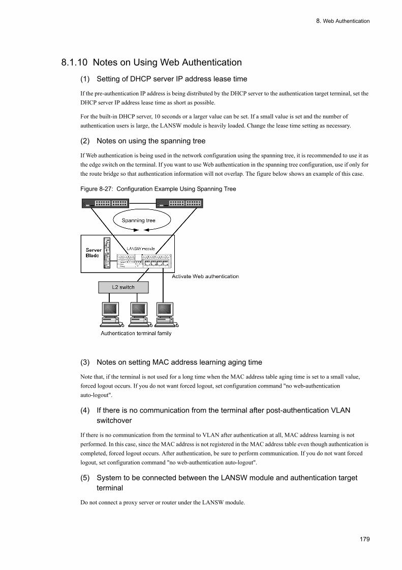
8. Web Authentication
8.1.10 Notes on Using Web Authentication
(1) Setting of DHCP server IP address lease time
If the pre-authentication IP address is being distributed by the DHCP server to the authentication target terminal, set the DHCP server IP address lease time as short as possible.
For the built-in DHCP server, 10 seconds or a larger value can be set. If a small value is set and the number of authentication users is large, the LANSW module is heavily loaded. Change the lease time setting as necessary.
(2) Notes on using the spanning tree
If Web authentication is being used in the network configuration using the spanning tree, it is recommended to use it as the edge switch on the terminal. If you want to use Web authentication in the spanning tree configuration, use if only for the route bridge so that authentication information will not overlap. The figure below shows an example of this case.
Figure 8-27: Configuration Example Using Spanning Tree
(3) Notes on setting MAC address learning aging time
Note that, if the terminal is not used for a long time when the MAC address table aging time is set to a small value, forced logout occurs. If you do not want forced logout, set configuration command "no web-authentication auto-logout".
(4) If there is no communication from the terminal after post-authentication VLAN switchover
If there is no communication from the terminal to VLAN after authentication at all, MAC address learning is not performed. In this case, since the MAC address is not registered in the MAC address table even though authentication is completed, forced logout occurs. After authentication, be sure to perform communication. If you do not want forced logout, set configuration command "no web-authentication auto-logout".
(5) System to be connected between the LANSW module and authentication target terminal
Do not connect a proxy server or router under the LANSW module.
179

8. Web Authentication
If a system (proxy server or router) that rewrites the MAC address of the client terminal exists on the route between the LANSW module and the terminal to be authenticated, authentication for each terminal cannot be performed because Web authentication recognizes the rewritten MAC address as the terminal to be authenticated.
Note that, if a HUB or wireless LAN having no inter-port shutoff function is connected under the LANSW module and it has multiple PCs connected, PCs can communicate with each other even though authentication is not completed.
Figure 8-28: Connection between the LANSW module and Terminal
(6) Terminal IP address after logout
After logout (logout using the Web screen, forced logout after the maximum connection time is expired, or forced logout due to "mac-address-table" aging timeout), change the terminal IP address to the pre-authentication IP address.
• For manual setting, change the terminal IP address manually to the pre-authentication IP address.• When using the DHCP server, delete the terminal IP address before instructing the DHCP server to distribute the IP
address (for example, when operating Windows, first execute "ipconfig /release" from the command prompt, and then execute "ipconfig /renew").
(7) Setting the maximum connection time
If the maximum connection time is shortened or extended using configuration command "web-authentication max-timer", this setting is not applied to the user who is currently being authenticated but it is enabled after the next login.
(8) When changing the built-in Web authentication database
If addition/change to the built-in Web authentication database is performed using the operation command, this setting is not applied to the user who is currently being authenticated but it is enabled after the next login.
180

8. Web Authentication
(9) If Web authentication program restarts
When the Web authentication daemon restarts, authentication status of all authenticated users is reset. In this case, re-authenticate manually from the terminal after the restart.
(10) Notes on extending the authentication connection time
When logging in again while authenticated, you can extend the authentication time if the combination of specified login ID and MAC address matches. The password still needs to be specified, but the specified password is not checked. Even if the user ID is deleted from the built-in Web authentication database (in local authentication mode) or RADIUS (in RADIUS authentication mode), the authentication time is extended because the user ID is not checked.
(11) Note on specifying the host name for RADIUS server setting
When the RADIUS server used in Web authentication is specified by its host name using configuration command "redius-server host", the following phenomena may occur in the environment where name resolution is disabled for some reason (e.g. connection to the DNS server is disabled):
• When an operation command is executed• The display speed of the execution result slows down.• The display is interrupted temporaliry and then it resumes.• "Can't execute." is displayed.
• When a Web authentication configuration command is executed• It may take time to save the configuration or to apply the configuration to the operation.
To avoid the phenomena above, it is recommended to use the IPv4 address for RADIUS server setting in Web authentication. If it is required to set the server by its host name, ensure that the DNS server can reply.
(12) When Web Authentication and IEEE 802.1X VLAN authentication (dynamic) are used on the same terminal
When both IEEE 802.1X VLAN authentication (dynamic) and Web authentication are used on the same terminal (terminal having the same MAC address), if the login operation is executed for the Web authentication after IEEE 802.1X authentication completes successfully, the Web screen displays that authentication is successful. However, the IEEE 802.1X authentication result takes precedence, and the Web authentication result is recorded as a failure. Therefore, only one of these authentication methods must be used on the same terminal.
If IEEE 802.1X VLAN authentication (dynamic) is successful after Web authentication is successful on the terminal, the IEEE 802.1X authentication result takes precedence and switching to VLAN set in IEEE 802.1X occurs. In this case, the status of Web authentication remains for a while, and then the status is cancelled.
(13) If switching to the post-authentication VLAN fails
The Web screen displays that authentication is successful even though switching to the post-authentication VLAN fails. However, authentication failure is recorded in the authentication information of Web authentication.
(14) Interface IP address that can be set for Web authentication
For Web authentication, be sure to set an IP address on the interface for which the pre-authentication and post-authentication VLANs are set. The supported IP address is only IPv4 address. If an IPv6 address is set, authentication fails.
(15) Note on using the set clock command
Since the authentication connection time is based on the LANSW module clock, changing the date and time by the
181

8. Web Authentication
operation command set clock affects the authentication connection time. For example, when the clock is advanced by three hours, three hours are added to the elapsed connection time. On the contrary, when the clock is set back by three hours, the authentication time extends by three hours.
(16) Note on disconnection with the RADIUS server
If the communication with the RADIUS server used for the Web authentication is disconnected, or if the RADIUS server specified by the configuration command "radius-server host" does not exist, each login request consumes the timeout period specified by the configuration command "radius-server timeout" and then retries transmission for the number of times specified by the configuration command "radius-server retransmit". As a result, the authentication for each login request takes more time.
When more than one RADIUS server is set, those RADIUS servers are accessed in the order of settings in "radius-server host" command every time login is executed. Therefore, if communication is disabled due to a failure in one of the RADIUS servers, the authentication process takes time at the subsequent servers.
In this case, stop the login operation for the Web authentication, and set the RADIUS server without a failure with the "radius-server host" command before resuming the login operation.
(17) Operation when the VLAN function is restarted
When the VLAN function is restarted by the operation command "restart vlan", the Web authentication does not reset the authentication status and registers the authenticated terminals to MAC VLAN in the order that the terminals are authenticated. However, it takes time to register to MAC VLAN if there are many authenticated terminals and the communication to the post-authentication VLAN is disabled until registration completes.
(18) Note when MAC VLAN configuration command mac-based-vlan static-only command is set
When configuration command mac-based-vlan static-only of MAC VLAN is set, the Web attestation cannot be set.
(19) Note when Web attestation screen registration processing interrupts
The default screen is displayed without displaying the registered screen when the interruption shown as follows while registering the Web attestation screen occurs. In this case, it might be displayed that the registered information of the Web attestation screen is displayed by the operation command as if registration succeeded.
• When you intentionally interrupt processing pushing "Ctrl + C" while registering the Web attestation screen. • When the console is logged in by way of the telnet, and the telnet is cut by some factors while registering the Web
attestation screen.
Please register the Web attestation screen again when the interruption occurs while registering the Web attestation screen.
(20) Interface IP address That Can Be Set for the Web Authentication
In the static VLAN mode, be sure to specify the IP address for the VLAN interface to be subjected to the Web authentication. Moreover, in the dynamic VLAN mode and legacy mode, be sure to specify the IP address for the interface for which the pre-authentication VLAN and post-authentication VLAN are set.
However, the IP address that can be set is only the IPv4 address. If only the IPv6 address is specified, the interface cannot be authenticated. In setting the RADIUS server, either of the IPv6 and IPv4 addresses can be specified.
(21) Setting the IEEE802.1X Configuration in the Static VLAN Mode
Do not set the IEEE802.1X configuration command shown below, for the port set as the authentication port in the static
182
8. Web Authentication
VLAN mode.
Moreover, do not set the single mode and multi-mode of the IEEE802.1X port-level authentication, for the authentication port.
• dot1x force-authorized-port• dot1x port-control force-authorized• dot1x port-control force-unauthorized• dot1x multiple-hosts
(22) Note on Setting the Proxy Server for the Terminal
If the URL redirect function is valid and the proxy server is set for the Web browser of the terminal, be sure to make the setting so that the Web authentication-dedicated IP address is not used from the proxy server.
(23) Notices on Using the URL Redirect Function
When the URL is accessed via https from the pre-authentication terminal using the URL redirect function, if the URL does not match the domain name of the certificate registered in the device, the warning message indicating certificate inconsistency appears on the Web browser. If operation is continued although the warning message appears, the Web authentication login screen appears to enable the login.
183

8. Web Authentication
8.2 Configuration
8.2.1 List of Configuration CommandsThe list of configuration commands for Web authentication is shown in the table below.
Table 8-8: List of Configuration Commands
Command Description
aaa accounting web-authentication default start-stop group radius
Sets the use of the accounting server.
aaa authentication web-authentication default group radius
Sets the use of the RADIUS server.
authentication arp-relay Specified when the ARP packet from the pre-authentication terminal is to betransferred to the outside of this device.
authentication ip access-group When the packet from the pre-authentication terminal is transferred to theoutside of this device, specifies the type of that packet in the IPv4 access list.
web-authentication auto-logout Sets the forced logout function by MAC address learning aging timeout.
web-authentication ip address Specifies the Web authentication-dedicated IP address in the static VLANmode and dynamic VLAN mode.
web-authentication jump-url Specifies the URL to be accessed from the terminal after the authentication issuccessful.
web-authentication logging enable Starts the output of the authentication results and operation log to the syslogserver.
web-authentication logout ping tos-windows Specifies the TOS value of special ping sent from the authenticated terminal.
web-authentication logout ping ttl Specifies the TTL value of special ping sent from the authenticated terminal.
web-authentication logout polling count If no response is made for the monitoring packet, specifies the number of timesthat the monitoring packet is re-sent.
web-authentication logout polling enable Enables the connection monitoring function that monitors the operation of theauthenticated terminal.
web-authentication logout polling interval Specifies the sending time of the monitoring packet (ARP) used with theconnection monitoring function.
web-authentication logout polling retry-interval Specifies the time interval of the monitoring packet to be re-sent when noresponse is made for that packet.
web-authentication max-timer Specifies the maximum connection time for Web authentication.
web-authentication max-user Specifies the maximum number of Web authentications that can be valid in the dynamic VLAN mode and legacy mode.
web-authentication port Specifies the port that is authenticated in the static VLAN mode and dynamicVLAN mode.
web-authentication redirect enable Validates the URL redirect function.
web-authentication redirect-mode During URL redirection, specifies the protocol (http or https) for the loginoperation displayed in the terminal.
web-authentication static-vlan max-user Specifies the number of users that can be authenticated in the static VLANmode.
web-authentication system-auth-control Enables Web authentication.
web-authentication vlan In the legacy mode, specifies the switched VLAN that is allowed to be switched in the Web authentication.
web-authentication web-port Specified when the access port number of the Web server is to be added.
184

8. Web Authentication
8.2.2 Configuration in the Static VLAN Mode
(1) Basic Setting of the Local Authentication Method
The following figure shows the basic setting used when the local authentication method is used:
Figure 8-29: Basic Configuration of the Local Authentication Method in the Static VLAN Mode
(a) Setting the Authentication Port
[Point of setting]Set the port used for the Web authentication.
[Setup using commands]
1. (config)# vlan 10
(config-vlan)# state active
(config-vlan)# exit
2. (config)# interface gigabitethernet 0/4
(config-if)# switchport mode access
(config-if)# switchport access vlan 10
(config-if)# web-authentication port
(config-if)# exit
Set the VLAN ID and Web authentication for the port to which the terminal to be authenticated is connected.
3. (config)# interface gigabitethernet 0/11
(config-if)# switchport mode access
(config-if)# switchport access vlan 10
(config-if)# exit
Specify the port to which the L3 switch of the network to be accessed after authentication is connected.
185

8. Web Authentication
(b) Setting the IP Address for the VLAN Interface
[Point of setting]Specify the IP address for VLAN used for the Web authentication.
[Setup using commands]
1. (config)# interface vlan 10
(config-if)# ip address 192.168.10.254 255.255.255.0
(config-if)# exit
Specify the IP address for VLAN ID 10 used for the Web authentication.
(c) Setting the Authentication-Dedicated IPv4 Access List
[Point of setting]Set the authentication-dedicated IPv4 access list that allows the communication from the pre-authentication terminal to the outside of this device.
[Setup using commands]
1. (config)# ip access-list extended 100
(config-ext-nacl)# permit udp any any eq bootps
(config-ext-nacl)# permit ip any host 10.0.0.1
(config-ext-nacl)# exit
(config)# interface gigabitethernet 0/4
(config-if)# authentication ip access-group 100
(config-if)# authentication arp-relay
(config-if)# exit
Set the authentication-dedicated IPv4 access list that allows access to the DHCP packet and IP address 10.0.0.1 (DNS server) from the pre-authentication terminal. Moreover, make the setting so that the ARP packet is transferred to the outside of this device.
(d) Setting the Web Authentication
[Point of setting]Set the Web authentication configuration command to enable the Web authentication.
[Setup using commands]
1. (config)# web-authentication ip address 10.10.10.1
Specify the Web authentication-dedicated IP address (IPv4 address).
2. (config)# web-authentication system-auth-control
2.Start the Web authentication.
(2) Basic Setting of the RADIUS Authentication Method
The following figure shows the basic setting for use of the RADIUS authentication method:
186

8. Web Authentication
Figure 8-30: Basic Configuration of the RADIUS Authentication Method in the Static VLAN Mode
(a) Set the port used for the Web authentication.
[Point of setting]Set the port used for the Web authentication.
[Setup using commands]
1. (config)# vlan 10
(config-vlan)# state active
(config-vlan)# exit
2. (config)# interface gigabitethernet 0/4
(config-if)# switchport mode access
(config-if)# switchport access vlan 10
(config-if)# web-authentication port
(config-if)# exit
Set the VLAN ID and Web authentication for the port to which the terminal to be authenticated is connected.
3. (config)# interface gigabitethernet 0/11
(config-if)# switchport mode access
(config-if)# switchport access vlan 10
(config-if)# exit
Specify the port to which the L3 switch of the network to be accessed after authentication is connected.
(b) Setting the IP Address for the VLAN Interface
[Point of setting]Specify the IP address for VLAN used for the Web authentication.
187

8. Web Authentication
[Setup using commands]
1. (config)# interface vlan 10
(config-if)# ip address 192.168.10.254 255.255.255.0
(config-if)# exit
Specify the IP address for VLAN ID 10 used for the Web authentication.
(c) Setting the Authentication-Dedicated IPv4 Access List
[Point of setting]Set the authentication-dedicated IPv4 access list that allows the communication from the pre-authentication terminal to the outside of this device.
[Setup using commands]
1. (config)# ip access-list extended 100
(config-ext-nacl)# permit udp any any eq bootps
(config-ext-nacl)# permit ip any host 10.0.0.1
(config-ext-nacl)# exit
(config)# interface gigabitethernet 0/4
(config-if)# authentication ip access-group 100
(config-if)# authentication arp-relay
(config-if)# exit
Set the authentication-dedicated IPv4 access list that allows access to the DHCP packet and IP address 10.0.0.1 (DNS server) from the pre-authentication terminal. Moreover, make the setting so that the ARP packet is transferred to the outside of this device.
(d) Setting the Web Authentication
[Point of setting]Set the Web authentication configuration command to enable the Web authentication.
[Setup using commands]
1. (config)# web-authentication ip address 10.10.10.1
Specify the Web authentication-dedicated IP address (IPv4 address).
2. (config)# aaa authentication web-authentication default group radius
(config)# radius-server host 10.0.0.200 key "webauth"
Set the IP address and RADIUS key used to perform the user authentication in the RADIUS server.
3. (config)# web-authentication system-auth-control
Start the Web authentication.
(3) Setting Made When the RADIUS Authentication Method and Built-in DHCP Server Are Used
The following figure shows the basic configuration used when the RADIUS authentication method and the DHCP server within this device are used:
188

8. Web Authentication
Figure 8-31: Basic Configuration of the RADIUS Authentication Method in the Static VLAN Mode and the Built-in DHCP Server
(a) Setting the Authentication Port
[Point of setting]Set the port used for the Web authentication.
[Setup using commands]
1. (config)# interface gigabitethernet 0/4
(config-if)# switchport mode access
(config-if)# switchport access vlan 10
(config-if)# web-authentication port
(config-if)# exit
Set the VLAN ID and Web authentication for the port to which the terminal to be authenticated is connected.
2. (config)# interface gigabitethernet 0/11
(config-if)# switchport mode access
(config-if)# switchport access vlan 10
(config-if)# exit
Specify the port to which the L3 switch of the network to be accessed after authentication is connected.
(b) Setting the IP Address for the VLAN Interface
[Point of setting]Specify the IP address for VLAN used for the Web authentication.
[Setup using commands]
189
8. Web Authentication
1. (config)# interface vlan 10
(config-if)# ip address 192.168.10.254 255.255.255.0
(config-if)# exit
1.Specify the IP address for VLAN ID 10 used for the Web authentication.
(c) Setting the Authentication-Dedicated IPv4 Access List
[Point of setting]Set the authentication-dedicated IPv4 access list that allows the communication from the pre-authentication terminal to the outside of this device.
[Setup using commands]
1. (config)# ip access-list extended 100
(config-ext-nacl)# permit udp host 0.0.0.0 host 192.168.10.254 eq bootps
(config-ext-nacl)# permit udp host 0.0.0.0 host 255.255.255.255 eq bootps
(config-ext-nacl)# permit ip any host 10.0.0.1
(config-ext-nacl)# exit
(config)# interface gigabitethernet 0/4
(config-if)# authentication ip access-group 100
(config-if)# authentication arp-relay
(config-if)# exit
Set the authentication-dedicated IPv4 access list that allows access to the DHCP packets for this equipment DHCP server and IP address 10.0.0.1 (DNS server) from the pre-authentication terminal. Moreover, make the setting so that the ARP packet is transferred to the outside of this device.
(d) Setting the Web Authentication
[Point of setting]Set the Web authentication configuration command to enable the Web authentication.
[Setup using commands]
1. (config)# web-authentication ip address 10.10.10.1
Specify the Web authentication-dedicated IP address (IPv4 address).
2. (config)# aaa authentication web-authentication default group radius
(config)# radius-server host 10.0.0.200 key "webauth"
Set the IP address and RADIUS key used to perform the user authentication in the RADIUS server.
3. (config)# web-authentication system-auth-control
Start the Web authentication.
8.2.3 Configuration in the Dynamic VLAN Mode
(1) Basic Setting in the Local Authentication Method
The figure below shows the basic setting used when the local authentication method is used. The IP address of the terminal is distributed from the DHCP server within this device before authentication and is distributed from an external DHCP server after authentication.
190

8. Web Authentication
Moreover, The filter is set which disables the communication between the pre-authentication VLAN and post-authentication VLAN.
Figure 8-32: Basic Configuration of the Local Authentication Method in the Dynamic VLAN Mode
(a) Setting the Authentication Port
[Point of setting]Set the port used for the Web authentication.
[Setup using commands]
1. (config)# interface gigabitethernet 0/4
(config-if)# switchport mode mac-vlan
(config-if)# switchport mac vlan 50
(config-if)# switchport mac native vlan 10
(config-if)# web-authentication port
(config-if)# exit
Set the MAC VLAN and Web authentication for the port to which the terminal to be authenticated is connected.
2. (config)# interface range gigabitethernet 0/9-10
(config-if-range)# switchport mode access
(config-if-range)# switchport access vlan 50
(config-if-range)# exit
Specify the port of the network to be accessed after authentication.
191
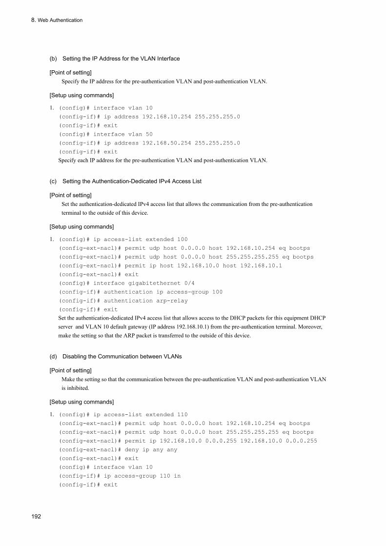
8. Web Authentication
(b) Setting the IP Address for the VLAN Interface
[Point of setting]Specify the IP address for the pre-authentication VLAN and post-authentication VLAN.
[Setup using commands]
1. (config)# interface vlan 10
(config-if)# ip address 192.168.10.254 255.255.255.0
(config-if)# exit
(config)# interface vlan 50
(config-if)# ip address 192.168.50.254 255.255.255.0
(config-if)# exit
Specify each IP address for the pre-authentication VLAN and post-authentication VLAN.
(c) Setting the Authentication-Dedicated IPv4 Access List
[Point of setting]Set the authentication-dedicated IPv4 access list that allows the communication from the pre-authentication terminal to the outside of this device.
[Setup using commands]
1. (config)# ip access-list extended 100
(config-ext-nacl)# permit udp host 0.0.0.0 host 192.168.10.254 eq bootps
(config-ext-nacl)# permit udp host 0.0.0.0 host 255.255.255.255 eq bootps
(config-ext-nacl)# permit ip host 192.168.10.0 host 192.168.10.1
(config-ext-nacl)# exit
(config)# interface gigabitethernet 0/4
(config-if)# authentication ip access-group 100
(config-if)# authentication arp-relay
(config-if)# exit
Set the authentication-dedicated IPv4 access list that allows access to the DHCP packets for this equipment DHCP server and VLAN 10 default gateway (IP address 192.168.10.1) from the pre-authentication terminal. Moreover, make the setting so that the ARP packet is transferred to the outside of this device.
(d) Disabling the Communication between VLANs
[Point of setting]Make the setting so that the communication between the pre-authentication VLAN and post-authentication VLAN is inhibited.
[Setup using commands]
1. (config)# ip access-list extended 110
(config-ext-nacl)# permit udp host 0.0.0.0 host 192.168.10.254 eq bootps
(config-ext-nacl)# permit udp host 0.0.0.0 host 255.255.255.255 eq bootps
(config-ext-nacl)# permit ip 192.168.10.0 0.0.0.255 192.168.10.0 0.0.0.255
(config-ext-nacl)# deny ip any any
(config-ext-nacl)# exit
(config)# interface vlan 10
(config-if)# ip access-group 110 in
(config-if)# exit
192

8. Web Authentication
2. (config)# ip access-list extended 150
(config-ext-nacl)# permit udp host 0.0.0.0 host 192.168.50.100 eq bootps
(config-ext-nacl)# permit udp host 0.0.0.0 host 255.255.255.255 eq bootps
(config-ext-nacl)# permit udp host 192.168.50.100 any eq bootpc
(config-ext-nacl)# permit ip 192.168.50.0 0.0.0.255 192.168.50.0 0.0.0.255
(config-ext-nacl)# deny ip any any
(config-ext-nacl)# exit
(config)# interface vlan 50
(config-if)# ip access-group 150 in
(config-if)# exit
Make the setting so that the communication is not established between the pre-authentication VLAN and post-authentication VLAN.
(e) Setting the Web Authentication
[Point of setting]Set the Web authentication configuration command to enable the Web authentication.
[Setup using commands]
1. (config)# web-authentication ip address 10.10.10.1
Specify the Web authentication-dedicated IP address (IPv4 address).
2. (config)# web-authentication system-auth-control
Start the Web authentication.
(2) Basic Setting of the RADIUS Authentication Method
The following figure shows the basic configuration used when the RADIUS authentication method and the DHCP server within this device are used. The IP address of the terminal is distributed from the DHCP server within this device before authentication and is distributed from an external DHCP server after authentication.
Moreover, The filter is set which disables the communication between the pre-authentication VLAN and post-authentication VLAN.
193

8. Web Authentication
Figure 8-33: Basic Configuration of the RADIUS Authentication Method in the Dynamic VLAN Mode
(a) Setting the Authentication Port
[Point of setting]Set the port used for the Web authentication.
[Setup using commands]
1. (config)# interface gigabitethernet 0/4
(config-if)# switchport mode mac-vlan
(config-if)# switchport mac vlan 50
(config-if)# switchport mac native vlan 10
(config-if)# web-authentication port
(config-if)# exit
Set the MAC VLAN and Web authentication for the port to which the terminal to be authenticated is connected.
2. (config)# interface range gigabitethernet 0/9-10
(config-if-range)# switchport mode access
(config-if-range)# switchport access vlan 50
(config-if-range)# exit
Specify the port of the network to be accessed after authentication.
(b) Setting the IP Address for the VLAN Interface
[Point of setting]Specify the IP address for the pre-authentication VLAN and post-authentication VLAN.
194

8. Web Authentication
[Setup using commands]
1. (config)# interface vlan 10
(config-if)# ip address 192.168.10.254 255.255.255.0
(config-if)# exit
(config)# interface vlan 50
(config-if)# ip address 192.168.50.254 255.255.255.0
(config-if)# exit
Specify each IP address for the pre-authentication VLAN and post-authentication VLAN.
(c) Setting the Authentication-Dedicated IPv4 Access List
[Point of setting]Set the authentication-dedicated IPv4 access list that allows the communication from the pre-authentication terminal to the outside of this device.
[Setup using commands]
1. (config)# ip access-list extended 100
(config-ext-nacl)# permit udp host 0.0.0.0 host 192.168.10.254 eq bootps
(config-ext-nacl)# permit udp host 0.0.0.0 host 255.255.255.255 eq bootps
(config-ext-nacl)# permit ip host 192.168.10.0 host 192.168.10.1
(config-ext-nacl)# exit
(config)# interface gigabitethernet 0/4
(config-if)# authentication ip access-group 100
(config-if)# authentication arp-relay
(config-if)# exit
Set the authentication-dedicated IPv4 access list that allows access to the DHCP packets for this equipment DHCP server and VLAN 10 default gateway (IP address 192.168.10.1) from the pre-authentication terminal. Moreover, make the setting so that the ARP packet is transferred to the outside of this device.
(d) Disabling the Communication between VLANs
[Point of setting]Make the setting so that the communication between the pre-authentication VLAN and post-authentication VLAN is inhibited.
[Setup using commands]
1. (config)# ip access-list extended 110
(config-ext-nacl)# permit udp host 0.0.0.0 host 192.168.10.254 eq bootps
(config-ext-nacl)# permit udp host 0.0.0.0 host 255.255.255.255 eq bootps
(config-ext-nacl)# permit ip 192.168.10.0 0.0.0.255 192.168.10.0 0.0.0.255
(config-ext-nacl)# deny ip any any
(config-ext-nacl)# exit
(config)# interface vlan 10
(config-if)# ip access-group 110 in
(config-if)# exit
2. (config)# ip access-list extended 150
(config-ext-nacl)# permit udp host 0.0.0.0 host 192.168.50.100 eq bootps
(config-ext-nacl)# permit udp host 0.0.0.0 host 255.255.255.255 eq bootps
(config-ext-nacl)# permit udp host 192.168.50.100 any eq bootpc
195

8. Web Authentication
(config-ext-nacl)# permit ip 192.168.50.0 0.0.0.255 192.168.50.0 0.0.0.255
(config-ext-nacl)# deny ip any any
(config-ext-nacl)# exit
(config)# interface vlan 50
(config-if)# ip access-group 150 in
(config-if)# exit
Make the setting so that the communication is not established between the pre-authentication VLAN and post-authentication VLAN.
(e) Setting the Web Authentication
[Point of setting]Set the Web authentication configuration command to enable the Web authentication.
[Setup using commands]
1. (config)# web-authentication ip address 10.10.10.1
Specify the Web authentication-dedicated IP address (IPv4 address).
2. (config)# aaa authentication web-authentication default group radius
(config)# radius-server host 192.168.10.200 key "webauth"
Set the IP address and RADIUS key used to perform the user authentication in the RADIUS server.
3. (config)# web-authentication system-auth-control
Start the Web authentication.
(3) Setting Made When the RADIUS Authentication Method Is Used and When the External DHCP Server Is Used Before Authentication
The figure below shows the configuration in which each IP address of the terminal is distributed from the corresponding external DHCP server before and after the authentication using the RADIUS authentication method.
The filter is set which inhibits the communication between the pre-authentication VLAN and the post-authentication VLAN.
196

8. Web Authentication
Figure 8-34: Configuration in Which the RADIUS Authentication Method in the Dynamic VLAN Mode and the External DHCP Server Are Used
(a) Setting the Authentication Port
[Point of setting]Set the port used for the Web authentication.
[Setup using commands]
1. (config)# interface gigabitethernet 0/4
(config-if)# switchport mode mac-vlan
(config-if)# switchport mac vlan 50
(config-if)# switchport mac native vlan 10
(config-if)# web-authentication port
(config-if)# exit
Set the MAC VLAN and Web authentication for the port to which the terminal to be authenticated is connected.
2. (config)# interface range gigabitethernet 0/9-10
(config-if-range)# switchport mode access
(config-if-range)# switchport access vlan 50
(config-if-range)# exit
Specify the port of the network to be accessed after authentication.
(b) Setting the IP Address for the VLAN Interface
[Point of setting]Specify the IP address for the pre-authentication VLAN and post-authentication VLAN.
197

8. Web Authentication
[Setup using commands]
1. (config)# interface vlan 10
(config-if)# ip address 192.168.10.254 255.255.255.0
(config-if)# exit
(config)# interface vlan 50
(config-if)# ip address 192.168.50.254 255.255.255.0
(config-if)# exit
Specify the IP address for the pre-authentication VLAN and post-authentication VLAN.
(c) Setting the Authentication-Dedicated IPv4 Access List
[Point of setting]Set the authentication-dedicated IPv4 access list that allows the communication from the pre-authentication terminal to the outside of this device.
[Setup using commands]
1. (config)# ip access-list extended 100
(config-ext-nacl)# permit udp host 0.0.0.0 host 192.168.10.100 eq bootps
(config-ext-nacl)# permit udp host 0.0.0.0 host 255.255.255.255 eq bootps
(config-ext-nacl)# permit ip host 192.168.10.0 host 192.168.10.1
(config-ext-nacl)# exit
(config)# interface gigabitethernet 0/4
(config-if)# authentication ip access-group 100
(config-if)# authentication arp-relay
(config-if)# exit
Set the authentication-dedicated IPv4 access list that allows access to the DHCP packets for this equipment DHCP server and VLAN 10 default gateway (IP address 192.168.10.1) from the pre-authentication terminal. Moreover, make the setting so that the ARP packet is transferred to the outside of this device.
(d) Disabling the Communication between VLANs
[Point of setting]Make the setting so that the communication between the pre-authentication VLAN and post-authentication VLAN is inhibited.
[Setup using commands]
1. (config)# ip access-list extended 110
(config-ext-nacl)# permit udp host 0.0.0.0 host 192.168.10.254 eq bootps
(config-ext-nacl)# permit udp host 0.0.0.0 host 255.255.255.255 eq bootps
(config-ext-nacl)# permit udp host 192.168.10.100 any eq bootpc
(config-ext-nacl)# permit ip 192.168.10.0 0.0.0.255 192.168.10.0 0.0.0.255
(config-ext-nacl)# deny ip any any
(config-ext-nacl)# exit
(config)# interface vlan 10
(config-if)# ip access-group 110 in
(config-if)# exit
2. (config)# ip access-list extended 150
(config-ext-nacl)# permit udp host 0.0.0.0 host 192.168.50.100 eq bootps
(config-ext-nacl)# permit udp host 0.0.0.0 host 255.255.255.255 eq bootps
198

8. Web Authentication
(config-ext-nacl)# permit udp host 192.168.50.100 any eq bootpc
(config-ext-nacl)# permit ip 192.168.50.0 0.0.0.255 192.168.50.0 0.0.0.255
(config-ext-nacl)# deny ip any any
(config-ext-nacl)# exit
(config)# interface vlan 50
(config-if)# ip access-group 150 in
(config-if)# exit
Make the setting so that the communication is not established between the pre-authentication VLAN and post-authentication VLAN.
(e) Setting the Web Authentication
[Point of setting]Set the Web authentication configuration command to enable the Web authentication.
[Setup using commands]
1. (config)# web-authentication ip address 10.10.10.1
Specify the Web authentication-dedicated IP address (IPv4 address).
2. (config)# aaa authentication web-authentication default group radius
(config)# radius-server host 192.168.10.200 key "webauth"
Set the IP address and RADIUS key used to perform the user authentication in the RADIUS server.
3. (config)# web-authentication system-auth-control
2.Start the Web authentication.
8.2.4 Configuration in the Legacy Mode
(1) Basic Configuration of Local Authentication Mode
The basic configuration for using the local authentication mode is shown in the figure below. IP addresses of terminals (PC1, PC2) should be manually switched on the terminal side before of after authentication.
199
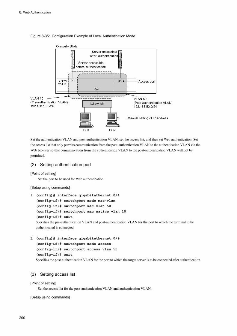
8. Web Authentication
Figure 8-35: Configuration Example of Local Authentication Mode
Set the authentication VLAN and post-authentication VLAN, set the access list, and then set Web authentication. Set the access list that only permits communication from the post-authentication VLAN to the authentication VLAN via the Web browser so that communication from the authentication VLAN to the post-authentication VLAN will not be permitted.
(2) Setting authentication port
[Point of setting]Set the port to be used for Web authentication.
[Setup using commands]
1. (config)# interface gigabitethernet 0/4
(config-if)# switchport mode mac-vlan
(config-if)# switchport mac vlan 50
(config-if)# switchport mac native vlan 10
(config-if)# exit
Specifies the pre-authentication VLAN and post-authentication VLAN for the port to which the terminal to be authenticated is connected.
2. (config)# interface gigabitethernet 0/9
(config-if)# switchport mode access
(config-if)# switchport access vlan 50
(config-if)# exit
Specifies the post-authentication VLAN for the port to which the target server is to be connected after authentication.
(3) Setting access list
[Point of setting]Set the access list for the post-authentication VLAN and authentication VLAN.
[Setup using commands]
200

8. Web Authentication
1. (config)# ip access-list extended 100
(config-ext-nacl)# permit ip 192.168.10.0 0.0.0.255 192.168.10.0 0.0.0.255
(config-ext-nacl)# deny ip any any
(config-ext-nacl)# exit
(config)# interface vlan 10
(config-if)# ip access-group 100 in
(config-if)# exit
Sets the access list so that communication from the authentication VLAN to the post-authentication VLAN will not be permitted.
2. (config)# ip access-list extended 150
(config-ext-nacl)# permit tcp 192.168.50.0 0.0.0.255 host 192.168.10.254 eq
http
(config-ext-nacl)# permit ip 192.168.50.0 0.0.0.255 any
(config-ext-nacl)# deny ip any any
(config-ext-nacl)# exit
(config)# interface vlan 50
(config-if)# ip access-group 150 in
(config-if)# exit
Sets the access list for communication from the post-authentication VLAN to the authentication VLAN.
(4) Setting Web authentication
[Point of setting]Set the Web authentication configuration command to enable Web authentication.
[Setup using commands]
1. (config)# web-authentication vlan 50
Sets VLAN ID using the configuration command that sets the post-authentication VLAN for Web authentication.
2. (config)# web-authentication system-auth-control
Starts Web authentication.
(5) Configuration for Using Local Authentication Mode + Built-in DHCP Server
A setting example of configuring Web authentication using the local authentication mode and built-in DHCP server is shown in the figure below. IP addresses of terminals (PC1, PC2) should be assigned by the built-in DHCP server function on the LANSW module.
201

8. Web Authentication
Figure 8-36: Configuration Example for Using Local Authentication Mode + Built-in DHCP
Set the authentication VLAN and post-authentication VLAN, set the access list and DHCP server, and then set Web authentication. Set the access list that only permits communication from the post-authentication VLAN to the authentication VLAN via the Web browser so that communication from the authentication VLAN to the post-authentication VLAN will not be permitted.
(6) Setting authentication port
[Point of setting]Set the port to be used for Web authentication.
[Setup using commands]
1. (config)# interface gigabitethernet 0/4
(config-if)# switchport mode mac-vlan
(config-if)# switchport mac vlan 50
(config-if)# switchport mac native vlan 10
(config-if)# exit
Specifies the pre-authentication VLAN and post-authentication VLAN for the port to which the terminal to be authenticated is connected.
2. (config)# interface range gigabitethernet 0/9-10
(config-if-range)# switchport mode access
(config-if-range)# switchport access vlan 50
(config-if-range)# exit
Specifies the post-authentication VLAN for the port to which the target server is to be connected after authentication.
202

8. Web Authentication
(7) Setting access list
[Point of setting]Set the access list for the post-authentication VLAN and authentication VLAN.
[Setup using commands]
1. (config)# ip access-list extended 100
(config-ext-nacl)# permit udp 0.0.0.0 0.0.0.0 host 255.255.255.255 eq bootps
(config-ext-nacl)# permit ip 192.168.10.0 0.0.0.255 192.168.10.0 0.0.0.255
(config-ext-nacl)# deny ip any any
(config-ext-nacl)# exit
(config)# interface vlan 10
(config-if)# ip access-group 100 in
(config-if)# exit
Sets the access list so that communication from the authentication VLAN to the post-authentication VLAN will not be permitted.
2. (config)# ip access-list extended 150
(config-ext-nacl)# permit tcp 192.168.50.0 0.0.0.255 host 192.168.10.254 eq
http
(config-ext-nacl)# permit udp 0.0.0.0 0.0.0.0 host 255.255.255.255
(config-ext-nacl)# permit udp 0.0.0.0 0.0.0.0 host 192.168.10.254
(config-ext-nacl)# permit udp 0.0.0.0 0.0.0.0 host 192.168.50.254
(config-ext-nacl)# permit ip 192.168.50.0 0.0.0.255 any
(config-ext-nacl)# deny ip any any
(config-ext-nacl)# exit
(config)# interface vlan 50
(config-if)# ip access-group 150 in
(config-if)# exit
Sets the access list so that relay will be permitted for communication from the post-authentication VLAN to the authentication VLAN via the Web browser only.
(8) Setting DHCP server
[Point of setting]Set the DHCP server to distribute IP addresses to terminals.
[Setup using commands]
1. (config)# service dhcp vlan 10
(config)# ip dhcp excluded-address 192.168.10.1
(config)# ip dhcp excluded-address 192.168.10.254
(config)# ip dhcp pool POOL10
(dhcp-config)# network 192.168.10.0/24
(dhcp-config)# lease 0 0 1
(dhcp-config)# default-router 192.168.10.1
(dhcp-config)# exit
Sets the pre-authentication VLAN on the DHCP server (to distribute IP address to be used for terminal authentication. Set default router IP address 192.168.10.1).
2. (config)# service dhcp vlan 50
203

8. Web Authentication
(config)# ip dhcp excluded-address 192.168.50.1
(config)# ip dhcp excluded-address 192.168.50.254
(config)# ip dhcp pool POOL50
(dhcp-config)# network 192.168.50.0/24
(dhcp-config)# lease 0 0 1
(dhcp-config)# default-router 192.168.50.1
(dhcp-config)# exit
Sets the post-authentication VLAN on the DHCP server (to distribute IP address to be used on the authenticated terminal. Set default router IP address 192.168.50.1).
(9) Setting Web authentication
[Point of setting]Set the Web authentication configuration command to enable Web authentication.
[Setup using commands]
1. (config)# web-authentication vlan 50
Sets VLAN ID using the configuration command that sets the post-authentication VLAN for Web authentication.
2. (config)# web-authentication system-auth-control
Starts Web authentication.
(10) Configuration for Using RADIUS Authentication Mode + Built-in DHCP Server
A setting example of configuring Web authentication using the RADIUS authentication mode and built-in DHCP server is shown in the figure below. IP addresses of terminals (PC1, PC2) should be assigned by the built-in DHCP server function on the LANSW module.
204

8. Web Authentication
Figure 8-37: Configuration Example of Using RADIUS Authentication Mode for Web Authentication + Built-in DHCP
Set the authentication VLAN and post-authentication VLAN, set the access list and DHCP server, and then set Web authentication. Set the access list that only permits communication from the post-authentication VLAN to the authentication VLAN via the Web browser so that communication from the authentication VLAN to the post-authentication VLAN will not be permitted.
(11) Setting authentication port
[Point of setting]Set the port to be used for Web authentication.
[Setup using commands]
1. (config)# interface gigabitethernet 0/4
(config-if)# switchport mode mac-vlan
(config-if)# switchport mac vlan 50
(config-if)# switchport mac native vlan 10
(config-if)# exit
Specifies the pre-authentication VLAN and post-authentication VLAN for the port to which the terminal to be authenticated is connected.
2. (config)# interface range gigabitethernet 0/9-10
205

8. Web Authentication
(config-if-range)# switchport mode access
(config-if-range)# switchport access vlan 50
(config-if-range)# exit
Specifies the post-authentication VLAN for the port to which the target server is to be connected after authentication.
(12) Setting access list
[Point of setting]Set the access list for the post-authentication VLAN and authentication VLAN.
[Setup using commands]
1. (config)# ip access-list extended 100
(config-ext-nacl)# permit udp 0.0.0.0 0.0.0.0 host 255.255.255.255 eq bootps
(config-ext-nacl)# permit ip 192.168.10.0 0.0.0.255 192.168.10.0 0.0.0.255
(config-ext-nacl)# deny ip any any
(config-ext-nacl)# exit
(config)# interface vlan 10
(config-if)# ip access-group 100 in
(config-if)# exit
Sets the access list so that communication from the authentication VLAN to the post-authentication VLAN will not be permitted.
2. (config)# ip access-list extended 150
(config-ext-nacl)# permit tcp 192.168.50.0 0.0.0.255 host 192.168.10.254 eq
http
(config-ext-nacl)# permit udp 0.0.0.0 0.0.0.0 host 255.255.255.255
(config-ext-nacl)# permit udp 0.0.0.0 0.0.0.0 host 192.168.10.254
(config-ext-nacl)# permit udp 0.0.0.0 0.0.0.0 host 192.168.50.254
(config-ext-nacl)# permit ip 192.168.50.0 0.0.0.255 any
(config-ext-nacl)# deny ip any any
(config-ext-nacl)# exit
(config)# interface vlan 50
(config-if)# ip access-group 150 in
(config-if)# exit
Sets the access list so that relay will be permitted for communication from the post-authentication VLAN to the authentication VLAN via the Web browser only.
(13) Setting DHCP server
[Point of setting]Set the DHCP server to distribute IP addresses to terminals.
[Setup using commands]
1. (config)# service dhcp vlan 10
(config)# ip dhcp excluded-address 192.168.10.1
(config)# ip dhcp excluded-address 192.168.10.254
(config)# ip dhcp pool POOL10
(dhcp-config)# network 192.168.10.0/24
(dhcp-config)# lease 0 0 1
206

8. Web Authentication
(dhcp-config)# default-router 192.168.10.1
(dhcp-config)# exit
Sets the pre-authentication VLAN on the DHCP server (to distribute IP addresses to be used for terminal authentication. Set default router IP address 192.168.10.1).
2. (config)# service dhcp vlan 50
(config)# ip dhcp excluded-address 192.168.50.1
(config)# ip dhcp excluded-address 192.168.50.254
(config)# ip dhcp pool POOL50
(dhcp-config)# network 192.168.50.0/24
(dhcp-config)# lease 0 0 1
(dhcp-config)# default-router 192.168.50.1
(dhcp-config)# exit
Sets the post-authentication VLAN on the DHCP server (to distribute IP addresses to be used on the authenticated terminal. Set default router IP address 192.168.50.1).
(14) Setting Web authentication
[Point of setting]Set the Web authentication configuration command to enable Web authentication.
[Setup using commands]
1. (config)# web-authentication vlan 50
Sets VLAN ID using the configuration command that sets the post-authentication VLAN for Web authentication.
2. (config)# aaa authentication web-authentication default group radius
(config)# radius-server host 192.168.10.200 key "webauth"
Sets the IP address and RADIUS key for user authentication on the RADIUS server.
3. (config)# web-authentication system-auth-control
Starts Web authentication.
(15) Configuration for Using RADIUS Authentication Mode + External DHCP Server + Multiple Post-authentication VLANs
The figure below shows a configuration example for using the RADIUS authentication mode and external DHCP server and setting multiple post-authentication VLANs. IP addresses of terminals (PC1, PC2) are assumed to be assigned by the external DHCP server.
207

8. Web Authentication
Figure 8-38: Configuration Example of Using RADIUS Authentication Mode for Web Authentication + External DHCP Server + Multiple Post-authentication VLANs
Set the authentication VLAN and post-authentication VLAN, set the access list and the DHCP server, and then set Web authentication. Set the access list that only permits communication from the post-authentication VLAN to the authentication VLAN via the Web browser so that communication from the authentication VLAN to the post-authentication VLAN will not be permitted.
Set the access list to disable the communication between post-authentication VLANs.
(16) Setting authentication port
[Point of setting]Set the port to be used for Web authentication.
[Setup using commands]
1. (config)# interface gigabitethernet 0/4
(config-if)# switchport mode mac-vlan
(config-if)# switchport mac vlan 50,60
(config-if)# switchport mac native vlan 10
(config-if)# exit
Specifies the pre-authentication VLAN and post-authentication VLAN for the port to which the terminal to be authenticated is connected.
2. (config)# interface gigabitethernet 0/9
(config-if)# switchport mode access
208

8. Web Authentication
(config-if)# switchport access vlan 50
(config-if)# exit
Specifies the post-authentication VLAN for the port to which the target server is to be connected after authentication.
3. (config)# interface gigabitethernet 0/10
(config-if)# switchport mode access
(config-if)# switchport access vlan 60
(config-if)# exit
Specifies the post-authentication VLAN for the port to which the target server is to be connected after authentication.
(17) Setting access list
[Point of setting]Set the access list for the post-authentication VLAN and authentication VLAN.
[Setup using commands]
1. (config)# ip access-list extended 100
(config-ext-nacl)# permit udp 0.0.0.0 0.0.0.0 host 255.255.255.255 eq bootps
(config-ext-nacl)# permit ip 192.168.10.0 0.0.0.255 192.168.10.0 0.0.0.255
(config-ext-nacl)# deny ip any any
(config-ext-nacl)# exit
(config)# interface vlan 10
(config-if)# ip access-group 100 in
(config-if)# exit
Sets the access list so that communication from the authentication VLAN to the post-authentication VLAN will not be permitted.
2. (config)# ip access-list extended 150
(config-ext-nacl)# permit tcp 192.168.50.0 0.0.0.255 host 192.168.10.254 eq
http
(config-ext-nacl)# permit udp 0.0.0.0 0.0.0.0 host 255.255.255.255
(config-ext-nacl)# permit udp 0.0.0.0 0.0.0.0 host 192.168.10.254
(config-ext-nacl)# permit udp 0.0.0.0 0.0.0.0 host 192.168.50.254
(config-ext-nacl)# permit ip 192.168.50.0 0.0.0.255 any
(config-ext-nacl)# deny ip any any
(config-ext-nacl)# exit
(config)# interface vlan 50
(config-if)# ip access-group 150 in
(config-if)# exit
Sets the access list to allow the post-authentication VLAN (VLAN ID 50) to relay the communication from the Web browser to the authentication VLAN and disable the communication to the other post-authentication VLAN (VLAN ID 60).
3. (config)# ip access-list extended 160
(config-ext-nacl)# permit tcp 192.168.60.0 0.0.0.255 host 192.168.10.254 eq
http
(config-ext-nacl)# permit udp 0.0.0.0 0.0.0.0 host 255.255.255.255
(config-ext-nacl)# permit udp 0.0.0.0 0.0.0.0 host 192.168.10.254
(config-ext-nacl)# permit udp 0.0.0.0 0.0.0.0 host 192.168.60.254
209

8. Web Authentication
(config-ext-nacl)# permit ip 192.168.60.0 0.0.0.255 any
(config-ext-nacl)# deny ip any any
(config-ext-nacl)# exit
(config)# interface vlan 60
(config-if)# ip access-group 160 in
(config-if)# exit
Sets the access list to allow the post-authentication VLAN (VLAN ID 60) to relay the communication from the Web browser to the authentication VLAN and disable the communication to the other post-authentication VLAN (VLAN ID 50).
(18) Setting DHCP relay agent
[Point of setting]Set the DHCP relay agent to distribute IP addresses to terminals.
[Setup using commands]
1. (config)# interface vlan 10
(config-if)# ip address 192.168.10.254 255.255.255.0
(config-if)# ip helper-address 192.168.10.100
(config-if)# exit
Sets a DHCP relay agent for the pre-authentication VLAN.
2. (config)# interface vlan 50
(config-if)# ip address 192.168.50.254 255.255.255.0
(config-if)# ip helper-address 192.168.10.100
(config-if)# exit
Sets a DHCP relay agent for the post-authentication VLAN (VLAN ID 50).
3. (config)# interface vlan 60
(config-if)# ip address 192.168.60.254 255.255.255.0
(config-if)# ip helper-address 192.168.10.100
(config-if)# exit
Sets a DHCP relay agent for the post-authentication VLAN (VLAN ID 60).
(19) Setting Web authentication
[Point of setting]Set the Web authentication configuration command to enable Web authentication.
[Setup using commands]
1. (config)# web-authentication vlan 50
(config)# web-authentication vlan 60
Sets VLAN ID using the configuration command that sets the post-authentication VLAN for Web authentication.
2. (config)# aaa authentication web-authentication default group radius
(config)# radius-server host 192.168.10.200 key "webauth"
Sets the IP address and RADIUS key for user authentication on the RADIUS server.
3. (config)# web-authentication system-auth-control
210

8. Web Authentication
Starts Web authentication.
8.2.5 Setting Web Authentication ParameterThis section describes the parameter setting available for Web authentication.
(1) Setting maximum authentication time
[Point of setting]Set the time for forced logout of the authenticated terminal.
[Setup using commands]
1. (config)# web-authentication max-timer 60
Sets the forced logout time to 60 minutes.
(2) Setting number of authenticated users
[Point of setting]Set the number of users that can be authenticated with Web authentication.
[Setup using commands]
1. (config)# web-authentication max-user 5
Sets the number of users that can be authenticated in Web authentication to 5.
(3) Setting RADIUS server
[Point of setting]Set the RADIUS server to be used in the RADIUS authentication mode.
[Setup using commands]
1. (config)# aaa authentication web-authentication default group radius
Sets the user authentication using the RADIUS server.
(4) Setting accounting
[Point of setting]Set accounting count for Web authentication.
[Setup using commands]
1. (config)# aaa accounting web-authentication default start-stop group radius
Sets accounting count on the RADIUS server.
8.2.6 Method of Exclusion from AuthenticationExplained below is the setting for the exclusion from the MAC authentication.
(1) Setting the Port to Be Excluded from the Static VLAN Mode Authentication
Set the port that is allowed for communication without being authenticated in the static VLAN mode.
211

8. Web Authentication
[Point of setting]The port excluded from the authentication is not set as the authentication one.
[Setup using commands]
1. (config)# vlan 10
(config-vlan)# state active
(config-vlan)# exit
(config)# interface gigabitethernet 0/4
(config-if)# switchport mode access
(config-if)# switchport access vlan 10
(config-if)# mac-authentication port
(config-if)# exit
(config)# interface gigabitethernet 0/10
(config-if)# switchport mode access
(config-if)# switchport access vlan 10
(config-if)# exit
Port 0/4 for which VLAN ID 10 handled in the static VLAN mode is set as the authentication port. Moreover, make the setting so that port 0/10 is allowed for communication without being authenticated.
(2) Setting the Terminal Excluded from the Static VLAN Mode Authentication
Set the MAC address of the terminal that is allowed for communication without being authenticated in the static VLAN mode, as follows:
[Point of setting]Register the MAC address of the terminal excluded from authentication, in the MAC address table.
[Setup using commands]
1. (config)# vlan 10
(config-vlan)# state active
(config-vlan)# exit
(config)# mac-address-table static 0012.e212.3456 vlan 10 interface
gigabitethernet 0/10
Set the MAC address that is allowed for communication without being authenticated, for port 0/10 of VLAN ID 10.
(3) Setting the Port Excluded from Authentication in the Dynamic VLAN Mode
Set the port that is allowed for communication without being authenticated in the dynamic VLAN mode, as follows:
[Point of setting]Do not set the port excluded from authentication, as the authentication port.
[Setup using commands]
1. (config)# vlan 10
(config-vlan)# state active
(config-vlan)# exit
(config)# interface gigabitethernet 0/4
(config-if)# switchport mode mac-vlan
(config-if)# switchport mac vlan 20
(config-if)# switchport mac native-vlan 10
212

8. Web Authentication
(config-if)# mac-authentication port
(config-if)# exit
(config)# interface gigabitethernet 0/10
(config-if)# switchport mode access
(config-if)# switchport access vlan 20
(config-if)# exit
Set, as the authentication port, port 0/4 for which MAC VLAN ID 20 handled in the dynamic VLAN mode is set. Make the setting so that port 0/10 is allowed for communication without being authenticated.
(4) Setting the Terminal Excluded from Dynamic VLAN Mode Authentication
Set the MAC address of the terminal that is allowed for communication without being authenticated in the dynamic VLAN mode, as follows:
[Point of setting]Register the MAC address of the terminal excluded from authentication, in MAC VLAN and the MAC address table.
[Setup using commands]
1. (config)# vlan 20 mac-based
(config-vlan)# mac-address 0012.e212.3456
(config-vlan)# exit
(config)# mac-address-table static 0012.e212.3456 vlan 20 interface
gigabitethernet 0/10
Set the MAC address of the terminal that is allowed for communication without being authenticated, for port 0/10 of MAC VLAN ID 20.
213

8. Web Authentication
8.3 Operation
8.3.1 List of Operation CommandsThe list of Web authentication operation commands is shown in the table below.
Table 8-9: List of Operation Commands
8.3.2 Displaying Web Authentication Setting InformationUsing the "show web-authentication" command, display the Web authentication setting information.
Command Description
set web-authentication user Adds the user ID to be used in Web authentication.
set web-authentication passwd Changes the password of the registered user.
set web-authentication vlan Changes VLAN ID of the registered user.
remove web-authentication user Deletes the registered user ID.
commit web-authentication Reflects the contents of addition/change to the built-in Web authentication database.
store web-authentication Creates the backup file of the built-in Web authentication database.
load web-authentication Restores the built-in Web authentication database from the backup file.
show web-authentication user Displays the contents of registration in the built-in Web authentication database or the information during addition/change.
clear web-authentication auth-state Performs forced logout of the authenticated user.
show web-authentication login Displays the authenticated account log.
clear web-authentication login Clears the authenticated account log.
show web-authentication statistics Displays statistics information of Web authentication.
clear web-authentication statistics Clears statistics information of Web authentication.
show web-authentication logging Displays operation log of Web authentication.
clear web-authentication logging Clears operation log of Web authentication.
set web-authentication html-files The specified Web attestation screen file is registered.
clear web-authentication html-files The registered Web attestation screen file is deleted.
show web-authentication html-files The file name, the size of the file, and the registration date of the registeredWeb attestation screen file are displayed.
restart web-authentication Restarts the Web authentication program.
dump protocols web-authentication Collects dump information of Web authentication.
214
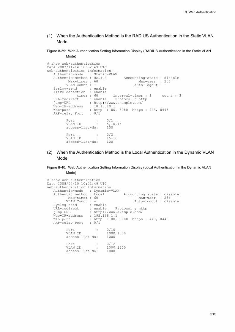
8. Web Authentication
(1) When the Authentication Method is the RADIUS Authentication in the Static VLAN Mode:
Figure 8-39: Web Authentication Setting Information Display (RADIUS Authentication in the Static VLAN Mode)
# show web-authenticationDate 2007/11/14 10:52:49 UTCweb-authentication Information: Authentic-mode : Static-VLAN Authentic-method : RADIUS Accounting-state : disable Max-timer : 60 Max-user : 256 VLAN Count : - Auto-logout : - Syslog-send : enable Alive-detection : enable timer : 60 interval-timer : 3 count : 3 URL-redirect : enable Protocol : http jump-URL : http://www.example.com/ Web-IP-address : 10.10.10.1 Web-port : http : 80, 8080 https : 443, 8443 ARP-relay Port : 0/1 Port : 0/1 VLAN ID : 5,10,15 access-list-No: 100 Port : 0/2 VLAN ID : 15-16 access-list-No: 100
(2) When the Authentication Method is the Local Authentication in the Dynamic VLAN Mode:
Figure 8-40: Web Authentication Setting Information Display (Local Authentication in the Dynamic VLAN Mode)
# show web-authenticationDate 2008/04/10 10:52:49 UTCweb-authentication Information: Authentic-mode : Dynamic-VLAN Authentic-method : Local Accounting-state : disable Max-timer : 60 Max-user : 256 VLAN Count : - Auto-logout : disable Syslog-send : enable URL-redirect : enable Protocol : http jump-URL : http://www.example.com/ Web-IP-address : 192.168.1.1 Web-port : http : 80, 8080 https : 443, 8443 ARP-relay Port : 0/1 Port : 0/10 VLAN ID : 1000,1500 access-list-No: 1000 Port : 0/12 VLAN ID : 1000,1500 access-list-No: 1000
215

8. Web Authentication
(3) When the Authentication Method is the RADIUS Authentication in the Dynamic VLAN Mode:
Figure 8-41: Web Authentication Setting Information Display (RADIUS Authentication in the Dynamic VLAN Mode)
# show web-authenticationDate 2008/04/10 10:52:49 UTCweb-authentication Information: Authentic-mode : Dynamic-VLAN Authentic-method : RADIUS Accounting-state : enable Max-timer : 60 Max-user : 256 VLAN Count : - Auto-logout : disable Syslog-send : enable URL-redirect : enable Protocol : http jump-URL : http://www.example.com/ Web-IP-address : 192.168.1.1 Web-port : http : 80, 8080 https : 443, 8443 ARP-relay Port : 0/1 Port : 0/10 VLAN ID : 1000,1500 access-list-No: 1000 Port : 0/12 VLAN ID : 1000,1500 access-list-No: 1000
(4) When VLAN Is Registered in the Legacy Mode and the Authentication Method Is the Local Authentication:
Figure 8-42: Web Authentication Setting Information Display (Local Authentication)
# show web-authenticationDate 2007/11/14 10:52:49 UTCweb-authentication Information: Authentic-mode : Legacy Authentic-method : Local Accounting-state : disable Max-timer : 60 Max-user : 256 VLAN Count : 16 Auto-logout : disable Syslog-send : enable jump-URL : http://www.example.com/ Web-port : http : 80 https : 443 VLAN Information: VLAN ID : 5, 10, 15, 20, 25, 30, 35, 401000-1007
(5) When VLAN Is Registered in the Legacy Mode and the Authentication Method Is the RADIUS Authentication:
Figure 8-43: Web Authentication Setting Information Display (RADIUS Authentication)
# show web-authenticationDate 2007/11/14 10:52:49 UTCweb-authentication Information: Authentic-mode : Legacy Authentic-method : RADIUS Accounting-state : disable Max-timer : 60 Max-user : 256 VLAN Count : 16 Auto-logout : disable Syslog-send : enable jump-URL : http://www.example.com/ Web-port : http : 80 https : 443 VLAN Information: VLAN ID : 5, 10, 15, 20, 25, 30, 35, 401000-1007
216

8. Web Authentication
8.3.3 Displaying Web Authentication StatusUsing the "show web-authentication statistics" command, display the Web authentication status and the status of communication with RADIUS.
Figure 8-44: Displaying Web Authentication
# show web-authentication statisticsDate 2006/08/12 11:10:49 UTCweb-authentication Information: Authentication Request Total : 100 Authentication Current Count : 10 Authentication Error Total : 30RADIUS web-authentication Information:[RADIUS frames] TxTotal : 10 TxAccReq : 10 TxError : 0 RxTotal : 30 RxAccAccpt: 10 RxAccRejct: 10 RxAccChllg: 10 RxInvalid : 0Account web-authentication Information:[Account frames] TxTotal : 10 TxAccReq : 10 TxError : 0 RxTotal : 20 RxAccResp : 10 RxInvalid : 0
8.3.4 Displaying Web Authentication Login StatusUsing the "show web-authentication login" command, display the Web authentication login status.
(1) Static VLAN mode
Figure 8-45: Displaying Web Authentication Login Status(Static VLAN mode)
# show web-authentication loginDate 2007/11/14 10:52:49 UTC Total user counts:2 username VLAN MAC address Port IP address Login time Limit time USER00123456789 3 0012.e200.9166 0/5 192.168.0.1 2007/11/14 09:58:04 UTC 00:10:20 USER01 4094 0012.e268.7527 0/6 192.168.1.10 2007/11/14 10:10:23 UTC 00:20:35
(2) Dynamic VLAN mode
Figure 8-46: Displaying Web Authentication Login Status(Dynamic VLAN mode)
# show web-authentication loginDate 2008/04/10 10:52:49 UTC Total user counts:2 username VLAN MAC address Login time Limit time USER00123456789 3 0012.e200.9166 2008/04/10 09:58:04 UTC 00:10:20 USER01 4094 0012.e268.7527 2008/04/10 10:10:23 UTC 00:20:35
217

8. Web Authentication
(3) Legacy mode
Figure 8-47: Displaying Web Authentication Login Status(Legacy mode)
# show web-authentication loginDate 2007/11/14 10:52:49 UTC Total user counts:2 username VLAN MAC address Login time Limit time USER00123456789 3 0012.e200.9166 2007/11/14 09:58:04 UTC 00:10:20 USER01 4094 0012.e268.7527 2007/11/14 10:10:23 UTC 00:20:35
8.3.5 Creating Built-in Web Authentication DatabaseCreate the built-in Web authentication database after environment setting of the Web authentication system and configuration setting are completed. Also, modify the user information that is already registered in the built-in Web authentication database.
(1) Registering users
For each user to be authenticated, register the user ID, password, and VLAN ID using the "set web-authentication user" command. In the example below, five users (USER01 to USER05) are registered.
[Command input]# set web-authentication user USER01 PAS0101 100# set web-authentication user USER02 PAS0200 100# set web-authentication user USER03 PAS0300 100# set web-authentication user USER04 PAS0320 100# set web-authentication user USER05 PAS0400 100
(2) Changing/deleting the user information
The password and VLAN ID of the registered user are changed/deleted as described below.
(a) Changing the password
[Command input]# set web-authentication passwd USER01 PAS0101 PPP4321Changes the password of user ID (USER01) from PAS0101 to PPP4321.
# set web-authentication passwd USER02 PAS0200 BBB1234Changes the password of user ID (USER02) from PAS0200 to BBB1234.
(b) Changing the VLAN ID
[Command input]# set web-authentication vlan BBB1234 200Changes VLAN ID of user ID (BBB1234) to 200.
(c) Deleting the user
[Command input]# remove web-authentication user PPP4321Deletes user ID (PPPP4321).
218

8. Web Authentication
(3) Applying to the built-in Web authentication database
Apply the user information registered or changed using the "set web-authentication" command or "remove web-authentication" command to the built-in Web authentication database.
[Command input]# commit web-authentication
8.3.6 Backing Up Built-in Web Authentication DatabaseBacking up the built-in Web authentication database and restoring from the backup file are described below.
(1) Backing up the built-in Web authentication database
Using operation command "store web-authentication", create a backup file (backupfile in the example below) from the built-in Web authentication database.
[Command input]# store web-authentication backupfileBackup web-authentication user data. Are you sure? (y/n): y#
(2) Restoring the built-in Web authentication database
Using operation command "load web-authentication", create the built-in Web authentication database from the backup file (backupfile in the example below).
[Command input]# load web-authentication backupfileRestore web-authentication user data. Are you sure? (y/n): y#
8.3.7 Displaying Web Authentication Login StatusThe following procedure is used to register web authentication screens.
1. Create each web authentication screen file on the external device (such as PC).2. Log in to this device and create a directory for saving web authentication screens in the current directory.3. Save the screen file in the directory (created in step 2) through file transfer or MC.4. Use the "set web-authentication html-files" command to register web authentication screens.
Figure 8-48: Registering Web Authentication Screens
# mkdir docs ...1# set web-authentication html-files docsWould you wish to install new html-files ? (y/n):yexecuting...Install complete.#
1. Create a directory (docs) and place the particular file in the directory.
8.3.8 Deleting Registered Web Authentication ScreensThe following procedure is used to register web authentication screens.
219
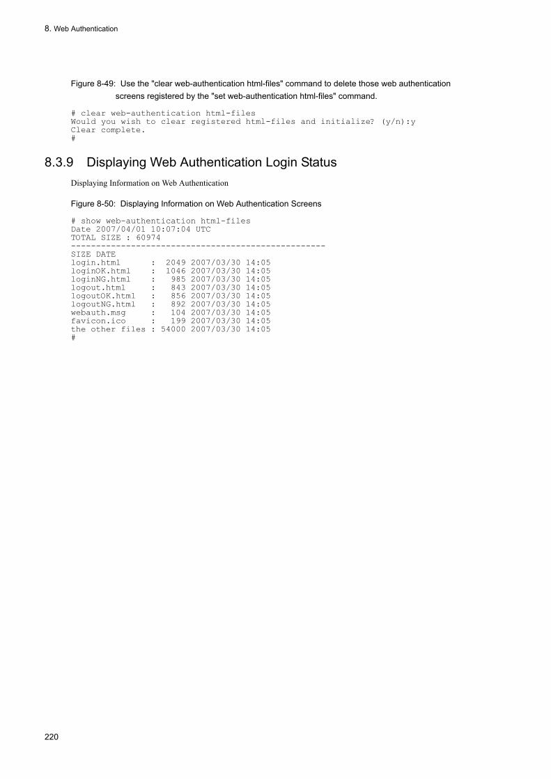
8. Web Authentication
Figure 8-49: Use the "clear web-authentication html-files" command to delete those web authentication screens registered by the "set web-authentication html-files" command.
# clear web-authentication html-filesWould you wish to clear registered html-files and initialize? (y/n):yClear complete.#
8.3.9 Displaying Web Authentication Login StatusDisplaying Information on Web Authentication
Figure 8-50: Displaying Information on Web Authentication Screens
# show web-authentication html-filesDate 2007/04/01 10:07:04 UTCTOTAL SIZE : 60974---------------------------------------------------SIZE DATElogin.html : 2049 2007/03/30 14:05loginOK.html : 1046 2007/03/30 14:05loginNG.html : 985 2007/03/30 14:05logout.html : 843 2007/03/30 14:05logoutOK.html : 856 2007/03/30 14:05logoutNG.html : 892 2007/03/30 14:05webauth.msg : 104 2007/03/30 14:05favicon.ico : 199 2007/03/30 14:05the other files : 54000 2007/03/30 14:05#
220

8. Web Authentication
8.4 Guide to Creating Web Authentication Screens
The following is a list of the names of files corresponding to those screens that can be changed with the web authentication screen replacement function.
• Login screen (file name: login.html)• Logout screen (file name: logout.html)• Successful login screen (file name: loginOK.html)• Unsuccessful login screen (file name: loginNG.html)• Completed logout screen (file name: logoutOK.html)• Unsuccessful logout screen (file name: logoutNG.html)
Each web authentication screen file should be created in the HTML format.
For HTML, you can use JavaScript or another language operating only the client terminal alone, but you cannot use any language gaining access to the server. Also, perl and other CGIs must not be specified.
However, the login and logout screens required a description for the interface with web authentication. For details about the login and logout screens, see Section 7.4.1, "Login Screen (login.html)" and section 7.4.2, "Logout Screen (logout.html)."
Note also that you can change the authentication error messages listed in Table 7-1, "Relationship Between Authentication Error Messages and Error Causes". The names of files available are listed below. For how to create files, see Section 7.4.3, "Authentication Error Message File (webauth.msg)".
• Authentication error message (file name: webauth.msg)
Additionally, you can change the icon displayed in the web browser's favorite.
• Icon (file name: favicon.ico) displayed in the web browser's favorite folder.
[note]The file names for those changeable screens and authentication error messages must always be the same as the file names shown above.
8.4.1 Login Screen (login.html)This screen is used to request the client to enter the user ID and password when you log in with web authentication.
(1) Setting conditions
When creating an HTML file on the login screen, be sure to enter the following description.
Table 8-10: Setting Required for the Login Screen
Contents Meaning
<form name="Login" method="post" action="/cgi-bin/Login.cgi"></form>
The description is intended to direct login operation to web authentication. Do not change this description.
<input type="text" name="uid" size="40" maxlength="32"autocomplete="OFF" />
It is a description used to specify the user ID. You must not change any description other than "size" and "maxlength". The setting must be inside the above pair of <form>and </form>. For "maxlength", be sure to set a value equal to, or larger than, 6.
221

8. Web Authentication
[note]
When relating another file to the "login.html" file, the name of the target file must begin with a slash (/).
(example) < img src="/image_file.gif" >
(2) Setting example
The following figure shows an example of the source appearing on the login screen (login.html).
<input type="submit" value="login" /> It is a description used to log in for web authentication. You must not change any description other than "size" and "maxlength". The setting must be inside the above pair of <form>and </form>.
<input type="text" name="uid" size="40" maxlength="32" autocomplete="OFF" />
It is a description used to specify the user ID. You must not change any description other than "size" and "maxlength". The setting must be inside the above pair of <form>and </form>. For "maxlength", be sure to set a value equal to, or larger than, 6.
Contents Meaning
222

8. Web Authentication
Figure 8-51: Example of the source appearing on the login screen (login.html).
(3) Example of displaying login screen
The following figure shows the example of displaying the login screen.
223

8. Web Authentication
Figure 8-52: Example of displaying login screen
8.4.2 Logout Screen (logiouthtml)This screen enables a client in the process of logging in with the web authentication function to a make a logout request.
(1) Setting conditions
When creating an HTML file on the logout screen, be sure to enter the following description.
Table 8-11: Setting Required for the Logout Screen
[note]
When relating another file to the "login.html" file, the name of the target file must begin with a slash (/).
(example) < img src="/image_file.gif" >
(2) Example of Setting
The following figure shows an example of the source appearing on the logout screen (logout.html).
Contents Meaning
<form name="Logout" method="post" action="/cgi-bin/Login.cgi"></form>
The description is intended to direct logout operation to web authentication. Do not change this description.
<input type="submit" value="login" /> It is a description used to log out for web authentication. You must not change any description other than "size" and "maxlength". The setting must be inside the above pair of <form>and </form>.
224

8. Web Authentication
Figure 8-53: Example of the source appearing on the logout screen (logout.html).
(3) Example of displaying logout screen
The following figure shows the example of displaying the logout screen.
225

8. Web Authentication
Figure 8-54: Example of displaying login screen
8.4.3 File for authentication error messagesThe authentication error message file (webauth.msg) contains a group of messages to be displayed on the response screen in reply to failure in a web authentication login or a web authentication logout.
To exchange authentication error messages having default settings, you need to create an authentication error message file that contains the nine lines of messages shown in the following table.
Table 8-12: Contents of each line of for authentication error messages
Line number content
1 This message is displayed if the user ID or password description specified during a login is wrong or if an authentication error occurs in the web authentication DB.[default message]"User ID or password is wrong.<BR>Please enter correct user ID and password."
2 This message is displayed if a Radius-based authentically error occurs.[default message]"RADIUS: Authentication reject."
3 This message is displayed if no connection between the Radius server and this device is established although, by configuration, Radius authentication is already set.[default message]"RADIUS: No authentication response."
4 This message is displayed if no login can be performed because of a wrong setup in the configuration of this device or a contention with another function. [default message]"You cannot login by this machine."
5 This message is displayed if there is a minor program-related fault. [default message]"Sorry, you cannot login just now. <BR> Please try again after a while."
226

8. Web Authentication
(1) Setting conditions• If only a linefeed line exists, the default error message is displayed.• When saving a file, you can enter the linefeed code by using "CR+LF" or "LF".• The maximum length of a message for one line is 512 single-byte characters (or 256 double-byte characters). The
number of characters shown here includes the "html" tag and the linefeed tag "<BR>". Note that any characters exceeding the limit of 512 single-byte characters will be ignored.
• If the authentication error message file contains 10 or more lines, then the content of line 10 and following
(2) Main points in creating an authentication error message file• The exact text described in an authentication error message file is used as the HTML text. Therefore, any HTML tags
described in an authentication error message will work that way.• Each message must be completed in a single line. If, therefore, you want to add a linefeed into the display image in
an error message, the linefeed tag "<BR>" in HTML must be inserted into the target point.
(3) Example of setting
The following figure shows an example of the source for the authentication error message file (webauth.msg)
Figure 8-55: example of the source for the authentication error message file (webauth.msg).
The user ID or password is incorrect.No authentication server can be found.You should consult your system administrator.There is a fault in the system setup.A system fault has occurred.Wait for a while and make another loginThe system involves a high load.No login has been performed.
(4) Example of displaying
The following figure shows an example of the unsuccessful login screen, which is displayed when a login fails because of an error in password length according to the authentication error message file explained above.
6 This message is displayed if there is a normal program-related fault. [default message]"The system error occurred. <br> Please contact the system administrator."
7 This message is displayed if there is a major program-related fault.[default message]"A fatal error occurred. <BR> Please inform the system administrator."
8 This message is displayed if the logout operation is unsuccessful due to, for example, a high CPU load.[default message]"Sorry, you cannot logout just now. <BR> Please try again after a while."
9 This message is displayed if a non-login user attempts to make a logout.[default message]"The client PC is not authenticated."
Line number content
227

8. Web Authentication
Figure 8-56: Example of the unsuccessful login screen being displayed (incorrect password length)
8.4.4 Tag unique to Web AuthenticationWriting the tag unique to web authentication into the HTML file on the web authentication screen makes it possible to display the login time and error message on the authentication screen
The following table shows combinations of configurable screens and tags unique to web authentication
Table 8-13: Special tag list
Tag descriptions
the content displayed on each screen
the login screen
the logout screen
the successful
login screen
the unsuccess
ful login screen
The completed
logout screen
the unsuccessful logout screen
<!-- Login_Time-->
login time*1 - - Y - - -
<!-- Logout_Time-->
logout time*2 - - Y - Y -
<!-- After_Vlan-->
the VLAN IDafterauthentication
- - Y - - -
228

8. Web Authentication
(Legend) Y: Displays something on the screen. N: Displays nothing on the screen.
*1 Time at which the login was successful
*2 A different screens has its own meaning. Successful login screen: Time at which an automatic logout is performed Completed logout screen: Time at which the operation of a logout is completed
*3 VLAN ID used for communication by the user after a successful login.
*4 Error factor attributed to an unsuccessful login or logout event.
For typical setup examples, refer to section 7.4.5, "Other Screen Samples".
8.4.5 Other Screen SamplesThe following shows sample sources for the web authentication screen (logoutNG.html)
(1) Successful login screen (loginOK.html)
The following figure shows some source and display examples on the successful login screen
<!--Error_Message-->
error message*4
- - - Y - Y
<!-- Redirect_URL -->
Jump destination URL after successful authentication
- - Y - - -
Tag descriptions
the content displayed on each screen
the login screen
the logout screen
the successful
login screen
the unsuccess
ful login screen
The completed
logout screen
the unsuccessful logout screen
229

8. Web Authentication
Figure 8-57: Successful login screen (loginOK.html)
[note]
When relating another file to the "loginOK.html" file, the name of the target file must begin with a slash (/).(example) < img src="/image_file.gif" >
230

8. Web Authentication
Figure 8-58: Example of displaying of Successful login screen
(2) The completed logout screen (logoutOK.html)
The following figure shows some source and display examples on the completed logout screen
Figure 8-59: Source examples on the completed logout screenen
[note]
When relating another file to the "logoutOK.html" file, the name of the target file must begin with a slash (/).(example) < img src="/image_file.gif" >
231

8. Web Authentication
Figure 8-60: Example of displaying of Complete logout screen
(3) The unsuccessful login / logout screen (loginOK.html / logoutNG.html)
The following figure shows some source and display examples on the completed logout screen
Figure 8-61: Source examples on the unsuccessful login / logout screenen
[note]
When relating another file to the "logoutNG.html" and "loginNG.html" file, the name of the target file must begin with a slash (/).(example) < img src="/image_file.gif" >
232

8. Web Authentication
Figure 8-62: Example of displaying of the unsuccessful login / logout screen
233

8. Web Authentication
234

9 MAC AuthenticationThe MAC authentication authenticates the transmission source MAC address of the frame that flowed and controls access to VLAN. This chapter gives an overview of the MAC authentication.
9.1 Description
9.2 Configuration
9.3 Operation
235

9. MAC Authentication
9.1 Description
A device such as a PC that enables inputs of a user ID and password can use IEEE802.1X and Web authentication. However, the MAC authentication authenticates devices such as a printer in which a user ID and password cannot be entered.
The transmission source MAC address of the frame that flows into the specified port is authenticated, and only the frame having the authenticated MAC address is allowed for communication.
The MAC authentication has the following authentication modes:
• Static VLAN modeThe MAC address of the terminal whose authentication was successful is registered in the MAC address table to allow communication with VLAN specified with the configuration.
• Dynamic VLAN modeThe MAC address of the terminal whose authentication was successful is registered in MAC VLAN and the MAC address table, and the switching is made to the VLAN that is allowed for communication after authentication.
Moreover, the MAC authentication methods include the following two types, either of which can be selected:
• Local authentication method using the authentication DB built in this device (called a built-in MAC authentication DB)
• oRADIUS authentication method in which an inquiry is made to a RADIUS server externally placed.
Moreover, the authentication result is recorded in the RADIUS server accounting function and syslog server.
9.1.1 Authentication Function
(1) Static VLAN Mode
In the MAC authentication, after the authentication is successful, communication is performed with the VLAN to which the port connecting to the terminal belongs.
(a) Local Authentication Method
The following two addresses are collated with each other: transmission source MAC address of the frame that flowed into from the port to be subjected to the MAC authentication and MAC address that is registered in the built-in MAC authentication DB. If they agree, the authentication is determined to be successful and communication is enabled.
236

9. MAC Authentication
Figure 9-1: Configuration of the Local Authentication Method in the Static VLAN Mode
The local authentication methods include the following two types: only MAC addresses are used for collation and the combination of the MAC address and VLAN ID is used for collation. To select each of them, the "mac-authentication vlan-check" configuration command can be used.
The following table lists the setting conditions when the MAC address and VLAN ID are used for collation:
Table 9-1: VLAN ID Collation of the Local Authentication Method in the Static VLAN Mode
(b) RADIUS Authentication Method
In the RADIUS authentication method, the following two addresses are collated: transmission source MAC address of the frame that flowed from the port to be subjected to the MAC authentication and the MAC address registered in the RADIUS server. If they agree, the authentication is determined to be successful and so communication is enabled.
configuration command setting Setting VLAN ID of the built-in MAC authentication DB
Is set Not set
Is set MAC address and VLAN ID are used for collation.
Only MAC addresses are used for collation.
Not set Only MAC addresses are used for collation. Only MAC addresses are used for collation.
237

9. MAC Authentication
Figure 9-2: Configuration of the RADIUS Authentication Method in the Static VLAN Mode
The RADIUS authentication methods include the following two types: only MAC addresses are used for collation and the combination of the MAC address and VLAN ID is used for collation. To select each of them, the "mac-authentication vlan-check" configuration command can be used.
The following table lists the setting conditions when the MAC address and VLAN ID are used for collation:
Table 9-2: VLAN ID Collation of the RADIUS Authentication Method in the Static VLAN Mode
The password used for an inquiry to RADIUS can be specified with the "mac-authentication password" configuration command. If this command is not set, the MAC address to be authenticated is used as the password.
(c) Authentication Release Method
Either of the following terminal authentication release methods is used:
• Authentication release when the maximum connection time is exceeded• Authentication release with the operation command• Authentication release caused by a link down of the authentication terminal connection port
Authentication release when the maximum connection time is exceededIf the maximum connection time set with the "mac-authentication max-timer" configuration command is exceeded, the authentication status is forcibly released. The authentication is released within one minute after this maximum connection time elapses.If the "mac-authentication max-timer" configuration command is used to shorten or lengthen the maximum connection time, this change is not applied to the terminal being currently authenticated and is valid from the next authentication.
Authentication release with the operation commandAuthentication can be forcibly released for each MAC address, using the "clear mac-authentication auth-state" operation command. If two or more VLAN IDs are authenticated using the same MAC address, all authentications
configuration command setting Operation
Is set MAC address and VLAN ID are used for collation.
Not set Only MAC addresses are used for collation.
238

9. MAC Authentication
having the same MAC address are released.
Authentication release caused by a link down of the authentication terminal connection portIf a link down of the port to which the authenticated terminal is connected is detected, the authentication of that terminal is released.
(d) Setting the Authentication Port
In the static VLAN mode, the following ports can be set as authentication targets:
• Access port• Trunk port
The Tagged frame that entered in the trunk port is handled as follows:
• If the authentication-time frame is the Tagged frame, communication is possible to the VLAN indicated with VLAN Tag after the authentication is successful.
• If the authentication-time frame is the Untagged frame, communication is possible to the native VLAN after the authentication is successful.
Figure 9-3: Handling the Tagged Frame
(2) Dynamic VLAN Mode
In the MAC authentication, after the authentication is successful, VLAN ID registered in the built-in MAC authentication DB or RADIUS is switched using the MACVLAN function to enable communication to the post-authentication VLAN.
Moreover, to perform communication within the pre-authentication VLAN, it is necessary to set the filter conditions required for communication, in the authentication-dedicated IPv4 access list.
239

9. MAC Authentication
(a) Local Authentication Method
In the local authentication method, the transmission source MAC address of the frame that flowed from the port to be subjected to the MAC authentication and the MAC address registered in the built-in MAC authentication DB are collated with each other. If they agree, the authentication is determined to be successful and they are registered in MAC VLAN and the MAC address table using VLAN ID registered in the built-in MAC authentication DB. Thus, communication with post-authentication VLAN is permitted.
Figure 9-4: Configuration of the Local Authentication Method in the Dynamic VLAN Mode
(b) RADIUS Authentication Method
In the RADIUS authentication method, the transmission source MAC address of the frame that flowed from the port to be subjected to the MAC authentication and the MAC address registered in the RADIUS server are collated with each other. If they agree, they are registered in MAC VLAN and the MAC address table using VLAN ID registered in RADIUS. Thus, communication with the post-authentication VLAN is permitted.
The password used for an inquiry to RADIUS can be specified with the "mac-authentication password" configuration command. If this command is not set, the MAC address to be authenticated is used as the password.
240

9. MAC Authentication
Figure 9-5: Configuration of the RADIUS Authentication Method in the Dynamic VLAN Mode
(c) Authentication Release Methods
One of the following terminal authentication release methods is used:
• Authentication release when the maximum connection time is exceeded• Authentication release with the operation command• Authentication release caused by the MAC address table aging of the authenticated terminal
Authentication release when the maximum connection time is exceededThe authentication status is forcibly released when the maximum connection time specified with the "mac-authentication max-timer" configuration command is exceeded. Authentication is released within one minute after this maximum connection time elapses.If the maximum connection time is shortened or lengthened with the "mac-authentication max-timer" configuration command, this change is not applied to the terminal being currently authenticated and is valid from the next authentication.
Authentication release with the operation commandAuthentication can be forcibly released for each MAC address using the "clear mac-authentication auth-state" operation command.
Authentication release caused by the MAC address table aging of the authenticated terminalThe MAC address table is periodically monitored for the authenticated terminal to check to see if access is made from the terminal. If no-access from the relevant terminal continues, the authentication status of the MAC authentication is forcibly released and the pre-authentication VLAN ID is used for accommodation. However, to prevent the authentication from being released due to an influence of an instant line disconnection or the like, the following action is taken: if no-access from the terminal having the relevant MAC address continues for about 10 minutes after the MAC address table aging time elapses, the authentication status is released.The following figure shows the relationship between the MAC address table aging time and the logout caused by the MAC address table aging:However, use the default MAC address table aging time or set a value larger than the default value.
241

9. MAC Authentication
Figure 9-6: Logout Caused by the MAC Address Table Aging of the Authenticated Terminal
If no access is made from the terminal for about 10 minutes after the authentication is successful, the authentication is forcibly released, regardless of the aging time value.The following figure shows the logout occurring if no-access continues from immediately after the authentication is successful:
Figure 9-7: Logout Occurring When No-Access Continues from Immediately After the Authentication Is Successful
This function can be disabled with the "no mac-authentication auto-logout" configuration command (it is possible to make the setting so that the logout can be forcibly disabled even if no access continues).
(d) Setting the Authentication Port
In the dynamic VLAN mode, the port for which MAC VLAN is set is used as the authentication port.
(3) Authentication-Dedicated IPv4 Access List
Once the authentication-dedicated IPv4 access list is set for the authentication-dedicated port with the "authentication ip access-group" configuration command, a specific frame can be sent from the pre-authentication terminal to the outside of the device.
The authentication-dedicated IPv4 access list differs from the normal access list ("ip access-group" configuration command or the like), in that the filter condition which was set is not applied to it after the authentication. However, the filter condition set in the normal access list is given priority over that set in the authentication-dedicated IPv4 access list. If the normal access list and the authentication-dedicated IPv4 access list are set for the authentication target port,
242

9. MAC Authentication
the filter condition of the normal access list is applied before and after the authentication. So, set the filter condition of the authentication-dedicated IPv4 access list, also in the normal access list.
To set the "authentication ip access-group" configuration command, note the following points:
• Only one authentication-dedicated IPv4 access list can be specified. Make the same setting for all ports to be authenticated using the "authentication ip access-group" configuration command.
• If the filter conditions that can be specified in the authentication-dedicated IPv4 access list exceed the accommodation condition, only the filter conditions within the accommodation condition are set.
• The following filter conditions are not applied even if they are specified with the permit or deny configuration condition:• tcp port range specification• udp port range specification• user-priority• vlan
• The packet discard setting other than the specified conditions is not included in the number of accommodation conditions of this setting. The packet discard setting other than the conditions is implicitly set in each authentication program.
• The filter condition of the authentication-dedicated IPv4 access list may be temporarily invalidated when one of the following operations is performed:• The authenticated filter condition was overwritten.• The restart vlan operation command was executed.• The "restart vlan mac-manager" operation command was executed.
• The MAC authentication is performed when the ARP packet is received, regardless of the filter condition of the authentication-dedicated IPv4 access list set for the authentication target port.
(4) Operation after Authentication fails
If the terminal authentication fails, the MAC authentication is not performed for a given length of time (called the re-authentication time interval). Authentication occurs again after the re-authentication time interval elapses.
The "mac-authentication auth-interval-timer" configuration command can be used to set the re-authentication time interval. The authentication is performed again within one minute after the specified re-authentication time interval elapses.
9.1.2 Account FunctionThe authentication result is recorded with the following account function:
(1) Account Log Built-in the MAC Authentication
The authentication result is recorded in the account log within the MAC authentication. The recorded account log can be displayed with the "show mac-authentication logging" operation command.
The following table lists the authentication results to be output:
Table 9-3: Authentication Results to Be Output
Event Time MAC address VLAN ID Port Number Message
Successful authentication
authentication success time
Y Y Y success message
243

9. MAC Authentication
(Legend) Y : RecordedNote*: May not be output depending on a message.
For more information about the output of the message "Operation Commands, Vol. 1, 27 MAC Authentication" Please see.
The account log within the MAC authentication can be recorded up to 2100 lines. If 2100 lines are exceeded, recorded data is deleted in the order of the oldest record first and the latest account information is added and recorded.
(2) Recording to the RADIUS Server Account Function
The RADIUS server account function can be used with the "aaa accounting mac-authentication" configuration command. The account function records the following information:
• Authentication information: The following information is recorded when authentication is successful:Time recorded in the server, MAC address, VLAN ID
• Authentication release information: The following information is recorded when authentication is released:Time recorded in the server, MAC address, VLAN ID, time that elapsed from authentication success to its release
(3) Recording the Authentication Information to the RADIUS Server (RADIUS Server Function)
In the RADIUS authentication method, authentication success or failure is recorded depending on the function of the RADIUS server. However, information to be recorded may differ depending on the RADIUS server. So, for details, refer to the manual on the RADIUS server.
(4) Recording the Operation Log to the syslog Server
The internal operation log of the MAC authentication can be output to the syslog server. The same log as that explained in "(1) Account Log Built-in the MAC Authentication" is output within the operation log. These pieces of information are output directly to the syslog server, not to the operation log. The following figure shows the format of output to the syslog server:
Figure 9-8: Format of Output to the syslog Server
The "mac-authentication logging enable" and "logging event-kind" configuration commands can be used to start and stop the output.
Authentication release
authentication release time
Y Y* Y* release message
Unsuccessful authentication
authentication failure time
Y Y* Y* failure cause message
Event Time MAC address VLAN ID Port Number Message
244

9. MAC Authentication
9.1.3 Preparation for the local authentication methodThe following need be prepared to use the local authentication method:
• Creating and setting a configuration• Creating a built-in MAC authentication DB• Backing up the built-in MAC authentication DB• Restoring the built-in MAC authentication DB
(1) Creating and Setting a Configuration
Set configuration commands of the local authentication method, in this device. For details of the setting, see "9.2 Configuration".
To use the local authentication method, it is necessary to register information such as the MAC address and VLAN ID in advance in the built-in MAC authentication DB.
(2) Creating a Built-in MAC Authentication DB
The MAC address and VLAN ID are registered in the built-in MAC authentication DB using the "set mac-authentication mac-address" operation command. The MAC address registered with the "remove mac-authentication mac-address" operation command can be deleted.
The data registered and changed is reflected in the built-in MAC authentication DB when the "commit mac-authentication" operation command is executed.
If this reflection is done, it is not applied to the terminal being currently authenticated and is valid from the next authentication.
The "show mac-authentication mac-address edit" operation command can be used to view the information that was registered and changed so far until the "commit mac-authentication" operation command was executed.
Figure 9-9: Creating a Built-in MAC Authentication DB
Notes:To use the built-in MAC authentication DB in the dynamic VLAN mode, the following points need to be noted at registration:• At MAC address registration, be sure to specify VLAN ID. If VLAN ID is omitted, that MAC address causes an
authentication error.• If the same MAC address is registered with two or more VLAN IDs, VLAN ID having the smallest numeric value
is used for VLAN switching.
245

9. MAC Authentication
• Do not specify 1 for VLAN ID. Otherwise, an authentication error may occur because that VLAN ID cannot be used for MAC VLAN.
(3) Backing up the Built-in MAC Authentication DB
The "store mac-authentication" operation command can be used to back up the built-in MAC authentication DB created for the local authentication.
(4) Restoring the Built-in MAC Authentication DB
The "load mac-authentication" operation command can be used to restore the built-in MAC authentication DB from the backup file created for the local authentication. However, if restoration is performed, the data registered or updated last with the "set mac-authentication mac-address" operation command is replaced with the restored data. This must be noted.
9.1.4 Preparation for the RADIUS Authentication MethodBefore using the RADIUS authentication method, the following need be prepared:
• Creating and setting a configuration• Preparing the RADIUS server
(1) Creating and Setting a Configuration
Set the RADIUS authentication method configuration commands, in this device. For details of the setting, see "9.2 Configuration".
To use the RADIUS authentication method, the MAC address and password need to be set as the user ID, for the RADIUS server.
(2) Preparing the RADIUS Server
(a) Registering the User ID
The MAC address is registered in the RADIUS user ID, as the one for MAC address collation. The MAC address consists of a 16-hexadecimal string of 12 one-byte alphanumeric characters (lowercase letters a to f).
To collate VLAN ID as well as the MAC address at RADIUS collation in the static VLAN mode, register the MAC address followed by a string indicating VLAN ID, in the following format:
Figure 9-10: Format of Registering the MAC Address and VLAN ID
(b) Registering the Password
Set one of the following as the password:
246

9. MAC Authentication
• Same MAC address as that registered in the user ID• String common to the user ID
(3) Attributes of the RADIUS Server to Be Used
PAP is set as the authentication method. The table below lists the attributes of RADIUS used with the MAC authentication. For details of the RADIUS server setting method, refer to the manual on the RADIUS server to be used.
Table 9-4: Attribute Names Used with the MAC Authentication (1 Access-Request)
Table 9-5: Attribute Names Used for the MAC Authentication (2 Access-Accept)
Attribute Names value of type
Description
User-Name 1 Specifies the MAC address or a value generated in "Figure 9-10: Format of Registering the MAC Address and VLAN ID."
User-Password 2 Specifies the MAC address or the password specified with the configuration command.
NAS-IP-Address 4 If the IP address of the loopback interface is specified, it is stored. If not, the IP address of the interface that communicates with the RADIUS server is stored.
Service-Type 6 Sets Framed (2).
Calling-Station-Id 31 Specifies the MAC address (lowercase ASCII, "-" delimiter) of the authentication terminal.Example : 00-12-e2-01-23-45
NAS-Identifier 32 In the static VLAN mode, specifies VLAN ID accommodating the authentication terminal, as the numeric character string. Example: 100 for VLAN ID 100. In the dynamic VLAN mode, the device name specified with the hostname configuration command is specified.
NAS-Port-Type 61 Sets Virtual(5).
NAS-IPv6-Address 95 If the IPv6 address of the loopback interface is specified, it is stored. If not, the IPv6 address of the interface that communicates with the RADIUS server is stored. However, to perform communication using the IPv6 link local address, the IPv6 link local address of the transmission interface is stored, regardless of whether or not the IPv6 address of the loopback interface is set.
Attribute Names value of type
Description
Service-Type 6 Return of Framed (2): Not checked in the MAC authentication.
Reply-Message 18 (Unused)
Tunnel-Type 64 Used in the dynamic VLAN mode. Checks whether or not 13 for indicating VLAN is specified.Not used in the static VLAN mode.
Tunnel-Medium-Type 65 Used in the dynamic VLAN mode.Checks whether or not Tunnel-Medium-Type of the same value 6 as for IEEE802.1X is specified.Not used in the static VLAN mode.
Tunnel-Private-Group-Id 81 Used in the dynamic VLAN mode.Numeric character string indicating VLAN or "VLANxx."xx indicates VLAN ID.However, if the first octet is 0x00 to 0x1f, it indicates Tag. In this case, the values appearing from the second and subsequent octets indicate VLAN.Moreover, if the first octet is 0x20 or above, it indicates the VLAN from the beginning.Not used in the static VLAN mode.
247

9. MAC Authentication
Table 9-6: Attribute Names Used for RADIUS Accounting
9.1.5 Coexistence with Other Functions
(1) Coexistence with IEEE802.1X
The MAC authentication can coexist with IEEE802.1X under the following conditions:
Table 9-7: Coexistence with IEEE802.1X
Attribute Names value of type Description
User-Name 1 Specifies the MAC address or a value generated in "Figure 9-10: Format of Registering the MAC Address and VLAN ID."
NAS-IP-Address 4 Stores the NAS IP address.If the IP address of the loopback interface is specified, it is stored. In other cases, the IP address of the interface that communicates with the server is stored.
Service-Type 6 Sets Framed (2).
Calling-Station-Id 31 Specifies the MAC address (lowercase ASCII, "-" delimiter) of the authentication terminal.Example : 00-12-e2-01-23-45
NAS-Identifier 32 In the static VLAN mode, specifies VLAN ID accommodating the authentication terminal, as the numeric character string. Example: 100 for VLAN ID 100. In the dynamic VLAN mode, the device name specified with the hostname configuration command is specified.
Acct-Status-Type 40 Stores Start (1) when the authentication is successful and Stop (2) when the authentication is released.
Acct-Delay-Time 41 Stores the time (seconds) required from event generation to its transmission.
Acct-Session-Id 44 Stores the process ID. (Same value is used for authentication success and release.)
Acct-Authentic 45 Stores either of RADIUS and Local indicating the authentication method.
Acct-Session-Time 46 Stores the time (seconds) continuing until the authentication is released.
NAS-Port-Type 61 Sets Virtual(5).
NAS-IPv6-Address 95 Stores the IPv6 address of NAS.If the IPv6 address of the loopback interface is set, it is stored. In other cases, the IPv6 address of the interface that communicates with the server is stored. However, to perform communication using the IPv6 link local address, the IPv6 link local address of the transmission interface is stored, regardless of whether or not the IPv6 address of the loopback interface is set.
IEEE802.1Xauthentication mode
Authentication submode
MAC authentication mode
Static VLAN Mode Dynamic VLAN Mode
port-level authentication Single mode Do not make the setting for the same port.
exclusion for each port
Single mode Do not make the setting for the same port.
exclusion for each port
Terminal authentication mode
Coexistence for the same port exclusion for each port
VLAN-level authentication (static)
terminal authentication mode
coexistence for the same port set for the VLAN-level authentication (static)
exclusion for each port
VLAN-level authentication (dynamic)*2
terminal authentication mode
exclusion for each system Coexistence for the same port
248

9. MAC Authentication
After the MAC authentication (static VLAN mode) is successful in the same terminal (having the same MAC address), if the IEEE802.1X port-level authentication or VLAN-level authentication (static) is successful, the IEEE802.1X authentication result is given priority and the MAC authentication status is released.
After the MAC authentication (dynamic VLAN mode) is successful in the same terminal, if the IEEE802.1X VLAN-level authentication (dynamic) is successful, the IEEE802.1X authentication result is given priority and the MAC authentication status is released.
The figure below shows the following: the terminal connected via HUB (HUB#1 in the figure) connected to a different port changes its connection to another HUB (HUB#2 in the figure) after it is authenticated with the IEEE802.1X. In this case, unless the IEEE802.1X authentication is released once, the MAC authentication cannot be performed. Release the authentication with the "clear dot1x auth-state" IEEE802.1X operation command.
Figure 9-11: Use of the MAC Authentication After the Port of the Terminal Authenticated with IEEE802.1X Is Moved
(2) Coexistence with the Web Authentication
The MAC Authentication can coexist with the Web authentication under the following conditions:
Table 9-8: Coexistence with the Web Authentication
If the MAC authentication is successful earlier in the same terminal (having the same MAC address), the MAC authentication status remains unchanged (the Web authentication results in an error).
(3) Coexistence with Other Functions
The following functions are excluded from coexistence:
• Authentication VLAN• IGMP snooping
Web Authentication mode MAC Authentication mode
Static VLAN Mode Dynamic VLAN Mode
Static VLAN Mode Coexistence for the same port exclusion for each system
Dynamic VLAN Mode exclusion for each system Coexistence for the same port
Legacy Mode exclusion for each system exclusion for each system
249

9. MAC Authentication
9.1.6 Notes on Using the MAC Authentication
(1) If the MAC Authentication Program Restarts:
If the MAC authentication program restarts, all authentications in progress are released. In this case, perform the authentications again after the restart.
(2) Notices to Be Followed When the Host Name Is Specified with the RADIUS Server Setting
If the RADIUS server used for the MAC authentication is specified with the "mac-authenticationradius-server host" or "radius-server host" configuration command, the following symptoms may occur in the environment in which a name resolution is impossible due to, for example, impossible connection to the DNS server.
• The operation command was executed:• The execution result display is slow.• The display stops midway. After a while, it resumes.• "Can't execute." appears.
• If the MAC authentication configuration command was executed:• It may take time to save or reflect the configuration.
To avoid the above symptoms, it is recommended that the IPv6 or IPv4 address is used for setting the RADIUS server in the MAC authentication. If the setting with the host name is required, be sure to check that there is a response from the DNS server.
(3) Notices When Communication with the RADIUS Server Is Disconnected
If communication with the RADIUS server used for the MAC authentication is disconnected, or the RADIU server set with the "mac-authentication radius-server host" or "radius-server host" configuration command does not exist, it takes time to perform each authentication. This is because the following factors take time for each authentication request: timeout time specified with the "radius-server timeout" configuration command and the re-transmission count set with the "radius-server retransmit" configuration command.
If two or more RADIUS servers are set, access occurs for each authentication in the order in which servers are set with the "mac-authentication radius-server host" or "radius-server host" configuration command. So, if communication is disabled due to, for example, an error in the RADIUS server previously set. This takes time to perform authentication.
If this occurs, set again the normal RADIUS server with the "mac-authentication radius-server host" or "radius-server host" configuration command.
(4) Operation When the VLAN Function Restarts
If the VLAN function restarts with the restart vlan operation command, the MAC authentication is re-registered without being released.However, if many authentications are performed, it takes time for registration. So, communication is disabled until the registration is complete. Communication can start from when the registration is complete.
(5) Note on Using the set clock Command
The authentication connection time is managed using the device time. So, if the date and time is changed with the set clock operation command, this influences the authentication connection time.
For example, if a value is changed to the time appearing after 3 hours, the LANSW module recognizes that the authentication connection time elapsed 3 hours. Conversely, if a value is changed to the time appearing before 3 hours, the authentication connection time is extended to 3 hours.
250
9. MAC Authentication
(6) Setting the EEE802.1X Configuration for Use with the MAC Authentication
Do not specify the IEEE802.1X configuration command shown below, for the port set as the MAC authentication port.
Moreover, do not set the single mode and multimode of the IEEE802.1X port-level authentication, for the authentication port.
• dot1x force-authorized-port• dot1x port-control force-authorized• dot1x port-control force-unauthorized• dot1x multiple-hosts
251

9. MAC Authentication
9.2 Configuration
9.2.1 List of Configuration CommandsThe following table lists the MAC authentication configuration commands:
Table 9-9: List of Configuration Commands
9.2.2 Static VLAN mode configuration
(1) Basic Setting of the Local Authentication Method
The following figure shows the basic setting used when the local authentication method is used in the static VLAN mode:
Command Description
aaa accounting mac-authentication default start-stop group radius
Specifies that RADIUS Accounting is to be used.
aaa authentication mac-authentication default group radius Specifies that the authentication is performed with the RADIUS authentication method.
authentication ip access-group When the packet is transferred from the pre-authentication terminal to the outside of this device, specifies the packet type to be transferred in the IPv4 access list.
mac-authentication auth-interval-timer After the authentication fails, specifies the re-authentication time interval continuing until the next authentication occurs.
mac-authentication auto-logout Detects that no-access from the terminal continues and disables the authentication release operation.
mac-authentication dynamic-vlan max-user Specifies the number of MAC addresses that can be authenticated in the dynamic VLAN mode.
mac-authentication logging enable Sets the output of the operation log to the syslog server.
mac-authentication max-timer Specifies the maximum authentication time.
mac-authentication password Specifies the password used for an inquiry to the RADIUS server.
mac-authentication port Sets the port for which the MAC authentication is performed.
mac-authentication radius-server host Specifies the IP address or the like of the RADIUS server, as dedicated to the MAC authentication.
mac-authentication static-vlan max-user Specifies the number of MAC addresses that can be authenticated in the static VLAN mode.
mac-authentication system-auth-control Starts the MAC authentication daemon.
mac-authentication vlan-check At authentication, specifies that VLAN ID is collated as well as the MAC address.
252
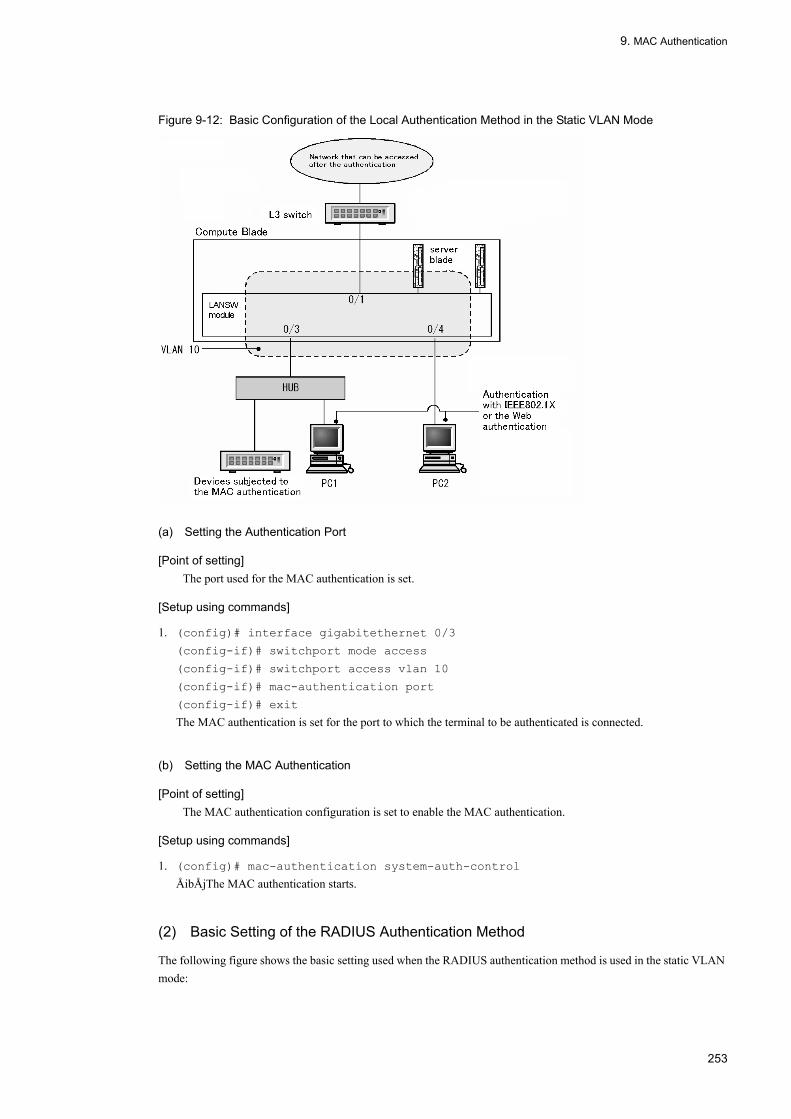
9. MAC Authentication
Figure 9-12: Basic Configuration of the Local Authentication Method in the Static VLAN Mode
(a) Setting the Authentication Port
[Point of setting]The port used for the MAC authentication is set.
[Setup using commands]
1. (config)# interface gigabitethernet 0/3
(config-if)# switchport mode access
(config-if)# switchport access vlan 10
(config-if)# mac-authentication port
(config-if)# exit
The MAC authentication is set for the port to which the terminal to be authenticated is connected.
(b) Setting the MAC Authentication
[Point of setting]The MAC authentication configuration is set to enable the MAC authentication.
[Setup using commands]
1. (config)# mac-authentication system-auth-control
ÅibÅjThe MAC authentication starts.
(2) Basic Setting of the RADIUS Authentication Method
The following figure shows the basic setting used when the RADIUS authentication method is used in the static VLAN mode:
253

9. MAC Authentication
Figure 9-13: Basic Configuration of the RADIUS Authentication Method in the Static VLAN Mode
(a) Setting the Authentication Port
[Point of setting]The port used for the MAC authentication is set.
[Setup using commands]
1. (config)# interface gigabitethernet 0/3
(config-if)# switchport mode access
(config-if)# switchport access vlan 10
(config-if)# mac-authentication port
(config-if)# exit
The MAC authentication is set for the port to which the terminal to be authenticated is connected.
(b) Setting the MAC Authentication
[Point of setting]ÅiaÅjÅibÅjThe MAC authentication configuration is set to enable the MAC authentication.
[Setup using commands]
1. (config)# aaa authentication mac-authentication default group radius
(config)# mac-authentication radius-server host 192.168.10.200 key "macauth"
To use the RADIUS server for the authentication, the IP address and RADIUS key are set.
2. (config)# mac-authentication system-auth-control
The MAC authentication starts.
254

9. MAC Authentication
9.2.3 Dynamic VLAN Mode configuration
(1) Basic Setting of the Local Authentication Method
The following figure shows the basic setting used when the local authentication method is used in the Dynamic VLAN Mode:
Figure 9-14: Basic Configuration of the Local Authentication Method in the Dynamic VLAN Mode
(a) Setting the Authentication Port
[Point of setting]The port used for the MAC authentication is set.
[Setup using commands]
1. (config)# interface range gigabitethernet 0/3-4
(config-if-range)# switchport mode mac-vlan
(config-if-range)# switchport mac vlan 20
(config-if-range)# switchport mac native-vlan 10
(config-if-range)# mac-authentication port
(config-if-range)# exit
The MAC authentication is set for the port to which the terminal to be authenticated is connected.
(b) Setting the MAC Authentication
[Point of setting]The MAC authentication configuration is set to enable the MAC authentication.
[Setup using commands]
1. (config)# mac-authentication system-auth-control
255

9. MAC Authentication
The MAC authentication starts.
(2) Basic Setting of the RADIUS Authentication Method
The following figure shows the basic setting used when the RADIUS authentication method is used in the Dynamic VLAN Mode:
Figure 9-15: Basic Configuration of the RADIUS Authentication Method in the Dynamic VLAN Mode
(a) Setting the Authentication Port
[Point of setting]The port used for the MAC authentication is set.
[Setup using commands]
1. (config)# interface range gigabitethernet 0/3-4
(config-if-range)# switchport mode mac-vlan
(config-if-range)# switchport mac vlan 20
(config-if-range)# switchport mac native-vlan 10
(config-if-range)# mac-authentication port
(config-if-range)# exit
The MAC authentication is set for the port to which the terminal to be authenticated is connected.
(b) Setting the MAC Authentication
[Point of setting]The MAC authentication configuration is set to enable the MAC authentication.
[Setup using commands]
256

9. MAC Authentication
1. (config)# aaa authentication mac-authentication default group radius
(config)# mac-authentication radius-server host 192.168.10.200 key "macauth"
To use the RADIUS server for the authentication, the IP address and RADIUS key are set.
2. (config)# mac-authentication system-auth-control
The MAC authentication starts.
9.2.4 Setting the MAC Authentication ParametersExplained below is the method of setting the parameters that can be set for the MAC authentication.
(1) Setting the Maximum Authentication Time
[Point of setting]Set the time when the authenticated terminal is forcibly released from the authentication.
[Setup using commands]
1. (config)# mac-authentication max-timer 60
Set this time as 60 minutes.
(2) Setting the Number of Authentications in the Static VLAN Mode
[Point of setting]Set the number of MAC addresses that can be authenticated in the static VLAN mode.
[Setup using commands]
1. (config)# mac-authentication static-vlan max-user 20
Set 20 as the number of MAC addresses that can be authenticated in the MAC authentication static VLAN mode.
(3) Setting the RADIUS Server
[Point of setting]Set the RADIUS server used for the RADIUS authentication method.
[Setup using commands]
1. (config)# aaa authentication mac-authentication default group radius
Make the setting so that the authentication is performed with the RADIUS server.
(4) Setting the Accounting
[Point of setting]Make the setting so that the accounting is aggregated.
[Setup using commands]
1. (config)# aaa accounting mac-authentication default start-stop group radius
Make the setting so that the accounting is aggregated for the RADIUS server.
257
9. MAC Authentication
(5) Setting the Output to the syslog Server
[Point of setting]Make the setting in which the authentication result and operation log are output to the syslog server.
[Setup using commands]
1. (config)# mac-authentication logging enable
Make the setting in which the MAC authentication operation log is output to the syslog server.
(6) Setting in Which VLAN ID Is Also Collated at Authentication
[Point of setting]At authentication, make the setting when VLAN ID is collated as well as the MAC address.
[Setup using commands]
1. (config)# mac-authentication vlan-check key "@@VLAN"
VLAN ID is also collated at authentication.An inquiry is made to RADIUS with the RADIUS authentication method, using the string in which the MAC address and VLAN ID are connected with each other with characters "@@VLAN."
(7) Setting the RADIUS Inquiry Password
[Point of setting]Set the password used at collation for RADIUS.
[Setup using commands]
1. (config)# mac-authentication password pakapaka
Set "pakapaka" as the password used at collation for RADIUS.
(8) Setting the Re-Authentication Time Interval After the Authentication Fails
[Point of setting]Set the re-authentication time interval continuing until the next authentication after the authentication failure.
[Setup using commands]
1. (config)# mac-authentication auth-interval-timer 10
Make the setting so that re-authentication occurs 10 minutes after the authentication fails.
(9) Setting the Authentication Access List
[Point of setting]Make the setting so that a specific packet is transferred from the pre-authentication terminal to the outside of this device.
[Setup using commands]
1. (config)# ip access-list extended 100
(config-ext-nacl)# permit udp 0.0.0.0 0.0.0.0 host 255.255.255.255 eq bootps
(config-ext-nacl)# permit udp 0.0.0.0 0.0.0.0 host 192.168.10.100 eq bootps
(config-ext-nacl)# exit
258

9. MAC Authentication
(config)# interface gigabitethernet 0/3
(config-if)# authentication ip access-group 100
(config-if)# exit
Set the IPv4 access list that allows only the DHCP packet to access 192.168.10.100 from the pre-authentication terminal.
(10) Åi10ÅjSetting the Number of Authentication in the Dynamic VLAN Mode
[Point of setting]Set the number of MAC addresses that can be authenticated in the dynamic VLAN mode.
[Setup using commands]
1. (config)# mac-authentication dynamic-vlan max-user 20
Set 20 as the number of MAC addresses that can be authenticated in the MAC authentication dynamic VLAN mode.
(11) Setting Invalidness for the Operation in Which No-Access from the Terminal Is Detected and the Authentication Is Released
[Point of setting]Make the setting so that, in the dynamic VLAN mode, authentication is not released even if no-access from the terminal having the authenticated MAC address continues.
[Setup using commands]
1. (config)# no mac-authentication auto-logout
Make the setting so that, in the dynamic VLAN mode, authentication is not released even if no-access from the terminal having the authenticated MAC address continues.
9.2.5 Method of Exclusion from AuthenticationExplained below is the setting for the exclusion from the MAC authentication.
(1) Setting the Port to Be Excluded from the Static VLAN Mode Authentication
Set the port that is allowed for communication without being authenticated in the static VLAN mode.
[Point of setting]The port excluded from the authentication is not set as the authentication one.
[Setup using commands]
1. (config)# vlan 10
(config-vlan)# state active
(config-vlan)# exit
(config)# interface gigabitethernet 0/4
(config-if)# switchport mode access
(config-if)# switchport access vlan 10
(config-if)# mac-authentication port
(config-if)# exit
(config)# interface gigabitethernet 0/10
(config-if)# switchport mode access
259

9. MAC Authentication
(config-if)# switchport access vlan 10
(config-if)# exit
Port 0/4 for which VLAN ID 10 handled in the static VLAN mode is set as the authentication port. Moreover, make the setting so that port 0/10 is allowed for communication without being authenticated.
(2) Setting the Terminal Excluded from the Static VLAN Mode Authentication
Set the MAC address of the terminal that is allowed for communication without being authenticated in the static VLAN mode, as follows:
[Point of setting]Register the MAC address of the terminal excluded from authentication, in the MAC address table.
[Setup using commands]
1. (config)# vlan 10
(config-vlan)# state active
(config-vlan)# exit
(config)# mac-address-table static 0012.e212.3456 vlan 10 interface
gigabitethernet 0/10
Set the MAC address that is allowed for communication without being authenticated, for port 0/10 of VLAN ID 10.
(3) Setting the Port Excluded from Authentication in the Dynamic VLAN Mode
Set the port that is allowed for communication without being authenticated in the dynamic VLAN mode, as follows:
[Point of setting]Do not set the port excluded from authentication, as the authentication port.
[Setup using commands]
1. (config)# vlan 10
(config-vlan)# state active
(config-vlan)# exit
(config)# interface gigabitethernet 0/4
(config-if)# switchport mode mac-vlan
(config-if)# switchport mac vlan 20
(config-if)# switchport mac native-vlan 10
(config-if)# mac-authentication port
(config-if)# exit
(config)# interface gigabitethernet 0/10
(config-if)# switchport mode access
(config-if)# switchport access vlan 20
(config-if)# exit
Set, as the authentication port, port 0/4 for which MAC VLAN ID 20 handled in the dynamic VLAN mode is set. Make the setting so that port 0/10 is allowed for communication without being authenticated.
(4) Setting the Terminal Excluded from Dynamic VLAN Mode Authentication
Set the MAC address of the terminal that is allowed for communication without being authenticated in the dynamic VLAN mode, as follows:
260

9. MAC Authentication
[Point of setting]Register the MAC address of the terminal excluded from authentication, in MAC VLAN and the MAC address table.
[Setup using commands]
1. (config)# vlan 20 mac-based
(config-vlan)# mac-address 0012.e212.3456
(config-vlan)# exit
(config)# mac-address-table static 0012.e212.3456 vlan 20 interface
gigabitethernet 0/10
Set the MAC address of the terminal that is allowed for communication without being authenticated, for port 0/10 of MAC VLAN ID 20.
261

9. MAC Authentication
9.3 Operation
9.3.1 List of Operation CommandsThe following table lists the MAC authentication operation commands:
Table 9-10: List of Operation Commands
9.3.2 Displaying the MAC Authentication Setting InformationMAC authentication setting information is displayed with the "show mac-authentication" command.
(1) Displaying the Static VLAN Mode Setting Information
Figure 9-16: Displaying the MAC Authentication Setting Information in the Static VLAN Mode
# show mac-authenticationDate 2008/04/10 10:52:49 UTCmac-authentication Information: Authentic-method : RADIUS Accounting-state : disable Syslog-send : enable Authentic-mode : Static-vlan Max-timer : 60 Max-terminal : 1024 Port Count : 2 Auto-logout : - vlan-check : enable Vid-key : %VLAN Port : 0/1 VLAN ID : 5,10,15 access-list-NoÅF 1000 Port : 0/2 VLAN ID : 15-16 access-list-NoÅF 1000
Command Description
show mac-authentication login Displays the MAC address already subjected to the MAC authentication.
show mac-authentication logging Displays the MAC authentication operation log information.
show mac-authentication Displays the MAC authentication configuration.
show mac-authentication statistics Displays statistic information.
clear mac-authentication auth-state mac-address Releases forcibly the authentication of the authenticated terminal.
clear mac-authentication logging Clears the operation log information.
clear mac-authentication statistics Clears the statistic information.
set mac-authentication mac-address Registers the MAC address in the built-in MAC authentication DB.
remove mac-authentication Deletes the MAC address from the built-in MAC authentication DB.
commit mac-authentication Saves the built-in MAC authentication DB in the flash memory.
show mac-authentication mac-address Displays the information registered in the built-in MAC authentication DB.
store mac-authentication Backs up the built-in MAC authentication DB.
load mac-authentication Restores the built-in MAC authentication DB from the backup file.
restart mac-authentication Restarts the MAC authentication program.
dump protocols mac-authentication Collects the MAC authentication dump information.
262

9. MAC Authentication
(2) Displaying the Dynamic VLAN Mode Setting Information
Figure 9-17: Displaying the MAC Authentication Setting Information in the Dynamic VLAN Mode
# show mac-authenticationDate 2008/04/10 10:52:49 UTCmac-authentication Information: Authentic-method : RADIUS Accounting-state : disable Syslog-send : enable Authentic-mode : Dynamic-vlan Max-timer : 60 Max-terminal : 256 Port Count : 2 Auto-logout : enable Port : 0/1 VLAN ID : 1000,1500 access-list-NoÅF 1000 Port : 0/2 VLAN ID : 1005-1006 access-list-NoÅF 1000
9.3.3 Displaying MAC Authentication Statistic InformationThe MAC authentication status and the communication status with RADIUS are displayed with the "show mac-authentication statistics" command.
Figure 9-18: Displaying the MAC Authentication
# show mac-authentication statisticsDate 2007/12/01 11:10:49 UTCmac-authentication Information: Authentication Request Total : 100 Authentication Currect Count : 10 Authentication Error Total : 30RADIUS mac-authentication Information:[RADIUS frames] TxTotal : 130 TxAccReq : 130 TxError : 0 RxTotal : 130 RxAccAccpt: 100 RxAccRejct: 30 RxAccChllg: 0 RxInvalid : 0Account mac-authentication Information:[Account frames] TxTotal : 100 TxAccReq : 100 TxError : 0 RxTotal : 100 RxAccResp : 100 RxInvalid : 0
9.3.4 Displaying the MAC Authentication StatusThe MAC authentication status is displayed with the "show mac-authentication login" command.
Figure 9-19: Displaying the MAC Authentication Status
# show mac-authentication login Date 2007/12/01 10:52:49 UTC Total client counts:2 MAC address port VLAN Login time Limit time 0012.e200.0001 0/1 3 2007/12/01 09:58:04 UTC 00:10:20 0012.e200.0002 0/10 4094 2007/12/01 10:10:23 UTC 00:20:35
9.3.5 Creating the Built-in MAC Authentication DBAfter the MAC authentication system environment setting and configuration setting are complete, the built-in MAC authentication DB is created. The data already registered in the built-in MAC authentication DB is corrected.
263
9. MAC Authentication
(1) Registering the MAC Address
The MAC address and VLAN ID are registered for each MAC address to be authenticated, with the "set mac-authentication mac-adress" command. An example of registering five MAC addresses is given below.
[Setup using commands]# set mac-authentication mac-address 0012.e200.1234 100# set mac-authentication mac-address 0012.e200.5678 100# set mac-authentication mac-address 0012.e200.9abc 100# set mac-authentication mac-address 0012.e200.def0 100# set mac-authentication mac-address 0012.e200.0001 100
(2) Deleting the MAC Address Information
The registered MAC address is deleted.
[Setup using commands]# remove mac-authentication mac-address 0012.e200.1234The MAC address (0012.e200.1234) is deleted.
(3) Reflecting Information in the Built-in MAC Authentication DB
Information registered and deleted with the "set mac-authentication mac-address" and "remove mac-authentication mac-address" commands, respectively, is reflected in the built-in MAC authentication DB with the "commit mac-authentication" command.
[Setup using commands]# commit mac-authentication
9.3.6 Backing up the Built-in MAC Authentication DBThe following shows the method of backing up the built-in MAC authentication DB and the method of restoration from the backup file:
(1) Backing up the Built-in MAC Authentication DB
A backup file (backupfile in the following below) is created from the built-in MAC authentication DB with the "store mac-authentication" command.
[Setup using commands]# store mac-authentication backupfileBackup mac-authentication MAC address data. Are you sure? (y/n): y#
(2) Restoring the Built-in MAC Authentication DB
A built-in MAC authentication DB is created from the backup file (backupflile in the following example) with the "load mac-authentication" command.
[Setup using commands]# load mac-authentication backupfileRestore mac-authentication MAC address data. Are you sure? (y/n): y#
264
9. MAC Authentication
9.3.7 Restoring access to the first RADIUS server after intervention by the dead interval functionality
If the first RADIUS server becomes unresponsive, the dead interval functionality causes the switch to start using the second or later RADIUS server. In this case, you can direct the switch to resume use of the first RADIUS server before the time specified by the authentication radius-server dead-interval configuration command has elapsed, by executing the clear mac-authentication dead-interval-timer command.
Figure 9-20: Restoring access to the first RADIUS server
# clear mac-authentication dead-interval-timer#
265

9. MAC Authentication
266

Part 4 Security
10DHCP SnoopingDHCP snooping is a function that enables to monitor the DHCP packets passing through this device in order to restrict the accesses from unreliable terminals and it can be applied to the IPv4 network.This chapter provides an overview and the operation methods of DHCP snooping.
10.1 Overview
10.2 Configurations
10.3 Operations
267

10. DHCP Snooping
10.1 Overview
10.1.1 OutlineDHCP snooping is a function that enables to monitor the DHCP packets passing through this device in order to restrict the accesses from unreliable terminals. In addition, it can support the terminal filter to restrict the IPv4 packets from unreliable terminals and the dynamic ARP check to discard the invalid ARP packets.
DHCP snooping can be used with the connection between the DHCP server and the DHCP client as shown below:
Figure 10-1: Outline of DHCP snooping
The database to register the terminal information is referred to as "binding Database".
The table below shows the support functions with DHCP snooping.
Table 10-1: Support Functions with DHCP Snooping
Item Description
Monitoring DHCP packets • Monitor the DHCP client to which the DHCP server distributes IP address to manage the terminal information with Binding database.
Registering a terminal with IP address • Register statically the terminal information in binding database.
Storing the binding database • Store the binding database and restore the device when rebooting the LANSW module.
268

10. DHCP Snooping
10.1.2 Monitoring DHCP Packets
(1) Port types
DHCP snooping enables to monitor the DHCP packets in the following categories:
• trust port
The port to connect the reliable terminals such as the DHCP server and the branch server is referred to as "trust port".
• untrust port
The port to connect the unreliable terminals such as DHCP client is referred to as "untrust port".
The DHCP server cannot be connected.
The figure below shows the port types.
Figure 10-2: The port types
Checking DHCP packets • Suppress IP address distribution from unreliable DHCP server
• Suppress IP address release from unreliable DHCP client
• Suppress fraud in MAC address
• Suppress fraud in Option 82
Restricting receive rates for DHCP packets • Discard DHCP packets that exceeds the specified receive rates.
Terminal filter • Suppress IPv4 packets relay from unreliable terminals.
Checking ARP packets • Suppress ARP packets relay from unreliable terminals.
• Suppress fraud in MAC addresses and IP addresses.
Restricting receive rates for ARP packets • Discard ARP packets that exceeds the specified receive rates.
Item Description
269

10. DHCP Snooping
All the ports are specified as untrust ports by default when enabling DHCP snooping by configuration command "ip dhcp snooping". The port connected to the DHCP server should be set as a trust port. The trust port can be set using configuration command "ip dhcp snooping trust".
In addition, the VLAN specified by configuration command "ip dhcp snooping vlan" are to be monitored by DHCP snooping.
(2) Learning of the terminal information
The figure below shows the operation summary of the learning of the terminal information.
Figure 10-3: The operation summary of the learning of the terminal information
The trust port allows to monitor the packets received from the DHCP server and to register the terminal information in the binding database when the IP address was distributed.
The untrust port allows to monitor the packets received from the DHCP client and to remove the terminal information from the binding database when the release request of the IP address was accepted.
The registration of the binding database has the following two types:
• Dynamic registration
It can be registered when an IP address was distributed by a DHCP server.
Usually, the terminal information can be registered by dynamic registration.
• Static registration
It can be registered by configuration command "ip source binding". The static registration is used to connect a branch server with a static IP address at the untrust port. The static registration of the terminal information in the binding database allows the communication.
The figure below shows the terminal information to register in the binding database.
Table 10-2: Terminal Information to Registered in Binding Database
Item Dynamic registration Static registration
MAC addresses of terminals MAC addresses of DHCP clients MAC addresses of terminals with static IP addresses
270

10. DHCP Snooping
(3) Storing binding database
The setting of the configuration enables the storage of the binding database and the recovery of it when rebooting the device.
(a) Operating conditions for binding database storage
The binding database storage requires the setup of configuration command "ip dhcp snooping database url".
The storage can actually start at the expiration of the latency time to write specified by the configuration.
(b) Storage at the expiration of the latency time to write
The latency time to write is defined as the latency starting from the trigger for storage until being written when the binding database is stored. The trigger for storage, which is either of the following, allows the timer to start , and the binding database can be stored in the specified storage location at the expiration of the timer.
• When the dynamic binding database is registered, updated, or removed• When setting configuration command "ip dhcp snooping database url" (including changes in storage locations)• When executing operation command "clear ip dhcp snooping binding"
The latency time to write can be set by the configuration command "ip dhcp snooping database write-delay".
When these triggers for storage allow the timer to start, the timer cannot be stopped until the expiration of the timer. During this period, even if the binding database is registered, updated, or removed, the timer could not be restarted.
The figure below shows the correlation between the triggers for storage and the latency time to write. In this figure, the storage is triggered by the registration in the binding database.
IP addresses of terminals IP addresses distributed by DHCP servers IP addresses of terminals with static IP addresses
Enabled for the following ranges• 1.0.0.0 to 126.255.255.255
• 128.0.0.0 to 223.255.255.255
VLAN where terminals belong VLAN IDs that contain ports or channel groups to connect the terminals
Port IDs to connect the terminals
Port numbers and channel group numbers to connect the terminals
Aging time. Time period until the entries are removed with aging.Apply the lease time for the IP addresses distributed by DHCP servers.
Aging is disabled.
Item Dynamic registration Static registration
271

10. DHCP Snooping
Figure 10-4: The correlation between the triggers for storage and the latency time to write
(c) Storage locations of binding database
Either a built-in flash memory or MC can be selected as a storage location. The storage location can be set by the configuration command "ip dhcp snooping database url".
The target data to be stored are all the entries at the time of writing. It is updated at the next writing.
(d) Recovery of stored binding database
The stored binding database can be restored when rebooting the device. Any of the following conditions need to be met to restore it when rebooting the device.
• The storage locations have been set by configuration command "ip dhcp snooping database url".• When a MC is specified as the storage location, a MC for the stored file has been inserted.
(4) Checking DHCP packets
The figure below shows the operation summary for checking DHCP packets.
272

10. DHCP Snooping
Figure 10-5: Operation Summary for Checking DHCP Packets
DHCP packets can be monitored for the terminals connected to the untrust ports, and then the following accesses can be removed.
• Suppress IP address distribution from unreliable DHCP serversWhen untrust ports have received the DHCP packets from unreliable DHCP servers, the corresponding unreliable DHCP packets can be discarded. This operation enables to suppress the IP address distribution from unreliable DHCP clients.
• Suppress IP address release from unreliable DHCP clientsWhen untrust ports have received the IP address release requests from the terminals without the binding database registered, the corresponding DHCP packets can be discarded. This operation enables to suppress the IP address release from the terminals where the IP addresses are not distributed from DHCP servers.Additionally, in the same way, when also received the notification of IP address redundancy detection, lease time update, and option information request, the corresponding DHCP packets can be discarded. This operation enables to suppress the invalid IP address release, the IP address acquisition, and the option acquisition from unreliable DHCP clients.
• Suppress fraud in MAC addressesIf the source MAC address (Source MAC Address) of a DHCP packet received by an untrust port is not consistent with the client hardware address within the DHCP packets, the corresponding DHCP packets can be discarded. This operation enables to suppress the fraud in MAC addresses.
• Suppress fraud in Option 82If the Option 82 is given to a DHCP packet received by an untrust port, the corresponding DHCP packets can be discarded. This operation enables to suppress the fraud in Option 82.
10.1.3 Restricting Receive rates for DHCP PacketsWhen enabling DHCP snooping, this function allows to monitor the received DHCP packets to discard the DHCP packets that exceeds the specified receive rates.
The receive rates can be set by the configuration command “ip dhcp snooping limit rate”. If this command has not been set, the receive rates cannot be restricted.
The DHCP packets that exceeds the specified receive rates are discarded to capture the operation log information.
273

10. DHCP Snooping
However, Trap cannot be issued. The operation log information can be verified by the operation command "show ip dhcp snooping logging".
(1) Capture triggers for operation log information
When the operation log information exceeds the receive rate specified by the configuration command, an "excess detection" event can be captured.
The event cannot be captured for thirty seconds after capturing "excess detection" event, even if the packets are discarded by exceeding the receive rates.
The figure below shows the capture triggers for the operation log information of receive rates for the DHCP packets.
Figure 10-6: Capture triggers for the operation log information of receive rates for the DHCP packets.
10.1.4 Terminal Filtering
(1) Outline
The terminal filtering is a function that enables to monitor the IPv4 packets passing through this device in order to restrict the accesses from unreliable terminals.
The figure below shows the operation summary for the terminal filtering.
274

10. DHCP Snooping
Figure 10-7: Operation Summary for Terminal Filtering
The terminal filtering can be set for each port using configuration command "ip verify source".
The corresponding mode (layer3-dhcp-1) for the terminal filtering needs to be set in the flow detection mode on the receiving side before using the terminal filtering.
(2) IPv4 packet inspection
When the IPv4 packets have been received on untrust ports, the consistency with the binding database are checked, and consequently the corresponding IPv4 packets can be discarded on the terminals where the binding database is not registered.
The table below shows the targets to be checked with the terminal filtering.
Table 10-3: Targets to be checked with the terminal filtering
Legend: Y: Checked, --: Not checked
10.1.5 Dynamic ARP Inspection
(1) Outline
The dynamic ARP inspection is a function that enables to monitor ARP packets passing through this device in order to
Filtering to be performed
IPv4 packet
Receiving interface Ethernet header IP header
Port VLAN ID Source MAC address
Source IP address
Check source MAC addresses only
Y Y Y --
Check source IP addresses only
Y Y -- Y
Check source MAC addresses and source IP addresses
Y Y Y Y
275

10. DHCP Snooping
restrict the ARP packet accesses from unreliable terminals.
The figure below shows the operation summary for the dynamic ARP inspection.
Figure 10-8: Operation summary for the dynamic ARP inspection
(2) Port types
The dynamic ARP inspection enables to monitor the ARP packets in the following categories of the ports in the same way as DHCP snooping:
• trust portThe port to connect the reliable terminals, such as the DHCP server and the branch server, is referred to as "trust port".The ARP packets received by the trust port cannot be monitored.
• untrust portThe port to connect the unreliable terminals such as DHCP client is referred to as "untrust port".The DHCP server cannot be connected.
The figure below shows the port types.
276

10. DHCP Snooping
Figure 10-9: Port types
All the ports are specified as untrust ports by default when enabling DHCP snooping by configuration command "ip dhcp snooping". The port to connect the DHCP server should be set as a trust port. The trust port can be set using configuration command "ip arp inspection trust".
In addition, the VLAN specified by the configuration command "ip arp inspection vlan" is targeted for monitoring with the dynamic ARP inspection.
For usual operation, it is recommended that the port specified by the configuration command "ip dhcp snooping trust" is consistent with the one specified by "ip arp inspection trust".
(3) Basic inspection of ARP packets
When the ARP packets have been received on untrust ports, the consistency with the binding database are checked, and consequently the corresponding ARP packets can be discarded on the terminals where the binding database is not registered.
The table below shows the targets to be checked with the basic inspection.
Table 10-4: Basic inspection Items
Legend: Y: Checked, --: Not checked
(4) Option for checking ARP packets
This enables to check the data consistency of the ARP packets received by untrust ports.
ARP type Receiving interface ARP packet
Port VLAN ID Ethernet header ARP header
Destination MAC
address
Source MAC
address
Source MAC
address
Source IP
address
Destination MAC address
Destination IP
address
Request Y Y -- -- Y Y -- --
Reply Y Y -- -- Y Y -- --
277

10. DHCP Snooping
The option checking can be set by configuration command "ip arp inspection validate".
(a) Checking source MAC address (src-mac checking)
This enables to check that the source MAC address (Source MAC) included in the Layer2 header and the sender MAC address (Sender MAC Address) included in the ARP header are identical.
This is executed both for ARP Request and ARP Reply.
The table below shows the targets to be checked with the source MAC address checking.
Table 10-5: Source MAC address inspection items
Legend: Y: Checked, --: Not checked
(b) Checking destination MAC address (dst-mac checking)
This enables to check that the destination MAC address (Destination MAC) included in the Layer2 header and the target MAC address (Target MAC Address) included in the ARP header are identical.
This is executed only for ARP Reply.
The table below shows the targets to be checked by the destination MAC address checking.
Table 10-6: Destination MAC address inspection items
Legend: Y: Checked, --: Not checked
(c) Checking IP address (ip checking)
This enables to check that the target IP address (Target IP Address) included in the ARP header are covered by the following ranges:
• 1.0.0.0 to 126.255.255.255• 128.0.0.0 to 223.255.255.255
This is executed only for ARP Reply.
ARP type Receiving interface ARP packet
Port VLAN ID Ethernet header ARP header
Destination MAC address
Source MAC
address
Source MAC
address
Source IP address
Destination MAC address
Destination IP
address
Request -- -- -- Y Y -- -- --
Reply -- -- -- Y Y -- -- --
ARP type Receiving interface ARP packet
Port VLAN ID Ethernet header ARP header
Destination MAC address
Source MAC
address
Source MAC
address
Source IP
address
Destination MAC address
Destination IP
address
Request -- -- -- -- -- -- -- --
Reply -- -- Y -- -- -- Y --
278

10. DHCP Snooping
The table below shows the targets to be checked with the IP address checking.
Table 10-7: IP address inspection items
Legend: Y: Checked, --: Not checked
10.1.6 Restricting Receive rates for ARP PacketsWhen enabling the dynamic ARP inspection, this function allows to monitor the received ARP packets to discard the ARP packets that exceeds the specified receive rates.
The receive rates can be set by the configuration command "ip arp inspection limit rate". If this command has not been set, the receive rates cannot be restricted.
All the ARP packets received by this device are targeted for the restrictions on the receive rates for the ARP packets.
The ARP packets that exceeds the specified receive rates are discarded to capture the operation log information. However, Trap cannot be issued. The operation log information can be verified by the operation command "show ip dhcp snooping logging".
(1) Capture triggers for operation log information
The capture triggers for the operation log information are defined in the same way as restrictions on the receive rates for the DHCP packets.
For the capture triggers, see “10.1.3 Restricting Receive rates for DHCP Packets(1) Capture triggers for operation log information".
10.1.7 Notes on Using DHCP Snooping
(1) Coexistence of Layer 2 switch functions
For additional information , see "15.3 Coexistence of Layer 2 Switch Function and Other Functions" in Configuration Settings, Vol. 1.
(2) Coexistence of Layer 2 Authentication
(a) Coexistence of Web Authentication
For additional information , see ”5.2.1 Coexistence of Layer 2 Authentication and Other Functions”.
(b) Notes on setting IPv4 access list
When DHCP snooping coexists with the IPv4 access list dedicated to the authentication, even if either the protocol name bootps or bootpc is specified in the filter conditions of the authentication-dedicated IPv4 access list, both packets of bootps and bootpc can be transparently transmitted, regardless of the other filter conditions.
ARP type Receiving interface ARP packet
Port VLAN ID Ethernet header ARP header
Destination MAC address
Source MAC
address
Source MAC
address
Source IP
address
Destination MAC address
Destination IP
address
Request -- -- -- -- -- -- -- --
Reply -- -- -- -- -- -- -- Y
279

10. DHCP Snooping
(c) Coexistence of port mirroring
When enabling DHCP snooping, all the DHCP packets transmitted by this device cannot be mirrored. Moreover, when also enabling the dynamic ARP inspection, all the ARP packets transmitted by this device cannot also be mirrored.
(3) Storage and recovery of binding database•When the configuration command "ip dhcp snooping database url" has not been set (default status), the binding database cannot be stored. When stopping and rebooting the device, the registered binding database is deleted, and thus the transmissions from the DHCP clients are disabled. If unable to transmit, the IP addresses should be released and updated on the DHCP client sides. For example, for Windows, Ågipconfig /renewÅh should be executed after executing "ipconfig /release" in the command prompt.This execution enables to re-register the terminal information in the binding database, and thus the transmissions from the DHCP clients are enabled.
•Among restored entries, the entries at the expiration of the lease-time of the DHCP server cannot be restored. After the storage of the binding database, when the time setting is changed before stopping and rebooting the device, the binding database may not be restored properly after rebooting the device.
•The entries statically registered by the configuration command "ip source binding" can be restored according to the startup configuration command.
•When a MC is specified as the storage location for the binding database, the MC should not be removed until prompt appears in the window after rebooting the device.
(4) Restricting receive rates for DHCP packets•When the restriction on the receive rates for the DHCP packets coexists with the restriction on the receive rates for the ARP packets, the monitoring can be performed with the total rates of the receive rates for the DHCP packets and that for the ARP packets.
(5) Dynamic ARP inspection•The dynamic ARP inspection requires the set up of the following configurations to generate the binding database.
- ip dhcp snooping- ip dhcp snooping vlan
•The entries statically registered in the binding database by the configuration command "ip source binding" are also targeted for the dynamic ARP inspection.
(6) Restricting receive rates for ARP packets•When the restriction on the receive rates for ARP packets coexists with the restriction on the receive rates for DHCP packets, the monitoring can be performed with the total rates of the receive rates for the ARP packets and that for the DHCP packets.
280
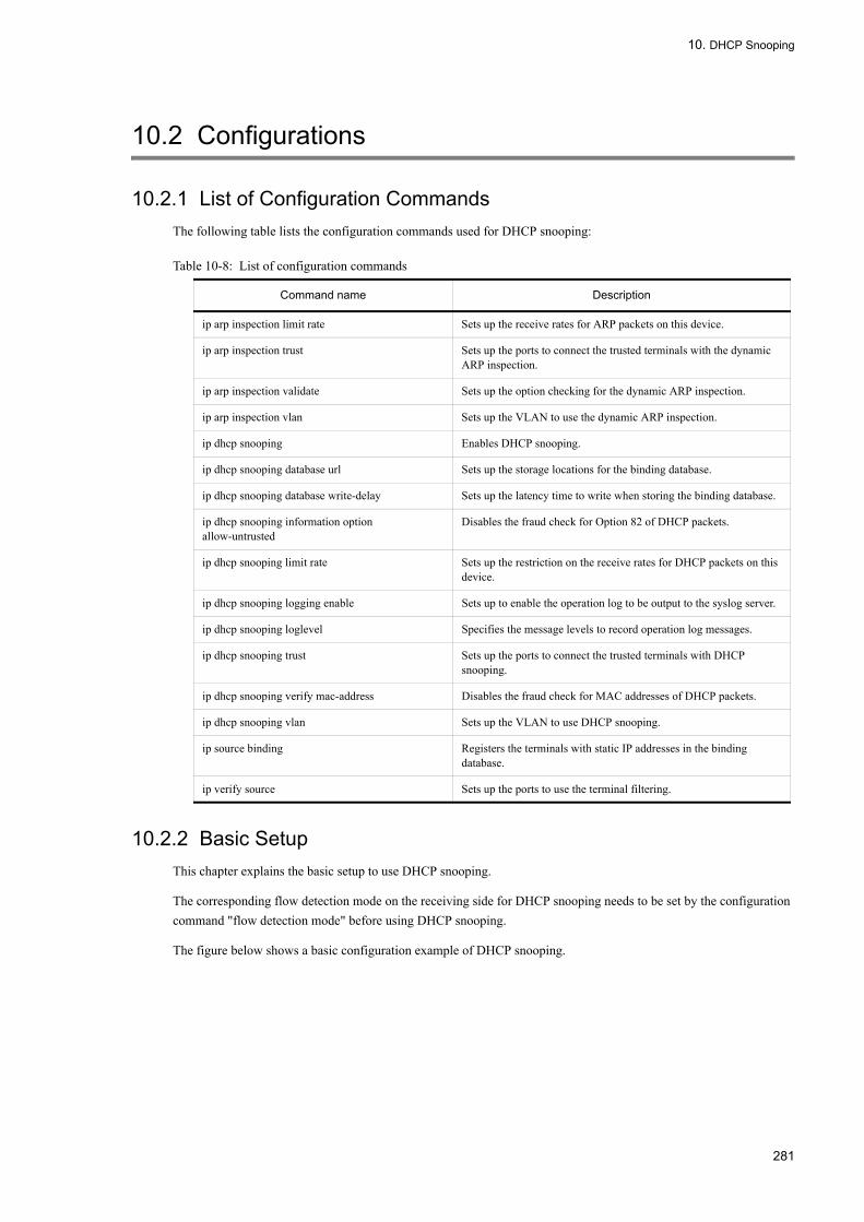
10. DHCP Snooping
10.2 Configurations
10.2.1 List of Configuration CommandsThe following table lists the configuration commands used for DHCP snooping:
Table 10-8: List of configuration commands
10.2.2 Basic SetupThis chapter explains the basic setup to use DHCP snooping.
The corresponding flow detection mode on the receiving side for DHCP snooping needs to be set by the configuration command "flow detection mode" before using DHCP snooping.
The figure below shows a basic configuration example of DHCP snooping.
Command name Description
ip arp inspection limit rate Sets up the receive rates for ARP packets on this device.
ip arp inspection trust Sets up the ports to connect the trusted terminals with the dynamic ARP inspection.
ip arp inspection validate Sets up the option checking for the dynamic ARP inspection.
ip arp inspection vlan Sets up the VLAN to use the dynamic ARP inspection.
ip dhcp snooping Enables DHCP snooping.
ip dhcp snooping database url Sets up the storage locations for the binding database.
ip dhcp snooping database write-delay Sets up the latency time to write when storing the binding database.
ip dhcp snooping information option allow-untrusted
Disables the fraud check for Option 82 of DHCP packets.
ip dhcp snooping limit rate Sets up the restriction on the receive rates for DHCP packets on this device.
ip dhcp snooping logging enable Sets up to enable the operation log to be output to the syslog server.
ip dhcp snooping loglevel Specifies the message levels to record operation log messages.
ip dhcp snooping trust Sets up the ports to connect the trusted terminals with DHCP snooping.
ip dhcp snooping verify mac-address Disables the fraud check for MAC addresses of DHCP packets.
ip dhcp snooping vlan Sets up the VLAN to use DHCP snooping.
ip source binding Registers the terminals with static IP addresses in the binding database.
ip verify source Sets up the ports to use the terminal filtering.
281

10. DHCP Snooping
Figure 10-10: Port types
(1) Enabled setting for DHCP snooping
[Point of setting]
Enable DHCP snooping as a device, and set the VLAN to enable DHCP snooping.
[Setup using commands]
1. (config)# ip dhcp snooping
Enables DHCP snooping as a device.2. (config)# vlan 2
(config-vlan)# exit
(config)# ip dhcp snooping vlan 2
Enables DHCP snooping on VLAN ID 2. The DHCP snooping cannot be enabled on the VLAN where this command is not specified.
3. (config)# interface gigabitethernet 0/1
(config-if)# switchport mode access
(config-if)# switchport access vlan 2
(config-if)# exit
Specifies the port 0/1 as an access port, and specifies the VLAN ID 2 as the VLAN that the port 0/1 belongs to.
(2) Setting trust port for DHCP snooping
[Point of setting]
Set the port to connect the DHCP server (the port to connect the Layer 3 switch /router in “Figure 10-10 Basic Configuration Example of DHCP Snooping” ) as a trust port.
[Setup using commands]
1. (config)# interface gigabitethernet 0/5
(config-if)# ip dhcp snooping trust
(config-if)# switchport mode access
282

10. DHCP Snooping
(config-if)# switchport access vlan 2
(config-if)# exit
Specifies the port 0/5 as a trust port. Any other ports are specified as untrust ports.Specifies the port 0/5 as an access port, and specifies the VLAN ID 2 as the VLAN that the port 0/5 belongs to.
2. (config)# interface gigabitethernet 0/1
(config-if)# switchport mode access
(config-if)# switchport access vlan 2
(config-if)# exit
Specifies the port 0/1 as an access port, and specifies the VLAN ID 2 as the VLAN that the port 0/1 belongs to.
(3) Setting storage location for binding database
(a) When storing in a built-in flash memory
[Point of setting]
Specify a built-in flash memory as a storage location for the binding database.
[Setup using commands]
1. (config)# ip dhcp snooping database url flash
Specifies a built-in flash memory as a storage location
(b) When storing in a MC
[Point of setting]
Specify a MC as a storage location for the binding database. The file name to be stored can be specified for a MC.
[Setup using commands]
1. (config)# ip dhcp snooping database url mc dhcpsn-db
Specifies a MC as a storage location, and Ågdhcpsn-dbÅh as a file name to be stored.
[Note]
When a MC is specified as the storage location, the MC should be installed in the memory card slot on this device.
The MC produced by Arakusara is recommended.
(4) Setting latency time to write in storage locations for binding database.
[Point of setting]
Set the latency time to write in the storage locations for the binding database.
[Setup using commands]
1. (config)# ip dhcp snooping database write-delay 3600
Either of the following triggers the storage and allows to set the time period before starting the storage to 3600 seconds.
•When the dynamic binding database is registered, updated, and removed
•When setting configuration command "ip dhcp snooping database url" (including changes in storage locations)
•When executing operation command "clear ip dhcp snooping binding"
[Note]
The time specified by this command takes effect the operation from the next trigger for storage.
283

10. DHCP Snooping
10.2.3 Restricting Receive Rates for DHCP PacketsThis chapter explains the setup for using the restrictions on the receive rates for the DHCP packets.
[Point of setting]
Set the receive rates for the DHCP packets received from the terminal by this device.
[Setup using commands]
1. (config)# ip dhcp snooping limit rate 50
Sets the receive rate for this device to 50 packets per second.
10.2.4 Terminal FilteringThis chapter explains the setup for using the terminal filtering.
[Point of setting]
Set the terminal filtering for the ports to connect the DHCP clients.
[Setup using commands]
1. (config)# interface gigabitethernet 0/1
(config-if)# ip verify source port-security
(config-if)# exit
Sets the terminal filtering for the port 0/1 to use the source IP addresses and the source MAC addresses as the terminal filtering conditions.
[Note]
The terminal filtering is disabled even if the configuration command “ip verify source” are set for the trust port.
Please note that when enabling DHCP snooping, the terminal filtering can be enabled on VLAN without configuration command "ip dhcp snooping vlan" specified.
10.2.5 Dynamic ARP InspectionThis chapter explains the setup for using the dynamic ARP inspection.
(1) Basic setup
[Point of setting]
Set the VLAN to enable the basic inspection for the dynamic ARP inspection.
[Setup using commands]
1. (config)# ip arp inspection vlan 2
Sets the VLAN ID 2 to be checked with the dynamic ARP inspection. The dynamic ARP inspection cannot be enabled on the VLAN without this command specified.
[Note]
•Specify the VLAN ID to be set by the configuration command "ip dhcp snooping vlan".
•If this command is set, the binding database entries registered by the configuration command "ip source binding" are also targeted for the dynamic ARP inspection.
•If the configuration command "ip arp inspection trust" is set for the ports on the VLAN specified by this command,
284
10. DHCP Snooping
the ports are not targeted for the dynamic ARP inspection.
(2) Setting trust port
[Point of setting]
Set the port for connection to the DHCP server as a trust port.
[Setup using commands]
1. (config)# interface gigabitethernet 0/5
(config-if)# ip arp inspection trust
(config-if)# exit
Specifies the port 0/5 as a trust port. Any other ports are specified as untrust ports.
[Note]
If the ports set by this command belong to the VLAN to be checked with the dynamic ARP inspection, the ports are not targeted for the dynamic ARP inspection.
(3) Setting Option checking
[Point of setting]
Enable the source MAC address checking (src-mac checking) as an option checking for the dynamic ARP inspection on this device.
[Setup using commands]
1. (config)# ip arp inspection validate src-mac
Enables the source MAC address checking (src-mac checking) as an option checking.
10.2.6 Restricting Receive Rates for ARP PacketsThis chapter explains the setup for using the restrictions on the receive rates for the ARP packets.
[Point of setting]
Set the receive rates for the ARP packets received by this device.
[Setup using commands]
1. (config)# ip arp inspection limit rate 100
Sets the receive rates for this device to 100 packets per second.
10.2.7 Connecting Terminal with Static IP AddressThis chapter explains the setup for connecting the terminal with the static IP address.
The figure below shows the configuration example for connecting the terminal with the static IP address.
285

10. DHCP Snooping
Figure 10-11: The configuration example for connecting the terminal with the static IP address
The setup for DHCP snooping is defined in the same way as "10.2.2 Basic Setup". This example requires the static registration of the terminal with the static IP address in the binding database, since the terminal with the static IP address is connected to the untrust port.
[Point of setting]
The information on the terminal with the static IP address is statically registered in the binding database.
[Setup using commands]
1. (config)# ip source binding 0012.e2ff.2222 vlan 2 192.168.100.22 interface
MAC address of the terminal, VLAN (VLAN ID) that the terminal belongs to, IP address of the terminal, and the number of the port for connecting the terminal should be set in the binding database.
10.2.8 Connecting DHCP Relay under This DeviceWhen the DHCP relay is connected under this device, make the setting to allow this device to relay packets.
The figure below shows the configuration example for connecting the DHCP relay under this device.
286

10. DHCP Snooping
Figure 10-12: The configuration example for connecting the terminal with the static IP address
The setup for DHCP snooping on this device is defined in the same way as "10.2.2 Basic Setup", "10.2.4 Terminal Filtering" , and "10.2.5 Dynamic ARP Inspection".
In this configuration example, the DHCP packets and IPv4 packets cannot be relayed from DHCP clients. Moreover, the ARP packets cannot be relayed from Layer 3 switches/routers.
To relay the packets, it requires the setting to allow this device to relay the DHCP packets, the IPv4 packets, and the ARP packets.
(1) Setting to allow to relay DHCP packets
[Point of setting]
Disable the fraud check for MAC addresses of the DHCP packets since the source MAC addresses of the packets relayed from DHCP client have been rewritten by Layer 3 switch/router (DHCP relay).
[Setup using commands]
1. (config)# no ip dhcp snooping verify mac-address
Sets to disable the fraud check for MAC addresses of the untrust port.
[Note]
The DHCP relay cannot be connected to the untrust port since the fraud check for MAC addresses is enabled unless this command is set.
(2) Setting to allow to relay IPv4 packets
[Point of setting]
Set the only source IP address as the terminal filtering condition since the source MAC addresses of the packets relayed from DHCP client have been rewritten by Layer 3 switch/router (DHCP relay).
[Setup using commands]
287
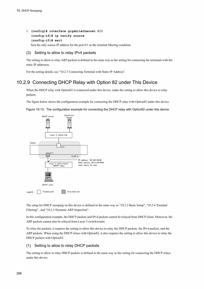
10. DHCP Snooping
1. (config)# interface gigabitethernet 0/1
(config-if)# ip verify source
(config-if)# exit
Sets the only source IP address for the port 0/1 as the terminal filtering condition.
(3) Setting to allow to relay IPv4 packets
The setting to allow to relay ARP packets is defined in the same way as the setting for connecting the terminals with the static IP addresses.
For the setting details, see "10.2.7 Connecting Terminal with Static IP Address".
10.2.9 Connecting DHCP Relay with Option 82 under This DeviceWhen the DHCP relay with Option82 is connected under this device, make the setting to allow this device to relay packets.
The figure below shows the configuration example for connecting the DHCP relay with Option82 under this device.
Figure 10-13: The configuration example for connecting the DHCP relay with Option82 under this device
The setup for DHCP snooping on this device is defined in the same way as "10.2.2 Basic Setup", "10.2.4 Terminal Filtering" , and "10.2.5 Dynamic ARP Inspection".
In this configuration example, the DHCP packets and IPv4 packets cannot be relayed from DHCP client. Moreover, the ARP packets cannot also be relayed from Layer 3 switch/router.
To relay the packets, it requires the setting to allow this device to relay the DHCP packets, the IPv4 packets, and the ARP packets. When using the DHCP relays with Option82, it also requires the setting to allow this device to relay the DHCP packets with Option82.
(1) Setting to allow to relay DHCP packets
The setting to allow to relay DHCP packets is defined in the same way as the setting for connecting the DHCP relays under this device.
288

10. DHCP Snooping
For the setting details, see "10.2.8 Connecting DHCP Relay under This Device (1) Setting to allow to relay DHCP packets".
(2) Setting to allow to relay IPv4 packets
The setting to allow to relay IPv4 packets is defined in the same way as the setting for connecting the DHCP relays under this device.
For the setting details, see " 10.2.8 Connecting DHCP Relay under This Device (2) Setting to allow to relay IPv4 packets".
(3) Setting to allow to relay ARP packets
The setting to allow to relay ARP packets is defined in the same way as the setting for connecting the terminals with the static IP addresses.
For the setting details, see "10.2.7 Connecting Terminal with Static IP Address".
(4) Setting to allow to relay DHCP packets with Option82
[Point of setting]
Disable the fraud check for Option82 of the DHCP packets.
[Setup using commands]
1. (config)# ip dhcp snooping information option allow-untrusted
Sets to disable the fraud check for Option82 of the untrust port.
10.2.10 Outputs to Syslog Server[Point of setting]
Enable the operation log to be output to the syslog server.
[Setup using commands]
1. (config)# ip dhcp snooping logging enable
Enables the operation log to be output to the syslog server.2. (config)# logging event-kind dsn
Sets DHCP snooping for each event type for the log information to be sent to the syslog server.
289

10. DHCP Snooping
10.3 Operations
10.3.1 List of Operation CommandsThe following table lists the operation commands used for DHCP snooping:
Table 10-9: List of Operation Commands
10.3.2 Checking DHCP Snooping Binding DatabaseThe binding database information can be displayed using "show ip dhcp snooping binding" command. MAC addresses of the terminals, IP addresses, and aging time for binding database are displayed.
The figure below shows the execution results of "show ip dhcp snooping binding" command:
Figure 10-14: Result of executing show ip dhcp snooping binding
> show ip dhcp snooping bindingDate 20XX/04/20 12:00:00 UTCAgent URL: flashLast succeeded time: 20XX/04/20 11:50:00 UTCTotal Bindings Used/Max : 5/ 1500Total Source guard Used/Max: 2/ 1500 Bindings: 5MAC Address IP Address Expire(min) Type VLAN Port0012.e287.0001 192.168.0.201 - static* 1 0/10012.e287.0002 192.168.0.204 1439 dynamic 2 0/40012.e287.0003 192.168.0.203 - static 3 0/30012.e287.0004 192.168.0.202 3666 dynamic 4 ChGr:20012.e2be.b0fb 192.168.100.11 59 dynamic* 12 0/11>
10.3.3 Checking DHCP Snooping Statistical InformationThe statistical information on DHCP snooping can be displayed using "show ip dhcp snooping statistics" command. The total number of DHCP packets received on untrust ports, the number of DHCP packets received for each interface, and the number of filtered DHCP packets are displayed.
The figure below shows the execution results of "show ip dhcp snooping statistics" command:
Command name Description
show ip dhcp snooping binding Displays the binding database information.
clear ip dhcp snooping binding Clears the binding database information.
show ip dhcp snooping statistics Displays the statistical information.
clear ip dhcp snooping statistics Clears the statistical information.
show ip arp inspection statistics Displays the statistical information on the dynamic ARP inspection.
clear ip arp inspection statistics Clears the statistical information on the dynamic ARP inspection.
show ip dhcp snooping logging Displays the log messages captured by the program.
clear ip dhcp snooping logging Clears the log messages captured by the program.
restart dhcp snooping Restarts the program.
dump protocols dhcp snooping The logs and internal information captured by the program can be output to the files.
290
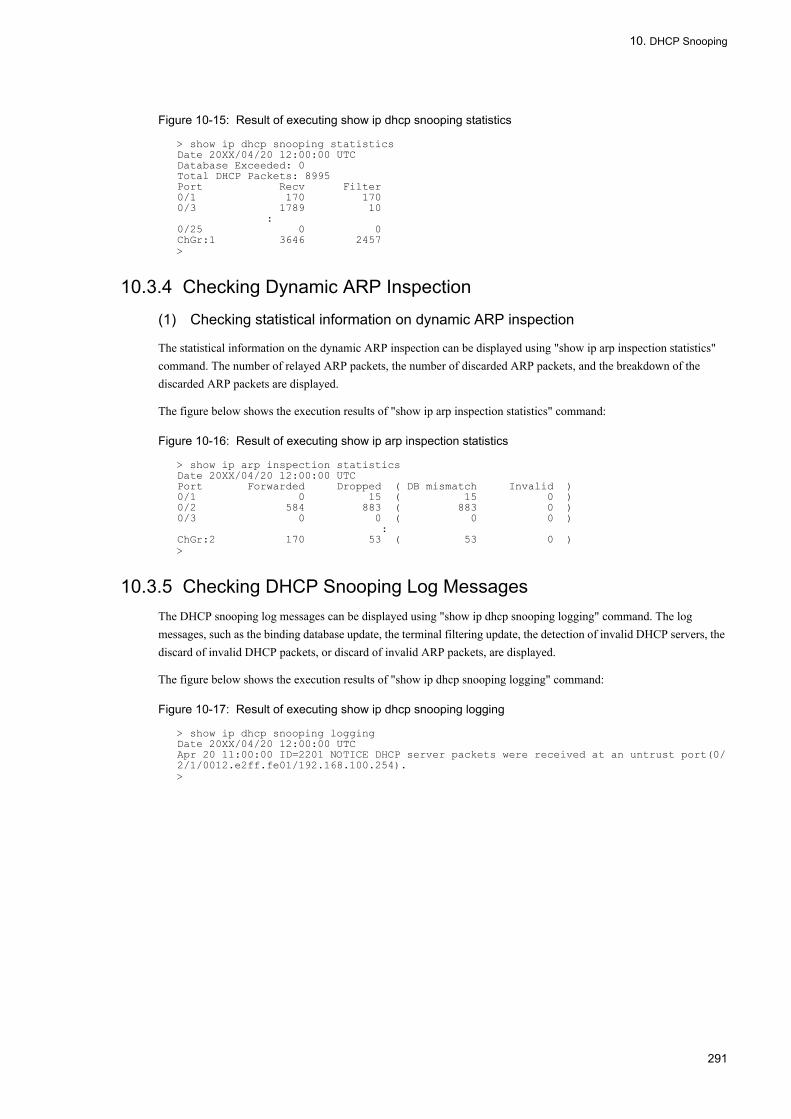
10. DHCP Snooping
Figure 10-15: Result of executing show ip dhcp snooping statistics
> show ip dhcp snooping statisticsDate 20XX/04/20 12:00:00 UTCDatabase Exceeded: 0Total DHCP Packets: 8995Port Recv Filter0/1 170 1700/3 1789 10 :0/25 0 0ChGr:1 3646 2457>
10.3.4 Checking Dynamic ARP Inspection
(1) Checking statistical information on dynamic ARP inspection
The statistical information on the dynamic ARP inspection can be displayed using "show ip arp inspection statistics" command. The number of relayed ARP packets, the number of discarded ARP packets, and the breakdown of the discarded ARP packets are displayed.
The figure below shows the execution results of "show ip arp inspection statistics" command:
Figure 10-16: Result of executing show ip arp inspection statistics
> show ip arp inspection statisticsDate 20XX/04/20 12:00:00 UTCPort Forwarded Dropped ( DB mismatch Invalid )0/1 0 15 ( 15 0 )0/2 584 883 ( 883 0 )0/3 0 0 ( 0 0 ) :ChGr:2 170 53 ( 53 0 )>
10.3.5 Checking DHCP Snooping Log MessagesThe DHCP snooping log messages can be displayed using "show ip dhcp snooping logging" command. The log messages, such as the binding database update, the terminal filtering update, the detection of invalid DHCP servers, the discard of invalid DHCP packets, or discard of invalid ARP packets, are displayed.
The figure below shows the execution results of "show ip dhcp snooping logging" command:
Figure 10-17: Result of executing show ip dhcp snooping logging
> show ip dhcp snooping loggingDate 20XX/04/20 12:00:00 UTCApr 20 11:00:00 ID=2201 NOTICE DHCP server packets were received at an untrust port(0/2/1/0012.e2ff.fe01/192.168.100.254).>
291

10. DHCP Snooping
292

Part 5 High Reliability Functions Based on Redundant Configuration
11General Description of GSRPGSRP provides redundancy for the LANSW module in layer 2 and layer 3. This chapter outlines GSRP.
11.1 GSRP Overview
11.2 GSRP Mechanism
11.3 GSRP Operation Overview
11.4 Layer 3 Redundancy Switchover Function
11.5 GSRP Network Configuration
11.6 Notes on Using GSRP
293

11. General Description of GSRP
11.1 GSRP Overview
11.1.1 Outline of GSRPGSRP (Gigabit Switch Redundancy Protocol) provides redundancy for the switch to secure a communication route via an alternative switch on the same network in the event of a switch failure.
The LANSW module supports the spanning tree for the network redundancy in layer 2, and VRRP for the redundancy of default gateway in layer 3. However, using GSRP allows redundant configuration of both layer 2 and layer 3 in a single function.
• Layer 2For layer 2, GSRP provides faster switchover between systems compared to the spanning tree because the control is provided between two switches. Using GSRP on layer 2 is suited for a large-scale configuration with multi-stacked network core switches.
• Layer 3For layer 3, GSRP provides redundancy for the default gateway by providing the same IP and MAC addresses to two switches. For instance, by applying GSRP to the default gateway for a PC, you can make the path from the PC to the upstream network into a redundant configuration. In this configuration, if the default gateway system fails, the existing communication from the PC through the default gateway can still be continued by switching over the gateway inheriting the same IP and MAC addresses.
The following table compares the functions that provide both layer 2 and layer 3 redundant configurations at the same time:
Table 11-1: Comparison of Functions Enabling Layer 2 and Layer 3 Redundancy
The following figure outlines a redundant layer 2 configuration using GSRP.
Redundancy Function Description
GSRP • GSRP implements layers 2 and 3 redundancies with a single function, facilitating the management.
• This is a function proprietary to the LANSW module, thus connection to third party's systemsis unavailable.
Spanning tree + VRRP • This function requires both the spanning tree and VRRP to secure redundancy for both layers 2and 3 at a time.
• Multi-vendor network configuration is available due to the nature of standard protocols.
294

11. General Description of GSRP
Figure 11-1: GSRP Overview
Two systems are paired into a group to run the GSRP function. In normal operation, one switch is operated as the master and the other as the backup. The LANSW module A, the master, forwards frames, while the LANSW module B, the backup, blocks them. In the event of a link or system failure, the master and backup alternate between the LANSW modules A and B. This continues the communication.
295

11. General Description of GSRP
11.1.2 Feature
(1) Avoiding the master duplicated
The GSRP configuration exchanges control frames over the links directly connecting the system to check the state of the other-end system. If a failure is detected on the link that has been established for the normal exchange of the control frames, the master and backup is automatically switched over. The LANSW module shifts to the master after confirming that the other system is operating as the backup. This prevents both systems from becoming the master at the same time.
If a failure in a system prevents proper transmission of control frames making one system unable to confirm the state of the other-end system, the master and backup should be switched over manually. This is to avoid the conflict that may occur when the LANSW module automatically shifts to the master without checking for the other-end system, which possibly remains in the master. The operator is expected to manually shift the LANSW module to the master after resolving the failure and making sure that the switchover is safe. In addition to the manual shift, the LANSW module supports the automatic switchover. This mode assumes a failure on the other-end system and automatically switch the master and backup when the link directly connecting the system is shut down.
(2) Limiting the scope of control frame transmission
GSRP exchanges control frames within specified VLANs to limit the scope of the control frames transmission to avoid transmitting them to unnecessary destinations.
11.1.3 Support SpecificationsThe following table lists items and specifications supported by GSRP:
Table 11-2: Items/Specifications Supported by GSRP
(Legend) Y: Supported
Item Contents
Applicable layer Layer 2 Y
Layer 3 Y (IPv4, IPv6)
Maximum number of GSRP groups 1
Maximum number of systems constituting a GSRP group 2
Maximum number of VLAN groups per GSRP group 64
Maximum number of VLANs per VLAN group 1024
GSRP Advertise frame transmission intervals 0.5 to 60 seconds in increments of 0.5 second
GSRP Advertise frame hold function 1 to 120 seconds in increments of 1 second
Load balance function Y
Backup stabilization function Y
Port reset function Y
Function to prevent successive switchover on an unstable link Y
GSRP exception port Y
296

11. General Description of GSRP
11.2 GSRP Mechanism
11.2.1 Network ConfigurationThe basic network configuration of GSRP is shown below.
Figure 11-2: GSRP Network Configuration
A switch used to run the GSRP function is called a GSRP switch. Two GSRP switches constitute a GSRP group. In normal operation, one switch is in the master state and the other in the backup state. In GSRP, these two switches and another one nearby are generally configured in the form of a triangle.
GSRP switches must be directly connected to each other. The link between the GSRP switches is called a direct link.
297

11. General Description of GSRP
On the direct link, control frames called GSRP Advertise frame are transmitted for the monitoring of the status. All other data frames are blocked by default. Data frames are transmitted when GSRP exception port are set. When using layer 3 redundancy switchover function, direct link may be used to relay data between GSRP switches. In this case, the direct link should be set as GSRP exception port. For details, see "11.4 Layer 3 Redundancy Switchover Function" and "11.5.3 Switchover Using Layer 3 Redundancy Switchover Due to Upstream Network Failure".
One GSRP switch examines the state of the other by transmitting the GSRP Advertise frame, and switches between the master state and the backup state as necessary. The two states are switched over for each logical group, called a VLAN group, which incorporates multiple VLANs.
The GSRP switch in the master state forwards frames from the VLAN group, while the other switch in the backup state blocks these frames.
11.2.2 GSRP Management VLANA network using GSRP requires unique VLAN settings to limit destinations of GSRP control frames. This VLAN is called a GSRP management VLAN. In GSRP, control frames are transmitted only on the GSRP management VLAN.
When a GSRP switch shifts to the master, it transmits a control frame called GSRP Flush request frame to the surrounding switches to request them to clear the MAC address table entries. Thus, in the GSRP management VLAN, it is necessary to set up not only direct link ports but also all VLAN ports that join in the VLAN group. It is also required to set up the same VLAN as the GSRP management VLAN to allow surrounding switches to receive the GSRP control frame.
11.2.3 GSRP Switchover ControlWhen switching over using GSRP switches, end-to-end communication cannot resume immediately simply by switching over between forwarding and blocking of frames. This is because the MAC address entries for the master GSRP switch remain unchanged in the MAC address tables of the surrounding switches. To resume communication immediately, the MAC address entries on the surrounding switches must be cleared at the same time as the GSRP switch is shifted.
GSRP supports the following methods to clear the MAC address table entries on surrounding switches:
(1) Transmission of the GSRP Flush request frame
In GSRP switchover, a control frame called the GSRP Flush request frame is transmitted to request surrounding switches to clear their MAC address table entries. The switch called GSRP aware switch clears the MAC address table of its own when receiving the GSRP Flush request frame. The LANSW module always functions as a GSRP aware without a specific configuration defined for it. GSRP aware floods GSRP Flush request frames. The switch that does not support the functions for the GSRP Flush request frames is called a GSRP unaware. If surrounding switches are GSRP unaware, "(2) Port reset function" must be used. The figure below shows how switchover is controlled by the GSRP Flush request frame.
298

11. General Description of GSRP
Figure 11-3: Outline of Switchover Control Using GSRP Flush request Frame
1. Switchover is carried out between the LANSW module A and B. The LANSW module B sends the GSRP Flush request frame to System C.
2. On receiving the frame, System C clears its MAC address table.3. This causes System C floods a frame sent from the PC until the MAC address is learned.
The frame from the PC is forwarded to its destination via the LANSW module B, which is in the master state.4. On receiving a frame addressed to the PC as a response, System C learns the MAC address.
Thereafter, System C forwards frames from the PC to the LANSW module B.
(2) Port reset function
The port reset is designed to temporarily disconnect the link at the GSRP switch connecting to surrounding switches. This function is used when the surrounding switches are GSRP unaware. The function uses a mechanism by which a switch that has detected a link disconnection clears the MAC address entries on the MAC address table learned on the current port.
The following figure outlines how the switchover is controlled by the port reset function:
299

11. General Description of GSRP
Figure 11-4: Outline of Switch Control Using Port Reset Function
1. Switchover is carried out between the LANSW module A and B. The LANSW module A disconnects the link using the port reset function.
2. "The LAN switch that is assigned with GSRP unaware" (hereafter, simply "GSRP unaware") clears the MAC address table on the current port with the link down.
3. This causes GSRP unaware to flood a frame sent by the PC until MAC address is learned.The frame from the PC is forwarded to its destination via the LANSW module B, which is in the master state.
4. When receiving a frame destined to the PC as a response, GSRP unaware starts to learn MAC address.Thereafter, GSRP unaware forwards frames from the PC only to the LANSW module B.
11.2.4 Master/Backup Selection
(1) Selection criteria
The GSRP periodically exchanges the GSRP Advertise frame to determine the master or backup for each VLAN group according to the information in the frame on the selection criteria for each VLAN group. The following table lists the master/backup selection criteria supported by GSRP:
300
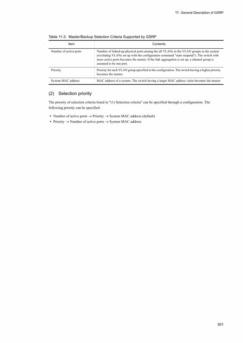
11. General Description of GSRP
Table 11-3: Master/Backup Selection Criteria Supported by GSRP
(2) Selection priority
The priority of selection criteria listed in "(1) Selection criteria" can be specified through a configuration. The following priority can be specified:
• Number of active ports → Priority → System MAC address (default)• Priority → Number of active ports → System MAC address
Item Contents
Number of active ports Number of linked-up physical ports among the all VLANs in the VLAN groups in the system (excluding VLANs set up with the configuration command "state suspend"). The switch with more active ports becomes the master. If the link aggregation is set up, a channel group is assumed to be one port.
Priority Priority for each VLAN group specified in the configuration. The switch having a higher priority becomes the master.
System MAC address MAC address of a system. The switch having a larger MAC address value becomes the master.
301

11. General Description of GSRP
11.3 GSRP Operation Overview
11.3.1 Status of GSRPGSRP operates on five states. The following table lists the states:
Table 11-4: GSRP Status List
11.3.2 Operation for System FailureThis following figure shows the operation on the system failure:
Status Contents
Backup The GSRP switch is in the backup state. When in the backup state, the GSRP switch blocks frames for each port on a VLAN in the VLAN group. The switch does not relay frames other than the GSRP control frame, and thus MAC address learning is not carried out. The switch always starts up in the backup state.
Backup(standby for master)
In this transient state, the switch confirms that the other GSRP switch is in the backup state or the backup (fixed) state before shifting from the backup state to the master state. In the backup (standby for master) state, the switch does not relay frames other than the GSRP control frame as in the backup state.
Backup(neighbor unknown)
The switch shifts to this state once it detects a timeout for receiving the GSRP Advertise frame from the other GSRP switch while in the backup state or in the backup (standby for master). Since the other-end GSRP switch is likely operating in the master, the switch stays in the backup until it receives the GSRP Advertise frame again or is shifted to the master by "set gsrp master". When in the backup (neighbor unknown) state, the switch does not relay frames other than the GSRP control frame as in the backup state.
Backup(fixed)
The state forcibly fixed to the backup. This state continues until the configuration is deleted. In the backup (fixed), the GSRP switch does not relay frames other than the GSRP control frame as in the normal backup.
Master The switch is in the master state. When in the master state, the GSRP switch forwards frames to each port on a VLAN in the VLAN group. All frames, including the GSRP control frame, are relayed and MAC address learning is performed.
302

11. General Description of GSRP
Figure 11-5: Operation for System Failure
If the LANSW module A, in the master state, is unable to send the GSRP Advertise frame properly due to a failure in the system, the LANSW module B detects a timeout for reception of the GSRP Advertise signal from the LANSW module A. The LANSW module B shifts to the backup (neighbor unknown) state. In the backup (neighbor unknown) state, as in the backup state, no frames are relayed. When the system enters the backup (neighbor unknown) state, it issues a message prompting the operator to check the states of the systems.
To shift the LANSW module B from the backup (neighbor unknown) to the master, GSRP provides two ways; the manual and automatic switchover.
• Manual switchoverGSRP supports "set gsrp master" command to manually shift a system to the master. The operator can use this command to shift the LANSW module B to the master state after confirming that the port on the LANSW module A is blocked and that the LANSW module A is not activated. The figure below shows operations after the "set gsrp master" command is executed.
303

11. General Description of GSRP
Figure 11-6: Operation after Execution of set gsrp master Command
• Automatic switchover (detecting a direct link failure)To enable the system to automatically shift to the master, execute configuration command "no-neighbor-to-master" with "direct-down". When the current system shifts to the backup (neighbor unknown) and it is found that the direct link port is shut down, it assumes the other-end system is faulty and shifts to the master automatically.
11.3.3 Operation for Link Failure
(1) Example of link failure operation
This following figure shows the operation on the link failure:
304

11. General Description of GSRP
Figure 11-7: Example of Link Failure Operation
This figure shows that the links between the LANSW module A and System C, the LANSW module A and System D, and the LANSW module B and System E failed while the LANSW module A and B operating in the master and backup respectively. If the number of active ports is set as the top priority for selection of the master/backup state, the LANSW module B chooses to be the master because it has more active ports than the LANSW module A. The LANSW module B temporarily shifts to the backup (standby for master) before entering the master. The LANSW module B then waits for the GSRP advertise frame from the LANSW module A. On receiving the frame, the LANSW module B confirms that the LANSW module A is in the backup state and then shifts to the master state. In this example, System E becomes unable to communicate with the LANSW module B, the master, because of the failure on the link between them.
305

11. General Description of GSRP
(2) Function to prevent successive switchover on an unstable link
GSRP uses the number of active ports as the selection criterion to determine the master and backup. If the link becomes unstable (being up or down frequently), the number of active ports increases, causing successive switchover between the master and backup.
To address this problem, GSRP provides a time delay, which can be set up using configuration command "port-up-delay". During this delay the up-link ports are excluded from the number of active ports until the operator confirms that the link restores stability. This prevents unintended switchover on an unstable link.
"port-up-delay" allows to specify the time delay in 1 second steps within 1 to 43200 seconds (12 hours). It is also possible to make the delay time infinite by specifying "infinity". Operation command "clear gsrp port-up-delay" is also available to immediately include the ports on the links that are stable into the active-port count, without waiting for the time delay specified using "port-up-delay".
11.3.4 Backup Stabilization FunctionThis fixes the GSRP switch to the backup forcibly. Configuration command "backup-lock" fixes the switch to backup (fixed) and keeps the state until the configuration is deleted. In the backup (fixed), the GSRP switch does not relay frames other than the GSRP control frame as in the normal backup.
11.3.5 GSRP VLAN group-only Control FunctionConfiguration command "gsrp limit-control" can limit the VLANs under GSRP control only to those that belong to VLAN groups. Because these VLANs are not under GSRP control you can always use them for communication.
11.3.6 GSRP Exception PortConfiguration command "gsrp exception-port" allows to operate the specified port as GSRP exception port. Freeing ports from the GSRP control makes them always available for communications independently of the master or backup.
306

11. General Description of GSRP
11.4 Layer 3 Redundancy Switchover Function
11.4.1 Outline of Layer 3 Redundancy Switchover FunctionThe layer 3 redundancy switchover enables to continue the existing communication in the event of a failure through the default gateway from the PC, by inheriting and switching over the same IP and MAC addresses between two switches.
The following figure outlines the GSRP layer 3 redundancy switchover function: In the following description, the network connecting PCs is called a downstream network and the destination IP network is called an upstream network. The GSRP master/backup switchover is reflected to the downstream network.
Figure 11-8: Outline of GSRP Layer 3 Redundancy Switchover Function
(1) Default gateway IP address
The same IP address and the same VLAN must be set to two GSRP switches to make the default gateways in redundant configuration with GSRP. The GSRP switch in the master state will have VLAN up and perform IP forwarding as the default gateway. The GSRP switch in the backup state will have VLAN down and will not perform IP relaying.
307
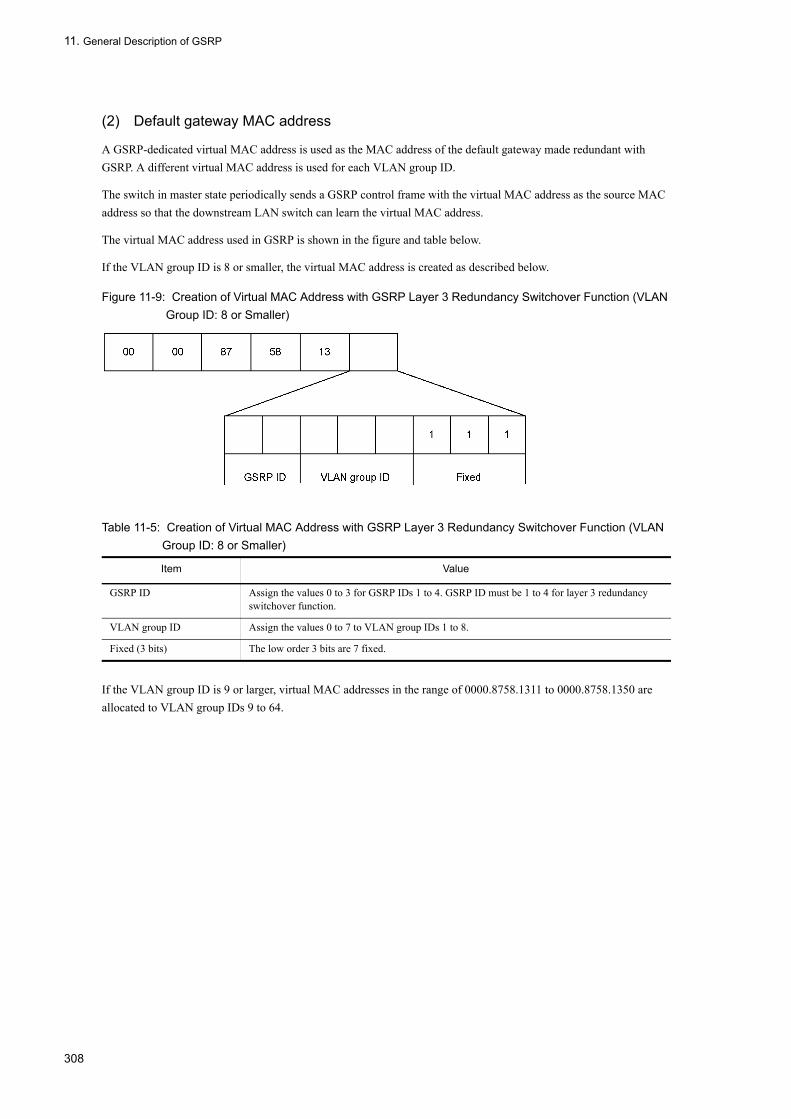
11. General Description of GSRP
(2) Default gateway MAC address
A GSRP-dedicated virtual MAC address is used as the MAC address of the default gateway made redundant with GSRP. A different virtual MAC address is used for each VLAN group ID.
The switch in master state periodically sends a GSRP control frame with the virtual MAC address as the source MAC address so that the downstream LAN switch can learn the virtual MAC address.
The virtual MAC address used in GSRP is shown in the figure and table below.
If the VLAN group ID is 8 or smaller, the virtual MAC address is created as described below.
Figure 11-9: Creation of Virtual MAC Address with GSRP Layer 3 Redundancy Switchover Function (VLAN Group ID: 8 or Smaller)
Table 11-5: Creation of Virtual MAC Address with GSRP Layer 3 Redundancy Switchover Function (VLAN Group ID: 8 or Smaller)
If the VLAN group ID is 9 or larger, virtual MAC addresses in the range of 0000.8758.1311 to 0000.8758.1350 are allocated to VLAN group IDs 9 to 64.
Item Value
GSRP ID Assign the values 0 to 3 for GSRP IDs 1 to 4. GSRP ID must be 1 to 4 for layer 3 redundancy switchover function.
VLAN group ID Assign the values 0 to 7 to VLAN group IDs 1 to 8.
Fixed (3 bits) The low order 3 bits are 7 fixed.
308

11. General Description of GSRP
11.5 GSRP Network Configuration
11.5.1 Load Balancing Configuration by VLAN GroupIn GSRP, the master/backup states are controlled for each VLAN group. Up to 64 VLAN groups can be set up on each GSRP switch. By combining more than one VLAN group, the load can be balanced among the VLAN groups to distribute traffics. The figure below outlines a load-balancing configuration.
In this figure, the LANSW module A functions in the master state for VLAN group 1 and in the backup state for VLAN group 2, while the LANSW module B works in the backup state for VLAN group 1 and in the master state for VLAN group 2.
Figure 11-10: Load Balancing Configuration
309

11. General Description of GSRP
When configuring load balancing by layer 3 redundancy switchover function, a communication path must be obtained between the GSRP switches in order for different systems to communicate between master state VLANs. This communication is performed through VLAN over direct link described in "11.5.3 Switchover Using Layer 3 Redundancy Switchover Due to Upstream Network Failure". The following figure outlines the load balancing configuration using the layer 3 redundancy switchover function:
In this figure, the LANSW module A and B are the masters for VLAN 10 and VLAN 20 respectively. The all communications to the upstream IP network go through the respective master system. The communications between VLAN10 and VLAN20 go through the VLAN over the direct link.
Figure 11-11: Load Balancing Configuration Using Layer 3 Redundancy Switchover
11.5.2 Multi-stage Configuration of GSRP GroupGSRP allows to configure more than one GSRP group in several stacks within the same layer 2 network. This ensures redundancy in large-scale networks. In a multilayered configuration of GSRP groups, a GSRP management VLAN is set for each GSRP group to limit destinations of the GSRP control frame. The following figure outlines a multilayered configuration of GSRP groups.
310

11. General Description of GSRP
Figure 11-12: Multi-stage Configuration of GSRP Group
In this figure, the LANSW module A and B constitute GSRP group 1, and Systems C and D constitute GSRP group 2. Each group functions independently. Therefore, even if the master/backup states are switched over in one group, the switchover does not affect the other group. The GSRP management VLAN is composed of the GSRP switch and other surrounding switches.
11.5.3 Switchover Using Layer 3 Redundancy Switchover Due to Upstream Network Failure
Suppose the upstream network side is released from the GSRP control and the IP routing is set up. When using the layer 3 redundancy switchover function, the upstream network side failure is detected by the IP routing function and the route is switched over.
When both GSRP switches are connected to the upstream network and one of the ports fails, the upstream network side also secures the communication path between GSRP switches in order to continue communication through the other GSRP switch.
The following figure provides an outline of configuration corresponding to upstream network failure and an example of communication path during failure.
311

11. General Description of GSRP
Figure 11-13: Configuration Corresponding to Failure in Upstream Network
312

11. General Description of GSRP
Figure 11-14: Communication Path for Upstream Network Failure
(1) Upstream network port configuration
The upstream network ports are configured as GSRP exception port (using the configuration command "gsrp-exception-port") to make it available for communications in both the master and backup. Then IP address and IP routing are set to connect to the upstream network.
The IP routing is set up to enable the two GSRP switches to communicate with the upstream network. The dynamic monitoring function over the dynamic or static routing is set up so that the failures in the upstream network can be detected.
Normally each GSRP switch is set up so that it can directly communicate with the upstream network. It is also set up so that it can continue communications with the upstream network through the neighboring GSRP switch if a failure occurs on the upstream network. Thus, the IP routing must be set up so that the route going through the adjacent GSRP switch to the upstream network has lower priority. For the static routing, the dynamic monitoring function is set up to detect failures and to periodically confirm the reachability.
(2) Setting between GSRP switches
Packets from the upstream network may arrive at the backup side GSRP switch because the communication is enabled
313

11. General Description of GSRP
from the upstream network to the two GSRP switches. In order to relay such packets to the master side GSRP switch, a layer 3 communication route is set between the GSRP switches.
The two GSRP switches are connected by a direct link to exchange GSRP Advertise frames over the GSRP management VLAN. Relaying between the GSRP switches is possible by configuring a VLAN other than GSRP management VLAN and IP routing on the direct link. However, the IP routing must be configured so that the route between the GSRP switches has a lower priority in order to directly relay downstream traffic to the upstream network.
314

11. General Description of GSRP
11.6 Notes on Using GSRP
(1) Using with other redundancy protocol
The following protocols cannot be used together.
• Spanning tree• Ring Protocol• VRRP• Uplink-failover
(2) Use of the port reset function
If a transmission device is installed between a physical port with the port reset function and the other-end switch, the latter can fail to properly detect a link-down of the port.
When using the port reset function, the network must be designed to have the other-end switch directly detect a port link-down.
(3) When using the port reset function in a load balancing configuration
Suppose multiple VLAN groups share a physical port of a switch with the port reset function setting. In this case if the switch switches over from master to backup in a VLAN group, the port is disconnected. This is because a link down occurs on the port despite the switch is still running as the master for other VLAN groups. In order to prevent temporary communication interruption due to this failure, design the network so that the same physical port is not shared by multiple VLAN groups.
The port that is temporarily brought down with the port reset function is treated as an active port during master/backup selection. It does not affect the master/backup selection of VLAN group running in the master state.
(4) VLAN configuration using GSRP
When using GSRP, all the VLANs are subject to the GSRP control. Thus, a VLAN port not the member of a VLAN group is blocked.
(5) Direct link failure detection
In the event of a failure in the transmission device installed on a direct link between systems, the system in the backup state may recognize that the failure has occurred in the other-end system, even though the latter system is operating properly in the master state, and therefore shift to the master state. As a result, the two systems may take on the master state simultaneously. The same situation can occur if there is a failure in one-way link of a direct link. Before using configuration command "no-neighbor-to-master" with "direct-down" set, set up the direct link in redundant configuration and design the network so that more than one route is available for exchanging GSRP advertise frames. The redundant configuration of the direct link can be achieved by using the link aggregation or using more than one ports. Either way provide the same result.
When the operation mode to change the system state from backup (neighbor unknown) to master is set to "direct-down", the system starts operating as the master if all ports specified for the direct link have failure. However, the system remains in backup state (neighbor unknown) if it does not receive any GSRP Advertise frame on the port specified for the direct link after the operations listed below. Enter the master transition command ("set gsrp master" operation command) to operate the system as the master.
• System start• Specify the operation command "restart vlan".• Specify the operation command "restart gsrp".
315

11. General Description of GSRP
• Specify "direct-down" in the configuration command "no-neighbor-to-master".• Set the direct link port using the configuration command "gsrp direct-link".• Applying the change to the running confirmation with the operation command "copy"
(6) Network construction using GSRP
A network using GSRP is basically a loop configuration. In configuring a GSRP-based network, the designer is required to take note of the following to prevent loop in the network.
• Before setting a GSRP configuration, disable the ports on the LANSW module by shutting down. Complete the configuration and ensure that the GSRP stable, and then start the operation.
• Start up one of the two systems constituting a GSRP group, set a configuration and, after ensuring that the system has shifted to the backup state, start up the other GSRP switch and set a configuration.
(7) Changing VLAN configuration with GSRP operated
GSRP uses the number of active ports as the selection criterion to determine the master and backup. The number of active ports represents the number of the VLANs belonging to VLAN groups. If ports are added to a VLAN or the network configuration is modified, the number of active ports increases or decreases. Normally the master and backup systems are updated with the same change, however, if the number of active ports on the backup system temporarily exceeds that of the master system, a switchover between the master and backup occurs.
To prevent this switchover, keep the following in mind when changing the VLAN configuration:
• Set "priority", as the master/backup selection criteria (specified using configuration command "selection-pattern") and perform the configuration with the master fixed by the priority.
• Before initiating a large-scale configuration change accompanied by the cabling change or rebooting the LANSW module, use this function to make one GSRP switch the backup and the other GSRP switch the master for all the VLAN groups, as required.
(8) Relaying the GSRP control frame with GSRP unaware
If the switches surrounding the GSRP switch are GSRP unaware, the GSRP control frame is flooded. As a result, the frame may be relayed beyond the relevant range because of the topology. To prevent unwanted control frame relay, set up a GSRP management VLAN on these GSRP unaware.
(9) Relaying of the GSRP Flush request frame
GSRP aware floods GSRP Flush request frames. In the network configuration in which GSRP aware relays GSRP Flush request frames, the GSRP aware software version Ver.10.4 or later is required. Because the GSRP switch does not flood GSRP Flush request frames, the configuration such as GSRP group multilayered configuration using the GSRP switch to relay GSRP Flush request frames is not supported.
(10) Remote management of the LANSW module under GSRP
When using GSRP, use a GSRP exception port (set up using "gsrp exception-port") for remote management of the LANSW modules.
(11) Interoperation
GSRP is a function based on specifications unique to the LANSW module. GSRP does not interoperate with ESRP (Extreme Standby Router Protocol) mounted on Extreme Networks' LAN switches and VSRP (Virtual Switch Redundant Protocol) incorporated in Foundry Networks' LAN switches.
316

11. General Description of GSRP
(12) CPU overload
If the CPU suffers from overloading, discarding or delayed processing of the GSRP advertise frames may arise, causing timeout message output or switchover. If the LANSW module frequently overloaded, increase the transmission interval and retention period of a GSRP advertise frame.
(13) Notes on setting of VLAN groups
If the software version of the remote system and GSRP aware is earlier than Ver.10.1, a VLAN group number which is 9 or larger cannot be used. If a VLAN group number which is 9 or larger is set when the layer 3 redundancy switchover function is being used, the same MAC address is set even for different GSRP groups in multiple GSRP configuration.
317

11. General Description of GSRP
318

12Configuration and Operation of GSRPThis chapter provides configuration examples for the GSRP functions.
12.1 Configuration
12.2 Operation
319
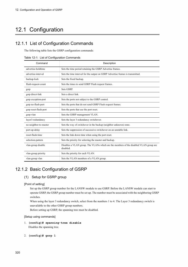
12. Configuration and Operation of GSRP
12.1 Configuration
12.1.1 List of Configuration CommandsThe following table lists the GSRP configuration commands:
Table 12-1: List of Configuration Commands
12.1.2 Basic Configuration of GSRP
(1) Setup for GSRP group
[Point of setting]Set up the GSRP group number for the LANSW module to use GSRP. Before the LANSW module can start to operate GSRP, the GSRP group number must be set up. The number must be associated with the neighboring GSRP switches.When using the layer 3 redundancy switch, select from the numbers 1 to 4. The Layer 3 redundancy switch is unavailable to the other GSRP group numbers.Before setting up GSRP, the spanning tree must be disabled.
[Setup using commands]
1. (config)# spanning-tree disable
Disables the spanning tree.
2. (config)# gsrp 1
Command Description
advertise-holdtime Sets the time period retaining the GSRP Advertise frames.
advertise-interval Sets the time interval for the output on GSRP Advertise frames is transmitted.
backup-lock Sets the fixed backup.
flush-request-count Sets the times to send GSRP Flush request frames.
gsrp Sets GSRP.
gsrp direct-link Sets a direct link.
gsrp exception-port Sets the ports not subject to the GSRP control.
gsrp no-flush-port Sets the ports that do not send GSRP Flush request frames.
gsrp reset-flush-port Sets the ports that use the port reset.
gsrp-vlan Sets the GSRP management VLAN.
layer3-redundancy Sets the layer 3 redundancy switchover.
no-neighbor-to-master Sets the way of switchover in the backup (neighbor unknown) state.
port-up-delay Sets the suppression of successive switchover on an unstable link.
reset-flush-time Sets the link down time when using the port reset.
selection-pattern Sets the priority for selecting the master and backup.
vlan-group disable Disables a VLAN group. The VLANs which are the members of the disabled VLAN group are disabled.
vlan-group priority Sets the priority for each VLAN.
vlan-group vlan Sets the VLAN members of a VLAN group.
320

12. Configuration and Operation of GSRP
Sets the GSRP group number to 1. This command starts the GSRP operation.
[Note]All VLANs become subject to GSRP, after setting up the GSRP group number. Every VLAN port is blocked when no VLAN group is set up.
(2) Setup for GSRP management VLAN
[Point of setting]Specify the VLAN to be used as a GSRP management VLAN. Omitting this setup, the GSRP management VLAN is set to 1.The GSRP management VLAN is used to exchange GSRP control frames. For this VLAN, set up a direct link with the GSRP switch. If GSRP aware is to be used, set up a connecting port with the port. For GSRP aware, also set up the same VLAN on the port connected with the GSRP switch.
[Setup using commands]
1. (config)# gsrp 1
Moves to the GSRP configuration mode.
2. (config-gsrp)# gsrp-vlan 5
Uses VLAN 5 as the GSRP management VLAN.
(3) Setup for direct link
[Point of setting]Set up the port used for the GSRP direct link. The direct link must be set up for the Ethernet or port-channel interface.Before using the direct link failure detection, it is recommended to set up the direct link redundantly. This reduces the risk of direct link failures that may be caused by any reason other than the other-end system failure. The direct link can be made redundant by using the link aggregation or using more than one line. Either of them is similarly effective.
[Setup using commands]
1. (config)# interface range gigabitethernet 0/1-2
Moves to the Ethernet interface configuration mode with ports 0/1 and 0/2. Specifies more than one port to make the direct link redundant.
2. (config-if-range)# gsrp 1 direct-link
Specifies ports 1/0 and 1/2 for direct links with GSRP group number 0.
(4) Setting VLAN group
[Point of setting]Set the VLAN group and its VLAN members operated under GSRP. Communications are only available to the VLANs, the members of the VLAN group set as the master. More than one VLAN group may be set up. Each VLAN group controls the master and backup. For the VLAN group and its member VLANs, set up the same as the neighboring GSRP switches.Use "vlan-group vlan add" and "vlan-group vlan remove" to add and delete a VLAN from a VLAN group, respectively. Issuing "vlan-group vlan" again with the "vlan-group vlan" has been set up the specified VLAN ID
321

12. Configuration and Operation of GSRP
list replaces the existing one.To disable a VLAN group communication, use "vlan-group disable" to disable the VLAN group.
[Setup using commands]
1. (config)# gsrp 1
Moves to the GSRP configuration mode.
2. (config-gsrp)# vlan-group 1 vlan 10,20
Creates VLAN group 1, and make VLANs 10 and 20 its members.
3. (config-gsrp)# vlan-group 1 vlan add 30
Adds VLAN 30 to VLAN group 1.
4. (config-gsrp)# vlan-group 1 vlan remove 20
Deletes VLAN 20 from VLAN group 1.
5. (config-gsrp)# vlan-group 1 vlan 100,200
Sets VLANs 100 and 200 as the members of VLAN group 1. The existing settings are overwritten and VLANs 100 and 200 become the member VLANs.
[Note]When using GSRP, all the VLANs are subject to the GSRP control. Thus, a VLAN port not the member of a VLAN group is blocked.
12.1.3 Setting Selection of Master or Backup
(1) Setup for selecting master and backup
[Point of setting]Set up the priority of applying the criteria (i.e., number of active ports, priority, system MAC address) that controls switchover between the GSRP master and backup. For the applicable criteria priority, select either order: "Number of active ports → Priority → System MAC address" or "Priority → Number of active ports → System MAC address".It is recommended to provide "Number of active ports" with the top priority. This is because, when performing any work accompanied by increasing/decreasing the number of VLAN ports or link down, the master and backup states can be stable on the way of completing the work.
[Setup using commands]
1. (config)# gsrp 1
Moves to the GSRP configuration mode.
2. (config-gsrp)# selection-pattern priority-ports-mac
Selects "Priority → Number of active ports → System MAC address" in order.
(2) Setup for VLAN group priority
[Point of setting]Set up the priority for each VLAN group. The larger the value, the higher the priority. Setting up the priority determines the LANSW module having precedence over the other with the same number of active ports.
322

12. Configuration and Operation of GSRP
This allows to establish load balancing with VLAN groups by setting up more than one VLAN group and differentiating the priorities among them.
[Setup using commands]
1. (config)# gsrp 1
Moves to the GSRP configuration mode.
2. (config-gsrp)# vlan-group 1 priority 80
Sets the priority of VLAN group 1 to 80.
(3) Setup for fixed backup
[Point of setting]The fixed backup forcibly moves all the VLAN groups on one GSRP switch to the backup. Before initiating a large-scale configuration change accompanied by the change of cabling or rebooting the LANSW module, use this function to fix the other-end GSRP switch to the master of all the VLAN groups, as required.
[Setup using commands]
1. (config)# gsrp 1
Moves to the GSRP configuration mode.
2. (config-gsrp)# backup-lock
Sets the fixed backup. This sets up all the VLAN groups as the backup, and the other-end GSRP the master.
12.1.4 Setting Layer 3 Redundancy Switchover[Point of setting]
Set up the layer 3 redundancy switchover for GSRP. The layer 3 redundancy switchover is only available to GSRP group numbers 1 to 4.When using the layer 3 redundancy switchover, set up the current VLAN IP address the same as the other-end GSRP switch. For setting up the IP address, see "Configuration Settings, Vol. 1, 17.9 VLAN Interface". Using the layer 3 redundancy switchover, the setup for switching over the upstream network is required. For details, see "11.5.3 Switchover Using Layer 3 Redundancy Switchover Due to Upstream Network Failure".
[Setup using commands]
1. (config)# gsrp 1
Moves to the GSRP configuration mode.
2. (config-gsrp)# layer3-redundancy
Sets up the layer 3 redundancy switchover.
12.1.5 Setting GSRP VLAN group-only control[Point of setting]
Enables the GSRP VLAN group-only control function. When this function is enabled, GSRP controls only the VLANs that belong to VLAN groups. The VLAN ports that do not belong to any VLAN group are always able to forward frames.
323

12. Configuration and Operation of GSRP
You can use the GSRP VLAN group-only control function for the following purposes:•To make it easier for Layer 3 redundancy switching to provide a connection to the upstream network•To use VLANs that do not belong to any GSRP VLAN group as VLANs that are not under GSRP control
•To remotely manage the Switches
[Setup using commands]
1. config)# gsrp limit-control
Enables the GSRP VLAN group-only control function.
12.1.6 Setting GSRP Exception Port[Point of setting]
Set up the ports to be excluded from GSRP control for port or link aggregations. This setup is applied to the Ethernet or port-channel interface. Once it is set up, the interface is fixed to forwarding independent of the GSRP state.The GSRP exception ports are useful when remotely managing the LANSW module with GSRP enabled or for the connecting port to the upstream of the layer 3 redundancy switchover.
[Setup using commands]
1. (config)# interface gigabitethernet 0/1
Changes to port 0/1 Ethernet interface configuration mode.
2. (config-if)# gsrp exception-port
Sets port 0/1 as a GSRP exception port.
12.1.7 Setting GSRP Parameters
(1) Setup for preventing successive switchover on unstable link
GSRP refers to the number of active ports when selecting switches for the master or backup. If the port becomes unstable (enabled or disabled frequently), the number of active ports increases and switchover between the master and backup occur successively. If the port is unstable, such unwanted switchover can be suppressed by specifying the delay time using this command.
[Point of setting]Set up the time delay until a port becomes eligible to operate as the active port.If "infinity" is specified for the parameter, the delay time assumed to be infinite, and the result is not automatically reflected in the active-port count. Without this setting, the time delay after the port enabled is immediately (without delay) reflected in the active-port count.
[Setup using commands]
1. (config)# gsrp 1
Moves to the GSRP configuration mode.
2. (config-gsrp)# port-up-delay 10
Sets the time delay of reflection in the active-port count to 10 seconds.
3. (config-gsrp)# port-up-delay infinity
Sets the time delay of reflection in the active-port count to infinite. If you want to make a port eligible as an active
324

12. Configuration and Operation of GSRP
port after enabling it, use "clear gsrp port-up-delay".
(2) Setup for transmitting intervals and retaining period of GSRP Advertise frames
[Point of setting]Set up the transmitting intervals and the retaining period of GSRP Advertise frames. Specify the value of "advertise-holdtime" greater than that of "advertise-interval". When setting a value less than "advertise-interval", reception timeout of a GSRP Advertise frame will be detected.
[Setup using commands]
1. (config)# gsrp 1
Moves to the GSRP configuration mode.
2. (config-gsrp)# advertise-interval 5
Sets the transmission intervals for GSRP Advertise frame to 5 seconds.
3. (config-gsrp)# advertise-holdtime 20
Sets the time period to retain a GSRP Advertise frame to 20 seconds. This allows failure in receiving a GSRP Advertise frame up to three times.
[Note]If the CPU suffers from overloading, the GSRP "advertise" frames the LANSW module exchanges may be discarded or delayed for processing and timeout message may be poured out or state transitions may arise. If the LANSW module frequently overloaded, increase the transmission interval and retention period of a GSRP advertise frame.
(3) Setup for port not sending GSRP Flush request frames
[Point of setting]Set up ports that do not send GSRP Flush request frames. This setup is applied to Ethernet or port-channel interface.GSRP Flush requests are sent to the all ports subject to the GSRP management VLAN except for those that are set up as the direct link and port reset. This function is convenient when the port reset is undesired for connecting to GSRP unaware. Note, however, in such a configuration the communication is not restored until the GSRP unaware MAC address table is cleared by aging after switchover between the master and backup. It is generally recommended to use the port reset function for connecting to GSRP unaware.
[Setup using commands]
1. (config)# interface gigabitethernet 0/1
Changes to port 0/1 Ethernet interface configuration mode.
2. (config-if)# gsrp 1 no-flush-port
Sets to prevent the port 0/1 from sending GSRP Flush request frames.
(4) Set up the number of times for sending GSRP Flush request frames
[Point of setting]Set up the number of times to send GSRP Flush request frames to clear the MAC address tables for the neighboring switches.It is set to three times of sending GSRP flush request frames by default. The larger the number, the more robust the
325
12. Configuration and Operation of GSRP
LANSW module becomes against frame losses.
[Setup using commands]
1. (config)# gsrp 1
Moves to the GSRP configuration mode.
2. (config-gsrp)# flush-request-count 5
Sets the number of times to send GSRP Flush request frame to 5.
12.1.8 Setting Port ResetThis function is used when connecting to GSRP unaware. The switch turned to the backup after the master/backup switchover disconnects the ports with the port reset enabled from the link temporarily.
(1) Setup for applied ports
[Point of setting]Set up the port reset function. This setup is applied to Ethernet or port-channel interface.
[Setup using commands]
1. (config)# interface gigabitethernet 0/1
Changes to port 0/1 Ethernet interface configuration mode.
2. (config-if)# gsrp 1 reset-flush-port
Sets the port reset for port 0/1.
(2) Setting the time period for shutting down the port
[Point of setting]Set up the time period over which the port is shut down when using the port reset. The default is 3 seconds. The setup is convenient when using the port reset and the other-end switch is accompanied by a longer link down time. When connecting to a system for which the link down detecting time can be set up (using configuration command "link debounce"), make sure to set the port down time longer than it.
[Setup using commands]
1. (config)# gsrp 1
Moves to the GSRP configuration mode.
2. (config-gsrp)# reset-flush-time 5
Sets the port down time to 5 seconds.
12.1.9 Setting Direct Link Failure Detection[Point of setting]
When switching over from the backup (neighbor unknown) to master due to a direct link failure, this setup allows to select the way of switchover between the manual (the master transition command) or automatic (the Direct Link failure detection).When using the direct link failure detection to automatically switch the state, it is recommended to set up the direct
326

12. Configuration and Operation of GSRP
link redundantly to reduce the risk of direct link failures caused by any reason other than the the other-end system failure. The direct link can be made redundant by using the link aggregation or using more than one line. Either of them is similarly effective.
[Setup using commands]
1. (config)# gsrp 1
Moves to the GSRP configuration mode.
2. (config-gsrp)# no-neighbor-to-master direct-down
Sets the direct link failure detection as to move to the master automatically if the direct link fails.
327

12. Configuration and Operation of GSRP
12.2 Operation
12.2.1 List of Operation CommandsThe following table lists the GSRP operation commands:
Table 12-2: List of Operation Commands
12.2.2 Checking GSRP StateThe information that can be checked using GSRP functions on the LANSW module are as follows:
(1) Checking after configuration
Use "show gsrp" to check for the GSRP configuration. Use "show access-filter" to make sure that the LANSW module is updated with GSRP set up in the configuration. Make sure that, between the LANSW module and the other-end system constituting one GSRP group, the master/backup selection pattern, layer 3 redundancy switchover function setting, VLAN group numbers (VLAN Group IDs), and VLANs belonging to the VLAN group are the same. If the layer 3 redundancy switchover function is set up, make sure that IP address settings of VLANs belonging to the VLAN group are the same as the remote system. For details on checking for the IP address, see "Configuration Settings, Vol. 1, 17.11.2 Checking VLAN Status" and "Configuration Settings, Vol. 3, 2.2.2 Checking IPv4 Interface Up/Down Status", or "Configuration Settings, Vol. 3, 16.2.2 Checking IPv6 Interface Up/Down Status". Note that, for VLANs belonging to the backup VLAN group the interface is shut down.
The following images show the results of executing "show gsrp detail" and "show gsrp vlan-group:"
Command Description
show gsrp Displays the GSRP information.
show gsrp aware Displays the GSRP aware information.
clear gsrp Clears the GSRP statistics.
set gsrp master Moves from the backup (neighbor unknown) to master.
clear gsrp port-up-delay Immediately updates the member port of the VLAN defined in the VLAN group to active state without the time delay defined by configuration command "port-up-delay".
restart gsrp Restarts the GSRP program.
dump protocols gsrp Outputs the detailed event-trace information and the control-table information collected by the GSRP program into a file.
328

12. Configuration and Operation of GSRP
Figure 12-1: Execution Result of "show gsrp detail" Command
> show gsrp detailDate 2005/11/07 22:24:36 UTC GSRP ID: 1 Local MAC Address : 0012.e205.0000 Neighbor MAC Address : 0012.e205.0011 Total VLAN Group Counts : 2 GSRP VLAN ID : 105 Direct Port : 0/10-11 GSRP Exception Port : 0/1-5 No Neighbor To Master : manual Backup Lock : disable Port Up Delay : 0 Last Flush Receive Time : - Layer 3 Redundancy : On Local Neighbor Advertise Hold Time : 5 5 Advertise Hold Timer : 4 - Advertise Interval : 1 1 Selection Pattern : ports-priority-mac ports-priority-mac VLAN Group ID Local State Neighbor State 1 Backup Master 8 Master Backup>
Figure 12-2: Execution Result of "show gsrp vlan-group" Command
> show gsrp 1 vlan-group 1Date 2005/11/07 22:25:13 UTC GSRP ID: 1 Local MAC Address : 0012.e205.0000 Neighbor MAC Address : 0012.e205.0011 Total VLAN Group Counts : 1 Layer 3 Redundancy : On VLAN Group ID : 1 VLAN ID : 110,200-210 Member Port : 0/6-8 Last Transition : 2005/11/07 22:20:11 (Master to Backup) Transition by reason : Priority was lower than neighbor's Master to Backup Counts : 4 Backup to Master Counts : 4 Virtual MAC Address : 0000.8758.1307 Local Neighbor State : Backup Master Acknowledged State : Backup - Advertise Hold Timer : 3 - Priority : 100 101 Active Ports : 3 3 Up Ports : 3 ->
(2) Checking during operation
Make sure that in the LANSW module and in the partner system constituting the same GSRP group, the VLAN group state is set to the master for one of the systems and there is no more than one master residing within the same VLAN group. To check for the VLAN group state from the LANSW module, use "show gsrp".
329

12. Configuration and Operation of GSRP
Figure 12-3: Example of Executing "show gsrp" Command
> show gsrpDate 2005/11/07 22:28:38 UTC GSRP ID: 10 Local MAC Address : 0012.e205.0000 Neighbor MAC Address : 0012.e205.0011 Total VLAN Group Counts : 2 Layer 3 Redundancy : On VLAN Group ID Local State Neighbor State 1 Backup Master 8 Master Backup>
12.2.3 State Transition Using Command"set gsrp master" allows transition from the backup (neighbor unknown) to master.
This command is valid only for the backup (neighbor unknown). Execute this command only after confirming that the relevant VLAN group of the remote system is in the backup state.
Figure 12-4: Execution Result of "set gsrp master" Command
> set gsrp master 1 vlan-group 1Transit to Master. Are you sure? (y/n):y>
12.2.4 Immediately Activating Delayed PortsThe configuration command "clear gsrp port-up-delay" immediately counts the port subject to the successive switchover prevention (specified by configuration command "port-up-delay") as an active port without the predefined time delay.
Figure 12-5: Execution Result of "clear gsrp port-up-delay" Command
> clear gsrp port-up-delay port 0/1>
330
13VRRPVRRP (Virtual Router Redundancy Protocol) is a hot-standby function that is designed to provide terminals with alternative path through another router on the same Ethernet in the event of a router failure. This chapter describes the VRRP function.
13.1 VRRP Overview
13.2 Configuration
13.3 Operation
331
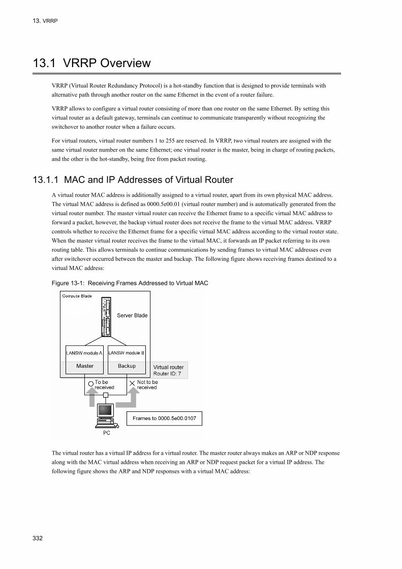
13. VRRP
13.1 VRRP Overview
VRRP (Virtual Router Redundancy Protocol) is a hot-standby function that is designed to provide terminals with alternative path through another router on the same Ethernet in the event of a router failure.
VRRP allows to configure a virtual router consisting of more than one router on the same Ethernet. By setting this virtual router as a default gateway, terminals can continue to communicate transparently without recognizing the switchover to another router when a failure occurs.
For virtual routers, virtual router numbers 1 to 255 are reserved. In VRRP, two virtual routers are assigned with the same virtual router number on the same Ethernet; one virtual router is the master, being in charge of routing packets, and the other is the hot-standby, being free from packet routing.
13.1.1 MAC and IP Addresses of Virtual RouterA virtual router MAC address is additionally assigned to a virtual router, apart from its own physical MAC address. The virtual MAC address is defined as 0000.5e00.01 (virtual router number) and is automatically generated from the virtual router number. The master virtual router can receive the Ethernet frame to a specific virtual MAC address to forward a packet, however, the backup virtual router does not receive the frame to the virtual MAC address. VRRP controls whether to receive the Ethernet frame for a specific virtual MAC address according to the virtual router state. When the master virtual router receives the frame to the virtual MAC, it forwards an IP packet referring to its own routing table. This allows terminals to continue communications by sending frames to virtual MAC addresses even after switchover occurred between the master and backup. The following figure shows receiving frames destined to a virtual MAC address:
Figure 13-1: Receiving Frames Addressed to Virtual MAC
The virtual router has a virtual IP address for a virtual router. The master router always makes an ARP or NDP response along with the MAC virtual address when receiving an ARP or NDP request packet for a virtual IP address. The following figure shows the ARP and NDP responses with a virtual MAC address:
332

13. VRRP
Figure 13-2: ARP and NDP Responses with Virtual MAC Address
To transfer frames, any hosts including a PC that uses a virtual router as the default router map virtual IP addresses to virtual MAC addresses within its ARP cache table. Since these hosts transfer frames to virtual MAC addresses whenever sending frames to virtual routers, they can continue communications even if a VRRP master to backup switchover occurs.
13.1.2 Failure Detection Mechanism for VRRPThe master virtual router periodically (at 1 second intervals by default) sends out a packet called ADVERTISEMENT for state check from the IP interface with virtual router set up. Upon receipt of the ADVERTISEMENT packet from the master router, the backup router confirms that the master router is free from failure. The following figure shows sending ADVERTISEMENT packets:
Figure 13-3: Sending ADVERTISEMENT Packets
The master virtual router cannot send ADVERTISEMENT packets if is encountered with any failure. The failure could be entire system shutdown, failures preventing the IP interface set up as a virtual router from sending packets or a cable
333

13. VRRP
disconnected.
The backup virtual router assumes the master virtual router to be faulty if no ADVERTISEMENT packet is received from the master router for a specific period of time, then becomes the master.
13.1.3 Selecting Master
(1) Priority
VRRP uses the priority to select a master virtual router from more than one virtual router. The priority can be set up for virtual routers. The numbers 1 to 255 are available for the priority; set to 100 by default. The higher the number, the higher the priority is. If the IP address of an interface and that of the virtual router is the same (IP address owner), the highest priority 255 is automatically set for the virtual router. The following figure shows the master router selecting scheme:
Figure 13-4: Selecting Master
In this figure, virtual router A with the top priority is the master. If virtual router A fails, virtual router B, the next-prioritized virtual router becomes the master.
To clearly differentiate the router to be the master from others, set up different priorities for the virtual routers with the same virtual router number on the same Ethernet. Do not set up more than one virtual router with the same priority or unexpected activities may arise since which one becomes the master is unknown.
(2) Automatic switch back and its suppression
In a VRRP configuration, a backup virtual router with the top priority automatically changes to the master if it finds a mater with a lower priority. Conversely, if the master virtual router finds a router with a higher priority, it automatically changes to the backup.
This automatic switch back can be inhibited through a setup. There are two ways to inhibit the switch back.
Suppression through PREEMPT modeTurn the PREEMPT mode off using configuration command "no vrrp preempt" if automatic switch back is undesirable. With PREEMPT mode off, the router does not become the master even if it finds a virtual router with a lower priority operating as the master.
Suppress using suppress timerTo delay the starting of the automatic switch back for a certain time period, use configuration command "vrrp preempt delay" to set up the suppress timer. The timer delays the start of the automatic switch back operation after it found the cause of the back operation. The actual switch back requires the set time plus several seconds to complete.
Neither of the above ways is effective to suppress the switch back if the target virtual router is the IP address owner with the priority of 255.
When the current backup virtual router finds that the current master virtual router is inoperative due to a failure and it
334

13. VRRP
has the top priority among the remaining virtual routers, it become the master even if the switch back is suppressed.
Manual switch backThe switch back on virtual routers can be activated using operation command "swap vrrp" even if the automatic switch back is suppressed.If this command is executed on a backup virtual router kept in backup state by the suppressing automatic switch back, when its priority is higher than the current master, the backup virtual router becomes the master.
13.1.4 Authenticating ADVERTISEMENT PacketsADVERTISEMENT packets use the multicast address (224.0.0.18 for IPv4 and ff02::12 for IPv6) under a link local scope. Owing to the fact that the virtual routers do not receive packets if the TTL or HopLimit in IP header is longer than 255, remote attacks over the routers can be avoided. The LANSW module supports authenticating the VRRP ADVERTISEMENT packets using text passwords. When a password not exceeding eight characters is set for a virtual router, an ADVERTISEMENT packet with a different password is discarded. The figure below shows the case where the password does not match.
Figure 13-5: Password Mismatch
As shown above, since the passwords of virtual router B differs from those of virtual routers A and C, virtual routers A and C discard the ADVERTISEMENT packets received from virtual router B. Virtual router C only receives and processes the ADVERTISEMENT packets from virtual router A. This prevents the operation of inappropriately installed virtual routers that can fail in ADVERTISEMENT packet authentication.
13.1.5 Accept ModeA virtual router other than the IP address owner does not respond to packets to the virtual IP address, even if it is the master. To bypass this and check for the network devices, "ping" is generally used.
The LANSW module supports the Accept mode. The Accept mode makes the master virtual router respond to packets to the virtual IP address. To monitor the virtual router state remotely, set up the Accept mode using configuration command "vrrp accept". This allows the master virtual router other than the IP address owner to receive ICMP echo request packets and return ICMP echo reply packets.
13.1.6 Tracking functionalityThe LANSW module supports tracking functionality in the format of failure monitoring interfaces and VRRP polling. The tracking functionality monitors failures on the network and dynamically changes the priorities assigned to virtual routers.
If a failure occurs on an interface on which a virtual router is configured, a backup router takes over as the master router. However, if a failure occurs on an interface on which no virtual router is configured, such as an IP interface, a port channel interface, or an Ethernet interface that is the destination of packet routing, no backup router takes over as
335

13. VRRP
the master even if communication is disabled.
As a unique additional functionality, the Switch provides functionality for monitoring the VLAN interfaces, port channel interfaces, and Ethernet interfaces on it and for lowering the priorities of virtual routers if the interfaces go down. This tracking functionality is called failure monitoring interfaces. Note that an IP address must be assigned to a VLAN interface if you want to monitor it for failures.
The failure monitoring interfaces cannot detect failures that occur beyond the routers because they can only monitor the failures that are manifested as interface-down failures. The Switch has another special functionality that can be used as tracking functionality. VRRP polling monitors the specified VLAN interfaces, checks the reachability of the specified destinations by pinging them, and lowers the priorities of virtual routers if no reply is returned. This tracking functionality is called VRRP polling.
You can use the failure monitoring interfaces to monitor the failures that occur between the Switch and neighboring devices. You can use VRRP polling to monitor the failures that occur between the Switch and devices located beyond the routers.
Two methods are provided for changing the priorities of virtual routers.
One method is priority switching. Priority switching allows you to change the priority of a virtual router to the value specified in the vrrp track priority configuration command when the tracking functionality detects a failure on it.
The other is priority decrement. Priority decrement subtracts the value specified in the vrrp track decrement configuration command for the failure monitoring interfaces from the priority value of a virtual router when the tracking functionality detects a failure.
For priority switching, you can specify one failure monitoring interface or one instance of VRRP polling. For priority decrement, you can specify multiple failure monitoring interfaces and multiple instances of VRRP polling.
When the priority of a virtual router becomes 0 as a result of executing tracking functionality, the IP interface on which the virtual router is configured goes down.
Table 13-1: Combination of Priority Control and Monitoring Methods
(1) Failure monitoring interface
The following figure schematically illustrates the failure monitoring interface for virtual routers:
Priority Control Method Capability of Detecting Interface Shutdown
VRRP Polling
Priority switchover method Only one setting allowed Only one setting allowed
Priority decrease method Multiple settings allowed Multiple settings allowed
336
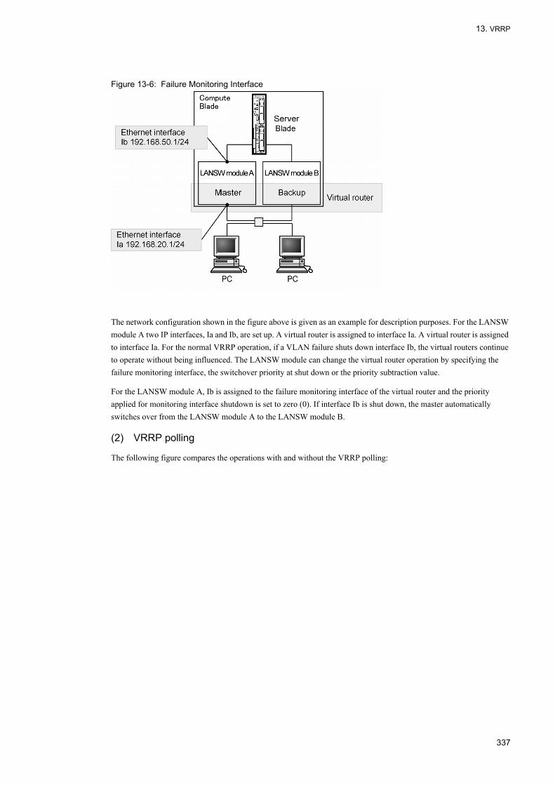
13. VRRP
Figure 13-6: Failure Monitoring Interface
The network configuration shown in the figure above is given as an example for description purposes. For the LANSW module A two IP interfaces, Ia and Ib, are set up. A virtual router is assigned to interface Ia. A virtual router is assigned to interface Ia. For the normal VRRP operation, if a VLAN failure shuts down interface Ib, the virtual routers continue to operate without being influenced. The LANSW module can change the virtual router operation by specifying the failure monitoring interface, the switchover priority at shut down or the priority subtraction value.
For the LANSW module A, Ib is assigned to the failure monitoring interface of the virtual router and the priority applied for monitoring interface shutdown is set to zero (0). If interface Ib is shut down, the master automatically switches over from the LANSW module A to the LANSW module B.
(2) VRRP polling
The following figure compares the operations with and without the VRRP polling:
337
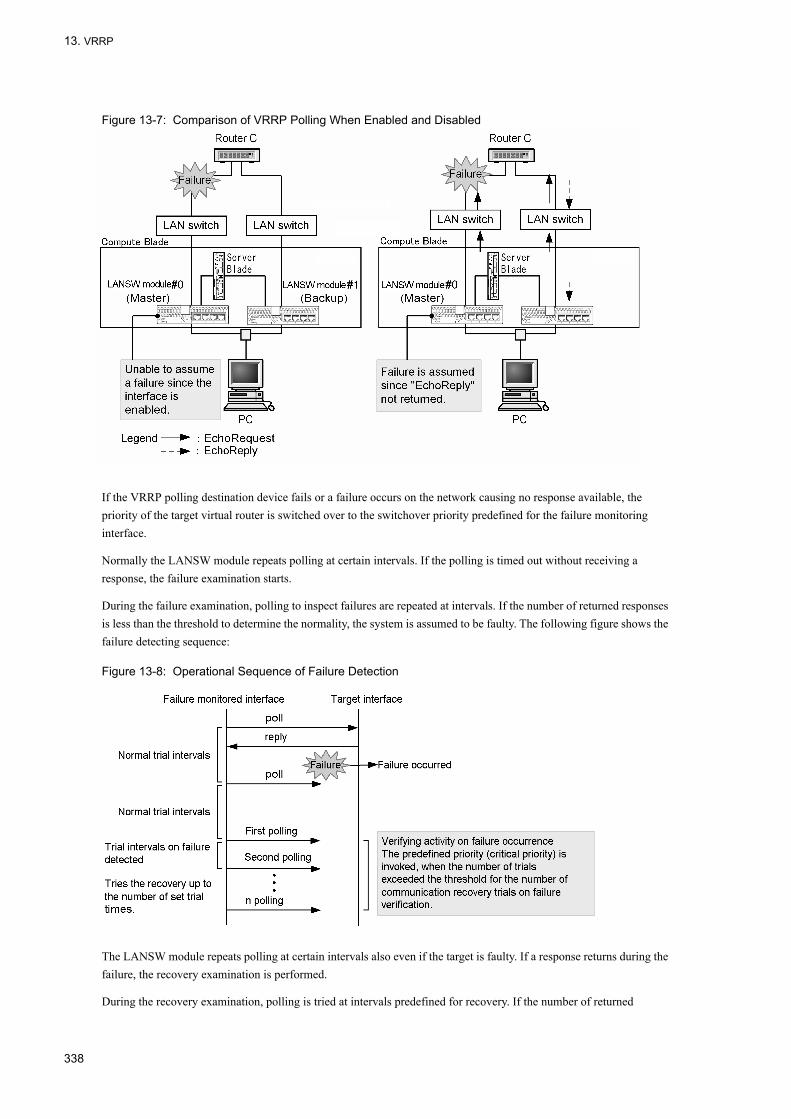
13. VRRP
Figure 13-7: Comparison of VRRP Polling When Enabled and Disabled
If the VRRP polling destination device fails or a failure occurs on the network causing no response available, the priority of the target virtual router is switched over to the switchover priority predefined for the failure monitoring interface.
Normally the LANSW module repeats polling at certain intervals. If the polling is timed out without receiving a response, the failure examination starts.
During the failure examination, polling to inspect failures are repeated at intervals. If the number of returned responses is less than the threshold to determine the normality, the system is assumed to be faulty. The following figure shows the failure detecting sequence:
Figure 13-8: Operational Sequence of Failure Detection
The LANSW module repeats polling at certain intervals also even if the target is faulty. If a response returns during the failure, the recovery examination is performed.
During the recovery examination, polling is tried at intervals predefined for recovery. If the number of returned
338

13. VRRP
responses exceeds the threshold to determine the normality during the recovery examination, the system is assumed to be restored and normal. The following figure shows the operation sequence for the failure recovery:
Figure 13-9: Operational Sequence of Failure Recovery
If an interface fails, the VRRP polling assumes it faulty and waits for the recovery of the interface. When the interface is restored, it resumes polling and starts the switch back if the recovery examination assumes normality.
The destination IP address of VRRP polling depends on each router's routing table if it exists in a network beyond the router. Therefore, as shown in "Figure 13-10: When Transmission/Reception Interfaces Do Not Match", the interface that receives the reply from VRRP polling may not be the same interface that transmits VRRP polling. In this case, the sending and receiving interfaces can be validated by specifying the reception interface check (using configuration command "track check-reply-interface"). The corresponding packet is discarded when the transmission interface does not match the reception interface. There is no guarantee when interfaces on a network not under the control of the local system do not match as shown in "Figure 13-11: Interface Mismatch on Network Not under by the Local System".
Figure 13-10: When Transmission/Reception Interfaces Do Not Match
339

13. VRRP
Figure 13-11: Interface Mismatch on Network Not under by the Local System
13.1.7 Supported VRRP specificationsThe Switch supports multiple VRRP specifications. Therefore, you can configure virtual routers as desired according to the specification used in an existing system. To select a VRRP specification for the virtual routers, specify a VRRP operation mode.
The following table describes the supported VRRP specifications and the commands for specifying the VRRP operation mode.
Table 13-2: VRRP specifications and the commands for specifying the VRRP operation mode
The format of an advertisement packet and the meaning of the fields differ according to the specification. If a switch that participates in a virtual router uses a different specification, the switch might regard an advertisement packet sent from another switch as an invalid packet and discard it. In this case, multiple switches might become the master router. To prevent this problem, configure the same VRRP operation mode on all the switches that participate in a virtual router.
(1) Overview of the default operation for IPv4 virtual routers
IPv4 virtual routers use VRRP packets of VRRP protocol version 2 (specified in RFC 3768) to send and receive advertisements. The IPv4 virtual routers can authenticate advertisement packets.
Determine the failure detection time based on the sending interval of advertisement packets configured for the Switch. The sending interval of advertisement packets is set in one-second units.
(2) Overview of the default operation for IPv6 virtual routers
IPv6 virtual routers use VRRP packets of VRRP protocol version 3 (specified in draft-ietf-vrrp-ipv6-spec-02) to send and receive advertisements. The IPv6 virtual routers can authenticate advertisement packets.
Determine the failure detection time based on the sending interval of advertisement packets configured for the Switch. The sending interval of advertisement packets is set in one-second units.
Standards Command for specifying the VRRP operation mode
IPv4 RFC 3768 The mode is set by IPv4 virtual routers by default.
IPv6 draft-ietf-vrrp-ipv6-spec-02 The mode is set by IPv6 virtual routers by default.
draft-ietf-vrrp-ipv6-spec-07 vrrp ietf-ipv6-spec-07-mode
340

13. VRRP
(3) Overview of the operation for IPv6 virtual routers in vrrp ietf-ipv6-spec-07-mode
Another VRRP operation mode supported by IPv6 virtual routers is vrrp-ietf-ipv6-spec-07-mode.
The IPv6 virtual routers in this mode use VRRP packets of VRRP protocol version 3 (specified in draft-ietf-vrrp-ipv6-spec-07) to send and receive advertisements.
Determine the failure detection time based on the sending interval of advertisement packets configured for the Switch. The sending interval of advertisement packets is set in one-second units.
In this mode, the IPv6 virtual routers cannot authenticate advertisement packets.
13.1.8 Notes on Using VRRP
(1) Mixed use of VRRP ,GSRP and Uplink-failover
VRRP, GSRP and Uplink-failover cannot be installed together within a system.
(2) Sending interval of advertisement packets
In the cases listed below, the VRRP advertisement packets to be sent and received by the Switch might be dropped or their processing might be delayed, resulting in state transitions. If state transitions occur frequently, specify a longer sending interval for the VRRP advertisement packets.
•When the CPU load on the Switch is excessive•When too many virtual routers are configured on the Switch•When network load is excessive
•When a virtual router consists of three or more Switches
(3) Monitoring multi-path route through VRRP polling
The VRRP polling function cannot monitor the multi-path route.
(4) Input of track Command
If the configuration is changed by entering two or more "track" commands consecutively, the virtual router in the backup state may change into the master state. To enter the "track" command consecutively, wait for the command response and then enter the next command.
An example of switching from backup to master is shown in the figure below.
Figure 13-12: Example of Switchover with track Command
If the configuration is changed by entering the "track" command consecutively for system 1 in VRRP redundant configuration shown above, the backup virtual router for system 1 and system 2 may switch from backup to master.
341

13. VRRP
13.2 Configuration
The VLAN to be set up with VRRP must have an IP address assigned. If no IP address is assigned for the VLAN, the virtual router will not operate even if the VRRP configuration command is executed.
Before the virtual router operation, the same virtual router setups must be applied to the LANSW module and also to other systems constituting the virtual router. The routing setup is also required for them.
13.2.1 List of Configuration CommandsThe following table lists the VRRP configuration commands:
Table 13-3: List of VRRP Configuration Commands
Table 13-4: List of Failure Monitoring Interface Configuration Commands
Command Description
vrrp accept Sets the accept mode.
vrrp authentication Sets a password for the ADVERTISEMENT packet authentication.
vrrp ietf-ipv6-spec-07-mode Sets the IPv6 virtual router so that operation will comply with draft-ietf-vrrp-ipv6-spec-07.txt.
vrrp ipvrrp ipv6
Assign an IP address to the virtual router.
vrrp timers non-preempt-swap Sets the switch back suppression time for the switch back process while automatic switch back is suppressed.
vrrp preempt Sets the automatic switch back.
vrrp preempt delay Sets the time period for the suppression of automatic switch back.
vrrp priority Set the priorities of virtual routers.
vrrp timers advertise Sets the time intervals over which the virtual router sends out ADVERTISEMENT packets.
Command Description
track check-reply-interface Sets whether to check for the matching of the sending/receiving interface using the VRRP polling.
track check-status-interval Sets the time intervals for the VRRP polling.
track check-trial-times Sets the number of attempts for VRRP polling check.
track failure-detection-interval Sets the time intervals for the VRRP polling when verifying failure occurrences.
track failure-detection-times Sets the times of the VRRP polling determinations when verifying failure occurrences.
track interface Sets the target interface and the method of failure monitoring.
track ip route Specifies the target to perform the VRRP polling with "track".
track recovery-detection-interval Sets the time intervals for the VRRP polling when verifying system recovery.
track recovery-detection-times Sets the times of the VRRP poling determinations when verifying system recovery.
vrrp track decrement Assigns "track" to a virtual router with the down priority.
vrrp track priority Assigns "track" to a virtual router with the priority switchover.
342

13. VRRP
13.2.2 VRRP Configuration FlowBefore VRRP can operate with IPv4/IPv6 mixed mode, the configuration must be saved using "swrt_table_resource l3switch-2" and the resource distribution must be updated by booting the LANSW module.
(1) Set IP interface in advance
Assign an IP address to the VLAN. This address must be the member of the same address family that includes the IP address to be assigned to the virtual router.
When assigning an IPv6 address to a VLAN for the first time, the IPv6 address must be enabled by issuing "ipv6 enable".
(2) Assign an IP address to the virtual router
Assign the same IP address as that assigned to the IP interface to set the virtual router as address owner and the priority to 255 fixed.
If IPv6 addresses are being set for a virtual router, only the link-local unicast addresses are available according to the standard. However, global addresses (including site-local addresses) can be specified in the LANSW module as well.
(3) Set up the priorities of virtual routers
Set up different priorities for the virtual router numbers that are not the IP address owner.
(4) Set up the transmission intervals for the ADVERTISEMENT packets
If the load on the network is in excess and the backup virtual router frequently fails in capturing ADVERTISEMENT packets, set up the time intervals to transmit ADVERTISEMENT packets on the master and backup virtual routers.
(5) Set up the failure monitoring interface and VRRP polling
Sets up the failure monitoring interface and VRRP polling on a virtual router so that switchover of the virtual router arises if any failure occurs at a location other than the interface set up with the virtual router, as required.
13.2.3 Assigning IPv4 Address to Virtual Router[Point of setting]
Assign an IPv4 virtual address to the virtual router. The virtual router is activated as it is assigned with a virtual IP address. The virtual router can accommodate only a single IP address.If the IP address assigned to a virtual router is the same as that of the VLAN where the virtual router is set up, the virtual router becomes the IP address owner and its priority is fixed to 255.The virtual router number for setting a virtual IP address must be unique in an IP subnetwork.
[Setup using commands]
1. (config)# interface vlan 10
(config-if)#ip address 192.168.10.10 255.255.255.0
For example, if the VLAN 10 is assigned to a virtual router, first enter the vlan 10 VLAN configuration mode. If no IP address has been defined for the VLAN, set an IP address at this point.
2. (config-if)#vrrp 1 ip 192.168.10.1
Assigns virtual IP address 192.168.10.1 to the virtual router with virtual router 1.
[Note]
343
13. VRRP
• After setting up an IP address for a virtual router, if the operation terminal displays the log, "The VRRP virtual MAC address entry cannot be registered at hardware tables", it implies that the virtual router is faulty. In this case, delete the problematic router once and modify the virtual router number, or change first the VLAN ID for which the virtual router is to be set up, and assign the IP address to the virtual router again.
• The virtual router is activated as it is assigned with the IP address. Depending on the priorities of the other virtual routers, it may be added as the master among them.
• To set 64 or more virtual routers in the LANSW module, see "Table 13-5: Setting Value for Transmission Interval of ADVERTISEMENT Packets for Reference" to adjust the transmission interval of ADVERTISEMENT packets.
13.2.4 Assigning IPv6 Address to Virtual Router[Point of setting]
Assign an IPv6 virtual address to the virtual router. The virtual router is activated as it is assigned with the IPv6 address. The virtual router can accommodate only a single IPv6 address.If the IP address assigned to a virtual router is the same as that of the VLAN where the virtual router is set up, the virtual router becomes the IP address owner and its priority is fixed to 255.The virtual router number for setting a virtual IP address must be unique in an IP subnetwork.
[Setup using commands]
1. (config)#interface vlan 50
(config-if)#ipv6 enable
(config-if)#ipv6 address 2001:100::1/64
For example, if the VLAN 50 is assigned to a virtual router, first enter the vlan 50 VLAN configuration mode. If no IPv6 address has been defined for the VLAN, set an IPv6 address at this point.
2. (config-if)#vrrp 3 ipv6 fe80::10
Assigns virtual IPv6 address fe80::10 to the virtual router with virtual router 3.
[Note]• Same as those mentioned in "13.2.3 Assigning IPv4 Address to Virtual Router".
13.2.5 Setting PriorityThis specifies the virtual router preference within 1 to 254. 100 is assigned by default for any system except for the IP address owner. For the IP address owner virtual router, the priority is fixed to 255.
The top priority system among those constituting the virtual router becomes the master. When the master virtual router is shut down, the top priority virtual router among the backup virtual routers takes over the master.
[Point of setting]To clearly differentiate the router to be the master from others, set up different priorities for virtual routers with the same virtual router number.
[Setup using commands]
1. (config-if)#vrrp 1 priority 150
Sets the priority of virtual router 1 to 150.
344

13. VRRP
13.2.6 Setting Intervals for Transmitting ADVERTISEMENT PacketsIf the master and backup virtual routers frequently replace to each other since the load on the network and loss of ADVERTISEMENT packets are in excess, increase the time intervals to transmit ADVERTISEMENT packets and the problem may be eased. Note, however, that, if the master fails in receiving ADVERTISEMENT packets three times successively, the backup virtual router replaces the master. Thus, extending the time intervals for transmitting ADVERTISEMENT packets may also extend the time period longer to switch the backup virtual router to the master in the event of a master virtual router failure.
Master and backup routers may switch as described above if many virtual routers are set in the system. In this case, use the table below to adjust the transmission interval of the ADVERTISEMENT packet.
Table 13-5: Setting Value for Transmission Interval of ADVERTISEMENT Packets for Reference
[Point of setting]Set the same time intervals for transmitting ADVERTISEMENT packets on the master and backup virtual routers.
[Setup using commands]
1. (config-if)#vrrp 1 timers advertise 3
Sets the time intervals on virtual router 1 for transmitting ADVERTISEMENT packets to 3 (sec.).
13.2.7 Setting to Suppress Automatic Switch BackThe automatic switch back is enabled by default. If the master virtual router fails and is replaced by the backup, the original master, which has a higher priority, automatically takes charge of the master after the failure is recovered. If the automatic switch back is suppressed, the virtual router with a higher priority will not automatically takes charge of the master.
[Point of setting]Only apply the suppression of automatic switch back to any virtual router other than the IP address owner.
[Setup using commands]
1. (config-if)#no vrrp 1 preempt
Suppresses the automatic switch back on virtual router 1.
13.2.8 Setting Time Period for Suppressing Automatic Switch BackThis sets up the time period until the higher priority backup virtual router automatically starts switching over when it recovers from a failure that caused it replaced by the backup. The time period for the suppression of automatic switch back is zero (0) by default, i.e. the automatic switch back is not suppressed.
[Point of setting]Only apply the time period for the suppression of automatic switch back to any virtual router other than the IP
Number of Virtual Routers per System ADVERTISEMENT Packet Transmission Interval
1 to 64 1 seconds or more
65 to 128 2 seconds or more
129 to 192 3 seconds or more
193 to 255 4 seconds or more
345
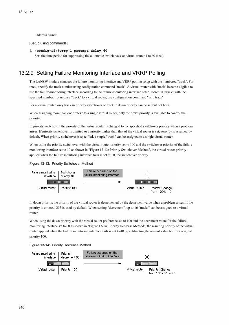
13. VRRP
address owner.
[Setup using commands]
1. (config-if)#vrrp 1 preempt delay 60
Sets the time period for suppressing the automatic switch back on virtual router 1 to 60 (sec.).
13.2.9 Setting Failure Monitoring Interface and VRRP PollingThe LANSW module manages the failure monitoring interface and VRRP polling setup with the numbered "track". For track, specify the track number using configuration command "track". A virtual router with "track" become eligible to use the failure-monitoring interface according to the failure-monitoring interface setup, stored in "track" with the specified number. To assign a "track" to a virtual router, use configuration command "vrrp track".
For a virtual router, only track in priority switchover or track in down priority can be set but not both.
When assigning more than one "track" to a single virtual router, only the down priority is available to control the priority.
In priority switchover, the priority of the virtual router is changed to the specified switchover priority when a problem arises. If priority switchover is omitted or a priority higher than that of the virtual router is set, zero (0) is assumed by default. When priority switchover is specified, a single "track" can be assigned to a single virtual router.
When using the priority switchover with the virtual router priority set to 100 and the switchover priority of the failure monitoring interface set to 10 as shown in "Figure 13-13: Priority Switchover Method", the virtual router priority applied when the failure monitoring interface fails is set to 10, the switchover priority.
Figure 13-13: Priority Switchover Method
In down priority, the priority of the virtual router is decremented by the decrement value when a problem arises. If the priority is omitted, 255 is used by default. When setting "decrement", up to 16 "tracks" can be assigned to a virtual router.
When using the down priority with the virtual router preference set to 100 and the decrement value for the failure monitoring interface set to 60 as shown in "Figure 13-14: Priority Decrease Method", the resulting priority of the virtual router applied when the failure monitoring interface fails is set to 40 by subtracting decrement value 60 from original priority 100.
Figure 13-14: Priority Decrease Method
346

13. VRRP
(1) Setup for "track" monitoring interface failure
[Point of setting]To monitor a specific VLAN interface, execute configuration command "track interface" with "line-protocol" specified.Set the VLAN interface to be monitored in "track".Set "track" on the virtual router for failure monitoring by configuration command "vrrp track".The VLAN interface in charge of monitoring must be assigned with an IP address.
[Setup using commands]
1. (config)#track 20 interface vlan 30 line-protocol
(config)#track 30 interface vlan 31 line-protocol
(config)#track 40 interface vlan 32 line-protocol
• Sets "track 20" as the failure monitoring interface that monitors the state of "vlan 30".• Sets "track 30" as the failure monitoring interface that monitors the state of "vlan 31".• Sets "track 40" as the failure monitoring interface that monitors the state of "vlan 32".
2. (config-if)#vrrp 1 track 20 decrement 60
(config-if)#vrrp 1 track 30 decrement 10
(config-if)#vrrp 1 track 40 decrement 40
Moves to the VLAN configuration mode of the VLAN set up with the virtual router. In this setup, virtual router 1 is assigned with "tracks 20", "30" and "40".• If the failure monitoring interface assigned to "track 20" fails, virtual router 1's priority is decremented by 60.• If the failure monitoring interface assigned to "track 30" fails, virtual router 1's priority is decremented by 10.• If the failure monitoring interface assigned to "track 40" fails, virtual router 1's priority is decremented by 40.
(2) Setup for "track" to be VRRP polled
[Point of setting]If the IP routing has been set up using configuration command "track interface", the "ping" communications between the specified VLAN and the destination specified by configuration command "track ip route" are monitored.Set the VLAN interface for VRRP polling in "track".Set "track" on the virtual router for VRRP polling by configuration command "vrrp track".For failure monitoring through VRRP polling, an IP address must be set for the VLAN interface for VRRP polling, and the route information to the destination must be specified by the track ip route command.
[Setup using commands]
1. (config)#track 50 interface vlan 34 ip routing
(config)#track 51 interface vlan 35 ip routing
(config)#track 52 interface vlan 36 ip routing
• Sets "track 50" as the VRRP polling sending interface that monitors the state of vlan34.• Sets "track 51" as the VRRP polling sending interface that monitors the state of vlan35.• Sets "track 52" as the VRRP polling sending interface that monitors the state of vlan36.
2. (config)#track 50 ip route 192.168.20.1 reachability
(config)#track 51 ip route 192.168.21.1 reachability
(config)#track 52 ip route 192.168.22.1 reachability
347

13. VRRP
• Assigns 192.168.20.1 as the VRRP polling target to "track 50".• Assigns 192.168.21.1 as the VRRP polling target to "track 51".• Assigns 192.168.22.1 as the VRRP polling target to "track 52".
3. (config-if)#vrrp 3 track 50 priority 10
(config-if)#vrrp 4 track 51 decrement 20
(config-if)#vrrp 4 track 52 decrement 50
• Moves to the VLAN configuration mode of the VLAN set up with the virtual router.• Sets up virtual router 3 with "track 50", the priority switchover to control the priorities and switchover priority 10.
If VRRP polling assigned to "track 50" fails, virtual router 3's priority is changed to 10.• Virtual router 4 is assigned with "tracks 51 and 52". Set down priority for priority control. Set the decrement value
to 20 for "track 51". Set the decrement value to 50 for "track 52". If VRRP polling assigned to "track 51" fails, virtual router 4's priority is decremented by 20. If VRRP polling assigned to "track 52" fails, virtual router 4's priority is decremented by 50. If the failure monitoring interface assigned to "tracks 51 and 52" fails, virtual router 4's priority is decremented by 70.
348

13. VRRP
13.3 Operation
13.3.1 List of Operation CommandsThe following table lists the VRRP operation commands:
Table 13-6: List of Operation Commands
13.3.2 Checking Virtual Router SettingUse "show vrrpstatus" to check for the virtual router setup. By executing the command with "detail" parameter, the detailed information on the virtual router is retrieved.
Figure 13-15: Execution Result of "show vrrpstatus" Command
> show vrrpstatus detail interface vlan 10 vrid 1Date 2005/10/15 12:00:00 UTCVLAN0010: VRID 1 Virtual Router IP Address : 192.168.10.1 Virtual MAC Address : 0000.5e00.0101 Current State : MASTER Admin State : enable Priority : 100/100 IP Address Count : 1 Master Router's IP Address : 192.168.10.10 Primary IP Address : 192.168.10.10 Authentication Type : SIMPLE TEXT PASSWORD Authentication Key : ABCDEFG Advertisement Interval : 1 Preempt Mode : ON Preempt Delay : 60(Now Waiting, 30sec. left) Non Preempt swap timer : 0 Accept Mode : OFF Virtual Router Up Time : Tue Dec 20 13:05:53 2005 track 20 VLAN0030 Status : (IF_UP) Down Priority : 60 Target Address: 192.168.20.1 Vrrp Polling Status : (reachable) track 30 VLAN0031 Status : (IF_UP) Down Priority : 10 track 40 VLAN0032 Status : (IF_UP) Down Priority : 40 Target Address: 192.168.40.1 Vrrp Polling Status : (reachable)>
13.3.3 Checking track SettingUse "show track" to check for the "track" setup.
Command Description
show vrrpstatus Displays the virtual router activities.
show vrrpstatus statistics Displays the statistics on the virtual router.
clear vrrpstatus Initializes the statistics on the virtual router.
swap vrrp Reactivates the switch back where the automatic switch back is suppressed.
show track Displays the failure monitoring method setup stored in a "track".
349

13. VRRP
Figure 13-16: Execution Result of "show track" Command
> show track detailDate 2005/10/15 12:00:00 UTCtrack : 20 interface : VLAN0030 Mode : (polling) Target Address : 192.168.20.1 Assigned to : VLAN0010: VRID 1track : 30 interface : VLAN0031 Mode : (interface) Assigned to : VLAN0010: VRID 1track : 40 interface : VLAN0032 Mode : (polling) Target Address : 192.168.40.1 Assigned to : VLAN0010: VRID 1track : 50 interface : VLAN0034 Mode : (polling) Target Address : 192.168.20.1>
13.3.4 Executing Switch BackTo activate the switch back on a virtual router that remains as the backup despite its priority higher than the master because the automatic switch back is suppressed, execute "swap vrrp". Note, however, that executing "swap vrrp" on a virtual router with a lower priority does not make it the master.
350

14uplink-failoverJointly with the SFT (Switch Fault Tolerance) mode of the teaming function provided by the server blade's Intel PROSet as well as the bonding function of Linux, the uplink failover function is used to implement an alternate communication channel when this device's external-device connection port encounters a linkdown because, for example, of a fault in the equipment connected with this device or a break in the cable connecting the equipment. This chapter provides an overview of the uplink failover function and explains setup examples.
14.1 Overview of Uplink Failover
14.2 Note Required When Uplink Failover is Used
14.3 Configuration
14.4 General Description of uplink-failover extended function
14.5 Notice on using the uplink-failover extended function
14.6 Configuration of the uplink failover extended function
14.7 Operation
351

14. uplink-failover
14.1 Overview of Uplink Failover
14.1.1 OverviewJointly with the SFT (Switch Fault Tolerance) mode of the teaming function provided by the server blade's Intel PROSet as well as the bonding function of Linux, the uplink failover function is used to switch communication channels when the external-device connection port encounters a linkdown because of a fault in the neighboring external network equipment.
All server connection port(0/5 - 0/24) is blocked if a linkdown occurs at any of the external-device connection ports that are set for the target of link monitoring (the target of uplink failover). The Intel PROSet's teaming function operating on the server blade OS or the bonding function of Linux is used to continue communication by detecting a block (linkdown) at this server connection port and switching the communication channel to another network interface (NIC) in the team.
The following figure shows an example that provides an overview of the uplink failover function, where NIC A of the server blade is the active system and the NIC B is the standby system.
Figure 14-1: Example of Building Uplink Failover
352
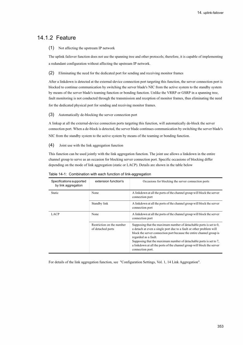
14. uplink-failover
14.1.2 Feature
(1) Not affecting the upstream IP network
The uplink failover function does not use the spanning tree and other protocols; therefore, it is capable of implementing
a redundant configuration without affecting the upstream IP network.
(2) Eliminating the need for the dedicated port for sending and receiving monitor frames
After a linkdown is detected at the external-device connection port targeting this function, the server connection port is blocked to continue communication by switching the server blade's NIC from the active system to the standby system by means of the server blade's teaming function or bonding function. Unlike the VRRP or GSRP in a spanning tree, fault monitoring is not conducted through the transmission and reception of monitor frames, thus eliminating the need
for the dedicated physical port for sending and receiving monitor frames.
(3) Automatically de-blocking the server connection port
A linkup at all the external-device connection ports targeting this function, will automatically de-block the server connection port. When a de-block is detected, the server blade continues communication by switching the server blade's
NIC from the standby system to the active system by means of the teaming or bonding function.
(4) Joint use with the link aggregation function
This function can be used jointly with the link aggregation function. The joint use allows a linkdown in the entire channel group to serve as an occasion for blocking server connection port. Specific occasions of blocking differ depending on the mode of link aggregation (static or LACP). Details are shown in the table below
Table 14-1: Combination with each function of link-aggregation
For details of the link aggregation function, see "Configuration Settings, Vol. 1, 14 Link Aggregation".
Specifications supported by link aggregation
extension function's Occasions for blocking the server connection ports
Static None A linkdown at all the ports of the channel group will block the server connection port
Standby link A linkdown at all the ports of the channel group will block the server connection port
LACP None A linkdown at all the ports of the channel group will block the server connection port
Restriction on the number of detached ports
Supposing that the maximum number of detachable ports is set to 0, a detach at even a single port due to a fault or other problem will block the server connection port because the entire channel group is regarded as a fault.Supposing that the maximum number of detachable ports is set to 7, a linkdown at all the ports of the channel group will block the server connection port.
353

14. uplink-failover
Figure 14-2: Example of Operation During Joint Use with the Link Aggregation Function (Static)
354

14. uplink-failover
14.2 Note Required When Uplink Failover is Used
(1) Configuration using the uplink failover group function
Using this function requires you to install two units of this device in the Compute Blade 2000 / 320. In this case, the server blade's NIC must be set as Preferred Primary in SFT mode by means of the teaming function and as Master/Slave
by means of the bonding function of Linux.
(2) Fault from the uplink failover function
A fault occurring at external network equipment as the target of this function is a linkdown in the physical layer. A fault in which a linkdown cannot be detected in this device's external-device connection port will not block the server
connection port.
(3) Joint use with the link aggregation function• If this function is targeted by the external-device connection port for link aggregation, the server connection port will
not be blocked unless a linkdown occurs at all the ports belonging to the channel group. If, however, the maximum number of detachable ports is set to 0 by using the function of limiting detached ports at LACP, a linkdown occurs at any of the ports and will block the server connection port because the entire channel group is regarded as a fault.
• After the communication channel changes from the active system to the standby system, a link-up occurs at any of the ports belonging to the channel group, thus de-blocking the server connection port. If, however, the maximum number of detachable ports is set to 0 by using the function of limiting detached the server connection port will not
be de-blocked unless a link-up occurs at all the ports belonging to the channel group.
(4) Notes about the link debounce setting for CB320
Port for connecting external devices for this function, link down detection timer (link debounce) the value of more than 5 seconds please.The timer settings link down detection or less than 5 seconds, the default (default timer command link
down detection is 2 seconds), please note that it may become unstable change of the route.
(5) Notes for the feature set uplink-failover• The equipment and uplink-failover spanning tree, GSRP VRRP or not set at the same time.• Port for this and other external devices connected port.Please do not set this feature to connect to the server port.The
book features a set of servers connected to the port, if the down-link connection to the server port to connect to the server block the port.Remove this feature unless you set the server connected to a port in this case, lifting total blockage of the port will not connect to the server.
• If you set this function to external devices that connect the port to set up link aggregation will be set for each port.Belongs to the port channel-group settings to please.
• 10GbpsLAN port switch module 0/3 and 0/4, so you can not use, uplink-failover that please do not.
(6) Precautions required during uplink failover function• Do not enter the "shutdown" command for the external-device connection port specifying this function or the channel
group for link aggregation. Otherwise, the server connection port will be blocked because the result is considered a fault. Note that the server connection port will not be de-blocked unless the "shutdown" command is cancelled. The server connection port will also be blocked if a linkdown occurs when both this device in the active system and the external network equipment, which is connected to the external-device connection port specifying this function in the active system, are switched off or restarted.
• Do not use any of the "restart vlan", "erase configuration", and "copy" commands when making a copy to the running configuration. Do not make a configuration change to the extent that a linkdown occurs at the external-device connection port specifying this function or the channel group for link aggregation. In this case, you must temporarily
355

14. uplink-failover
remove the cable from the external-device connection port. With the server connection port blocked, change the configuration and re-insert the cable into the port for connecting externals.
• Suppose that a storm has occurred at the external-device connection port targeting this function. If the storm is detected and if you set the storm control setting causing the target port to be inactive, any storm during operation will
block the server connection port.
356

14. uplink-failover
14.3 Configuration
14.3.1 List of Configuration CommandsThe following table shows the list of configuration commands for the uplink failover function.
Table 14-2: List of Configuration Commands
14.3.2 Setting Uplink-Failover [Point of setting]
Monitored link (uplink-failover target) is set to the port for connection to external devices.If you set the port for connecting external devices to target the link aggregation, channel-group setting.The equipment and uplink-failover GSRP VRRP or not set at the same time.Spanning tree that you are not at the same time, the spanning tree must be stopped beforehand.uplink-failover to the target port.
[Setup using commands]The following shows an example where the external-device connection port 0/2 is the target of uplink failover. First stop the spanning tree and then make uplink failover the target of port 0/2.
1. (config)# spanning-tree disableStop the spanning tree. This setting is unnecessary if the spanning tree is already stopped.
2. (config)# interface gigabitethernet 0/2The mode moves to the port 0/2 Ethernet interface configuration mode.
3. (config-if)# uplink-failover(config-if)# exitSet port 0/2 as the target of uplink failover.
[Setup using commands] (link aggregation combined for use)Port for connecting external devices 0/3 and 0/4 a static-link-aggrigation, and this channel-group following is an example of combining the features of this case.To stop the first spanning tree, Uplink failover is set for the channel group to which the external-device connection ports 0/3 and 0/4 belong.
1. (config)# spanning-tree disableStop the spanning tree. This setting is unnecessary if the spanning tree is already stopped.
2. (config)# interface range gigabitethernet 0/3-4The mode moves to the Ethernet interface configuration mode at ports 0/3 and 0/4.
3. (config-if-range)# channel-group 10 mode on(config-if-range)# exitAt ports 0/3 and 0/4, the following are set: channel group 10 in the static mode.
4. (config)# interface port-channel 10Shifts to the port channel interface configuration mode of channel group 10.
Command Explanation
uplink-failover Set uplink failover for the external-device connection port. Also set thenumber of the uplink failover group.
357

14. uplink-failover
5. (config-if)# uplink-failover(config-if)# exitSet channel group 10 as the target of uplink failover.
358
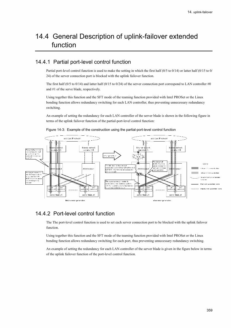
14. uplink-failover
14.4 General Description of uplink-failover extended function
14.4.1 Partial port-level control functionPartial port-level control function is used to make the setting in which the first half (0/5 to 0/14) or latter half (0/15 to 0/24) of the server connection port is blocked with the uplink failover function.
The first half (0/5 to 0/14) and latter half (0/15 to 0/24) of the server connection port correspond to LAN controller #0 and #1 of the serve blade, respectively.
Using together this function and the SFT mode of the teaming function provided with Intel PROSet or the Linux bonding function allows redundancy switching for each LAN controller, thus preventing unnecessary redundancy switching.
An example of setting the redundancy for each LAN controller of the server blade is shown in the following figure in terms of the uplink failover function of the partial-port-level control function:
Figure 14-3: Example of the construction using the partial-port-level control function
14.4.2 Port-level control functionThe The port-level control function is used to set each server connection port to be blocked with the uplink failover function.
Using together this function and the SFT mode of the teaming function provided with Intel PROSet or the Linux bonding function allows redundancy switching for each port, thus preventing unnecessary redundancy switching.
An example of setting the redundancy for each LAN controller of the server blade is given in the figure below in terms of the uplink failover function of the port-level control function.
359
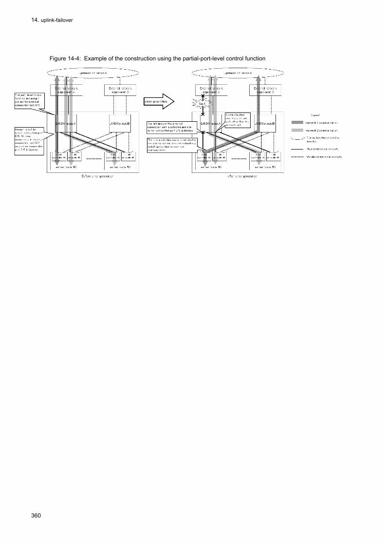
14. uplink-failover
Figure 14-4: Example of the construction using the partial-port-level control function
360

14. uplink-failover
14.5 Notice on using the uplink-failover extended function
(1) Correspondence between the uplink failover extended function and server blade model
The following table lists the server blade models supported with the uplink failover extended function:
Table 14-3: The server blade models supported with the uplink failover extended function:
(Legend) Y : supported , N : not supported
(2) Uplink failover group setting range in the partial-port-level control function
Only uplink failover groups 1 and 2 are valid for the partial-port-level control function.
(3) Switching the uplink failover extended function
The status in which the port-level control function is valid cannot be directly changed to the status in which the partial-port-level control function is valid. To make such a change, execute "no uplink-failover port-control" once and then set "uplink-failover partial-mode."
If the status in which the partial-port-level control function is valid is changed to the status in which the port-level control function is valid, execute "no uplink-failover partial-mode" once and then set "uplink-failover port-control."
(4) About coexistence for all server connection port blockage and for the group port blockage.
When "Uplink-failover for all server connection port blockage" and "Uplink-failover-group for the group port blockage" exist together and are set to this one device,
• The down of the link trouble occurs in the port for the external device connection to which uplink-failover-group is not set:The server connection port is not blockaded.
• The down of the link trouble occurs in the port for the external device connection to which uplink-failover-group is set:
Model server blade model
uplink-failover function
Partial port-level control function
port-level control function
Compute Blade 2000 GVX-BE2LSW1X1GV-BE2LSW1X1-YGVX-BE2LSW2X1GV-BE2LSW2X1-Y
- Y N Y
Compute Blade 320 GGX-BE9LSWM1GG-BE9LSWM1-YGGX-BE9LSWM2AGG-BE9LSWM2A-Y
C51A1 Y N N
C51A2 Y N N
C51x3 Y Y N
C51x4 or later. Y Y Y
Compute Blade 500 GGX-BE3LSW1X1 GV-BE2LSW1X1-Y GGX-BE3LSW2X1 GV-BE2LSW2X1-Y GGX-BE3LSW4X1 GG-BE3LSW4X1-Y
- Y N Y
361

14. uplink-failover
The server connection port set to the same group is blockaded.
Please refer to the following table for the operation when the down of the link is generated in the content of uplink-failover set and the port for the external device connection.
Table 14-4: Setting of uplink-failover and operation at failure
(Legend) Y : Settings , N : No settings , - : Not applicable
Port unit control setting
Uplink-failover setting of port for external device connection
(uplink-failover)
Group setting in server connection port
Operation of server connection port when down of link trouble occurs in port for
external device connection.
(uplink-failover port-control )/(uplink-failover partial-mode
Group setting(uplink-failover-group)
(uplink-failover-group)
N N - N Not blockaded.
N N - Y Not blockaded.
N Y N N All server connection port is blockaded.
N Y N Y All server connection port is blockaded.
N Y Y N All server connection port is blockaded.
N Y Y Y All server connection port is blockaded.
Y N - N Not blockaded.
Y N - Y Not blockaded.
Y Y N N Not blockaded.
Y Y N N Not blockaded.
Y Y Y Y Not blockaded.
Y Y Y Y Only the server connection port set to the same to port group of the down of the link
failure is blockaded.
362

14. uplink-failover
14.6 Configuration of the uplink failover extended function
14.6.1 List of Configuration CommandsThe following table shows the list of configuration commands for the uplink-failover extended function.
Table 14-5: List of Configuration Command
14.6.2 Setting the partial-port-level control function[Point of setting]
The external device connection port is set as the one to be monitored for a link error. Moreover, the partial-port-level control function is used to specify which of the first half (0/5 to 0/14) and the latter half (0/15 to 0/24) of the server connection port is blocked.
[Setup using commands]Given below is an example of setting external device connection port 0/2 as the one to be monitored for a link error. In this example, the partial-port-level control function is used for a port 0/2 error to specify that the first half (0/5 to 0/14) of the server connection port is blocked.First, stop the spanning tree,and then set the port 0/2, as the one to be monitored for a link error. Next, set the partial-port-level control function.
1. (config)# spanning-tree disable
Stop the spanning tree. This setting is unnecessary if the spanning tree is already stopped.
2. (config)# interface gigabitethernet 0/2
The mode moves to the Ethernet interface configuration mode at ports 0/2.
3. (config-if)# uplink-failover uplink-failover-group 1
(config-if)# exit
Port 0/2 is set as the one to be monitored for a link error. Moreover, in this example, the target is set for uplink failover group 1 to specify that the first half (0/5 to 0/14) of the server control port is blocked.
4. (config) # uplink-failover partial-mode
Set the partial-port-level control function.
[Setup using commands] (link aggregation combined for use)An example is given below in which external device connection ports 0/3 and 04 are defined as the static link aggregation and the related channel group and this function are combined for use.In this example, the partial-port-level control function is used to specify that the latter half (0/15 to 0/24) of the server connection port is blocked at error occurrence in the channel group.
Command Explanation
uplink-failover partial-mode Enable partial port unit control to use the uplink failover group function.
uplink-failover port-control Enable port unit control to use the uplink failover group function.
uplink-failover-group The uplink failover group is set for the server connection port.
uplink-failover The uplink failover and uplink failover group number are set for the external device connection port.
363

14. uplink-failover
First, stop the spanning tree, and then set the channel group to which ports 0/3 and 0/4 belong, as the one to be monitored for a link error. Next, set the partial-port-level control function.
1. (config)# spanning-tree disable
Stop the spanning tree. This setting is unnecessary if the spanning tree is already stopped.
2. (config)# interface range gigabitethernet 0/3-4
The mode moves to the Ethernet interface configuration mode at ports 0/3 and 0/4.
3. (config-if-range)# channel-group 10 mode on
(config-if-range)# exit
At ports 0/3 and 0/4, the following are set: channel group 10 in the static mode.
4. (config)# interface port-channel 10
Shifts to the port channel interface configuration mode of channel group 10.
5. (config-if)# uplink-failover uplink-failover-group 2
(config-if)# exit
Set channel group 10 as the one to be monitored for a link error.Moreover, in this example, the target is set for uplink failover group 2 to specify that the latter half (0/15 to 0/24) of the server connection port is blocked.
6. (config)# uplink-failover partial-mode
Set the partial-port-level control function.
14.6.3 Setting the port-level control function[Point of setting]
The external device connection port is set as the one to be monitored for a link error. Moreover, the port-level control function is used to specify which server connection port is blocked.
[Setup using commands]An example is given below in which external device connection port 0/2 is set as the one to be monitored for a link error. First, stop the spanning tree, and then set external device connection port 0/2 as the one to be monitored for a link error. Next, set server connection port 0/5-8 as the one to be blocked with the uplink failover. Finally, set the port-level control function.
1. (config)# spanning-tree disable
Stop the spanning tree. This setting is unnecessary if the spanning tree is already stopped.
2. (config)# interface gigabitethernet 0/2
The mode moves to the Ethernet interface configuration mode at ports 0/2.
3. (config-if)# uplink-failover uplink-failover-group 1
(config-if)# exit
Port 0/2 is set as the one to be monitored for a link error. Moreover, in this example, the target is set for uplink failover group 1 to block the server connection ports belonging to uplink failover group 1 at link error occurrence in port 0/2.
4. (config)# interface range gigabitethernet 0/5-8
The mode moves to the Ethernet interface configuration mode at ports 0/5 to 0/8.
364

14. uplink-failover
5. (config-if-range)# uplink-failover-group 1
(config-if)# exit
Port 0/5-8 is set for uplink failover group 1.
6. (config)# uplink-failover port-control
Set the port-level control function.
[Setup using commands] (link aggregation combined for use)An example is given below in which external device connection ports 0/3 and 0/4 are defined as the static link aggregation and the related channel group and this function are combined for use. First, stop the spanning tree and then set the channel group to which ports 0/3 and 0/4 belong as the one to be monitored for a link error. Next, set the server connection port 0/5-8 as the one to be blocked for a link with the uplink failover. Finally, set the port-level control function.
1. (config)# spanning-tree disable
Stop the spanning tree. This setting is unnecessary if the spanning tree is already stopped.
2. (config)# interface range gigabitethernet 0/3-4
The mode moves to the Ethernet interface configuration mode at ports 0/3 to 0/4.
3. (config-if-range)# channel-group 10 mode on
(config-if-range)# exit
At ports 0/3 and 0/4, the following are set: channel group 10 in the static mode.
4. (config)# interface port-channel 10
Shifts to the port channel interface configuration mode of channel group 10.
5. (config-if)# uplink-failover uplink-failover-group 1
(config-if)# exit
Channel-group 10 is set as the one to be monitored for a link error. Moreover, in this example, the target is set for uplink failover group 1 to block the server connection ports belonging to uplink failover group 1 at link error occurrence in channel group 10.
6. (config)# interface range gigabitethernet 0/5-8
The mode moves to the Ethernet interface configuration mode at ports 0/5 to 0/8.
7. (config-if-range)# uplink-failover-group 1
(config-if)# exit
Port 0/5-8 is set for uplink failover group 1.
8. (config)# uplink-failover port-control
Set the port-level control function.
14.6.4 Example of setting uplink-failover function when load-balancing is composed
[Point of setting]
365

14. uplink-failover
The total throughput of the port for the external device connection can be reduced by half by dividing the communication route of the server blade of ten braids or less installed in Compute Blade 2000 / 320 equally with this two devices two. When uplink-failover is set by such a load-balancing composition, uplink-failover is set to this two devices. "Figure 12-5 Example of constructing uplink-failover when load-balancing is composed" is an example of constructing the load-balancing composition by using LAN controller#0 of server blade. To relay it by way of the LANSW module A, server blade # 0 and server blade # 2 make each LAN1 primary.
Figure 14-5: Example of constructing uplink-failover when load-balancing is composed
[Setup using commands]The example of setting the uplink-failover-group function in the load-balancing composition of "Figure 12-5 Example of constructing uplink-failover when load-balancing is composed" is shown below. The uplink-failover-group number is set to the server connection port connected with LAN controller of primary of each server blade. In the server connection port connected with LAN controller of secondary, the setting of the uplink-failover-group number is unnecessary.
<Example of setting the LANSW module A>Uplink-failover-group1 is set to port 0/1 and server connection port 0/5 for the external device connection, and uplink-failover-group2 is set to port 0/3 for the external device connection and server connection port 0/7.
1. (config)# spanning-tree disable
(config)# uplink-failover port-control
To stop the spanning tree, and to use the uplink-failover-group function, the port unit control is effectively done.
2. (config)# interface gigabitethernet 0/1
(config-if)# uplink-failover uplink-failover-group 1
(config-if)# link debounce time 5000
(config-if)# switchport mode access
(config-if)# switchport access vlan 10
366

14. uplink-failover
(config-if)# exit
Uplink-failover-group 1, VLAN 10, and the down of the link detection timer of 5000 milliseconds are set to port 0/1 for the external device connection.
3. (config)# interface gigabitethernet 0/5
(config-if)# uplink-failover-group 1
(config-if)# switchport mode access
(config-if)# switchport access vlan 10
(config-if)# exit
Uplink-failover-group 1 and VLAN 10 are set to server connection port 0/5.
4. (config)# interface gigabitethernet 0/15
(config-if)# switchport mode access
(config-if)# switchport access vlan 10
(config-if)# exit
VLAN 10 is set to server connection port 0/15.
5. (config)# interface gigabitethernet 0/3
(config-if)# uplink-failover uplink-failover-group 2
(config-if)# link debounce time 5000
(config-if)# switchport mode access
(config-if)# switchport access vlan 30
(config-if)# exit
Uplink-failover-group 2, VLAN 30, and the down of the link detection timer of 5000 milliseconds are set to port 0/3 for the external device connection.
6. (config)# interface gigabitethernet 0/7
(config-if)# uplink-failover-group 2
(config-if)# switchport mode access
(config-if)# switchport access vlan 30
(config-if)# exit
Uplink-failover-group2 and VLAN 30 are set to server connection port 0/7.
7. (config)# interface gigabitethernet 0/17
(config-if)# switchport mode access
(config-if)# switchport access vlan 30
(config-if)# exit
VLAN 30 is set to server connection port 0/17.
8. (config)# interface gigabitethernet 0/2
(config-if)# switchport mode access
(config-if)# switchport access vlan 20
(config-if)# exit
(config)# interface gigabitethernet 0/6
(config-if)# switchport mode access
(config-if)# switchport access vlan 20
(config-if)# exit
(config)# interface gigabitethernet 0/16
(config-if)# switchport mode access
(config-if)# switchport access vlan 20
367

14. uplink-failover
(config-if)# exit
VLAN 20 is set to port 0/2 for the external device connection, server connection port 0/6, and 0/16.
9. (config)# interface gigabitethernet 0/4
(config-if)# switchport mode access
(config-if)# switchport access vlan 40
(config-if)# exit
(config)# interface gigabitethernet 0/8
(config-if)# switchport mode access
(config-if)# switchport access vlan 40
(config-if)# exit
(config)# interface gigabitethernet 0/18
(config-if)# switchport mode access
(config-if)# switchport access vlan 40
(config-if)# exit
VLAN 40 is set to port 0/4 for the external device connection, server connection port 0/8, and 0/18.
<Example of setting the LANSW module B>Uplink-failover-group3 is set to port 0/2 and server connection port 0/6 for the external device connection, and uplink-failover-group4 is set to port 0/4 for the external device connection and server connection port 0/8.
1. (config)# spanning-tree disable
(config)# uplink-failover port-control
To stop the spanning tree, and to use the uplink-failover-group function, the port unit control is effectively done.
2. (config)# interface gigabitethernet 0/2
(config-if)# uplink-failover uplink-failover-group 3
(config-if)# link debounce time 5000
(config-if)# switchport mode access
(config-if)# switchport access vlan 20
(config-if)# exit
Uplink-failover-group 3, VLAN 20, and the down of the link detection timer of 5000 milliseconds are set to port 0/2 for the external device connection.
3. (config)# interface gigabitethernet 0/6
(config-if)# uplink-failover-group 3
(config-if)# switchport mode access
(config-if)# switchport access vlan 20
(config-if)# exit
Uplink-failover-group 3 and VLAN 20 are set to server connection port 0/6.
4. (config)# interface gigabitethernet 0/16
(config-if)# switchport mode access
(config-if)# switchport access vlan 20
(config-if)# exit
VLAN 20 is set to server connection port 0/16.
5. (config)# interface gigabitethernet 0/4
(config-if)# uplink-failover uplink-failover-group 4
(config-if)# link debounce time 5000
368

14. uplink-failover
(config-if)# switchport mode access
(config-if)# switchport access vlan 40
(config-if)# exit
Uplink-failover-group 4, VLAN 40, and the down of the link detection timer of 5000 milliseconds are set to port 0/4 for the external device connection.
6. (config)# interface gigabitethernet 0/8
(config-if)# uplink-failover-group 4
(config-if)# switchport mode access
(config-if)# switchport access vlan 40
(config-if)# exit
Uplink-failover-group 4 and VLAN 40 are set to server connection port 0/8.
7. (config)# interface gigabitethernet 0/18
(config-if)# switchport mode access
(config-if)# switchport access vlan 40
(config-if)# exit
VLAN 40 is set to server connection port 0/18.
8. (config)# interface gigabitethernet 0/1
(config-if)# switchport mode access
(config-if)# switchport access vlan 10
(config-if)# exit
(config)# interface gigabitethernet 0/5
(config-if)# switchport mode access
(config-if)# switchport access vlan 10
(config-if)# exit
(config)# interface gigabitethernet 0/15
(config-if)# switchport mode access
(config-if)# switchport access vlan 10
(config-if)# exit
VLAN 10 is set to port 0/1 for the external device connection, server connection port 0/5, and 0/15.
9. (config)# interface gigabitethernet 0/3
(config-if)# switchport mode access
(config-if)# switchport access vlan 30
(config-if)# exit
(config)# interface gigabitethernet 0/7
(config-if)# switchport mode access
(config-if)# switchport access vlan 30
(config-if)# exit
(config)# interface gigabitethernet 0/17
(config-if)# switchport mode access
(config-if)# switchport access vlan 30
(config-if)# exit
VLAN 30 is set to port 0/3 for the external device connection, server connection port 0/7, and 0/17.
369

14. uplink-failover
14.7 Operation
14.7.1 List of Operation CommandsThe following table shows the list of operation commands for uplink failover.
Table 14-6: List of Operation Commands
14.7.2 List of Operation CommandsThe following table shows the list of operation commands for uplink failover.
Figure 14-6: Result of Executing the "show uplink-failover" Command
When uplink failover is set> show uplink-failoverDate 2007/02/22 22:34:06 UTC Uplink-failover Status:On Uplink Status Port 0/2 :disable ChGr 10 :upSERDES Status:inactive>
When uplink failover is not set> show uplink-failoverDate 2007/02/22 22:34:06 UTCUplink-failover Status:Off>
When partial-port-level control function is set>show uplink-failoverDate 2007/10/29 11:33:51 UTCUplink-failover Status:OnUplink StatusPort 0/2 :active up uplink-failover-group 1ChGr 10 :up uplink-failover-group 2SERDES Status:partial-modeuplink-failover-group 1interface Port 0/5 : active up:interface Port 0/14 : active upuplink-failover-group 2interface Port 0/15 : active upinterface Port 0/16 : active up:interface Port 0/24 : active up>
Command Explanation
show uplink-failover The operation status for uplink failover is displayed
370

14. uplink-failover
When port-level control function is set> show uplink-failoverDate 2007/10/29 11:33:51 UTCUplink-failover Status:OnUplink StatusPort 0/2 :active up uplink-failover-group 1ChGr 10 :up uplink-failover-group 2SERDES Status:port-controluplink-failover-group 1interface Port 0/5 : active up:interface Port 0/14 : active upuplink-failover-group 2interface Port 0/15 : active upinterface Port 0/16 : active up:interface Port 0/24 : active up>
371

14. uplink-failover
372

15Uplink RedundancyUplink redundancy provides redundancy for ports used for uplink; that is, one of the paired ports is used for communication, and the other stands by in case a failure occurs. For uplink ports, you can specify physical ports or aggregated link ports.This chapter describes uplink redundancy and its use.
15.1 Description
15.2 Configuration
15.3 Operation
373

15. Uplink Redundancy
15.1 Description
15.1.1 OverviewUplink redundancy enables duplexed uplink ports on the Switch. If a link failure occurs during communication, the standby port takes over for the current port to continue communication with upstream switches. By using uplink redundancy, you can create redundant uplink ports without using complex protocols such as the Spanning Tree Protocol. A pair of redundant ports is called an uplink port pair.
The following figure shows the basic configuration of uplink redundancy.
Figure 15-1: Basic configuration of uplink redundancy
When you use uplink redundancy in this configuration, if the link between the Switch and upstream switch A fails, the link between the Switch and upstream switch B can take over to continue communication.
15.1.2 Supported specificationsThe following table describes the specifications supported for uplink redundancy.
Table 15-1: Specifications supported for uplink redundancy
Item Support or specified value
Applicable interfaces Physical ports Y
Link aggregation Y
Number of uplink ports 25
Number of interfaces that can be configured for one uplink port pair 2
Automatic active-port preemption to the primary port Y
Suppression of automatic active-port preemption to the primary port Y
Command for changing the active port Y
Sending and receiving of flush control frames when the active port is changed Y
MAC address updating when the active port is changed Y
Active port locking at startup Y
Private MIB and private traps Y
374

15. Uplink Redundancy
Legend Y: Supported
15.1.3 Overview of uplink redundancy operationUplink redundancy provides redundancy by using a pair of ports or bundles of ports (aggregated link ports). This pair of ports is called an uplink port pair. An uplink port pair consists of a primary port that performs communication during normal operation and a secondary port that takes over as the primary port in case of a failure. You can configure these ports by using configuration commands.
The primary port and the secondary port do not need to have the same bandwidth or consist of the same number of ports. For example, you can specify a 10-Gigabit Ethernet port as the primary port and a link aggregation group consisting of five 1-Gigabit Ethernet ports as the secondary port.
In the uplink port pair, the port that is currently performing communication is called the active port. The other port is called the standby port, and it stands ready to take over as the active port if the active port fails so that communication can continue.
The ports of the uplink port pair must belong to the same VLAN and have the same settings. In addition, the ports used for an uplink port pair cannot be used as another uplink port pair.
The following figure provides an overview of uplink redundancy operation.
375

15. Uplink Redundancy
Figure 15-2: Operation overview of uplink redundancy
Normal operationCommunication with upstream switches is possible via the primary port on the Switch. The secondary port on the Switch is not communicating.
If the primary port failsIf the primary port link goes down, the Switch switches the active port to the secondary port and uses it to continue communication with upstream switches. This action is called a switchover. At this time, the secondary port, which is now the active port, sends a special control frame called a flush control frame or an MAC address update frame to the upstream switches. When the upstream switches receive either frame, they update their MAC address tables and immediately resume communication.
376

15. Uplink Redundancy
When the primary port is restoredWhen the primary port link is enabled and the port is standing by, you can use automatic preemption or execute the appropriate operation command on the Switch to switch the active port to the primary port. This action is called preemption.As in a switchover, the active port sends a flush control frame or an MAC address update frame to immediately resume communication with the upstream switches.
15.1.4 Switchover and preemptionSwitchover and preemption change the port that performs communication. Switchover or preemption is triggered by one of the following events when the partner port of the active port is the standby port:
• When a failure occurs on the active port• When the automatic preemption wait time has expired• When a user enters an operation command to change the active port
When switchover or preemption occurs, all the MAC addresses learned on the previous active port are cleared, and the new active port starts communication. When the uplink port pair is configured to send flush control frames or MAC address update frames, the new active port sends either type of frame when switchover or preemption occurs.
The following figure illustrates switchover.
Figure 15-3: Switchover
15.1.5 Automatic preemptionIf the primary port fails, the secondary port replaces the primary port as the active port. Automatic preemption automatically restores the primary port as the active port when it is restored after a failure. You can specify from 0
377
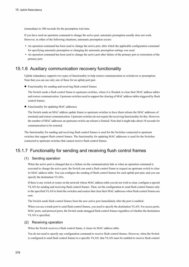
15. Uplink Redundancy
(immediate) to 300 seconds for the preemption wait time.
If you have used an operation command to change the active port, automatic preemption usually does not work. However, in either of the following situations, automatic preemption occurs:
• An operation command has been used to change the active port, after which the applicable configuration command for specifying automatic preemption or changing the automatic preemption settings was used.
• An operation command has been used to change the active port after failure of the primary port or restoration of the primary port.
15.1.6 Auxiliary communication recovery functionalityUplink redundancy supports two types of functionality to help restore communication at switchover or preemption. Note that you can use only one of these for an uplink port pair.
Functionality for sending and receiving flush control frames
The Switch sends a flush control frame to upstream switches, where it is flooded, to clear their MAC address tables and restore communication. Upstream switches need to support the clearing of MAC address tables triggered by flush control frames.
Functionality for updating MAC addresses
The Switch sends an MAC address update frame to upstream switches to have them relearn the MAC addresses of terminals and restore communication. Upstream switches do not require the receiving functionality for this. However, the number of MAC addresses an upstream switch can relearn is limited. Note that it might take about 10 seconds for
communication to be restored.
The functionality for sending and receiving flush control frames is used for the Switches connected to upstream switches that support flush control frames. The functionality for updating MAC addresses is used for the Switches connected to upstream switches that cannot receive flush control frames.
15.1.7 Functionality for sending and receiving flush control frames
(1) Sending operationWhen the active port is changed due to a failure on the communication link or when an operation command is executed to change the active port, the Switch can send a flush control frame to request an upstream switch to clear its MAC address table. You can configure the sending of flush control frames for each uplink port pair, and you can specify the destination VLANs.
If there is any switch or router on the network whose MAC address table you do not wish to clear, configure a special VLAN for sending and receiving flush control frames. Then, set the configuration to send flush control frames only to the specified VLAN to limit the switches and routers that clear their MAC addresses when flush control frames are sent.
The Switch sends flush control frames from the new active port immediately after the port is enabled.
When you use a trunk port to send flush control frames, you need to specify the destination VLAN. For access ports, MAC ports, and protocol ports, the Switch sends untagged flush control frames regardless of whether the destination VLAN is specified.
(2) Receiving operationWhen the Switch receives a flush control frame, it clears its MAC address table.
You do not need to specify any configuration command to receive flush control frames. However, when the Switch is configured to send flush control frames to a specific VLAN, that VLAN must be enabled to receive flush control
378

15. Uplink Redundancy
frames.
The following figure shows the difference in switchover operation according to the use of flush control frames.
379

15. Uplink Redundancy
Figure 15-4: Difference in switchover operation according to flush control frame use
Normal operationThe primary port on the Switch performs communication. Upstream switches learn the MAC address of the user terminal via the current communication path.
If the primary port fails (when flush control frames are not sent)If the Switch is not configured to send flush control frames, although the secondary port is now active, upstream switch B retains the MAC address of the user terminal on the previous port. Therefore, communication is not restored until the MAC address learned by upstream switch B is erased or the user terminal sends traffic to upstream switch B.
If the primary port fails (when flush control frames are sent)
380

15. Uplink Redundancy
If the Switch is configured to send flush control frames, it sends a flush control frame to request that upstream switch B clear its MAC address table as soon as the secondary port becomes active. Therefore, communication can be restored immediately.
15.1.8 Functionality for updating MAC addresses
(1) Sending operation
When the active port is changed due to a failure on the communication link or when an operation command is executed to change the active port, the Switch can send an MAC address update frame to have an upstream switch relearn the MAC address of a terminal. The MAC address update frame has the following features:
• The MAC address update frame is a multicast frame.• You specify the MAC address to be learned by upstream switches as the source MAC address.• Upstream switches do not need a special receiving functionality.
You can configure the functionality for updating MAC addresses for each uplink port pair. You can also specify VLANs to which MAC address update frames are not to be sent.
When you use this functionality, the maximum number of recommended entries in a MAC address table is 16384. If you exceed the recommended value, it might take more time before communication is restored, or the response of operation commands for uplink redundancy might be slow.
The following figure shows the difference in switchover operation according to the use of MAC address update frames.
381
15. Uplink Redundancy
Figure 15-5: Difference in the switchover operation according to MAC address update frame use
Normal operationThe primary port on the Switch performs communication. Upstream switches learn the MAC address of the user terminal via the current communication path.
If the primary port fails (when MAC address update frames are not sent)If the Switch is not configured to send MAC address update frames, although the secondary port is now active, upstream switch B retains the MAC address of the user terminal on the previous port. Therefore, communication is not restored until the MAC address learned by upstream switch B is erased or the user terminal sends traffic to upstream switch B.
If the primary port fails (when MAC address update frames are sent)
382

15. Uplink Redundancy
If the Switch is configured to send MAC address update frames, it sends an MAC address update frame to request that upstream switch B change the port on which it learns the MAC address of the user terminal as soon as the secondary port becomes active. Therefore, communication can be restored immediately.
The following table describes the specifications of the functionality for updating MAC addresses.
Table 15-2: Specifications of the functionality for updating MAC addresses
#: Set in the configuration
(2) Receiving operation
As with other frames, when the Switch relays MAC address update frames, it learns the source MAC addresses contained in the frames and registers them in its MAC address table. For details, see 16 MAC Address Learning in the
manual Configuration Guide Vol. 1 .
15.1.9 Active port locking at switch startupUse active port locking at Switch startup if you want to always start communication on the primary port when the Switch starts. When this functionality is enabled on a Switch, communication via the uplink port pair does not start even if the secondary port is enabled at startup. Instead, communication starts only when the primary port is enabled.
Operation proceeds as usual when communication has started on the primary port. If the primary port fails or a user executes the applicable operation command, the secondary port takes over for the primary port. If the primary port link is disabled at switch startup because, for example, an upstream switch on the primary port side has failed, execute the appropriate operation command to use the secondary port to start communication.
The following figure shows operation when active port locking at switch startup is enabled.
Item Description
Unit for ports that send MAC address update frames
Uplink port pair
Sending port Enabled active port
Number of times frames are sent# 1 to 3 (times)
MAC address entries to be sent Entries must concurrently satisfy the following conditions:
• They must be entries that are learned on the VLANs containing the appli-cable uplink port pair. These entries do not include entries learned on the VLANs not subject to the sending MAC address update frames as speci-fied in the applicable configuration.
• They must be entries that are learned on ports other than the applicable uplink port pair.
Types of MAC address entries to be sent • Dynamic entries• Static entries• Entries authenticated by IEEE 802.1X• Entries authenticated by Web-based authentication• Entries authenticated by MAC-based authentication• Switch MAC addresses• MAC addresses of VLAN interfaces• Virtual MAC address
Maximum number of MAC address entries to be sent
3000 entries.If the number of entries to be sent exceeds 3000, only 3000 entries are sent and an operation log message indicating that the capacity limit has been exceeded is output.
Sending rate 300 pps at maximum
383

15. Uplink Redundancy
Figure 15-6: Operation when active port locking at switch startup is enabled
15.1.10 Notes on using uplink redundancy
(1) Notes on use with other functionality
The following table describes the functionality that cannot be used or can only partially be used with uplink redundancy.
Table 15-3: Use with other functionality
Legend n/a: Not applicable
Functionality Available Remarks
VLAN tunneling Partially Cannot be used for uplink port pairs
Tag translation Partially
MAC address learning Partially Static entries cannot be used for uplink port pairs.
Spanning Tree Protocol No n/a
GSRP No n/a
Ring Protocol Partially Cannot be used for uplink port pairs
Layer 2 Authentication Partially Cannot be used for uplink port pairs
384

15. Uplink Redundancy
(2) Using the functionality for sending and receiving flush control frames
Check whether the upstream switches support the reception of flush control frames sent by uplink redundancy.
If the upstream switches do not support the flush control frame functionality, the MAC address tables on the switches will not be cleared even if flush control frames are sent from the Switch. As a result, it might take some time before communication is restored.
(3) Sending flush control frames on trunk ports
If you want to send flush control frames on a trunk port, make sure you specify the destination VLAN. If you do not specify the destination VLAN, untagged flush control frames are sent only when a native VLAN exists. If no native VLAN is configured, flush control frames are not sent.
(4) Specifying configuration commands that disable VLANs
When you specify one of the configuration commands below related to uplink redundancy for the first time on the Switch, all VLANs temporarily go down. Therefore, before you create a network that uses uplink redundancy, we recommend that you set the following configuration commands beforehand.
• switchport backup flush-request• switchport backup interface• switchport backup mac-address-table update exclude-vlan
• switchport backup mac-address-table update transmit
385

15. Uplink Redundancy
15.2 Configuration
15.2.1 List of Configuration CommandsThe following table describes the commands used to configure uplink redundancy.
Table 15-4: List of configuration commands
15.2.2 Configuring uplink redundancyThe figure below describes an example uplink redundancy configuration. This subsection describes how to configure uplink redundancy based on this example.
Figure 15-7: Example of an uplink redundancy configuration
On the Switch, this configuration configures port 0/1 as the primary port and port 0/2 as the secondary port. It also specifies 60 seconds as the automatic preemption wait time and enables the sending of flush control frames.
(1) Configuring uplink redundancy
Points to noteConfigures port 0/1 as the primary port and port 0/2 as the secondary port. Specifies 60 seconds as the automatic preemption wait time. You need to disable the Spanning Tree Protocol before you configure uplink redundancy.
Command name Description
switchport backup flush-request transmit Enables the sending of flush control frames to upstream switches at switchover or preemption to request that the upstream switches clear their MAC address tables.
switchport backup interface Allows you to specify a primary port and secondary port for uplink redundancy and define them as an uplink port pair. You can also specify the automatic preemption wait time to enable automatic preemption.
switchport backup mac-address-table update exclude-vlan
Specifies a VLAN as one to which MAC address update frames are not to be sent.
switchport backup mac-address-table update transmit
Enables the sending of MAC address update frames to upstream switches at switchover or preemption to request that the upstream switches update their MAC address tables.
switchport-backup startup-active-port-selection
Enables active port locking at switch startup.
386
15. Uplink Redundancy
Configures the sending of flush control frames on the primary port.
Command examples
1. (config)# spanning-tree disable
Disables the Spanning Tree Protocol.
2. (config)# interface gigabitethernet 0/1
(config-if)# switchport backup interface gigabitethernet 0/2 preemption-delay
60
Enters configuration mode for port 0/1.Sets port 0/2 as the secondary port in the configuration mode for port 0/1, which is the primary port, and sets 60 seconds as the automatic preemption wait time.
3. (config-if)# switchport backup flush-request transmit
(config-if)# exit
Enables the sending of flush control frames.
[Note]
• Before you configure uplink redundancy, the network is in a loop configuration. Shut down the primary port or the secondary port to prevent loops, and then set up the configuration.
• If you want to specify the ports in a link aggregation group as the primary port, use a port channel interface. You cannot use an Ethernet interface in a link aggregation group as the primary port.
387

15. Uplink Redundancy
15.3 Operation
15.3.1 List of operation commandsThe following table describes the operation commands for uplink redundancy.
Table 15-5: List of operation commands
15.3.2 Displaying the status of uplink redundancyYou can display the destination VLANs for flush control frames and the status of the primary and secondary ports.
Figure 15-8: Result of executing show switchport-backup
> show switchport-backupDate 20XX/09/04 16:48:07 UTCstartup active port selection: primary onlySwitchport Backup pairs Preemption Flush Primary Status Secondary Status Delay Rest VLAN Update Port 0/1 Forwarding Port 0/24 Blocking - - 4094 - Port 0/10 Down ChGr 4 Forwarding - - - 1*Port 0/11 Down Port 0/15 Blocking - - 10 -*Port 0/20 Down Port 0/21 Down - - 200 -> • Status column
Forwarding indicates the active port, and Blocking indicates the standby port.
15.3.3 Manually changing the active portTo change the active port, use the set switchport-backup active command.
This command is effective only when the specified port is the standby port.
Figure 15-9: Result of executing set switchport-backup active
> set switchport-backup active port 0/1Are you sure to change the forwarding port to specified port? (y/n): y>
Command name Description
show switchport-backup Displays information about uplink redundancy.
show switchport-backup statistics Displays statistics pertaining to uplink redundancy.
clear switchport-backup statistics Deletes statistics pertaining to uplink redundancy.
set switchport-backup active Specifies a new active port.
restart uplink-redundant Restarts the uplink redundancy program.
dump protocols uplink-redundant Outputs dump data regarding uplink redundancy to a file.
388

Part 6 High Reliability Function Through Network Failure Detection
16Storm ControlThe storm control restricts the forwarding bandwidth for flooding frames. This chapter describes the storm control and how to use it.
16.1 Storm Control Overview
16.2 Configuration
389

16. Storm Control
16.1 Storm Control Overview
16.1.1 Outline of Storm ControlIf a loop presents in layer 2 network, broadcast frames may be infinitely forwarded between switches and the network and connected devices can be imposed with excessive loadings. This phenomenon is called "Broadcast storm" and must be avoided on layer 2 networks. "Multicast storm" and "Unicast storm" where multicast and unicast frames are infinitely forwarded respectively must be avoided as well.
The storm control makes switches restrict the bandwidth to flood frames to reduce the influence on the devices connected to the network.
The LANSW module allows to set up the maximum frames that are received per second as the threshold, and discards frames excess in the value. The threshold is available by "broadcast," "multicast," or "unicast" frames, and must be set up for each type of frames.
If the number of received frames exceeds the threshold, the port can be blocked or the private trap or log message can be output.
No operation command is provided for the storm control.
16.1.2 Notes on Using Storm Control
(1) Handling of unicast frames
On the LANSW module, target frames are different between unicast storm detection and frame discarding. Unicast storm is detected for all of the received unicast frames. Frame discarding is only applied to unicast frames that are flooded because the destination MAC address is not registered in the MAC address table.
(2) Storm detection and recovery detection
On the LANSW module, occurrence of storm is identified when the number of frames received in a second exceeds the threshold set in the configuration. When the number of frames in a second is below the threshold for 30 seconds after occurrence of storm, recovery from storm is identified.
If the port is blocked upon occurrence of storm, the port does not receive frames any more. Therefore, recovery from storm cannot be detected. If the port is blocked upon occurrence of storm, ensure recovery from storm by another means such as network monitoring system other than the LANSW module.
390

16. Storm Control
16.2 Configuration
16.2.1 List of Configuration CommandsThe following table lists the storm control configuration commands:
Table 16-1: List of Configuration Commands
16.2.2 Setting Storm ControlRestricting broadcast framesTo restrict the broadcast frames, set up the maximum number of broadcast frames to receive via the Ethernet interface as the threshold. Since broadcast frames may include ARP packets, which are must for communications, a loose-fitted threshold must be set up putting the number of frames normally used in mind.
Restricting multicast framesTo restrict the multicast frames, set up the maximum number of multicast frames to receive via the Ethernet interface as the threshold. Since multicast frames may include IPv4, IPv6 or OSPF packets, which are must for communications, a loose-fitted threshold must be set up putting the number of frames normally used in mind.
Restricting unicast framesTo restrict the unicast storm, set up the maximum number of unicast frames to receive via the Ethernet interface as the threshold. For the threshold, set a value with an allowance in consideration of the number of frames that are normally used.On the LANSW module, the total number of received unicast frames is used to detect unicast storm. Frames that are not relayed but discarded are only the unicast frames that are flooded because the destination MAC address is not registered in the MAC address table. Especially, if port blocking is to be specified upon storm detection, the threshold to be set must have a sufficient allowance so that the storm will not be detected among the frames that are normally used.
Action upon storm detectionThe action of the LANSW module against storm detection is set. A combination of port blocking, private trap sending, and log message can be selected for each port.• Port blocking
When storm is detected, the port is deactivated. After recovery from a storm, use the activate command to activate the port again.
• Private trap sendingWhen a storm or recovery from the storm is detected, private trap is sent for notification.
• Log message outputWhen a storm or recovery from the storm is detected, log message is output for notification. However, the message upon port blocking is always output.
[Point of setting]This control is only available to the Ethernet interface.When a storm occurs, the port is blocked.
[Setup using commands]
1. (config)# interface gigabitethernet 0/3
Command Description
storm-control Sets the threshold for storm control. Also, action against storm detection can be set.
391

16. Storm Control
(config-if)# storm-control broadcast level pps 50
Sets the threshold for broadcast frames to 50.
2. (config-if)# storm-control mutlicast level pps 500
Sets the threshold for multicast frames to 500.
3. (config-if)# storm-control unicast level pps 1000
Sets the threshold for unicast frames to 1000.
4. (config-if)# storm-control action inactivate
When a storm is detected, the port is deactivated.
392

17 IEEE802.3ah/UDLDThe IEEE802.3ah/UDLD function detects a one-way link failure and prevents occurrence of the resulting network failure.This chapter outlines the IEEE802.3ah/UDLD function and explains how to use it.
17.1 IEEE802.3ah/UDLD Overview
17.2 Configuration
17.3 Operation
393

17. IEEE802.3ah/UDLD
17.1 IEEE802.3ah/UDLD Overview
17.1.1 Outline of IEEE802.3ah/UDLDUDLD (Uni-Directional Link Detection) is a function that detects a one-way link failure.
If a one-way link failure occurs, sending is enabled but receiving is disabled on one system, while receiving is enabled but sending is disabled on the other system. Malfunction occurs on the upper layer protocol and various failures occur on the network. Well-known examples include loop occurrence in the spanning tree and frame loss in link aggregation. These failures can be prevented by deactivating the corresponding port when a one-way link failure is detected.
The OAM (Operations, Administration, and Maintenance) protocol (hereinafter referred to as IEEE802.3ah/OAM) positioned as part of the slow protocol in IEEE802.3ah (Ethernet in the First Mile) verifies frame reachability to the remote system by constantly exchanging OAM status information between the remote system and local system so as to monitor the two-way link status. The LANSW module uses the IEEE802.3ah/OAM function to monitor the two-way link status. If the status cannot be verified, the LANSW module enables the UDLD function by detecting a one-way link failure.
The IEEE802.3ah/OAM protocol provides the concepts of the Active mode and Passive mode. the Active mode side starts sending a control frame and the Passive mode side does not send a control frame until it receives the control frame. On the LANSW module, the IEEE802.3ah/OAM function is enabled by the factory default and all ports run in the Passive mode.
By setting configuration command "efmoam active udld" on the port of a system that is connected via the Ethernet cable, a one-way link failure can be detected. For correct detection of a one-way link failure, the IEEE802.3ah/OAM function must be enabled on the port of the other system. If a one-way link failure is detected on the port for which the "efmoam active udld" command is set, deactivating the corresponding port results in link-down on the port of the remote system and operation on corresponding ports of both connected systems is stopped.
17.1.2 Support SpecificationsThe IEEE802.3ah/UDLD function supports the IEEE802.3ah/OAM function as shown in the table below.
Table 17-1: IEEE802.3ah OAMPDU Supported by IEEE802.3ah/UDLD
(Legend) Y: Supported N: Not supported
Name Description Support
Information Sends the OAM status information to the remote system. Y
Event Notification Sends the "Link Event" warning to the remote system. N
Variable Request Request the remote system for the MIB variable. N
Variable Response Sends the requested MIB variable. N
Loopback Control Controls the Loopback status of the remote system. N
Organization Specific For function extension N
394

17. IEEE802.3ah/UDLD
17.1.3 Notes on Using IEEE802.3ah/UDLD
(1) If the system not supporting the IEEE802.3ah/OAM function is connected to another system with the IEEE802.3ah/UDLD function set
General switches do no relay the control frame used by the IEEE802.3ah/OAM function. Therefore, information cannot be exchanged between the systems. A one-way link failure is detected on the port for which configuration command "efmoam active udld" is set. The IEEE802.3ah/UDLD function cannot be operated.
(2) If a relay unit such as media converter is connected between the systems for which the IEEE802.3ah/UDLD function is set
If a media converter that does not automatically disconnect the link when the other link is disconnected is connected between the systems, deviation in recognition of the link status occurs between the systems. Therefore, a one-way link failure is detected even though the remote system is not running on the port for which the command "efmoam active udld" is set. For recovery, both systems must synchronize with each other, which may make operation difficult. Use a media converter that automatically disconnects the link when the other link is disconnected.
(3) Connection to other vendors' UDLD function
Since each vendor originally implements the UDLD function, the IEEE802.3ah/UDLD function on the LANSW module and the UDLD function on the system of another vendor cannot be mutually connected.
395

17. IEEE802.3ah/UDLD
17.2 Configuration
17.2.1 List of Configuration CommandsThe following table provides a list of IEEE802.3ah/UDLD configuration commands:
Table 17-2: List of Configuration Commands
17.2.2 Setting IEEE802.3ah/UDLD
(1) Setting IEEE802.3ah/UDLD function
[Point of setting]To operate the IEEE802.3ah/UDLD function, the IEEE802.3ah/OAM function must first be enabled on the entire system. On the LANSW module, the IEEE802.3ah/OAM function is enabled by the factory default (all ports in the Passive mode). Then, for the port on which you really want to run the one-way link failure detection function, set the Active mode with the UDLD parameter added.Here, the IEEE802.3ah/UDLD function is operated on gigabitethernet 0/1.
[Setup using commands]
1. (config)# interface gigabitethernet 0/1
Changes to port 0/1 Ethernet interface configuration mode.
2. (config-if)# efmoam active udld
Runs the IEEE802.3ah/OAM function in the Active mode on port 0/1 to start one-way link failure detection.
(2) Setting one-way link failure detection count
[Point of setting]A one-way link failure is detected when the situation in which information from the remote system times out and the two-way link status cannot be checked occurs consecutively for the number of specified times. This value is the one-way link failure detection count. The two-way link status is checked once a second.By changing the one-way link failure detection count, the time after actual occurrence of a one-way link failure until detection can be adjusted. If the one-way link failure detection count is smaller, the failure is detected earlier but incorrect detection may occur. Usually you do not need to change this setting.The approximate time after occurrence of a one-way link failure until detection is shown below. An error of up to 10% arises. 5+ (one-way link failure detection count) [sec]
[Setup using commands]
1. (config)# efmoam udld-detection-count 60
Sets the number of consecutive timeout occurrences for the information from the remote system to 60 for one-way link failure detection.
Command Description
efmoam active Sets the IEEE802.3ah/OAM function to the active mode on the physical port.
efmoam disable Disables the IEEE802.3ah/OAM function.
efmoam udld-detection-count Specifies the counter value for one-way link failures.
396

17. IEEE802.3ah/UDLD
17.3 Operation
17.3.1 List of Operation CommandsThe following table lists the operation commands of the IEEE802.3ah/OAM function:
Table 17-3: List of Operation Commands
17.3.2 Displaying IEEE802.3ah/OAM InformationUse "show efmoam" to display the IEEE802.3ah/OAM information. The "show efmoam" command displays the IEEE802.3ah/OAM setting information and the information of the port set in the active mode. The "show efmoam detail" command displays the information of the port in the passive mode that recognizes the remote system, in addition to the information of the port set in the active mode. The "show efmoam statistics" command displays the failure status detected by the IEEE802.3ah/UDLD function, in addition to the statistics information of the IEEE802.3ah/OAM protocol.
Figure 17-1: Execution Result of show efmoam Command
> show efmoamDate 2006/10/02 23:59:59 UTCStatus: Enabledudld-detection-count: 30Port Link status UDLD status Dest MAC0/1 Up detection * 0012.e298.dc200/2 Down active unknown0/4 Down(uni-link) detection unknown>
Figure 17-2: Execution Result of show efmoam detail Command
> show efmoam detailDate 2006/10/02 23:59:59 UTCStatus: Enabledudld-detection-count: 30Port Link status UDLD status Dest MAC0/1 Up detection * 0012.e298.dc200/2 Down active unknown0/3 Up passive 0012.e298.74780/4 Down(uni-link) detection unknown>
Command Description
show efmoam Displays the IEEE802.3ah/OAM setting information and port setting information.
show efmoam statistics Displays the IEEE802.3ah/OAM statistics information.
clear efmoam statistics Clears the IEEE802.3ah/OAM statistics information.
restart efmoam Restarts the IEEE802.3ah/OAM program.
dump protocols efmoam Dumps the detailed event-trace and control-table information collected by the IEEE802.3ah/OAM program into files.
397

17. IEEE802.3ah/UDLD
Figure 17-3: Execution Result of show efmoam statistics Command
> show efmoam statisticsDate 2006/10/02 23:59:59 UTCPort 0/1 [detection] OAMPDUs :Tx = 295 Rx = 295 Invalid = 0 Unrecogn.= 0 TLVs :Invalid = 0 Unrecogn.= 0 Info TLV :Tx_Local = 190 Tx_Remote= 105 Rx_Remote= 187 Timeout = 3 Invalid = 0 Unstable = 0 Inactivate:TLV = 0 Timeout = 0Port 0/2 [active] OAMPDUs :Tx = 100 Rx = 100 Invalid = 0 Unrecogn.= 0 TLVs :Invalid = 0 Unrecogn.= 0 Info TLV :Tx_Local = 100 Tx_Remote= 100 Rx_Remote= 100 Timeout = 0 Invalid = 0 Unstable = 0 Inactivate:TLV = 0 Timeout = 0Port 0/3 [passive] OAMPDUs :Tx = 100 Rx = 100 Invalid = 0 Unrecogn.= 0 TLVs :Invalid = 0 Unrecogn.= 0 Info TLV :Tx_Local = 0 Tx_Remote= 100 Rx_Remote= 100 Timeout = 0 Invalid = 0 Unstable = 0 Inactivate:TLV = 0 Timeout = 0>
398

18L2 Loop DetectionThe L2 loop detection function detects a loop error in the layer 2 network and removes it by making inactive the port causing a loop.This chapter describes the L2 loop detection function and its operation method.
18.1 L2 Loop Detection Overview
18.2 Configuration
18.3 Operation
399

18. L2 Loop Detection
18.1 L2 Loop Detection Overview
18.1.1 OverviewIf a loop error occurs in the layer 2 network, normal communication is disabled because the MAC address learning becomes unstable or the load is applied to the device. The spanning tree, Ring Protocol, and the like are available as the protocols for avoiding this status. However, the L2 loop detection function generally removes a loop error in the access network not made redundant, not in the core network where these protocols are running.
If a loop error is detected in the local device, the L2 loop detection function makes the detected port inactive to disconnect the error cause location from the network so that the loop error does not affect the entire network.
The following figure shows the basic pattern of the loop error:
Figure 18-1: 1 Basic Pattern of the Loop Error
Example of the loop error pattern1. The line is misconnected in the local device and a loop error is occurring.2, 3. The line is misconnected to this device of the low level or L2 switch from the local device, and a loop error is occurring.4. The line is misconnected in the low-level device and a loop error is occurring in the entire core network.
The L2 loop detection function can detect a loop error in various locations such as the relevant local device misconnected and another device misconnected.
400

18. L2 Loop Detection
18.1.2 Operation SpecificationsThe L2 loop detection function periodically transmits the L2 loop detection L2 control frame (L2 loop detection frame) from the port (physical port or channel group) set with the configuration. If the port for which the L2 loop detection function is enabled receives that L2 loop detection frame, the loop error is determined, and the port that received the frame or the transmission source port is made inactive.
The inactive port is made active with the operation command after the cause of the loop error is removed. Setting the automatic recovery function in advance makes that port active automatically.
(1) Port Type of the L2 Loop Detection Function
The following table lists the types of the ports used for the L2 loop detection function:
Table 18-1: Port Types
(2) Transmission Port of the L2 Loop Detection Frame
The L2 loop detection frame is sent at specified transmission intervals from all VLANs belonging to the detection transmission blocking port and detection transmission port. The maximum number of frames this function can transmit is predetermined and no frame exceeding this limit is transmitted.
A loop error cannot be detected with the port or VLAN that failed to transmit the frame. Therefore, specify the maximum number of transmittable frames according to the accommodation condition. For details. see "Configuration Settings, Vol. 1, 2 Accommodating Conditions".
(3) Loop Error Detection Method and Condition for Inactivating the Port
If the L2 loop detection frame is received from the local device, the number of received frames is summed up for each port. When the number of received L2 loop detection frames (initial value: 1) set with the configuration is reached, the relevant port is inactivated (only the detection transmission blocking port).
18.1.3 Example of applicationShown below is the network configuration to which the L2 loop detection function is applied.
Type function
Port Detection transmission blocking ports • Transmits the L2 loop detection frame for detecting a loop.• At loop error detection, displays the operation log and inactivates the
relevant port.
Detection transmission port • Transmits the L2 loop detection frame for detecting a loop.• At loop error detection, displays the operation log and does not
inactivate the relevant port.
Detection port (at omission of the configuration)
• Does not transmit the L2 loop detection frame for detecting a loop.• Does not transmit the L2 loop detection frame for detecting a loop.
Port excluded from detection • Port excluded from this function. Neither transmits the L2 loop detectionframe for detecting a loop nor detects a loop error.
Uplink port • Does not transmit the L2 loop detection frame for detecting a loop.• At loop error detection, operates for the transmission source port
according to the transmission source port type. For example, if thetransmission source is the detection transmission blocking port, theoperation log is displayed and the transmission source port isinactivated.
401
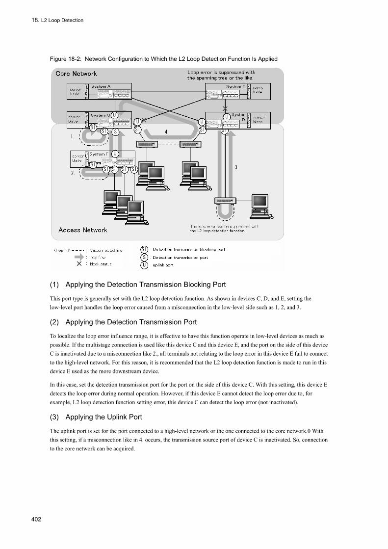
18. L2 Loop Detection
Figure 18-2: Network Configuration to Which the L2 Loop Detection Function Is Applied
(1) Applying the Detection Transmission Blocking Port
This port type is generally set with the L2 loop detection function. As shown in devices C, D, and E, setting the low-level port handles the loop error caused from a misconnection in the low-level side such as 1, 2, and 3.
(2) Applying the Detection Transmission Port
To localize the loop error influence range, it is effective to have this function operate in low-level devices as much as possible. If the multistage connection is used like this device C and this device E, and the port on the side of this device C is inactivated due to a misconnection like 2., all terminals not relating to the loop error in this device E fail to connect to the high-level network. For this reason, it is recommended that the L2 loop detection function is made to run in this device E used as the more downstream device.
In this case, set the detection transmission port for the port on the side of this device C. With this setting, this device E detects the loop error during normal operation. However, if this device E cannot detect the loop error due to, for example, L2 loop detection function setting error, this device C can detect the loop error (not inactivated).
(3) Applying the Uplink Port
The uplink port is set for the port connected to a high-level network or the one connected to the core network.0 With this setting, if a misconnection like in 4. occurs, the transmission source port of device C is inactivated. So, connection to the core network can be acquired.
402

18. L2 Loop Detection
18.1.4 Notes on Using Loop Detection
(1) Operations for Protocol VLAN and MAC VLAL
The L2 loop detection frame is the Untagged frame having the original format. It is transferred as the native VLAN for the protocol and MAC ports. So, no loop error in the protocol VLAN and MAC VLAN can be detected.
(2) Operation Performed When the Tag Conversion Function Is Used
A loop error is determined if the L2 loop detection frame sent from the Tag conversion port of this device is received with VLAN after Tag conversion. The loop error is also determined if VLAN is subjected to Tag conversion in another device and is used as a different VLAN of this device, and if it receives the L2 loop detection frame.
(3) Operating Environment of the L2 Loop Detection Function
When this function is used, the AX6700S or AX6300S device (before version 10.7) not supporting the L2 loop detection may be placed within the same network. In this case, if that device receives the loop detection frame, the frame is discarded. So, a loop error cannot be detected when it occurs in the route containing that device.
403

18. L2 Loop Detection
18.2 Configuration
18.2.1 List of Configuration CommandsThe following table lists the configuration commands used for the L2 loop detection:
Table 18-2: List of Configuration Commands
18.2.2 Setting the L2 Loop DetectionShown below is the procedure for setting the L2 loop detection function. Here, an example of setting this device C shown in the following figure is given.
Ports 0/1 and 0/2 are connected to the core network. So, uplink ports are set for them. Ports 0/3 and 0/4 are connected to low-level devices. So, detection transmission blocking ports are set for them.
Figure 18-3: Example of Setting the L2 Loop Detection
(1) Setting the L2 Loop Detection Function
[Point of setting]
Command Description
loop-detection Sets the port type for the L2 loop detection function.
loop-detection auto-restore-time Specifies the time (seconds) continuing until the inactivated port is automatically made active.
loop-detection enable Validates the L2 loop detection function.
loop-detection hold-time Specifies the time for retaining the number of L2 loop detection frames received until the port is inactivated.
loop-detection interval-time Sets the L2 loop detection frame transmission interval.
loop-detection threshold Sets the number of L2 loop detection frames received until the port is inactivated.
404

18. L2 Loop Detection
In the L2 loop detection function configuration, it is necessary to make the following two settings: enabling the function for the entire device and setting the port in which the L2 loop error is to be actually detected.
[Setup using commands]
1. (config)# loop-detection enable
The L2 loop detection function is enabled in this device.
2. (config)# interface range gigabitethernet 0/1-2
(config-if-range)# loop-detection uplink-port
(config-if-range)# exit
Ports 0/1 and 0/2 are set for uplink ports. With this setting, if ports 0/1 and 0/2 receive the L2 loop detection frame, they operate for the transmission source port according to the transmission source port type.
3. (config)# interface range gigabitethernet 0/3-4
(config-if-range)# loop-detection send-inact-port
(config-if-range)# exit
Ports 0/3 and 0/4 are set for detection transmission blocking ports. With this setting, ports 0/3 and 0/4 transmit the L2 loop detection frame. If these ports detect a loop error, they are inactivated.
(2) Setting the L2 Loop Detection Frame Transmission Interval
[Point of setting]No frame is sent exceeding the maximum transmission rate of the L2 loop detection frame. Any port or VLAN that failed to send a frame cannot detect a loop error. If the maximum transmission rate of the L2 loop detection frame is exceeded, it is necessary to make the transmission interval long to satisfy the maximum transmission rate.
[Setup using commands]
1. (config)# loop-detection interval-time 60
Set 60 seconds as the L2 loop detection frame transmission interval.
(3) Setting the Conditions for Inactivating a Port
[Point of setting]A port is generally inactivated with one loop error detection. In this case, operation is possible with the initial value (one detection) being set. However, if the loop is momentary and so the port need not be inactivated, the number of L2 loop detection frames received until the port is inactivated can be set.
[Setup using commands]
1. (config)# loop-detection threshold 100
Make the setting so that the port is inactivated by receiving 100 L2 loop detection frames.
2. (config)# loop-detection hold-time 60
Make the setting so that the number of L2 loop detection frames is retained for 60 seconds from when the last L2 loop detection frame is received.
(4) Setting the Automatic Recovery Time
[Point of setting]Set this value when making the inactivated port active automatically.
405

18. L2 Loop Detection
[Setup using commands]
1. (config)# loop-detection auto-restore-time 300
Make the setting so that the inactivated port is automatically made active again after 300 seconds.
406
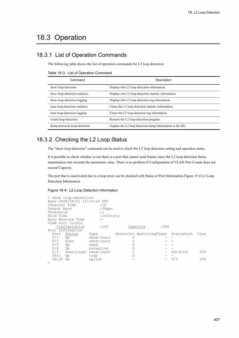
18. L2 Loop Detection
18.3 Operation
18.3.1 List of Operation CommandsThe following table shows the list of operation commands for L2 loop detection.
Table 18-3: List of Operation Command
18.3.2 Checking the L2 Loop StatusThe "show loop-detection" command can be used to check the L2 loop detection setting and operation status.
It is possible to check whether or not there is a port that cannot send frames since the L2 loop detection frame transmission rate exceeds the maximum value. There is no problem if Configuration of VLAN Port Counts does not exceed Capacity.
The port that is inactivated due to a loop error can be checked with Status of Port Information.Figure 15 4 L2 Loop Detection Information
Figure 18-4: L2 Loop Detection Information
> show loop-detectionDate 2008/04/21 12:10:10 UTCInterval Time :10Output Rate :30ppsThreshold :1Hold Time :infinityAuto Restore Time :-VLAN Port Counts Configuration :103 Capacity :300Port Information Port Status Type DetectCnt RestoringTimer SourcePort Vlan 0/1 Up send-inact 0 - - 0/2 Down send-inact 0 - - 0/3 Up send 0 - - 0/4 Up exception 0 - - 0/5 Down(loop) send-inact 1 - CH:32(U) 100 CH:1 Up trap 0 - - CH:32 Up uplink - - 0/5 100>
Command Description
show loop-detection Displays the L2 loop detection information.
show loop-detection statistics Displays the L2 loop detection statistic information.
show loop-detection logging Displays the L2 loop detection log information.
clear loop-detection statistics Clears the L2 loop detection statistic information.
clear loop-detection logging Clears the L2 loop detection log information.
restart loop-detection Restarts the L2 loop detection program.
dump protocols loop-detection Outputs the L2 loop detection dump information to the file.
407

18. L2 Loop Detection
408

Part 7 Remote Network Management
19Network Management Using SNMPThis chapter describes the support specifications of the SNMP agent function.
19.1 Overview of Network Management Using SNMP
19.2 Configuration
19.3 Operation
409

19. Network Management Using SNMP
19.1 Overview of Network Management Using SNMP
19.1.1 Outline of SNMP
(1) Network management
Advanced network management is required to maintain the operating environment or the performance of a network system. SNMP (Simple Network Management Protocol) is a network management protocol that complies with the industry standards. It can manage a multi-vender network that consists of network equipment that supports SNMP. The server that collects and manages management information is called an SNMP manager. The managed network equipment is called an SNMP agent. A network management overview is shown in the figure below.
Figure 19-1: Network Management Overview
(2) SNMP agent function
The SNMP agent of the LANSW module is a program that is integrated within the systems on the network. It has a function to provide information within the system to the SNMP manager. The information within the system is called the MIB (Management Information Base). The SNMP manager software polls the information from the system, processes it, and provides the network management information to the network manager. An example of acquiring MIB is shown in the figure below.
Figure 19-2: Example of Obtaining MIB
410

19. Network Management Using SNMP
Among the operation commands of the LANSW module, there is an SNMP command to display MIB information. This command displays the SNMP agent MIB of the local and remote systems.
The LANSW module supports SNMPv1 (RFC1157), SNMPv2C (RFC1901), and SNMPv3 (RFC3410). To perform network management by means of the SNMP manager, use SNMPv1, SNMPv2C, or SNMPv3 protocol. SNMPv1, SNMPv2C, and SNMPv3 can be used at the same time.
The SNMP agent is provided with the event report function, which is called Trap and mainly reports information on failures. Rather than periodically monitoring the system status, the SNMP manager may receive the status from the trap. Note, however, that since the Trap uses UDP, the LANSW module cannot remotely check if a trap is reached to the SNMP manager. Thus, the trap may not always arrive at the manager due to some reasons, such as network congestion. The figure below shows some sample traps.
Figure 19-3: Example of Trap
The SNMP protocol of the LANSW module supports to IPv6. MIB can be requested from the SNMP manager with the IPv4 or IPv6 address set up or traps can be transmitted to the SNMP manager, routing to the SNMP manager IP address set in the configuration. An example of a MIB request and reply from an IPv4/IPv6 SNMP manager is shown in the figure below.
Figure 19-4: Example of a MIB Request and Reply from an IPv4/IPv6 SNMP Manager
(3) SNMPv3
In SNMPv3, the management security function is enhanced to a large extent in addition to all functions of SNMPv2C. Through authentication and encryption of SNMP packets that flow on the network, SNMP packets can be protected against risks on the network such as interception, spoofing, falsification, resending, etc. that were not prevented by the security function in SNMPv2C using a combination of the community name and SNMP manager IP address.
411

19. Network Management Using SNMP
(a) SNMP entity
In SNMPv3, the SNMP manager and SNMP agent are generically called the "SNMP entities". SNMPv3 on the LANSW module supports the SNMP entity that corresponds to the SNMP agent.
(b) SNMP engine
The SNMP engine offers the services for authentication, sending/receiving encrypted messages, and controlling access to the management object. The relationship to the SNMP entity is on a 1:1 basis. The SNMP engine is identified with a unique SNMP engine ID within a management domain.
(c) User authentication and privacy function
While authentication with the community name is made in SNMPv1 and SNMPv2C, user authentication is made in SNMPv3. The privacy function (encryption and decryption) not provided in SNMPv1 and SNMPv2C is now available in SNMPv3. User authentication and privacy function can be defined for each user.
The LANSW module supports two protocols for user authentication:
• HMAC-MD5-96 (authentication protocol using the message digest algorithm. In the 128-bit digest, the first 96 bits are used. The secret key is 16 octets.)
• HMAC-SHA-96 (authentication protocol using the SHA message digest algorithm. In the 160-bit SHA digest, the first 96 bits are used. The secret key is 20 octets.)
The protocol below is supported for the privacy function.
• CBC-DES (Cipher Block Chaining - Data Encryption Standard. Encryption protocol with DES (56-bit key) as the common key algorithm enhanced in the CBC mode)
(d) Access control through MIB view
In SNMPv3, a collection of accessible MIB objects can be set for each user. This collection of MIB objects is called the MIB view. The MIB view is represented by aggregating view sub-tree indicating MIB object ID trees. For aggregation, "included" (in the MIB view) or "excluded (from the MIB view) can be selected for each view sub-tree. The MIB view can be set as the Read view, Write view, or Notify view for each user.
An example of MIB view is shown below. The MIB view summarizes and sets MIB sub-tree as a part of the MIB tree as shown in "Figure 19-5: Example of MIB View". Since object ID 1.1.2.1.2 is included in sub-tree 1.1.2.1, MIB view A can access it. However, since object ID 1.2.1 is not included in any sub-tree, it cannot be accessed. For object ID 1.1.2.1.2.1.4, sub-tree 1.1.2.1.2.1 is excluded from view A, so it cannot be accessed.
412

19. Network Management Using SNMP
Figure 19-5: Example of MIB View
19.1.2 Outline of MIBThere are two types of MIB managed by the system and provided to the SNMP manager, namely, one specified by RFC and the other information provided originally by the development vendor of the system.
The MIB specified by RFC is called standard MIB. Since it is standardized, there is no significant difference in contents among various standard MIBs. The MIB provided originally by the development vendor of the system is called private MIB, which does vary in content from one system to another. However, MIB operations (including collecting or setting up information) are common to the standard and private MIBs. An operation consists simply of specifying a system and the target MIB information. The system is specified with an ID address, and the MIB information, with an object ID.
(1) MIB structure
MIB has a tree structure. Because of this structure, each node must be represented by a number to be identified. By numbering each node in an ascending order from the root, each piece of MIB information will be uniquely identified. These numbers are called object IDs. The object ID is represented using a dot to separate the lower object group numbers. For example, object ID of sysDescr is 1.3.6.1.2.1.1.1. An example of a MIB tree structure is shown in the figure below.
413

19. Network Management Using SNMP
Figure 19-6: Example of MIB Tree Structure
(2) Representing MIB objects
Object ID consists of numbers and dots (e.g., "1.3.6.1.2.1.1.1"). Since a series of numbers is difficult to remember and use as a reference, you can specify a mnemonic called sysDescr. When using mnemonics, check the MIB mnemonic that the SNMP manager can use in advance. The mnemonics that can be used with SNMP commands of the LANSW module can be checked by executing the snmp lookup command.
(3) Index
The object ID is used to specify a MIB. However, a MIB can have one meaning or several meanings. Therefore, an index is used to specify a particular MIB. Index is a number added after the object ID to represent the order of the information.
If there is only one item in a MIB, ".0" is added to the object ID. If a single MIB has more than one item, a number is added after the object ID to show the order of the information. For example, the MIB called ifType (1.3.6.1.2.1.2.2.1.2) shows a type of interface. There are several interfaces for the LANSW module. To check the type of a particular interface, you must specify uniquely such as the "second interface type". When specifying with MIB, add the index ".2" after the MIB: e.g., ifType.2 (1.3.6.1.2.1.2.2.1.2.2).
The way to represent the index varies with each MIB. The MIB entry that is INDEX{ xxxxx,yyyyy,zzzzzz } in the MIB definition in the RFC has xxxxx, yyyyy, and zzzzzz as index. Check what kind of index is needed for each MIB before a MIB operation.
(4) Supported MIBs
The LANSW module provides MIBs necessary for management, including information on the system status, interface statistics and system devices. The definition (ASN.1) file for the private MIB is provided with the software.
See " MIB Reference" for the details of each MIB.
414

19. Network Management Using SNMP
19.1.3 SNMPv1/SNMPv2C OperationSNMP provides the following four types of operations to collect and set up the management data (MIB, Management Information Base):
• GetRequest: Acquires specified MIB information.• GetNextRequest: Acquires MIB information next to the specified one.• GetBulkRequest: An extended version of the GetNextRequest.• SetRequest: Sets a value in specified MIB.
SNMP manager performs these operations on the LANSW module (SNMP agent). Each operation is explained below.
(1) GetRequest operation
GetRequest is used to get MIB information from the LANSW module's agent function to the SNMP manager. In this operation, you can specify one or more MIBs.
When the LANSW module is maintaining the specified MIB, GetResponse returns the MIB information. If the LANSW module does not have the corresponding MIB, it returns noSuchName in the GetResponse operation. GetRequest operation is shown in the figure below.
Figure 19-7: GetRequest Operation
If the LANSW module does not have the corresponding MIB, in the case of SNMPv2C, it returns noSuchObject as a MIB value in the GetResponse operation. The GetRequest operation in the case of SNMPv2C is illustrated in the figure below.
Figure 19-8: GetRequest Operation (SNMPv2C)
415

19. Network Management Using SNMP
(2) GetNextRequest operation
The GetNextRequest operation is similar to the GetRequest operation. The GetRequest operation is used to read the specified MIB and GetNextRequest is used to get a MIB following the specified MIB. You can specify one or more MIBs also for this operation.
If the LANSW module has a MIB following the specified one, it returns the MIB in the GetResponse operation. If the specified MIB is the last one, the LANSW module returns noSuchName in the GetResponse operation. GetNestRequest operation is shown in the figure below.
Figure 19-9: GetNextRequest Operation
If the specified MIB is the last one, in the case of SNMPv2C, the LANSW module returns endOfMibView as a MIB value in the GetResponse operation. The figure below represents the GetNextRequest operation in the case of SNMPv2C.
Figure 19-10: GetNextRequest Operation (SNMPv2C)
(3) GetBulkRequest operation
The GetBulkRequest operation is an extension of the GetNextRequest operation. This operation specifies a repetition count and the number of MIBs equal to the repetition count can be obtained after the specified MIB. You can specify one or more MIBs also for this operation.
If the LANSW module has the number of MIBs corresponding to the specified repetition count from the item next to the specified MIB, it returns the MIBs in the GetResponse operation. If the specified MIB is the last one, or the last MIB is reached before the specified repetition count, endOfMibView is returned as a MIB value in the GetResponse operation. GetBulkRequest operation is shown in the figure below.
416

19. Network Management Using SNMP
Figure 19-11: GetBulkRequest Operation
(4) SetRequest operation
Like GetRequest, GetNextRequest and GetBulkRequest operations, SetRequest operation executes an operation on the LANSW module (agent function) from the SNMP manager, but it differs in the way it sets a value.
With SetRequest operation, you specify both a value to be set and a MIB. Once a value is set, the MIB and the set value are returned by GetResponse. SetRequest operation is shown in the figure below.
Figure 19-12: SetRequest Operation
(a) Response when MIB cannot be set
MIB cannot be set in the following three cases:
• Read-only MIB (including manager who is the member of a read-only community)• Incorrect set value• Due to system status
The response depends on each situation. When the MIB is read-only, GetResponse returns noSuchName. If the MIB is read-only, in the case of SNMPv2C, the LANSW module returns notWritable in the GetResponse operation. SetRequest operation when MIB is read-only is shown in the figure below.
417

19. Network Management Using SNMP
Figure 19-13: SetRequest Operation for Read-only MIB Variable
If the type of the set value is not correct, a badValue GetResponse is the response. In the case of SNMPv2C, if the type of the set value is not correct, the LANSW module returns wrongType in the GetResponse operation. The following figure shows an example of the SetRequest operation when the type of the set value is not correct.
Figure 19-14: Example of SetRequest Operation for Incorrect Type Setting
When setup fails due to the system status, genError is returned. This includes, for example, detecting a timeout in the LANSW module when you attempt to set a value. The figure below shows the SetRequest operation in the case where setting cannot be made due to a system condition.
418

19. Network Management Using SNMP
Figure 19-15: Example of SetRequest Operation Unable to Set Value Due to System Status
(5) Operations depending on community
In SNMPv1 and SNMPv2C, a concept of "community" is provided to limit the SNMP manager that executes operation. The community is the name assigned to the SNMP manager and SNMP agent as one group. When you use MIB, the SNMP manager and SNMP agent should belong to the same group (community). Community operation limitations are shown in the figure below.
Figure 19-16: Operation by Community
System A is the members of communities "public" and "localnetwork" at the same time, but not the member of "othernetwork". It does not belong to the community (othernetwork). System A accepts the MIB operations from SNMP managers A and B of the communities "public" and "localnetwork", but refuses operations from SNMP manager C of the community "othernetwork".
(6) Operation limitation by IP address
For security purposes, the LANSW module can be set up to refuse requests for operating MIB if the SNMP manager's IP address and community pairing is incorrect against the access list. When using SNMPv1 and SNMPv2C for the LANSW module, the community must be registered using the configuration command. Use character strings to set the community. Community name 'public' is commonly used.
(7) SNMP operation error status code
If an error occurs during operation, the SNMP agent sets the error code in error status, and GetResponse returns a value for the error position that tells which MIB caused the error. If the operation is successful, it sets the non-error code in error status and GetResponse returns the value of the corresponding MIB information. Error status codes are shown in
419

19. Network Management Using SNMP
the table below.
Table 19-1: Error Status Codes
19.1.4 SNMPv3 OperationSNMP provides the following four types of operations to collect and set up the management data (MIB: Management Information Base):
• GetRequest: Acquires specified MIB information.• GetNextRequest: Acquires MIB information next to the specified one.• GetBulkRequest: An extended version of the GetNextRequest.• SetRequest: Sets a value in specified MIB.
The SNMP manager performs these operations against the LANSW module (SNMP agent). Each operation is explained below.
(1) GetRequest operation
GetRequest is used to get MIB information from the LANSW module's agent function to the SNMP manager. In this operation, you can specify one or more MIBs. When the LANSW module is maintaining the specified MIB, a Response returns the MIB information.
GetRequest operation is shown in the figure below.
Error Status Code Contents
noError 0 No error.
tooBig 1 Data size is too big for PDU value.
noSuchName 2 No specified MIB, or could not write.
badValue 3 Set value is illegal.
readOnly 4 Could not write (never returned by the LANSW module).
genError 5 Any other error occurred.
noAccess 6 Setting an inaccessible MIB was attempted.
wrongType 7 A type different from that required by the MIB was specified.
wrongLength 8 Data length different from that required by the MIB was specified.
wrongEncoding 9 ASN.1 code was incorrect.
wrongValue 10 MIB value was incorrect.
noCreation 11 Corresponding MIB does not exist.
inconsistentValue 12 Value cannot be currently set for unknown reasons.
resourceUnavailable 13 Although a resource is required to set the value, the resource cannot be utilized.
commitFailed 14 Value update failed.
undoFailed 15 When value update failed, the updated value could not be reset to the original value.
notWritable 17 Cannot be set.
inconsistentName 18 The corresponding MIB does not exist, hence cannot currently be created.
420
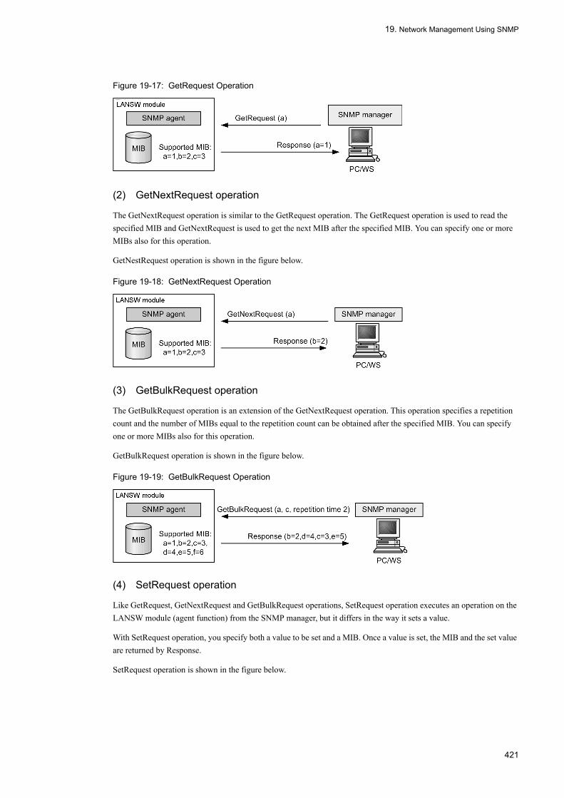
19. Network Management Using SNMP
Figure 19-17: GetRequest Operation
(2) GetNextRequest operation
The GetNextRequest operation is similar to the GetRequest operation. The GetRequest operation is used to read the specified MIB and GetNextRequest is used to get the next MIB after the specified MIB. You can specify one or more MIBs also for this operation.
GetNestRequest operation is shown in the figure below.
Figure 19-18: GetNextRequest Operation
(3) GetBulkRequest operation
The GetBulkRequest operation is an extension of the GetNextRequest operation. This operation specifies a repetition count and the number of MIBs equal to the repetition count can be obtained after the specified MIB. You can specify one or more MIBs also for this operation.
GetBulkRequest operation is shown in the figure below.
Figure 19-19: GetBulkRequest Operation
(4) SetRequest operation
Like GetRequest, GetNextRequest and GetBulkRequest operations, SetRequest operation executes an operation on the LANSW module (agent function) from the SNMP manager, but it differs in the way it sets a value.
With SetRequest operation, you specify both a value to be set and a MIB. Once a value is set, the MIB and the set value are returned by Response.
SetRequest operation is shown in the figure below.
421

19. Network Management Using SNMP
Figure 19-20: SetRequest Operation
(a) Response when MIB cannot be set
MIB cannot be set in the following three cases:
• MIB is read-only• Incorrect set value• Due to system status
The response depends on each situation. When the MIB is read-only, notWritable is returned by Response. SetRequest operation when MIB is read-only is shown in the figure below.
Figure 19-21: SetRequest Operation for Read-only MIB Variable
If the type of the set value is not correct, wrongType is returned by Response. The following figure shows an example of the SetRequest operation when the type of the set value is not correct.
Figure 19-22: Example of SetRequest Operation for Incorrect Type Setting
When setup fails due to the LANSW module status, genError is returned. This includes, for example, detecting a timeout in the LANSW module when you attempt to set a value. The figure below shows the SetRequest operation in the case where setting cannot be made due to a system condition.
Figure 19-23: Example of SetRequest Operation Unable to Set Value Due to System Status
422

19. Network Management Using SNMP
(5) Restriction to operation in SNMPv3
While restriction is made using a combination of community and SNMP manager address in SNMPv1 and SNMPv2C, the MIB operation is restricted using user authentication and the MIB view in SNMPv3. When using SNMPv3 for the LANSW module, the SNMP security user, MIB view, and security group must be registered using the configuration command. For trap sending, the SNMP security user, MIB view, security group, and trap sending SNMP manager must be registered using the configuration command.
(6) SNMPv3 operation error status code
If an error occurs during operation, the SNMP agent returns a Response containing an error code in error status and an error position value that tells which MIB caused the error. If the operation result is normal, the SNMP agent returns a Response containing a non-error code in error status and the value of corresponding MIB information. Error status codes are shown in the table below.
Table 19-2: Error Status Codes
19.1.5 Trap
(1) Trap overview
The SNMP agent has an event notification (including information on the failure and logging) called Trap (Trap) . A trap asynchronously notifies the SNMP manager of important events from the SNMP agent. The SNMP manager can detect the system status change through receipt of a trap. Based on this notification, it can get detailed information by obtaining MIB information from the system.
Since traps use UDP, arrival of a trap from the system to the SNMP manager cannot be verified. For this reason, there are cases where a trap does not reach the manager because of congestion of the network or other reasons. The figure
Error Status Code Contents
noError 0 No error.
tooBig 1 Data size is too big for PDU value.
noSuchName 2 No specified MIB, or could not write.
badValue 3 Set value is illegal.
readOnly 4 Could not write (never returned by the LANSW module).
genError 5 Any other error occurred.
noAccess 6 Setting an inaccessible MIB was attempted.
wrongType 7 A type different from that required by the MIB was specified.
wrongLength 8 Data length different from that required by the MIB was specified.
wrongEncoding 9 ASN.1 code was incorrect.
wrongValue 10 MIB value was incorrect.
noCreation 11 Corresponding MIB does not exist.
inconsistentValue 12 Value cannot be currently set for unknown reasons.
resourceUnavailable 13 Although a resource is required to set the value, the resource cannot be utilized.
commitFailed 14 Value update failed.
undoFailed 15 When value update failed, the updated value could not be reset to the original value.
authorizationError 16 Authentication failed.
notWritable 17 Cannot be set.
inconsistentName 18 The corresponding MIB does not exist, hence cannot currently be created.
423
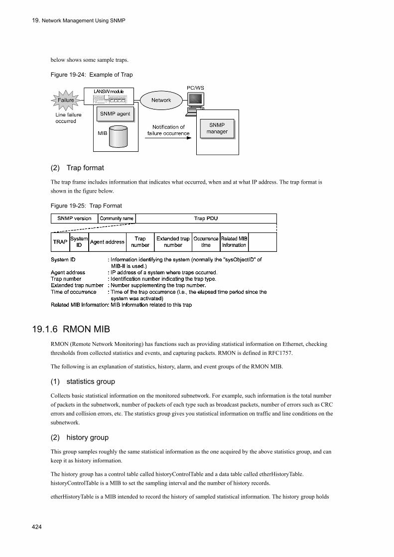
19. Network Management Using SNMP
below shows some sample traps.
Figure 19-24: Example of Trap
(2) Trap format
The trap frame includes information that indicates what occurred, when and at what IP address. The trap format is shown in the figure below.
Figure 19-25: Trap Format
19.1.6 RMON MIBRMON (Remote Network Monitoring) has functions such as providing statistical information on Ethernet, checking thresholds from collected statistics and events, and capturing packets. RMON is defined in RFC1757.
The following is an explanation of statistics, history, alarm, and event groups of the RMON MIB.
(1) statistics group
Collects basic statistical information on the monitored subnetwork. For example, such information is the total number of packets in the subnetwork, number of packets of each type such as broadcast packets, number of errors such as CRC errors and collision errors, etc. The statistics group gives you statistical information on traffic and line conditions on the subnetwork.
(2) history group
This group samples roughly the same statistical information as the one acquired by the above statistics group, and can keep it as history information.
The history group has a control table called historyControlTable and a data table called etherHistoryTable. historyControlTable is a MIB to set the sampling interval and the number of history records.
etherHistoryTable is a MIB intended to record the history of sampled statistical information. The history group holds
424

19. Network Management Using SNMP
the statistical information for a certain period of time within the system. Therefore, this feature imposes lesser burden on the network, as compared to SNMP managers that acquire statistical information by means of periodical polling, and allows continuous acquisition of statistical information for a given period of time.
(3) alarm group
The alarm group MIB is used to set the check interval and threshold of the monitored object MIB and log or issue trap to the SNMP manager when that MIB reaches the threshold.
For example, the alarm group collects log information when it detects failure to capture packets more than 10 times in the five minutes configured as the sample time, and sends the trap to the SNMP manager. You must configure the event group to use this alarm group.
(4) event group
The eventTable group specifies action when the MIB threshold configured in the alarm group is exceeded, and the logTable group records the log information when the threshold is exceeded.
The eventTable group MIB is used to specify whether to record the log, send the trap to the SNMP manager, do both, or do nothing when the threshold is reached.
The logTable group records the log within the system when the eventTable group is configured to record the log. The number of log entries in the system is limited and when the maximum number of entries is reached, older log information is deleted as newer information is added. You should periodically backup records to the SNMP manager, before they are removed from the system.
425

19. Network Management Using SNMP
19.2 Configuration
19.2.1 List of Configuration CommandsThe following table lists the configuration commands related to SNMP/RMON:
Table 19-3: List of Configuration Commands
19.2.2 Setting MIB Access Authorization in SNMPv1/SNMPv2C[Point of setting]
Set up the privilege for the SNMP manager to access the MIB on the LANSW module.
[Setup using commands]
1. (config)# access-list 1 permit 128.1.1.2 0.0.0.0
Sets the access list to authorize the access from IP address 128.1.1.2.
2. (config)# snmp-server community "NETWORK" ro 1
Sets the MIB access modes and applied access list against SNMP manager communities.• Community name: NETWORK• Access list: 1• Access mode: read only
19.2.3 Setting MIB Access Authorization in SNMPv3[Point of setting]
To access MIBs by SNMPv3, set a group of MIB objects for a MIB view to authorize access, and set information on user authentication and privacy function for an SNMP security user. To associate the MIB view and SNMP
Command Description
hostname Specifies the host name for the LANSW module. This corresponds to sysName of RFC1213.
rmon alarm Sets the control setting information of RMON (RFC1757) alarm group.
rmon collection history Sets the control information of statistical history of RMON (RFC1757) Ethernet.
rmon event Sets the control setting information of RMON (RFC1757) event group.
snmp-server community Sets the access list against SNMP communities.
snmp-server contact Sets the contact information for the LANSW module. This corresponds to sysContact of RFC1213.
snmp-server engineID local Sets SNMP engine ID information.
snmp-server group Sets SNMP security group information.
snmp-server host Registers the network manager (SNMP Manager) to send traps.
snmp-server location Sets the name of the location that the LANSW module is installed. This corresponds to sysLocation of RFC1213.
snmp-server traps Sets the triggers for traps.
snmp-server user Sets SNMP security user information.
snmp-server view Sets MIB view information.
snmp trap link-status Inhibits to send traps ("SNMP link down" and "up" traps) when the line (link) is up or down.
426

19. Network Management Using SNMP
security user each other, set an SNMP security group.
[Setup using commands]
1. (config)# snmp-server view "READ_VIEW" 1.3.6.1 included
(config)# snmp-server view "READ_VIEW" 1.3.6.1.6.3 excluded
(config)# snmp-server view "WRITE_VIEW" 1.3.6.1.2.1.1 included
Sets MIB view.• Registers the internet group MIB (sub-tree: 1.3.6.1) for view name READ_VIEW.• Excludes the snmpModules group MIB (sub-tree: 1.3.6.1.6.3) from view name READ_VIEW.• Registers the system group MIB (sub-tree: 1.3.6.1.2.1.1) for view name WRITE_VIEW.
2. (config)# snmp-server user "ADMIN" "ADMIN_GROUP" v3 auth md5 "ABC*_1234" priv
des "XYZ/+6789"
Sets the SNMP security user.• SNMP security user name: ADMIN• SNMP security group name: ADMIN_GROUP• Authentication protocol: HMAC-MD5• Authentication password: ABC*_1234• Encryption protocol: CBC-DES• Encryption password: XYZ/+6789
3. (config)# snmp-server group "ADMIN_GROUP" v3 priv read "READ_VIEW" write
"WRITE_VIEW"
Sets the SNMP security group.• SNMP security group name: ADMIN_GROUP• Security level: Authentication provided, encryption provided• Read view name: READ_VIEW• Write view name: WRITE_VIEW
19.2.4 Setting to Send Trap in SNMPv1/SNMPv2C[Point of setting]
Register the SNMP Manager to issue traps.
[Setup using commands]
1. (config)# snmp-server host 128.1.1.2 traps "NETWORK" version 1 snmp
Sets the SNMP manager to issue the standard traps.• Community name: NETWORK• SNMP manager IP address: 128.1.1.2• Traps to issue: standard trap
19.2.5 Setting to Send Trap in SNMPv3[Point of setting]
Set the MIB view and SNMP security user. Then, set the SNMP security group and SNMP trap mode.
427

19. Network Management Using SNMP
[Setup using commands]
1. (config)# snmp-server view "ALL_TRAP_VIEW" * included
Sets MIB view.• Registers all sub-trees for view name ALL_TRAP_VIEW.
2. (config)# snmp-server user "ADMIN" "ADMIN_GROUP" v3 auth md5 "ABC*_1234" priv
des "XYZ/+6789"
Sets the SNMP security user.• SNMP security user name: ADMIN• SNMP security group name: ADMIN_GROUP• Authentication protocol: HMAC-MD5• Authentication password: ABC*_1234• Encryption protocol: DES• Encryption password: XYZ/+6789
3. (config)# snmp-server group "ADMIN_GROUP" v3 priv notify "ALL_TRAP_VIEW"
Sets the SNMP security group.• SNMP security group name: ADMIN_GROUP• Security level: Authentication provided, encryption provided• Notify view name: ALL_TRAP_VIEW
4. (config)# snmp-server host 128.1.1.2 traps "ADMIN" version 3 priv snmp
Sets the SNMP manager to issue the standard traps in SNMPv3.• SNMP manager's IP address: 128.1.1.2• SNMP security user name: ADMIN• Security level: Authentication provided, encryption provided• Traps issued: standard trap
19.2.6 Suppressing Link TrapThe LANSW module issues an SNMP trap when a link is enabled or disabled at the Ethernet interface, by default. Sending of link traps can be suppressed by Ethernet interface through configuration. For example, you can reduce unnecessary processes burdening the LANSW module, network or SNMP manager by allowing output of traps only for the important lines such as the ones connecting the LANSW module to servers, while suppressing others to send link traps.
[Point of setting]The link trap setup must be designed according to the entire network operation policy.
428

19. Network Management Using SNMP
Figure 19-26: Block Diagram for Link Traps
Port 0/1 sends traps and does not need to be configured. Port 0/12 must be set up not to send traps.
[Setup using commands]
1. (config)# interface gigabitethernet 0/12
(config-if)# no snmp trap link-status
Specifies not to send traps when link enabled/disabled.
2. (config-if)# exit
19.2.7 Setting RMON Ethernet History-group Control Information[Point of setting]
Set up the information to control the statistical history of RMON (RFC1757) Ethernet. This command allows to configure up to 32 entries. Before this setup, the SNMP manager must be defined.
[Setup using commands]
1. (config)# interface gigabitethernet 0/5
Moves to Gigabit Ethernet interface 0/5 mode.
2. (config-if)# rmon collection history controlEntry 33 owner "NET-MANAGER"
buckets 10
Sets the information to control the statistical history, including the Information ID, Configurator ID and the number of history entries to store the statistics.• Information ID: 33• Acquired entry of statistical history: 10 entries• ID: "NET-MANAGER"
19.2.8 Checking Threshold of Specific MIB Value Using RMON[Point of setting]
Set to regularly check the specific MIB value against the thresholds, and if exceeded, notify the SNMP manager of the event.Before using traps to report on events, set up the SNMP trap mode.
429

19. Network Management Using SNMP
[Setup using commands]
1. (config)# rmon event 3 log trap public
Sets the event to perform when an alarm arises.• Information ID: 3• Event executing methods: log, trap• Trap community name: public
2. (config)# rmon alarm 12 "ifOutDiscards.3" 256111 delta rising-threshold 400000
rising-event-index 3 falling-threshold 100 falling-event-index 3 owner
"NET-MANAGER"
Sets the information to control the RMON alarm group according to the following conditions:• Identification number of RMON alarm group control information: 12• Object flag of MIB where threshold is checked: ifOutDiscards.3• Interval: 256111 seconds• Threshold check method: Difference value check (delta)• Maximum threshold: 400000• Identification number of event method when maximum threshold is exceeded: 3• Minimum threshold: 100• Identification number of event method when minimum threshold is exceeded: 3• ID of Configurator: NET-MANAGER
430

19. Network Management Using SNMP
19.3 Operation
19.3.1 List of Operation CommandsThe following table lists the operation commands related to SNMP/RMON:
Table 19-4: List of Operation Commands
19.3.2 Checking Communication with SNMP ManagerIf the SNMP agent function is set on the LANSW module for network management by the SNMP protocol, check the following:
The SNMP manager on the network must be able to acquire MIB from the LANSW module.
The SNMP trap must be transmitted from the LANSW module to the SNMP manager on the network.
The check procedure is described below. For MIB that can be fetched from the LANSW module and the traps sent from The LANSW module, see manuals, "MIB Reference, 1 Summary of Supported MIBs"and "MIB Reference, 4.2 Supported Trap-PDU Parameters[CB 320] 4.3 Supported Trap-PDU Parameters[CB 2000]", respectively.
1. Execute the "ping" command by specifying the IP address of the SNMP manager and make sure that IP communication from the LANSW module to the SNMP manager is possible. If communication is unavailable, see "Troubleshooting Guide".
2. Make sure that the SNMP manager can acquire MIB from the LANSW module. If MIB cannot be acquired, see "Troubleshooting Guide".
Command Description
snmp lookup Displays the support MIB object name and object ID.
snmp get Displays the value of the specified MIB.
snmp getnext Displays the value of the next specified MIB.
snmp walk Displays the specified MIB tree.
snmp getif Displays the MIB information of interface group.
snmp getroute Displays ipRouteTabler (IP routing table).
snmp getarp Displays ipNetToMediaTable (IP address conversion table).
snmp getforward Displays ipForwardTable (IP forwarding table).
snmp rget Displays the value of MIB of the specified remote system.
snmp rgetnext Displays the value of the next MIB of the specified remote system.
snmp rwalk Displays the MIB tree of the specified remote system.
snmp rgetroute Displays ipRouteTabler (IP routing table) of the specified remote system.
snmp rgetarp Displays the ipNetToMediaTable (IP address conversion table) of the specified remote system.
431

19. Network Management Using SNMP
432

20Log OutputThis chapter describes log output of the LANSW module.
20.1 Log Output Overview
20.2 Configuration
433

20. Log Output
20.1 Log Output Overview
The LANSW module reports the operational or error information as operation messages. These messages are sent to operation terminals and stored within the LANSW module as an operation log. This information can be used to manage the LANSW module operating status or fault occurrence.
The operation log stores events during the LANSW module operation in the order of occurrences and the same contents as the operational messages. Log information contained in operation log includes:
• Operator message and reply message• Operation message
The functional log contains operation information on errors and warnings categorized by message ID with the dates and times the event occurred first and last, and the number of accumulations.
The LANSW module stores these logs in the text format. The system administrator can view this information using the display commands.
The collected log information can be forwarded using the syslog interface to other systems (such as UNIX workstation)
on the network *1, *2. E-mails are also available to send the log information to other devices on the network. Where considerable systems that must be managed reside, the logs can be managed centrally using these log output functions. The log information can be sent by e-mails.
*1Receiving syslog messages from other system are not supported.
*2The HOSTNAME field of the HEADER defined by RFC3164 is unspecified for syslog messages generated by the LANSW module.
434

20. Log Output
20.2 Configuration
20.2.1 List of Configuration CommandsThe following table lists the configuration commands for the log output:
Table 20-1: List of Configuration Commands (Setup for syslog Output)
Table 20-2: List of Configuration Commands (Setup for E-Mail Output)
20.2.2 Setting "syslog" Output[Point of setting]
Set up the LANSW module to send the collected log information to syslog server using the syslog output.
[Setup using commands]
1. (config)# logging host LOG_HOST
Sets the output the log to host LOG_HOST.
20.2.3 Setting Log Output by E-mail[Point of setting]
Set up the LANSW module to send the collected log information to remote hosts or PCs by e-mails.
[Setup using commands]
1. (config)# logging email system@loghost
Sets "system@loghost" as the destination mail address.
Command Description
logging event-kind Sets the event types for the log information to be sent, in the syslog server.
logging facility Sets the facilities used to output the log information via syslog interface.
logging host Sets the output destination for the log information.
logging trap Sets the level of importance of the log information to be sent, in the syslog server.
Command Description
logging email Sets e-mail addresses to output the log information by e-mails.
logging email-event-kind Sets the event types for the log information to output by e-mails.
logging email-from Sets the sources to output the log information by e-mail.
logging email-interval Sets the time interval for the output of the log information by e-mail.
logging email-server Sets the SMTP server information to output the log information by e-mail.
435

20. Log Output
436
21sFlow Statistics (Flow Statistics) FunctionThis chapter describes the sFlow statistics function that analyzes the traffic characteristics of packets relayed on the LANSW module, and how to use it.
21.1 sFlow Statistics Overview
21.2 Configuration
21.3 Operation
437

21. sFlow Statistics (Flow Statistics) Function
21.1 sFlow Statistics Overview
21.1.1 Outline of sFlow StatisticssFlow statistics is the function that monitors traffic over the network using the relay system (e.g. router or switch) to analyze end-to-end traffic (flow) characteristics and the traffic characteristics of the neighboring network. sFlow statistics function supports statistical information from layer 2 to layer 7 in the internationally disclosed flow statistics protocol (RFC 3176). The system that receives and displays the sFlow statistical information (hereinafter referred to as sFlow packets) is called the sFlow collector. The LANSW module that sends sFlow packets to the sFlow collector is called the sFlow agent. An example of network configuration using sFlow statistics is shown in the figure below.
Figure 21-1: Example of Network Configuration Using sFlow Statistics
Figure 21-2: System Configuration
Information monitored by the sFlow statistics agent on the LANSW module is collected by the collector. The analyzer can graphically display the statistics result. Therefore, to use the sFlow statistics function, the collector and analyzer are essential.
438

21. sFlow Statistics (Flow Statistics) Function
Table 21-1: System Components
* In some cases, it may be integrated with the analyzer.
21.1.2 sFlow Statistics Agent FunctionThe sFlow agent on the LANSW module has two functions:
• Function to create flow statistics (for sFlow statistics, flow sample. Hereinafter, referred to as flow sample)• Function to create interface statistics (for sFlow statistics, counter sample. Hereinafter, referred to as counter sample)
The flow sample creating function samples received frames (packets) at the user-specified rate, processes frame information, and reports the flow sample to the sFlow collector. The counter sample creating function reports interface statistics in the counter sample format to the sFlow collector. The figure below shows the respective collection location and contents.
Figure 21-3: Flow Sample and Counter Sample
21.1.3 sFlow Packet FormatThe sFlow packets (flow sample packet and counter sample packet) reported by the LANSW module to the sFlow collector are described below. The format for reporting to the collector is specified in RFC 3176. The figure below shows the format of the sFlow packet.
Figure 21-4: sFlow Packet Format
(1) sFlow header
The contents of setting in the sFlow header are listed in the table below.
Component Role
Agent Collects statistics information and sends it to the collector.
Collector * Counts, edits, and displays the statistics information sent by the agent. Further, sends the edited data to the analyzer.
Analyzer Graphically displays the data sent by the collector.
439

21. sFlow Statistics (Flow Statistics) Function
Table 21-2: sFlow Header Format
(Legend) Y: Supported
(2) Flow sample
Flow sample is the format for extracting packets at the certain sampling interval among the packets that are identified as the packets to be forwarded to another system or the incoming packets, and reporting them to the sFlow collector. In addition to the monitored packets, flow sample collects information (input interface, output interface, AS number, etc.) not contained in the packets, so detailed network monitoring is allowed. The figure below shows the format of the flow sample.
Figure 21-5: Flow Sample Format
(a) Flow sample header
The contents of setting in the flow sample header are listed in the table below.
Table 21-3: Flow Sample Header Format
Setting Item Description Support
Version number sFlow packet version (versions 2 and 4 supported) Y
Address type sFlow agent IP type (IPv4=1, IPv6=2) Y
AgentIP address
sFlow agent IP address Y
Sequence number Number incremented for each creation of sFlow packet Y
Time of creation Current time (ms from the system start) Y
Number of samples Number of packets sampled (flow and counter) contained in this signal(For the example in "Figure 21-4: sFlow Packet Format", "n + m" is set.)
Y
Setting Item Description Support
sequence_number Number incremented for each creation of flow sample Y
source_id SNMP Interface Index indicating the source of flow sample in the LANSW module (input interface)
Y
sampling_rate Sampling interval for flow sample Y
sample_pool Total number of packets that arrived at the interface Y
drops Total number of discarded flow samples Y
input SNMP Interface Index of input interfaceIf interface is unknown, 0 is set.
Y
output SNMP Interface Index of output interface *1
If interface is unknown, 0 is set.N
440

21. sFlow Statistics (Flow Statistics) Function
(Legend) Y: Supported N: Not supported* Fixed to 0 since the LANSW module does not support output.
(b) Basic data format
There are three types of basic data formats; the HEADER type, IPv4 type, and IPv6 type, one of which only can be set. By default, the basic data format is the HEADER type. Set the IPv4 type or IPv6 type using the configuration command if you want to use it. The table below gives the format of each type.
Table 21-4: HEADER Type Format
(Legend) Y: SupportedNote: This format is used when it cannot be analyzed as IP packet.
Table 21-5: IPv4 Type Format
(Legend) Y: Supported
Table 21-6: IPv6 Type Format
Setting Item Description Support
packet_information_type Type of basic data format (HEADER type = 1) Y
header_protocol Header protocol number (ETHERNET=1) Y
frame_length Original packet length Y
header_length Packet length sampled from original (default: 128) Y
header<> Contents of sampled packet Y
Setting Item Description Support
packet_information_type Type of basic data format (IPv4 type = 2) Y
length IPv4 packet length Y
protocol IP protocol type (e.g. TCP=6, UDP=17) Y
src_ip Source IP address Y
dst_ip Destination IP address Y
src_port Source port number Y
dst_port Destination port number Y
tcp_flags TCP flag Y
TOS IP type of service Y
Setting Item Description Support
packet_information_type Type of basic data format (IPv6 type = 3) Y
length IPv6 packet length excluding lower layer Y
protocol IP protocol type (e.g. TCP=6, UDP=17) Y
src_ip Source IP address Y
dst_ip Destination IP address Y
src_port Source port number Y
dst_port Destination port number Y
tcp_flags TCP flag Y
priority Priority Y
441

21. sFlow Statistics (Flow Statistics) Function
(Legend) Y: Supported
(c) Extended data format
There are five types of extended data formats; the switch type, router type, gateway type, user type, and URL type. By default, all extended formats are collected and reported to the collector. This format can be changed in configuration. The table below gives the format of each type.
Table 21-7: List of Extended Data Format Types
(Legend) Y: Supported*1 Not collected as sFlow packets when relayed via L2.*2 Not collected as sFlow packets if frames with two or more VLAN Tags are the target.
Table 21-8: Switch Type Format
(Legend) Y: Supported N: Not supported* Fixed to 0 because this is not supported.
Table 21-9: Router Type Format
(Legend) Y: Supported* Collected as 0 when the route to the destination address is a multipath route.
Table 21-10: Gateway Type Format
Extended data type Description Support
Switch Collects switch information (VLAN information, etc.). Y
Router Collects router information (NextHop, etc.). Y*1*2
Gateway Collects gateway information (AS number, etc.). Y*1*2
User Collects user information (TACACS/RADIUS information, etc.). Y*2
URL Collects URL information (URL information, etc.). Y*2
Setting Item Description Support
extended_information_type Type of extended data format (SWITCH type = 1) Y
src_vlan 802.1Q VLAN ID of input frame Y
src_priority 802.1p priority of input frame Y
dst_vlan 802.1Q VLAN ID of output frame* N
dst_priority 802.1p priority of output frame* N
Setting Item Description Support
extended_information_type Type of extended data format (ROUTER type = 2) Y
nexthop_address_type IP address type of next forwarding destination router Y*
nexthop IP address of next forwarding destination router Y*
src_mask Prefix mask bit of source address Y
dst_mask Prefix mask bit of destination address Y
Setting Item Description Support
extended_information_type Type of extended data format (GATEWAY type = 3) Y
as AS number of the LANSW module Y
442

21. sFlow Statistics (Flow Statistics) Function
(Legend) Y: Supported N: Not supported*1 AS number is collected as 0 when the destination/source is a direct route.*2 The neighboring AS number when the destination is searched from the LANSW module. It may be different from the actual neighboring AS number.*3 Fixed to 0 because this is not supported.
Table 21-11: User Type Format
(Legend) Y: Supported N: Not supported* Fixed to 0 because this is not supported.
Table 21-12: URL Type Format
(Legend) Y: Supported
(3) Counter sample
Counter sample reports interface statistical information (number of arrived packets, error count, etc.). The interface type determines the format for reporting to the collector. The figure below shows the format of counter sample.
src_as AS number of source Y*1
src_peer_as Neighbor AS number to source Y*1*2
dst_as_path_len Number of AS information (fixed to 1) Y
dst_as_type AS route type (2: AS_SEQUENCE) Y
dst_as_len Number of ASs (fixed to 2) Y
dst_peer_as Neighbor AS number to destination Y*1
dst_as AS number of destination Y*1
communities<> Community relating to this route *3 N
localpref Local priority relating to this route *3 N
Setting Item Description Support
extended_information_type Type of extended data format (USER type = 4) Y
src_user_len Source user name length Y
src_user<> Source user name Y
dst_user_len Destination user name length * N
dst_user<> Destination user name * N
Setting Item Description Support
extended_information_type Type of extended data format (URL type = 5) Y
url_direction URL information source(source address=1, destination address=2)
Y
url_len URL length Y
url<> URL contents Y
Setting Item Description Support
443

21. sFlow Statistics (Flow Statistics) Function
Figure 21-6: Counter Sample Format
(a) Counter sample header
The contents of setting in the counter sample header are listed in the table below.
Table 21-13: Counter Sample Header Format
(Legend) Y: Supported
(b) Counter sample type
The counter sample types are categorized for each interface type and collected. The contents of setting as the counter sample type are listed in the table below.
Table 21-14: List of Counter Sample Types
(Legend) Y: Supported N: Not supported*1 The interface type is not supported on the LANSW module.*2 the LANSW module does not support VLAN statistics.
(c) Counter sample information
The counter sample information to be collected depends on the counter sample type. Information other than VLAN statistics is reported according to the statistical information (RFC) used by MIB. The contents of setting as the counter sample information are listed in the table below.
Setting Item Description Support
sequence_number Number incremented for each creation of counter sample Y
source_id SNMP Interface Index indicating the source of counter sample in the LANSW module (particular port)
Y
sampling_interval Interval of reporting counter sample to collector Y
Setting Item Description Support
GENERIC General statistics (counters_type=1) N*1
ETHERNET Ethernet statistics (counters_type=2) Y
TOKENRING Token ring statistics (counters_type=3) N*1
FDDI FDDI statistics (counters_type=4) N*1
100BaseVG VG statistics (counters_type=5) N*1
WAN WAN statistics (counters_type=6) N*1
VLAN VLAN statistics (counters_type=7) N*2
444

21. sFlow Statistics (Flow Statistics) Function
Table 21-15: Counter Sample Information
(Legend) Y: Supported N: Not supported* Among Ethernet statistics, ifDirection, dot3StatsSymbolErrors, and ifOutUcastPkts cannot be collected.
21.1.4 sFlow Statistics Operation on the LANSW module
(1) Notes on collection target packets for sFlow statistics• sFlow statistics on the LANSW module deals with received packets and sent packets as target packets.• The packet that is identified to be discarded when sent (packets identified to be discarded by the filtering function,
etc.) is handled as a packet not subject to sFlow statistics.• Software relayed packets and packets originating/terminating at the LANSW module are handled as packets not
subject to sFlow statistics.• Packets transmitted from a mirror port of port mirroring are handled as packets not subject to sFlow statistics.
(2) Notes on data collection location• Regardless of the ingress/egress setting, the contents of the sFlow packet as entered into the LANSW module are
collected (even if the packet contents are changed within the LANSW module, the change is not applied to sFlow packet).
• sFlow statistics on the LANSW module samples received packets or sent packets, and reports them to the sFlow collector. Because of this feature, forwarding may be reported to the collector even though packets are to be discarded by setting the filtering function or QoS function on the output side. If the filtering function or QoS function is being used together with this function, check the conditions for discarding packets before starting the operation. Conditions for collecting sFlow statistics when another function is also being used are shown in the table below.
Table 21-16: sFlow Statistics Collection Conditions When Another Function Is Also Being Used
* The contents of sFlow packets as entered into the LANSW module are collected.
Setting Item Description Support
GENERIC General statistics [See RFC 2233.] N
ETHERNET Ethernet statistics [See RFC 2358.] Y*
TOKENRING Token ring statistics [See RFC 1748.] N
FDDI FDDI statistics [See RFC 1512.] N
100BaseVG VG statistics [See RFC 2020.] N
WAN WAN statistics [See RFC 2233.] N
VLAN VLAN statistics [See RFC 3176.] N
Function Received Packet Subject to sFlow Statistics Sent packet Subject to sFlow Statistics
Filtering function Collected even if it is to be discarded Not collected when it is to be discarded*
QoS function (terminating side)
Collected even if it is to be discarded Not collected when it is to be discarded*
QoS function (originating side)
Collected even if it is to be discarded Collected even if it is to be discarded*
Terminating at the local system
Not collected Not collected
Originating from the local system
Not collected Not collected
445

21. sFlow Statistics (Flow Statistics) Function
21.2 Configuration
21.2.1 List of Configuration CommandsThe following table lists the configuration commands used for sFlow statistics:
Table 21-17: List of Configuration Commands
21.2.2 Basic Configuration of sFlow Statistics
(1) Setting for monitoring received packets
[Point of setting]For sFlow statistics configuration, two types of settings, valid setting on the entire system and setting for specifying the port to be actually operated, are required. Setting for monitoring packets incoming to port 0/4 is shown below.
Command Description
sflow destination Specifies the IP address of the collector system as the sFlow packet destination.
sflow extended-information-type Specifies whether each extended data format of flow sample must be reported.
sflow forward egress Sets sending traffic on the specified port as the sFlow statistics monitoring target.
sflow forward ingress Sets receiving traffic on the specified port as the sFlow statistics monitoring target.
sflow max-header-size Specifies the maximum size from the beginning of sample packet to be copied if HEADER type is used for basic data format (see the "sflow packet-information-type" command).
sflow max-packet-size Specifies the sFlow packet size.
sflow packet-information-type Specifies the basic data format of flow sample.
sflow polling-interval Specifies the interval for reporting counter sample to the collector system.
sflow sample Specifies the sampling interval to be applied to the entire system.
sflow source Specifies the IP address set as the sFlow packet source (agent).
sflow url-port-add Additionally specifies a port number other than 80 to identify HTTP packets when URL information is being used as an extended data format.
sflow version Sets the version of sFlow packets to be sent.
446

21. sFlow Statistics (Flow Statistics) Function
Figure 21-7: Example of Setting for Monitoring Packets Received on Port 0/4
[Setup using commands]
1. (config)# sflow destination 192.1.1.12
Sets IP address 192.1.1.12 for the sFlow collector.
2. (config)# sflow sample 512
Monitors traffic for each 512 packets.
3. (config)# interface gigabitethernet 0/4
Changes to port 0/4 Ethernet interface configuration mode.
4. (config-if)# sflow forward ingress
Enables the sFlow statistics function for packets received on port 0/4.
(2) Setting for monitoring sent packets
[Point of setting]Enabling the sFlow statistics function for received packets or sent packets is determined by which is specified, the
447

21. sFlow Statistics (Flow Statistics) Function
"sflow forward ingress" command or "sflow forward egress" command, upon setting in the interface configuration mode. Setting for monitoring packets outgoing from port 0/2 is shown below.
Figure 21-8: Example of Setting for Monitoring Packets Sent on Port 0/2
[Setup using commands]
1. (config)# sflow destination 192.1.1.12
Sets IP address 192.1.1.12 for the sFlow collector.
2. (config)# sflow sample 512
Monitors traffic for each 512 packets.
3. (config)# interface gigabitethernet 0/2
Changes to port 0/2 Ethernet interface configuration mode.
4. (config-if)# sflow forward egress
Enables the sFlow statistics function for packets sent on port 0/2.
[Note]• This setting is not available for AX3630S-48TW and AX3630S-48T2XW.
448

21. sFlow Statistics (Flow Statistics) Function
21.2.3 Example of Setting sFlow Statistics Configuration Parameter
(1) Adjusting MTU length and sFlow packet size
[Point of setting]By default, the sFlow packet is reported to the sFlow collector with a size of 1400 byte or smaller. If the line MTU value to the sFlow collector is larger, reporting to the sFlow collector can be efficiently achieved by setting the sFlow packet size to the same value. Setting in the case of the collector connected to a line with an MTU length of 8000 byte is described below.
Figure 21-9: Example for Setting Reporting to sFlow Collector to MTU = 8000 byte
[Setup using commands]
1. (config)# sflow destination 192.1.1.12
Sets IP address 192.1.1.12 for the sFlow collector.
2. (config)# sflow sample 32
Monitors traffic for each 32 packets.
3. (config)# sflow max-packet-size 8000
Sets the maximum value of sFlow packet size to 8000 byte.
4. (config)# interface gigabitethernet 0/4
Changes to port 0/4 Ethernet interface configuration mode.
5. (config-if)# sflow forward ingress
Enables the sFlow statistics function for packets received on port 0/4.
449

21. sFlow Statistics (Flow Statistics) Function
(2) Limiting the information to be collected
[Point of setting]All of sFlow packet information is collected unless the configuration is specified. However, if there is unnecessary information, the CPU usage can be reduced with the setting for not collecting such information. Setting requiring IP address information only is described below.
[Setup using commands]
1. (config)# sflow destination 192.1.1.12
Sets IP address 192.1.1.12 for the sFlow collector.
2. (config)# sflow sample 512
Monitors traffic for each 512 packets.
3. (config)# sflow packet-information-type ip
Sets the IP type for basic data format of flow sample.
4. (config)# sflow extended-information-type router
Sets "ROUTER" for extended data format of flow sample (router information only can be acquired).
5. (config)# interface gigabitethernet 0/4
Changes to port 0/4 Ethernet interface configuration mode.
6. (config-if)# sflow forward ingress
Enables the sFlow statistics function for packets received on port 0/4.
(3) Fixing the agent IP address of sFlow packet
[Point of setting]General sFlow collectors identify the system based on the agent IP address value contained in the sFlow packet. Because of that, if the agent IP address is not specified by the "sflow source" or "interface loopback", sFlow collector may display as if the packet is sent from more than one system. To examine the information in a long term, fix the agent IP address. The example below sets packets to be set to the sFlow collector using the IP address assigned to "loopback" as the agent IP address.
[Setup using commands]
1. (config)# interface loopback 0
Changes to loopback interface configuration mode.
2. (config-if)# ip address 176.1.1.11
Sets 176.1.1.11 for IPv4 on loopback interface.
3. (config-if)# ipv6 address 3ffe:100::1
(config-if)# exit
Sets 3ffe:100::1 for IPv6 on loopback interface.
4. (config)# sflow destination 192.1.1.12
Sets IP address 192.1.1.12 for the sFlow collector.
5. (config)# sflow sample 512
450

21. sFlow Statistics (Flow Statistics) Function
Monitors traffic for each 512 packets.
6. (config)# interface gigabitethernet 0/4
Changes to port 0/4 Ethernet interface configuration mode.
7. (config-if)# sflow forward ingress
Enables the sFlow statistics function for packets received on port 0/4.
[Note]If a loopback IP address is being used, setting by the "sflow source" command is not required. If an IP address has been specified using the "sflow source" command, the IP address takes precedence.
(4) Collecting URL information in local network environment
[Point of setting]By default, 80 is used as the destination port number when collecting URL information (HTTP packets) for sFlow statistics on the LANSW module. However, in a local network, the port number may be different. Setting for using 8080 as the HTTP packet port number in a local network environment is shown below.
[Setup using commands]
1. (config)# sflow destination 192.1.1.12
Sets IP address 192.1.1.12 for the sFlow collector.
2. (config)# sflow sample 512
Monitors traffic for each 512 packets.
3. (config)# sflow url-port-add 8080
Additionally sets a destination port number of 8080 to identify HTTP packets when URL information is being used as an extended data format.
4. (config)# interface gigabitethernet 0/4
Changes to port 0/4 Ethernet interface configuration mode.
5. (config-if)# sflow forward ingress
Enables the sFlow statistics function for packets received on port 0/4.
[Note]Destination port number 80 as the HTTP packet target is valid even after this parameter is set.
451

21. sFlow Statistics (Flow Statistics) Function
21.3 Operation
21.3.1 List of Operation CommandsThe following table lists the operation commands used for sFlow statistics:
Table 21-18: List of Operation Commands
21.3.2 Checking Communication with sFlow CollectorIf the sFlow statistics function is being set on the LANSW module for reporting to the sFlow collector, check the following:
(1) Checking communication with sFlow collector
Execute the "ping" command with the IP address of the sFlow collector specified and make sure that IP communication from the LANSW module to the sFlow collector is possible. If communication is unavailable, see manual "Troubleshooting Guide".
(2) Checking sFlow packet communication
Make sure that the sFlow collector receives sFlow packets.
If the packets are not received, see manual "Troubleshooting Guide".
21.3.3 Checking Operation of sFlow Statistics FunctionThe operation contents that can be checked using the sFlow statistics on the LANSW module are as follows:
(1) Checking number of sFlow packets discarded
Execute the "show sflow" command to display the sFlow statistical information, and check the Dropped sFlow samples (number of packets being discarded) and Overflow Time of sFlow Queue (time to discard packets). If either of the values increases, set the appropriate sampling interval to prevent the increase of the value.
Command Description
show sflow Displays the setting condition and operation status of the sFlow statistics function.
show sflow detail Displays the setting condition, operation status, and detail information of the sFlow statistics function.
clear sflow statistics Clears statistics information managed by sFlow statistics.
restart sflow Restarts the flow statistics program.
dump sflow Outputs debug information collected in the flow statistics program to a file.
452

21. sFlow Statistics (Flow Statistics) Function
Figure 21-10: Execution Result of "show sflow" Command
> show sflowDate 2006/12/13 14:10:32 UTCsFlow service status: enableProgress time from sFlow statistics cleared: 16:00:05sFlow agent data : sFlow service version : 4 CounterSample interval rate: 60 seconds Default configured rate: 1 per 2048 packets Default actual rate : 1 per 2048 packets Configured sFlow ingress ports : 0/2-4 Configured sFlow egress ports : ---- Received sFlow samples : 37269 Dropped sFlow samples : 2093 Exported sFlow samples : 37269 Couldn't export sFlow samples : 0 Overflow time of sFlow queue: 12 seconds ...1sFlow collector data : Collector IP address: 192.168.4.199 UDP:6343 Source IP address: 130.130.130.1 Send FlowSample UDP packets : 12077 Send failed packets: 0 Send CounterSample UDP packets: 621 Send failed packets: 0 Collector IP address: 192.168.4.203 UDP:65535 Source IP address: 130.130.130.1 Send FlowSample UDP packets : 12077 Send failed packets: 0 Send CounterSample UDP packets: 621 Send failed packets: 0
1. If the time to discard packets increases, review the setting of sampling interval.
(2) Checking CPU usage
Execute the "show cpu" command to display the CPU usage and check the load. If CPU usage is high, re-set sampling interval using configuration command "sflow".
Figure 21-11: Execution Result of show cpu Command
>show cpu minutesDate 2006/12/13 14:15:37 UTC*** minute ***date time cpu averageDec 13 14:42:00-14:42:59 6Dec 13 14:43:00-14:43:59 20 : :Dec 13 15:41:00-15:41:59 10 ...1
1. If CPU usage is high, review the setting of sampling interval.
21.3.4 Adjusting Sampling Interval for sFlow StatisticsThe sampling interval adjusting method when using the sFlow statistics on the LANSW module is as follows:
(1) Adjusting with line speed
Use the "show interfaces" command to check pps on all ports that enable the sFlow statistic function. If received packets are the target, total "Input rate". If sent packets are the target, total "Output rate" as well. The value of the total divided by 100 is the sampling interval for reference. Set the sampling interval with this value. Check to see if the number of discarded packets increases using the "show sflow" command.
An example of reference sampling interval for received packets on port 0/4 and port 0/5 is shown below.
453
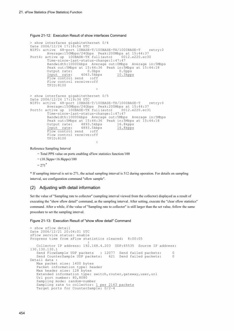
21. sFlow Statistics (Flow Statistics) Function
Figure 21-12: Execution Result of show interfaces Command
> show interfaces gigabitethernet 0/4Date 2006/12/24 17:18:54 UTCNIF0: active 48-port 10BASE-T/100BASE-TX/1000BASE-T retry:0 Average:150Mbps/24Gbps Peak:200Mbps at 15:44:37Port4: active up 100BASE-TX full(auto) 0012.e220.ec30 Time-since-last-status-change:1:47:47 Bandwidth:10000kbps Average out:0Mbps Average in:5Mbps Peak out:5Mbps at 15:44:36 Peak in:5Mbps at 15:44:18 Output rate: 0.0bps 0.0pps Input rate: 4063.5kbps 10.3kpps Flow control send :off Flow control receive:off TPID:8100 : > show interfaces gigabitethernet 0/5Date 2006/12/24 17:19:34 UTCNIF0: active 48-port 10BASE-T/100BASE-TX/1000BASE-T retry:0 Average:150Mbps/24Gbps Peak:200Mbps at 15:44:37Port5: active up 100BASE-TX full(auto) 0012.e220.ec31 Time-since-last-status-change:1:47:47 Bandwidth:10000kbps Average out:5Mbps Average in:5Mbps Peak out:5Mbps at 15:44:36 Peak in:5Mbps at 15:44:18 Output rate: 4893.5kbps 16.8kpps Input rate: 4893.5kbps 16.8kpps Flow control send :off Flow control receive:off TPID:8100 :
Reference Sampling Interval= Total PPS value on ports enabling sFlow statistics function/100= (10.3kpps+16.8kpps)/100
= 271*
* If sampling interval is set to 271, the actual sampling interval is 512 during operation. For details on sampling interval, see configuration command "sflow sample".
(2) Adjusting with detail information
Set the value of "Sampling rate to collector" (sampling interval viewed from the collector) displayed as a result of executing the "show sflow detail" command, as the sampling interval. After setting, execute the "clear sflow statistics" command. After a while, if the value of "Sampling rate to collector" is still larger than the set value, follow the same procedure to set the sampling interval.
Figure 21-13: Execution Result of "show sflow detail" Command
> show sflow detailDate 2006/12/21 20:04:01 UTCsFlow service status: enableProgress time from sFlow statistics cleared: 8:00:05 : Collector IP address: 192.168.4.203 UDP:65535 Source IP address: 130.130.130.1 Send FlowSample UDP packets : 12077 Send failed packets: 0 Send CounterSample UDP packets: 621 Send failed packets: 0Detail data : Max packet size: 1400 bytes Packet information type: header Max header size: 128 bytes Extended information type: switch,router,gateway,user,url Url port number: 80,8080 Sampling mode: random-number Sampling rate to collector: 1 per 2163 packets Target ports for CounterSample: 0/2-4
454

Part 8 Managing Information on Neighboring Systems
22LLDPThis chapter provides an outline and operation procedures of LLDP, a function to collect information on the neighboring system.
22.1 LLDP Overview
22.2 Configuration
22.3 Operation
455
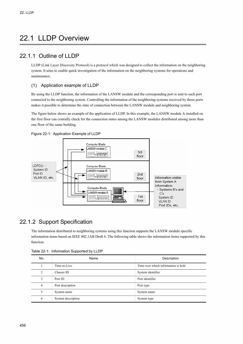
22. LLDP
22.1 LLDP Overview
22.1.1 Outline of LLDPLLDP (Link Layer Discovery Protocol) is a protocol which was designed to collect the information on the neighboring system. It aims to enable quick investigation of the information on the neighboring systems for operations and maintenance.
(1) Application example of LLDP
By using the LLDP function, the information of the LANSW module and the corresponding port is sent to each port connected to the neighboring system. Controlling the information of the neighboring systems received by those ports makes it possible to determine the state of connection between the LANSW module and neighboring system.
The figure below shows an example of the application of LLDP. In this example, the LANSW module A installed on the first floor can centrally check for the connection states among the LANSW modules distributed among more than one floor of the same building.
Figure 22-1: Application Example of LLDP
22.1.2 Support SpecificationThe information distributed to neighboring systems using this function supports the LANSW module specific information items based on IEEE 802.1AB Draft 6. The following table shows the information items supported by this function.
Table 22-1: Information Supported by LLDP
No. Name Description
1 Time-to-Live Time over which information is held
2 Chassis ID System identifier
3 Port ID Port identifier
4 Port description Port type
5 System name System name
6 System description System type
456
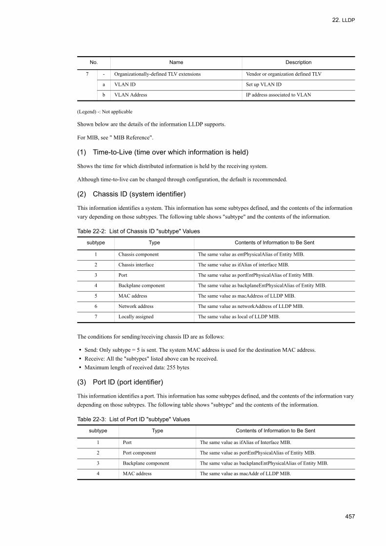
22. LLDP
(Legend) -: Not applicable
Shown below are the details of the information LLDP supports.
For MIB, see " MIB Reference".
(1) Time-to-Live (time over which information is held)
Shows the time for which distributed information is held by the receiving system.
Although time-to-live can be changed through configuration, the default is recommended.
(2) Chassis ID (system identifier)
This information identifies a system. This information has some subtypes defined, and the contents of the information vary depending on those subtypes. The following table shows "subtype" and the contents of the information.
Table 22-2: List of Chassis ID "subtype" Values
The conditions for sending/receiving chassis ID are as follows:
• Send: Only subtype = 5 is sent. The system MAC address is used for the destination MAC address.• Receive: All the "subtypes" listed above can be received.• Maximum length of received data: 255 bytes
(3) Port ID (port identifier)
This information identifies a port. This information has some subtypes defined, and the contents of the information vary depending on those subtypes. The following table shows "subtype" and the contents of the information.
Table 22-3: List of Port ID "subtype" Values
7 - Organizationally-defined TLV extensions Vendor or organization defined TLV
a VLAN ID Set up VLAN ID
b VLAN Address IP address associated to VLAN
subtype Type Contents of Information to Be Sent
1 Chassis component The same value as entPhysicalAlias of Entity MIB.
2 Chassis interface The same value as ifAlias of interface MIB.
3 Port The same value as portEntPhysicalAlias of Entity MIB.
4 Backplane component The same value as backplaneEntPhysicalAlias of Entity MIB.
5 MAC address The same value as macAddress of LLDP MIB.
6 Network address The same value as networkAddress of LLDP MIB.
7 Locally assigned The same value as local of LLDP MIB.
subtype Type Contents of Information to Be Sent
1 Port The same value as ifAlias of Interface MIB.
2 Port component The same value as portEntPhysicalAlias of Entity MIB.
3 Backplane component The same value as backplaneEntPhysicalAlias of Entity MIB.
4 MAC address The same value as macAddr of LLDP MIB.
No. Name Description
457
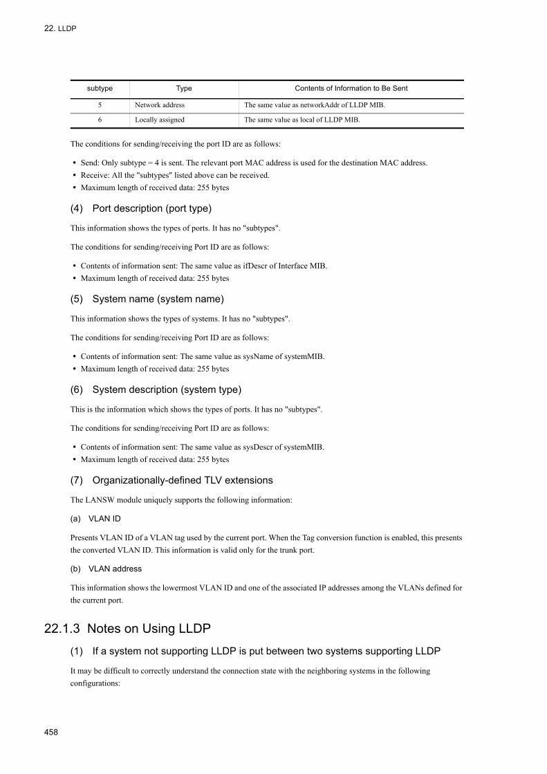
22. LLDP
The conditions for sending/receiving the port ID are as follows:
• Send: Only subtype = 4 is sent. The relevant port MAC address is used for the destination MAC address.• Receive: All the "subtypes" listed above can be received.• Maximum length of received data: 255 bytes
(4) Port description (port type)
This information shows the types of ports. It has no "subtypes".
The conditions for sending/receiving Port ID are as follows:
• Contents of information sent: The same value as ifDescr of Interface MIB.• Maximum length of received data: 255 bytes
(5) System name (system name)
This information shows the types of systems. It has no "subtypes".
The conditions for sending/receiving Port ID are as follows:
• Contents of information sent: The same value as sysName of systemMIB.• Maximum length of received data: 255 bytes
(6) System description (system type)
This is the information which shows the types of ports. It has no "subtypes".
The conditions for sending/receiving Port ID are as follows:
• Contents of information sent: The same value as sysDescr of systemMIB.• Maximum length of received data: 255 bytes
(7) Organizationally-defined TLV extensions
The LANSW module uniquely supports the following information:
(a) VLAN ID
Presents VLAN ID of a VLAN tag used by the current port. When the Tag conversion function is enabled, this presents the converted VLAN ID. This information is valid only for the trunk port.
(b) VLAN address
This information shows the lowermost VLAN ID and one of the associated IP addresses among the VLANs defined for the current port.
22.1.3 Notes on Using LLDP
(1) If a system not supporting LLDP is put between two systems supporting LLDP
It may be difficult to correctly understand the connection state with the neighboring systems in the following configurations:
5 Network address The same value as networkAddr of LLDP MIB.
6 Locally assigned The same value as local of LLDP MIB.
subtype Type Contents of Information to Be Sent
458

22. LLDP
• If two systems supporting LLDP are connected each other via a switch not supporting LLDP, the LLDP information is forwarded via the switch. The LANSW modules supporting OADP recognize the information from the source not directly connected as the neighboring information, so now it is impossible to distinguish the information of directly connected switch and that of indirectly connected switch.
• If two systems supporting LLDP are connected each other via a router, the distributed information of LLDP is discarded by the router. Therefore, the information is not received.
(2) Compatibility with other vendors' systems
The LANSW module cannot interconnect with other vendor's proprietary Link Layer Discovery Protocol*.
*Cisco Systems: CDP (Cisco Discovery Protocol)Extreme Networks: EDP (Extreme Discovery Protocol)Foundry Networks: FDP (Foundry Discovery Protocol)
(3) Compatibility with IEEE 802.1AB standards
The LLDP of the LANSW module is a proprietary function based on IEEE 802.1AB Draft 6. Thus, it does not support connectivity with the IEEE 802.1AB standards.
(4) About the maximum number of neighboring systems
One system can accommodate the information of up to 50 neighboring systems. If this number is exceeded, the received information is discarded. The discarding state continues for a certain time length to assure the time period for the deletion of the received information on neighboring systems by timeout. This time length is equal to the retention time for the neighboring system information exceeded the threshold.
459

22. LLDP
22.2 Configuration
22.2.1 List of Configuration CommandsThe following table lists the LLDP configuration commands:
Table 22-4: List of Configuration Commands
22.2.2 Setting LLDP
(1) LLDP functional setup
[Point of setting]The LLDP function requires two configurations: one to enable this function system wide, and the other to run LLDP on a specific port.The following describes how to operate the LLDP functions on gigabitethernet 0/1.
[Setup using commands]
1. (config)# lldp run
Enables the LLDP all over the LANSW module.
2. (config)# interface gigabitethernet 0/1
Changes to port 0/1 Ethernet interface configuration mode.
3. (config-if)# lldp enable
Starts to operate LLDP on port 0/1.
(2) Setup for transmission intervals and retaining period of LLDP frames
[Point of setting]You can adjust the timing to reflect changes in received information by adjusting the interval to transmit LLDP frames. The shorter the transmitting interval the faster the change is updated, and the longer the transmission interval, the slower the change is updated.
[Setup using commands]
1. (config)# lldp interval-time 60
Sets the transmission interval for LLDP frames to 60 seconds.
2. (config)# lldp hold-count 3
Sets up the time period the neighboring systems retain the information received from the LANSW module to the time length calculated by multiplying "interval-time" by the number of times. In this example, 60 sec. × 3 = 180 sec.
Command Description
lldp enable Starts to operate LLDP on the specified port.
lldp hold-count Sets the time period the neighbor system holds the LLDP frame from the LANSW module.
lldp interval-time Sets the time intervals the LANSW module transmits LLDP frames.
lldp run Enables the LLDP all over the LANSW module.
460

22. LLDP
22.3 Operation
22.3.1 List of Operation CommandsThe following table lists the LLDP operation commands:
Table 22-5: List of Operation Commands
22.3.2 Displaying LLDP InformationUse "show lldp" to display the LLDP information. "show lldp" shows the information on the LLDP setup and the number of the neighboring systems per port. "show lldp detail" shows the detailed information on the neighboring system.
Figure 22-2: Execution Result of "show lldp" Command
> show lldpDate 2005/11/09 19:16:20 UTCStatus: Enabled Chassis ID: Type=MAC Info=0012.e268.2c21Interval Time: 30 Hold Count: 4 TTL:120Port Counts=30/1 (CH:10) Link:Up Neighbor Counts: 20/2 Link:Down Neighbor Counts: 00/3 Link:Up Neighbor Counts: 0>
Figure 22-3: Execution Result of "show lldp detail" Command
> show lldp detailDate 2005/11/09 19:16:34 UTCStatus: Enabled Chassis ID: Type= MAC Info=0012.e268.2c21Interval Time: 30 Hold Count: 4 TTL:120System Name: LLDP1System Description: ALAXALA AX3630S AX-3630S-24T2X [AX3630S-24T2X] Switching software Ver. 10.0 [OS-L3L]Total Neighbor Counts=2Port Counts=3Port 0/1 (CH:10) Link: Up Neighbor Counts: 2 Port ID: Type=MAC Info=0012.e298.5cc0 Port Description: GigabitEther 0/1 Tag ID: Tagged=1,10-20,4094 IPv4 Address: Tagged: 10 192.168.248.240 IPv6 Address: Tagged: 20 3ffe:501:811:ff01:200:8798:5cc0:e7f4 1 TTL:110 Chassis ID: Type=MAC Info=0012.e268.2505 System Name: LLDP2 System Description: ALAXALA AX2430S AX-2430S-48T [AX2430S-48T] Switching
Command Description
show lldp Shows the information of the LLDP settings and the neighboring system.
show lldp statistics Shows the LLDP statistics.
clear lldp Clears the LLDP information on the neighboring systems.
clear lldp statistics Clears the LLDP statistics information.
restart lldp Restarts the LLDP program.
dump protocols lldp Outputs into a file the detailed event-trace and control-table information collected by the LLDP program.
461

22. LLDP
software Ver. 10.0 [OS-L2] Port ID: Type=MAC Info=0012.e298.dc20 Port Description: GigabitEther 0/5 Tag ID: Tagged=1,10-20,4094 IPv4 Address: Tagged: 10 192.168.248.220 2 TTL:100 Chassis ID: Type=MAC Info=0012.e268.2c2d System Name: LLDP3 System Description: ALAXALA AX3630S AX-3630S-24T2X [AX3630S-24T2X] Switching software Ver. 10.0 [OS-L3L] Port ID: Type=MAC Info=0012.e298.7478 Port Description: GigabitEther 0/24 Tag ID: Tagged=1,10-20,4094 IPv4 Address: Tagged: 10 192.168.248.200 IPv6 Address: Tagged: 20 3ffe:501:811:ff01:200:8798:7478:e7f4Port 0/2 Link: Down Neighbor Counts: 0Port 0/3 Link: Up Neighbor Counts: 0>
462
23OADPThis chapter provides an outline and operation procedures of OADP, a function to collect information on the neighboring devices.
23.1 OADP Overview
23.2 Configuration
23.3 Operation
463

23. OADP
23.1 OADP Overview
23.1.1 Outline of OADP
(1) OADP function overview
The OADP (Octpower Auto Discovery Protocol) run in layer 2 to collect information on the neighboring systems by exchanging OADP PDU (Protocol Data Unit), and displays the connectivity with the neighboring systems.
This function displays the system information and port information of the neighboring system, allowing an easy understanding of connection status between systems without login to the neighboring system or referencing the network configuration diagram. The function also allows to check for whether the systems are connected correctly by comparing the connection state against the network configuration diagram.
Systems that can be identified as neighboring system include systems using CDP or OADP.
(2) Outline of CDP receiving function
Since the OADP can interpret CDP (Cisco Discovery Protocol), it can check for the configurations of the connections with the LANSW modules supporting CDP PDU. However, the LANSW module itself does not output CDP PDU. CDP is a neighboring system detection protocol that runs on layer 2 level of Cisco products.
(3) Example of application of OADP
The OADP function sends the information on the system and ports connected to the neighboring system. Information on the LANSW module and port includes device IDs, port IDs, IP addresses or VLAN IDs. The connection state between the LANSW module and neighboring systems can be determined by receiving information from the neighboring systems through the corresponding port.
The figure below shows an example of the application of OADP. In this example, the LANSW module A installed on the first floor can determine the connection state among the LANSW modules installed in each floor of the same building.
464

23. OADP
Figure 23-1: Example of Application of OADP
23.1.2 Support Specification
(1) OADP support specification
The items and specification supported by OADP are shown in the table below.
Table 23-1: Item/Specification Supported by OADP
(Legend) Y: Supported N: Not supported
(2) Information used by OADP
The following table shows the information supported OADP PDU:
Table 23-2: Information Supported by OADP
Item Contents
Applicable layer Layer 2 Y
Layer 3 N
OADP PDU exchange unit Physical port or link aggregation
Reset function Y
OADP PDU transmission interval 5 - 254 seconds in increments of 1 second
OADP PDU information hold time 10 - 255 seconds in increments of 1 second
CDP receiving function Y
No. Name Description
1 Device ID Identifier uniquely identifying the system
2 Address Address of the port sending OADP PDU
3 Port ID ID of the port sending OADP PDU
465

23. OADP
The following table shows the information that may be found in the received CDP PDU. Number 1 to 7 are the same as OADP PDU.
Table 23-3: Information Supported by CDP
23.1.3 Notes on Using OADP
(1) Connecting a system not supporting OADP between two systems supporting OADP
It may be difficult to correctly understand the connection state with the neighboring systems in the following configurations:
• If two systems supporting OADP are connected each other via a switch not supporting OADP, the OADP information is forwarded via the switch. Thus since the LANSW modules can receive the distributed information as the neighboring information from the source not connected directly, it is difficult to distinguish the information from that from a partner system directly connected.
• If two systems supporting OADP are connected each other via a router, the distributed information of OADP is discarded by the router. Therefore, the information is not received.
(2) About the maximum number of neighboring systems
One system can accommodate the information of up to 100 neighboring systems. If this limit is exceeded, the received information is discarded. The discarding setup survives for a certain time to reserve the time for deleting received information on the neighboring systems due to timeout. This time is equal to the duration the information on the neighboring systems beyond the system limit is held.
(3) VLAN on port using OADP
OADP exchanges OADP PDU on the VLAN set up on a port. If this VLAN is disabled (using "state suspend"), OADP does not operate on the VLAN.
4 Capabilities Function of the system
5 Version Software version
6 Platform Platform
7 Duplex Duplex information on the port sending OADP PDU
8 ifIndex ifIndex of the port sending OADP PDU
9 ifSpeed ifSpeed of the port sending OADP PDU
10 VLAN ID VLAN ID of the port sending OADP PDU
11 ifHighSpeed ifHighSpeed of the port sending OADP PDU
No. Name Description
1 Device ID Identifier uniquely identifying the system
2 Address Address of the port sending CDP PDU
3 Port ID ID of the port sending CDP PDU
4 Capabilities Function of the system
5 Version Software version
6 Platform Platform
7 Duplex Duplex information of the port sending CDP PDU
No. Name Description
466

23. OADP
(4) Connecting to system supporting CDP
When a system with CDP implemented is connected via the trunk port, do not disable the native VLAN of that trunk port (by the "state suspend" command). When disabled, CDP PDU is discarded on the LANSW module.
(5) Replacing L2 switch placed between systems supporting CDP
Suppose you replace an L2 switch (transparent to CDP) with the system placed between systems supporting CDP. In this case if you set up the LANSW module to receive CDP (by "oadp cdp-listener" command), the neighboring systems supporting CDP cannot recognize each other anymore, since the LANSW module receives CDP PDUs instead of transmitting them transparently. If you do not apply such a setting, the LANSW module does not receive CDP but transmits it transparently, so the LANSW modules supporting CDP can recognize each other as before the replacement.
467

23. OADP
23.2 Configuration
23.2.1 List of Configuration CommandsThe following table lists the OADP configuration commands:
Table 23-4: List of Configuration Commands
23.2.2 Setting OADP
(1) Setup for OADP function
[Point of setting]The OADP function requires two configurations: one to enable this function system wide, and the other to run OADP on a specific port.If the port to be set up with OADP is a member of a link aggregation, this setup must be applied to the port channel interface.Tha following describes how to operate the OADP function on gigabitethernet 0/1.
[Setup using commands]
1. (config)# oadp run
Enables OADP system wide.
2. (config)# interface gigabitethernet 0/1
Changes to port 0/1 Ethernet interface configuration mode.
3. (config-if)# oadp enable
Starts to operate OADP on port 0/1.
[Note]OADP operates on a VLAN active on a the port. OADP does not operate on a VLAN set up as "suspend".
(2) Setup for transmission intervals and retaining period of OADP frames
[Point of setting]You can adjust the timing to reflect changes in received information by adjusting the interval to transmit OADP frames. The shorter the transmitting intervals the faster the change is updated, however, this and neighboring systems may be loaded excessively. The longer the transmission interval, the lower the load, however, it delays reflection of update. Usually you do not need to change this setting.
Command Description
oadp cdp-listener Enables the CDP receiving functions.
oadp enable Enables the OADP on a port or link aggregation.
oadp hold-time Sets the time period over which the neighboring system holds the OADP frames sent from the LANSW module.
oadp ignore-vlan Sets to ignore OADP frames from a specified VLAN ID.
oadp interval-time Sets the time interval the LANSW module sends OADP frames.
oadp run Enables OADP system wide.
468

23. OADP
[Setup using commands]
1. (config)# oadp interval-time 60
Sets the transmission intervals for OADP frames to 60 seconds.
2. (config)# oadp hold-time 180
Sets the time period the neighboring systems retain the information received from the LANSW module to 180 seconds.
(3) Setup for CDP receiving function
[Point of setting]When the CDP receiving function is enabled, the CDP receiving function is activated on all the ports with OADP set up.The following describes how to operate the CDP receiving function on gigabitethernet 0/1.
[Setup using commands]
1. (config)# interface gigabitethernet 0/1
Changes to port 0/1 Ethernet interface configuration mode.
2. (config-if)# oadp enable
Enables the OADP on port 0/1.
3. (config-if)# exit
Returns from the Ethernet interface configuration mode to the global configuration mode.
4. (config)# oadp cdp-listener
Enables the CDP receiving functions. The CDP receiving function is activated on all the ports with OADP set up.
(4) Setup for VLAN ignoring OADP frames
[Point of setting]OADP uses VLAN tags to exchange more than one OADP frames per port over the trunk port. As the number of VLANs in the trunk port increases, the amount of information on the neighboring systems too increases, resulting in heavy processing load on the LANSW module. To reduce the loading on the LANSW module, set up VLAN so that it ignores the OADP frames received.
[Setup using commands]
1. (config)# oadp ignore-vlan 10-20
Sets to ignore the OADP frames received over VLANs 10 to 20.
469

23. OADP
23.3 Operation
23.3.1 List of Operation CommandsThe following table lists the OADP operation commands:
Table 23-5: List of Operation Commands
23.3.2 Displaying OADP InformationUse "show oadp" to display the OADP information. "show oadp" shows the information on the OADP setup and simple information on each port. "show oadp detail" shows the detailed information on the neighboring system.
Figure 23-2: Execution Result of "show oadp"
> show oadpDate 2005/11/09 19:50:20 UTCOADP/CDP status: Enabled/Disabled Device ID: OADP-1Interval Time: 60 Hold Time: 180ignore vlan: 2-4,10Enabled Port: 0/1-5,16,20 CH 10 Total Neighbor Counts=2Local VID Holdtime Remote VID Device ID Capability Platform0/1 0 35 0/8 0 OADP-2 RS AX3630S-24T2X0/16 0 9 0/1 0 OADP-3 S AX2430S-48T Capability Codes: R - Router, T - Trans Bridge, B - Source Route Bridge S - Switch, H - Host, I - IGMP, r - Repeater>
Command Description
show oadp Shows the information on the OADP/CDP configurations and the neighboring system.
show oadp statistics Displays the OADP/CDP statistics.
clear oadp Clears the OADP/CDP neighboring information.
clear oadp statistics Clears the OADP/CDP statistics.
restart oadp Restarts the OADP program.
dump protocols oadp Dumps the detailed event-trace and control-table information collected by the OADP program into files.
470

23. OADP
Figure 23-3: Execution Result of "show oadp detail" Command
> show oadp detailDate 2005/11/09 19:55:52 UTCOADP/CDP status: Enabled/Disabled Device ID: OADP-1Interval Time: 60 Hold Time: 180ignore vlan: 2-4,10Enabled Port: 0/1-5,16,20 Total Neighbor Counts=2---------------------------------------------------------Port: 0/1 VLAN ID: 0Holdtime : 6(sec)Port ID : 0/8 VLAN ID(TLV): 0Device ID : OADP-2Capabilities : Router, SwitchPlatform : AX3630S-24T2XEntry address(es): IP address : 192.16.170.87 IPv6 address: fe80::200:4cff:fe71:5d1cIfSpeed : 1G Duplex : FULLVersion : ALAXALA AX3630S AX-3630S-24T2X [AX3630S-24T2X] Switching software Ver. 10.0 [OS-L3L]---------------------------------------------------------Port: 0/16 VLAN ID: 0Holdtime : 10(sec)Port ID : 0/1 VLAN ID(TLV): 0Device ID : OADP-3Capabilities : SwitchPlatform : AX2430S-48TEntry address(es): IP address : 192.16.170.100IfSpeed : 1G Duplex : FULLVersion : ALAXALA AX2430S AX-2430S-48T [AX2430S-48T] Switching software Ver. 10.0 [OS-L2]--------------------------------------------------------->
471

23. OADP
472

Part 9 Port Mirroring
24Port MirroringPort mirroring is a function to transmit a copy of a received or transmitted frame to a specified physical port. This chapter describes the port mirroring and how to use it.
24.1 Port Mirroring Overview
24.2 Configuration
473

24. Port Mirroring
24.1 Port Mirroring Overview
24.1.1 Outline of Port MirroringPort mirroring is a function to transmit a copy of a received or transmitted frame to a specified physical port. The act of copying a frame is called mirroring. When monitoring or analyzing traffics, this function is helpful to receive mirrored frames by an analyzer.
The following figures schematically illustrates the mirroring for the received and transmitted frames respectively:
Figure 24-1: Mirroring Received Frames
Figure 24-2: Mirroring Transmitted Frames
As illustrated in the above figures, the physical port that monitors the traffic is called the monitor port, and the physical port to which mirrored frames are transmitted is called the mirror port.
The mirror port transmits only the mirrored frames. All the other originating, terminating, or relayed frames are discarded. Mirrored frames are transmitted without TTL (IPv4) or hop limit (IPv6) decremented.
The monitoring port and mirror port can be set up in a "many to one" configuration, thus enabling frame copies received from multiple monitoring ports to be transmitted to one single mirror port. Note that frames copied using a monitor port cannot be sent to more than one mirror port.
No operation command is provided for the port mirroring. Make sure that frames are correctly mirrored by checking for them using an analyzer connected to the mirror port.
24.1.2 Notes on Using Port Mirroring
(1) Coexistence with another function• In the monitor port, other functions operate without the limitation.• The VLAN function and three layer communication function cannot be used in the mirror port. Functions such as
SNMP and DHCP that require the function and three layer communication functions such as the spanning tree, Ring
Protocol, and IGMP snooping/MLD snooping that require the VLAN function cannot be used.
474

24. Port Mirroring
(2) Notes on Using Port Mirroring• Frames copied by port mirroring cannot be output beyond the line bandwidth of the mirror port.• If the FCS of a received frame is faulty, that frame is not mirrored.• When mirroring transmitted frames, only frames forwarded by hardware are mirrored. Frames transmitted by
software (including originating frames or those with IP options set) are not mirrored. When mirroring received frames, all the received frames including originating frames or those with IP options set are mirrored.
• Mirroring transmitted frames allows to set up only one session.• For the mirroring of a outgoing frames, tagged frames having the VLAN tag for outgoing frames are mirrored even
when untagged frames are sent. • For the mirroring of a outgoing frames, tagged frames having the VLAN tag for outgoing frames rather than the
VLAN tag used on the LAN are mirrored even when the sending port has the tag translation function set.
475

24. Port Mirroring
24.2 Configuration
24.2.1 List of Configuration CommandsThe port mirroring configuration command list is shown in the table below.
Table 24-1: List of Configuration Commands
24.2.2 Setting Port MirroringFor the port mirroring configuration, the monitor and mirror ports pair must be set up as the monitor session. The LANSW module allows to set up to four pairs of monitor sessions.
Each pair uses session numbers, 1 to 4. To delete a monitor session, specify the predefined session number. When specifying the existing session number the contents of the associated monitor session are updated, causing the existing monitor session information overwritten.
To the monitor port, assign the port to use for communications. To the mirror port, assign the port to connect an analyzer for monitoring or analyzing traffic. The mirror port do not accept any communications other than for the port mirroring.
Mirroring for the transmitted and exchanged frames can be set up only for the monitor session with session number 1.
(1) Mirroring received frames
[Point of setting]Only Ethernet interface can be used for this setting. When using for the link aggregation, also specify a single Ethernet interface. The mirror port must be set up on any port not set up with VLAN.
[Setup using commands]
1. (config)# monitor session 2 source interface gigabitethernet 0/1 rx destination
interface gigabitethernet 0/5
Connects an analyzer to port 0/5 to set up that the frames received on 1Gbit Ethernet interface 1/0 are mirrored. Uses session number 2.
(2) Mirroring transmitted frames
[Point of setting]Only Ethernet interface can be used for this setting. When using for the link aggregation, also specify a single Ethernet interface. The mirror port must be set up on any port not set up with VLAN. The session number must be 1.
[Setup using commands]
1. (config)# monitor session 1 source interface gigabitethernet 0/2 tx destination
interface gigabitethernet 0/6
Connects an analyzer to port 0/6 to set up that the frames transmitted on 1Gbit Ethernet interface 1/2 are mirrored. Uses session number 1.
Command Description
monitor session Sets port mirroring.
476
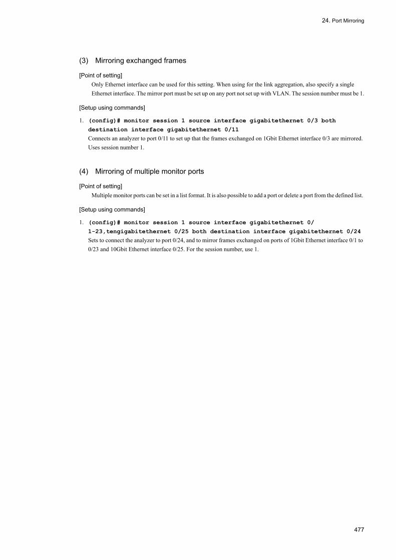
24. Port Mirroring
(3) Mirroring exchanged frames
[Point of setting]Only Ethernet interface can be used for this setting. When using for the link aggregation, also specify a single Ethernet interface. The mirror port must be set up on any port not set up with VLAN. The session number must be 1.
[Setup using commands]
1. (config)# monitor session 1 source interface gigabitethernet 0/3 both
destination interface gigabitethernet 0/11
Connects an analyzer to port 0/11 to set up that the frames exchanged on 1Gbit Ethernet interface 0/3 are mirrored. Uses session number 1.
(4) Mirroring of multiple monitor ports
[Point of setting]Multiple monitor ports can be set in a list format. It is also possible to add a port or delete a port from the defined list.
[Setup using commands]
1. (config)# monitor session 1 source interface gigabitethernet 0/
1-23,tengigabitethernet 0/25 both destination interface gigabitethernet 0/24
Sets to connect the analyzer to port 0/24, and to mirror frames exchanged on ports of 1Gbit Ethernet interface 0/1 to 0/23 and 10Gbit Ethernet interface 0/25. For the session number, use 1.
477

24. Port Mirroring
478

Appendix
Appendix A Conformed Standards
479

Appendix A. Conformed Standards
Appendix A Conformed Standards
Appendix A.1 Diff-servTable A-1: Conformed Standard and Recommendation for Diff-serv
Appendix A.2 IEEE802.1XTable A-2: Conformed Standard and Recommendation for IEEE802.1X
Appendix A.3 VRRPTable A-3: Conformed Standard and Recommendation for VRRP
Appendix A.4 IEEE802.3ah/UDLDTable A-4: Conformed Standard and Recommendation for IEEE802.3ah/UDLD
Standard No. (Issued Date) Standard Name
RFC 2474 (Dec. 1998) Definition of the Differentiated Services Field(DS Field) in the IPv4 and IPv6 Headers
RFC 2475 (Dec. 1998) An Architecture for Differentiated Services
RFC 2597 (Jun. 1999) Assured Forwarding PHB Group
RFC 2598 (Jun. 1999) An Expedited Forwarding PHB
Standard No. (Issued Date) Standard Name
IEEE802.1X (Jun. 2001) Port-Based Network Access Control
RFC 2284 (Mar. 1998) PPP Extensible Authentication Protocol (EAP)
RFC 2865 (Jun. 2000) Remote Authentication Dial In User Service (RADIUS)
RFC 2866 (Jun. 2000) RADIUS Accounting
RFC 2869 (Jun. 2000) RADIUS Extensions
RFC 3579 (Sep. 2003) RADIUS Support For Extensible Authentication Protocol (EAP)
RFC 3580 (Sep. 2003) IEEE 802.1X Remote Authentication Dial In User Service (RADIUS) Usage Guidelines
Standard No. (Issued Date) Standard Name
RFC 2787 (Jun. 1999) Definitions of Managed Objects for the Virtual Router Redundancy Protocol
RFC 3768 (Apr. 2004) Virtual Router Redundancy Protocol
draft-ietf-vrrp-ipv6-spec-02.txt(Mar. 2002)
Virtual Router Redundancy Protocol for IPv6
draft-ietf-vrrp-ipv6-spec-07.txt(Oct. 2004)
Virtual Router Redundancy Protocol for IPv6
draft-ietf-vrrp-unified-mib-04.txt(Sep. 2005)
Definitions of Managed Objects for the VRRP over IPv4 and IPv6
Standard No. (Issued Date) Standard Name
IEEE802.3ah (Sep. 2004) Part 3: Carrier Sense Multiple Access with Collision Detection (CSMA/CD) Access Method and Physical Layer SpecificationsAmendment: Media Access Control Parameters, Physical Layers, and Management Parameters for Subscriber Access Networks
480

Appendix A. Conformed Standards
Appendix A.5 SNMPTable A-5: Conformed Standard and Recommendation for SNMP
Standard No. (Issued Date) Standard Name
RFC 1155 (May 1990) Structure and Identification of Management Information for TCP/IP-based Internets
RFC 1157 (May 1990) A Simple Network Management Protocol (SNMP)
RFC 1213 (Mar. 1991) Management Information Base for Network Management of TCP/IP-based internets: MIB-II
RFC 1354 (Jul. 1992) IP Forwarding Table MIB
RFC 1493 (Jun. 1993) Definitions of Managed Objects for Bridges
RFC 1525 (Sep. 1993) Definitions of Managed Objects for Source Routing Bridges
RFC 1643 (Jul. 1994) Definitions of Managed Objects for the Ethernet-like Interface Types
RFC 1657 (Jul. 1994) Definitions of Managed Objects for the Fourth Version of the Border Gateway Protocol (BGP-4) using SMIv2
RFC 1757 (Feb. 1995) Remote Network Monitoring Management Information Base
RFC 1850 (Nov. 1995) OSPF Version2 Management Information Base
RFC 1901 (Jan. 1996) Introduction to Community-based SNMPv2
RFC 1902 (Jan. 1996) Structure of Management Information for Version 2 of the Simple Network Management Protocol (SNMPv2)
RFC 1903 (Jan. 1996) Textual Conventions for Version 2 of the Simple Network Management Protocol (SNMPv2)
RFC 1904 (Jan. 1996) Conformance Statements for Version 2 of the Simple Network Management Protocol (SNMPv2)
RFC 1905 (Jan. 1996) Protocol Operations for Version 2 of the Simple Network Management Protocol (SNMPv2)
RFC 1906 (Jan. 1996) Transport Mappings for Version 2 of the Simple Network Management Protocol (SNMPv2)
RFC 1907 (Jan. 1996) Management Information Base for Version 2 of the Simple Network Management Protocol (SNMPv2)
RFC 1908 (Jan. 1996) Coexistence between Version 1 and Version 2 of the Internet-standard Network Management Framework
RFC 2233 (Nov. 1997) The Interfaces Group MIB using SMIv2
RFC 2452 (Dec. 1998) IP Version 6 Management Information Base for the Transmission Control Protocol
RFC 2454 (Dec. 1998) IP Version 6 Management Information Base for the User Datagram Protocol
RFC 2465 (Dec. 1998) Management Information Base for IP Version 6: Textual Conventions and General Group
RFC 2466 (Dec. 1998) Management Information Base for IP Version 6: ICMPv6 Group
RFC 2578 (Apr. 1999) Structure of Management Information Version 2 (SMIv2)
RFC 2579 (Apr. 1999) Textual Conventions for SMIv2
RFC 2580 (Apr. 1999) Conformance Statements for SMIv2
RFC 3410 (Dec. 2002) Introduction and Applicability Statements for Internet Standard Management Framework
RFC 3411 (Dec. 2002) An Architecture for Describing Simple Network Management Protocol (SNMP) Management Frameworks
RFC 3412 (Dec. 2002) Message Processing and Dispatching for the Simple Network Management Protocol (SNMP)
RFC 3413 (Dec. 2002) Simple Network Management Protocol (SNMP) Applications
481

Appendix A. Conformed Standards
Appendix A.6 SYSLOGTable A-6: Conformed Standard and Recommendation for SYSLOG
Appendix A.7 sFlowTable A-7: Conformed Standard and Recommendation for sFlow
Appendix A.8 LLDPTable A-8: Conformed Standard and Recommendation for LLDP
RFC 3414 (Dec. 2002) User-based Security Model (USM) for version 3 of the Simple Network Management Protocol (SNMPv3)
RFC 3415 (Dec. 2002) View-based Access Control Model (VACM) for the Simple Network Management Protocol (SNMP)
RFC 3416 (Dec. 2002) Version 2 of the Protocol Operations for the Simple Network Management Protocol (SNMP)
RFC 3417 (Dec. 2002) Transport Mappings for the Simple Network Management Protocol (SNMP)
RFC 3418 (Dec. 2002) Management Information Base (MIB) for the Simple Network Management Protocol (SNMP)
RFC 3584 (Aug. 2003) Coexistence between Version 1, Version 2, and Version 3 of the Internet- standard Network Management Framework
RFC 3621 (Dec. 2003) Power Ethernet MIB
Standard No. (Issued Date) Standard Name
RFC 3164 (Aug. 2001) The BSD syslog Protocol
Standard No. (Issued Date) Standard Name
RFC 3176 (Sep. 2001) InMon Corporation's sFlow: A Method for Monitoring Traffic in Switched and Routed Networks
Standard No. (Issued Date) Standard Name
IEEE802.1AB/D6.0 (Oct. 2003) Draft Standard for Local and Metropolitan Networks: Station and Media Access Control - Connectivity Discovery
Standard No. (Issued Date) Standard Name
482
Index
A
alarm group 425Application example of LLDP 456ARP and NDP responses with virtual MAC address 333Attribute names used for authentication 109Attributes supported by RADIUS accounting 111Authentication mode options 117, 272Authentication modes 113, 269, 273, 274, 275, 279, 281Authentication sub-mode 116, 271, 277Automatic switch back and inhibiting it 334
B
Bandwidth monitoring 43Basic authentication mode 113, 270Basic configuration of IEEE 802.1X 131Basic IEEE 802.1X configuration 108
C
Cause of disconnect in Acct-Terminate-Cause 112Changing authentication state of IEEE 802.1X 142Chassis ID (system identifier) 457Coexistence of IEEE 802.1X and other functions 123, 290commands used to configure uplink redundancy 386Configuration [VRRP] 342Configuration and operation of GSRP 319Configuration and operation of IEEE 802.1X 129Configuration example for port authentication 114, 268, 269, 270, 272, 273, 274, 275, 276, 277, 282, 286, 287, 288Configuration example for VLAN authentication (dynamic) with inapplicable terminal 117Configuration example for VLAN authentication (static) with inapplicable port 118Configuration example of network using filtering function 2Configuration of the uplink failover extended function 363Correlation between authentication modes and options 113
D
Discard control 73
E
Error status code 420event group 425
Example of a MIB request and reply from an IPv4/IPv6 SNMP manager 411Example of obtaining MIB 410Example of trap 411
F
Failure detection mechanism for VRRP 333File for authentication error messages 226Filtering 1Flow control 31Flow detection 32Forced reauthentication 142
G
General description of GSRP 293General description of IEEE 802.1X 10⁷, 267General description of QoS control 23, 77General Description of uplink-failover extended function 359GetBulkRequest operation 416GetNextRequest operation 416GetRequest operation 415
H
history group 424
I
IEEE 802.1X overview 108, 268IEEE 820.1X configuration with an L2 switch placed between the terminals and the LANSW module 109IEEE802.3ah/UDLD 393Index 414Information supported by CDP 466Information supported by LLDP 456Information supported by OADP 465Initializing authentication state 142Item/specification supported by OADP 465
L
L2 Loop Detection 399List of "subtype" of Chassis ID 457List of "subtype" of Port ID 457List of configuration commands used for sflow statistics 446List of GSRP configuration commands 320
483

Index
List of GSRP operation commands 328List of IEEE802.3ah/OAM function operation commands 397List of IEEE802.3ah/UDLD configuration commands 396List of LLDP configuration commands 460List of OADP configuration commands 468List of OADP operation commands 470List of operation commands used for sflow statistics 452List of RIP operation commands 461List of the configuration commands common to the all QoS controls 28List of the configuration commands for IEEE 802.1X functions 130List of the configuration commands for the log output 435List of the configuration commands related to SNMP/RMON 426List of the configuration commands used for the filtering 17List of the operation commands common to the all QoS controls 29List of the operation commands related to SNMP/RMON 431List of the operation commands to check for the state of the IEEE 802.1X functions 140List of the operation commands used for the filtering 22List of VRRP Configuration Commands 342List of VRRP operation commands 349List of Web authentication configuration commands 184List of Web authentication operation commands 214Lists the storm control configuration commands 391LLDP 455Log output 433
M
MAC and IP addresses of virtual router 332MAC Authentication 235Marker 51MIB structure 413Mirror port 474Mirroring 474Mirroring received frames 474Mirroring transmitted frames 474Monitor port 474
N
Network management 410Network management using SNMP 409Note Required When Uplink Failover is Used 355Notes on using IEEE 802.1X 124, 290, 291Notes on using LLDP 458
Notes on using OADP 466Notice on using the uplink-failover extended function 361
O
OADP 463Operation 349Operation by community 419operation commands for uplink redundancy 388Operation limitation by IP address 419Operations depending on community 419Option for switching terminal detecting operation 118, 281Option to limit the number of authentication terminals 118Organizationally-defined TLV extensions 458Other Screen Samples 229Outline of MIB 413Outline of SNMP 410Outlines of QoS control blocks 24Overview of Uplink Failover 352
P
Port authentication 113Port description (port type) 458Port ID (port identifier) 457Port mirroring 473Port mirroring configuration command list 476Positioning of marker 51Priority assignment 58Private MIB 413
Q
QoS control structure 24, 78
R
RADIUS sever connecting function 121, 284Receiving frames addressed to virtual MAC 332, 374, 376, 377, 380, 382, 384, 386Representing MIB objects 414Response when MIB cannot be set 417Restriction to operation in SNMPv3 423RMON MIB 424
S
Sending ADVERTISEMENT packets 333Sequence of EAP-request/identity for "shortcut", "disable" or"full" 120SetRequest operation 417
484

Index
Setting aging time for MAC address learning with VLAN authentication (dynamic) 124Setting authentication mode options 132Setting authentication process 135Setting exclude authentication port options 133Setting exclude authentication terminal options 132Setting of MIB access permission in SNMPv3 426Setting RADIUS server 139Setting time intervals for transmitting EAP-Request/ID frame 137Setting Uplink-Failover 357Setup for dynamic assignment with VLAN authentication (dynamic) 121Setup for function requiring reauthentication of terminal 135Setup for latency time until resuming authentication after failing authentication 137Setup for limiting terminals to authenticate 133Setup for resending EAP-Request frame 135Setup for shutdown time when more than one terminal submitting authentication request 138Setup for suppressing authentication request from terminal 136Setup for switchover between terminal detecting actions 134Setup server-timeout timer for response from authentication serve 138sflow statistics (flow statistics) function 437Shaper 66SNMP agent 410SNMP engine 412SNMP entity 412SNMP operation error status code 419SNMPv1/SNMPv2C operation 415SNMPv3 operation 420Standard MIB 413statistics group 424Storm control 373, 389Support specifications [LLDP] 456Support specifications [OADP] 465Supported authentication algorithms 111Supported MIBs 414System description (system type) 458System name (system name) 458
T
Tag unique to Web Authentication 228Terminal requested reauthentication suppressing function 120, 284Time-to-Live (time over which information is held) 457Transmission control 65
Trap 423Trap format 424Trap overview 423
U
uplink port pair 374uplink-failover 351User authentication and privacy function 412
V
VLAN authentication (dynamic) 114VLAN authentication (static) 114VRRP 331VRRP Overview 332VRRP polling 337
W
Web authentication 143
485

Index
MK-99COM090-01 86