Embed Size (px)
Citation preview
Computational study of the generation of crystal defects in a bcc metal target irradiatedby short laser pulses
Zhibin Lin, Robert A. Johnson, and Leonid V. Zhigilei*Department of Materials Science and Engineering, University of Virginia, 395 McCormick Road, Charlottesville,
Virginia 22904-4745, USA�Received 22 February 2008; revised manuscript received 10 May 2008; published 16 June 2008�
The generation of crystal defects in a Cr target irradiated by a short, 200 fs, laser pulse is investigated incomputer simulations performed with a computational model that combines the classical molecular dynamicsmethod with a continuum description of the laser excitation of conduction band electrons, electron-phononcoupling, and electron heat conduction. Interatomic interactions are described by the embedded atom method�EAM� potential with a parametrization designed for Cr. The potential is tested by comparing the properties ofthe EAM Cr material with experimental data and predictions of density functional theory calculations. Thesimulations are performed at laser fluences close to the threshold for surface melting. Fast temperature varia-tion and strong thermoelastic stresses produced by the laser pulse are causing surface melting and epitaxialresolidification, transient appearance of a high density of stacking faults along the �110� planes, and generationof a large number of point defects �vacancies and self-interstitials�. The stacking faults appear as a result ofinternal shifts in the crystal undergoing a rapid uniaxial expansion in the direction normal to the irradiatedsurface. The stacking faults are unstable and disappear shortly after the laser-induced tensile stress wave leavesthe surface region of the target. Thermally activated generation of vacancy-interstitial pairs during the initialtemperature spike and quick escape of highly mobile self-interstitials to the melting front or the free surface ofthe target, along with the formation of vacancies at the solid-liquid interface during the fast resolidificationprocess, result in a high density of vacancies, on the order of 10−3 per lattice site, created in the surface regionof the target. The strong supersaturation of vacancies can be related to the incubation effect in multipulse laserablation/damage and should play an important role in mixing/alloying of multicomponent or composite targets.
DOI: 10.1103/PhysRevB.77.214108 PACS number�s�: 61.80.Ba, 02.70.Ns, 64.70.D�, 61.80.Az
I. INTRODUCTION
Surface modification by laser irradiation is in the core ofmany modern processing and fabrication techniques, includ-ing, e.g., laser surface alloying, annealing, and hardening.1–4
The improvement of surface properties is achieved by struc-tural and compositional modification of a surface layerthrough the formation of metastable phases, grain refine-ment, generation/annealing of crystal defects, and redistribu-tion of the alloying elements. Recent progress in the devel-opment of accessible sources of short �picosecond andfemtosecond� laser pulses opens up new possibilities for sur-face modification with high accuracy and spatial resolution.The shallow depths of the laser energy deposition and steeptemperature gradients, typically produced by the short pulselaser irradiation, can result in the confinement of the laser-induced structural modifications within a surface layer assmall as tens to hundreds of nanometers.5–8 The small size ofthe laser-modified zone makes characterization of laser-induced structural changes challenging and, at the same time,increases the importance of understanding of the nucleation,mobility, interactions, and stability of individual crystal de-fects and their ensembles.
With a quickly expanding range of time and length scalesaccessible for molecular dynamics �MD� simulations �sys-tems containing �106–107 atoms, with sizes on the order ofhundreds of nanometers, can be simulated fornanoseconds9,10�, the atomistic computer modeling has agood potential of revealing the mechanisms of laser-inducedphase and structural transformations. Indeed, MD simula
tions have been successfully applied for investigation of themicroscopic mechanisms of laser melting,11–13 photome-chanical spallation,14,15 and ablation10,16–20 of metal targets.A detailed analysis of the crystal defects introduced by shortpulse irradiation, however, has not been performed in MDsimulations so far and the question on the atomic-levelmechanisms responsible for the generation and evolution ofdefect configurations in laser materials processing remainslargely unexplored.
In this paper we present the results of MD simulations ofshort pulse laser interaction with a body-centered-cubic �bcc�metal, Cr. The laser fluences used in the simulations are cho-sen to be close to the threshold for the onset of surface melt-ing and the main focus of the paper is on the detailed analy-sis of the crystal defects generated in the surface region ofthe irradiated bulk target. A long term evolution of subsur-face defect configurations is studied and implications forpractical applications of nonablative laser surface modifica-tion are discussed. A brief description of the computationalmodel used in the simulations is given below, in Sec. II. Aparametrization of a computationally efficient embeddedatom method �EAM� potential for Cr as well as the physicalproperties of the model Cr material predicted by the potentialare presented in Sec. III. The results of the simulations of atransient surface melting and generation of crystal defects inthe surface region of a Cr target irradiated by a femtosecondlaser pulse are presented in Sec. IV and summarized in Sec.V.
PHYSICAL REVIEW B 77, 214108 �2008�
1098-0121/2008/77�21�/214108�15� ©2008 The American Physical Society214108-1
II. COMPUTATIONAL MODEL FOR LASERINTERACTIONS WITH A Cr TARGET
The simulations of short pulse laser irradiation of a bulkCr target are performed with a computational model thatcombines the classical MD method with a continuum de-scription of the laser excitation and subsequent relaxation ofthe conduction band electrons.11 The model is based on well-known two-temperature model �TTM�,21 which describes thetime evolution of the lattice and electron temperatures bytwo coupled nonlinear differential equations. In the com-bined model, the MD method substitutes the TTM equationfor the lattice temperature in the surface region of the target,where the laser-induced structural transformations are ex-pected to take place. The diffusion equation for the electrontemperature is solved by a finite difference method simulta-neously with MD integration of the equations of motion ofatoms. The electron temperature enters a coupling term thatis added to the MD equations of motion to account for theenergy exchange between the electrons and the lattice. Thecells in the finite difference discretization are related to thecorresponding volumes of the MD system and the local lat-tice temperature is defined for each cell from the averagekinetic energy of thermal motion of atoms.
The hybrid atomistic-continuum model, briefly discussedabove, combines the advantages of TTM and MD methods.TTM provides an adequate description of the laser energydeposition into the electronic system, energy exchange be-tween the electrons and phonons, and fast electron heat con-duction in metals, whereas the MD representation of the sur-face region of the target enables atomic-level investigationsof laser-induced structural and phase transformations. A com-plete description of the TTM-MD model is givenelsewhere.11 Below we provide the details of the computa-tional setup designed for the simulation of laser interactionwith a bulk Cr target.
The MD part of the TTM-MD model represents the top100 nm surface region of the Cr target and is composed of630 000 atoms initially arranged in a bcc crystallite with di-mensions of 8�8�100 nm3. Periodic boundary conditionsare imposed in the directions parallel to the �100� free sur-face of the target. At the bottom of the MD computationalcell, a dynamic nonreflecting boundary condition22,23 is ap-plied to account for the propagation of the laser-inducedpressure wave from the surface region of the target repre-sented by the MD method to the continuum part of themodel. The energy carried away by the pressure wave ismonitored, allowing for control over the total energy conser-vation in the combined model. In the continuum part of themodel, beyond the MD region, the electron heat conductionand the energy exchange between the electrons and the lat-tice are described by the conventional TTM. The size of thecontinuum �TTM� region is chosen to be 500 nm, so that nosignificant changes in the electron and lattice temperaturesare observed at the bottom of the continuum region duringthe time of the simulations.
The thermal and elastic properties of the target material,such as the lattice heat capacity, elastic moduli, coefficient ofthermal expansion, melting temperature, volume and entropyof melting and vaporization, etc., are all defined by the inter-
atomic interaction potential, described in this work by EAMin the form presented in Sec. III. The parameters used for Crin the TTM equation for the electron temperature are as fol-lows. The electronic heat capacity is Ce=�Te, with �=194 J m−3 K−2,24 the electron-phonon coupling constant isG=4.2�1017 W m−3 K−1,25 and the dependence of the elec-tron thermal conductivity on the electron and lattice tempera-tures is described as Ke=K0Te /Tl, withK0=94 W m−1 K−1.24 Irradiation by a 200 fs laser pulse isrepresented through a source term with a Gaussian temporalprofile and exponential attenuation of laser intensity withdepth under the surface �Beer–Lambert law� added to theTTM equation for the electron temperature. An optical pen-etration depth of 8.9 nm at a laser wavelength of 400 nm�Ref. 26� is assumed in the simulations and the absorbedlaser fluence rather than the incident fluence is used in thediscussion of the simulation results. Before applying laserirradiation, the whole computational system is equilibrated at300 K.
III. EMBEDDED ATOM METHOD INTERATOMICPOTENTIAL FOR Cr
Several potentials based on the modified embedded atommethod �MEAM� �Refs. 27–29� have been suggested for bcctransition metals. The parametrizations of MEAM includeCr, which features a negative Cauchy pressure �CP� at lowtemperatures. Consideration of the angular dependence in theinteratomic interactions, however, complicates the imple-mentation of MEAM potentials and makes large-scale MDsimulations computationally expensive. In this section wepresent a reformulation of the EAM potential of Johnson andco-workers30,31 for Cr that provides an attractive alternativeto MEAM. With a simple analytical functional form and theabsence of explicit angular terms, the potential is easy toimplement and computationally efficient, making it appropri-ate for MD simulations that involve large numbers of atoms.Below, the EAM potential and the parametrization for Cr aredescribed. Some of the physical properties of the modelEAM Cr material are calculated and related to the experi-mental data and the predictions of density functional theory�DFT� calculations.
In the EAM formalism, the total potential energy of asystem of N atoms is defined as
Epot = �i=1
N
Ei =1
2�i=1
N
�j=1
j�i
N
�ij�rij� + �i=1
N
Fi��i� , �1�
where Ei is the potential energy of an atom i, ��rij� is thepair energy term defined as a function of the interatomicdistance rij between atoms i and j, and Fi��i� is the many-body embedding energy term defined as a function of thelocal electron density, �i, at the position of atom i. The localelectron density is calculated as a linear sum of the partialelectron density contributions from the neighboring atoms,
LIN, JOHNSON, AND ZHIGILEI PHYSICAL REVIEW B 77, 214108 �2008�
214108-2
�i = �j=1
j�i
N
f j�rij� , �2�
where f j�rij� is the contribution from atom j to the electrondensity at the site of the atom i.
The functional form of the EAM Cr is similar to the onesuggested in Ref. 31. The pair energy term is defined as
��r� =
A exp�− �� r
re− 1
1 + � r
re− �20 −
B exp�− �� r
re− 1
1 + � r
re+ 20 ,
�3�
the electron density function is
f�r� =
fe exp�− �� r
re− 1
1 + � r
re− 20 , �4�
and the embedding energy function is represented by threeequations defining the function in different electron densityranges and having matching values and slopes at the twojunctions,
F��� = �i=0
3
Fi� �
0.85�e− 1i
, � 0.85�e,
F��� = �i=0
3
Fmi� �
�e− 1i
, 0.85�e � 1.15�e,
F��� = Fn�1 − � ln� �
�s� �
�s�
, � � 1.15�e. �5�
The parameters of the potential for Cr are given in TableI. They are obtained by fitting to the experimental equilib-rium lattice constant of 2.88 Å,24 the cohesive energy of4.10 eV,24 the vacancy formation energy of 2.08 eV,32 thebulk modulus B= �C11+2C12� /3 of 194.8 GPa,33 the Voigtaverage shear modulus G= �3C44+2C�� /5 of 123 GPa,33 andthe anisotropy ratio C44 /C� of 0.68,33 where C44 and C�= �C11−C12� /2 are the two shear moduli of the cubic crystal.
There is no explicit cutoff distance in the potential functions,but the pair energy term and the electron density function arevanishing beyond the third neighbor shell in the Cr bcc struc-ture �the contribution from the fourth neighbors to the inter-action energy is 2 orders of magnitude smaller than that fromthe third neighbors�.
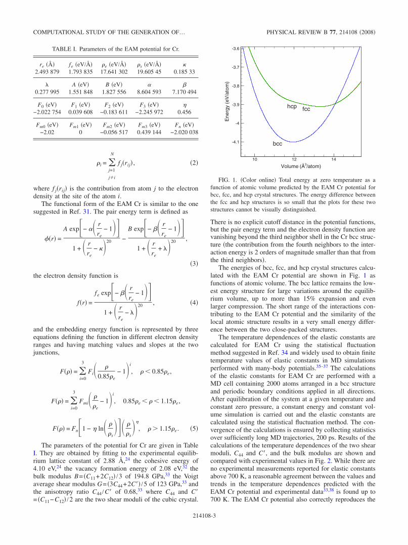
The energies of bcc, fcc, and hcp crystal structures calcu-lated with the EAM Cr potential are shown in Fig. 1 asfunctions of atomic volume. The bcc lattice remains the low-est energy structure for large variations around the equilib-rium volume, up to more than 15% expansion and evenlarger compression. The short range of the interactions con-tributing to the EAM Cr potential and the similarity of thelocal atomic structure results in a very small energy differ-ence between the two close-packed structures.
The temperature dependences of the elastic constants arecalculated for EAM Cr using the statistical fluctuationmethod suggested in Ref. 34 and widely used to obtain finitetemperature values of elastic constants in MD simulationsperformed with many-body potentials.35–37 The calculationsof the elastic constants for EAM Cr are performed with aMD cell containing 2000 atoms arranged in a bcc structureand periodic boundary conditions applied in all directions.After equilibration of the system at a given temperature andconstant zero pressure, a constant energy and constant vol-ume simulation is carried out and the elastic constants arecalculated using the statistical fluctuation method. The con-vergence of the calculations is ensured by collecting statisticsover sufficiently long MD trajectories, 200 ps. Results of thecalculations of the temperature dependences of the two shearmoduli, C44 and C�, and the bulk modulus are shown andcompared with experimental values in Fig. 2. While there areno experimental measurements reported for elastic constantsabove 700 K, a reasonable agreement between the values andtrends in the temperature dependences predicted with theEAM Cr potential and experimental data33,38 is found up to700 K. The EAM Cr potential also correctly reproduces the
TABLE I. Parameters of the EAM potential for Cr.
re ��2.493 879
fe �eV/�1.793 835
�e �eV/�17.641 302
�s �eV/�19.605 45
�0.185 33
0.277 995
A �eV�1.551 848
B �eV�1.827 556
�8.604 593
�7.170 494
F0 �eV�−2.022 754
F1 �eV�0.039 608
F2 �eV�−0.183 611
F3 �eV�−2.245 972
�0.456
Fm0 �eV�−2.02
Fm1 �eV�0
Fm2 �eV�−0.056 517
Fm3 �eV�0.439 144
Fn �eV�−2.020 038
Volume (Å3/atom)
Ene
rgy
(eV
/ato
m)
10 12 14
-4.1
-4
-3.9
-3.8
-3.7
-3.6
hcp
bcc
fcc
FIG. 1. �Color online� Total energy at zero temperature as afunction of atomic volume predicted by the EAM Cr potential forbcc, fcc, and hcp crystal structures. The energy difference betweenthe fcc and hcp structures is so small that the plots for these twostructures cannot be visually distinguished.
COMPUTATIONAL STUDY OF THE GENERATION OF… PHYSICAL REVIEW B 77, 214108 �2008�
214108-3
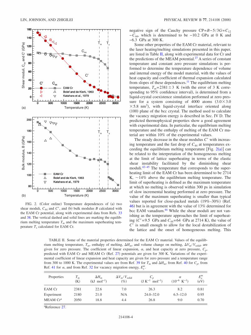
negative sign of the Cauchy pressure CP=B−5 /3G=C12−C44, which is determined to be −10.2 GPa at 0 K and−6.3 GPa at 300 K.
Some other properties of the EAM Cr material, relevant tothe laser heating/melting simulations presented in this paper,are listed in Table II, along with experimental data for Cr andthe predictions of the MEAM potential.27 A series of constanttemperature and constant zero pressure simulations is per-formed to determine the temperature dependence of volumeand internal energy of the model material, with the values ofheat capacity and coefficient of thermal expansion calculatedfrom slopes of these dependences.11 The equilibrium meltingtemperature, Tm=2381 3 K �with the error of 3 K corre-sponding to 95% confidence interval�, is determined from aliquid-crystal coexistence simulation performed at zero pres-sure for a system consisting of 4000 atoms �3.0�3.0�5.8 nm3�, with liquid-crystal interface oriented along�100� plane of the bcc crystal. The method used to calculatethe vacancy migration energy is described in Sec. IV D. Thepredicted thermophysical properties show a good agreementwith experimental data. In particular, the equilibrium meltingtemperature and the enthalpy of melting of the EAM Cr ma-terial are within 10% of the experimental values.
The steady decrease in the shear modulus C� with increas-ing temperature and the fast drop of C44 at temperatures ex-ceeding the equilibrium melting temperature �Fig. 2�a�� canbe related to the interpretation of the homogeneous meltingat the limit of lattice superheating in terms of the elasticshear instability facilitated by the diminishing shearmoduli.42–45 The temperature that corresponds to the super-heating limit of the EAM Cr has been determined to be 2714K, �14% above the equilibrium melting temperature. Thelimit of superheating is defined as the maximum temperatureat which no melting is observed within 300 ps in simulationof slow incremental heating performed at zero pressure. Thevalue of the maximum superheating is smaller than typicalvalues reported for close-packed metals �19%–30%� �Ref.46� but is in agreement with the value of 13% determined forbcc EAM vanadium.44 While the shear moduli are not van-ishing as the temperature approaches the limit of superheat-ing �C�=9.5 GPa and C44=64 GPa at 2714 K�, the value ofC� is small enough to allow for the local destabilization ofthe lattice and the onset of homogeneous melting. This
0 500 1000 1500 2000 2500 3000
0
20
40
60
80
100
120
140
160
EAM CrBolef and de Klerk, 1963Katahara et al., 1979
0 500 1000 1500 2000 2500 3000
0
20
40
60
80
100
120
140
160
EAM CrBolef and de Klerk, 1963Katahara et al., 1979
0 500 1000 1500 2000 2500 3000
0
20
40
60
80
100
120
140
160
C44C’
Temperature (K)
She
arm
odul
i,C
44an
dC
’(G
Pa)
0 500 1000 1500 2000 2500 3000
0
20
40
60
80
100
120
140
160
C44C’
C44
C’
Tm Ts
0 500 1000 1500 2000 2500 3000
80
100
120
140
160
180
200
EAM CrBolef and de Klerk, 1963Katahara et al., 1979
Temperature (K)
Bul
km
odul
us,B
(GP
a)
0 500 1000 1500 2000 2500 3000
80
100
120
140
160
180
200
EAM CrBolef and de Klerk, 1963Katahara et al., 1979
TsTm
(a)
(b)
FIG. 2. �Color online� Temperature dependences of �a� twoshear moduli, C44 and C�, and �b� bulk modulus B calculated withthe EAM Cr potential, along with experimental data from Refs. 33and 38. The vertical dashed and solid lines are marking the equilib-rium melting temperature Tm and the maximum superheating tem-perature Ts calculated for EAM Cr.
TABLE II. Some of the material properties determined for the EAM Cr material. Values of the equilib-rium melting temperature, Tm, enthalpy of melting, �Hm, and volume change on melting, �Vm /Vsolid, aregiven for zero pressure. The coefficient of linear expansion, �, and heat capacity at zero pressure, Cp,predicted with EAM Cr and MEAM Cr �Ref. 27� potentials are given for 300 K. Variations of the experi-mental coefficient of linear expansion and heat capacity are given for zero pressure and a temperature rangefrom 300 to 1000 K. The experimental values are from Ref. 39 for Tm and �Hm, from Ref. 40 for Cp, fromRef. 41 for �, and from Ref. 32 for vacancy migration energy, Ev
m.
Properties Tm
�K��Hm
�kJ mol−1��Vm /Vsolid
�%�Cp
�J K−1 mol−1��
�10−6 K−1�Ev
m
�eV�
EAM Cr 2381 22.6 7.0 26.3 8.2 0.81
Experiment 2180 21.0 N/A 24.0–32.0 6.5–12.0 0.95
MEAM Cra 2050 18.8 4.4 26.8 9.0 0.70
aReference 27.
LIN, JOHNSON, AND ZHIGILEI PHYSICAL REVIEW B 77, 214108 �2008�
214108-4
mechanism of local “mechanical” melting has been sug-gested based on the results of recent MD simulations.43,45
The generation of vacancy-interstitial pairs and the interac-tions among the point defects are likely to facilitate the gen-eration of the lattice instabilities.44,48,49 Moreover, it has beenshown in Ref. 45 that the generation of vacancy-interstitialpairs makes positive contributions to the values of the elasticmoduli, suggesting that the change in slope of the tempera-ture dependence of C� and B at high temperatures can be, atleast partially, attributed to the rapid increase in the densityof the point defects generated at temperatures approachingand exceeding the equilibrium melting temperature.
IV. TTM-MD SIMULATIONS: RESULTS AND DISCUSSION
In this section, the conditions leading to the transient andpermanent structural changes in a surface region of a Crtarget irradiated by a femtosecond laser pulse are discussedbased on the results of two large-scale TTM-MD simula-tions. The results from a simulation performed at an ab-sorbed laser fluence of 638 J /m2, just above the thresholdfor surface melting, are presented first, followed by a briefdiscussion of the second simulation performed at a lowerabsorbed fluence of 425 J /m2, when no permanent structuralchanges are observed in the target at the end of the simula-tion.
A. Laser-induced stresses, surface melting
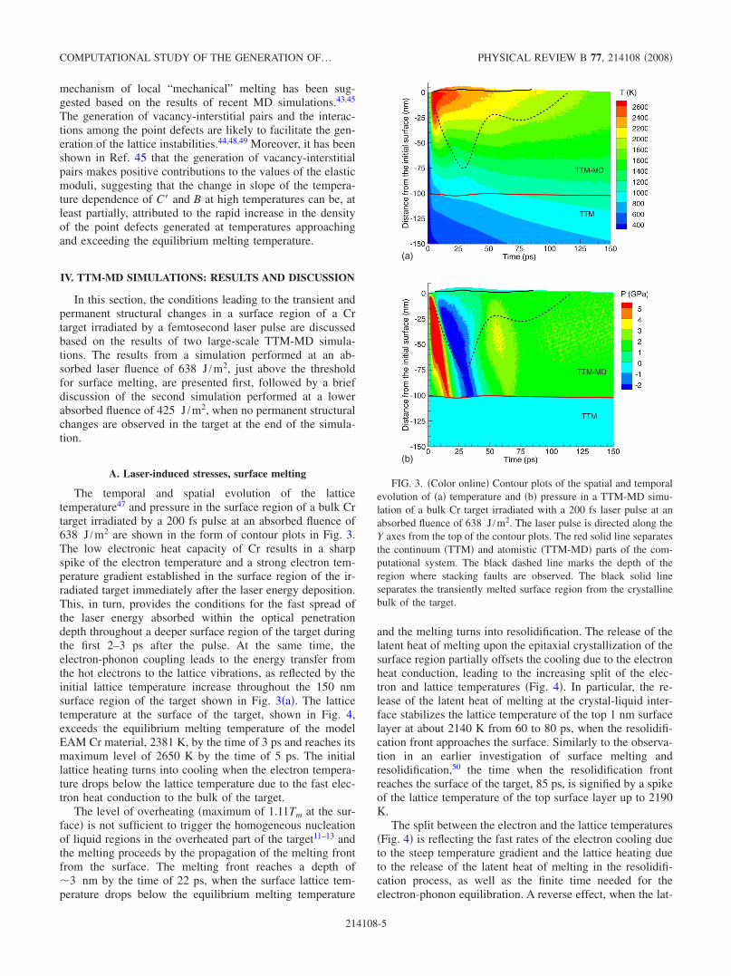
The temporal and spatial evolution of the latticetemperature47 and pressure in the surface region of a bulk Crtarget irradiated by a 200 fs pulse at an absorbed fluence of638 J /m2 are shown in the form of contour plots in Fig. 3.The low electronic heat capacity of Cr results in a sharpspike of the electron temperature and a strong electron tem-perature gradient established in the surface region of the ir-radiated target immediately after the laser energy deposition.This, in turn, provides the conditions for the fast spread ofthe laser energy absorbed within the optical penetrationdepth throughout a deeper surface region of the target duringthe first 2–3 ps after the pulse. At the same time, theelectron-phonon coupling leads to the energy transfer fromthe hot electrons to the lattice vibrations, as reflected by theinitial lattice temperature increase throughout the 150 nmsurface region of the target shown in Fig. 3�a�. The latticetemperature at the surface of the target, shown in Fig. 4,exceeds the equilibrium melting temperature of the modelEAM Cr material, 2381 K, by the time of 3 ps and reaches itsmaximum level of 2650 K by the time of 5 ps. The initiallattice heating turns into cooling when the electron tempera-ture drops below the lattice temperature due to the fast elec-tron heat conduction to the bulk of the target.
The level of overheating �maximum of 1.11Tm at the sur-face� is not sufficient to trigger the homogeneous nucleationof liquid regions in the overheated part of the target11–13 andthe melting proceeds by the propagation of the melting frontfrom the surface. The melting front reaches a depth of�3 nm by the time of 22 ps, when the surface lattice tem-perature drops below the equilibrium melting temperature
and the melting turns into resolidification. The release of thelatent heat of melting upon the epitaxial crystallization of thesurface region partially offsets the cooling due to the electronheat conduction, leading to the increasing split of the elec-tron and lattice temperatures �Fig. 4�. In particular, the re-lease of the latent heat of melting at the crystal-liquid inter-face stabilizes the lattice temperature of the top 1 nm surfacelayer at about 2140 K from 60 to 80 ps, when the resolidifi-cation front approaches the surface. Similarly to the observa-tion in an earlier investigation of surface melting andresolidification,50 the time when the resolidification frontreaches the surface of the target, 85 ps, is signified by a spikeof the lattice temperature of the top surface layer up to 2190K.
The split between the electron and the lattice temperatures�Fig. 4� is reflecting the fast rates of the electron cooling dueto the steep temperature gradient and the lattice heating dueto the release of the latent heat of melting in the resolidifi-cation process, as well as the finite time needed for theelectron-phonon equilibration. A reverse effect, when the lat-
(a)
(b)
FIG. 3. �Color online� Contour plots of the spatial and temporalevolution of �a� temperature and �b� pressure in a TTM-MD simu-lation of a bulk Cr target irradiated with a 200 fs laser pulse at anabsorbed fluence of 638 J /m2. The laser pulse is directed along theY axes from the top of the contour plots. The red solid line separatesthe continuum �TTM� and atomistic �TTM-MD� parts of the com-putational system. The black dashed line marks the depth of theregion where stacking faults are observed. The black solid lineseparates the transiently melted surface region from the crystallinebulk of the target.
COMPUTATIONAL STUDY OF THE GENERATION OF… PHYSICAL REVIEW B 77, 214108 �2008�
214108-5
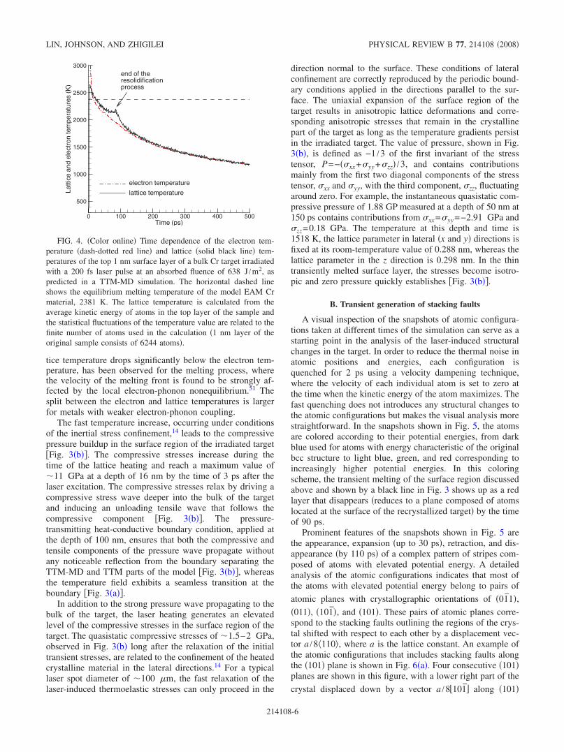
tice temperature drops significantly below the electron tem-perature, has been observed for the melting process, wherethe velocity of the melting front is found to be strongly af-fected by the local electron-phonon nonequilibrium.51 Thesplit between the electron and lattice temperatures is largerfor metals with weaker electron-phonon coupling.
The fast temperature increase, occurring under conditionsof the inertial stress confinement,14 leads to the compressivepressure buildup in the surface region of the irradiated target�Fig. 3�b��. The compressive stresses increase during thetime of the lattice heating and reach a maximum value of�11 GPa at a depth of 16 nm by the time of 3 ps after thelaser excitation. The compressive stresses relax by driving acompressive stress wave deeper into the bulk of the targetand inducing an unloading tensile wave that follows thecompressive component �Fig. 3�b��. The pressure-transmitting heat-conductive boundary condition, applied atthe depth of 100 nm, ensures that both the compressive andtensile components of the pressure wave propagate withoutany noticeable reflection from the boundary separating theTTM-MD and TTM parts of the model �Fig. 3�b��, whereasthe temperature field exhibits a seamless transition at theboundary �Fig. 3�a��.
In addition to the strong pressure wave propagating to thebulk of the target, the laser heating generates an elevatedlevel of the compressive stresses in the surface region of thetarget. The quasistatic compressive stresses of �1.5–2 GPa,observed in Fig. 3�b� long after the relaxation of the initialtransient stresses, are related to the confinement of the heatedcrystalline material in the lateral directions.14 For a typicallaser spot diameter of �100 �m, the fast relaxation of thelaser-induced thermoelastic stresses can only proceed in the
direction normal to the surface. These conditions of lateralconfinement are correctly reproduced by the periodic bound-ary conditions applied in the directions parallel to the sur-face. The uniaxial expansion of the surface region of thetarget results in anisotropic lattice deformations and corre-sponding anisotropic stresses that remain in the crystallinepart of the target as long as the temperature gradients persistin the irradiated target. The value of pressure, shown in Fig.3�b�, is defined as −1 /3 of the first invariant of the stresstensor, P=−��xx+�yy +�zz� /3, and contains contributionsmainly from the first two diagonal components of the stresstensor, �xx and �yy, with the third component, �zz, fluctuatingaround zero. For example, the instantaneous quasistatic com-pressive pressure of 1.88 GP measured at a depth of 50 nm at150 ps contains contributions from �xx=�yy =−2.91 GPa and�zz=0.18 GPa. The temperature at this depth and time is1518 K, the lattice parameter in lateral �x and y� directions isfixed at its room-temperature value of 0.288 nm, whereas thelattice parameter in the z direction is 0.298 nm. In the thintransiently melted surface layer, the stresses become isotro-pic and zero pressure quickly establishes �Fig. 3�b��.
B. Transient generation of stacking faults
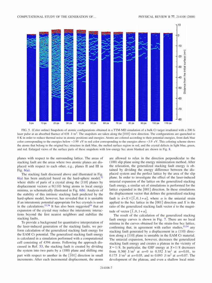
A visual inspection of the snapshots of atomic configura-tions taken at different times of the simulation can serve as astarting point in the analysis of the laser-induced structuralchanges in the target. In order to reduce the thermal noise inatomic positions and energies, each configuration isquenched for 2 ps using a velocity dampening technique,where the velocity of each individual atom is set to zero atthe time when the kinetic energy of the atom maximizes. Thefast quenching does not introduces any structural changes tothe atomic configurations but makes the visual analysis morestraightforward. In the snapshots shown in Fig. 5, the atomsare colored according to their potential energies, from darkblue used for atoms with energy characteristic of the originalbcc structure to light blue, green, and red corresponding toincreasingly higher potential energies. In this coloringscheme, the transient melting of the surface region discussedabove and shown by a black line in Fig. 3 shows up as a redlayer that disappears �reduces to a plane composed of atomslocated at the surface of the recrystallized target� by the timeof 90 ps.
Prominent features of the snapshots shown in Fig. 5 arethe appearance, expansion �up to 30 ps�, retraction, and dis-appearance �by 110 ps� of a complex pattern of stripes com-posed of atoms with elevated potential energy. A detailedanalysis of the atomic configurations indicates that most ofthe atoms with elevated potential energy belong to pairs of
atomic planes with crystallographic orientations of �01̄1�,�011�, �101̄�, and �101�. These pairs of atomic planes corre-spond to the stacking faults outlining the regions of the crys-tal shifted with respect to each other by a displacement vec-tor a /8 110�, where a is the lattice constant. An example ofthe atomic configurations that includes stacking faults alongthe �101� plane is shown in Fig. 6�a�. Four consecutive �101�planes are shown in this figure, with a lower right part of the
crystal displaced down by a vector a /8�101̄� along �101�
Time (ps)
Latt
ice
and
elec
tron
tem
pera
ture
s(K
)
0 100 200 300 400 500
500
1000
1500
2000
2500
3000end of theresolidificationprocess
electron temperature
lattice temperature
FIG. 4. �Color online� Time dependence of the electron tem-perature �dash-dotted red line� and lattice �solid black line� tem-peratures of the top 1 nm surface layer of a bulk Cr target irradiatedwith a 200 fs laser pulse at an absorbed fluence of 638 J /m2, aspredicted in a TTM-MD simulation. The horizontal dashed lineshows the equilibrium melting temperature of the model EAM Crmaterial, 2381 K. The lattice temperature is calculated from theaverage kinetic energy of atoms in the top layer of the sample andthe statistical fluctuations of the temperature value are related to thefinite number of atoms used in the calculation �1 nm layer of theoriginal sample consists of 6244 atoms�.
LIN, JOHNSON, AND ZHIGILEI PHYSICAL REVIEW B 77, 214108 �2008�
214108-6
planes with respect to the surrounding lattice. The areas ofstacking fault are the areas where two atomic planes are dis-placed with respect to each other, e.g., planes II and III inFig. 6�a�.
The stacking fault discussed above and illustrated in Fig.6�a� has been analyzed based on the hard-sphere model,52
where shifts of parts of a crystal along the �110� planes bydisplacement vectors a /8 110� bring atoms to local energyminima, as schematically illustrated in Fig. 6�b�. Analysis ofthe stability of this intrinsic stacking fault predicted by thehard-sphere model, however, has revealed that it is unstableif an interatomic potential appropriate for bcc crystals is usedin the calculations.53,54 It has also been suggested54 that anexpansion of the crystal may reduce the interatomic interac-tions beyond the first nearest neighbors and stabilize thestacking faults.
To provide a background for quantitative interpretation ofthe laser-induced generation of the stacking faults, we per-form calculation of the generalized stacking fault energy forthe EAM Cr potential. The generalized stacking fault energyis calculated in a simulation performed with a computationalcell consisting of 4394 atoms. Following the approach dis-cussed in Ref. 53, the stacking fault is created by dividingthe system into two parts by a �100� plane and shifting one
part with respect to another in the �1̄01� direction in smallincrements. After each incremental displacement, the atoms
are allowed to relax in the direction perpendicular to the�100� slip plane using the energy minimization method. Afterthe relaxation, the generalized stacking fault energy is ob-tained by dividing the energy difference between the dis-placed system and the perfect lattice by the area of the slipplane. In order to investigate the effect of the laser-induceduniaxial expansion of the lattice on the generalized stackingfault energy, a similar set of simulations is performed for thelattice expanded in the �001� direction. In these simulationsthe displacement vector that defines the generalized stacking
fault is u� =X� �1̄ ,0 ,1+��, where � is the uniaxial strainapplied to the bcc lattice in the �001� direction and X is theratio of the generalized stacking fault vector u� to the magni-
tude of vector �1̄ ,0 ,1+��.The result of the calculation of the generalized stacking
fault energy curves is shown in Fig. 7. There are no localminima in the curves obtained for the strain-free bcc lattice,confirming that, in agreement with earlier studies,53,54 anystacking fault generated by a displacement in a 110� direc-tion along a �110� plane is unstable in the EAM Cr material.The uniaxial expansion, however, decreases the generalizedstacking fault energy and creates a plateau in the vicinity ofX�1 /8. In particular, the GSF energy at X=1 /8 decreasesfrom 0.360 J /m2 at �=0 to 0.352 J /m2 at �=0.01, to0.175 J /m2 at �=0.05, and to 0.093 J /m2 at �=0.07. Thedevelopment of the plateau, and even a shallow local mini-
FIG. 5. �Color online� Snapshots of atomic configurations obtained in a TTM-MD simulation of a bulk Cr target irradiated with a 200 fslaser pulse at an absorbed fluence of 638 J /m2. The snapshots are taken along the �010� view direction. The configurations are quenched to0 K in order to reduce thermal noise in atomic positions and energies. Atoms are colored according to their potential energies, from dark bluecolor corresponding to the energies below −3.99 eV to red color corresponding to the energies above −3.9 eV. This coloring scheme showsthe atoms that belong to the original bcc structure in dark blue, the melted surface region in red, and the crystal defects in light blue, green,and red. Enlarged views of the surface parts of these snapshots with low-energy bcc atom blanked are shown in Fig. 8.
COMPUTATIONAL STUDY OF THE GENERATION OF… PHYSICAL REVIEW B 77, 214108 �2008�
214108-7

mum observed at 7% strain, suggests that the stacking faultat X�1 /8, predicted with the hard-sphere model, can bestabilized by the laser-induced uniaxial expansion of the tar-get. Indeed, the analysis of the atomic configurations shownin Fig. 5 suggests that the uniaxial strain reaches its maxi-mum value of 6.5% by the time of 20 ps at a depth of�50 nm below the surface.
The analysis of the stacking fault energy provided aboveis consistent with the results of the simulations of laser irra-diation of a Cr target, where the transient appearance of the
stacking faults can be clearly correlated with the expansionof the lattice associated with the propagation of the tensilecomponent of the laser-induced stress wave. Indeed, thespreading of the region where the stacking faults are ob-served �shown by the dashed line in Fig. 3� follows closelythe propagation of the tensile stress wave �Fig. 3�b��. Theuniaxial expansion of the lattice in the �001� direction acti-vates multiple shifts in four out of six �110� crystallographicplanes oriented at 45° with respect to the �001� axis of ex-
pansion, namely, �01̄1�, �011�, �101̄�, and �101�. The inter-sections of these planes with the �010� view plane in Fig. 5are seen as stripes oriented in three directions �horizontal andtilted by 45° with respect to the horizontal direction�. Thestacking faults on the �110� planes start to disappear as soonas the tensile stress wave leaves the surface region and thelattice expansion partially relaxes. The second, much weakerpressure oscillation in the surface region, occurring at around40–90 ps, is also affecting the evolution of the stackingfaults, with the stacking fault region experiencing a smalladditional growth during the time interval when the latticeexpands from 65 to 90 ps �see Fig. 3�b� and snapshots for60–90 ps in Fig. 5�. As discussed above, this additional lat-tice expansion takes place on the background of quasistaticthermoelastic stresses defined by the lateral confinement ofthe lattice and does not result in the negative pressure values.The stacking faults continue to withdraw at later times andcompletely disappear by the time of 115 ps.
The correlation between the tensile stresses and the ap-pearance of the stacking faults can be further illustrated bythe virtual absence of the stacking faults in the top �5 nmpart of the target, where the tensile stresses are low �Fig.3�b��. The stacking fault-free region can be seen in the snap-shots shown in Fig. 5, as well as in the enlarged views of thesurface part of the irradiated target, shown in Fig. 8, wherethe low-energy bcc atoms are blanked in order to expose the
crystal defects and the view direction is changed to �1̄1̄0�.
(b) (c) (d) (e)
(a)
FIG. 6. �Color online� Close up on the atomic arrangements thatcorrespond to the crystal defects observed in the TTM-MD simula-tion and identified in Fig. 8. A region marked by “A” in a snapshotshown for 100 ps in Fig. 8 is illustrated in �a�, where four consecu-tive �101� planes are shown. This region includes a part �lower
right� of the crystal displaced down by a vector a /8�101̄� along a�101� plane with respect to the original crystal structure. The dis-placement leads to the formation of stacking faults that show up inthe figure as pairs of atomic planes �e.g., II and III� with elevatedpotential energy. The red dashed lines mark the displaced rows ofatoms in plane �II�. This type of displacement results in the forma-tion of stacking faults along the �110� planes as illustrated by anatomic arrangement in �b�, where the displacement of a top atom�dashed circles� is shown by an arrow with respect to four atoms inthe underlying �101� plane �solid circles�. Atomic configurationsthat correspond to the defects marked by “B,” “C,” and “D” in asnapshot shown for 450 ps in Fig. 8 are illustrated in �c� a vacancy,�d� an interstitial in a 110�-dumbbell configuration, and �e� a clus-ter of four interstitials arranged in a 111�-crowdion configuration,respectively. A single �101� plane is shown in �c� and �d�, and allatoms in the vicinity of the four 111�-crowdion interstitial clusterthat have potential energy higher than −4.09 eV are shown in �e�,where the view direction is slightly tilted with respect to the �1̄11�direction. Atoms are colored according to their potential energies,from dark blue color corresponding to the energies below −3.99 eV�these atoms are blanked in Fig. 8� to red color corresponding to theenergies above −3.9 eV. The cohesive energy of the EAM Cr bcccrystal is 4.10 eV.
X
γ GS
F(J
/m2 )
0 0.2 0.4 0.6 0.8 1
0
0.5
1
1.5α = 0α = 0.01α = 0.05α = 0.07
FIG. 7. �Color online� Generalized stacking fault energy, �GSF,for the �100� slip plane in bcc EAM Cr as a function of the magni-
tude of the fault vector, u� =X� �1̄ ,0 ,1+��. The GSF curves arecalculated for different values of the uniaxial strain, �, applied tothe bcc lattice in the �001� direction. The dashed line marks thestacking fault at X=1 /8, predicted with the hard-sphere model.
LIN, JOHNSON, AND ZHIGILEI PHYSICAL REVIEW B 77, 214108 �2008�
214108-8
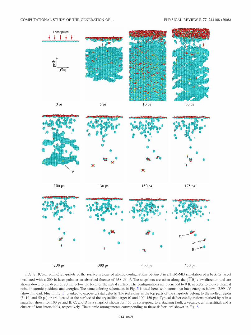
FIG. 8. �Color online� Snapshots of the surface regions of atomic configurations obtained in a TTM-MD simulation of a bulk Cr target
irradiated with a 200 fs laser pulse at an absorbed fluence of 638 J /m2. The snapshots are taken along the �1̄1̄0� view direction and areshown down to the depth of 20 nm below the level of the initial surface. The configurations are quenched to 0 K in order to reduce thermalnoise in atomic positions and energies. The same coloring scheme as in Fig. 5 is used here, with atoms that have energies below −3.99 eV�shown in dark blue in Fig. 5� blanked to expose crystal defects. The red atoms in the top parts of the snapshots belong to the melted region�5, 10, and 50 ps� or are located at the surface of the crystalline target �0 and 100–450 ps�. Typical defect configurations marked by A in asnapshot shown for 100 ps and B, C, and D in a snapshot shown for 450 ps correspond to a stacking fault, a vacancy, an interstitial, and acluster of four interstitials, respectively. The atomic arrangements corresponding to these defects are shown in Fig. 6.
COMPUTATIONAL STUDY OF THE GENERATION OF… PHYSICAL REVIEW B 77, 214108 �2008�
214108-9

C. Generation of vacancies and self-interstitials
The inspection of Fig. 8 indicates that a large number ofpoint defects are generated by the laser irradiation and manyof the defects still remain in the surface region of the targetafter the disappearance of the stacking faults. Analysis of theatomic configurations reveals that the defects are vacancies,interstitials, divacancies, and a cluster of interstitials. Withthe visualization method used in Fig. 8, when only atomswith elevated potential energy are shown in the quenchedconfigurations, each vacancy shows up as a cluster of 14atoms that includes the eight nearest neighbors and sixsecond-nearest neighbors of the missing atom. A closeup onan atomic arrangement around a vacancy is shown in Fig.6�c�, where a single �101� plane is shown. Four out of eightnearest neighbors and two out of six second-nearest neigh-bors are located in this plane and are shown in light bluecolor. The individual interstitials are found to always take a 110�-dumbbell configuration, which is illustrated in Fig.6�d�. In Fig. 8, the interstitials appear as planar crosslikeconfigurations with red atoms in the middle, oriented in oneof the �110� planes. The 110�-dumbbell configuration hasbeen predicted to be the most stable self-interstitial configu-ration in calculations performed for many bcc metals withpairwise55 and EAM �Ref. 56� potentials. The energies of therelaxed 110� and 111� self-interstitial configurations pre-dicted by the EAM Cr potential used in this work are 5.02and 5.89 eV, respectively. Recent DFT calculations57–59 pre-dict similar values for the formation energies of differentself-interstitial configurations, in the range of 5.66–5.85 eV,suggesting that 110� and 111� configurations are almostdegenerate.59 The MEAM Cr potential, however, predicts the 110�-dumbbell configuration to be the stable one, with asmaller formation energy of 3.9 eV.27
The appearance of point defects can be seen as early as 5ps after the laser pulse; e.g., two vacancy-interstitial pairscan be identified close to the surface in a snapshot shown for5 ps in Fig. 8. Due to a much higher mobility of interstitialsas compared to vacancies, most of the interstitials quicklydiffuse and escape to the melting front or the surface of thetarget, leaving behind a high concentration of vacancies inthe near-surface region. By the time of 150 ps there are onlytwo interstitials located 12.7 and 17 nm below the surfaceand one cluster of three interstitials located 13.3 nm belowthe surface. There are no interstitials by this time in the top10 nm region of the target, and the atoms of high potentialenergy �shown in red� observed in the top half of Fig. 8belong to the configurations where two vacancies are locatedclose to each other. Between 175 and 200 ps one of theinterstitials joins the cluster, increasing the number of inter-stitials in the cluster from 3 to 4. Both the three- and four-interstitial clusters have 111�-crowdion configurations, illus-trated in Fig. 8�e� for the four-interstitial cluster. Thisobservation is consistent with earlier results60–62 suggestingthat small clusters of interstitials arrange themselves into setsof 111� crowdions/dumbbells. At a sufficiently large size, a 111�-crowdion cluster can be described as a dislocation loopwith a Burgers vector a /2 111�. The high mobility of suchdislocation loops was demonstrated in a recent in situ trans-mission electron microscopy study,63 where a nanometer-
sized dislocation loop in �-Fe was shown to undergo anactive thermally activated one-dimensional diffusion at atemperature as low as 575 K.
Indeed, although the temperature at the depth of the loca-tion of the interstitial and the cluster of interstitials dropsdown to �1100 K ��0.46Tm� by the end of the simulation,both the interstitial and the cluster remain very mobile, ascan be seen from changes in the positions and orientations ofthe 110�-dumbbell interstitial and the four 111�-crowdioncluster in Fig. 8. The mechanisms of interstitial diffusionobserved in MD simulations performed for different bcc met-als include reorientation of the 110� dumbbell in one of the 111� directions followed by low-energy barrier jumps alongthe close-packed 111� direction,60,64 as well as rotation andtranslation of 110� dumbbell.55,65 While the mobility of theinterstitials and their clusters at low temperatures can bestrongly affected by relatively small variations in the valuesof the energy barriers separating different self-interstitialconfigurations, at high temperatures realized in our simula-tions �T�1100–2650 K; kBT�0.1–0.2 eV� different typesof jumps and reorientations of the interstitial configurationscan be readily activated, making the diffusion pathwaysmore complex59,66 and, at the same time, less sensitive to thedetailed energy landscape predicted with a particular inter-atomic potential.
The high mobility of the interstitial cluster observed inFig. 8 is consistent with the decrease in the migration energywith increasing cluster size reported in MD simulations per-formed with different interatomic potentials.61,62,64,65 The dif-fusion of a small interstitial cluster is typically described as acombination of a rapid one-dimensional migration along thecrowdion direction and rotations to the equivalent 111� di-rections. The frequency of the rotations is increasing withtemperature and decreasing with the size of thecluster.61,62,64,65 For the cluster of four interstitials observedin the present simulation, the temperature of the surface re-gion of the target remains sufficiently high during the time ofthe simulation to induce occasional reorientations of thecluster, resulting in a three-dimensional migration of thecluster �Fig. 8�.
The high mobility of the remaining interstitial and theinterstitial cluster suggests that they are likely to recombinewith vacancies or escape to the surface as the cooling processcontinues. The positions of the vacancies, on the other hand,become relatively static by the end of the simulation. Thedistribution of vacancies in the top 8 nm surface region ofthe target is shown in Fig. 9. There is a total of 53 vacanciesin this region, with three more vacancies located below theregion shown in the plot at 10.3, 11.2, and 15.1 nm below thesurface. Despite the high concentration of vacancies in thesurface region of the target �1.7�10−3 in a layer between 1and 5 nm below the surface�, we do not observe any ten-dency of vacancies to form clusters or small dislocationloops. Only three pairs of vacancies occupying adjacentsecond-nearest-neighbor lattice sites; one pair in fourth-nearest-neighbor lattice sites and one pair in fifth-nearest-neighbor lattice sites have been identified at 500 ps after thelaser pulse. The absence of any pronounced clustering ofvacancies can be explained by relatively low �as compared toclusters of interstitials� binding energies of divacancies and
LIN, JOHNSON, AND ZHIGILEI PHYSICAL REVIEW B 77, 214108 �2008�
214108-10
larger vacancy clusters,55,59,61,62 as well as by the high tem-perature of the surface region of the irradiated target duringthe time of the simulation �Fig. 4�.
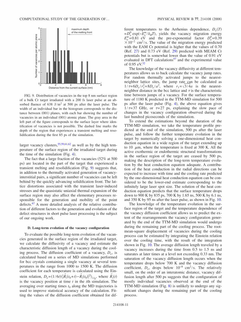
The fact that a large fraction of the vacancies �52% at 500ps� are located in the part of the target that experienced atransient melting and resolidification �Fig. 9� suggests that,in addition to the thermally activated generation of vacancy-interstitial pairs, a significant number of vacancies can be leftbehind by the quickly advancing solidification front. The lat-tice distortions associated with the transient laser-inducedstresses and the quasistatic uniaxial thermal expansion of thesurface region may also affect the elementary processes re-sponsible for the generation and mobility of the pointdefects.67 A more detailed analysis of the relative contribu-tion of different factors to the generation and evolution of thedefect structures in short pulse laser processing is the subjectof our ongoing work.
D. Long-term evolution of the vacancy configuration
To evaluate the possible long-term evolution of the vacan-cies generated in the surface region of the irradiated target,we calculate the diffusivity of a vacancy and estimate thecharacteristic diffusion length of a vacancy during the cool-ing process. The diffusion coefficient of a vacancy, Dv, iscalculated based on a series of MD simulations performedfor bcc crystals containing a single vacancy at several tem-peratures in the range from 1000 to 1500 K. The diffusioncoefficient for each temperature is calculated using the Ein-
stein relation, Dv= �1 /6t� �R� i�t0+ t�−R� i�t0��2�i,t0, where R� i�t�
is the vacancy position at time t in the ith simulation. Theaveraging over starting times t0 along the MD trajectories isused to improve statistical accuracy of the calculation. Fit-ting the values of the diffusion coefficient obtained for dif-
ferent temperatures to the Arrhenius dependence, Dv�T�=Dv
0 exp�−Evm /kBT�, yields the vacancy migration energy
Evm=0.81 eV and the pre-exponential factor Dv
0 =0.39�10−2 cm2 /s. The value of the migration energy predictedwith the EAM Cr potential is higher that the values of 0.70�Ref. 27� and 0.73 eV �Ref. 29� predicted with MEAM Crpotentials but is somewhat lower than the value of 0.91 eVevaluated in DFT calculations57 and the experimental valueof 0.95 eV.32
The knowledge of the vacancy diffusivity at different tem-peratures allows us to back calculate the vacancy jump rates.For random thermally activated jumps to the nearest-neighbor lattice sites, the jump rate can be calculated as1 /�=6Dv /r1
2=8Dv /a2, where r1=�3 /4a is the nearest-neighbor distance in the bcc lattice and � is the characteristictime between jumps of a vacancy. For the surface tempera-ture of 1180 K predicted in the TTM-MD simulation for 500ps after the laser pulse �Fig. 4�, the above equation gives1 /�=37 GHz, or �=27 ps, explaining the slow pace ofchanges in the vacancy configuration observed during thelast hundred picoseconds of the simulation.
To extend the estimations beyond the duration of theTTM-MD simulation, we take the temperature profile pre-dicted at the end of the simulation, 500 ps after the laserpulse, and follow the further temperature evolution in thetarget by numerically solving a one-dimensional heat con-duction equation in a wide region of the target extending upto 10 �m, where the temperature is fixed at 300 K. All theactive exothermic or endothermic structural transformationsin the surface region of the target are ceased by 500 ps,making the description of the long-term temperature evolu-tion by the heat conduction equation adequate. A contribu-tion of the heat conduction in the radial directions can beexpected to increase with time and the cooling rate predictedby the one-dimensional heat conduction equation can be con-sidered to be the lower-end estimate corresponding to theinfinitely large laser spot size. The solution of the heat con-duction equation predicts that the surface temperature dropsdown to 900 K by 835 ps, 700 K by 1.65 ns, 500 K by 6.1 ns,and 350 K by 95 ns after the laser pulse, as shown in Fig. 10.
The knowledge of the temperature evolution in the sur-face region of the target and the temperature dependence ofthe vacancy diffusion coefficient allows us to predict the ex-tent of the rearrangements the vacancy configuration gener-ated by the end of the TTM-MD simulation would undergoduring the remaining part of the cooling process. The root-mean-square displacement of vacancies during the coolingprocess can be estimated by integrating the Einstein relationover the cooling time, with the result of the integrationshown in Fig. 10. The average diffusion length traveled by avacancy increases during the time from 0.5 to 1.5 ns andsaturates at later times at a level not exceeding 0.33 nm. Thesaturation of the vacancy diffusion length occurs when thetemperature drops below 700 K and the vacancy diffusioncoefficient, Dv, drops below 10−8 cm2 /s. The relativelysmall, on the order of an interatomic distance, vacancy dif-fusion length after 500 ps suggests that the configuration ofmostly individual vacancies observed at the end of theTTM-MD simulation �Fig. 8� is unlikely to undergo any sig-nificant changes during the remaining part of the coolingprocess.
Distance from the current surface (nm)
Num
ber
ofva
canc
ies
per
atom
icpl
ane
0 2 4 6 80
1
2
3
4
5 maximum depthof the melting front
FIG. 9. Distribution of vacancies in the top 8 nm surface regionof a bulk Cr target irradiated with a 200 fs laser pulse at an ab-sorbed fluence of 638 J /m2 at 500 ps after the laser pulse. Thewidth of an individual bar in the histogram corresponds to the dis-tance between �001� planes, with each bar showing the number ofvacancies in an individual �001� atomic plane. The gray area in theleft part of the figure corresponds to the surface layer where iden-tification of vacancies is not possible. The dashed line marks thedepth of the region that experiences a transient melting and reso-lidification during the first 85 ps of the simulation.
COMPUTATIONAL STUDY OF THE GENERATION OF… PHYSICAL REVIEW B 77, 214108 �2008�
214108-11

The high supersaturation of the surface region of the tar-get with vacancies can lead to slow atomic rearrangementsand eventual vacancy clustering at longer times. Indeed, thebinding energies of compact three-dimensional clusters62 andvacancy loops61,68 increase with the cluster size and the sta-bility of the clusters increases with decreasing temperature.The formation of vacancy clusters can be accelerated by an-nealing at an elevated temperature or by reheating of thetarget in the multipulse laser irradiation regime. The long-term structural evolution of the surface region is defined bythe mobility of vacancy clusters that is not fully understoodat this time69 and depends on the types of the clusters. Inparticular, the vacancy clusters can transform into small glis-sile dislocation loops exhibiting one-dimensional thermallyactivated motion61,63 or can become immobile compact/spherical nanovoids.62
The accumulation of vacancies and vacancy clusters, aswell as the generation of nanovoids in multipulse irradiationregime may weaken the material and result in the incubationeffect, when the laser fluence threshold for ablation/damagedecreases significantly with increasing number of laserpulses applied to the same area.70–74 In particular, the gen-eration of subsurface defects may reduce the ability of ma-terial to withstand the dynamic loading associated with thelaser-induced stress wave �Fig. 3�b��, leading to the decreasein the fluence threshold for photomechanical spallation14 ofthe target in the multipulse irradiation regime. The decreasedstability of the surface region supersaturated with vacanciesagainst melting44,75,76 may result in the increase in the depthof the region affected by the transient melting and, in turn,facilitate generation of the higher densities of the surfacedefects by subsequent laser pulses. The effect of the vacancygeneration may also be turned to a useful account, providingavenues for controlled redistribution/incorporation of impu-rities or mixing/alloying in multicomponent/composite tar-gets.
E. Simulation at laser fluence below the threshold for surfacemelting
To study the effect of the laser fluence on the structuralchanges in the surface region of the target, an additionalsimulation has been performed at a lower fluence of425 J /m2. The overall picture of the evolution of the latticetemperature and pressure in the surface region of the target�Fig. 11� is similar to the one discussed above for the higherfluence �Fig. 3�. The maximum temperature of 2140 K,reached at the surface of the target at 5 ps, however, is belowthe equilibrium melting temperature of the model EAM Crmaterial, 2381 K, and no surface melting takes place. Thelower temperatures result in the lower levels of the compres-sive and tensile stresses, with the latter does not exceeding−1.5 GPa.
Similarly to the higher-fluence simulation discussedabove, the expansion of the lattice associated with the un-loading tensile wave causes multiple internal shifts in thesurface region of the target and generation of stacking faultsalong the �110� planes �Fig. 12�. The depth of the regionwhere the stacking faults are observed in this simulation,
Time (ns)
Tem
pera
ture
atth
esu
rfac
eT
s(K
)
Vac
ancy
diff
usio
nle
ngth
Lv(n
m)
Vac
ancy
diff
usio
nco
effic
ient
Dv(c
m2 /s
)
100 101 102
400
600
800
1000
1200
0
0.1
0.2
0.3
0.4
10-15
10-14
10-13
10-12
10-11
10-10
10-9
10-8
10-7
10-6
Dv
Ts
Lv
FIG. 10. Long-term evolution of the surface temperature, va-cancy diffusion coefficient, and vacancy diffusion length �root-mean-square displacement of vacancies� in the surface region of abulk Cr target irradiated with a 200 fs laser pulse at an absorbedfluence of 638 J /m2 during the late stage of the cooling process,starting from 500 ps after the laser pulse. The temperature is ob-tained by numerical integration of the heat conduction equation,starting from the temperature profile predicted in the TTM-MDsimulation at the time of 500 ps. Surface temperature variation dur-ing the first 500 ps is shown in Fig. 4.
(a)
(b)
FIG. 11. �Color online� Contour plots of the spatial and tempo-ral evolution of �a� temperature and �b� pressure in a TTM-MDsimulation of a bulk Cr target irradiated with a 200 fs laser pulse atan absorbed fluence of 425 J /m2. Laser pulse is directed along theY axes from the top of the contour plots. The red solid line separatesthe continuum �TTM� and atomistic �TTM-MD� parts of the com-putational system. The black dashed line marks the depth of theregion where stacking faults are observed.
LIN, JOHNSON, AND ZHIGILEI PHYSICAL REVIEW B 77, 214108 �2008�
214108-12
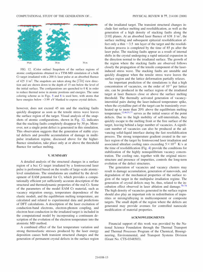
however, does not exceed 45 nm and the stacking faultsquickly disappear as soon as the tensile stress wave leavesthe surface region of the target. Visual analysis of the snap-shots of atomic configurations, shown in Fig. 12, indicatesthat the stacking faults completely disappear by 30 ps. More-over, not a single point defect is generated in this simulation.This observation suggests that the generation of stable crys-tal defects and possible accumulation of damage in multi-pulse irradiation regime, discussed above for the higher-fluence simulation, take place only at or above the thresholdfluence for surface melting.
V. SUMMARY
A detailed analysis of the structural changes in a surfaceregion of a bcc Cr target irradiated by a femtosecond laserpulse is performed based on the results of large-scale atomic-level simulations. The simulations are enabled by the devel-opment of EAM potential for Cr, which provides a compu-tationally efficient yet sufficiently accurate description of thestructural and thermodynamic properties of the real Cr. Someof the parameters of the model EAM Cr material, such asvacancy migration energy, temperature dependence of theelastic moduli, and the equilibrium melting temperature, arecalculated and related to experimental data and predictionsof DFT calculations. A description of the laser excitation ofconduction-band electrons, electron-phonon coupling, andelectron heat conduction in the irradiated target is included inthe computational model by incorporating a continuum de-scription of the evolution of the electron temperature into theatomistic MD method.
A combined effect of the fast temperature variation andstrong thermoelastic stresses produced by the laser energydeposition causes both transient structural changes and thegeneration of permanent crystal defects in the surface region
of the irradiated target. The transient structural changes in-clude fast surface melting and resolidification, as well as thegeneration of a high density of stacking faults along the�110� planes. At an absorbed laser fluence of 638 J /m2, thesurface melting and subsequent epitaxial resolidification af-fect only a thin �3.5 nm layer of the target and the resolidi-fication process is completed by the time of 85 ps after thelaser pulse. The stacking faults appear as a result of internalshifts in the crystal undergoing a rapid uniaxial expansion inthe direction normal to the irradiated surface. The growth ofthe region where the stacking faults are observed followsclosely the propagation of the tensile component of the laser-induced stress wave. The stacking faults are unstable andquickly disappear when the tensile stress wave leaves thesurface region and the lattice deformation partially relaxes.
An important prediction of the simulations is that a highconcentration of vacancies, on the order of 10−3 per latticesite, can be produced in the surface region of the irradiatedtarget at laser fluences close or above the surface meltingthreshold. The thermally activated generation of vacancy-interstitial pairs during the laser-induced temperature spike,when the crystalline part of the target can be transiently over-heated up to more than 20% above the equilibrium meltingtemperature,12,46,51,77 serves as the initial source of the pointdefects. Due to the high mobility of self-interstitials, theyquickly escape to the melting front or the free surface of thetarget, leaving behind a large number of vacancies. A signifi-cant number of vacancies can also be produced at the ad-vancing solid-liquid interface during the fast resolidificationprocess. The strong temperature gradient created in the sur-face region of the target by femtosecond laser irradiation andassociated ultrafast cooling rates exceeding 5�1012 K /s atthe time of resolidification �Fig. 4� provide the conditions forstabilization of the highly nonequilibrium vacancy concen-tration. The cooling rate, together with the original micro-structure and presence of impurities, controls the long-termevolution of the defect structures.
The generation of vacancies and vacancy clusters mayresult in damage accumulation, generation of nanovoids, anddegradation of the mechanical properties of the surface re-gion of the target in the multipulse irradiation regime. Thegeneration of crystal defects may be, thus, related to the in-cubation effect observed in laser ablation and damage.70–74
The high density of vacancies generated in the surface regionshould also play an important role in redistribution of impu-rities or mixing/alloying in multicomponent or compositetargets. The small depth of the region where the defects aregenerated may provide avenues for controlled nanoscalemodification of material properties.
ACKNOWLEDGMENTS
Financial support of this work was provided by the Na-tional Science Foundation through the Thermal Transportand Thermal Processes Program of the Chemical, Bioengi-neering, Environmental, and Transport Systems Division�Grant No. CTS-0348503�.
FIG. 12. �Color online� Snapshots of the surface regions ofatomic configurations obtained in a TTM-MD simulation of a bulkCr target irradiated with a 200 fs laser pulse at an absorbed fluence
of 425 J /m2. The snapshots are taken along the �1̄1̄0� view direc-tion and are shown down to the depth of 15 nm below the level ofthe initial surface. The configurations are quenched to 0 K in orderto reduce thermal noise in atomic positions and energies. The samecoloring scheme as in Figs. 5 and 8 is used here, with atoms thathave energies below −3.99 eV blanked to expose crystal defects.
COMPUTATIONAL STUDY OF THE GENERATION OF… PHYSICAL REVIEW B 77, 214108 �2008�
214108-13
*Author to whom correspondence should be [email protected] M. von Allmen and A. Blatter, Laser Beam Interactions with
Materials �Springer, Berlin, 1998�.2 D. Bäuerle, Laser Processing and Chemistry �Springer-Verlag,
Berlin, 2000�.3 J. Kaspar and A. Luft, Surf. Eng. 17, 379 �2001�.4 J. G. Hoekstra, S. B. Quadri, J. R. Scully, and J. M. Fitz-Gerald,
Adv. Eng. Mater. 7, 805 �2005�.5 R. Le Harzic, N. Huot, E. Audouard, C. Jonin, P. Laporte, S.
Valette, A. Fraczkiewicz, and R. Fortunier, Appl. Phys. Lett. 80,3886 �2002�.
6 V. Margetic, K. Niemax, and R. Hergenröder, Anal. Chem. 75,3435 �2003�.
7 Q. Feng, Y. N. Picard, H. Liu, S. M. Yalisove, G. Mourou, and T.M. Pollock, Scr. Mater. 53, 511 �2005�.
8 T. H. R. Crawford, J. Yamanaka, G. A. Botton, and H. K. Hau-gen, J. Appl. Phys. 103, 053104 �2008�.
9 D. S. Ivanov, B. C. Rethfeld, G. M. O’Connor, T. J. Glynn, A. N.Volkov, and L. V. Zhigilei, Appl. Phys. A: Mater. Sci. Process.�to be published�.
10 X. W. Wang, J. Phys. D 38, 1805 �2005�.11 D. S. Ivanov and L. V. Zhigilei, Phys. Rev. B 68, 064114 �2003�.12 D. S. Ivanov and L. V. Zhigilei, Phys. Rev. Lett. 91, 105701
�2003�.13 Z. Lin and L. V. Zhigilei, Phys. Rev. B 73, 184113 �2006�.14 E. Leveugle, D. S. Ivanov, and L. V. Zhigilei, Appl. Phys. A:
Mater. Sci. Process. 79, 1643 �2004�.15 L. V. Zhigilei, D. S. Ivanov, E. Leveugle, B. Sadigh, and E. M.
Bringa, Proc. SPIE 5448, 505 �2004�.16 E. Ohmura, I. Fukumoto, and I. Miyamoto, Int. J. Jpn. Soc.
Precis. Eng. 32, 248 �1998�.17 C. Schäfer, H. M. Urbassek, and L. V. Zhigilei, Phys. Rev. B 66,
115404 �2002�.18 N. N. Nedialkov, S. E. Imamova, and P. A. Atanasov, J. Phys. D
37, 638 �2004�.19 C. Cheng and X. Xu, Phys. Rev. B 72, 165415 �2005�.20 M. B. Agranat, S. I. Anisimov, S. I. Ashitkov, V. V. Zhakhovskii,
N. A. Inogamov, K. Nishihara, Yu. V. Petrov, V. E. Fortov, andV. A. Khokhlov, Appl. Surf. Sci. 253, 6276 �2007�.
21 S. I. Anisimov, B. L. Kapeliovich, and T. L. Perel’man, Sov.Phys. JETP 39, 375 �1974�.
22 L. V. Zhigilei and B. J. Garrison, in Multiscale Modelling ofMaterials, MRS Symposia Proceedings No. 538 �Materials Re-search Society, Pittsburgh, 1999�, pp. 491–496.
23 C. Schäfer, H. M. Urbassek, L. V. Zhigilei, and B. J. Garrison,Comput. Mater. Sci. 24, 421 �2002�.
24 C. Kittel, Introduction to Solid State Physics, 7th ed. �Wiley,New York, 1996�.
25 S. D. Brorson, A. Kazeroonian, J. S. Moodera, D. W. Face, T. K.Cheng, E. P. Ippen, M. S. Dresselhaus, and G. Dresselhaus,Phys. Rev. Lett. 64, 2172 �1990�.
26 Handbook of Optical Constants of Solids I, edited by D. Palik�Academic, London, 1985�; Handbook of Optical Constants ofSolids II, edited by D. Palik �Academic, London, 1991�.
27 B. J. Lee, M. I. Baskes, H. Kim, and Y. K. Cho, Phys. Rev. B 64,184102 �2001�.
28 R. Pasianot, D. Farkas, and E. J. Savino, Phys. Rev. B 43, 6952�1991�.
29 B. Zhang, Y. Ouyang, S. Liao, and Z. Jin, Physica B �Amster-
dam� 262, 218 �1999�.30 R. A. Johnson and D. J. Oh, J. Mater. Res. 4, 1195 �1989�.31 X. W. Zhou, H. N. G. Wadley, R. A. Johnson, D. J. Larson, N.
Tabat, A. Cerezo, A. K. Petford-Long, G. D. W. Smith, P. H.Clifton, R. L. Martens, and T. F. Kelly, Acta Mater. 49, 4005�2001�.
32 P. Ehrhart, P. Jung, H. Schulta, and H. Ullmaier, in Atomic De-fects in Metals, Landolt-Börnstein, New Series, Group III, Vol.25, edited by H. Ullmaier �Springer-Verlag, Berlin, 1991�.
33 D. I. Bolef and J. de Klerk, Phys. Rev. 129, 1063 �1963�.34 J. R. Ray and A. Rahman, J. Chem. Phys. 80, 4423 �1984�.35 T. Çağın, G. Dereli, M. Uludoğan, and M. Tomak, Phys. Rev. B
59, 3468 �1999�.36 M. Karimi, G. Stapay, T. Kaplan, and M. Mostoller, Modell.
Simul. Mater. Sci. Eng. 5, 337 �1997�.37 K. Yoshimoto, G. J. Papakonstantopoulos, J. F. Lutsko, and J. J.
de Pablo, Phys. Rev. B 71, 184108 �2005�.38 K. W. Katahara, M. Nimalendran, M. H. Manghnani, and E. S.
Fisher, J. Phys. F: Met. Phys. 9, 2167 �1979�.39 Smithells Metal Reference Book, 7th ed., edited by E. A. Brandes
and G. B. Brook �Butterworth-Heinemann, Oxford, 1998�.40 J.-O. Andersson, Int. J. Thermophys. 6, 411 �1985�.41 G. K. White and C. Andrikidis, Phys. Rev. B 53, 8145 �1996�.42 M. Born, J. Chem. Phys. 7, 591 �1939�.43 J. Wang, J. Li, S. Yip, S. Phillpot, and D. Wolf, Phys. Rev. B 52,
12627 �1995�.44 V. Sorkin, E. Polturak, and J. Adler, Phys. Rev. B 68, 174102
�2003�.45 Z. H. Jin, P. Gumbsch, K. Lu, and E. Ma, Phys. Rev. Lett. 87,
055703 �2001�.46 S. N. Luo, T. J. Ahrens, T. Çağin, A. Strachan, W. A. Goddard,
and D. C. Swift, Phys. Rev. B 68, 134206 �2003�.47 The use of terms “lattice” and “lattice temperature” in this paper
does not imply the preservation of the crystalline order in thesystem. By using these terms we merely follow the terminologyestablished in the literature presenting TTM calculations, whenthe term lattice temperature is commonly used to refer to thetemperature of the ionic subsystem that can be brought out ofequilibrium with the conduction-band electrons by short pulseirradiation or high-energy ion bombardment.
48 M. Forsblom and G. Grimvall, Phys. Rev. B 72, 054107 �2005�.49 X.-M. Bai and M. Li, Phys. Rev. B 77, 134109 �2008�.50 W. H. Duff and L. V. Zhigilei, J. Phys.: Conf. Ser. 59, 413
�2007�.51 D. S. Ivanov and L. V. Zhigilei, Phys. Rev. Lett. 98, 195701
�2007�.52 J. B. Cohen, R. Hinton, K. Lay, and S. Sass, Acta Metall. 10,
894 �1962�.53 V. Vitek, Philos. Mag. 18, 773 �1968�.54 V. Vitek, Philos. Mag. 21, 1275 �1970�.55 R. A. Johnson, Phys. Rev. 134, A1329 �1964�.56 G. J. Ackland and R. Thetford, Philos. Mag. A 56, 15 �1987�.57 D. Nguyen-Manh, A. P. Horsfield, and S. L. Dudarev, Phys. Rev.
B 73, 020101�R� �2006�.58 P. Olsson, J. Wallenius, C. Domain, K. Nordlund, and L. Mal-
erba, Phys. Rev. B 72, 214119 �2005�.59 P. M. Derlet, D. Nguyen-Manh, and S. L. Dudarev, Phys. Rev. B
76, 054107 �2007�.60 B. D. Wirth, G. R. Odette, D. Maroudas, and G. E. Lucas, J.
Nucl. Mater. 244, 185 �1997�.
LIN, JOHNSON, AND ZHIGILEI PHYSICAL REVIEW B 77, 214108 �2008�
214108-14
61 Yu. N. Osetsky, D. J. Bacon, A. Serra, B. N. Singh, and S. I.Golubov, J. Nucl. Mater. 276, 65 �2000�.
62 N. Soneda and T. D. de la Rubia, Philos. Mag. A 78, 995 �1998�.63 K. Arakawa, K. Ono, M. Isshiki, K. Mimura, M. Uchikoshi, and
H. Mori, Science 318, 956 �2007�.64 N. Soneda and T. Diaz de La Rubia, Philos. Mag. A 81, 331
�2001�.65 D. A. Terentyev, L. Malerba, and M. Hou, Phys. Rev. B 75,
104108 �2007�.66 R. C. Pasianot, A. M. Monti, G. Simonelli, and E. J. Savino, J.
Nucl. Mater. 276, 230 �2000�.67 F. Gao, D. J. Bacon, P. E. J. Flewitt, and T. A. Lewis, Nucl.
Instrum. Methods Phys. Res. B 180, 187 �2001�.68 V. G. Kapinos, Yu. N. Osetskii, and P. A. Platonov, J. Nucl.
Mater. 173, 229 �1990�.
69 B. D. Wirth, Science 318, 923 �2007�.70 D. Ashkenasi, M. Lorenz, R. Stoian, and A. Rosenfeld, Appl.
Surf. Sci. 150, 101 �1999�.71 P. T. Mannion, J. Magee, E. Coyne, G. M. O’Connor, and T. J.
Glynn, Appl. Surf. Sci. 233, 275 �2004�.72 S. E. Kirkwood, A. C. van Popta, Y. Y. Tsui, and R. Fedosejevs,
Appl. Phys. A: Mater. Sci. Process. 81, 729 �2005�.73 J. Krüger, D. Dufft, R. Koter, and A. Hertwig, Appl. Surf. Sci.
253, 7815 �2007�.74 G. Raciukaitis, M. Brikas, P. Gecys, and M. Gedvilas, Proc.
SPIE 7005, 7005 �2008�.75 T. Górecki, Z. Metallkd. 65, 426 �1974�.76 T. Górecki, Scr. Metall. 11, 1051 �1977�.77 A. B. Belonoshko, N. V. Skorodumova, A. Rosengren, and B.
Johansson, Phys. Rev. B 73, 012201 �2006�.
COMPUTATIONAL STUDY OF THE GENERATION OF… PHYSICAL REVIEW B 77, 214108 �2008�
214108-15