Embed Size (px)
Citation preview
Computational Optimization of the F-35 External Fuel
Tank for Store Separation∗
Eric F. Charlton† and M. Bruce Davis‡
Lockheed Martin Aeronautics Co., Fort Worth, Texas, 76101
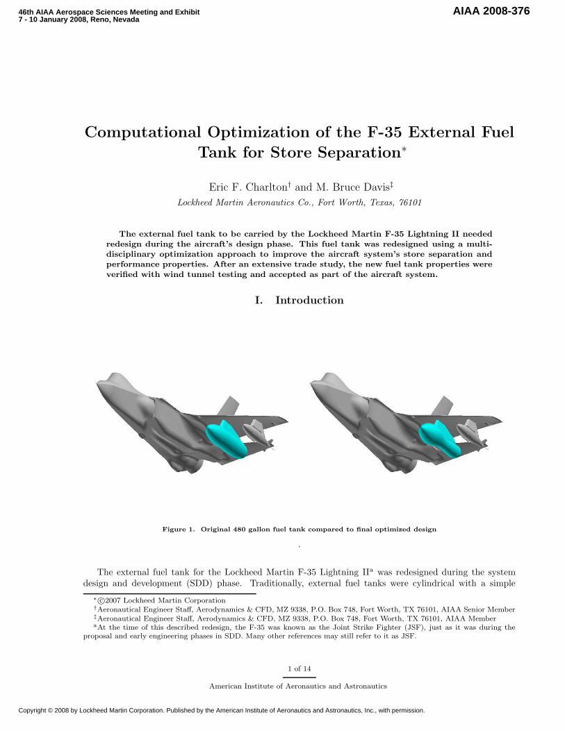
The external fuel tank to be carried by the Lockheed Martin F-35 Lightning II needed
redesign during the aircraft’s design phase. This fuel tank was redesigned using a multi-
disciplinary optimization approach to improve the aircraft system’s store separation and
performance properties. After an extensive trade study, the new fuel tank properties were
verified with wind tunnel testing and accepted as part of the aircraft system.
I. Introduction
Figure 1. Original 480 gallon fuel tank compared to final optimized design
.
The external fuel tank for the Lockheed Martin F-35 Lightning IIa was redesigned during the systemdesign and development (SDD) phase. Traditionally, external fuel tanks were cylindrical with a simple
∗ c©2007 Lockheed Martin Corporation†Aeronautical Engineer Staff, Aerodynamics & CFD, MZ 9338, P.O. Box 748, Fort Worth, TX 76101, AIAA Senior Member‡Aeronautical Engineer Staff, Aerodynamics & CFD, MZ 9338, P.O. Box 748, Fort Worth, TX 76101, AIAA MemberaAt the time of this described redesign, the F-35 was known as the Joint Strike Fighter (JSF), just as it was during the
proposal and early engineering phases in SDD. Many other references may still refer to it as JSF.
1 of 14
American Institute of Aeronautics and Astronautics
46th AIAA Aerospace Sciences Meeting and Exhibit7 - 10 January 2008, Reno, Nevada
AIAA 2008-376
Copyright © 2008 by Lockheed Martin Corporation. Published by the American Institute of Aeronautics and Astronautics, Inc., with permission.

forebody and boattail. At the start of SDD, the F-35 was expected to carry the standard U.S. Navy 480gallon drop tank, in common with the F/A-18 Hornet. The original fuel tank and the final aero-optimizedfuel tank are shown in Figure 1.
Figure 2. Store release trajectories adjacent to original baseline fuel tank
Around the time of the Preliminary Design Review in early 2003, however, at least three external storesdid not meet safe release criteria adjacent to this baseline fuel tank. Instead, certain stores would rapidly yawupon release, creating some danger of striking the aircraft or adjacent fuel tank upon their departure. Samplestore separation trajectories for large stores such as a two-thousand pound Joint Direct Attack Munition(2k JDAM) and Joint Standoff Weapon (JSOW) are shown in Figure 2.
Subsequent computational fluid dynamics (CFD) analyses were performed to evaluate the aerodynamicproperties on stores adjacent to the baseline fuel tank as well as the bottom of the aircraft, using theLockheed Martin internally developed adaptive grid code Splitflow .1–3 Examination of the surface pressuresin Figure 3 as well as the intermediate flow field indicated that it was the extreme expansion and strongshockwaves created by the transonic interference flow pattern between the stores beneath the airplane thatwas leading to the aberrant loads on the stores in carriage (and upon release).
Previous aircraft have had similar issues with store separation when carrying large stores. One well-known design modification involves changing the toe-out of the pylon mounts. Ideally, changing the toe-outchanges the aerodynamic incidence angles which loads all of the stores with a consistent side force, off-settingthe adverse loads that lead to unsafe separation. However, increasing the aerodynamic loads on all of thestores often leads to significant increases in drag, as well as potentially exposing the stores to increases inunsteady loading and fatigue over their design lifetime.
For the F-35, increasing the toe-out of the stores was examined via CFD analysis. However, severaldegrees of toe-out were required to significantly offset the adverse aerodynamic loads, and the CFD designanalysis indicated that adding too much toe-out could lead to even more unsafe store release. While clearlythe smallest possible amount would have been chosen, large changes in aerodynamic character are to beavoided on a tactical aircraft that has to operate within a very large flight envelope and would regularlyencounter off-design conditions.
By this time in SDD, the F-35 outer mold lines had already been frozen and were not expected to change.The aircraft, however, did not require a particular external fuel tank shape. Since the adverse store separationappeared to be generated by extreme aerodynamic interference, and aerodynamic properties arise from shape
2 of 14
American Institute of Aeronautics and Astronautics

Figure 3. Cp contours from CFD analysis of original fuel tank configuration shows strong expansion and shock structure
between the airplane and store load
(particularly at high speeds), alternate shapes could be considered for the fuel tank. An initial test of theconcept with a new shape—a modified version of the baseline tank—showed dramatic improvement.
Design studies were then launched using parametrically morphed new fuel tank shapes, each evaluatedfor store separation and performance characteristics with CFD. Eventually, the parameter choice, shapemorphing, and CFD evaluation for aerodynamic system performance, as well as store separation evaluation,were all combined into a design loop that was driven by an optimization program.
II. Geometric Shape Morphing
The geometry space was explored by geometrically morphing the discretized model of the original 480gallon fuel tank. Since modifying the tank shape was a relatively undesirable design change to favor, thegeometric degrees of freedom were kept relatively close to baseline; in particular, the tank length andpositioning on the aircraft were kept consistent with the original design, which had already taken intoaccount the aerodynamic loads on the wing and aircraft carrier deck strike on recovery, as well as aircraftcarrier operations, and minimizing machining and assembly complexity; constraints such as these left justradial changes in the search space.
Figure 4. Basic shape morphing method
3 of 14
American Institute of Aeronautics and Astronautics

LMAero developed in-house methods were used to morph the shapes. These methods use the US NavyDT NURBS6 library to generate intermediate models. The original discretized model is mapped to anintermediate surrogate model created from non-uniform rational B-splines (NURBS). This intermediatemodel can then be easily morphed by modifying the control points, and the resultant changes can be quicklyreflected by the discrete model. This new discrete model is then usable for further computation. The processis diagrammed in Figure 4.
Figure 5. The side view shows the reshaped pylon that still fills the area between the fuel tank and wing OML
One particular complication for this shape optimization process is that a pylon is used to mount the fueltank to the wing. The pylon needs to fit both components. For a morphing-type analysis as was used here,the pylon must either shrink if the fuel tank gets larger, or it must expand to fill the gap if the fuel tankshrinks. For this project, a custom algorithm was developed that used the computed upper outer mold linecurve of the fuel tank to stretch the existing pylon to fill the gap. For the final design, a “shoe” was addedto the fuel tank along its spine, to complete this “stretched” pylon shape and mate to the aircraft’s weaponspylon. This aspect is shown in Figure 5.
III. CFD Aerodynamic Analysis
The LMAero developed CFD analysis code Splitflow was used for the aerodynamic evaluation. Splitflow
is an adaptively-refined Cartesian-grid finite-volume CFD code that automatically builds its computationalgrid based on a user’s discrete input surface. Splitflow is an steady/unsteady Euler/RANS solver withtwo-equation k-kl turbulence model that uses a preconditioner to accurately solve incompressible flows.Splitflow can handle both quasi-steady morphing bodies, as well as dynamic flow solutions with movingbodies. Splitflow runs in parallel using MPI with an automatic domain decomposition scheme.
Splitflow is particularly well suited for complicated aerodynamics, such as store carriage and separation,since it will automatically refine the grid to areas of large surface curvature. It will also refine to any regionsspecified by the user, as well as continue to adaptively refine the grid in regions of solution gradients as theflow solution progresses. It has a long history of R&D and application in this area.7, 8 An example from thisseries of analysis showing some of the adapted grid is shown in Figure 6.
4 of 14
American Institute of Aeronautics and Astronautics
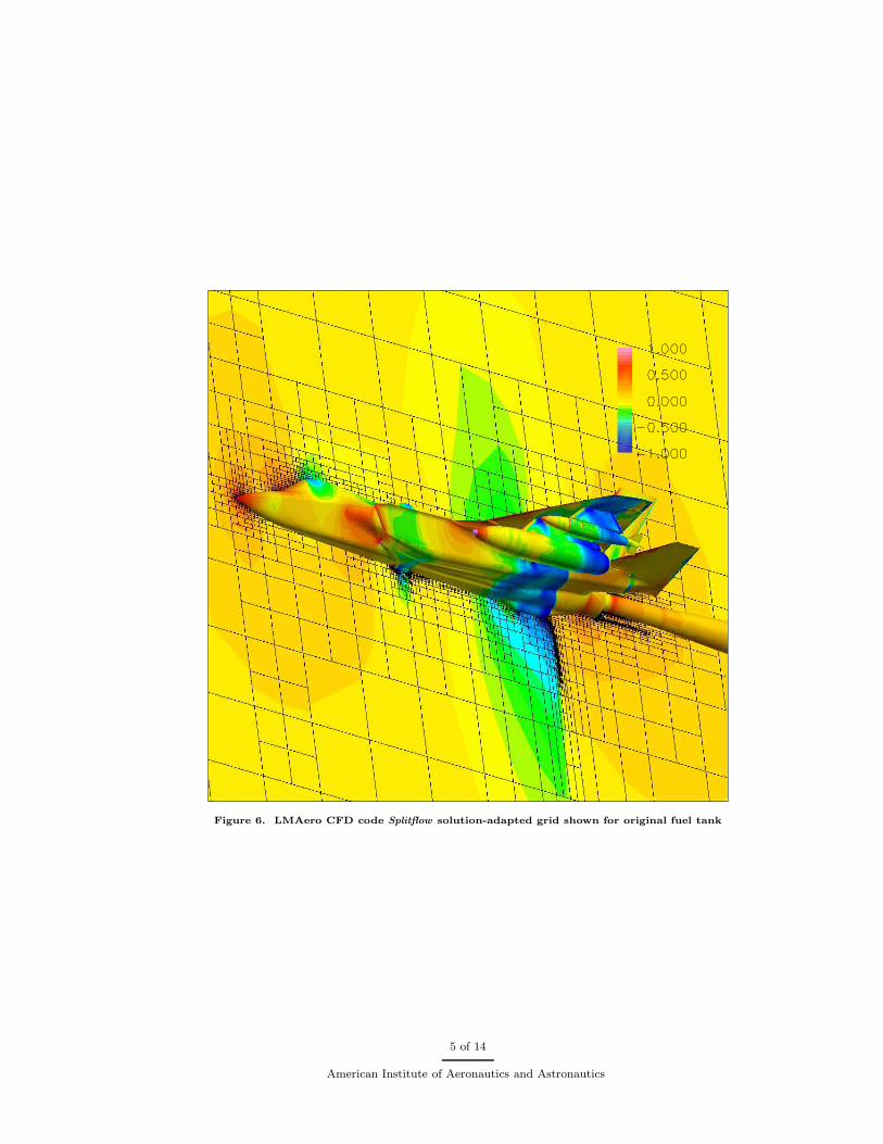
Figure 6. LMAero CFD code Splitflow solution-adapted grid shown for original fuel tank
5 of 14
American Institute of Aeronautics and Astronautics
Since Splitflow can easily regrid if the surface moves or is changed, and it can re-adapt to any resultantchanges in the flow solution structure, Splitflow proved to be exceptionally well-suited for this CFD evalu-ation. Each of the individual CFD cases that were specified by DAKOTA were restarted from a baseline,mostly-converged flow solution.
As shown in Figure 3, the flow field is very complicated, dominated by the acceleration regions andstrong terminating shockwaves between the store load and the lower surface of the aircraft. Since it wouldbe difficult to precisely locate any of these flow features for an arbitrary flight condition a priori, much lessgiven the wide range of geometries that were requested by the DAKOTA optimizer, allowing the CFD codeto adaptively refine to important flow features automatically can provide a superior solution in an analysisthat spans a relatively short period of time.
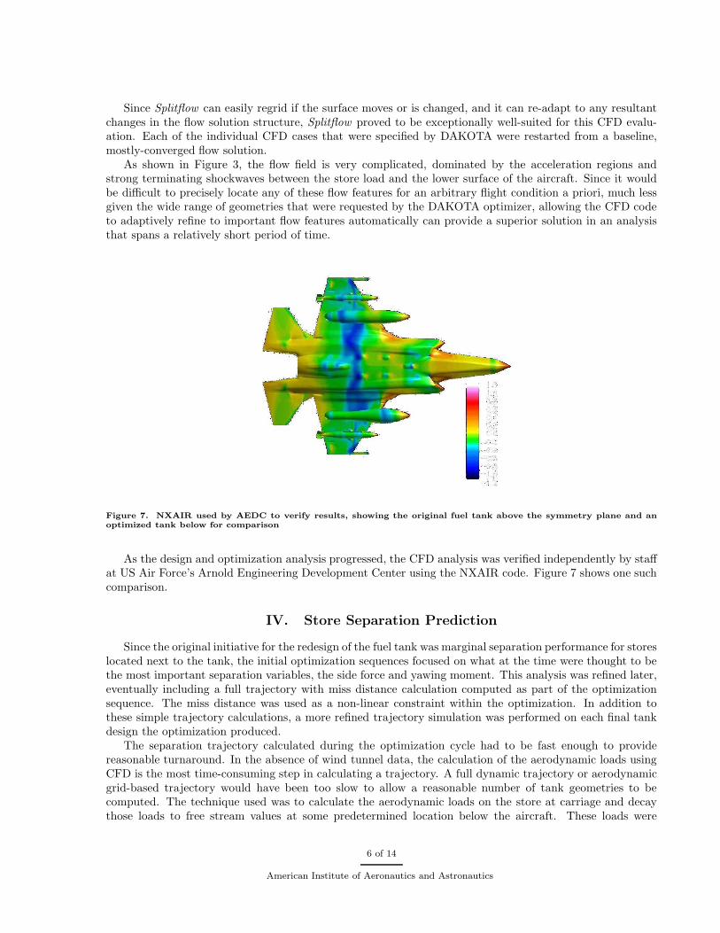
Figure 7. NXAIR used by AEDC to verify results, showing the original fuel tank above the symmetry plane and an
optimized tank below for comparison
As the design and optimization analysis progressed, the CFD analysis was verified independently by staffat US Air Force’s Arnold Engineering Development Center using the NXAIR code. Figure 7 shows one suchcomparison.
IV. Store Separation Prediction
Since the original initiative for the redesign of the fuel tank was marginal separation performance for storeslocated next to the tank, the initial optimization sequences focused on what at the time were thought to bethe most important separation variables, the side force and yawing moment. This analysis was refined later,eventually including a full trajectory with miss distance calculation computed as part of the optimizationsequence. The miss distance was used as a non-linear constraint within the optimization. In addition tothese simple trajectory calculations, a more refined trajectory simulation was performed on each final tankdesign the optimization produced.
The separation trajectory calculated during the optimization cycle had to be fast enough to providereasonable turnaround. In the absence of wind tunnel data, the calculation of the aerodynamic loads usingCFD is the most time-consuming step in calculating a trajectory. A full dynamic trajectory or aerodynamicgrid-based trajectory would have been too slow to allow a reasonable number of tank geometries to becomputed. The technique used was to calculate the aerodynamic loads on the store at carriage and decaythose loads to free stream values at some predetermined location below the aircraft. These loads were
6 of 14
American Institute of Aeronautics and Astronautics

then used in a six-degree-of-freedom (6DOF) trajectory calculation to compute the trajectory for each tankiteration. After the trajectory was calculated, a miss distance calculation was performed to find the minimumdistance between the store and the pylon and/or tank. This distance was used as the non-linear constraintin the optimization procedure.
The trajectory calculation procedure just described as part of the optimization cycle is simple but lessaccurate than more refined analysis. For this reason, each optimized tank design was analyzed for separationby a more refined trajectory calculation. The turnaround time on this refined calculation had to be on theorder of days in order to quickly evaluate whether or not the design was valid. A minimized domain CFDprocedure9 was used to rapidly calculate the aerodynamic loads at a predetermined set of locations andorientations presumed to envelope the trajectory. The minimized domain method uses a relatively smallcomputational domain surrounding the store and uses as boundary conditions the flow variables computedon a full aircraft configuration to compute the loads on the store relatively quickly. Since the solution ateach position and orientation is independant of the others, this can be done on several nodes of a parallelcomputer concurrently. These loads were then used in the 6DOF trajectory software to compute the storetrajectory. The turnaround time for this entire process was on the order of one day.
CFD Minimized Domain Wind Tunnel CTS
Figure 8. Minimized domain CFD based trajectory solution is very close to wind tunnel data
The minimized domain-based trajectory calculation was compared to the wind tunnel test data to validatethe procedure at the flight condition of interest. Figure 8 shows this comparison, and the CFD-based analysisis reasonably close to the test data. The pitching moment is underpredicted slightly while the yawing momentis slightly overpredicted. The resultant trajectory, and especially the miss distance, is very close. Figure 9shows trajectory comparisons of the store next to the baseline tank and next to the Dakota-14 tank (which isclosest to the eventually selected tank) showing the vastly improved separation performance of the redesignedtank.
V. Optimization Cycle
Several optimization cycles were employed through this redesign. Each cycle was a separate design, withits own particular optimization goals or constraints. In the early stages, raw components such as storeyaw force and moment were used as the optimization goal. Eventually, safe separation was designed for by
7 of 14
American Institute of Aeronautics and Astronautics
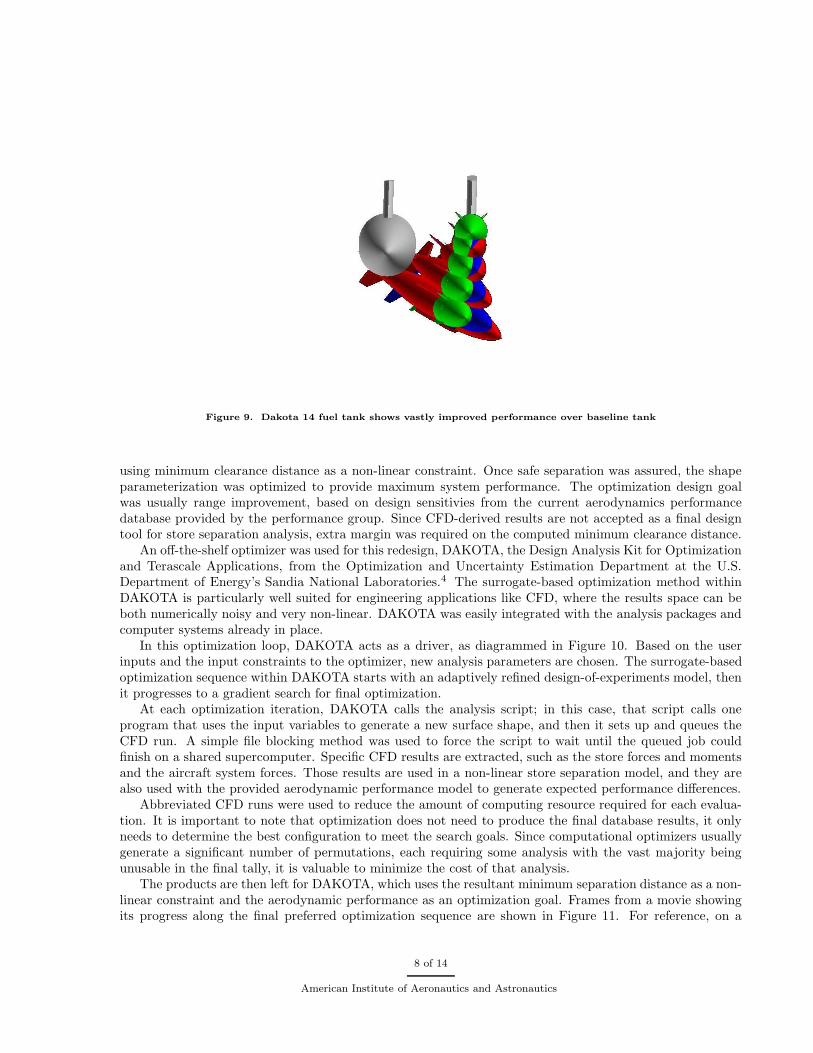
Figure 9. Dakota 14 fuel tank shows vastly improved performance over baseline tank
using minimum clearance distance as a non-linear constraint. Once safe separation was assured, the shapeparameterization was optimized to provide maximum system performance. The optimization design goalwas usually range improvement, based on design sensitivies from the current aerodynamics performancedatabase provided by the performance group. Since CFD-derived results are not accepted as a final designtool for store separation analysis, extra margin was required on the computed minimum clearance distance.
An off-the-shelf optimizer was used for this redesign, DAKOTA, the Design Analysis Kit for Optimizationand Terascale Applications, from the Optimization and Uncertainty Estimation Department at the U.S.Department of Energy’s Sandia National Laboratories.4 The surrogate-based optimization method withinDAKOTA is particularly well suited for engineering applications like CFD, where the results space can beboth numerically noisy and very non-linear. DAKOTA was easily integrated with the analysis packages andcomputer systems already in place.
In this optimization loop, DAKOTA acts as a driver, as diagrammed in Figure 10. Based on the userinputs and the input constraints to the optimizer, new analysis parameters are chosen. The surrogate-basedoptimization sequence within DAKOTA starts with an adaptively refined design-of-experiments model, thenit progresses to a gradient search for final optimization.
At each optimization iteration, DAKOTA calls the analysis script; in this case, that script calls oneprogram that uses the input variables to generate a new surface shape, and then it sets up and queues theCFD run. A simple file blocking method was used to force the script to wait until the queued job couldfinish on a shared supercomputer. Specific CFD results are extracted, such as the store forces and momentsand the aircraft system forces. Those results are used in a non-linear store separation model, and they arealso used with the provided aerodynamic performance model to generate expected performance differences.
Abbreviated CFD runs were used to reduce the amount of computing resource required for each evalua-tion. It is important to note that optimization does not need to produce the final database results, it onlyneeds to determine the best configuration to meet the search goals. Since computational optimizers usuallygenerate a significant number of permutations, each requiring some analysis with the vast majority beingunusable in the final tally, it is valuable to minimize the cost of that analysis.
The products are then left for DAKOTA, which uses the resultant minimum separation distance as a non-linear constraint and the aerodynamic performance as an optimization goal. Frames from a movie showingits progress along the final preferred optimization sequence are shown in Figure 11. For reference, on a
8 of 14
American Institute of Aeronautics and Astronautics
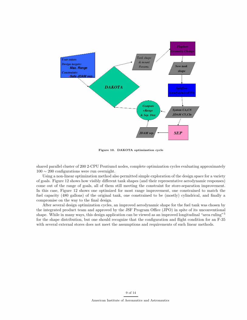
Figure 10. DAKOTA optimization cycle
shared parallel cluster of 200 2-CPU Pentium4 nodes, complete optimization cycles evaluating approximately100 ∼ 200 configurations were run overnight.
Using a non-linear optimization method also permitted simple exploration of the design space for a varietyof goals. Figure 12 shows how visibly different tank shapes (and their representative aerodynamic responses)come out of the range of goals, all of them still meeting the constraint for store-separation improvement.In this case, Figure 12 shows one optimized for most range improvement, one constrained to match thefuel capacity (480 gallons) of the original tank, one constrained to be (mostly) cylindrical, and finally acompromise on the way to the final design.
After several design optimization cycles, an improved aerodynamic shape for the fuel tank was chosen bythe integrated product team and approved by the JSF Program Office (JPO) in spite of its unconventionalshape. While in many ways, this design application can be viewed as an improved longitudinal “area ruling”5
for the shape distribution, but one should recognize that the configuration and flight condition for an F-35with several external stores does not meet the assumptions and requirements of such linear methods.
9 of 14
American Institute of Aeronautics and Astronautics
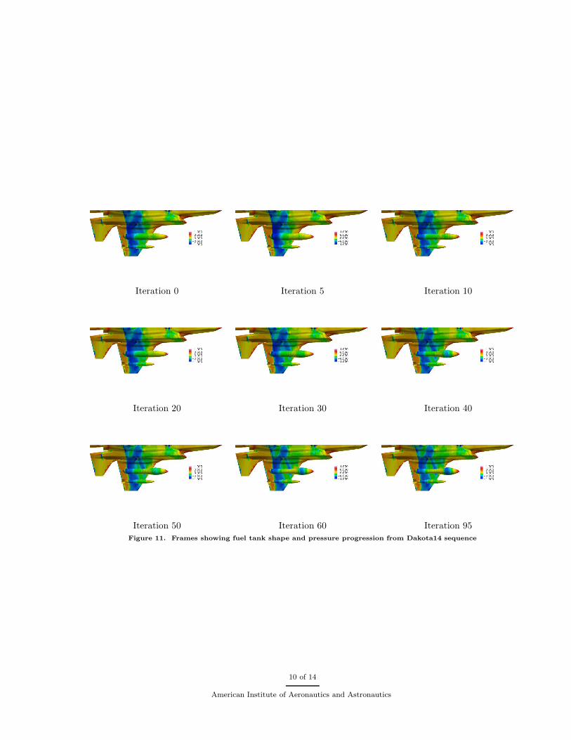
Iteration 0 Iteration 5 Iteration 10
Iteration 20 Iteration 30 Iteration 40
Iteration 50 Iteration 60 Iteration 95
Figure 11. Frames showing fuel tank shape and pressure progression from Dakota14 sequence
10 of 14
American Institute of Aeronautics and Astronautics
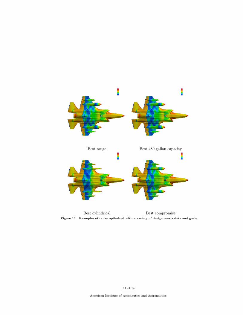
Best range Best 480 gallon capacity
Best cylindrical Best compromise
Figure 12. Examples of tanks optimized with a variety of design constraints and goals
11 of 14
American Institute of Aeronautics and Astronautics

VI. Wind Tunnel Testing
As the computational redesign completed, the new fuel tank shape was integrated into upcoming windtunnel tests for test and verification. Since familarity with CFD-derived results was low, three new tanksfrom the family of the optimized tank shapes were chosen, designated C-13, C-7, and C-4, and are shownalongside the actual wind tunnel models in Figure 13. The wind tunnel testing and modeling are describedalso in.10 C-13 most closely matched the preferred computationally generated fuel tank shape, referred toin the CFD studies as D-14.
Figure 13. Family of wind tunnel models, as well as photograph of actual tunnel models
The new aerodynamically-shaped fuel tanks were wind tunnel tested together using AEDC’s wind tun-nel facilities with captive trajectory simulation (CTS). The wind tunnel tests verified the CFD-predictedimprovements in store separation trajectory, as well as comparison of one tank to another, as shown inFigure 14.
12 of 14
American Institute of Aeronautics and Astronautics
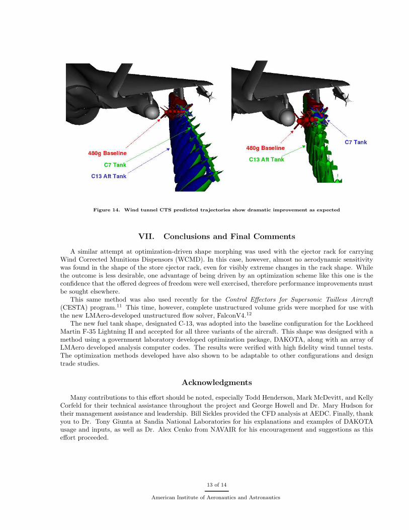
Figure 14. Wind tunnel CTS predicted trajectories show dramatic improvement as expected
VII. Conclusions and Final Comments
A similar attempt at optimization-driven shape morphing was used with the ejector rack for carryingWind Corrected Munitions Dispensors (WCMD). In this case, however, almost no aerodynamic sensitivitywas found in the shape of the store ejector rack, even for visibly extreme changes in the rack shape. Whilethe outcome is less desirable, one advantage of being driven by an optimization scheme like this one is theconfidence that the offered degrees of freedom were well exercised, therefore performance improvements mustbe sought elsewhere.
This same method was also used recently for the Control Effectors for Supersonic Tailless Aircraft
(CESTA) program.11 This time, however, complete unstructured volume grids were morphed for use withthe new LMAero-developed unstructured flow solver, FalconV4.12
The new fuel tank shape, designated C-13, was adopted into the baseline configuration for the LockheedMartin F-35 Lightning II and accepted for all three variants of the aircraft. This shape was designed with amethod using a government laboratory developed optimization package, DAKOTA, along with an array ofLMAero developed analysis computer codes. The results were verified with high fidelity wind tunnel tests.The optimization methods developed have also shown to be adaptable to other configurations and designtrade studies.
Acknowledgments
Many contributions to this effort should be noted, especially Todd Henderson, Mark McDevitt, and KellyCorfeld for their technical assistance throughout the project and George Howell and Dr. Mary Hudson fortheir management assistance and leadership. Bill Sickles provided the CFD analysis at AEDC. Finally, thankyou to Dr. Tony Giunta at Sandia National Laboratories for his explanations and examples of DAKOTAusage and inputs, as well as Dr. Alex Cenko from NAVAIR for his encouragement and suggestions as thiseffort proceeded.
13 of 14
American Institute of Aeronautics and Astronautics
References
1Karman, Jr., S. L., “SPLITFLOW: A 3D Unstructured Cartesian/Prismatic Grid CFD Code for Complex Geometries,”33rd AIAA Aerospace Sciences Meeting and Exhibit, 1995, AIAA-95-0343
2Domel, N. D. and Karman, Jr., S. L., “Splitflow: Progress in 3D CFD with Cartesian Omni-tree Grids for ComplexGeometries,” 38th AIAA Aerospace Sciences Meeting and Exhibit, 2000, AIAA-2000-1006
3Charlton, E. F. and Cunningham, Jr., A. M., “Conformal Fuel Tank Design for Gunfire with CFD,” 21st AIAA AppliedAerodynamics Conference, 2003, AIAA-2003-3677
4Eldred, M. S., et. al, DAKOTA, A Multilevel Parallel Object-Oriented Framework for Design Optimization, Parameter
Estimation, Uncertainty Quantification, and Sensitivity Analysis, Version 3.1 Users Manual, Sandia National Laboratories,2003, SAND2001-3796
5Kuethe, A. M., and Chow, C.-Y., Foundations of Aerodynamics, Bases of Aerodynamic Design, John Wiley and Sons,Inc., 1986
6DT NURBS Spline Geometry Subprogram Library Users’ Manual, Carderock Division, Naval Surface Warfare Center,United States Navy, David Taylor Model Basin, Bethesda, Maryland 20084-5000, version 2.2
7Welterlen, T. J., and Leone, C., “Application of Viscous, Cartesian CFD to Aircraft Stores Carraige and SeparationSimulation,” 14th AIAA Applied Aerodynamics Conference, 1996, AIAA-96-2453
8Welterlen, T. J., “Store Release Simulation on the F/A-18C Using Splitflow,” 37th AIAA Aerospace Sciences Meetingand Exhibit, 1999, AIAA-99-0124
9Davis, M. B., Welterlen, T. J., Corfeld, K. J., “Minimized Domain CFD for Store Separation,” 41st AIAA AerospaceSciences Meeting and Exhibit, 2003, AIAA-2003-1245
10Hudson, M. and Charlton, E., “Many Uses of CFD in JSF Store Separation,” International Aircraft-Stores Compatibility
Symposium XIV, Fort Walton Beach, FL, April 13, 200611Control Effectors for Supersonic Tailless Aircraft–Concept Development, USAF AFRL/VAAA Contract F33615-00-D-
3053 Delivery Order 0076, Program Monitor: Alyson Turri12Davis, M. B., Reed, C. L., and Yagle, P. J., “Hybrid Grid Solutions on the (CAWAPI) F-16XL Using Falcon v4,” 45th
AIAA Aerospace Sciences Meeting and Exhibit, 2007, AIAA-2007-0680
14 of 14
American Institute of Aeronautics and Astronautics