Embed Size (px)
Citation preview

Computational Materials Science 79 (2013) 908–917
Contents lists available at ScienceDirect
Computational Materials Science
journal homepage: www.elsevier .com/locate /commatsci
Finite element study of multi-modal vibration damping for thermalbarrier coating applications
0927-0256/$ - see front matter � 2013 Elsevier B.V. All rights reserved.http://dx.doi.org/10.1016/j.commatsci.2013.07.027
⇑ Corresponding author. Address: Harvard University, 29 Oxford Street,Cambridge, MA, United States. Tel./fax: +1 4044147912.
E-mail address: [email protected] (F. Casadei).
F. Casadei ⇑, K. Bertoldi, D.R. ClarkeSchool of Engineering and Applied Sciences, Harvard University, Cambridge, MA, United States
a r t i c l e i n f o
Article history:Received 3 May 2013Received in revised form 1 July 2013Accepted 18 July 2013Available online 19 August 2013
Keywords:Vibration dampingThermal barrier coatingAnelastic relaxationFinite element modeling
a b s t r a c t
A physically-based computational model is developed to predict the damping behavior of oxide thermalbarrier coating systems. The constitutive damping model is derived from the theory of point defect relax-ation in crystalline solids and implemented within a finite element framework. While oxide coatings havebeen primarily employed as thermal barriers for gas turbine blades, there is a growing interest in devel-oping multifunctional coatings combining thermal protection and damping capabilities. The direct fre-quency response method, as well as the modal strain energy method, have been implemented toevaluate the functional dependance of damping on temperature and frequency. Numerical results are val-idated through the limited experimental data available in the literature, and new results are presented toillustrate the effects of different topcoat oxides. The paper also illustrates how the developed methodol-ogy enables the damping capacity under different vibrational modes to be predicted, and to estimate thesensitivity of the design for varying geometrical parameters. Finally, the computational model is appliedto investigate the damping performance of an oxide-coated turbine blade.
� 2013 Elsevier B.V. All rights reserved.
1. Introduction
Developing vibration damping methods is critical in many tech-nologies and especially so for gas turbine engines since many oftheir rotating components have to operate under a combinationof highly exacting temperature creep-fatigue conditions and withhigh dimensional tolerances [1]. For instance, in the compressorand hot sections of the turbine, the blades have to withstand bothhigh inertial stresses and repeated buffeting as they continuouslyrotate past stationary blades being periodically shadowed.Depending on the details of the design, these buffeting frequenciesare in the 10 kHz range. Currently, damping is introduced by usingmechanical dampers included under each blade, as well as throughdamped supports [2]. Dangerous resonances are avoided by delib-erately mistuning the resonant frequencies of individual blades ona disk [3], and by controlling the spinning up of the turbine toavoid resonances.
One of the advances made in gas turbine technologies, has beenthe widespread use of thermal barrier coatings applied to thesurface of blades to provide thermal protection to the superalloycomponents. These coatings have enabled the turbine operatingtemperatures to be increased, facilitating improved energy
efficiency, while minimizing increased metal temperatures [4–7].While their primary function is as a refractory, there is also interestin developing coatings with dual functionality, combining thermalprotection and damping capabilities [8–11].
In evaluating a new damping material for use in an applica-tion such as a coating, the design engineer is faced with anumber of challenges. One is to predict the behavior of amaterial under a variety of conditions based only on a limitedamount of data. Another is to establish the behavior of a com-plex shaped component, such as an airfoil blade, that consists ofan alloy and a coating whose properties are different at differenttemperatures. As we will show in this contribution, a physically-based computational model can be used to address thesequestions.
The organization of this paper is as follows. First, we presentdata on the damping behavior of materials used in current thermalbarrier coatings and superalloy as well as some other candidateoxides. This data will be used as input for the damping computa-tions. Then, we briefly describe the point defect rearrangementmechanism which is used as a basis for the constitutive model ofdamping. The model is then implemented in a finite elementanalysis using both the direct frequency response method andthe modal strain energy method. The numerical results arecompared to the experimental data presented in Section 2, forthe purpose of validating them. Then, the damping of a simplecantilever beam under different vibrational modes is calculated.

Fig. 1. Comparison between the temperature dependent flexural damping of threeoxides in the kHz frequency range. The curves through the data represent the bestfit to the constitutive model described in Section 3.
Fig. 2. Flexural vibration damping as a function of temperature for a thermalbarrier coating system as well as data for the uncoated PWA-1484 superalloy.
F. Casadei et al. / Computational Materials Science 79 (2013) 908–917 909
Finally, the computational method is used to investigate the damp-ing capacity of a turbine blade shaped specimen.
2. Damping in thermal barrier coating systems
Thermal barrier coatings (TBCs), currently in use, typically con-sist of 7 weight% yttria-stabilized zirconia (7YSZ) deposited on asuperalloy with a thin, intermediate alloy interlayer.1 Other oxidecompositions, including Gd2Zr2O7 and Zr3Y4O12, have also beeninvestigated as alternative TBCs [12]. The superalloys of interestare primarily second-generation nickel-based alloys, such as thecommercial PWA 1484, CMSX-4 and N5 single crystal alloys [13].
The damping characteristics of all these materials have beenmeasured for flexural beam configurations by means of the fre-quency response method [14,15]. Measurements are conductedunder small displacement conditions from room temperature upto a maximum of about 1000 �C. The functional dependence ofdamping on temperature for the three oxides mentioned above isshown in Fig. 1. Although in all these materials damping is believedto originate from similar defect mechanisms [15], their dampingpeaks occur at significantly different, albeit moderate, tempera-tures, between 200 �C and 500 �C.
A second experiment is performed to compare the loss factor ofa PWA 1484 superalloy beam with and without a 142 lm thick7YSZ coating. Fig. 2 illustrates that the 7YSZ coating produces adamping peak at a temperature of about 200 �C that is absent inthe bare superalloy. This observation is similar to the one obtainedfrom internal friction measurements of single crystal zirconia in[16], and is consistent with the experimental results obtained fordense 7YSZ in Fig. 1. Moreover, consistently with results presentedin [14], Fig. 2 shows a clearly defined damping peak at tempera-tures above 900 �C that has been attributed to Ni and Al diffusionalhopping in the c0 phase [17].
While such observations can give some guidance as to otherpossible compounds may also exhibit damping, they provide littleknowledge on how such property carries over to other vibrationmodes, or what are the effects of different geometrical parametersof TBC assemblies. To address these questions, this paper proposesa physically-based computational tool which incorporates a consti-tutive model of damping based on point defect rearrangement.This mechanism is briefly described in the following section.
1 During use at high temperatures, a thin aluminum oxide layer (1–4 ln thick)forms under the 7YSZ coating.
3. Constitutive damping behavior
Point defect rearrangement under stress is the dominant mech-anism of damping in dense defective oxides such as 7YSZ [18–20].In many of these oxides, such as ThO2 doped with CaO or ZrO2
doped with Y2O3, oxygen vacancies are created to chargecompensate for the aliovalent dopant or stabilizer ion. The defectis typically a dipole consisting of an oxygen vacancy and the dop-ant ion, and it acts as both an electrostatic and an elastic dipole[21]. When the material is subject to an alternating stress at fre-quency x, the individual point-defect dipoles can switch fromone crystallographic orientation to another producing an aniso-tropic local distortion of the crystal lattice [22]. Mechanical damp-ing resulting from this dipole switching mechanism was firstanalyzed by Wachtman [23] and the interested reader is referredto his and related analyses [22,24].
Briefly, the local distortion of a lattice containing point defectsis described by a second-rank tensor k characterizing the strainof the crystal with a unit concentration (mole fraction) of dipolardefects [22]. The dipole tensor can be expressed in terms of itsprincipal values ki (i = 1,2,3) and a number nt of independent ori-entations that depend on the defect’s symmetry. The overall strainfield is therefore given by the sum of two contributions:
e ¼ eel þ ean ¼ eel þXnt
p¼1
kpCp ð1Þ
where eel is the elastic strain without defects, and ean ¼Pnt
p¼1kpCp isan anelastic strain. In Eq. (1) kp denotes the dipole tensor for one ofthe nt possible equivalent orientations of the defect, and Cp = Np/Nlis the mole fraction of defects in orientation p, where Np and Nlrespectively denote the number of defects in orientation p, andthe number of molecules per unit volume. If nt > 1, defects charac-terized by different k tensors interact differently with an appliedstress field r such that one is energetically favored over the others.This leads to a splitting of free-energy levels in which the probabil-ity of dipoles having different orientations is given by Boltzmannstatistics [22,25]. The equilibrium values of Cp for the concentra-tions at any given stress and temperature (T) are therefore given by:
Cp ¼C0v0
ntkBTkp �
1nt
Xq
kq
" #r ð2Þ
where C0 is the total molar concentration of defects (constant), v0 isthe molecular volume, and kB is the Boltzmann constant. To simplifythe calculation here we consider only a homogeneous uniaxial stateof stress (r11), the corresponding strain component (e11), as well as

910 F. Casadei et al. / Computational Materials Science 79 (2013) 908–917
k tensor components k11. For the sake of clarity the subscript 11 willbe omitted. Based on this assumption, the relaxation strength d⁄ canbe expressed as [26]:
d� ¼ ean
r¼ C0v0
ntkBT
Xp
ðkpÞ2 �1nt
Xp
kp
!224
35 ð3Þ
The kinetics of defect rearrangement to a lower energy configura-tion is, in general, a time dependent process characterized by arelaxation time s. The choice of using a single relaxation time isbased on the experimental observations [23,26] that damping insimple oxides can occur by either cation interstitials (in rutile) oroxygen vacancies (in thoria), and give rise to a single damping peak.The presence of a relaxation time allows for the mechanical energydissipated per unit cycle DU to be expressed through the followingDebye function:
DU ¼ d�xs
1þ ðxsÞ2�r2 ð4Þ
in which �r is the average applied stress. The defect relaxation is as-sumed to be a thermally activated process [23] described by the fol-lowing Arrhenius equation:
s ¼ s0 expDEkBT
� �ð5Þ
where DE is the activation energy, and the pre-exponential factor s0
is a characteristic relaxation time related to the atomic jump ratesinherent to specific defect mechanisms.
Substituting Eq. (5) into Eq. (4) yields
DU ¼ d�sech ln xs0 þDEkBT
� ��r2 ð6Þ
which compared to the total vibrational energy U ¼ �r2=2Y allowsexpressing the internal friction or damping, Q�1 as:
Q�1 ¼ DU2pU
¼ YAkBT
sech ln xs0 þDEkBT
� �ð7Þ
Here, Y denotes the Young’s modulus, and A is a material parameterwhich is a function of the defects’ concentration and orientation. Eq.(7) provides a direct constitutive relationship between macroscopicdamping characteristics and atomic level mechanism. In the presentwork, this formulation is used to characterize the dissipation mech-anism occurring in both the metallic superalloy and the oxide layerscharacterizing typical TBC systems.
4. Finite element analysis
Here, the constitutive damping behavior presented in the previ-ous section is implemented within a linear FE framework. For thistask, we adopt a phenomenological damping model based on thecorrespondence principle of linear viscoelasticity [27,28] wherebythe inherent material dissipation is described in terms of a com-plex Young’s modulus (Y⁄ = Y0 + iY00 where i ¼
ffiffiffiffiffiffiffi�1p
is the imaginaryunit) with the ratio of imaginary to real part being the material lossfactor Q�1 = Y00/Y0. The choice of adopting a phenomenologicalmodel, compared, for example, to developing a statistical-mechan-ics based material law, is motivated by the need to accuratelyestimate the damping properties of complex systems with a mod-est computational effort. This is particularly relevant for the preli-minary design of turbine blades in which several simulations aretypically conducted to estimate the effects of a number of criticaldesign parameters [29]. This section briefly describes both thedirect frequency response method and the modal strain energymethod that have been implemented as part of a in-house devel-oped finite element (FE) code to predict the damping behavior of
complex TBC systems based on experimentally-informed materialproperties.
4.1. Direct frequency response method
The FE analysis of TBC systems with distributed dissipationmechanisms can be conveniently conducted in the frequencydomain using the direct frequency response method [30]. If thestructure undergoes harmonic motion at frequency x, the general-ized forces f 2 Rn�1 and displacements u 2 Cn�1 are relatedthrough the dynamic stiffness matrix of the structure as
K1 þ iK2ðx; TÞ �x2M� �
u ¼ f ð8Þ
where M 2 Rn�n and K1 2 Rn�n are the global mass and stiffnessmatrices assembled using standard FE procedures [31], n denotesthe global number of degrees of freedom. In the present notation,lower case bold letters denote vectors, while upper case bold lettersare used for matrices. In Eq. (8) K2ðx; TÞ 2 Rn�n is a hystereticdamping matrix which depends on the material loss factor (Q�1 inEq. (7)) evaluated at frequency x and temperature T. The hystereticdamping matrix of a system comprised of M different materials,each characterized by a loss factor Q�1
j ðj ¼ 1;2; . . . ;MÞ, is given by
K2ðx; TÞ ¼XM
j¼1
Q�1j ðx; TÞK
ðjÞ1 ð9Þ
in which
KðjÞ1 ¼XNðjÞe
e¼1
Ke1 ð10Þ
is the portion of the global stiffness matrix assembled consideringonly the elemental contributions (Ke
1) of the NðjÞe finite elementsassociated with the jth material property (see [31] for details).
The frequency response of the system is computed by solving Eq.(8) for the unknown nodal displacements u(x,T) within a frequencyrange of interest typically dictated by the spectral content of theexternally applied loads. The vibration attenuation properties ofthe entire structure are then estimated in terms of a mechanical lossfactor, or inverse quality (or gain) factor Q�1
TBC defined as:
Q�1TBC ¼
Dffr
ð11Þ
where Df is the half power bandwidth (�3 dB) of the response at aresonance frequency fr [32].
The major drawback of this approach is related to the need forassembling and factorizing a complex system of equations at eachfrequency step within the range of interest. For practical designpurposes, the computational cost of direct frequency analysesmay not be cost-effective especially when conducting several para-metric analysis or optimization procedures.
4.2. Modal strain energy method
In order to reduce the computational costs associated with thedirect frequency analysis, this research considers an alternativeapproach known as the modal strain energy method [30]. This ap-proach avoids the direct solution of Eq. (8) by assuming that thedamping coefficient of a structural mode is proportional to the lossfactor of each material multiplied by the corresponding modalstrain energy ratio (SER) [30]. If the structure is comprised of M dif-ferent materials, the SER in the jth material layer is defined as
SERj ¼ U j=UTOT ðj ¼ 1;2; . . . ;MÞ ð12Þ
where U j is the fraction of strain energy stored in the jth material,and

Table 1Anelastic relaxation parameters of the considered materials.
DE (eV) s0 (s) A (–)
7YSZ 0.96 9.14 � 10�14 6.51 � 10�14
Gd2Zr2O7 0.85 1.23 � 10�14 4.51 � 10�14
Y4Zr3O12 1.01 8.21 � 10�15 6.00 � 10�14
PWA-1484 2.26 9.99 � 10�14 1.09 � 10�14
F. Casadei et al. / Computational Materials Science 79 (2013) 908–917 911
UTOT ¼XM
j¼1
U j ð13Þ
is the total strain energy associated with an undamped vibrationalmode of the system. Note that the rth undamped modal shape /r isobtained as the solution of the following real eigenvalue problem
K1 �x2r M
� �/r ¼ 0 ð14Þ
from which the components of the strain energy in Eq. (12) are gi-ven by
UrTOT ¼
12
/Tr K1/r and Ur
j ¼12
/Tr KðjÞ1 /r ð15Þ
where KðjÞ1 is defined in Eq. (10). Finally, the material loss factorassociated with the rth mode of the structure is obtained as
1=Qð Þr ¼XM
j¼1
Urj
UrTOT� Q�1
j ¼XM
j¼1
SERj � Q�1j ð16Þ
This method is known to provide accurate predictions only forsmall values of damping, i.e. when (1/Q)r� 1.5 [30]. Since for typ-ical TBCs values of Q�1 range between 10�3 and 10�2 the modalstrain energy method can be sufficiently accurate to give useful,though not necessarily exact, damping predictions.
5. Application to a coated beam system
5.1. Geometry and material properties
As an illustration, the numerical procedures presented in Sec-tion 4 are applied to predict the damping properties of a two-layercantilever beam. The configuration, schematically shown in Fig. 3,corresponds to the one used in [14] to experimentally investigatethe damping properties of a 7YSZ coated superalloy, and thereforeallows to validate the FE predictions. The beam is L = 16.9 mm long,and is characterized by a rectangular cross section (W = 5.03 mmwide) comprised of a 0.38 mm thick PWA layer, and a 0.142 mmthick topcoat. In order to predict the effects of different topcoatmaterials on the damping properties of the TBC, analyses are con-ducted using the three oxides previously investigated (i.e. 7YSZ,Gd2Zr2O7, and Y4Zr3O12). The beam is rigidly clamped at its leftend (cantilever) and is subjected to a concentrated point loadF(x) at the tip (Fig. 3). The geometry is discretized with a meshcomprising of 1920 linear (8-node) hexahedral elements, whoseaccuracy has been ascertained through a refinement study.
The activation energy (DE), relaxation time s0, and relaxationstrength (A) of the considered materials are summarized in Table 1.The constitutive damping parameters of the oxides are determinedby fitting the experimental data presented in Fig. 1 throughthe functional dependance on frequency and temperature givenby Eq. (7). The curves through the data in Fig. 1 represent the bestfit to the adopted functional model. In order to extract the material
Fig. 3. Schematic of the two-material cantilever beam used in experiments.
parameters for the PWA superalloy, the experimental datapresented in [14] have been used. Additional data used in this workbut not shown include the Young’s modulus as a functionof temperature for the superalloy and the 7YSZ coating[14,15]. The density of the PWA is assumed constant andequal to qPWA ¼ 8700 kg=m3, while an average density ofqTOP ¼ 4930 kg=m3 is used for the oxide topcoats.
5.2. Numerical results
The vibration damping of the system is evaluated using both themodal strain energy method, and the direct frequency responsemethod with frequency response functions evaluated in terms ofthe applied load F(x) and the tip displacement utip (see Fig. 3).
5.2.1. 7YSZ coated beamFirst the 7YSZ topcoat is considered and the computed results
are compared with the experimental data provided in [14]. In orderto investigate the functional dependance of damping on tempera-ture, frequency response functions are computed for increasingtemperatures from 0 to 900 �C (see Fig. 4). Interestingly, Fig. 4 illus-trates how the FE model simultaneously captures the shift of theresonance peak induced by the Young’s modulus reduction at high-er temperatures, and the functional dependence of attenuation ontemperature proper of the thermally activated relaxation mecha-nism considered herein.
The first four eigen modes of the beam, presented in Fig. 5, arealso evaluated to estimate the modal damping using the strainenergy method.
The evolution of the loss factor versus temperature is shownin Fig. 6 where numerical predictions are obtained both with thedirect frequency response method, and the modal strain energymethod. Remarkably, the results capture the damping peak tem-perature of about 200 �C induced by the 7YSZ phase, and areconsistent with the general trend exhibited by the experimentaldata (available up to 900 �C). Some discrepancies in the amountof damping predicted by the FE model are observed especially at
Fig. 4. Variation of the TBC’s frequency response as a function of temperature. Theshift of the resonance peak is induced by the reduction of the Young’s modulus withincreasing temperatures.

Fig. 5. First four normal modes of the undamped beam (T = 0 �C).
Fig. 6. Comparison between the numerical and experimental loss factor variationsof the 7YSZ coated PWA superalloy beam.
Fig. 7. Comparison between the loss factor variations of three TBCs featuring thesame PWA-1484 superalloy and different topcoat oxides.
Fig. 8. Mechanical damping associated with different vibrational modes for the7YSZ coated beam shown in Fig. 3.
912 F. Casadei et al. / Computational Materials Science 79 (2013) 908–917
intermediate temperatures. This can be attributed to a tempera-ture dependent background [33] generally not captured by theadopted model. Also consider that the contribution of the bondcoat to the overall material loss of the TBC system has not beenincluded due to insufficient experimental data available to cali-brate the corresponding damping model. Fig. 6 also shows theexcellent agreement between results computed with the directfrequency method and the strain energy approach. While themaximum discrepancy between the two sets of data is below0.5% the modal strain energy method is found about 5 times fas-ter than the direct frequency approach. For this reason the latterwill be adopted in the following section to conduct sensitivityanalyses for varying geometric parameters of the TBC.
5.2.2. Effect of different oxide coatingsA comparison between the damping of three TBCs featuring
different coating oxides is shown in Fig. 7. Interestingly, thedamping peak of each TBC occurs at the same peak temperatureof the corresponding oxide phase, and it is in excellent agree-ment with the experimental data shown for the same oxides

Fig. 9. Vibration damping associated to the first four eigenmodes of the TBC for different values of the 7YSZ layer thickness ðtYSZÞ, and for b = 1.
Fig. 10. Variation of the loss peak Q�1MaxðaÞ associated to different vibration modes as
a function of the thickness parameter a.
F. Casadei et al. / Computational Materials Science 79 (2013) 908–917 913
in Fig. 1. Whereas the peak temperature of the TBC is only dic-tated by the activation energy and relaxation time of its oxidelayer, the maximum damping capacity of the system is alsoinfluenced by design features such as the thickness and widthof each layer. The effects of such parameter on the damping per-formance of the TBC will be discussed in Section 6.
5.2.3. Damping of different vibration modesNext, we investigate how the damping properties observed for
flexural motion carry over to different vibration modes. Knowledgeof the vibration damping of individual modes is critical for the de-sign of turbine blades in which complex excitation mechanisms of-ten trigger a broadband multimodal response. Without any loss ofgenerality, analyses are conducted considering the TBC shown inFig. 3 with a 7YSZ topcoat. Fig. 8 illustrates the main dampingpeaks characterizing the first four eigenmodes of the beam(Fig. 5). Interestingly, results show a significant increase of thepeak temperature associated to higher vibration modes. This phe-nomenon is consistent with the thermally-activated nature of therelaxation mechanism in which frequency dictates the tempera-ture range of maximum material loss. The maximum dampingcapacity of each mode, instead, depends on the relaxation strengthof the constituent materials and the strain energy density stored ineach layer. For instance, Fig. 8 shows that in-plane bending vibra-tions, mostly dominated by the fourth eigenmode, feature a mod-est amount of damping at intermediate temperatures compared tothe bending or torsional motion of the beam (modes 1–3). The var-iation of such properties for different design configurations isinvestigated in the following section.
6. Effects of design parameters on the TBC damping capacity
This section investigates the effects of relevant design parame-ters on the damping capacity of the first four vibration modes ofthe TBC. Emphasis is given to the intermediate temperature range
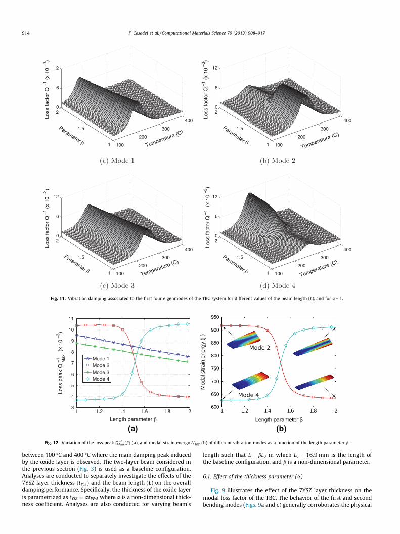
Fig. 11. Vibration damping associated to the first four eigenmodes of the TBC system for different values of the beam length (L), and for a = 1.
(a) (b)Fig. 12. Variation of the loss peak Q�1
MaxðbÞ (a), and modal strain energy UrTOT (b) of different vibration modes as a function of the length parameter b.
914 F. Casadei et al. / Computational Materials Science 79 (2013) 908–917
between 100 �C and 400 �C where the main damping peak inducedby the oxide layer is observed. The two-layer beam considered inthe previous section (Fig. 3) is used as a baseline configuration.Analyses are conducted to separately investigate the effects of the7YSZ layer thickness ðtYSZÞ and the beam length (L) on the overalldamping performance. Specifically, the thickness of the oxide layeris parametrized as tYSZ ¼ atPWA where a is a non-dimensional thick-ness coefficient. Analyses are also conducted for varying beam’s
length such that L ¼ bL0 in which L0 ¼ 16:9 mm is the length ofthe baseline configuration, and b is a non-dimensional parameter.
6.1. Effect of the thickness parameter (a)
Fig. 9 illustrates the effect of the 7YSZ layer thickness on themodal loss factor of the TBC. The behavior of the first and secondbending modes (Figs. 9a and c) generally corroborates the physical

Fig. 13. Finite element discretization of a model coated turbine blade. Fig. 15. Distribution of the strain energy (normalized units) associated to the firstbending mode of the blade.
Table 2Modal damping properties of the blade coated with different oxides.
Mode 1 Mode 2 Mode 3
Q�1max ð—Þ Tp (�C) Q�1
max ð—Þ Tp (�C) Q�1max ð—Þ Tp (�C)
7YSZ 3.60 209.2 3.59 209.2 3.54 209.2Y4Zr3O12 2.90 330.1 2.89 330.1 2.84 330.1Gd2Zr2O7 3.25 429.3 3.23 429.3 3.19 429.3
F. Casadei et al. / Computational Materials Science 79 (2013) 908–917 915
intuition underlying the modal strain energy method according towhich the damping peak increases as the thickness of the oxidelayer is increased. The same results also show a moderate shift ofthe damping peak towards higher temperatures due to the mono-tonic increase of the corresponding natural frequencies ofvibration.
A rather different behavior characterizes the trend of the firsttorsional and in-plane bending modes (Figs. 9b and d). Forintermediate values of the thickness parameter, in fact, Fig. 9b re-veals a counter-intuitive effect whereby the damping peak of thesecond mode does not increase monotonically with the thicknessof the oxide topcoat. Also, Fig. 9d shows a rapid increase of the lossfactor associated to the fourth mode occurring at values ofa ’ 1.25.
These considerations are also illustrated in Fig. 10 which showsthe variation of the damping peak Q�1
MaxðaÞ ¼ maxT Q�1ðT;aÞ as afunction of the considered thickness parameter a. These resultsindicate that for a [ 1.0 the first three modes feature roughlythe same damping capacity which increases monotonically as afunction of the topcoat thickness. The loss factor of the second (tor-sional) mode reaches a maximum at a ’ 1.15 after which thedamping of the third (in-plane bending) mode becomes more rel-evant. The existence of stationary points (i.e. maxima and minima)in the functional dependence of damping occurring for specificcombinations of the design parameters suggests the possibility ofoptimizing the performance of the TBC over a broad frequencyrange.
Fig. 14. Comparison between the loss factor variations of the first bending mode ofthe blade shown in Fig. 13 coated with the oxides shown in Fig. 1.
6.2. Effect of the length parameter (b)
The effect of the TBC length on the mechanical loss of the sys-tem is investigated by varying the length parameter (b). Resultspresented in Fig. 11a and c show that the damping of the firstand second bending modes monotonically decreases of about 1%as the TBC length is varied from once to twice its original length.As b increases, the results in Fig. 11a and c also indicate that thedamping peak of the bending modes tend to occur at lower tem-peratures due to the lowering of the corresponding natural fre-quencies. Figs. 11b and d reveal a sudden change of the TBC lossfactor associated to the second and fourth modes occurring at acritical value of bcr ’ 1.55. This behavior is also shown in Fig. 12ashowing a direct comparison between the damping peakQ�1
MaxðbÞ ¼maxT Q�1ðT; bÞ of the first four modes. Analysis of themode shapes of the structure, in fact, reveals that the deformation
Fig. 16. Frequency response function of the blade coated with a 125 lm thick layerof 7YSZ for increasing temperatures.

916 F. Casadei et al. / Computational Materials Science 79 (2013) 908–917
patterns of the second and fourth eigenmodes tend to swap as thelength parameter is increased above bcr. As shown in Fig. 12b, thiscorresponds to a redistribution of the strain energy of the twomodes which leads to a switch of the corresponding modal damp-ing characteristics.
Although the analysis presented herein focuses on a rather sim-ple geometrical configuration, the obtained results reveal complexor even counter-intuitive trends which must be considered in thedesign and optimization of oxide layers for multifunctional TBCs.
7. Analysis of a coated turbine blade
In this section, the computational model is used to investigatethe damping performance that a TBC can provide to a turbineblade-shaped specimen.
7.1. Finite element model
A prototypical blade, shown in Fig. 13, is discretized using theABAQUS FEA package while the actual FE computations are con-ducted using an in-house developed code. The blade, representinga sector of the turbine rotor, is modeled as a PWA 1484 superalloycore that is protected by a 125 lm thick thermal barrier coating.Analyses are conducted using the three oxides previously investi-gated (i.e. 7YSZ, Gd2Zr2O7, and Y4Zr3O12) whose damping materialproperties are summarized in Table 1. The Young’s modulus anddensity of the superalloy are reduced by a factor of five to accountfor the presence of cooling passages and vanes not explicitly incor-porated in the model.
The FE mesh of the blade comprises 29,624 4-node linear tetra-hedral elements (Fig. 13). The functional dependance of dampingon temperature for the three oxides is computed using the modalstrain energy method imposing fully-clamped boundary conditionsat the base of the blade. The damping properties of the system arealso verified through direct frequency response functions obtainedby imposing a random excitation to the base of the blade (Fig. 13)as typically done in vibration damping experiments [34]. Also inthis case, the maximum discrepancy between the damping esti-mated with the two methods is below 0.5%.
7.2. Numerical results
A comparison between the damping variations associated withthe first bending mode of the coated blade is shown in Fig. 14. Theresults clearly indicate that the oxide layer generates a significantdamping peak at intermediate temperatures, ranging from 200 �Cto 400 �C depending on the relaxation parameters of the specificoxide being considered, and reproduce the temperature depen-dence measured in the flexural beam. Fig. 14 however shows thatthe magnitude of the damping peak is significantly lower thanwhat observed for the cantilever beam case. This can be under-stood directly from the modal strain energy method since the rel-ative volume of the coat and superalloy is reduced on the blade.Fig. 15 shows that, contrary to many samples used for simple tests[14,15,35,36], the region of high strain energy density, and hence,damping are mostly localized in the blade.
A summary of the damping performance associated with thefirst three vibration modes for different oxides are reported in Ta-ble 2. Interestingly, the numerical results indicate that the maxi-mum loss factor Q�1
max, and the peak temperature Tp are almostinsensitive to the specific mode of vibration of the blade. AlthoughTable 2 only shows data associated with the first three modes, weobserve similar trends also for higher order vibration mechanisms(not shown for clarity), thus providing robust damping character-istics over a broad range of frequencies.
The direct frequency response of the system is also computed toillustrate the effect of damping on the blade’s steady-state re-sponse at various temperatures. Analysis are presented for a bladecoated with a 7YSZ oxide layer, but analogous results are also ob-served for the other oxides considered in this study. Fig. 16 illus-trates the frequency response function between the imposedbase motion ub and the blade’s tip displacement utip (see Fig. 13).The response function computed at T = 0 �C is used as a referenceto estimate the attenuation provided to the system by the pointdefect relaxation mechanism in the oxide layer. Remarkably, theresults indicate that at the peak temperature of about 200 �C, theTBC reduces by about 12 dB the amplitude of all the resonancemodes up to 10 kHz.
8. Conclusions
A finite element approach is used to predict the vibrationaldamping in a multi-layer TBC system due to point defect relaxationinduced by the oxide topcoat. The proposed framework is based ona description of damping as the result of anelastic relaxation due topoint defect rearrangement in highly defective oxides. The func-tional dependence of mechanical loss on temperature and vibra-tion frequency is conveniently implemented in a FE frameworkwhich allows estimation of the damping properties of complexthree-dimensional shaped TBCs. Numerical analyses are conductedusing both the direct frequency response method and, more conve-niently, the modal strain energy method which is found to providenearly identical results at a fraction of the computational cost.
Comparison with experimental data shows that the proposedframework correctly captures the damping variation of a multi-layer system based on experimentally-informed material proper-ties derived for each of the constituent materials. The approach isalso used to estimate how the damping properties, typically ob-tained for flexural motion only, carry over to other vibrationmodes. Finally, parametric analyses illustrate how the proposedapproach can estimate the effects of several design parameterson the damping performance of a TBC system. The obtained resultshighlight a complex functional dependence of damping on the geo-metrical parameters of the system, which must be considered forthe design of oxide layers for multifunctional TBCs.
Acknowledgements
The authors would like to acknowledge support of this workthrough an AF-SBIR Grant from DVTI.
References
[1] B.L. Koff, B.L. Koff, Journal of Propulsion and Power 20 (4) (2004) 577–595.[2] J.H. Griffin, International Journal of Turbo and Jet Engines 7 (3–4) (1990) 297–
308.[3] C. Yu, J. Wang, Q. Li, Journal of Vibration and Control 17 (8) (2011) 1149–1157.[4] A. Evans, D. Clarke, C. Levi, Journal of the European Ceramic Society 28 (7)
(2008) 1405–1419.[5] D. Clarke, C. Levi, Annual Review of Materials Research 33 (1) (2003) 383–417.[6] R.V. Hillery, et al., Coatings for High-Temperature Structural Materials: Trends
and Opportunities, National Materials Advisory Board Report, NationalAcademy Press, Washington, DC.
[7] U. Schulz, C. Leyens, K. Fritscher, M. Peters, B. Saruhan-Brings, O. Lavigne, J.Dorvaux, M. Poulain, R. Mévrel, M. Caliez, Aerospace Science and Technology 7(1) (2003) 73–80.
[8] K. Cross, W. Lull, R. Newman, a.R. Cavanagh, Journal of Aircraft 10 (11) (1973)689–691.
[9] C. Chia, K. Khor, Y. Gu, F. Boey, Thin Solid Films 405 (1) (2002) 146–152.[10] F. Soechting, Journal of Thermal Spray Technology 8 (4) (1999) 505–511.[11] L. Yu, Y. Ma, C. Zhou, H. Xu, International Journal of Solids and Structures 42
(11) (2005) 3045–3058.[12] D.R. Clarke, S.R. Phillpot, Materials Today 8 (6) (2005) 22–29.

F. Casadei et al. / Computational Materials Science 79 (2013) 908–917 917
[13] R.C. Reed, The Superalloys: Fundamentals and Applications, CambridgeUniversity Press, 2006.
[14] G. Gregori, L. Lı̀, J. Nychka, D. Clarke, Materials Science and Engineering: A 466(1) (2007) 256–264.
[15] A. Limarga, T. Duong, G. Gregori, D. Clarke, Surface and Coatings Technology202 (4) (2007) 693–697.
[16] M. Weller, R. Herzog, M. Kilo, G. Borchardt, S. Weber, S. Scherrer, Solid StateIonics 175 (1) (2004) 409–413.
[17] W. Hemmann, T.V. Ort, H. Sockel, Journal de Physique IV 6 (8) (1996) 223–226.[18] J. Wachtman Jr, L. Doyle, Physical Review 135 (1A) (1964) A276.[19] A. Nowick, Advances in Physics 16 (61) (1967) 1–47.[20] R. Lakes, J. Quackenbush, Philosophical Magazine Letters 74 (4) (1996) 227–232.[21] B. Berry, Acta Metallurgica 10 (4) (1962) 271–280.[22] A.S. Nowick, B.S. Berry, Anelastic Relaxation in Crystalline Solids, vol. 1,
Academic Press, 1972.[23] J. Wachtman Jr, Physical Review 131 (2) (1963) 517.[24] A. Nowick, W. Heller, Advances in Physics 14 (54) (1965) 101–166.[25] M. Callens-Raadschelders, R. De Batist, R. Gevers, Journal of Materials Science
12 (2) (1977) 251–263.[26] R. Carnahan, J. Brittain, Journal of Applied Physics 34 (10) (1963) 3095–3104.[27] D.R. Bland, The Theory of Linear Viscoelasticity, vol. 10, Pergamon Press, New
York, 1960.
[28] R. Christensen, Theory of Viscoelasticity: An Introduction, Academic press,1982.
[29] A. Shanian, A. Milani, N. Vermaak, K. Bertoldi, T. Scarinci, M. Gerendas, Journalof Applied Mechanics 79 (2012) 061019.
[30] C.D. Johnson, D.A. Kienholz, AIAA Journal 20 (9) (1982) 1284–1290.[31] T. Hughes, The Finite Element Method: Linear Static and Dynamic Finite
Element Analysis, Dover, Publications, 2000.[32] K. McConnell, P. Varoto, Vibration Testing: Theory and Practice, John Wiley &
Sons, 1995.[33] M. Weller, H. Clemens, G. Haneczok, Materials Science and Engineering: A 442
(1) (2006) 138–141.[34] D. Zhu, R.A. Miller, K.P. Duffy, L.J. Ghosn, High temperature damping behavior
of plasma-sprayed thermal barrier and protective coatings, in: 33rdInternational Conference and Exposition on Advanced Ceramics andComposites, American Ceramic Society, 2009.
[35] N. Tassini, K. Lambrinou, I. Mircea, S. Patsias, O. Van der Biest, R. Stanway,Comparison of the damping and stiffness properties of 8 wt% yttria stabilizedzirconia ceramic coating deposited by the APS and EB-PVD techniques, in:Smart Structures and Materials, International Society for Optics and Photonics,2005, pp. 109–117.
[36] N. Tassini, K. Lambrinou, I. Mircea, M. Bartsch, S. Patsias, O. Van der Biest,Journal of the European Ceramic Society 27 (2) (2007) 1487–1491.