Embed Size (px)
Citation preview
Computational Interlocking Furniture Assembly
Chi-Wing Fu∗
Nanyang Technological UniversityPeng Song∗
University of Science and Technology of China
Xiaoqi Yan Lee Wei Yang Pradeep Kumar JayaramanNanyang Technological University
Daniel Cohen-OrTel Aviv University
Figure 1: Some snapshots showing the assembly of MULTI-FUNCTION TABLE. Our method can plan a network of joints (e.g., Figure 2) thatglobally interlocks the component parts in the assembly; the input component parts are just simple 3D shapes without joint geometry.
Abstract
Furniture typically consists of assemblies of elongated and planarparts that are connected together by glue, nails, hinges, screws, orother means that do not encourage disassembly and re-assembly.An alternative approach is to use an interlocking mechanism, wherethe component parts tightly interlock with one another. The chal-lenge in designing such a network of interlocking joints is that localanalysis is insufficient to guarantee global interlocking, and thereis a huge number of joint combinations that require an enormousexploration effort to ensure global interlocking. In this paper, wepresent a computational solution to support the design of a networkof interlocking joints that form a globally-interlocking furniture as-sembly. The key idea is to break the furniture complex into anoverlapping set of small groups, where the parts in each group areimmobilized by a local key, and adjacent groups are further lockedwith dependencies. The dependency among the groups saves theeffort of exploring the immobilization of every subset of parts inthe assembly, thus allowing the intensive interlocking computationto be localized within each small group. We demonstrate the effec-tiveness of our technique on many globally-interlocking furnitureassemblies of various shapes and complexity.
CR Categories: I.3.5 [Computational Geometry and Object Mod-eling]: Curve, surface, solid, and object representations
Keywords: interlocking structure, furniture, joint, assembly
1 Introduction
Furniture generally refers to movable objects designed for support-ing common human activities such as seating, storage, and office
∗joint first authors
work. Furniture is typically an assembly of elongated and planarparts that are connected together in various ways, for example, byglue, nails, hinges, and screws. However, these common connec-tors do not encourage furniture disassembly and re-assembly, andoften harm the external appearance of the furniture and, in general,the aesthetics of the design [Postell 2012].
An alternative approach is to use an interlocking mechanism anddesign interlocking furniture, where the component parts tightly in-terlock with one another by a network of joints (see Figure 2). Thiscan be achieved only by a global interlocking scheme rather thanby an aggregate of local components [Lau et al. 2011]. Such inter-locking furniture can be disassembled only through certain orders,starting from a specific single key, which is the only free-to-movepart in the furniture assembly. This key should be taken out fromthe assembly in order to release the global interlocking.
Interlocking furniture has several advantages. First, the furniturecan be easily assembled and disassembled repeatedly without ex-cessive wear on its parts. Second, external fixtures such as fasten-ers (e.g., screws) and bearings (e.g., hinges) are not required, thuskeeping the intended aesthetics of the design. In addition, since theglobal interlocking scheme limits the parts removal and restricts theassembly and disassembly order, component parts can tightly inter-lock with one another, thus facilitating the stability and strength ofthe furniture [Laurajaxs 2014; Jones 2014].
Given a 3D furniture design, the goal of this work is
To plan and construct a network of joints in the designof interlocking furniture, so that the component parts inthe furniture assembly can tightly interlock with one an-other in a global interlocking manner.
The input of our computational method is a furniture design con-sisting of just a set of simple 3D parts (e.g., rectangular boxes),whereas the output is the modified 3D parts (see Figure 1) with ap-propriate joint geometry that interlocks the component parts.
Figure 2: Examples of four common joints: English dovetail,French dovetail, halved joints, and mortise and tenon (left to right).
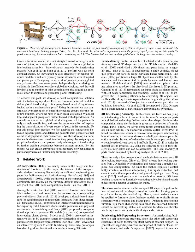
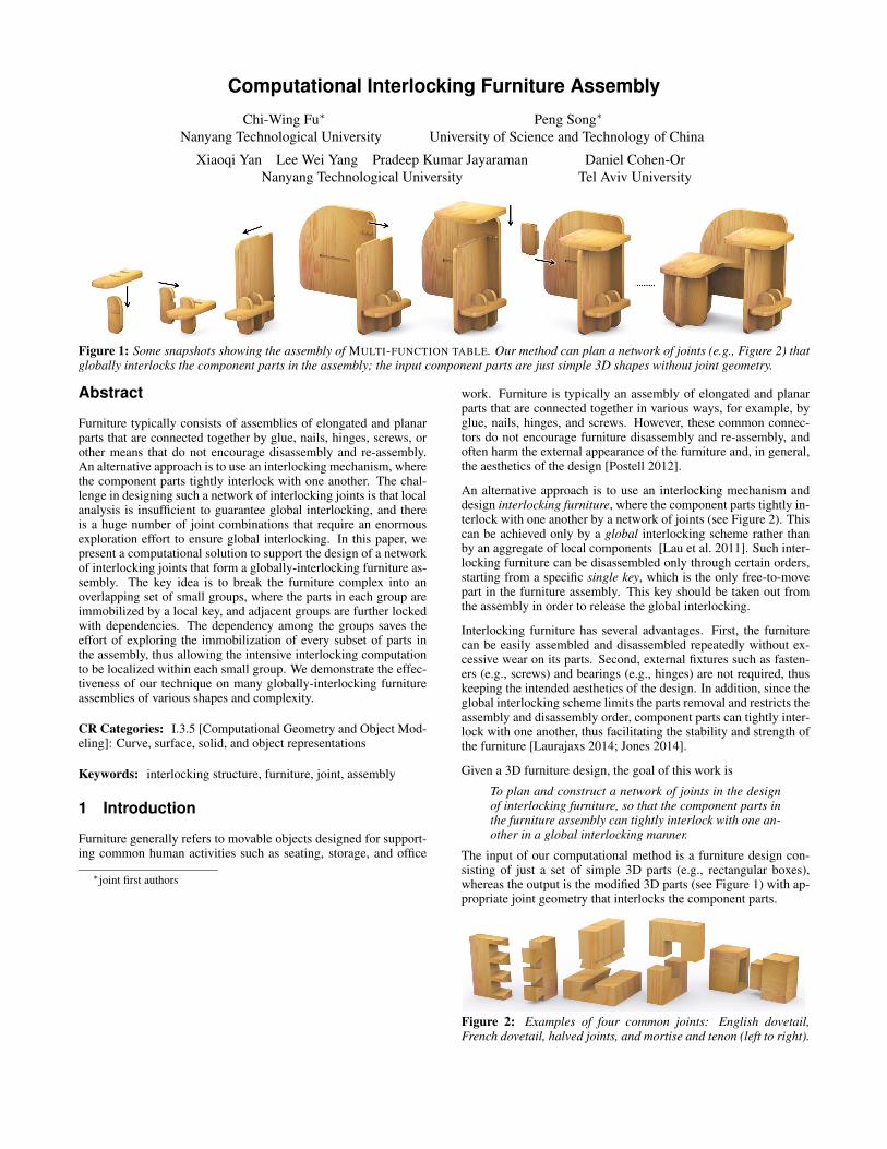
Figure 3: Overview of our approach. Given a furniture model, we first identify overlapping cycles in its parts-graph. Then, we iterativelyconstruct local interlocking groups (LIGs), i.e., G1, G2, and G3, with order dependency over the parts-graph by sharing certain parts (inparticular a key) between adjacent LIGs. Assuming each LIG is interlocked, we can achieve global interlocking over the entire assembly.
Given a furniture model, it is not straightforward to design a net-work of joints, or a network of connectors, to form a globally-interlocking assembly. State-of-the-art methods for interlockingpuzzles [Xin et al. 2011; Song et al. 2012] perform well for solidcompact shapes, but they cannot be used effectively for general fur-niture models, which are typically frame structures with elongatedand planar parts. Designing the network of joints requires a globalanalysis over the component parts. Independently considering lo-cal joints is insufficient to achieve global interlocking, and this willinvolve a huge number of joint combinations that require an enor-mous effort to explore and guarantee global interlocking.
To achieve our goal, we develop a novel computational solutionwith the following key ideas. First, we formulate a formal model todefine global interlocking. It is a group-based interlocking schemebacked up by a mathematical proof. Using this model, we can con-struct an overlapping set of small interlocking groups over the fur-niture complex, where the parts in each group are locked by a localkey, and adjacent groups are further locked with dependencies. Asa result, we can achieve global interlocking over all the parts withonly a single mobile key, and save the enormous effort of explor-ing the immobilization of every subset of parts in the assembly. Toput this model into practice, we first analyze the connections be-tween adjacent parts, and determine possible joint geometries thatcould be deployed at each connection. We then develop an itera-tive method to construct small interlocking groups by assigning ap-propriate local joints, and progressively achieve global interlockingby further creating dependency between adjacent groups. By thismeans, we can create appropriate joint geometry between adjacentparts and produce an interlocking furniture assembly.
2 Related Work
3D Fabrication. Below we mainly focus on the design and fab-rication of furniture. In this topic, the interest of the computeraided design community lies mainly on traditional engineering as-pects that facilitate models fabrication (e.g., Gustafsson [1995] andSmardzewski [1998]), while the interest of the computer graphicscommunity lies mainly on the furniture design: interactive meth-ods [Saul et al. 2011] and computational tools [Lau et al. 2011].
Among the works, Lau et al. [2011] converted furniture models intofabricatable parts and connectors for constructing correspondingphysical objects. Saul et al. [2011] developed a sketch-based inter-face for designing and building chairs fabricated from sheet materi-als. Umetani et al. [2012] proposed an interactive design frameworkfor exploring valid furniture shapes under geometric and physicalconstraints. Schwartzburg and Pauly [2013] proposed a computa-tional approach to generate 3D models (e.g., a chair) composed ofintersecting planar pieces. Schulz et al. [2014] presented an in-teractive design-by-example system for fabricating objects using aparameterized template representation. Koo et al. [2014] developedan interactive system to create functioning works-like prototypesbased on high-level functional relationships among 3D parts.
Fabrication by Parts. A number of related works focus on par-titioning a solid 3D shape into parts for 3D fabrication. Medellınet al. [2007] subdivided a 3D shape into parts based on a regu-lar grid. Hao et al. [2011] decomposed a large complex modelinto simpler 3D parts by using curvature-based partitioning. Luoet al. [2012] partitioned a large 3D object into smaller parts by pla-nar cuts, and then connected the parts by male and female con-nectors. Hildebrand et al. [2013] determined the optimal print-ing orientation to address the directional bias issue in 3D printing.Cignoni et al. [2014] represented an input shape as planar pieceswith slit-based fabrication and assembly. Vanek et al. [2014] im-proved the 3D printing efficiency by converting 3D objects intoshells and breaking them into parts that can be glued together. Zhouet al. [2014] converted a 3D object into a set of jointed parts that canbe folded into a box. Hu et al. [2014] decomposed a 2D/3D shapeinto a small number of parts that are approximately pyramidal.
3D Interlocking Assembly. In this work, we focus on designingan interlocking scheme to connect the furniture’s component partsin a globally-interlocking fashion rather than shape (furniture) de-composition, since the furniture is given as a collection of simplelogical parts. Below, we survey some recent computational meth-ods on interlocking. The pioneering work by Cutler [1978; 1994] isbased on exhaustive search to discover new six-piece interlockingburr structures; it took around two and a half years to complete theentire analysis. Instead of exhaustive search, some puzzle design-ers employed software such as BurrTools [Rover 2011] to assist themanual design process, i.e., using the software to test if their de-signs are interlocked and can be assembled. The local mobility ofparts can be analyzed by blocking analysis [Li et al. 2008].
There are only a few computational methods that can construct 3Dinterlocking structures. Xin et al. [2011] created interlocking puz-zles from 3D models by replicating and connecting a specific six-piece burr configuration, but since the method requires a centralbulky structure to achieve interlocking, it is highly restrictive, andcannot deal with complex shapes of general topology. Later, Songet al. [2012] developed a recursive method to construct 3D inter-locking structures by iteratively extracting polycube-shaped puzzlepieces from a general voxelized 3D shape.
The above works assume a solid compact 3D shape as input, so theinternal volume of the shape is used to create the blocking geom-etry for achieving the interlocking. Hence, these methods cannotbe applied to furniture since furniture models are typically framestructures with elongated and planar parts. Designing interlockingfurniture is a more challenging task since the designed furnitureshould be interlocking, stable, and aesthetic for daily use, therebyinvolving more constraints on the design and creation.
Fabricating Self-Supporting Structures. An interlocking furni-ture is a self-supporting structure, since like other self-supportingstructures, it holds together by itself without external support. Ageneral self-supporting structure is composed of parts or blocks likebricks, stones, and rods. Vouga et al. [2012] proposed to interac-
Figure 4: We iteratively assign joints between adjacent parts, e.g., group G1 in Figure 3, such that each joint immobilizes all directions ofassociated parts, except for one certain direction, e.g., joint J14 immobilizes P1 and P4 except +y and -y, respectively. The number of ONbits (in each six-bit mobility code) associated with the parts are reduced incrementally, indicating the parts interlocking in the assembly.
tively design self-supporting structures by using the thrust networkmethod. Panozzo et al. [2013] generated self-supporting masonrymodels from a user-provided height field. Liu et al. [2013] repre-sented a 3D self-supporting surface using a 2D regular triangula-tion for improving its geometry processing. De Goes et al. [2013]introduced a discrete theory of equilibrium for simplicial masonrystructures to facilitate their analysis and design. Song and Fu etal. [2013] proposed an interactive method for designing large recip-rocal frame structures with many sloping rods. Tang et al. [2014]solved geometric and structural form-finding with self-supportingpolyhedral meshes for architectural and industrial design. Deuss etal. [2014] constructed freeform self-supporting structures by usinga sparse set of chains connected to fixed anchor points.
The design of all these self-supporting structures, just like inter-locking furniture, requires a global analysis of all the components(i.e., blocks and parts). It should be stressed that blocks in self-supporting structures are connected by friction or mortar, whileparts in interlocking furniture are connected by blocking usingtheir own geometries in the joints. Furthermore, assembling self-supporting structures requires a dense formwork or chains, whichare difficult and tedious to construct, while assembling interlockingfurniture can be done easily with far less manual effort.
3 Overview
The input furniture design is given as a set of simple 3D parts,where adjacent parts may contact or intersect, see Figure 3 (left).To prepare such an input, we look for furniture designs by Googleimage search and use 3D Studio Max to arrange furniture parts withintersecting rectangular boxes to mimic a given furniture design.
The computational interlocking method that we present considersa simplified problem, where the parts potentially connect and onlymove along the main axes. Thus, each part is associated with a codeof six bits, representing the six main axial directions, where an ONbit indicates that the part is free to move along the associated ax-ial direction, and an OFF bit indicates that the part is immobilizedalong the associated axial direction. Initially, all parts of the assem-bly are associated with a 111111 code. Our algorithm iterativelyassigns a joint between adjacent parts. Each joint immobilizes cer-tain directions, so that all parts, except for a specific key, eventuallypossess a 000000 code, implying that they are immobilized in theassembly. Figure 4 illustrates this procedure on a group of parts,and shows how the assignment of joints incrementally reduces thenumber of ON bits associated with the parts of the assembly. Lateron, we shall elaborate on this algorithm and formalize it.
A parts-graph is an undirected graph, where nodes represent furni-ture parts and edges connect two contacting/intersecting parts (seeFigure 3 (left)). Given an initial parts-graph, we merge degree-1nodes in the graph with their adjacent parts since these danglingnodes cannot be interlocked. We also analyze and identify groupsof overlapping cycles in the parts-graph (see again Figure 3).
A local interlocking group (in short, LIG) is a connected subgraphin parts-graph, where parts are locked by a specific key in the group.
That is, after we assemble the parts in a LIG (in the absence of otherparts in the assembly), we cannot take out any part or any subset ofparts from the LIG, unless we first take out the key, which is theonly mobile part in the LIG. Thus, LIGs should include a cycle ofat least three parts, so that the parts in a LIG can be interlocked.
A joint-graph is an undirected graph with joints as nodes and partsas edges (see Figure 4 (right)). In the joint-graph, the directionnext to a node (joint) indicates the free axial direction that a jointimposes on the part. Since we consider joints that restrict parts tomove along a specific axial direction, adjacent parts at a joint arerestricted to move in opposite directions, e.g., +y and −y for P1
and P4, respectively, at joint J14 shown in the figure. Moreover,adjacent joints connected along an edge in the joint-graph shouldhave different axial directions in order to immobilize the associatedpart (except the key), e.g., P2 in Figure 4 (right): −y and −x.
The Formal Model. We formulate the problem of computing aninterlocking furniture as a problem of (i) forming LIGs that overlapone another over the parts-graph, and (ii) creating order dependencyto lock adjacent LIGs (see Figure 3).
Our objective is to achieve a global interlocking state, where allparts and all subsets of connected parts (except the key itself) inthe assembly are immobilized. This requires a global analysis toensure that (i) every furniture part is locked by a local key in itsown LIG(s), and (ii) every LIG is locked by some other adjacentLIG(s), except for the primary LIG (denoted by G1). Hence, G1
holds the primary key k1 that locks the entire assembly.
An LIG-graph is a directed acyclic graph (denoted by G) with LIGsas nodes (see Figure 3). Given Gi and Gj as two adjacent LIGs,there is a directed edge from Gj to Gi in G, if Gj depends on (andis locked by) Gi. That is, no part in Gj can be taken out before cer-tain part(s) in Gi (in particular, Gi’s key) has/have been taken out.In practice, such a dependency is created by overlapping adjacentLIGs with certain common parts (see Section 4 for detail). Exceptfor G1, every node in G should have at least one outgoing edge.Moreover, G should not have cycles, or cyclic dependency.
A Three-level Scheme. The formal model is a three-level globalinterlocking scheme: parts, LIGs, and the entire assembly. Basedon it, we can progressively assemble the furniture based on thedependency order in G: starting from the LIGs without incomingedges till reaching G1 and then ending with the primary key k1.
To approach the problem, we could ignore the middle level, anddirectly compute global interlocking with parts. However, directlycomputing interlocking is highly nontrivial since for n parts, wehave to consider 2n combinations (subsets) of parts, and ensuretheir immobilization (except the key itself) in the assembly, e.g.,subsets {P1,P2} and {P3,P4} in Figure 4. Note that if we can par-tition the parts-graph into two subgraphs, such that all edges acrossthe two subgraphs (i.e., joints between parts across the two parti-tions) share the same axial direction, the associated parts in a sub-graph can be taken out altogether to break the assembly. Moreover,we have to explore many different choices of joints for blockingeach part in the assembly. This would result in an overly large num-
ber of possible joints configurations and interlocking computationfor each configuration. Hence, directly working with parts involvesa huge search space, and is highly non-scalable.
Our three-level formal model overcomes the above issues by form-ing and connecting small LIGs with order dependency (see Fig-ure 3). We can, therefore, moderate the search space in computingthe interlocking locally in each LIG. Unlike the parts-graph, whoseedges are undirected connections, we cannot arbitrarily break Gsince its edges are constrained to the assembly/disassembly orderbetween adjacent LIGs. In other words, the order dependencyavoids the need to consider the mobility of all LIG subsets, andthe exploration of subset (of parts) immobilization. Please refer toAppendix for the related mathematical proof.
High-level Algorithm. Our computational solution has three ma-jor steps: (i) we construct a parts-graph to represent the input furni-ture, and then analyze and identify possible free axial directions be-tween every pair of adjacent parts (see Section 5); (ii) we iterativelyconstruct LIGs with appropriate joints to achieve local interlockingand order dependency among the overlapping LIGs, starting fromthe primary key to the entire parts-graph (see Section 6); and (iii)we generate the 3D model of each part by adapting the chosen jointgeometry to modify the part (see Section 6).
4 Formal Model
This section details our formal model and the various conditions forachieving global interlocking. In Section 6, we present the proce-dure that plans and assigns joints in a given furniture complex basedon these conditions. Let us start with the following notations:
• Gi is the ith LIG that we construct over a parts-graph; it has alocal key ki and a set of parts Si, for i ∈ {1, 2, ..., n}, wheren is the total number of LIGs (nodes) in G.
• S is the set of all the parts in G, i.e., S = ∪ni=1Si, and Ri is the
(residual) set of parts from Si to Sn, so R1 = S and Rn = Sn.
• Si and Si are the subsets of parts in Si that share with pre-ceding and succeeding LIGs, respectively, i.e., Si = Si ∩(∪i−1
j=1Sj) and Si = Si ∩ Ri+1. So, S1 = ∅ and Sn = ∅.
• Si = Si\(Si ∪ Si) are parts in Gi, not shared with other LIGs.
• Given two adjacent parts PA and PB connected by a joint (seeFigure 9 for examples), we denote d(PA,PB) as the free axialdirection of PA imposed by its joint connection with PB, sod(PA,PB) = -d(PB,PA), since PA and PB move in oppositedirections in order to separate from each other.
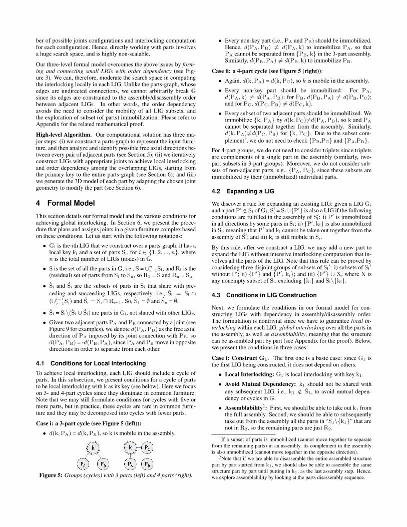
4.1 Conditions for Local InterlockingTo achieve local interlocking, each LIG should include a cycle ofparts. In this subsection, we present conditions for a cycle of partsto be local interlocking with k as its key (see below). Here we focuson 3- and 4-part cycles since they dominate in common furniture.Note that we may still formulate conditions for cycles with five ormore parts, but in practice, these cycles are rare in common furni-ture and they may be decomposed into cycles with fewer parts.
Case i: a 3-part cycle (see Figure 5 (left)):• d(k,PA) = d(k,PB), so k is mobile in the assembly.
Figure 5: Groups (cycles) with 3 parts (left) and 4 parts (right).
• Every non-key part (i.e., PA and PB) should be immobilized.Hence, d(PA,PB) 6= d(PA, k) to immobilize PA, so thatPA cannot be separated from {PB, k} in the 3-part assembly.Similarly, d(PB,PA) 6= d(PB, k) to immobilize PB.
Case ii: a 4-part cycle (see Figure 5 (right)):• Again, d(k,PA) = d(k,PC), so k is mobile in the assembly.
• Every non-key part should be immobilized: For PA,d(PA, k) 6= d(PA,PB); for PB, d(PB,PA) 6= d(PB,PC);and for PC, d(PC,PB) 6= d(PC, k).
• Every subset of two adjacent parts should be immobilized. Weimmobilize {k, PA} by d(k,PC) 6=d(PA,PB), so k and PA
cannot be separated together from the assembly. Similarly,d(k,PA) 6=d(PC,PB) for {k, PC}. Due to the subset com-plement1, we do not need to check {PB,PC} and {PA,PB}.
For 4-part groups, we do not need to consider triplets since tripletsare complements of a single part in the assembly (similarly, two-part subsets in 3-part groups). Moreover, we do not consider sub-sets of non-adjacent parts, e.g., {PA, PC}, since these subsets areimmobilized by their (immobilized) individual parts.
4.2 Expanding a LIG
We discover a rule for expanding an existing LIG: given a LIG Gi
and a part P′ /∈ Si of Gi, S′i = Si∪{P′} is also a LIG if the followingconditions are fulfilled in the assembly of S′i: i) P′ is immobilizedin all directions by some parts in Si; ii) {P′, ki} is also immobilizedin Si, meaning that P′ and ki cannot be taken out together from theassembly of S′i; and iii) ki is still mobile in Si.
By this rule, after we construct a LIG, we may add a new part toexpand the LIG without intensive interlocking computation that in-volves all the parts of the LIG. Note that this rule can be proved byconsidering three disjoint groups of subsets of Si
′: i) subsets of Si′
without P′; ii) {P′} and {P′, ki}; and iii) {P′} ∪ X, where X isany nonempty subset of Si, excluding {ki} and Si\{ki}.
4.3 Conditions in LIG Construction
Next, we formulate the conditions in our formal model for con-structing LIGs with dependency in assembly/disassembly order.The formulation is nontrivial since we have to guarantee local in-terlocking within each LIG, global interlocking over all the parts inthe assembly, as well as assemblability, meaning that the structurecan be assembled part by part (see Appendix for the proof). Below,we present the conditions in three cases:
Case i: Construct G1. The first one is a basic case: since G1 isthe first LIG being constructed, it does not depend on others.
• Local Interlocking: G1 is local interlocking with key k1.
• Avoid Mutual Dependency: k1 should not be shared withany subsequent LIG, i.e., k1 /∈ S1, to avoid mutual depen-dency or cycles in G.
• Assemblability2: First, we should be able to take out k1 fromthe full assembly. Second, we should be able to subsequentlytake out from the assembly all the parts in “S1\{k1}” that arenot in R2, so the remaining parts are just R2.
1If a subset of parts is immobilized (cannot move together to separatefrom the remaining parts) in an assembly, its complement in the assemblyis also immobilized (cannot move together in the opposite direction).
2Note that if we are able to disassemble the entire assembled structurepart by part started from k1, we should also be able to assemble the samestructure part by part until putting in k1, as the last assembly step. Hence,we explore assemblability by looking at the parts disassembly sequence.

Figure 6: Left: There is no dependency (locking) between Gi andGj if they share only a key; we may separate Gi altogether fromGj\{kj}. Right: we propose to share a key and at least one non-key part P∗, so that one of the groups (Gi) can lock the other (Gj).
See Figure 3 for an example G1, whose key is not shared with otherLIGs to avoid mutual dependency; see the joints configuration inFigure 4, G1 is local interlocking while it can be assembled.
Case ii: Construct Gj that shares parts with only onepreviously-constructed LIG, say Gi (j>i), but not others. Be-sides the first two conditions in case i, we have the following con-ditions for constructing Gj; in particular, Gj should depend on Gi:
• New Part(s): At least one part in Gj is not included in anypreviously-constructed LIGs, i.e., |Sj| > |Sj|, so that we canconstruct LIGs that eventually cover all the parts.
• Assemblability: Before we unlock (take out local key kj) anddisassemble Gj, we should have unlocked all the LIGs that areconstructed before Gj and taken out from the entire assemblyall the parts that are not in Rj. Now, similar to case i, we en-sure that kj can be taken out from Rj, subsequently followedby all the parts (taken out one by one) in “Sj\{kj}” that arenot in Rj+1, so the remaining parts are just Rj+1.
• Dependency on Gi: Gj should share at least two parts (in-cluding kj) with Gi, so that every subset of parts in Gj be-comes immobilized until we unlock Gi by taking out ki.
Take an assembly of two LIGs (Gi and Gj) as an example. If theyshare only one part, which is kj, parts in Gi may move altogetherwith kj and separate from Gj even though we have not unlocked Gi
by taking out its key (see Figure 6 (left)). By sharing an additionalnon-key part between them (see P∗ in Figure 6 (right)), we cannotseparate Gi from Gj since {kj, P∗} is an immobilized subset in Gj,which is a LIG. Moreover, ki should not be shared with Gj to avoidmutual dependency (see the second condition in case i).
Case iii: Construct Gj that shares parts with multiplepreviously-constructed LIGs. This case is the same as case ii,except for the following condition:
• Dependency. Gj should depend on at least one previously-constructed LIG by sharing its local key kj and at least onenon-key part of it with a previously-constructed LIG.
Note that Gj may depend on more than one previously-constructedLIG by sharing its key and a non-key part as above; here we mayshare different non-key parts of Gj with these previous LIGs.
Assembly/Disassembly order. By constructing LIGs based onthe formal model, the parts disassembly order naturally follows theLIG construction order: after taking out k1 from the full assembly,we can take out parts in S1\R2, k2, parts in S2\R3, etc., until Sn.Reversing this gives the parts assembly order, see Figure 3 (right).
5 Joint Analysis
To apply the formal model to create an interlocking furniture as-sembly given a furniture design, we first need to analyze the partconnections in the design to find out possible joint geometries (eachwith a free axial direction) that can be deployed at each connection(Section 5) before we proceed to construct LIGs (Section 6).
Figure 7: The 13 cases of ICO vector (A), in which 2D boxes A(yellow) and B (blue) intersect; ordered by +x, −z, −x, and +z.
Figure 8: The 23 cases of ICO vector (A), in which 3D boxes A(yellow) and B (blue) intersect: ordered by +x, −z, −x, +z, +y,and −y. The arrows show the possible axial movement directionsof A over all joint geometries that we may choose to use.
Figure 9: Example joint geometries for some cases in Figure 8.
5.1 Joint Lookup Table
To support efficient joint analysis, we prepare a precomputed tablecalled the joint lookup table, which is indexed by the ICO vector:
ICO (Inside-Common-Outside) Vector. Given two axis-alignedboxes A and B with intersection volume VAB , their ICO vectorshave six elements, corresponding to main axial directions. Takingthe +x direction as an example with fA and fB as the +x faces ofA and B, respectively, the +x element of A’s ICO vector is: I if fA (but not fB) is on +x face of VAB ,
C if both fA and fB are on VAB , andO if fA is not on VAB .
By repeating the above check for other faces, we can form A’s ICOvector (see Figure 7 for cases with 2D boxes). Note that the ICOvectors of A and B are complements of each other (see Figure 7(right)): interchanging I and O and keeping C unchanged.
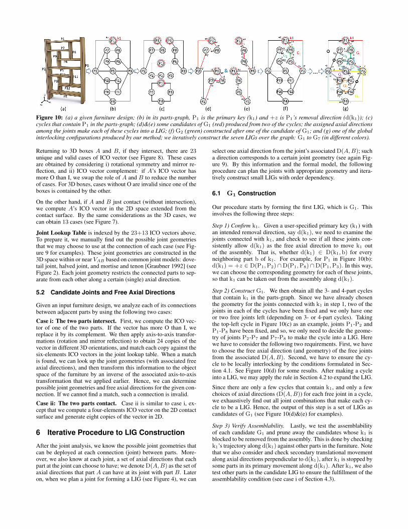
Figure 10: (a) a given furniture design; (b) in its parts-graph, P1 is the primary key (k1) and +z is P1’s removal direction (d(k1)); (c)cycles that contain P1 in the parts-graph; (d)&(e) some candidates of G1 (red) produced from two of the cycles; the assigned axial directionsamong the joints make each of these cycles into a LIG; (f) G2 (green) constructed after one of the candidate of G1; and (g) one of the globalinterlocking configurations produced by our method; we iteratively construct the seven LIGs over the graph: G1 to G7 (in different colors).
Returning to 3D boxes A and B, if they intersect, there are 23unique and valid cases of ICO vector (see Figure 8). These casesare obtained by considering i) rotational symmetry and mirror re-flection, and ii) ICO vector complement: if A’s ICO vector hasmore O than I, we swap the role of A and B to reduce the numberof cases. For 3D boxes, cases without O are invalid since one of theboxes is contained by the other.
On the other hand, if A and B just contact (without intersection),we compute A’s ICO vector in the 2D space extended from thecontact surface. By the same considerations as the 3D cases, wecan obtain 13 cases (see Figure 7).
Joint Lookup Table is indexed by the 23+13 ICO vectors above.To prepare it, we manually find out the possible joint geometriesthat we may choose to use at the connection of each case (see Fig-ure 9 for examples). These joint geometries are constructed in the3D space within or near VAB based on common joint models: dove-tail joint, halved joint, and mortise and tenon [Graubner 1992] (seeFigure 2). Each joint geometry restricts the connected parts to sep-arate from each other along a certain (single) axial direction.
5.2 Candidate Joints and Free Axial Directions
Given an input furniture design, we analyze each of its connectionsbetween adjacent parts by using the following two cases:
Case i: The two parts intersect. First, we compute the ICO vec-tor of one of the two parts. If the vector has more O than I, wereplace it by its complement. We then apply axis-to-axis transfor-mations (rotation and mirror reflection) to obtain 24 copies of thevector in different 3D orientations, and match each copy against thesix-elements ICO vectors in the joint lookup table. When a matchis found, we can look up the joint geometries (with associated freeaxial directions), and then transform this information to the objectspace of the furniture by an inverse of the associated axis-to-axistransformation that we applied earlier. Hence, we can determinepossible joint geometries and free axial directions for the given con-nection. If we cannot find a match, such a connection is invalid.
Case ii: The two parts contact. Case ii is similar to case i, ex-cept that we compute a four-elements ICO vector on the 2D contactsurface and generate eight copies of the vector in 2D.
6 Iterative Procedure to LIG Construction
After the joint analysis, we know the possible joint geometries thatcan be deployed at each connection (joint) between parts. More-over, we also know at each joint, a set of axial directions that eachpart at the joint can choose to have; we denote D(A,B) as the set ofaxial directions that part A can have at its joint with part B. Lateron, when we plan a joint for forming a LIG (see Figure 4), we can
select one axial direction from the joint’s associated D(A,B); sucha direction corresponds to a certain joint geometry (see again Fig-ure 9). By this information and the formal model, the followingprocedure can plan the joints with appropriate geometry and itera-tively construct small LIGs with order dependency.
6.1 G1 Construction
Our procedure starts by forming the first LIG, which is G1. Thisinvolves the following three steps:
Step 1) Confirm k1. Given a user-specified primary key (k1) withan intended removal direction, say d(k1), we need to examine thejoints connected with k1, and check to see if all these joints con-sistently allow d(k1) as the free axial direction to move k1 outof the assembly. That is, whether d(k1) ∈ D(k1, b) for everyneighboring part b of k1. For example, for P1 in Figure 10(b):d(k1) = +z ∈ D(P1,P2)∩D(P1,P8)∩D(P1,P3). In this way,we can choose the corresponding geometry for each of these joints,so that k1 can be taken out from the assembly along d(k1).
Step 2) Construct G1. We then obtain all the 3- and 4-part cyclesthat contain k1 in the parts-graph. Since we have already chosenthe geometry for the joints connected with k1 in step 1, two of thejoints in each of the cycles have been fixed and we only have oneor two free joints left (depending on 3- or 4-part cycles). Takingthe top-left cycle in Figure 10(c) as an example, joints P1-P2 andP1-P8 have been fixed, and so, we only need to decide the geome-try of joints P2-P7 and P7-P8 to make the cycle into a LIG. Herewe have to consider the following two requirements. First, we haveto choose the free axial direction (and geometry) of the free jointsfrom the associated D(A,B). Second, we have to ensure the cy-cle to be locally interlocking by the conditions formulated in Sec-tion 4.1. See Figure 10(d) for some results. After making a cycleinto a LIG, we may apply the rule in Section 4.2 to expand the LIG.
Since there are only a few cycles that contain k1, and only a fewchoices of axial directions (D(A,B)) for each free joint in a cycle,we exhaustively find out all joint combinations that make each cy-cle to be a LIG. Hence, the output of this step is a set of LIGs ascandidates of G1 (see Figure 10(d)&(e) for examples).
Step 3) Verify Assemblability. Lastly, we test the assemblabilityof each candidate G1 and prune away the candidates whose k1 isblocked to be removed from the assembly. This is done by checkingk1’s trajectory along d(k1) against other parts in the furniture. Notethat we also consider and check secondary translational movementalong axial directions perpendicular to d(k1), after k1 is stopped bysome parts in its primary movement along d(k1). After k1, we alsotest other parts in the candidate LIG to ensure the fulfillment of theassemblability condition (see case i of Section 4.3).
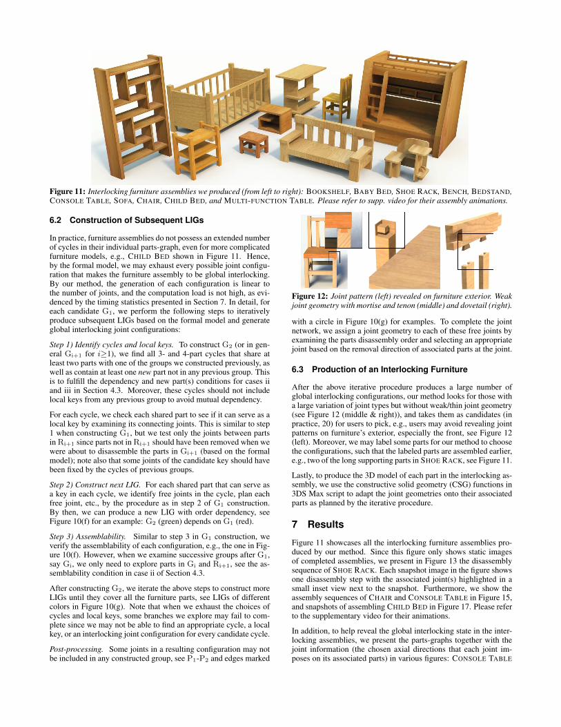
Figure 11: Interlocking furniture assemblies we produced (from left to right): BOOKSHELF, BABY BED, SHOE RACK, BENCH, BEDSTAND,CONSOLE TABLE, SOFA, CHAIR, CHILD BED, and MULTI-FUNCTION TABLE. Please refer to supp. video for their assembly animations.
6.2 Construction of Subsequent LIGs
In practice, furniture assemblies do not possess an extended numberof cycles in their individual parts-graph, even for more complicatedfurniture models, e.g., CHILD BED shown in Figure 11. Hence,by the formal model, we may exhaust every possible joint configu-ration that makes the furniture assembly to be global interlocking.By our method, the generation of each configuration is linear tothe number of joints, and the computation load is not high, as evi-denced by the timing statistics presented in Section 7. In detail, foreach candidate G1, we perform the following steps to iterativelyproduce subsequent LIGs based on the formal model and generateglobal interlocking joint configurations:
Step 1) Identify cycles and local keys. To construct G2 (or in gen-eral Gi+1 for i≥1), we find all 3- and 4-part cycles that share atleast two parts with one of the groups we constructed previously, aswell as contain at least one new part not in any previous group. Thisis to fulfill the dependency and new part(s) conditions for cases iiand iii in Section 4.3. Moreover, these cycles should not includelocal keys from any previous group to avoid mutual dependency.
For each cycle, we check each shared part to see if it can serve as alocal key by examining its connecting joints. This is similar to step1 when constructing G1, but we test only the joints between partsin Ri+1 since parts not in Ri+1 should have been removed when wewere about to disassemble the parts in Gi+1 (based on the formalmodel); note also that some joints of the candidate key should havebeen fixed by the cycles of previous groups.
Step 2) Construct next LIG. For each shared part that can serve asa key in each cycle, we identify free joints in the cycle, plan eachfree joint, etc., by the procedure as in step 2 of G1 construction.By then, we can produce a new LIG with order dependency, seeFigure 10(f) for an example: G2 (green) depends on G1 (red).
Step 3) Assemblability. Similar to step 3 in G1 construction, weverify the assemblability of each configuration, e.g., the one in Fig-ure 10(f). However, when we examine successive groups after G1,say Gi, we only need to explore parts in Gi and Ri+1, see the as-semblability condition in case ii of Section 4.3.
After constructing G2, we iterate the above steps to construct moreLIGs until they cover all the furniture parts, see LIGs of differentcolors in Figure 10(g). Note that when we exhaust the choices ofcycles and local keys, some branches we explore may fail to com-plete since we may not be able to find an appropriate cycle, a localkey, or an interlocking joint configuration for every candidate cycle.
Post-processing. Some joints in a resulting configuration may notbe included in any constructed group, see P1-P2 and edges marked
Figure 12: Joint pattern (left) revealed on furniture exterior. Weakjoint geometry with mortise and tenon (middle) and dovetail (right).
with a circle in Figure 10(g) for examples. To complete the jointnetwork, we assign a joint geometry to each of these free joints byexamining the parts disassembly order and selecting an appropriatejoint based on the removal direction of associated parts at the joint.
6.3 Production of an Interlocking Furniture
After the above iterative procedure produces a large number ofglobal interlocking configurations, our method looks for those witha large variation of joint types but without weak/thin joint geometry(see Figure 12 (middle & right)), and takes them as candidates (inpractice, 20) for users to pick, e.g., users may avoid revealing jointpatterns on furniture’s exterior, especially the front, see Figure 12(left). Moreover, we may label some parts for our method to choosethe configurations, such that the labeled parts are assembled earlier,e.g., two of the long supporting parts in SHOE RACK, see Figure 11.
Lastly, to produce the 3D model of each part in the interlocking as-sembly, we use the constructive solid geometry (CSG) functions in3DS Max script to adapt the joint geometries onto their associatedparts as planned by the iterative procedure.
7 Results
Figure 11 showcases all the interlocking furniture assemblies pro-duced by our method. Since this figure only shows static imagesof completed assemblies, we present in Figure 13 the disassemblysequence of SHOE RACK. Each snapshot image in the figure showsone disassembly step with the associated joint(s) highlighted in asmall inset view next to the snapshot. Furthermore, we show theassembly sequences of CHAIR and CONSOLE TABLE in Figure 15,and snapshots of assembling CHILD BED in Figure 17. Please referto the supplementary video for their animations.
In addition, to help reveal the global interlocking state in the inter-locking assemblies, we present the parts-graphs together with thejoint information (the chosen axial directions that each joint im-poses on its associated parts) in various figures: CONSOLE TABLE
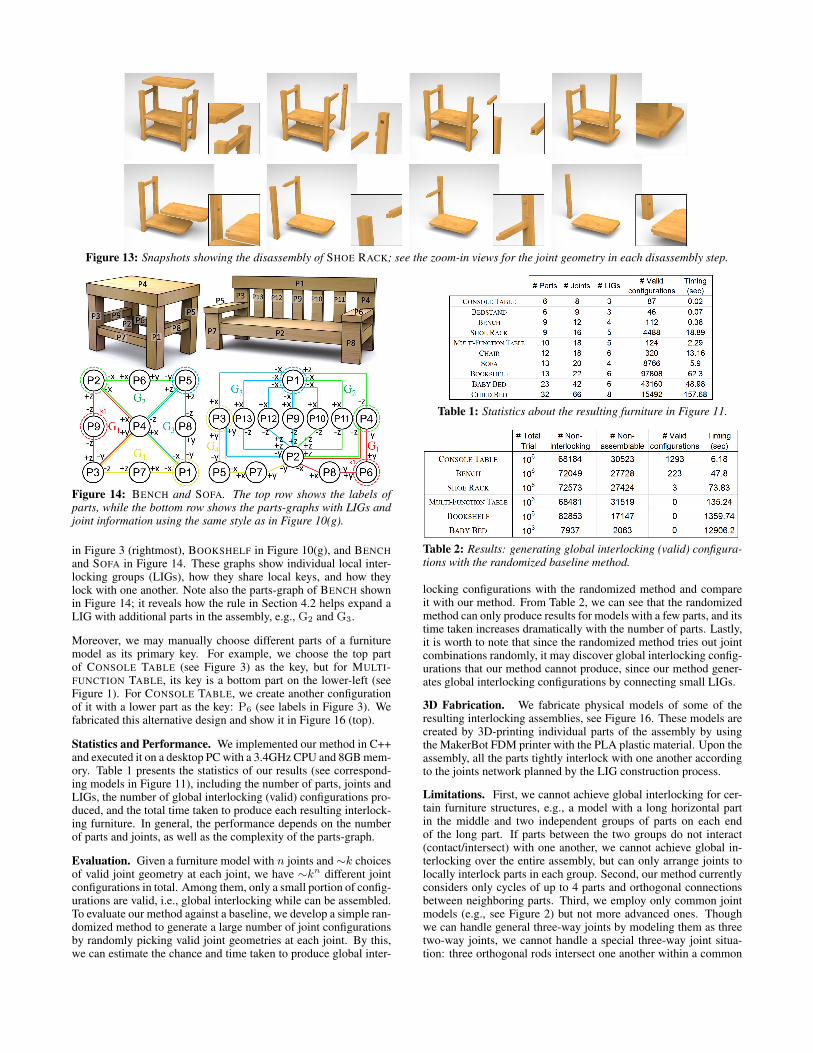
Figure 13: Snapshots showing the disassembly of SHOE RACK; see the zoom-in views for the joint geometry in each disassembly step.
Figure 14: BENCH and SOFA. The top row shows the labels ofparts, while the bottom row shows the parts-graphs with LIGs andjoint information using the same style as in Figure 10(g).
in Figure 3 (rightmost), BOOKSHELF in Figure 10(g), and BENCHand SOFA in Figure 14. These graphs show individual local inter-locking groups (LIGs), how they share local keys, and how theylock with one another. Note also the parts-graph of BENCH shownin Figure 14; it reveals how the rule in Section 4.2 helps expand aLIG with additional parts in the assembly, e.g., G2 and G3.
Moreover, we may manually choose different parts of a furnituremodel as its primary key. For example, we choose the top partof CONSOLE TABLE (see Figure 3) as the key, but for MULTI-FUNCTION TABLE, its key is a bottom part on the lower-left (seeFigure 1). For CONSOLE TABLE, we create another configurationof it with a lower part as the key: P6 (see labels in Figure 3). Wefabricated this alternative design and show it in Figure 16 (top).
Statistics and Performance. We implemented our method in C++and executed it on a desktop PC with a 3.4GHz CPU and 8GB mem-ory. Table 1 presents the statistics of our results (see correspond-ing models in Figure 11), including the number of parts, joints andLIGs, the number of global interlocking (valid) configurations pro-duced, and the total time taken to produce each resulting interlock-ing furniture. In general, the performance depends on the numberof parts and joints, as well as the complexity of the parts-graph.
Evaluation. Given a furniture model with n joints and∼k choicesof valid joint geometry at each joint, we have ∼kn different jointconfigurations in total. Among them, only a small portion of config-urations are valid, i.e., global interlocking while can be assembled.To evaluate our method against a baseline, we develop a simple ran-domized method to generate a large number of joint configurationsby randomly picking valid joint geometries at each joint. By this,we can estimate the chance and time taken to produce global inter-
Table 1: Statistics about the resulting furniture in Figure 11.
Table 2: Results: generating global interlocking (valid) configura-tions with the randomized baseline method.
locking configurations with the randomized method and compareit with our method. From Table 2, we can see that the randomizedmethod can only produce results for models with a few parts, and itstime taken increases dramatically with the number of parts. Lastly,it is worth to note that since the randomized method tries out jointcombinations randomly, it may discover global interlocking config-urations that our method cannot produce, since our method gener-ates global interlocking configurations by connecting small LIGs.
3D Fabrication. We fabricate physical models of some of theresulting interlocking assemblies, see Figure 16. These models arecreated by 3D-printing individual parts of the assembly by usingthe MakerBot FDM printer with the PLA plastic material. Upon theassembly, all the parts tightly interlock with one another accordingto the joints network planned by the LIG construction process.
Limitations. First, we cannot achieve global interlocking for cer-tain furniture structures, e.g., a model with a long horizontal partin the middle and two independent groups of parts on each endof the long part. If parts between the two groups do not interact(contact/intersect) with one another, we cannot achieve global in-terlocking over the entire assembly, but can only arrange joints tolocally interlock parts in each group. Second, our method currentlyconsiders only cycles of up to 4 parts and orthogonal connectionsbetween neighboring parts. Third, we employ only common jointmodels (e.g., see Figure 2) but not more advanced ones. Thoughwe can handle general three-way joints by modeling them as threetwo-way joints, we cannot handle a special three-way joint situa-tion: three orthogonal rods intersect one another within a common
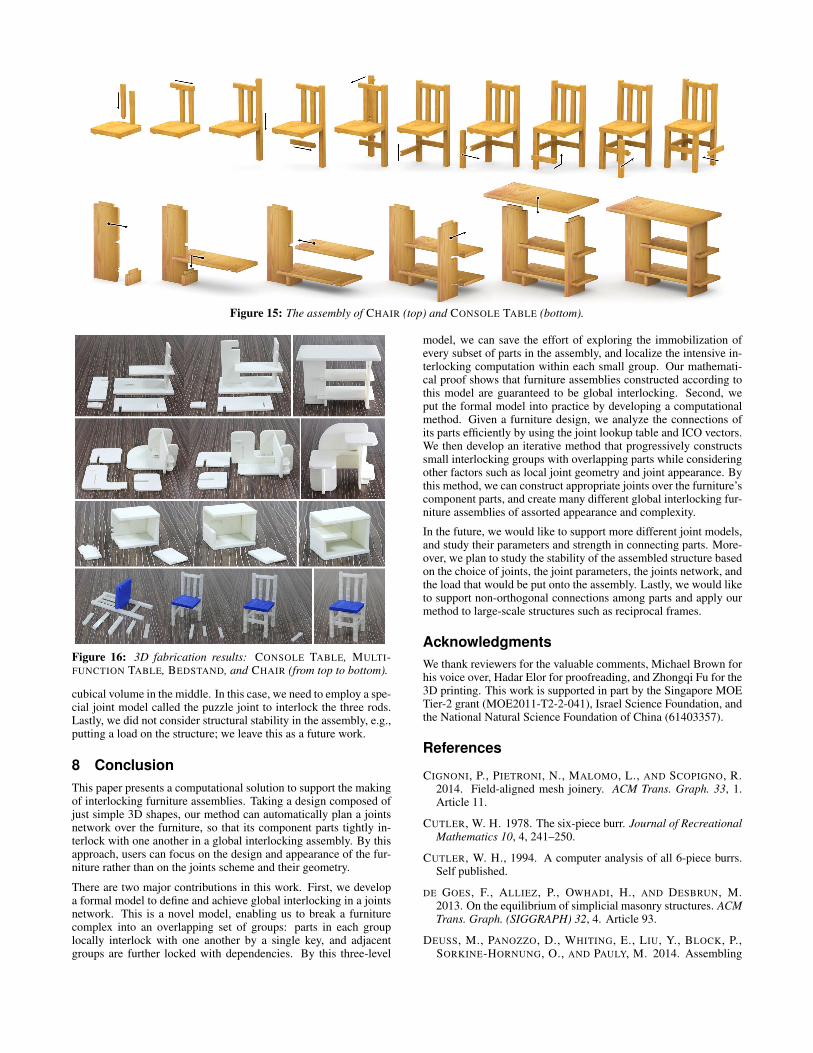
Figure 15: The assembly of CHAIR (top) and CONSOLE TABLE (bottom).
Figure 16: 3D fabrication results: CONSOLE TABLE, MULTI-FUNCTION TABLE, BEDSTAND, and CHAIR (from top to bottom).
cubical volume in the middle. In this case, we need to employ a spe-cial joint model called the puzzle joint to interlock the three rods.Lastly, we did not consider structural stability in the assembly, e.g.,putting a load on the structure; we leave this as a future work.
8 ConclusionThis paper presents a computational solution to support the makingof interlocking furniture assemblies. Taking a design composed ofjust simple 3D shapes, our method can automatically plan a jointsnetwork over the furniture, so that its component parts tightly in-terlock with one another in a global interlocking assembly. By thisapproach, users can focus on the design and appearance of the fur-niture rather than on the joints scheme and their geometry.
There are two major contributions in this work. First, we developa formal model to define and achieve global interlocking in a jointsnetwork. This is a novel model, enabling us to break a furniturecomplex into an overlapping set of groups: parts in each grouplocally interlock with one another by a single key, and adjacentgroups are further locked with dependencies. By this three-level
model, we can save the effort of exploring the immobilization ofevery subset of parts in the assembly, and localize the intensive in-terlocking computation within each small group. Our mathemati-cal proof shows that furniture assemblies constructed according tothis model are guaranteed to be global interlocking. Second, weput the formal model into practice by developing a computationalmethod. Given a furniture design, we analyze the connections ofits parts efficiently by using the joint lookup table and ICO vectors.We then develop an iterative method that progressively constructssmall interlocking groups with overlapping parts while consideringother factors such as local joint geometry and joint appearance. Bythis method, we can construct appropriate joints over the furniture’scomponent parts, and create many different global interlocking fur-niture assemblies of assorted appearance and complexity.
In the future, we would like to support more different joint models,and study their parameters and strength in connecting parts. More-over, we plan to study the stability of the assembled structure basedon the choice of joints, the joint parameters, the joints network, andthe load that would be put onto the assembly. Lastly, we would liketo support non-orthogonal connections among parts and apply ourmethod to large-scale structures such as reciprocal frames.
AcknowledgmentsWe thank reviewers for the valuable comments, Michael Brown forhis voice over, Hadar Elor for proofreading, and Zhongqi Fu for the3D printing. This work is supported in part by the Singapore MOETier-2 grant (MOE2011-T2-2-041), Israel Science Foundation, andthe National Natural Science Foundation of China (61403357).
References
CIGNONI, P., PIETRONI, N., MALOMO, L., AND SCOPIGNO, R.2014. Field-aligned mesh joinery. ACM Trans. Graph. 33, 1.Article 11.
CUTLER, W. H. 1978. The six-piece burr. Journal of RecreationalMathematics 10, 4, 241–250.
CUTLER, W. H., 1994. A computer analysis of all 6-piece burrs.Self published.
DE GOES, F., ALLIEZ, P., OWHADI, H., AND DESBRUN, M.2013. On the equilibrium of simplicial masonry structures. ACMTrans. Graph. (SIGGRAPH) 32, 4. Article 93.
DEUSS, M., PANOZZO, D., WHITING, E., LIU, Y., BLOCK, P.,SORKINE-HORNUNG, O., AND PAULY, M. 2014. Assembling
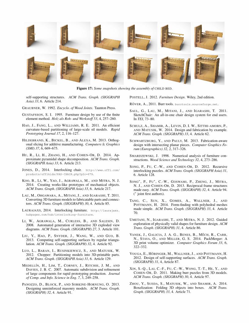
Figure 17: Some snapshots showing the assembly of CHILD BED.
self-supporting structures. ACM Trans. Graph. (SIGGRAPHAsia) 33, 6. Article 214.
GRAUBNER, W. 1992. Encyclo. of Wood Joints. Taunton Press.
GUSTAFSSON, S. I. 1995. Furniture design by use of the finiteelement method. Holz als Roh- und Werkstoff 53, 4, 257–260.
HAO, J., FANG, L., AND WILLIAMS, R. E. 2011. An efficientcurvature-based partitioning of large-scale stl models. RapidPrototyping Journal 17, 2, 116–127.
HILDEBRAND, K., BICKEL, B., AND ALEXA, M. 2013. Orthog-onal slicing for additive manufacturing. Computers & Graphics(SMI) 37, 6, 669–675.
HU, R., LI, H., ZHANG, H., AND COHEN-OR, D. 2014. Ap-proximate pyramidal shape decomposition. ACM Trans. Graph.(SIGGRAPH Asia) 33, 6. Article 213.
JONES, D., 2014. Interlocking chair. http://www.offi.com/
products/offikids/PAS-CHAIR.php?p2c=679.
KOO, B., LI, W., YAO, J., AGRAWALA, M., AND MITRA, N. J.2014. Creating works-like prototypes of mechanical objects.ACM Trans. Graph. (SIGGRAPH Asia) 33, 6. Article 217.
LAU, M., OHGAWARA, A., MITANI, J., AND IGARASHI, T. 2011.Converting 3D furniture models to fabricatable parts and connec-tors. ACM Trans. Graph. (SIGGRAPH) 30, 4. Article 85.
LAURAJAXS, 2014. Interlocking furniture. http://laurajaxs.
hubpages.com/hub/interlocking-furniture.
LI, W., AGRAWALA, M., CURLESS, B., AND SALESIN, D.2008. Automated generation of interactive 3D exploded viewdiagrams. ACM Trans. Graph. (SIGGRAPH) 27, 3. Article 101.
LIU, Y., HAO, P., SNYDER, J., WANG, W., AND GUO, B.2013. Computing self-supporting surfaces by regular triangu-lation. ACM Trans. Graph. (SIGGRAPH) 32, 4. Article 92.
LUO, L., BARAN, I., RUSINKIEWICZ, S., AND MATUSIK, W.2012. Chopper: Partitioning models into 3D-printable parts.ACM Trans. Graph. (SIGGRAPH Asia) 31, 6. Article 129.
MEDELLIN, H., LIM, T., CORNEY, J., RITCHIE, J. M., ANDDAVIES, J. B. C. 2007. Automatic subdivision and refinementof large components for rapid prototyping production. Journalof Comp. and Info. Science in Eng. 7, 3, 249–258.
PANOZZO, D., BLOCK, P., AND SORKINE-HORNUNG, O. 2013.Designing unreinforced masonry models. ACM Trans. Graph.(SIGGRAPH) 32, 4. Article 91.
POSTELL, J. 2012. Furniture Design. Wiley, 2nd edition.
ROVER, A., 2011. Burr tools. burrtools.sourceforge.net.
SAUL, G., LAU, M., MITANI, J., AND IGARASHI, T. 2011.SketchChair: An all-in-one chair design system for end users.In TEI, 73–80.
SCHULZ, A., SHAMIR, A., LEVIN, D. I. W., SITTHI-AMORN, P.,AND MATUSIK, W. 2014. Design and fabrication by example.ACM Trans. Graph. (SIGGRAPH) 33, 4. Article 62.
SCHWARTZBURG, Y., AND PAULY, M. 2013. Fabrication-awaredesign with intersecting planar pieces. Computer Graphics Fo-rum (Eurographics) 32, 2, 317–326.
SMARDZEWSKI, J. 1998. Numerical analysis of furniture con-structions. Wood Science and Technology 32, 4, 273–286.
SONG, P., FU, C.-W., AND COHEN-OR, D. 2012. Recursiveinterlocking puzzles. ACM Trans. Graph. (SIGGRAPH Asia) 31,6. Article 128.
SONG∗ , P., FU∗ , C.-W., GOSWAMI, P., ZHENG, J., MITRA,N. J., AND COHEN-OR, D. 2013. Reciprocal frame structuresmade easy. ACM Trans. Graph. (SIGGRAPH) 32, 4. Article 94.(∗ joint first authors).
TANG, C., SUN, X., GOMES, A., WALLNER, J., ANDPOTTMANN, H. 2014. Form-finding with polyhedral meshesmade simple. ACM Trans. Graph. (SIGGRAPH) 33, 4. Article70.
UMETANI, N., IGARASHI, T., AND MITRA, N. J. 2012. Guidedexploration of physically valid shapes for furniture design. ACMTrans. Graph. (SIGGRAPH) 31, 4. Article 86.
VANEK, J., GALICIA, J. A. G., BENES, B., MECH, R., CARR,N., STAVA, O., AND MILLER, G. S. 2014. PackMerger: A3D print volume optimizer. Computer Graphics Forum 33, 6,322–332.
VOUGA, E., HOBINGER, M., WALLNER, J., AND POTTMANN, H.2012. Design of self-supporting surfaces. ACM Trans. Graph.(SIGGRAPH) 31, 4, Article 87.
XIN, S.-Q., LAI, C.-F., FU, C.-W., WONG, T.-T., HE, Y., ANDCOHEN-OR, D. 2011. Making burr puzzles from 3D models.ACM Trans. Graph. (SIGGRAPH) 30, 4. Article 97.
ZHOU, Y., SUEDA, S., MATUSIK, W., AND SHAMIR, A. 2014.Boxelization: Folding 3D objects into boxes. ACM Trans.Graph. (SIGGRAPH) 33, 4. Article 71.
Appendix
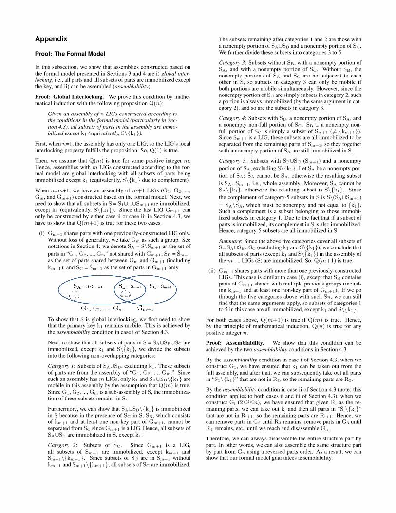
Proof: The Formal Model
In this subsection, we show that assemblies constructed based onthe formal model presented in Sections 3 and 4 are i) global inter-locking, i.e., all parts and all subsets of parts are immobilized exceptthe key, and ii) can be assembled (assemblability).
Proof: Global Interlocking. We prove this condition by mathe-matical induction with the following proposition Q(n):
Given an assembly of n LIGs constructed according tothe conditions in the formal model (particularly in Sec-tion 4.3), all subsets of parts in the assembly are immo-bilized except k1 (equivalently, S\{k1}).
First, when n=1, the assembly has only one LIG, so the LIG’s localinterlocking property fulfills the proposition. So, Q(1) is true.
Then, we assume that Q(m) is true for some positive integer m.Hence, assemblies with m LIGs constructed according to the for-mal model are global interlocking with all subsets of parts beingimmobilized except k1 (equivalently, S\{k1} due to complement).
When n=m+1, we have an assembly of m+1 LIGs (G1, G2, ...,Gm, and Gm+1) constructed based on the formal model. Next, weneed to show that all subsets in S = S1∪...∪Sm+1 are immobilized,except k1 (equivalently, S\{k1}). Since the last LIG Gm+1 canonly be constructed by either case ii or case iii in Section 4.3, wehave to show that Q(m+1) is true for these two cases.
(i) Gm+1 shares parts with one previously-constructed LIG only.Without loss of generality, we take Gm as such a group. Seenotations in Section 4: we denote SA = S\Sm+1 as the set ofparts in “G1, G2, ..., Gm” not shared with Gm+1; SB = Sm+1
as the set of parts shared between Gm and Gm+1 (includingkm+1); and SC = Sm+1 as the set of parts in Gm+1 only.
To show that S is global interlocking, we first need to showthat the primary key k1 remains mobile. This is achieved bythe assemblability condition in case i of Section 4.3.
Next, to show that all subsets of parts in S = SA∪SB∪SC areimmobilized, except k1 and S\{k1}, we divide the subsetsinto the following non-overlapping categories:
Category 1: Subsets of SA∪SB, excluding k1. These subsetsof parts are from the assembly of “G1, G2, ..., Gm.” Sincesuch an assembly has m LIGs, only k1 and SA∪SB\{k1} aremobile in this assembly by the assumption that Q(m) is true.Since G1, G2, ..., Gm is a sub-assembly of S, the immobiliza-tion of these subsets remains in S.
Furthermore, we can show that SA∪SB\{k1} is immobilizedin S because in the presence of SC in S, SB, which consistsof km+1 and at least one non-key part of Gm+1, cannot beseparated from SC since Gm+1 is a LIG. Hence, all subsets ofSA∪SB are immobilized in S, except k1.
Category 2: Subsets of SC. Since Gm+1 is a LIG,all subsets of Sm+1 are immobilized, except km+1 andSm+1\{km+1}. Since subsets of SC are in Sm+1 withoutkm+1 and Sm+1\{km+1}, all subsets of SC are immobilized.
The subsets remaining after categories 1 and 2 are those witha nonempty portion of SA∪SB and a nonempty portion of SC.We further divide these subsets into categories 3 to 5.
Category 3: Subsets without SB, with a nonempty portion ofSA, and with a nonempty portion of SC. Without SB, thenonempty portions of SA and SC are not adjacent to eachother in S, so subsets in category 3 can only be mobile ifboth portions are mobile simultaneously. However, since thenonempty portion of SC are simply subsets in category 2, sucha portion is always immobilized (by the same argument in cat-egory 2), and so are the subsets in category 3.
Category 4: Subsets with SB, a nonempty portion of SA, anda nonempty non-full portion of SC. SB ∪ a nonempty non-full portion of SC is simply a subset of Sm+1 ( 6= {km+1}).Since Sm+1 is a LIG, these subsets are all immobilized to beseparated from the remaining parts of Sm+1, so they togetherwith a nonempty portion of SA are still immobilized in S.
Category 5: Subsets with SB∪SC (Sm+1) and a nonemptyportion of SA, excluding S\{k1}. Let SA be a nonempty por-tion of SA: SA cannot be SA, otherwise the resulting subsetis SA∪Sm+1, i.e., whole assembly. Moreover, SA cannot beSA\{k1}, otherwise the resulting subset is S\{k1}. Sincethe complement of category-5 subsets in S is S\(SA∪Sm+1)= SA\SA, which must be nonempty and not equal to {k1}.Such a complement is a subset belonging to those immobi-lized subsets in category 1. Due to the fact that if a subset ofparts is immobilized, its complement in S is also immobilized.Hence, category-5 subsets are all immobilized in S.
Summary: Since the above five categories cover all subsets ofS=SA∪SB∪SC (excluding k1 and S\{k1}), we conclude thatall subsets of parts (except k1 and S\{k1}) in the assembly ofthe m+1 LIGs (S) are immobilized. So, Q(m+1) is true.
(ii) Gm+1 shares parts with more than one previously-constructedLIGs. This case is similar to case (i), except that SB containsparts of Gm+1 shared with multiple previous groups (includ-ing km+1 and at least one non-key part of Gm+1). If we gothrough the five categories above with such SB, we can stillfind that the same arguments apply, so subsets of categories 1to 5 in this case are all immobilized, except k1 and S\{k1}.
For both cases above, Q(m+1) is true if Q(m) is true. Hence,by the principle of mathematical induction, Q(n) is true for anypositive integer n.
Proof: Assemblability. We show that this condition can beachieved by the two assemblability conditions in Section 4.3.
By the assemblability condition in case i of Section 4.3, when weconstruct G1, we have ensured that k1 can be taken out from thefull assembly, and after that, we can subsequently take out all partsin “S1\{k1}” that are not in R2, so the remaining parts are R2.
By the assemblability condition in case ii of Section 4.3 (note: thiscondition applies to both cases ii and iii of Section 4.3), when weconstruct Gi (2≤i≤n), we have ensured that given Ri as the re-maining parts, we can take out ki and then all parts in “Si\{ki}”that are not in Ri+1, so the remaining parts are Ri+1. Hence, wecan remove parts in G2 until R3 remains, remove parts in G3 untilR4 remains, etc., until we reach and disassemble Gn.
Therefore, we can always disassemble the entire structure part bypart. In other words, we can also assemble the same structure partby part from Gn using a reversed parts order. As a result, we canshow that our formal model guarantees assemblability.


![Interlocking Principles[1]](https://img.dokumen.tips/doc/110x75/577ccd121a28ab9e788b6c16/interlocking-principles1.jpg)