Embed Size (px)
Citation preview
������������������
����� ������ �� ����� ���� ����� �����������������
������������� ����������������������� �!����� "
��#��!$�SAFETY RULES see manual n°511927 / Spare parts list and maintenance instructions for compressors
�
�
���������������������������������������First apposition of the EC marking: 2014
This document must not be disclosed or reproduced without permission from MIL'S. Failure to respect this requirement may lead to prosecution.
��%&'�#���()�*(+,"%""%������(,���
� �
-� ����� .�������� � /0�� �� � 1�� .���1��� .������������� �������� �������������� �!����� " ��#��!$��
�����'"# %&'"%�# �� ���(+,"%""%2��.�� ,
�
���������
SECTION 1 INTRODUCTION 4
1.1 SPECIFICATION PLATES............................................................................................................................ 4
SECTION 2 DESCRIPTION OF AN AIR PLANT HOSPITAIR PACK D – SCREW 5
2.1 SCHEMATIC DIAGRAM .............................................................................................................................. 5 2.2 COMPRESSORS ....................................................................................................................................... 5 2.3 MANIFOLD .............................................................................................................................................. 6 2.4 AIR TREATMENT SYSTEM .......................................................................................................................... 7 2.5 RECEIVER .............................................................................................................................................. 7 2.6 FINAL FILTRATION ................................................................................................................................... 7
SECTION 3 CHOICE OF THE PREMISES 8
3.1 ENVIRONNEMENTAL CONDITIONS .............................................................................................................. 8 3.2 PLANNED USE ......................................................................................................................................... 8 3.3 RECOMMENDATION DURING INSTALLATION ................................................................................................. 8 3.4 INSTALLATION ......................................................................................................................................... 8 3.5 VENTILATION OF THE PREMISES ................................................................................................................ 9 3.6 FIRE .................................................................................................................................................... 11 3.7 WRAPPING ........................................................................................................................................... 11
SECTION 4 INSTALLATIONS 12
4.1 DIMENSIONS ......................................................................................................................................... 12 4.2 ELECTRIC POWER SUPPLY ...................................................................................................................... 13 4.3 CONNECTIONS TO THE PNEUMATIC NETWORK ........................................................................................... 14
SECTION 5 CONNECTIONS 16
5.1 INSTALLATION OF HOSPITAIR OR AIRMIL’S UNITS, TYPE G OR PACK ..................................................... 16 5.2 COMPÉTENCIES, TRAINING AND QUALIFICATIONS ...................................................................................... 16 5.3 BEGINNING OF THE WORK ...................................................................................................................... 16 5.4 OPTIONNAL TANK .................................................................................................................................. 17 5.5 PIPES, FLEXIBLE HOSES AND FITTINGS ..................................................................................................... 17 5.6 BRAZING OF PIPING ............................................................................................................................... 18 5.7 VERIFICATIONS DURING AND AFTER THE INSTALLATION OF THE PIPES ......................................................... 18
SECTION 6 RUNNING OPERATION 19
6.1 FIRST STEP ........................................................................................................................................... 19 6.2 SWITCHING ON ...................................................................................................................................... 19
SECTION 7 SETTINGS 20
7.1 SETTING PRESSURE ............................................................................................................................... 20 7.2 FLEXO TIME DURATION ........................................................................................................................ 20 7.3 TOP-UP TIME DURATION ......................................................................................................................... 20 7.4 HYGROMETRY ....................................................................................................................................... 20
SECTION 8 ALARMS 20
SECTION 9 CLEANING AND MAINTENANCE 21
9.1 ELECTRONIC VENT VALVE TEST ............................................................................................................... 22 9.2 PRESSURE INDICATOR ........................................................................................................................... 22 9.3 HYGROMETRY PROBE ............................................................................................................................ 22 9.4 PAR FILTER REPLACEMENT OF DUPLEX PARALLEL FINAL FILTRATION ......................................................... 22 9.5 MECHANICAL BACK-UP DEVICE ............................................................................................................... 22 9.6 DISCHARGE SYSTEM .............................................................................................................................. 22 9.7 NETWORK ALARM.................................................................................................................................. 22 9.8 SAFETY RELIEF VALVE ........................................................................................................................... 23
SECTION 10 PROCOM3 24V OPTION WITH BACKUP 23
10.1 DESCRIPTION ........................................................................................................................................ 23 10.2 START-UP ............................................................................................................................................ 23 10.3 MAINTENANCE ...................................................................................................................................... 23
SECTION 11 TEST PRESSURE 24
-� ����� .�������� � /0�� �� � 1�� .���1��� .������������� �������� �������������� �!����� " ��#��!$� �
�� ���(+,"%""%2��.�� , %&'"%�# ����"'"#
�
SECTION 12 PROTECTION AGAINST OVERPRESSURE 24
SECTION 13 TRAINING 24
SECTION 14 CLEANING 24
14.1 UNITS CLEANING ................................................................................................................................... 24
SECTION 15 ELECTROMAGNETIC COMPATIBILITY 25
� �
-� ����� .�������� � /0�� �� � 1�� .���1��� .������������� �������� �������������� �!����� " ��#��!$��
����3'"# %&'"%�# �� ���(+,"%""%2��.�� ,
�
�� ������������������ ���������������� �� ��
�
Symbols are used in these instructions to help you understand them and to indicate particular points which you need to act upon or consider. Those symbols are:
Reading symbol: to refer to the operator manual / instructions manual. Warning symbol: This symbol means that failure to observe this point could lead to injury and possibly damage to the machine. It serves as a special reminder about regulations and/or the correct implementation of certain precautions. Danger symbol: This symbol represents the DIN 4844 symbol (hazard warning); it warns of a hazard which could result in death or injury, along with damage to the machine. This symbol must be observed by all personnel working on this machine. Regulations on safety in the workplace must be observed. Environmental protection symbol: This symbol serves as a reminder to sort waste during maintenance operations, to store it in a safe place, and to dispose of it with due care for the environment.
Dustbin on wheels barred of a cross symbol: This symbol indicates that the equipment should not be thrown with domestic waste and is subject to selective collection. Non-ionizing radiation hazard symbol: This pictogram informs of a risk or a danger related to non-ionizing radiations
General remark: If used in accordance with their intended purpose, units bearing the CE mark will satisfy the essential requirements of directive 93/42/EEC, relative to medical devices and, where necessary, to essential requirements of the directive 2014/68/EU, relative to pressure equipment.
Those units, when installed in accordance with these instructions, comply with the provisions of currently applicable European Directives and harmonised standards. However, your attention is drawn to the fact that a unit with only one compressor or only one vacuum pump cannot be used without an emergency backup device: gas backup or other fixed or mobile unit.
To ensure personal safety and to avoid any damage to equipment, it is essential to follow the instructions contained in this document and any other documentation provided with the device, and particularly the instructions on “Safe Practice”.
-� ����� .�������� � /0�� �� � 1�� .���1��� .������������� �������� �������������� �!����� " ��#��!$� �
�� ���(+,"%""%2��.�� , %&'"%�# ����4'"#
�
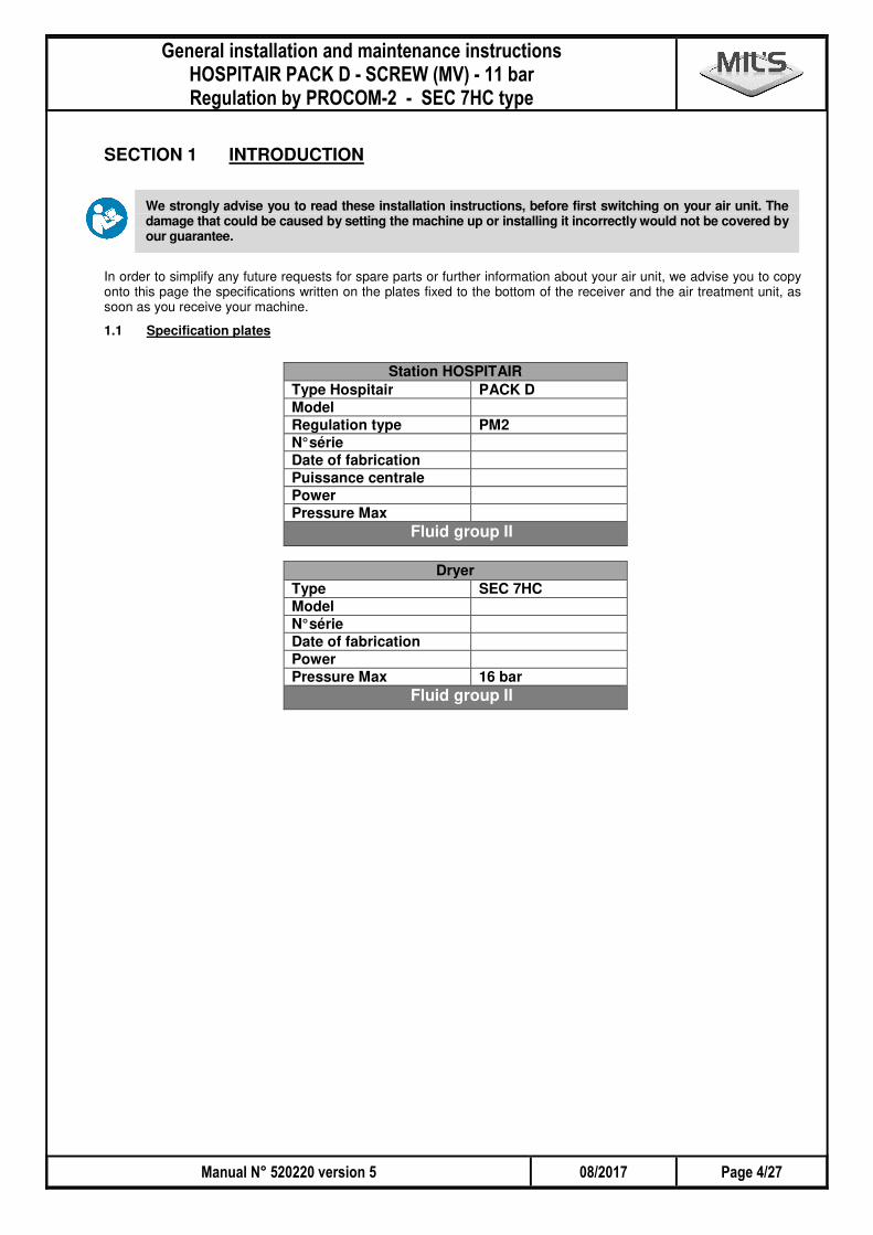
SECTION 1 INTRODUCTION
We strongly advise you to read these installation instructions, before first switching on your air unit. The damage that could be caused by setting the machine up or installing it incorrectly would not be covered by our guarantee.
In order to simplify any future requests for spare parts or further information about your air unit, we advise you to copy onto this page the specifications written on the plates fixed to the bottom of the receiver and the air treatment unit, as soon as you receive your machine.
1.1 Specification plates
Station HOSPITAIR Type Hospitair PACK D Model Regulation type PM2 N° série Date of fabrication Puissance centrale Power Pressure Max
Fluid group II
Dryer Type SEC 7HC Model N° série Date of fabrication Power Pressure Max 16 bar
Fluid group II
� �
-� ����� .�������� � /0�� �� � 1�� .���1��� .������������� �������� �������������� �!����� " ��#��!$��
����,'"# %&'"%�# �� ���(+,"%""%2��.�� ,
�
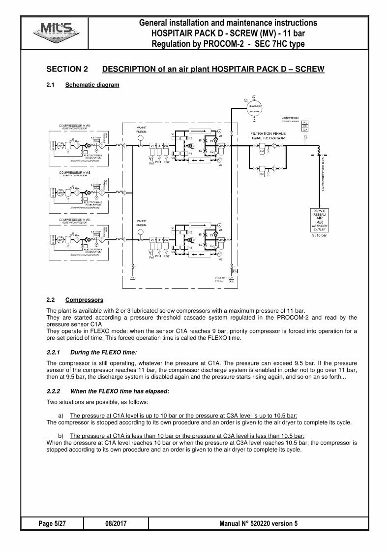
SECTION 2 DESCRIPTION of an air plant HOSPITAIR PACK D – SCREW
2.1 Schematic diagram
2.2 Compressors
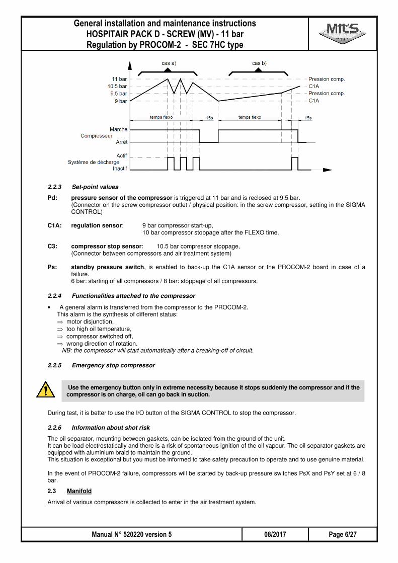
The plant is available with 2 or 3 lubricated screw compressors with a maximum pressure of 11 bar. They are started according a pressure threshold cascade system regulated in the PROCOM-2 and read by the pressure sensor C1A They operate in FLEXO mode: when the sensor C1A reaches 9 bar, priority compressor is forced into operation for a pre-set period of time. This forced operation time is called the FLEXO time.
2.2.1 During the FLEXO time:
The compressor is still operating, whatever the pressure at C1A. The pressure can exceed 9.5 bar. If the pressure sensor of the compressor reaches 11 bar, the compressor discharge system is enabled in order not to go over 11 bar, then at 9.5 bar, the discharge system is disabled again and the pressure starts rising again, and so on an so forth...
2.2.2 When the FLEXO time has elapsed:
Two situations are possible, as follows:
a) The pressure at C1A level is up to 10 bar or the pressure at C3A level is up to 10.5 bar: The compressor is stopped according to its own procedure and an order is given to the air dryer to complete its cycle.
b) The pressure at C1A is less than 10 bar or the pressure at C3A level is less than 10.5 bar: When the pressure at C1A level reaches 10 bar or when the pressure at C3A level reaches 10.5 bar, the compressor is stopped according to its own procedure and an order is given to the air dryer to complete its cycle.
-� ����� .�������� � /0�� �� � 1�� .���1��� .������������� �������� �������������� �!����� " ��#��!$� �
�� ���(+,"%""%2��.�� , %&'"%�# ����5'"#
�
2.2.3 Set-point values
Pd: pressure sensor of the compressor is triggered at 11 bar and is reclosed at 9.5 bar. (Connector on the screw compressor outlet / physical position: in the screw compressor, setting in the SIGMA CONTROL)
C1A: regulation sensor: 9 bar compressor start-up, 10 bar compressor stoppage after the FLEXO time. C3: compressor stop sensor: 10.5 bar compressor stoppage, (Connector between compressors and air treatment system) Ps: standby pressure switch, is enabled to back-up the C1A sensor or the PROCOM-2 board in case of a
failure. 6 bar: starting of all compressors / 8 bar: stoppage of all compressors.
2.2.4 Functionalities attached to the compressor
• A general alarm is transferred from the compressor to the PROCOM-2. This alarm is the synthesis of different status: ⇒ motor disjunction, ⇒ too high oil temperature,
⇒ compressor switched off, ⇒ wrong direction of rotation.
NB: the compressor will start automatically after a breaking-off of circuit.
2.2.5 Emergency stop compressor
Use the emergency button only in extreme necessity because it stops suddenly the compressor and if the compressor is on charge, oil can go back in suction.
During test, it is better to use the I/O button of the SIGMA CONTROL to stop the compressor.
2.2.6 Information about shot risk
The oil separator, mounting between gaskets, can be isolated from the ground of the unit. It can be load electrostatically and there is a risk of spontaneous ignition of the oil vapour. The oil separator gaskets are equipped with aluminium braid to maintain the ground. This situation is exceptional but you must be informed to take safety precaution to operate and to use genuine material. In the event of PROCOM-2 failure, compressors will be started by back-up pressure switches PsX and PsY set at 6 / 8 bar.
2.3 Manifold
Arrival of various compressors is collected to enter in the air treatment system.
� �
-� ����� .�������� � /0�� �� � 1�� .���1��� .������������� �������� �������������� �!����� " ��#��!$��
����#'"# %&'"%�# �� ���(+,"%""%2��.�� ,
�
2.4 Air treatment system
The air treatment system is composed of two identical lines: one in service, the other at rest. The inversion of this service/rest status is done according to the operation time or a fault (hygrometry or beko drain). Each air treatment line is composed of:
⇒ An isolating pneumatic valve,
⇒ A back-up pressure switch Ps (X or Y), ⇒ A cyclone/filter fitted with an electronic air vent valve BEKO12 (BKX or BKY) with an alarm contact in case of
failure, ⇒ A micronic filter, then a submicronic filter both equipped with condensate mechanical drain,
⇒ An adsorption dryer with 3 levels of air treatment: � Molecular sieve to remove CO2 and humidity, � Activated carbon to remove oil vapours and odours, � Hopcalite to remove CO.
Each air treatment system is designed to support the flow rate of one compressor. When two compressors are running, the two dryers are running.
2.5 Receiver
Service conditions: The service conditions are specified on the receiver identification plate. The operating pressure should never exceed the service pressure. The following minimum and maximum temperatures shall be complied with: 0 to 600 litres: Tmin = -10°C 600 to 2000 litres: T min = 0°C Tmax = 60°C Tmax = 50°C
These temperature values are given as a function of the capacity and only apply to the pressure receivers used with our HOSPITAIR products.
Purpose of use: These are single pressure devices designed to contain air or nitrogen. Installation and maintenance: The receiver must be installed in neutral, normal and current atmosphere and in places which are not likely to involve a rise in temperature of the device exceeding the temperature of service; it must be connected to ground. Access for check must be easy. Incidents are always possible (exhaust of valve, leakage on drain or valve, etc...) so it's better to avoid the installation of a device in an attended site, or near fragile devices. To check its interior state, the receiver must be visited regularly and according to the regulations in force in the country where it is installed. A depth control must be practiced regularly with adequate means (ultrasound, magnetic...). Fixing and fastening of receivers must be made while taking care to avoid all forced and tensions and to damp out all vibrations, even non-visible. The base of the receiver will have to support the weight of the receiver, including in situation of tests. In performing inspections, visits and periodical tests, we remind users to comply with the legislation in force where the tanks are in use in their country. The equipment must not be modified without the manufacturer's prior approval.
In complement of the indications hereafter, refer to the instruction manual provided with each receiver.
The receivers and their accessories must be protected from freezing and the fire. Use adequate handling and lifting system and take care not to damage the receiver or its components. Before proceeding to the inspection and/or maintenance operations on the receiver and its components, make sure that this one is completely drained (internal pressure equal to the atmospheric pressure). Not to carry out a welding or modifications (drilling, heating with a flame,…) on the parts under pressure of the receiver. The connection of the receiver with the installation must be carried out with flexible connections in order to avoid all vibrations. Take care that the receiver is always provided with its security accessories and its inspecting devices. In the event of damage of the device, check by calling upon a specialist, that the receiver can be used in full safety.
2.6 Final filtration
Before being delivered in the customer network, the air goes through a last filtration. Simple filtration or duplex filtration version is available. It is composed of:
⇒ one particle filter PAR,
⇒ an analysis connector to check the quality of the generated air, ⇒ a non-return valve.
-� ����� .�������� � /0�� �� � 1�� .���1��� .������������� �������� �������������� �!����� " ��#��!$� �
�� ���(+,"%""%2��.�� , %&'"%�# ����&'"#
�
The air enters in two sets at the same time and each set can be "by-passed" for the maintenance operations with isolating valves. NB: in option, pressure regulators can be installed after the final filtration. After the final filtration, the plant can be isolated from the network with an isolating valve and a network alarm sensor connector (C2A sensor) is available.
SECTION 3 CHOICE OF THE PREMISES
3.1 Environnemental conditions
Storage temperature: +2°C to +60°C Humidity: 30 to 80% relative humidity The medical air production plant must be installed in an area that is clean, not humid, in a non-saline environment, free of dust.
3.2 Planned use
The medical air production plant is intended for use in health care establishments in France and abroad. It can be used to supply the main network with medical air.
3.3 Recommendation during installation
A back-up supply source composed of high-pressure cylinders (or cylinder racks) of medical air is recommended to ensure the continuity of the supply, even in the event of a major electrical failure. The enclosures (interior or exterior) for the medical air feed systems must comply with the following requirements:
� When an enclosure is located near a source of heat such as an oven, incinerator or a boiler room, the construction must ensure that the temperature of the premises does not exceed 40°C.
� If a system for heating the premises is installed, no point in contact with the air must exceed 225°C . � An enclosure must not be located within 3 m of an electric transformer, � Enclosures must not be next to fuel storage tanks, � Enclosures must have a concrete floor � The fences and the walls must be at least 1.75m high � The premises or zones occupied by the generators must not be used for other purposes.
The medical air production plant must be protected against shocks from passing vehicles, carts, etc. Standards NFS99-175 (§ 5-7-3), ISO 10083, ISO 7396-1 (§ 5-8) indicate that an air plant must not be installed in the same room as the concentrators of O2
, or cylinders of non-cryogenic gases and liquids.
When choosing the location for a medical air production plant, it is necessary to take into account the potential risks (of contamination and fire for example). Drainage systems must be installed in this location. The air admission(s) of the compressors must be in a place with minimum contamination by exhaust from an internal combustion engines (for example, automobiles), exhaust from vacuum systems, exhaust from medical gas distribution networks, from anesthesia gas exhaust systems, exhaust from ventilation systems and other sources of contamination. The admissions must have means to prevent the entry of insects, debris and water. It is important to take into account the potential effects of the prevailing winds on the location of the admission(s).
3.4 Installation
Before any handling of the machines, see section §3.7
The installer bears the full responsibility for the environment where the product will be installed. Means for fighting fire, to protect the medical air production plant against shocks, four weather, floods, earthquakes and corrosion must be installed by the installer. All of the constructions, whether buildings, civil engineering structures or earthworks, are at the expense of the operator and/or of the installer.
The medical air production plant will only function properly on a horizontal surface that can bear the total mass of the system and its accessories. Be sure to install the medical air production plant and its accessories such that the nameplates are visible and accessible.
� �
-� ����� .�������� � /0�� �� � 1�� .���1��� .������������� �������� �������������� �!����� " ��#��!$��
����6'"# %&'"%�# �� ���(+,"%""%2��.�� ,
�
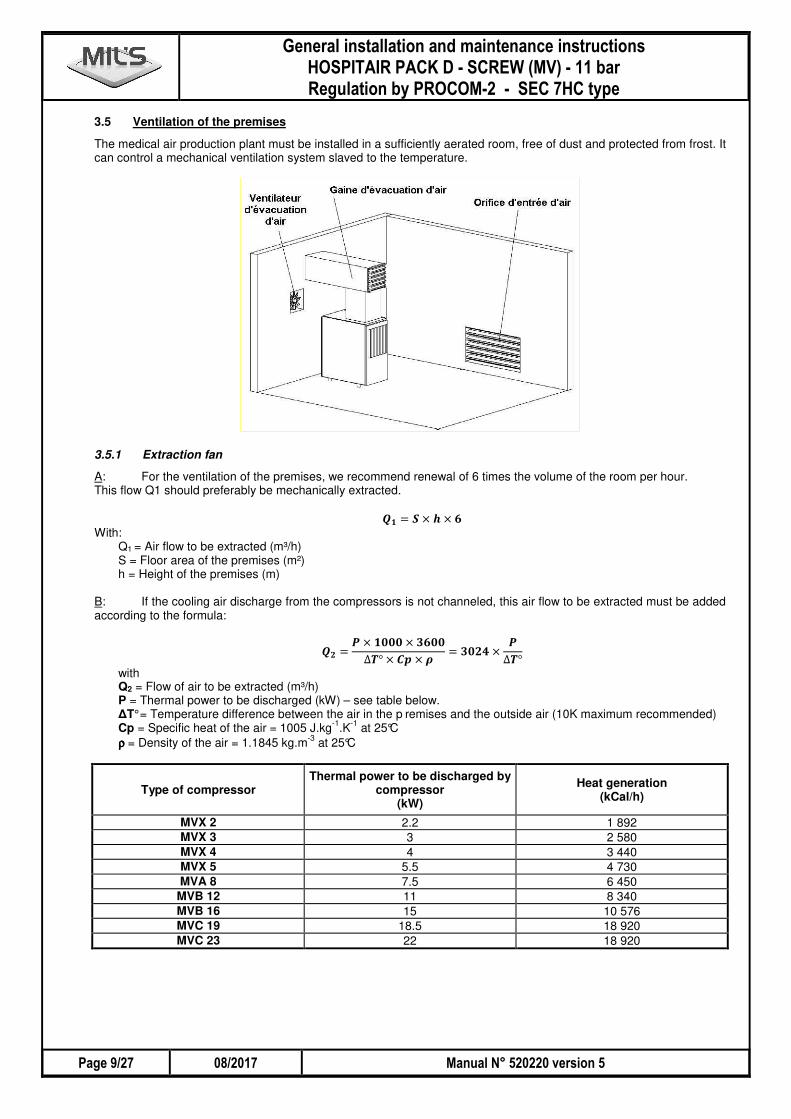
3.5 Ventilation of the premises
The medical air production plant must be installed in a sufficiently aerated room, free of dust and protected from frost. It can control a mechanical ventilation system slaved to the temperature.
3.5.1 Extraction fan
A: For the ventilation of the premises, we recommend renewal of 6 times the volume of the room per hour. This flow Q1 should preferably be mechanically extracted.
�� = � × � × �
With: Q1 = Air flow to be extracted (m³/h) S = Floor area of the premises (m²) h = Height of the premises (m)
B: If the cooling air discharge from the compressors is not channeled, this air flow to be extracted must be added according to the formula:
�� = × � × ��
∆ ° × �� × �= ��� ×
∆ °
with Q2 = Flow of air to be extracted (m³/h) P = Thermal power to be discharged (kW) – see table below. ∆T° = Temperature difference between the air in the p remises and the outside air (10K maximum recommended) Cp = Specific heat of the air = 1005 J.kg
-1.K
-1 at 25°C
ρρρρ = Density of the air = 1.1845 kg.m-3
at 25°C
Type of compressor Thermal power to be discharged by
compressor (kW)
Heat generation (kCal/h)
MVX 2 2.2 1 892 MVX 3 3 2 580 MVX 4 4 3 440 MVX 5 5.5 4 730 MVA 8 7.5 6 450
MVB 12 11 8 340 MVB 16 15 10 576 MVC 19 18.5 18 920 MVC 23 22 18 920
-� ����� .�������� � /0�� �� � 1�� .���1��� .������������� �������� �������������� �!����� " ��#��!$� �
�� ���(+,"%""%2��.�� , %&'"%�# �����%'"#
�
Example: For two MVB12 compressors, with no sheathing of the cooling air discharge, in a 30 m² area with h=2.7 meters.
��: Renewal of the air of the premises 6 times per hour gives: �� = � × �. � × � = ����³/�
��: Then, thermal power to be discharged: = � × ���� = ����
With allowable ∆T = 10°C
�� = ��� ��
�= �����³/�
The sum of the 2 flow is: 6652 + 486 = 7138 m³/h. The ventilation must be at least 7138 m³/h.
3.5.2 Air intake
For the dimensioning of the air intake areas, the passage speed must not exceed 3 m/s and three flows must be
included (�� + [�� or �� ] + � ):
��: The flow of renewal of the surrounding air Qa calculated as in the example of point 4.5.1.
��: If the cooling air discharge from the compressors is not channeled, you must add the air flow
Qb calculated as in the example of point 2.5.1.: or
��: If the cooling air discharge from the compressors is channeled, the flow aspirated by the
cooling of each compressor according to the table below must be added
� : The consumption of air aspirated by each compressor according to the table below
Type of compressor
Thermal power to be discharged by
compressor (kW)
��:Cooling air flow from the compressor
(m3/h)
� :Air flow aspirated by the compressor at
11 bar (m3/h)
� : Air flow aspirated by the compressor at
15 bar (m3/h)
MVX 2 2.2 1000 16 MVX 3 3 1000 22 15 MVX 4 4 1000 29 22 MVX 5 5.5 1300 40 32 MVA 8 7.5 2100 60 45
MVB 12 11 2500 100 78 MVB 16 15 3000 126 102 MVC 19 18.5 4000 179 150 MVC 23 22 5000 210 174
The air intake area to be respected is given by the following formula:
3 � =�
"��
With: S = air intake area (m²) Q = sum of the ventilation air flows (m³/h) V= passage speed (m/s) Example: For 2 MVB12 – 15 bar compressors, with no sheathing of the cooling air discharge, in a 30 m² area with h=2.7 meters
��: Renewal of the air of the premises 6 times per hour gives: �� = � × �. � × � = ����³/�
��: Then, thermal power to be discharged: = � × ���� = ����
With allowable ∆T = 10°C
�� = ��� ��
�= �����³/�
��: Not applicable
� : The consumption of air aspirated by each compressor � = �� × � = ����³/�
� �
-� ����� .�������� � /0�� �� � 1�� .���1��� .������������� �������� �������������� �!����� " ��#��!$��
������'"# %&'"%�# �� ���(+,"%""%2��.�� ,
�
Whence:
� =�
" × ��=��� + ���� + ���
� × ��= , ���²
In this example, the real area of passage of the intake of air from the premises must therefore be at least 0.67m², not including the taking into account of filters or anti-insect screens.
3.6 Fire
Suitable firefighting equipment must be installed and maintained in good condition in the premises of the generators and of the linked equipment in order to limit in particular the risk linked to the tanks of oxygen under pressure.
3.7 Packaging
The machines must be correctly protected in their original packaging, before being transported towards their final destination.
Be careful using the cutter, because there is a risk of damaging the screen of the PLC, the paint, the tubes or the cables. In the event of deterioration, please contact the manufacturer
3.7.1 Compressors / Dryers
Refer to the notices for the compressors and the dryers.
Be careful when handling on an inclined plane Handling with the help of a suitable pallet truck can require the strength of several people, even on a horizontal surface
3.7.2 Tanks
Each air tank must be installed in a neutral atmosphere and in premises which would not cause an overall temperature increase of the unit exceeding the service temperature. It must be grounded. Access for verification must be easy. As incidents can always happen (leak on pipe or valve, etc.) it is best to avoid installing a unit in a very busy place or near fragile equipment. The fastening and flanging of the tanks must be done making sure to avoid all stresses and tensions and to damp all vibrations, even those that are not apparent. The base of the tank must bear the weight of the tank, even in re-testing situations. The tank must not be modified or repaired without the manufacturer’s prior authorization.

-� ����� .�������� � /0�� �� � 1�� .���1��� .������������� �������� �������������� �!����� " ��#��!$� �
�� ���(+,"%""%2��.�� , %&'"%�# �����"'"#
�
SECTION 4 INSTALLATIONS
4.1 Dimensions
4.1.1 Compressors
To refer to its technical manual attached.
4.1.2 Air treatment unit SEC 7HC DUPLEX – AD5XXX with PROCOM 2 regulation
4.1.3 Vertical air receivers 500 / 900 / 1500 litres
Entrée
C
A
B
E
F1/2"
Manomètre
Sortie
Ø
Soupape
Capacity 500 litres 900 litres 1500 litres
Service pressure 11 bar 11 bar 12 bar
Ø 600 795 1000
A 2081 2153 2305
B 1655 1798 1780
C 1255 1370 1468
E 785 873 680
F 173 153 170
Inlet valve 1" 1" 1"1/4
Outlet valve 1" 1" 1"1/4
SEC 7HC DUPLEX
H L P ØE - ØS Weight kg
2 x AD5035 1660 750 400 3/8" – 1/2" 116
2 x AD5065 1700 750 400 1/2" – 1/2" 150
2 x AD5130 1700 860 450 3/4" – 3/4" 210
2 x AD5195 1700 860 625 1" – 1" 280
Dimensions in mm
� �
-� ����� .�������� � /0�� �� � 1�� .���1��� .������������� �������� �������������� �!����� " ��#��!$��
�����3'"# %&'"%�# �� ���(+,"%""%2��.�� ,
�
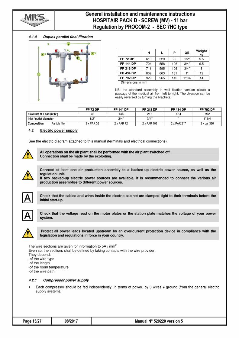
4.1.4 Duplex parallel final filtration
FP 72 DP FP 144 DP FP 218 DP FP 434 DP FP 792 DP 7��8������#����09:; �� 72 144 218 434 792
� ���'������/��0���� 1/2" 3/4" 3/4" " 1"1/4
�0$�.���� ������������� ��� ��� ��� ��� ��� ���� ��� ���� ��������
4.2 Electric power supply
See the electric diagram attached to this manual (terminals and electrical connections).
All operations on the air plant shall be performed with the air plant switched off. Connection shall be made by the exploiting.
Connect at least one air production assembly to a backed-up electric power source, as well as the regulation unit. If two backed-up electric power sources are available, it is recommended to connect the various air production assemblies to different power sources.
Check that the cables and wires inside the electric cabinet are clamped tight to their terminals before the initial start-up.
Check that the voltage read on the motor plates or the station plate matches the voltage of your power system.
Protect all power leads located upstream by an over-current protection device in compliance with the legislation and regulations in force in your country.
The wire sections are given for information to 5A / mm
2.
Even so, the sections shall be defined by taking contacts with the wire provider. They depend: -of the wire type -of the length -of the room temperature -of the wire path
4.2.1 Compressor power supply
• Each compressor should be fed independently, in terms of power, by 3 wires + ground (from the general electric supply system).
H L P ØE Weight kg
FP 72 DP 610 529 92 1/2" 5.5
FP 144 DP 704 558 106 3/4" 6.5
FP 218 DP 711 595 106 3/4" 8
FP 434 DP 809 663 131 1" 12
FP 792 DP 929 965 142 1"1/4 14
Dimensions in mm NB: the standard assembly in wall fixation version allows a passage of the medical air from left to right. The direction can be easily reversed by turning the brackets.
-� ����� .�������� � /0�� �� � 1�� .���1��� .������������� �������� �������������� �!����� " ��#��!$� �
�� ���(+,"%""%2��.�� , %&'"%�# �����4'"#
�
Protections in Amperes
Screw compressor 3-ph 400V 50Hz MVX2 MVX3 MVX4 MVX5 MVA8 MVB12 MVB16 MVC19 MVC23
Power (kW) for each compressor 2.2 3 4 5.5 7.5 11 15 22 22
Strength of current (A) 4.9 6.4 8.1 10.8 15 24 30 42 43
Wire cross section (mm²) for each compressor 2.5 2.5 2.5 2.5 4 6 10 16 16
Protection to install (A) 10 16 16 16 25 32 40 63 63
4.2.2 PROCOM-2 power supply
Feed the PROCOM-2 electrical box with 1-ph 230V – 50/60Hz via 2 x 1.5 mm² + ground cable. NB: Connect the PROCOM-2 alarm synthesis (AL1 / AL2) to a visual and/or audible alarm on the control unit
4.2.3 Connection between compressor and PROCOM-2 electrical box
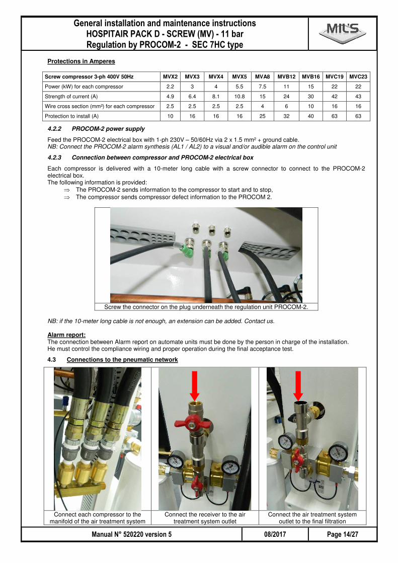
Each compressor is delivered with a 10-meter long cable with a screw connector to connect to the PROCOM-2 electrical box. The following information is provided:
⇒ The PROCOM-2 sends information to the compressor to start and to stop, ⇒ The compressor sends compressor defect information to the PROCOM 2.
Screw the connector on the plug underneath the regulation unit PROCOM-2.
NB: if the 10-meter long cable is not enough, an extension can be added. Contact us. Alarm report: The connection between Alarm report on automate units must be done by the person in charge of the installation. He must control the compliance wiring and proper operation during the final acceptance test.
4.3 Connections to the pneumatic network
Connect each compressor to the
manifold of the air treatment system Connect the receiver to the air
treatment system outlet Connect the air treatment system
outlet to the final filtration
� �
-� ����� .�������� � /0�� �� � 1�� .���1��� .������������� �������� �������������� �!����� " ��#��!$��
�����,'"# %&'"%�# �� ���(+,"%""%2��.�� ,
�
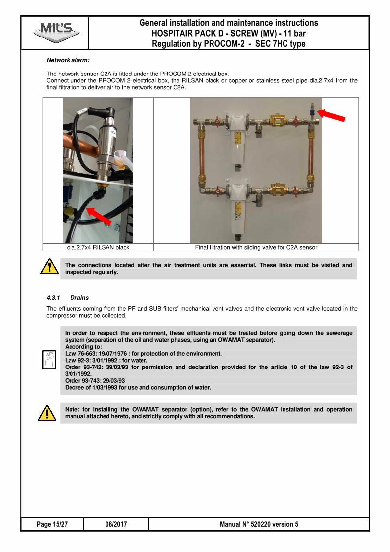
Network alarm: The network sensor C2A is fitted under the PROCOM 2 electrical box. Connect under the PROCOM 2 electrical box, the RILSAN black or copper or stainless steel pipe dia.2.7x4 from the final filtration to deliver air to the network sensor C2A.
dia.2.7x4 RILSAN black Final filtration with sliding valve for C2A sensor
The connections located after the air treatment units are essential. These links must be visited and inspected regularly.
4.3.1 Drains
The effluents coming from the PF and SUB filters’ mechanical vent valves and the electronic vent valve located in the compressor must be collected.
In order to respect the environment, these effluents must be treated before going down the sewerage system (separation of the oil and water phases, using an OWAMAT separator). According to: Law 76-663: 19/07/1976 : for protection of the environment. Law 92-3: 3/01/1992 : for water. Order 93-742: 39/03/93 for permission and declaration provided for the article 10 of the law 92-3 of 3/01/1992. Order 93-743: 29/03/93 Decree of 1/03/1993 for use and consumption of water.
Note: for installing the OWAMAT separator (option), refer to the OWAMAT installation and operation manual attached hereto, and strictly comply with all recommendations.
-� ����� .�������� � /0�� �� � 1�� .���1��� .������������� �������� �������������� �!����� " ��#��!$� �
�� ���(+,"%""%2��.�� , %&'"%�# �����5'"#
�
SECTION 5 CONNECTIONS
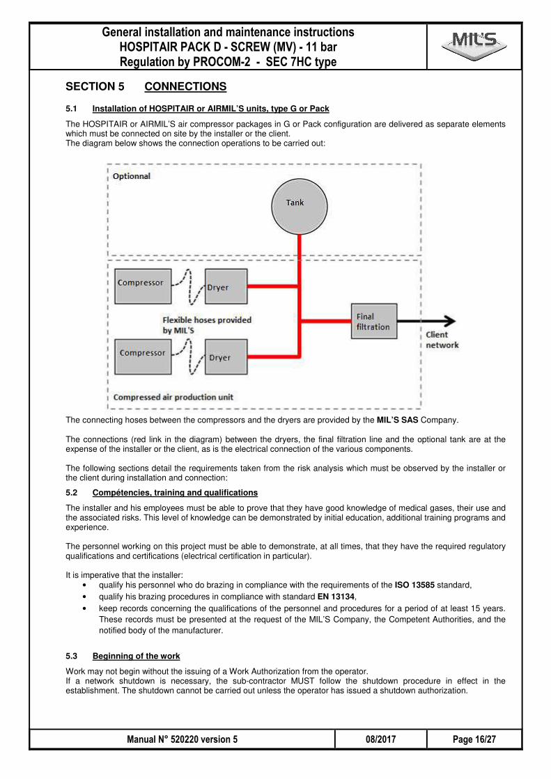
5.1 Installation of HOSPITAIR or AIRMIL’S units, type G or Pack
The HOSPITAIR or AIRMIL’S air compressor packages in G or Pack configuration are delivered as separate elements which must be connected on site by the installer or the client. The diagram below shows the connection operations to be carried out:
The connecting hoses between the compressors and the dryers are provided by the MIL’S SAS Company. The connections (red link in the diagram) between the dryers, the final filtration line and the optional tank are at the expense of the installer or the client, as is the electrical connection of the various components. The following sections detail the requirements taken from the risk analysis which must be observed by the installer or the client during installation and connection:
5.2 Compétencies, training and qualifications
The installer and his employees must be able to prove that they have good knowledge of medical gases, their use and the associated risks. This level of knowledge can be demonstrated by initial education, additional training programs and experience. The personnel working on this project must be able to demonstrate, at all times, that they have the required regulatory qualifications and certifications (electrical certification in particular). It is imperative that the installer:
• qualify his personnel who do brazing in compliance with the requirements of the ISO 13585 standard,
• qualify his brazing procedures in compliance with standard EN 13134,
• keep records concerning the qualifications of the personnel and procedures for a period of at least 15 years.
These records must be presented at the request of the MIL’S Company, the Competent Authorities, and the
notified body of the manufacturer.
5.3 Beginning of the work
Work may not begin without the issuing of a Work Authorization from the operator. If a network shutdown is necessary, the sub-contractor MUST follow the shutdown procedure in effect in the establishment. The shutdown cannot be carried out unless the operator has issued a shutdown authorization.
� �
-� ����� .�������� � /0�� �� � 1�� .���1��� .������������� �������� �������������� �!����� " ��#��!$��
�����#'"# %&'"%�# �� ���(+,"%""%2��.�� ,
�
The sub-contractor must comply with the requirements of the health care establishment in terms of hygiene and cleanliness, particularly during work in sterile areas and/or areas occupied by patients. Special attention will be paid to the risk of bio-contamination of equipment and components. Before the installation of each component, the sub-contractor must verify its state of integrity, its level of cleanliness and, if applicable, the best by or expiry date. All components which have damaged packaging must be discarded. The sub-contractor must be particularly vigilant, during work near sources of production, regarding the possible automatic restarting of rotating machines (remote-controlled starting). For work on electrical control panels, lock-out systems must be used. All of the components used must be compatible with oxygen and delivered clean, in compliance with the requirements of standard NF EN ISO 15001.
5.4 Optionnal tank
If the operator takes charge of supplying the storage tank, it must be adapted to the nominal working pressure of the
facility and must bear the CE marking in compliance with directive 2014/68/UE (equipment under pressure) or
2014/29/UE (simple pressure vessels).
The tank must be equipped with:
• one or several sectional valves,
• a CE marked safety valve in compliance with directive 2014/68/UE (equipment under pressure),
• a manometer,
• a drain valve.
5.5 Pipes, flexible hoses and fittings
The rigid pipes must be made of copper in compliance with standard NF EN 13348. The pipe diameters must be identical to the input / outlet diameters of the elements to be connected. The piping, of a diameter less than 32 mm (diameter 1’’ ¼ maximum) is, in the meaning of directive 2014/68/UE, classified in the meaning of article 4.3. The fittings used to connect the copper pipes must be compliant with EN 1254-1 and EN 1254-4. If low pressure connecting hoses are used, they must be in compliance with standard NF EN ISO 5359. All of the components used must be delivered clean, protected from all contamination before and during the installation. Furthermore, the components and materials must be able to withstand 1.5 times the operating pressure for the compressed gases. Proof of the maintaining of the pressure of the piping and components used must be presented by the installer upon request from the MIL’S Company, the Competent Authorities or the notified body of the manufacturer. The storage and handling conditions must ensure the preservation of the product and of its level of cleanliness, until the final assembly. The cutting of piping intended for the distribution of compressed medical fluids must be EXCLUSIVELY done with a pipe cutter in order to limit the risk of introduction of shavings or particles. The installation of the piping must be done according to Professional Standards and must meet the applicable requirements of section § 11.1 of standard NF EN ISO 7396-1. The pipe supports must be compliant with the requirements of section § 11.2 of standard NF EN ISO 7396-1 All of the components of the network must be connected to a ground connector in compliance with the regulations in effect. The pipes must be protected against all physical damage.
-� ����� .�������� � /0�� �� � 1�� .���1��� .������������� �������� �������������� �!����� " ��#��!$� �
�� ���(+,"%""%2��.�� , %&'"%�# �����&'"#
�
5.6 Brazing of piping
With the exception of the mechanical fittings used for certain components, all of the metallic fittings must be brazed or welded. If a filler metal is used, its temperature in the liquid state must not be less than 600 °C. T he filler metals must be nominally free of cadmium. If silver alloys are used, they must be compliant with ISO 17672. During the brazing or welding of the pipe fittings, the interior of the pipe must be constantly purged with a protective gas in order to limit the risk of introduction of shavings or particles. The sub-contractor cannot carry out brazing operations unless he has a fire permit issued by the health care establishment.
5.7 Verifications during and after the installation of the pipes
Self-verifications must be carried out during the installation, particularly a visual verification of the brazing in order to detect:
• the absence of flux during the brazing operation,
• any deterioration of the base metal due to overheating,
• the absence of filler metal at the joint,
• the absence of run-out or surplus filler metal,
The piping and components of the network which provide the link between the various components of the production unit must be subjected to a tightness test at 1.5 times the operating pressure (identical to the pressure of the compressor). The table below indicates the pressure to be applied for this test:
Compressor pressure (bar) Test pressure (bar)
11 16.5
15 22.5
The results of the verifications must be recorded and saved. The entire facility must undergo a final verification before commissioning. Standard NF EN ISO 7396-1 applicable to medical gas distribution systems details the tests to be carried out. The results of the verifications must be recorded and kept.
5.8 Identification and traceability
There must be traceability for the following elements. • Sources of production,
• Storage tank,
• Safety valves installed on the network,
• Valves (if they bear a serial or batch number).
The sub-contractor MUST indicate the serial or batch numbers of the above components on the self-verification report. The sub-contractor must label the distribution system and the valves at risk in compliance with the standards and regulations (ruling of December 10, 2004 in particular) in effect.
� �
-� ����� .�������� � /0�� �� � 1�� .���1��� .������������� �������� �������������� �!����� " ��#��!$��
�����6'"# %&'"%�# �� ���(+,"%""%2��.�� ,
�
SECTION 6 RUNNING OPERATION
Screw compressor which will be stored for more than 6 months must be drained; air and oil filters and oil separator must be replaced.
In the contrary case, the filters tend to dry and create an abnormal pressure loss causing a pressure higher than the valve opening pressure of the separator tank of the compressor and a very strong oil mist can escape. Oil can degrade and more not provide its function.
6.1 First step
• Check the oil level of compressors.
• Before starting the equipment, first read all the running operation and maintenance manuals (screw compressor, ADSORMIL'S air dryer, PROCOM-2).
• Set the On/Off switch to O (Off) on all compressors.
• Mask hygrometry on the PROCOM-2: Hygrometry is masked during 24 hours on the PROCOM-2.
6.2 Switching on
Warning: Upon first start-up, or if a major incident has occurred on the network and the network had to be brought back to atmospheric pressure, during the first moments of operation, the quality of the air will not be in compliance with the European monograph (past: NFS 90 155 standard), as the ambient air which was present in the whole system has to be eliminated. Therefore the pressure reducing valve outlet must be shut off, pressure must be increased, the compressors must be stopped, and the system must be vented until a residual pressure of 2 bar is obtained in the receiver (this procedure is described below). Note: during the first commissioning procedure, or after an intervention on the system, these operations will not solve the hygrometry problem.
Each screw compressor is equipped with a phase controller indicates phases are in correct position. If not, the compressor can't start. • Shut off the network outlet valve on the final filtration. • Start the compressor A pushing the "I" key on the SIGMA CONTROL: if there is an electrical problem and fault, the
compressor stops immediately. In this case, insulate the compressor electrically and cross 2 wires at compressor motor level.
• Stop the compressor A and start compressors B and C to check the rotation direction of each compressor.
• Restart all compressors to allow the pressure to go up to maximum level. • Check the links for leaks. • Cut off all compressors and vent the receiver to 2 bar. • Restart all the compressors and open the network outlet valve gradually.
• To check the regulation for correct operation: ⇒ isolate the system from the network, using the final filtration valve, ⇒ create a leak that you will control according to the intended purpose, on the receiver vent valve,
⇒ after the check, shut off the vent valve and open the network valve. • For further information concerning the PROCOM-2 regulation mode, refer to its manual
-� ����� .�������� � /0�� �� � 1�� .���1��� .������������� �������� �������������� �!����� " ��#��!$� �
�� ���(+,"%""%2��.�� , %&'"%�# ����"%'"#
�
SECTION 7 SETTINGS
7.1 Setting pressure
Any modification to the settings should only be carried out by qualified and authorised personnel. Improper actions may cause complete system malfunction.
7.1.1 For PROCOM-2: C1A
Factory settings: Upper limit: ..................................................... 10 bar Lower limit 1st compressor: ............................... 9 bar Lower limit 2nd compressor: ........................... 8.5 bar Lower limit 3
rd compressor: .............................. 8 bar
Regulation alarm ........................................... 7.5 bar For PROCOM-2: modify values in the parameter page.
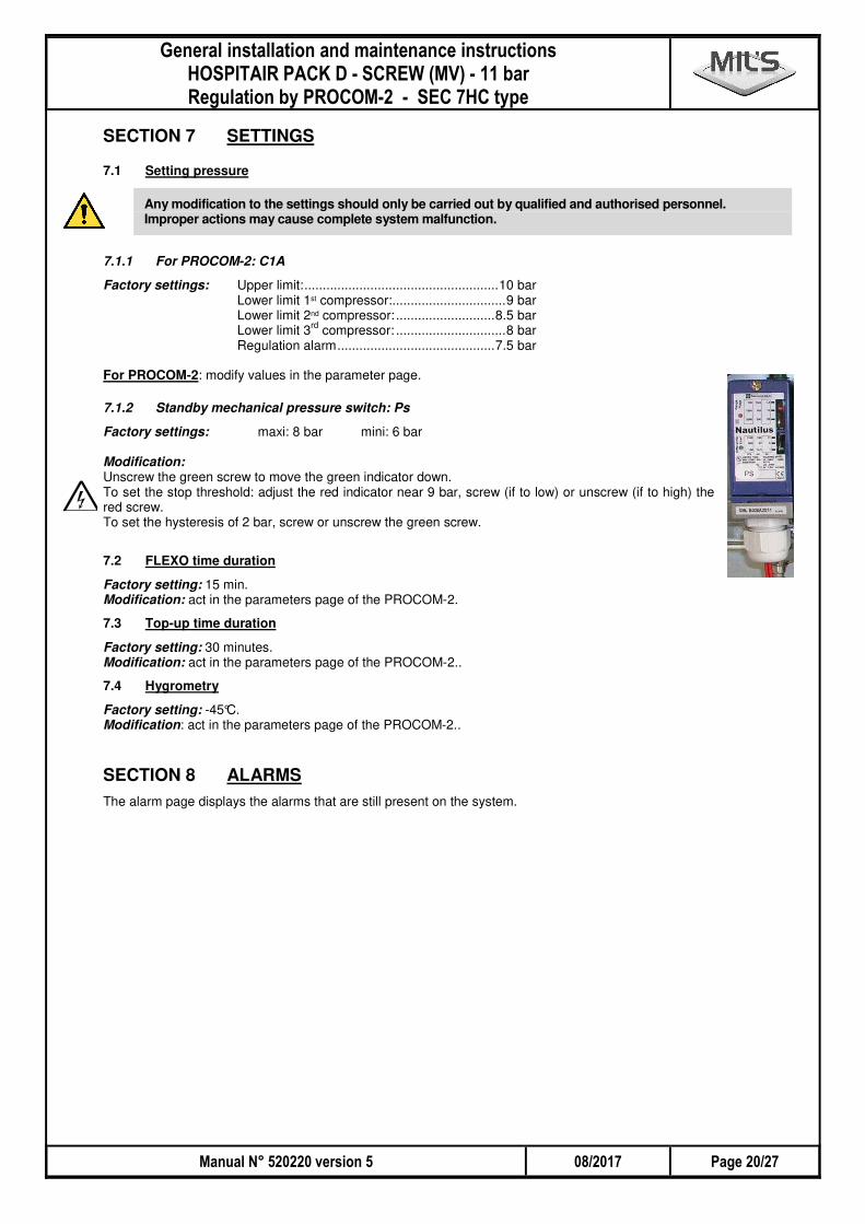
7.1.2 Standby mechanical pressure switch: Ps
Factory settings: maxi: 8 bar mini: 6 bar Modification: Unscrew the green screw to move the green indicator down. To set the stop threshold: adjust the red indicator near 9 bar, screw (if to low) or unscrew (if to high) the red screw. To set the hysteresis of 2 bar, screw or unscrew the green screw.
7.2 FLEXO time duration
Factory setting: 15 min. Modification: act in the parameters page of the PROCOM-2.
7.3 Top-up time duration
Factory setting: 30 minutes. Modification: act in the parameters page of the PROCOM-2..
7.4 Hygrometry
Factory setting: -45°C. Modification: act in the parameters page of the PROCOM-2..
SECTION 8 ALARMS The alarm page displays the alarms that are still present on the system.
� �
-� ����� .�������� � /0�� �� � 1�� .���1��� .������������� �������� �������������� �!����� " ��#��!$��
����"�'"# %&'"%�# �� ���(+,"%""%2��.�� ,
�
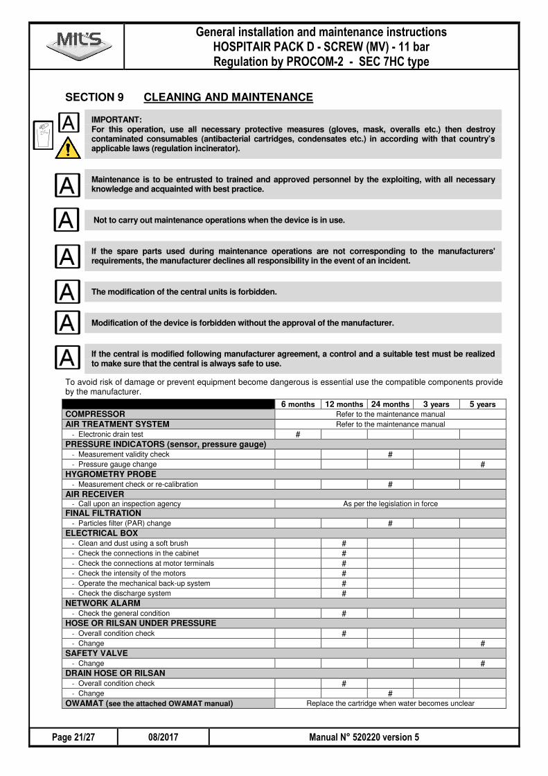
SECTION 9 CLEANING AND MAINTENANCE
IMPORTANT: For this operation, use all necessary protective measures (gloves, mask, overalls etc.) then destroy contaminated consumables (antibacterial cartridges, condensates etc.) in according with that country’s applicable laws (regulation incinerator).
Maintenance is to be entrusted to trained and approved personnel by the exploiting, with all necessary knowledge and acquainted with best practice.
Not to carry out maintenance operations when the device is in use.
If the spare parts used during maintenance operations are not corresponding to the manufacturers' requirements, the manufacturer declines all responsibility in the event of an incident.
The modification of the central units is forbidden.
Modification of the device is forbidden without the approval of the manufacturer.
If the central is modified following manufacturer agreement, a control and a suitable test must be realized to make sure that the central is always safe to use.
To avoid risk of damage or prevent equipment become dangerous is essential use the compatible components provide by the manufacturer.
6 months 12 months 24 months 3 years 5 years COMPRESSOR Refer to the maintenance manual
AIR TREATMENT SYSTEM Refer to the maintenance manual
- Electronic drain test # PRESSURE INDICATORS (sensor, pressure gauge)
- Measurement validity check # - Pressure gauge change #
HYGROMETRY PROBE - Measurement check or re-calibration #
AIR RECEIVER - Call upon an inspection agency As per the legislation in force
FINAL FILTRATION - Particles filter (PAR) change #
ELECTRICAL BOX - Clean and dust using a soft brush # - Check the connections in the cabinet # - Check the connections at motor terminals # - Check the intensity of the motors # - Operate the mechanical back-up system # - Check the discharge system #
NETWORK ALARM - Check the general condition #
HOSE OR RILSAN UNDER PRESSURE - Overall condition check # - Change #
SAFETY VALVE - Change #
DRAIN HOSE OR RILSAN - Overall condition check # - Change #
OWAMAT (see the attached OWAMAT manual) Replace the cartridge when water becomes unclear
-� ����� .�������� � /0�� �� � 1�� .���1��� .������������� �������� �������������� �!����� " ��#��!$� �
�� ���(+,"%""%2��.�� , %&'"%�# ����""'"#
�
Note: the maintenance periodicities above are given for reference only and may be increased as required. Note: maintenance tables are available for the compressor, the air treatment unit and the pressure reducing valve outlet.
9.1 Electronic vent valve test
A test button is provided at the top of the valve for manual venting. For more information, see the attached manual (BEKOMAT 12).
9.2 Pressure indicator
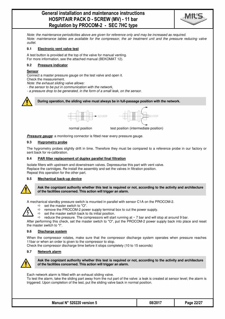
Sensor Connect a master pressure gauge on the test valve and open it. Check the measurement. Note: the exhaust sliding valve allows: - the sensor to be put in communication with the network, - a pressure drop to be generated, in the form of a small leak, on the sensor.
During operation, the sliding valve must always be in full-passage position with the network.
normal position test position (intermediate position) Pressure gauge: a monitoring connector is fitted near every pressure gauge.
9.3 Hygrometry probe
The hygrometry probes slightly drift in time. Therefore they must be compared to a reference probe in our factory or sent back for re-calibration.
9.4 PAR filter replacement of duplex parallel final filtration
Isolate filters with upstream and downstream valves. Depressurise this part with vent valve. Replace the cartridges. Re-install the assembly and set the valves in filtration position. Repeat this operation for the other part.
9.5 Mechanical back-up device
Ask the cognizant authority whether this test is required or not, according to the activity and architecture of the facilities concerned. This action will trigger an alarm.
A mechanical standby pressure switch is mounted in parallel with sensor C1A on the PROCOM-2.
� set the master switch to "O". � remove the PROCOM-2 power supply terminal box to cut the power supply. � set the master switch back to its initial position. � reduce the pressure. The compressors will start running at ~ 7 bar and will stop at around 9 bar.
After performing this check, set the master switch to "O", put the PROCOM-2 power supply back into place and reset the master switch to "I".
9.6 Discharge system
When the compressor rotates, make sure that the compressor discharge system operates when pressure reaches 11bar or when an order is given to the compressor to stop. Check the compressor discharge time before it stops completely (10 to 15 seconds)
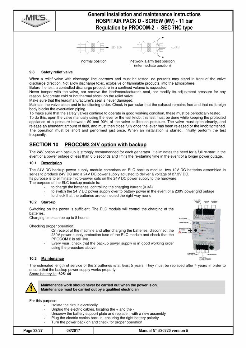
9.7 Network alarm
Ask the cognizant authority whether this test is required or not, according to the activity and architecture of the facilities concerned. This action will trigger an alarm.
Each network alarm is fitted with an exhaust sliding valve. To test the alarm, take the sliding part away from the nut part of the valve: a leak is created at sensor level; the alarm is triggered. Upon completion of the test, put the sliding valve back in normal position.
� �
-� ����� .�������� � /0�� �� � 1�� .���1��� .������������� �������� �������������� �!����� " ��#��!$��
����"3'"# %&'"%�# �� ���(+,"%""%2��.�� ,
�
normal position network alarm test position (intermediate position)
9.8 Safety relief valve
When a relief valve with discharge line operates and must be tested, no persons may stand in front of the valve discharge direction. Not allow discharge toxic, explosive or flammable products, into the atmosphere. Before the test, a controlled discharge procedure in a confined volume is requested. Never tamper with the valve, nor remove the lead/manufacturer's seal, nor modify its adjustment pressure for any reason. Not create cold or hot thermal shock on the relief valve. Make sure that the lead/manufacturer's seal is never damaged. Maintain the valve clean and in functioning order. Check in particular that the exhaust remains free and that no foreign body blocks the evacuation piping. To make sure that the safety valves continue to operate in good working condition, these must be periodically tested. To do this, open the valve manually using the lever or the test knob; this test must be done while keeping the protected appliance at a pressure between 80 and 90% of the valve calibration pressure. The valve must open cleanly, and release an abundant amount of fluid, and must then close fully once the lever has been released or the knob tightened. The operation must be short and performed just once. When an installation is started, initially perform the test frequently.
SECTION 10 PROCOM3 24V option with backup The 24V option with backup is strongly recommended for each generator. It eliminates the need for a full re-start in the event of a power outage of less than 0.5 seconds and limits the re-starting time in the event of a longer power outage.
10.1 Description
The 24V DC backup power supply module comprises an ELC backup module, two 12V DC batteries assembled in series to produce 24V DC and a 24V DC power supply adjusted to deliver a voltage of 27.3V DC. Its purpose is to eliminate micro-power cuts on the 24V DC power supply to the hardware. The purpose of the ELC backup module is:
- to charge the batteries, controlling the charging current (0.3A) - to switch the 24 V DC power supply over to battery power in the event of a 230V power grid outage - to check that the batteries are connected the right way round
10.2 Start-up
Switching on the power is sufficient. The ELC module will control the charging of the batteries. Charging time can be up to 8 hours. Checking proper operation:
- On receipt of the machine and after charging the batteries, disconnect the 230V power supply protection fuse of the ELC module and check that the PROCOM 2 is still live.
- Every year, check that the backup power supply is in good working order using the procedure above
10.3 Maintenance
The estimated length of service of the 2 batteries is at least 5 years. They must be replaced after 4 years in order to ensure that the backup power supply works properly. Spare battery kit: 625144
Maintenance work should never be carried out when the power is on. Maintenance must be carried out by a qualified electrician
For this purpose:
- Isolate the circuit electrically - Unplug the electric cables, locating the + and the - - Unscrew the battery support plate and replace it with a new assembly - Plug the electric cables back in, ensuring the right battery polarity - Turn the power back on and check for proper operation
-� ����� .�������� � /0�� �� � 1�� .���1��� .������������� �������� �������������� �!����� " ��#��!$� �
�� ���(+,"%""%2��.�� , %&'"%�# ����"4'"#
�
Dispose of the batteries in accordance with the regulations in the country.
SECTION 11 TEST PRESSURE Each equipment under pressure was tested individually by its respective manufacturer. The connection of the equipment is carried out by assembly without welding.
SECTION 12 PROTECTION AGAINST OVERPRESSURE The various modules constituting the compressed air unit, object of this technical manual, are protected by relief valves as indicated in the table hereafter:
Component Pressure setting (bar) Location of the safety relief valve
Compressor 13 bar In the compressor
Dryer --- Protected by the safety relief valve of the compressor
Receiver 11 bar On the receiver
SECTION 13 TRAINING In order to ensure perfect aptitude in the use of the oxygen concentrator, the MIL'S Company offers its own training for the use of this equipment. It is intended for users and technical personnel working on or near the air production plant.
SECTION 14 CLEANING
14.1 Units cleaning
Do not use corrosive product
If the units system requires cleaning, use a soap solution and a clean cloth. Then wipe well with a dry cloth. For disinfection, use swabs soaked in a disinfectant solution. Frequency: as required.
� �
-� ����� .�������� � /0�� �� � 1�� .���1��� .������������� �������� �������������� �!����� " ��#��!$��
����",'"# %&'"%�# �� ���(+,"%""%2��.�� ,
�
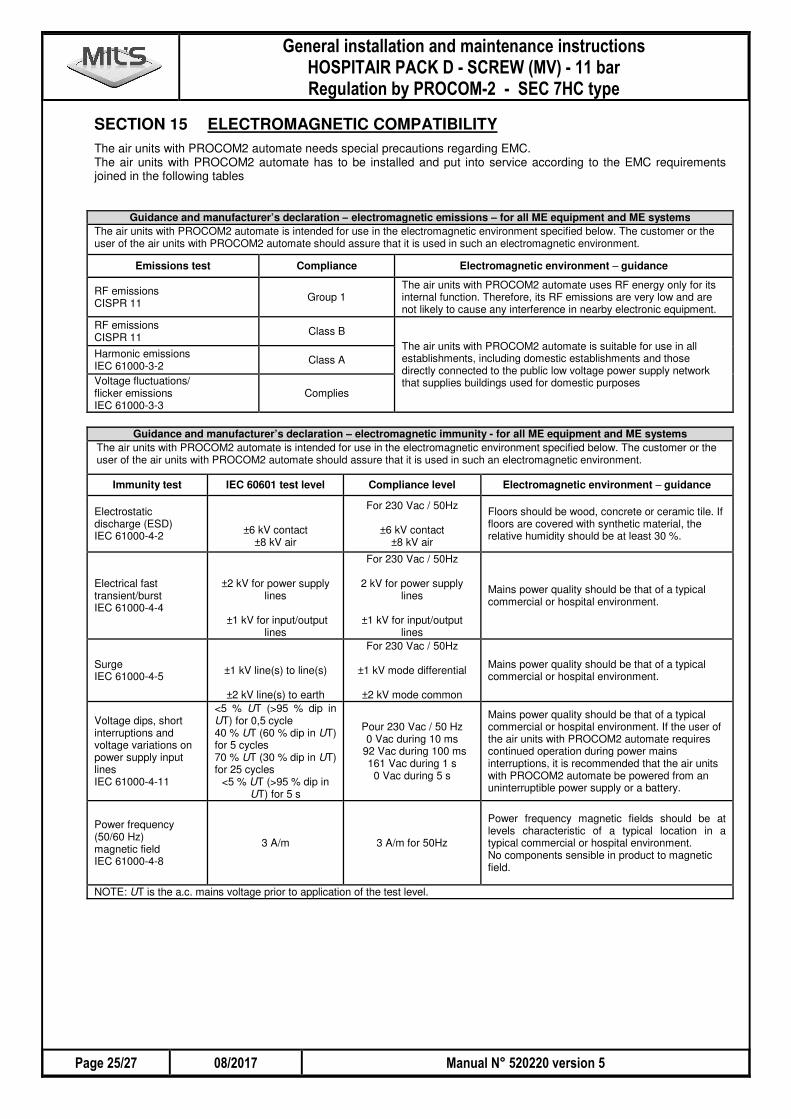
SECTION 15 ELECTROMAGNETIC COMPATIBILITY The air units with PROCOM2 automate needs special precautions regarding EMC. The air units with PROCOM2 automate has to be installed and put into service according to the EMC requirements joined in the following tables
Guidance and manufacturer’s declaration – electromagnetic emissions – for all ME equipment and ME systems The air units with PROCOM2 automate is intended for use in the electromagnetic environment specified below. The customer or the user of the air units with PROCOM2 automate should assure that it is used in such an electromagnetic environment.
Emissions test Compliance Electromagnetic environment – guidance
RF emissions CISPR 11
Group 1 The air units with PROCOM2 automate uses RF energy only for its internal function. Therefore, its RF emissions are very low and are not likely to cause any interference in nearby electronic equipment.
RF emissions CISPR 11
Class B
The air units with PROCOM2 automate is suitable for use in all establishments, including domestic establishments and those directly connected to the public low voltage power supply network that supplies buildings used for domestic purposes
Harmonic emissions IEC 61000-3-2
Class A
Voltage fluctuations/ flicker emissions IEC 61000-3-3
Complies
Guidance and manufacturer’s declaration – electromagnetic immunity - for all ME equipment and ME systems
The air units with PROCOM2 automate is intended for use in the electromagnetic environment specified below. The customer or the user of the air units with PROCOM2 automate should assure that it is used in such an electromagnetic environment.
Immunity test IEC 60601 test level Compliance level Electromagnetic environment – guidance
Electrostatic discharge (ESD) IEC 61000-4-2
±6 kV contact ±8 kV air
For 230 Vac / 50Hz
±6 kV contact ±8 kV air
Floors should be wood, concrete or ceramic tile. If floors are covered with synthetic material, the relative humidity should be at least 30 %.
Electrical fast transient/burst IEC 61000-4-4
±2 kV for power supply lines
±1 kV for input/output
lines
For 230 Vac / 50Hz
2 kV for power supply lines
±1 kV for input/output
lines
Mains power quality should be that of a typical commercial or hospital environment.
Surge IEC 61000-4-5
±1 kV line(s) to line(s)
±2 kV line(s) to earth
For 230 Vac / 50Hz
±1 kV mode differential
±2 kV mode common
Mains power quality should be that of a typical commercial or hospital environment.
Voltage dips, short interruptions and voltage variations on power supply input lines IEC 61000-4-11
<5 % UT (>95 % dip in UT) for 0,5 cycle 40 % UT (60 % dip in UT) for 5 cycles 70 % UT (30 % dip in UT) for 25 cycles
<5 % UT (>95 % dip in UT) for 5 s
Pour 230 Vac / 50 Hz 0 Vac during 10 ms
92 Vac during 100 ms 161 Vac during 1 s 0 Vac during 5 s
Mains power quality should be that of a typical commercial or hospital environment. If the user of the air units with PROCOM2 automate requires continued operation during power mains interruptions, it is recommended that the air units with PROCOM2 automate be powered from an uninterruptible power supply or a battery.
Power frequency (50/60 Hz) magnetic field IEC 61000-4-8
3 A/m 3 A/m for 50Hz
Power frequency magnetic fields should be at levels characteristic of a typical location in a typical commercial or hospital environment. No components sensible in product to magnetic field.
NOTE: UT is the a.c. mains voltage prior to application of the test level.
-� ����� .�������� � /0�� �� � 1�� .���1��� .������������� �������� �������������� �!����� " ��#��!$� �
�� ���(+,"%""%2��.�� , %&'"%�# ����"5'"#
�
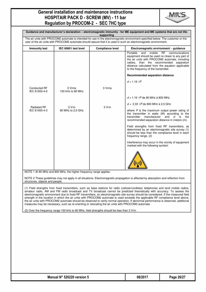
Guidance and manufacturer’s declaration – electromagnetic immunity - for ME equipment and ME systems that are not life-supporting
The air units with PROCOM2 automate is intended for use in the electromagnetic environment specified below. The customer or the user of the air units with PROCOM2 automate should assure that it is used in such an electromagnetic environment.
Immunity test IEC 60601 test level Compliance level Electromagnetic environment – guidance
Conducted RF IEC 61000-4-6
Radiated RF IEC 61000-4-3
3 Vrms 150 kHz to 80 MHz
3 V/m 80 MHz to 2,5 GHz
3 Vrms
3 V/m
Portable and mobile RF communications equipment should be used no closer to any part of the air units with PROCOM2 automate, including cables, than the recommended separation distance calculated from the equation applicable to the frequency of the transmitter. Recommended separation distance d = 1.16 √P d = 1.16 √P de 80 MHz à 800 MHz d = 2.33 √P de 800 MHz à 2,5 GHz where P is the maximum output power rating of the transmitter in watts (W) according to the transmitter manufacturer and d is the recommended separation distance in meters (m). Field strengths from fixed RF transmitters, as determined by an electromagnetic site survey (1) should be less than the compliance level in each frequency range. (2) Interference may occur in the vicinity of equipment marked with the following symbol:
NOTE 1 At 80 MHz and 800 MHz, the higher frequency range applies. NOTE 2 These guidelines may not apply in all situations. Electromagnetic propagation is affected by absorption and reflection from structures, objects and people.
(1) Field strengths from fixed transmitters, such as base stations for radio (cellular/cordless) telephones and land mobile radios, amateur radio, AM and FM radio broadcast and TV broadcast cannot be predicted theoretically with accuracy. To assess the electromagnetic environment due to fixed RF transmitters, an electromagnetic site survey should be considered. If the measured field strength in the location in which the air units with PROCOM2 automate is used exceeds the applicable RF compliance level above, the air units with PROCOM2 automate should be observed to verify normal operation. If abnormal performance is observed, additional measures may be necessary, such as re-orienting or relocating the air units with PROCOM2 automate. (2) Over the frequency range 150 kHz to 80 MHz, field strengths should be less than 3 V/m.
� �
-� ����� .�������� � /0�� �� � 1�� .���1��� .������������� �������� �������������� �!����� " ��#��!$��
����"#'"# %&'"%�# �� ���(+,"%""%2��.�� ,
�
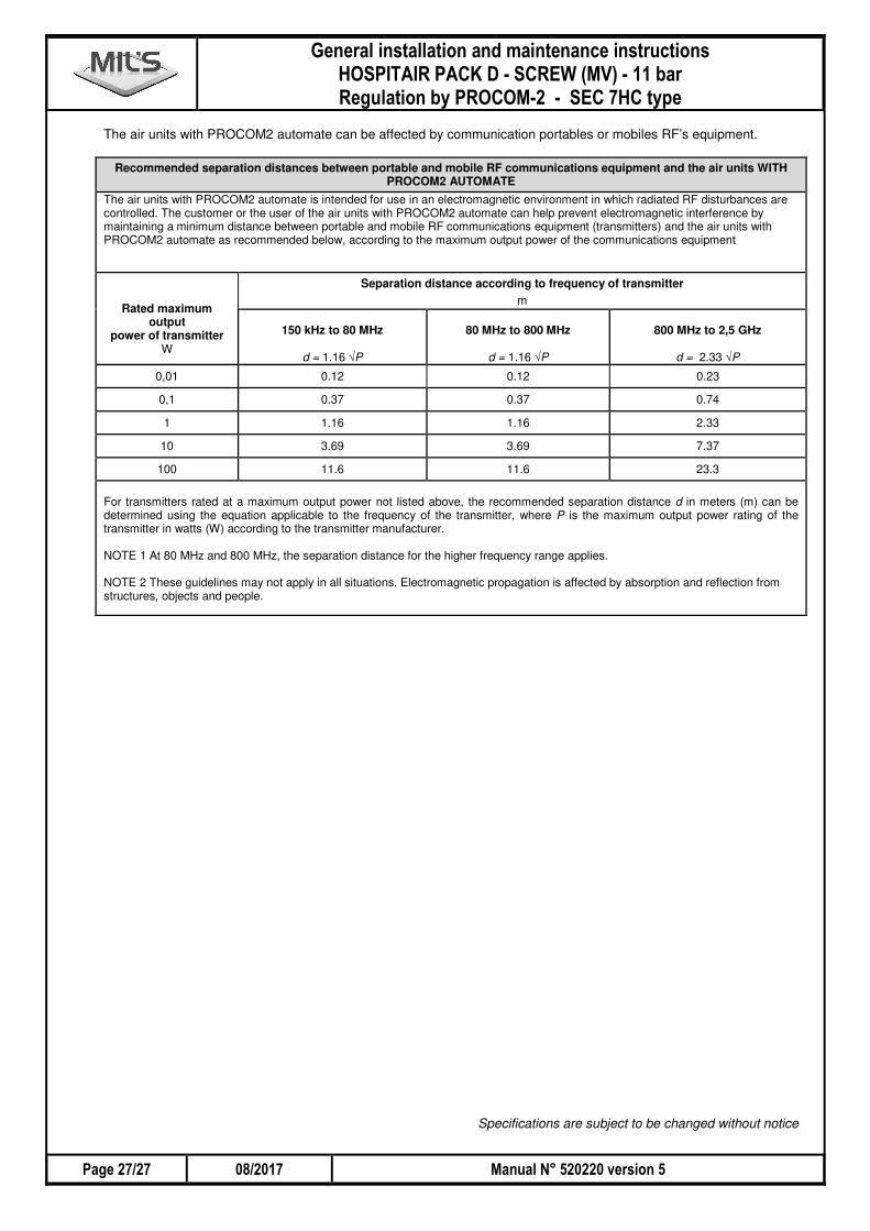
The air units with PROCOM2 automate can be affected by communication portables or mobiles RF’s equipment.
Recommended separation distances between portable and mobile RF communications equipment and the air units WITH PROCOM2 AUTOMATE
The air units with PROCOM2 automate is intended for use in an electromagnetic environment in which radiated RF disturbances are controlled. The customer or the user of the air units with PROCOM2 automate can help prevent electromagnetic interference by maintaining a minimum distance between portable and mobile RF communications equipment (transmitters) and the air units with PROCOM2 automate as recommended below, according to the maximum output power of the communications equipment
Separation distance according to frequency of transmitter
Rated maximum output
power of transmitter W
m
150 kHz to 80 MHz
d = 1.16 √P
80 MHz to 800 MHz
d = 1.16 √P
800 MHz to 2,5 GHz
d = 2.33 √P
0,01 0.12 0.12 0.23
0,1 0.37 0.37 0.74
1 1.16 1.16 2.33
10 3.69 3.69 7.37
100 11.6 11.6 23.3
For transmitters rated at a maximum output power not listed above, the recommended separation distance d in meters (m) can be determined using the equation applicable to the frequency of the transmitter, where P is the maximum output power rating of the transmitter in watts (W) according to the transmitter manufacturer. NOTE 1 At 80 MHz and 800 MHz, the separation distance for the higher frequency range applies. NOTE 2 These guidelines may not apply in all situations. Electromagnetic propagation is affected by absorption and reflection from structures, objects and people.
Specifications are subject to be changed without notice

__________________________________________________________________________________________
__________________________________________________________________________________________
__________________________________________________________________________________________
__________________________________________________________________________________________
__________________________________________________________________________________________
__________________________________________________________________________________________
__________________________________________________________________________________________
__________________________________________________________________________________________
__________________________________________________________________________________________
__________________________________________________________________________________________
__________________________________________________________________________________________
__________________________________________________________________________________________
__________________________________________________________________________________________
__________________________________________________________________________________________
__________________________________________________________________________________________
__________________________________________________________________________________________
__________________________________________________________________________________________
__________________________________________________________________________________________
__________________________________________________________________________________________
__________________________________________________________________________________________
__________________________________________________________________________________________
__________________________________________________________________________________________
__________________________________________________________________________________________
__________________________________________________________________________________________
__________________________________________________________________________________________
__________________________________________________________________________________________
__________________________________________________________________________________________
__________________________________________________________________________________________
__________________________________________________________________________________________
__________________________________________________________________________________________

__________________________________________________________________________________________
__________________________________________________________________________________________
__________________________________________________________________________________________
__________________________________________________________________________________________
__________________________________________________________________________________________
__________________________________________________________________________________________
__________________________________________________________________________________________
__________________________________________________________________________________________
__________________________________________________________________________________________
__________________________________________________________________________________________
__________________________________________________________________________________________
__________________________________________________________________________________________
__________________________________________________________________________________________
__________________________________________________________________________________________
__________________________________________________________________________________________
__________________________________________________________________________________________
__________________________________________________________________________________________
__________________________________________________________________________________________
__________________________________________________________________________________________
__________________________________________________________________________________________
__________________________________________________________________________________________
__________________________________________________________________________________________
__________________________________________________________________________________________
__________________________________________________________________________________________
__________________________________________________________________________________________
__________________________________________________________________________________________
__________________________________________________________________________________________
__________________________________________________________________________________________
__________________________________________________________________________________________
__________________________________________________________________________________________

�
�

www.mils.fr
Plaque de caractéristiques / Specification plate