Embed Size (px)
Citation preview

COMPRESSED AIRTREATMENT
COMPRESSOR SYSTEMS MADE IN GERMANY

ALMiGtreatment products
ALMiGtreatment products2 3
ALMIG COMPRESSED AIR TREATMENT
+ Generation and treatment: Everything from a single source and perfectly matched
+ ALMiG covers the entire range of compressed air treatment products.
+ ALMiG can provide the right kind of compressed air treatment product for every requirement profile.
p. 4
Highly versatileFILTERS AFP, AFM, AFS, AFC
p. 6
Efficient pre-separation of condensateAS CYCLONE SEPARATOR
p. 12
Reliable and robustREFRIGERATION DRYER ALM
p. 14
Energy-saving compressed air dryingREFRIGERATION DRYER ALM-E
p. 16
Compact and space-savingREFRIGERATION DRYER ADD
p. 20
Very efficient at high performance levelsADSORPTION DRYER ALM-WD
p. 22
For oil-free & taste-neutral compressed airACTIVE CARBON ADSORBER ALM-AC
p. 10
For oil-free condensateOIL/WATER SEPARATOR ALM-OWS
p. 8
Reliable condensate drainCONDENSATE DRAIN ALM-D
p. 18
For pressure dew points of down to -70°CADSORPTION DRYER ALM-CD / ALM-CCD

+ Heavy-duty filter for clean and dry compressed air
+ Three-part housing for simple replacement of filter elements
+ Available as standard or premium version
ALMiGtreatment products
ALMiGtreatment products4 5
AFP, AFM, AFS, AFC FILTERS
Extremely lightaluminium housing
Heavy-duty filter element
Compressed air filters guarantee clean compressed air to satisfy very stringent requirements. They can be used in a multitude of applications - wherever compressed air is required clean, dry or free of oil aerosols. It's a huge undertaking, especially when you consider the fact that more than two billion particles and liquid mole-cules can be present in 1 m3 of compressed air at a com-pression end pressure of 10 bar.This is an undertaking to which the ALMiG heavy-duty filters are perfectly suited.
Equipment features:• Standard version including differential pressure
indicator and float drain• Premium version including
• differential pressure gauge to display the most cost-effective time to replace the filter element
• electronically controlled condensate drain to dis-charge condensate without any loss of compressed air
• Three-part housing with bayonet lock for simple replacement and installation of the filter elements• Extremely light aluminium housing with threaded con-
nection for volume flows of 30 - 3300 m3/h• Alternatively, as of volume flows of 2760 - 13750 m3/h, steel housing with flange connection
All details relate to 1 bar (abs), 20°C, 70% RH; 1 Aluminium housing with threaded connection including float drain and differential pressure indicator2 Aluminium housing with threaded connection including electronically controlled condensate drain and differential pressure gauge, operating pressure: 16 bar., operating temp.: min. +1 °C, max. +100 °C (60 °C)
All details relate to 1 bar (abs), 20 °C, 70% RH.1Steel housing with flange connection including float drain and differential pressure indicator2 Steel housing with flange connection including electronically controlled condensate drain and differential pressure gauge, operating pressure: 12 bar, operating temp.: min. +1 °C, max. +66 °C
The optimum filter for every requirement
Filter type Type Particle sizeResidual oil con-
tent1 Residual water content2 (in liquid form)
μm mg/m3Pre-filter AFP 5 - present
Micro filter AFM 1 0.1 not present3
Sub microfilter AFS 0.01 0.01 not present3
Active carbon filter AFC 0.003 not present3
1 at inlet concentration of 3 mg/m3
2 details relate to a station with no up-stream compressed air drying
3 the compressed air no longer contains residual water in a liquid form if the temperature is not reduced downstream of the filter elements (air is 100% satu-rated)
Operating overpressure pü (bar) 1 2 3 4 5 6 7 8 9 10 11 12 13 14 15 16
Correction factor fpü 0.25 0.36 0.5 0.6 0.75 0.9 1 1.1 1.2 1.4 1.5 1.6 1.75 1.9 2 2.1
Conversion factors for other operating overpressuresThe volume flows stated relate to a pressure of 7 bar. Volume flows for deviating pressures can be calculated with the correction factors. Volume flow configurationThe volume flow through the filter element should be between 50% and 100% of the nominal volume flow. Running above or below this, impacts negatively on filter efficiency. The maximum volume flow must not be exceeded.
Filter with threaded connection
TypeAFP, AFM, AFS, AFC Nom. Max. Connection Width Height Weight Width Height Weight
m3/h m3/h G mm mm kg mm mm kg
30 30 37 3/8" 90 233 0.7 90 367 1.0
60 60 75 1/2" 90 233 0.7 90 367 1.0
108 108 135 3/4" 90 293 0.8 90 427 1.1
180 180 225 3/4" 90 293 0.8 90 427 1.1
204 204 255 1" 120 328 1.2 120 452 1.5
300 300 375 1" 120 328 1.3 120 452 1.6
432 432 540 1 1/2" 120 408 1.4 120 532 1.7
570 570 710 1 1/2" 120 408 1.5 120 532 1.8
750 750 935 2" 165 523 3.8 165 647 4.1
990 990 1235 2" 165 523 3.9 165 647 4.2
1140 1140 1425 2 1/2" 165 698 4.9 165 822 5.2
1320 1320 1650 2 1/2" 165 698 5.0 165 822 5.3
1680 1680 2100 3" 200 735 6.8 200 857 7.1
2100 2100 2625 3" 200 888 8.0 200 1012 8.3
2640 2640 3300 3" 200 1008 8.9 200 1132 9.2
Volume flow Standard version1 Premium version2
Filter with flange connection
TypeAFP, AFM, AFS,
AFC Nom. Max. Connection Width Height Weight Width Height Weight
m3/h m3/h mm mm kg mm mm kg
2760 2760 3450 PN 40 485 1139 125 485 1139 125
4200 4200 5250 PN 40 630 1130 196 630 1130 196
5700 5700 7125 PN 40 630 1235 210 630 1235 210
7500 7500 9375 PN 40 676 1277 264 676 1277 264
9300 9300 11625 PN 40 724 1320 314 724 1320 314
11000 11000 13750 PN 40 724 1330 320 724 1330 320
Standard version1 Premium version2
Application
IndustryVolume flows
30 - 13750 m3/hOperating temperatures
Minimum: +1 °CMaximum: +100 °C
Differential pressure gauge
AFP, AFM, AFS, AFC filters

+ Low differential pressures with high flow rates
+ Separated-out aerosols cannot be swept up
+ Available as standard or premium version
ALMiGtreatment products
ALMiGtreatment products6 7
CYCLONE SEPARATOR AS
Application
IndustryVolume flows
30 - 13800 m3/hMax. operating pressure
16 barOperating temperatures
Minimum: +1 °CMaximum: +66 °C
The cyclone separators are developed for treating com-pressed air in industrial areas of use. They are used to re-move liquid water from the compressed air, that is drawn in the ambient air due to air humidity and precipitates in the aftercooler. This condensate also contains particles of dirt and aerosols.It is always a good idea to use a cyclone separator when a refrigeration dryer is installed directly downstream of the compressor so that less condensate precipitates in the re-frigeration dryer.
The high centrifugal forces in the cyclone separator cause the water and particles of dirt to be “slung” against the in-ner wall, from where they slide into a collecting space.The conical shape of the lower filter housing section means that separated-out aerosols cannot be swept up.
The turbulence-free zone in the lower part of the filter hous-ing prevents condensate already separated in the wet area being swept up again by the air flow. Due to their optimised design, the three-part housings with twist insert deliver low differential pressures at high flow rates.
As an option, the cyclone separators are also available in a premium version with electronic condensate drain.
Equipment features: • Standard version including float drain• Premium version including electronically controlled con-
densate drain to discharge condensate without any loss of compressed air
Three-part housingresulting in low differential pressures
Turbulence-free zonePrevents condensate from being swept up
Heavy-duty cyclone separator
All details relate to 1 bar (abs), 20 °C, 70% RH.
Cyclone separator
AS TYPE Volume flow Connection Width Height Weight
Nom.m3/h
Max.m3/h
G mm mm kg
30 30 37 3/8" 90 220 0.6
60 60 75 1/2" 90 220 0.6
180 180 225 3/4" 90 280 0.7
300 300 375 1" 120 310 1.1
570 570 710 1 1/2" 120 390 1.3
990 990 1235 2" 165 505 3.6
1320 1320 1650 2 1/2" 165 680 4.7
2700 2700 3375 3" 200 718 6.2
2400 2400 2760 DN 100 420 1030 41
3000 3000 3450 DN 125 445 1040 55
6600 6600 7500 DN 150 523 1095 81
7500 7500 8630 DN 175 606 1180 117
12000 12000 13800 DN 200 657 1275 157
Cyclone separator - premium version
AS TYPE Volume flow Connection Width Height Weight
Nom.m3/h
Max.m3/h
G mm mm kg
30 30 37 3/8" 90 295 0.8
60 60 75 1/2" 90 295 0.8
180 180 225 3/4" 90 355 0.9
300 300 375 1" 120 380 1.3
570 570 710 1 1/2" 120 460 1.5
990 990 1235 2" 165 575 3.8
1320 1320 1650 2 1/2" 165 750 4.9
2700 2700 3375 3" 200 785 6.4
2400 2400 2760 DN 100 420 940 41
3000 3000 3450 DN 125 445 950 55
6600 6600 7500 DN 150 523 1005 81
7500 7500 8630 DN 175 606 1090 117
12000 12000 13800 DN 200 657 1185 157
Stee
l hou
sing
/fla
nge
conn
ectio
nA
lum
iniu
m h
ousi
ng /
thre
aded
con
nect
ion
Float drain
AS cyclone separator
Stee
l hou
sing
/fla
nge
conn
ectio
nA
lum
iniu
m h
ousi
ng /
thre
aded
con
nect
ion

+ Incredibly compact
+ Corrosion-resistant aluminium housing
+ Condensate drain free of compressed air
losses
+ Unique installation flexibility and
reliability
ALMiGtreatment products
ALMiGtreatment products8 9
ALM-D CONDENSATE DRAINYou cannot avoid producing condensate when generating compressed air. The condensate contains oil and particles of dirt and may cause corrosion in the receiver, compressed air lines and on the consumer if not reliably drained. The ALM-D condensate drains from ALMiG deliver reliable con-densate drainage. Avoiding compressed air losses can re-sult in huge energy savings.
Level-controlled condensate drainALM-D 10The ALM-D 10 is a level-controlled condensate drain with-out compressed air losses for smaller compressed air sys-tems. The ALM-D 10 features a reliable, directly controlled valve with FPM seal and covers pressure ranges of between 0 and 16 bar (up to 230 PSI).With an inlet height of just 74 mm, the ALM-D 10 is a very compact solution offering unique installation flexibility and reliability.Given its very compact size and low weight of less than 500 grammes, it is typically used in refrigeration dryers and fil-ters. The maximum compressor capacity of this drain is 10 m³/min (350 CFM).
Equipment features:• Compact solution with no compressed air losses.• Very light.• One model covers all capacities up to a compressor ca-
pacity of 10 m³/min.• The inlet height of just 74 mm makes for simple
installation.• The fact that the valve is located externally means that
maintenance is quick and easy.• Robust, corrosion-resistant aluminium housing.• Integrated clever valve self-cleaning mode.• Voltage options: 230/115/24 VAC, 24 VDC.• DIN 43650-B plug connection.• IP65 protection class.
Electronically level-controlled condensate drainALM-D 100The ALM-D 100 removes all kinds of condensate from com-pressed air systems of up to 100 m³/min without any air losses.The compact and robust aluminium housing, the 2/2-way di-rectly controlled valve with a large aperture and the inte-grated strainer make the ALM-D 100 the most reliable solu-tion available for all compressed air solutions.
Equipment features:• Compact solution with no compressed air losses.• Alarm function (NO or NC) integrated as standard.• Capacitive level control technology saves compressed
air, energy and money.• Robust, corrosion-resistant aluminium housing, EP paintwork.• Directly controlled valve ensures a reliable condensate
drain.• Integrated stainless steel strainer.• Voltage options: 230/115/24 VAC, 24 VDC.• DIN 43650-B plug connection.• IP65 protection class.
ALM-D 100
Application
IndustryMax. compressor capacity
ALM-D 10: 10 m3/minALM-D 100: 100 m3/minMin./max. System pressure
0 - 16 barValve type
2/2-way, directly controlledvalve aperture
ALM-D 10: 2 mmALM-D 100: 4 mmInlet / outlet
1/2" inlet union /1/4" outlet unionMedium temperature / ambient tem-
perature
1 – 50 °C
Directly controlledvalve
Test and alarm mode
Integrated stainless steel strainer
Dimensions ALM-D 10

+ Simple, quick and clean installation and replacement process.
+ Successful separation of mineral oil, synthetic oil and stable condensate emulsions.
ALMiGtreatment products
ALMiGtreatment products10 11
OIL-WATER SEPARATORALM-OWSCondensate is produced when generating compressed air. This condensate is contaminated with oil, which is drawn in from the surrounding air and used in the compressor stage for cooling. Because the contaminated condensate must not be discharged into the sewer system, it has to be separated from the oil.
The ALM-OWS series of oil-water separators reliably re-moves oil from any condensate produced in compressed air systems.In order to reliably separate the oil from the water, the condensate passes through several stages of separation and is filtered by several filter elements. The oil-adsorbing elements combine various kinds of ad-sorption technology to achieve a residual oil content of less than 10 ppm.The first oil-adsorbing element has a saturation indicator and provides an optical check, allowing the separator to be monitored visually (even from a distance). The combi-nations of elements are always analysed and put togeth-er on the basis of the latest range of adsorption technolo-gies.The last stage contains specially selected active carbon for separating the remaining contaminants.
Equipment features:• Quick and easily replacement of elements.• Several condensate inlets.• Test bottle and test drain for taking
samples.• Use of heavy-duty filter elements.• Simple, quick and clean installation and replace-
ment process. • Successful separation of mineral oil, synthetic oil
and stable condensate emulsions by heavy-duty elements − for maximum reliability.
• Brass hose humps ensure quick and easy installa-tion and maintenance.
• Simple to dispose of in line with environmental requirements.
• All types and designs of condensate drain can be used.
• Compact design and small footprint.
Dimensions
ALM-OWS
TYPE Compressor capacity
Max. oil absorp-tion of elements
Heavy-duty elements
Active carbon
elements
Overflow warning indicator
Indicator showing element's service life
Maintenance drain valve
m3/min Litres
02 2 2 1 1 No No No
05 5 5 2 1 Yes Yes No
10 10 10 2 1 Yes Yes Yes
20 20 15 2 1 Yes Yes Yes
30 30 25 2 1 Yes Yes Yes
60 60 50 2 2 Yes Yes Yes
ALM-OWS 05
Achievable residual oil content
<10 ppmMaximum compressor capacity
2 - 60 m3/minSeparation of
mineral oilsynthetic oil condensate emulsionsInput connection
1/2" (2")Output terminal
1"
ALM-OWS 02
ALM-OWS 10
ALM-OWS 20
ALM-OWS 30
ALM-OWS 60
Quick and easy replacement of elements
Water drain valvesto simply empty
the individual towers
Optical displaySeparator can even be
monitored from a distance

+ Great value for money
+ Excellent reliability
+ Powerful and highly efficient
+ Also available as energy-saving version
ALMiGtreatment products
ALMiGtreatment products12 13
REFRIGERATION DRYER ALM
Easy to install
Integrated demister separatorApplication
IndustryPower consumption
0.24 - 13.4 kWVolume flow
20 - 5100 m3/h
Refrigeration dryers are important in cases where you need dry compressed air to protect against corrosion in the compressed air lines and on the compressed air con-sumer. The refrigeration dryers remove the air humidity from the air by cooling it so that the water precipitates as conden-sate. The powerful refrigeration dryers of the ALM series have proven themselves in countless applications.
They deliver impressive value for money and operational reliability at inlet temperatures of up to +55 °C and a pres-sure dew point of +3 °C. The series also features very large heat exchanger surfac-es, guaranteeing a constant pressure dew point and good water separation even under extreme operating condi-tions.
Pressure dew point of +3 °C based on ambient temperature of +25 °C and compressed air inlet temperature of 35 °C at 7 bar (overpressure); refrigerant: R 134 a, R 407 c, R 404 a*at maximum throughput (100%)
ALM refrigeration dryer
ALM TYPE Volume flow* Cooling air requirement
Compressed-air con-nection
Power consumption Width Height Depth Weight
m3/h m3/h kW mm mm mm kg
25 20 - 3/8" 0.24 384 382 320 15
35 30 - 3/8" 0.24 340 382 320 19
65 60 - 3/4" 0.34 368 568 419 29
85 80 - 3/4" 0.42 368 568 419 29
110 100 - 3/4" 0.58 500 568 525 41
150 140 1020 1" 0.58 393 601 891 50
180 160 1020 1" 0.60 393 601 891 53
260 240 1020 1" 0.87 393 601 951 58
350 315 1980 2" 1.10 483 761 1011 72
400 360 1980 2" 1.30 483 761 1011 78
500 470 2640 2" 1.48 483 761 1011 86
640 580 2640 2" 1.90 533 811 1191 100
740 680 4500 2" 2.45 533 811 1191 112
900 820 4500 2" 2.55 533 811 1291 134
1100 1000 4500 2" 2.70 533 811 1291 155
1320 1200 3500 2 1/2" 2.55 1129 1510 857 314
1530 1400 4400 2 1/2" 2.95 1129 1510 857 327
1850 1700 4500 3" 5.70 1110 1510 857 354
2150 2000 5000 3" 5.80 1110 1510 857 384
2400 2200 6500 DN 100 5.50 1243 2116 1386 690
2650 2500 9900 DN 100 7.00 1243 2116 1386 690
3550 3200 9900 DN 150 8.70 1400 2112 1584 880
4000 3650 10800 DN 150 9.20 1400 2112 1584 880
4900 4600 11400 DN 150 10.80 1400 2112 1584 1050
5300 5100 16200 DN 150 13.40 1400 2112 1584 1200
ALM 2400
ALM 1530
ALM 150
Operating overpressure pü (bar) 3 4 5 6 7 8 9 10 11 12 13 14
Correction factor Fc1-fpü 0.79 0.87 0.92 0.96 1 1.03 1.07 1.1 1.13 1.16 1.18 1.21
Correction factors for volume flow for ALM 25 - 5300* refrigeration dryers
Ambient temperature tu (°C) 25 30 35 40 45
Correction factor Fc2-ftu 1 0.94 0.89 0.83 0.78
Correction factors for pressure loss for refrigeration dryer ALM 25 - 5300
Operating overpressure pü (bar) 2 3 4 5 6 7 8 9 10 11 12 13 14 15 16
Correction factor Fc1-fdp 2.3 1.8 1.5 1.3 1.1 1 0.9 0.8 0.75 0.7 0.65 0.62 0.6 0.55 0.52
*No correction factor is needed with the ALM25 - ALM110 models for deviating ambient temperatures.
If pressures or temperatures deviate, multiply volume flow by the following conversion factors (ftu and fpü):
If operating pressures deviate, multiply pressure loss by the following conversion factors (fdp):

+ Energy savings of up to 90% compared with conventional refrigera-
tion dryers
+ Energy-saving thanks to use of Phase Change Material (PCM) and/or speed
control
+ Constant pressure dew point
+ Little servicing needed
+ Short payback period
ALMiGtreatment products
ALMiGtreatment products14 15
REFRIGERATION DRYER ALM-E
Application
IndustryPower consumption
0 - 13.4Volume flow
127 - 5100 m3/h
Energy-saving refrigeration dryer ALM-E 140 - 1000The ALM-E series provides cost-effective energy savings as the amount of power used is directly related to the air requirement. Linear load adaptation is achieved with a re-quirement of 0% to 100%.
Dryers in the ALM-E series are equipped with 3-in-1 heat exchangers and a Phase Change Material (PCM) encapsu-lated between the refrigeration and compressed air cir-cuits, which serves as a highly efficient cooling reservoir.
The ALM-E refrigeration dryers automatically switch the refrigeration compressor on or off in response to the pre-vailing load statuses. With partial volume flows (partial load), the energy needed to dry the air is taken from the cooling reservoir.
Energy-saving refrigeration dryer ALM-E 1320 - 5300Speed control is integrated in refrigeration dryer ALM-E 1320 - 5300. The energy requirement of the ALM-E series is thereby adapted to the compressed air volume in the re-frigeration dryer.This delivers a potential energy saving of up to 50% with a stable pressure dew point.
Pressure dew point of +3 °C based on ambient temperature of +25 °C and compressed air inlet temperature of 35 °C at 7 bar (overpressure) Refrigerant: R 134 a, R 407 c, R 404 a
ALM-E energy-saving refrigeration dryer
ALM-E TYPE Volume flow Compressed-air connection
Power consumption Width Height Depth Weight
m3/h kW mm mm mm kg140 127 1" 0 - 0.43 324 751 562 62
180 170 1" 0 - 0.43 324 711 741 69
280 255 2" 0 - 0.59 404 761 861 81
370 340 2" 0 - 0.85 404 761 921 82
560 509 2" 0 - 1.3 454 911 1071 126
750 680 2" 0 - 1.66 454 911 1071 153
1000 935 2" 0 - 2.0 450 1031 1160 178
1320 1200 2 1/2" 0.8 - 2.1 1129 1510 857 330
1530 1400 2 1/2" 0.8 - 2.7 1129 1510 857 345
1850 1700 3" 1.5 - 4.3 1110 1510 857 370
2150 2000 3" 1.5 - 5.2 1110 1510 857 400
2400 2200 DN 100 2.0 - 5.3 1243 2116 1386 715
2650 2500 DN 100 2.0 - 6.7 1243 2116 1386 715
3550 3200 DN 150 3.1 - 8.6 1400 2112 1584 910
4000 3650 DN 150 3.1 - 9.2 1400 2112 1584 910
4900 4600 DN 150 3.9 - 10.5 1400 2112 1584 1090
5300 5100 DN 150 3.9 - 13.4 1400 2112 1584 1240
Operating overpressure pü (bar) 3 4 5 6 7 8 9 10 11 12 13 14
Correction factor Fc1-fpü 0.79 0.87 0.92 0.96 1 1.03 1.07 1.1 1.13 1.16 1.18 1.21
Correction factors for volume flow for ALM 140 - 5300 refrigeration dryers
Ambient temperature Tu (°C) 25 30 35 40 45
Correction factor Fc2 - fTu (models > 1000 m3/h) 1 0.94 0.89 0.83 0.78
Correction factor Fc2 - fTu (models < 1000 m3/h) 1 0.92 0.85 0.8 0.78
Correction factors for pressure loss for refrigeration dryer ALM 140 - 5300
Operating overpressure pü (bar) 2 3 4 5 6 7 8 9 10 11 12 13 14 15 16
Correction factor Fc1-fdp 2.3 1.8 1.5 1.3 1.1 1 0.9 0.8 0.75 0.7 0.65 0.62 0.6 0.55 0.52
Control is easy to operatewith LCD
Energy savingDirectly visible
3-in-1 heat exchanger made from soldered stainless steel with
phase change material reservoir
Semi-hermetic refrigerant
compressor
Efficient cooling air guide
with exhaust air discharged upwards
Fig.: ALM-E 140-1000 series (by way of example)
If pressures or temperatures deviate, multiply volume flow by the following conversion factors (ftu and fpü):
If operating pressures deviate, multiply pressure loss by the following conversion factors (fdp):
+ Reliable and low-maintenance
+ Footprint of less than 1 m2 is needed
+ Low noise level thanks to exceptional acoustic insulation
ALMiGtreatment products
ALMiGtreatment products16 17
REFRIGERATION DRYER ADD
Can be used flexibly
Simpleoperation
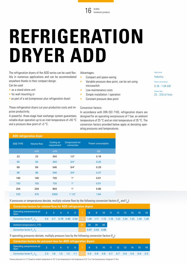
The refrigeration dryers of the ADD series can be used flex-ibly in numerous applications and can be accommodated anywhere thanks to their compact design.Can be used • as a stand-alone unit • for wall mounting or• as part of a set (compressor plus refrigeration dryer)
These refrigeration dryers cut your production costs and im-prove productivity. A powerful, three-stage heat exchange system guarantees reliable dryer operation up to an inlet temperature of +55 °C and a pressure dew point of +3 °C.
Advantages:• Compact and space-saving• Variable pressure dew point, can be set using
microswitch• Low maintenance costs• Simple installation / operation• Constant pressure dew point
Conversion factors:In accordance with DIN ISO 7183, refrigeration dryers are designed for an operating overpressure of 7 bar, an ambient temperature of 25 °C and an inlet temperature of 35 °C. The conversion factors provided below apply at deviating oper-ating pressures and temperatures.
Pressure dew point of +3 °C based on ambient temperature of +25 °C and compressed air inlet temperature of 35 °C at 7 bar (overpressure); refrigerant: R 134 a
Correction factors for volume flow for ADD refrigeration dryers
Operating overpressure pü (bar) 2 3 4 5 6 7 8 9 10 11 12 13 14 15 16
Correction factor Fc1-fpü 0.6 0.7 0.78 0.86 0.94 1 1.06 1.11 1.15 1.19 1.22 1.24 1.25 1.26 1.26
Ambient temperature tu (°C) 25 30 35 40
Correction factor Fc2-ftu 1 0.97 0.93 0.88
ADD wall mounting
"PLUS” variantwith coupled compressed air refrigeration dryer, can also be produced at later date
for selected series (on request)
Powerful heat exchange system
ADD refrigeration dryer
ADD TYPE Volume flow Cooling air requirement
Compressed air connection
Power consumption
m3/h m3/h kW
23 23 300 1/2" 0.18
50 50 300 3/4" 0.20
69 69 540 3/4" 0.29
96 96 540 3/4" 0.47
140 140 720 1" 0.61
150 150 720 1" 0.61
204 204 800 1" 0.86
310 310 2300 1 1/2" 1.04
Premium version available for
Application
IndustryPower consumption
0.18 - 1.04 kWVolume flow
23 - 310 m3/min
If pressures or temperatures deviate, multiply volume flow by the following conversion factors (ftu and fpü):
Correction factors for pressure loss for ADD refrigeration dryers
Operating overpressure pü (bar) 2 3 4 5 6 7 8 9 10 11 12 13 14 15 16
Correction factor Fc1-fdp 2.3 1.8 1.5 1.3 1.1 1 0.9 0.8 0.8 0.7 0.7 0.6 0.6 0.6 0.5
If operating pressures deviate, multiply pressure loss by the following conversion factors (fdp):

+ Reliable and low-maintenance
+ Footprint of less than 1 m2 is needed
+ Low noise level thanks to exceptional acoustic insulation
ALMiGtreatment products
ALMiGtreatment products16 17
REFRIGERATION DRYER ADD
Can be used flexibly
Simpleoperation
The refrigeration dryers of the ADD series can be used flex-ibly in numerous applications and can be accommodated anywhere thanks to their compact design.Can be used • as a stand-alone unit • for wall mounting or• as part of a set (compressor plus refrigeration dryer)
These refrigeration dryers cut your production costs and im-prove productivity. A powerful, three-stage heat exchange system guarantees reliable dryer operation up to an inlet temperature of +55 °C and a pressure dew point of +3 °C.
Advantages:• Compact and space-saving• Variable pressure dew point, can be set using
microswitch• Low maintenance costs• Simple installation / operation• Constant pressure dew point
Conversion factors:In accordance with DIN ISO 7183, refrigeration dryers are designed for an operating overpressure of 7 bar, an ambient temperature of 25 °C and an inlet temperature of 35 °C. The conversion factors provided below apply at deviating oper-ating pressures and temperatures.
Pressure dew point of +3 °C based on ambient temperature of +25 °C and compressed air inlet temperature of 35 °C at 7 bar (overpressure); refrigerant: R 134 a
Correction factors for volume flow for ADD refrigeration dryers
Operating overpressure pü (bar) 2 3 4 5 6 7 8 9 10 11 12 13 14 15 16
Correction factor Fc1-fpü 0.6 0.7 0.78 0.86 0.94 1 1.06 1.11 1.15 1.19 1.22 1.24 1.25 1.26 1.26
Ambient temperature tu (°C) 25 30 35 40
Correction factor Fc2-ftu 1 0.97 0.93 0.88
ADD wall mounting
"PLUS” variantwith coupled compressed air refrigeration dryer, can also be produced at later date
for selected series (on request)
Powerful heat exchange system
ADD refrigeration dryer
ADD TYPE Volume flow Cooling air requirement
Compressed air connection
Power consumption
m3/h m3/h kW
23 23 300 1/2" 0.18
50 50 300 3/4" 0.20
69 69 540 3/4" 0.29
96 96 540 3/4" 0.47
140 140 720 1" 0.61
150 150 720 1" 0.61
204 204 800 1" 0.86
310 310 2300 1 1/2" 1.04
Premium version available for
Application
IndustryPower consumption
0.18 - 1.04 kWVolume flow
23 - 310 m3/min
If pressures or temperatures deviate, multiply volume flow by the following conversion factors (ftu and fpü):
Correction factors for pressure loss for ADD refrigeration dryers
Operating overpressure pü (bar) 2 3 4 5 6 7 8 9 10 11 12 13 14 15 16
Correction factor Fc1-fdp 2.3 1.8 1.5 1.3 1.1 1 0.9 0.8 0.8 0.7 0.7 0.6 0.6 0.6 0.5
If operating pressures deviate, multiply pressure loss by the following conversion factors (fdp):

+ Cold regeneration
+ Compact and space-saving
+ Simple installation and operation
+ Low maintenance costs
ALMiGtreatment products
ALMiGtreatment products18 19
ALM-CD / ALM-CCD ADSORPTION DRYER
Application
IndustryPressure dew point
ALM-CCD: -40 °C, -70 °CALM-CD: -20 °C, -40 °C, -70 °C Nominal throughput at inlet
up to 9400 m3/hOperating pressure
4 - 16 barAmbient temperature
+5 °C to +50 °C
Adsorption dryers are used in cases where drier compressed air is needed than can be achieved with a refrigeration dry-er. In these dryers, the water vapour is deposited on and bound to a desiccant and the humidity thereby removed from the compressed air. The cold-regenerative ALM-CCD/-CD adsorption dryers are used wherever compressed air is being dried to a pressure dew point of –20 °C, –40 °C or –70 °C.The series offer a compact design and a simple operation.
Design: Vnom = 2000 m3/hInlet temperature = 30 °COperating overpressure = 10 bar
1Refers to intake status of 1 bar (abs) and 20 °C, 7 bar (overpressure) and 35 °C inlet temperature, pressure dew point -40 °C; Pressure dew point: ALM-CCD –40 °C at 100%, –70 °C at approx. 85% nominal load; ALM-CD –20 °C, –40 °C, –70 °C at 100% nominal load; operating overpressure: ALM-CCD 3 - 10 bar; ALM-CD 4 - 10 bar, 16-bar version on request
ALM-CCD / ALM-CD
TYPE Nominal throughput at inlet1
Average controlled air flow – -40 °C Width Height Depth Weight Connection
ALM-CCD m3/h m3/h mm mm mm kg G
10 9 1.8 516 775 157 29 R3/8"
20 17 3.4 516 775 157 37 R3/8"
30 25 5 516 775 157 51 R3/8"
40 35 7 669 775 208 69 R3/8"
50 45 9 669 775 208 71 R1/2"
ALM-CD
110 100 15 750 1950 750 180 R3/4"
170 160 24 750 1950 750 220 R3/4"
320 300 45 1150 1980 750 400 R1"
430 400 60 1150 1980 750 430 R1 1/2"
650 600 90 1150 1990 750 540 R1 1/2"
800 750 113 1150 1990 750 645 R2 "
1000 950 143 1150 2000 750 815 R2"
1200 1150 172 1500 1930 1300 1020 DN 80
1600 1450 217 1500 1950 1400 1275 DN 80
1900 1750 262 1500 2070 1450 1430 DN 80
2300 2100 315 1500 2090 1500 1650 DN 80
2600 2450 367 1500 2190 1700 2000 DN 80
3000 2800 420 1700 2220 1750 2300 DN 80
4000 3700 555 1950 2300 1900 3230 DN 100
6200 5800 870 2400 2500 2040 4500 DN 100
8000 7500 1125 2690 2610 2300 5750 DN 150
10000 9400 1410 2820 2510 2560 6800 DN 150
Vnom
fp • fT
Vcorr =
2000 m3/h1.18 • 1.05
Vcorr = = 1615 m3/h
Calculated dryer size: ALM-CD 1900
Correction factors for ALM-CCD adsorption dryer
Operating overpres-sure pü (bar) 3 4 5 6 7 8 9 10
Correction factor fpü 0.25 0.39 0.56 0.77 1 1.13 1.25 1.38
Inlet temperature T (°C) 10 20 30 35 40 45 50
Correction factor fT 1 1 1 1 0.98 0.94 0.88
Correction factors for ALM-CD adsorption dryer
Operating overpres-sure pü (bar) 4 5 6 7 8 9 10 11 12 13 14 15 16
Correction factor fpü 0.78 0.86 0.93 1 1.06 1.12 1.18 1.23 1.28 1.33 1.38 1.43 1.47
Inlet temperature T (°C) 10 20 30 35 40 45 50
Correction factor fT 1.33 1.17 1.05 1 0.96 0.92 0.89
Easy to maintain structure
Alternating regenerating receivers

+ Heat-regenerative adsorption dryer
+ No fan or external blower needed
+ Simple installation and operation
+ Energy Management System (EMS) available as an option
ALMiGtreatment products
ALMiGtreatment products20 21
ALM-WD ADSORPTION DRYERThe heat-regenerative ALM-WD adsorption dryer is the right solution for all uses requiring a constant pressure dew point of -40 °C. At higher ratings in particular, heat-regenerative adsorp-tion dryers are more efficient and most notably more cost effective to run than cold-regenerative ones because virtu-ally no compressed air is lost as a result of aftercooling or regeneration of the desiccant. This is because, with heat-regenerative adsorption dryers, the desiccant is not dried with compressed air but by a heating element, which is heated to 150 °C.
Advantages:• Ideal positioning of heating elements in drying bed• Optimum use of regenerative energy• Low maintenance costs• Simple installation/operation• Constant pressure dew point
Design: Vnom = 2000 m3/hInlet temperature = 30 °COperating overpressure = 10 bar
1Refers to intake status of 1 bar (abs) and 20 °C, 7 bar (overpressure) and 35 °C inlet temperature, pressure dew point -40 °C
ALM-WD
TYPE Nominal throughput at inlet1
Average controlled air flow – -40 °C Width Height Depth Weight Connection
ALM-WD m3/h m3/h mm mm mm kg G
280 245 5 760 2170 450 290 R1"
450 400 9 1000 2280 500 435 R1 1/2"
730 653 14 1050 2620 550 670 R1 1/2"
880 785 17 1200 2750 600 740 R2"
1200 1026 23 1250 2750 650 760 R2"
1500 1282 28 1400 3050 700 1450 DN80
2200 1916 42 1550 3050 800 1670 DN80
2500 2250 50 1650 3050 900 1900 DN80
3000 2670 58 1850 3175 950 2300 DN100
4000 3590 79 1950 3175 1050 3000 DN100
4800 4280 94 2000 3175 1100 3300 DN100
Vnom
fp • fT
Vcorr =
2000 m3/h1.37 • 1
Vcorr = = 1460 m3/h
Calculated dryer size: ALM-WD 2200
Correction factors for ALM-WD adsorption dryer
Operating overpressure pü (bar) 4 5 6 7 8 9 10 11 12 13 14 15 16
Correction factor fpü 0.63 0.75 0.88 1 1.12 1.15 1.37 on request
Inlet temperature T (°C) 10 20 30 35 40 45 50
Correction factor fT 1 1 1 1 0.60 0.38 0.25
Optional EMSEnergy management system
Efficient heat regeneration
Pressure dew point
-40 °C at 100% nominal load
Nominal throughput
245 - 4280 m3/hOperating pressure
4 - 16 bar (overpressure)Ambient temperature
+5 °C to +50 °C

+ Complete operational reliability
+ Maximum performance, safety and quality
+ Constant efficiency
ALMiGtreatment products
ALMiGtreatment products22 23
ACTIVE CARBON ADSORBER ALM-ACThe ALM-AC active carbon adsorber supplies absolutely oil-free, taste- and odour-neutral compressed air. The special active carbon ensures that oil vapour is adsorbed from the compressed air.
The ALM-AC active carbon adsorber guarantees:• Freedom from oil with a residual oil content ≤0.003 mg/
m3 through high adsorption of oil vapour. Inlet require-ments: DTP +3 °C.
• Active carbon life of around 10,000 operating hours.• Complete operational reliability.• Maximum performance, safety and quality.• Constant efficiency.
Key data: • Residual oil content: ≤ 0.003 mg/m3
• Volume flows: 70 - 9300 m3/h• Operating pressure: 5 - 16 bar (overpressure)• Ambient temperature: +2 to +45 °C
Design: Vnom = 200 m3/hInlet temperature = 30 °COperating overpressure = 10 bar
1Refers to intake status of 1 bar (abs) and 20 °C, 7 bar (overpressure) and 35 °C inlet temperature
ALM-AC
TYPE Nominal throughput at inlet1 Width Height Depth Weight Connection
ALM-AC m3/h mm mm mm kg
75 70 350 1950 750 90 R1/2"
120 110 350 1950 750 110 R3/4"
170 160 350 1970 750 130 R3/4"
220 200 350 1980 750 160 R1"
320 300 550 1980 750 170 R1"
480 450 550 1990 750 215 R1 1/2"
690 650 550 1990 750 260 R11/2"
850 800 550 2000 750 330 R2"
1100 1000 899 2210 800 305 DN80
1300 1250 899 2500 800 340 DN80
1700 1600 1019 2380 960 325 DN80
2000 1900 1012 2380 1010 450 DN80
2400 2250 1077 2795 1010 480 DN100
2900 2700 1202 2830 1010 500 DN100
3800 3600 1202 2830 1010 520 DN100
5500 5150 1505 2830 1540 690 DN100
7500 7100 1565 2950 1540 960 DN150
9900 9300 1780 3265 1580 1150 DN150
Vnom
fp • fT
Vcorr =
200 m3/h1.7 • 1.17
Vcorr = = 101 m3/h
Calculated dryer size: ALM-AC 120
Correction factors for ALM-AC adsorption dryer
Operating overpressure pü (bar) 5 6 7 8 9 10 11 12 13 14 15 16
Correction factor fpü 0.75 0.88 1 1.06 1.12 1.17 1.22 1.27 1.32 1.37 1.41 1.46
Inlet temperature T (°C) 25 30 35 40 45 50 55 60
Correction factor fT 3.1 1.7 1 0.57 0.33 0 0.11 0.061
Application
IndustryNominal throughput
70 - 9300 m3/hOperating pressure
5 - 16 bar (overpressure)Ambient temperature
+2 to +45 °C
Space-savingdesign
Long active carbon lives

ALMiG Kompressoren GmbHAdolf-Ehmann-Str. 273257 KöngenTel.: +49 (0)7024 [email protected]
www.almig.com Subject to errors and modifications Tr
eatm
ent_
0120
19
COMPRESSOR SYSTEMS MADE IN GERMANY