Embed Size (px)
Citation preview
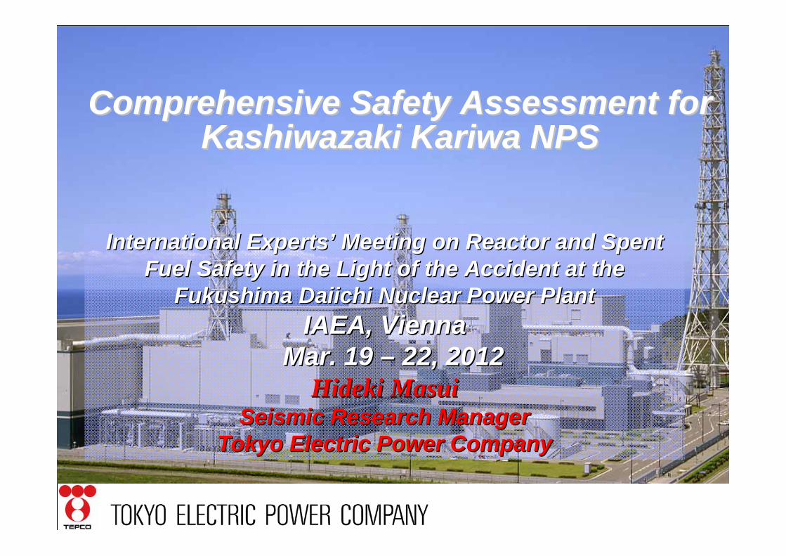
Comprehensive Safety Assessment for Comprehensive Safety Assessment for KashiwazakiKashiwazaki KariwaKariwa NPSNPS
International ExpertsInternational Experts’’ Meeting on Reactor and Spent Meeting on Reactor and Spent Fuel Safety in the Light of the Accident at the Fuel Safety in the Light of the Accident at the
Fukushima Daiichi Nuclear Power PlantFukushima Daiichi Nuclear Power PlantIAEA, ViennaIAEA, Vienna
Mar. 19 Mar. 19 –– 22, 201222, 2012Hideki MasuiHideki Masui
Seismic Research ManagerSeismic Research ManagerTokyo Electric Power CompanyTokyo Electric Power Company

2
Contents
1. Background and Concept of Comprehensive Safety Assessment
2. Methodology and Result of Assessment
3. Further Additional Safety Measures in Light of Fukushima Daiichi Accident
4. Continuous Improvement

3
1. Background and Concept of Comprehensive Safety Assessment

4
Background
Minister of Economy Trade and Industry and other two Ministers laid out a plan for assessmentJul.11, 2011
Reports of KK 1/7 were re-submitted to NISA after correction of editorial errorsMar.12, 2012
IAEA mission visited NISA to review NISA’s approach to assessment
Jan.23-31, 2012
Reports of Primary Assessment of Kashiwazaki Kariwa 1/7 were submitted to NISAJan.16 2012
NISA issued direction to utilities for implementing comprehensive safety assessmentJul.22, 2011
Chair of NSC issued request to Minister of Economy Trade and Industry for comprehensive safety assessment (stress test)
Jul.6, 2011
Fukushima Daiichi AccidentMar. 2011
EventDate
5
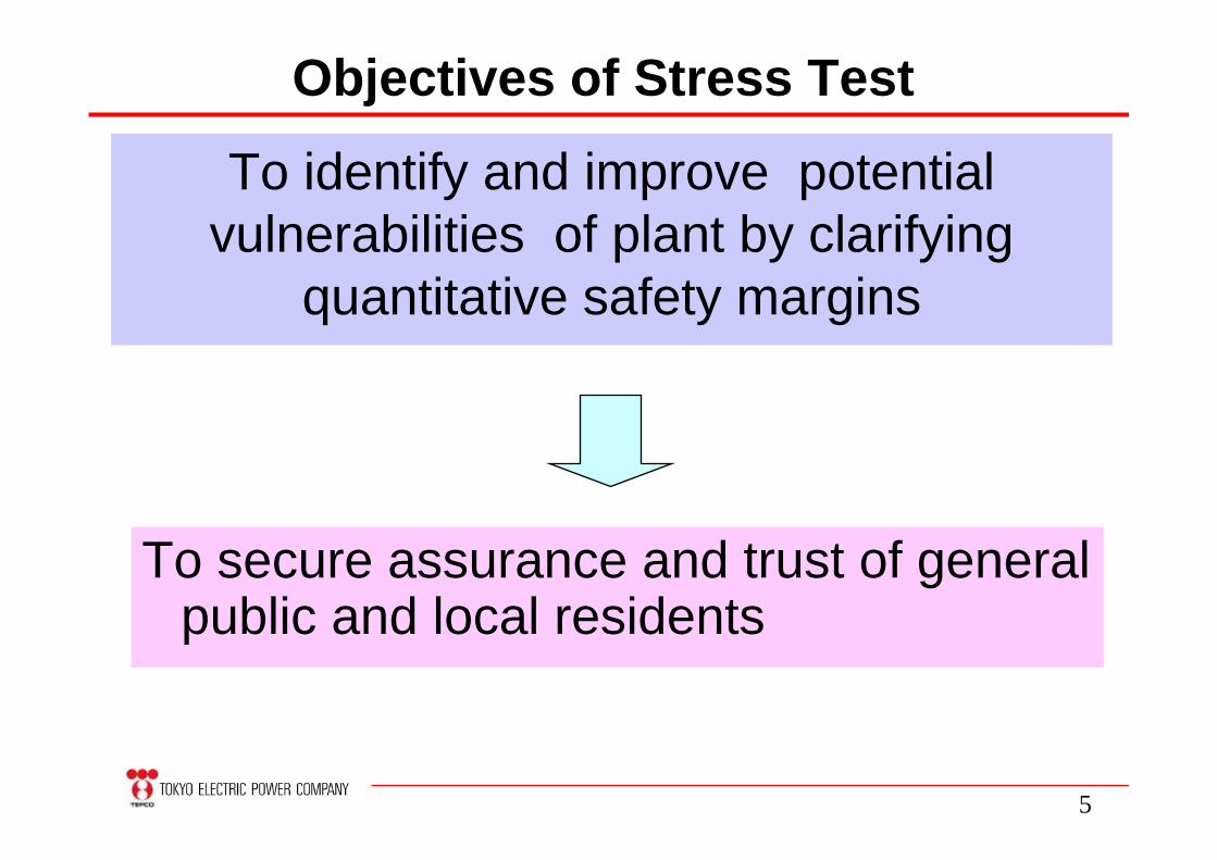
Objectives of Stress Test
To identify and improve potential vulnerabilities of plant by clarifying
quantitative safety margins
To secure assurance and trust of general public and local residents

6
Two-Step Approach for Stress Test
Same as primaryCombination of SBO
and LUHS(Other events may be
considered)
Earthquake, TsunamiCombination of quake
and tsunamiSBO, LUHS, SAM
Event
Realistic approachConservative approachMethod
Reactor, SFPReactor, SFPFacility
All operating plantPlants ready to start-up after outageTarget
SecondaryAssessment
PrimaryAssessment
Scope of this presentation

7
Primary and Secondary Assessment
Material strength confirmed by testing etc.
Prim
ary S
econ
dary
Allowable stress limits in code and standard (σd)
Calculated stress for design base earthquake (σc)
Tota
l Saf
ety
Mar
gin
Seismic margin for primary assessment = σd/ σc

8
TEPCO Nuclear Power StationsFukushima Daiichi NPS 4696MWeFukushima Daiichi NPS 4696MWe
Fukushima Daini NPS 4400MWeFukushima Daini NPS 4400MWe
Kashiwazaki Kariwa NPS 8212MWeKashiwazaki Kariwa NPS 8212MWe

9
The world’s largest nuclear power station with capacity of 8,212 MWe 5 units of Boiling Water Reactors (BWR with 1100 MWe -units 1 to 5) and
2 units of Advanced BWRs (ABWR with 1356 MWe -units 6 and 7) 4 units have been back online after NCO earthquake in 2007
Overview of Overview of KashiwazakiKashiwazaki--kariwakariwa NPSNPS
Outline of Kashiwazaki Kariwa NPS

10
Safety Measures Implemented After Fukushima Daiichi Accident
(Effectiveness of those measures will be clarified in assessment)

11
Tide Plate for Reactor Building
Tide Plate
Ventilation Sealed
Ventilation
Ventilation VentilationTide
BarrierTide Plate
Water Tight Door
AfterAfterBeforeBefore
Tide plate has been installed to R/B to tolerate tsunami up to 15m

12
Sealing Material
Waterproof Work
Sealed penetration
Water-tight door
Water-tight door
outer inner

13
Power Supply Car (14 on site) Portable Generator (20 on site)
Wheel Loader
Emergency Equipment on Site
Fire Engine (8 on site)

14
Gas Turbine Power Supply Car(4500kVA)
Emergency High Voltage Switchgear
Emergency metal-clad switchgear has been constructed in high ground to distribute emergency power
Hx/BT/B
R/B
500kV Power Supply Car
27m

15
Diversified Low Pressure Injection
D/D FP
MUWC
CSP
PCV
RHR(LPCI)
C/B
R/B
D/D FP
MUWC
Sea water
M
Fire truck
Filtratewater
RPV
ECSP
M M
M
In case of inoperable ECCS, 3 systems (MUWC, FP, Fire engine) are available for low pressure injection

16
RHR pump
RCWHx
RCWpump
Hx
Hx/B
Sea
Heat Exchanger
pumpPump
電動機
Seawater Pump
1
R/B
Mobile Heat Exchanger

17
Reliable PCV VentingPCV venting can be conducted more readily upon SBO by installing backup gas cylinder and modifying AOV
Stack
Rupture disk
PCV
D/W
S/C
RPVRPV
R/B
MMAOAOAOAO
AOAOAOAO
PLANT Vital power
D/W vent spare Cylinder
Operate MCR
PLANT Vital power
S/C vent spare Cylinder
Valve has been modified to allow manual operation
Stack
Rupture disk
PCV
D/W
S/C
RPVRPVRPVRPV
R/B
MMAOAOAOAO
AOAOAOAO
PLANT Vital power
D/W vent spare Cylinder
Operate MCR
PLANT Vital power
S/C vent spare Cylinder
Valve has been modified to allow manual operation

18
Diversified SFP Injection
D/D FP pump
Filtratewater
Fire truck MUWC FPMUW
D/D FP pump injectionFire truck(FP pipe)Fire truck(Hose)
R/B
C/B
Fire hydrantHose
Joint
SFP pool
FP pump and fire engine (via FP line or direct injection) are available for water injection to SFP

19
Diversified SFP Cooling
Power supply car
R/B
T/B
FPC
FPC H/x
Submersible pump
Hx/B
Unusable due to flooding
SFP pool
Joint
In case that mobile heat exchange is inoperable, submersible pump connected to existing system can remove heat from SFP

20
2.Methodology and Result of Assessment

21
Assessment of Safety Margin
Identification of Cliff Edge
Selection of Safety SSC
Screening of Initiating Event
Assessment of Effect of Safety Measures
Flow of Stress Test (Primary Assessment)
LOOP, SBO, Loss of RCW, Loss of DC power, ATWS, Loss of I/C, PCV/RPV Damage, R/B Damage, LOCA, Other transients
Safety-related SSCs are selected
Safety margins of SSCs are estimated
Cliff Edge (failure path with smallest safety margin) is identified by using event tree and fault tree
Effect of implemented Success path with largest safety margin (Cliff Edge) is identified by using event tree and fault tree
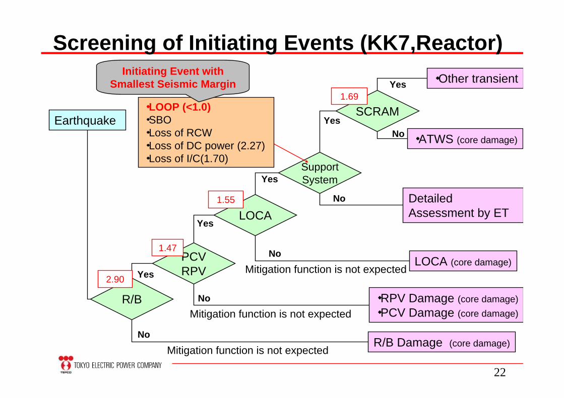
22
Screening of Initiating Events (KK7,Reactor)
R/B
R/B Damage (core damage)
・RPV Damage (core damage)・PCV Damage (core damage)
LOCA (core damage)PCVRPV
LOCA
Yes
Yes
No
No
NoMitigation function is not expected
Mitigation function is not expected
Mitigation function is not expected
Earthquake
SupportSystemYes
Detailed Assessment by ET
No
2.90
1.47
1.55
SCRAM1.69
・ATWS (core damage)
Yes
・Other transientYes
No
・LOOP (<1.0)・SBO・Loss of RCW・Loss of DC power (2.27)・Loss of I/C(1.70)
Initiating Event with Smallest Seismic Margin

23
Assessment by ET (KK7,Earthquake,Reactor)Quake Heat
SinkRx
pressureDC
powerHP
injection Depressurization LPinjection
RxHeat
Removal
PCVHeat
Removal
Core Damage
SRV RHR(LPCI)
LOOP SRV RCW EDG HPInjection・HPCS・RCIC
※next page
1.81 1.52 1.37 1.85
1.81 1.60
1.60RHR
(SHC)
RHR(S/C
cooling)
Core Damage
PCVventing
Yes Yes Yes
NoNo
No
Yes
Yes
No
Yes
No
Yes
No
Yes
No
Core Damage
No
Seismic Safety Marginbefore safety measures
(1.37)
1.60
1.58
1.37
1.37
1.37
Existing Safety Function
Additional Safety Function
SBO
※next page
Scenario before safety measures
Scenario after safety measures
Core Damage
LUHS
ColdShutdown
HotShutdown
HotShutdown

24
Seismic Safety Marginafter safety measures
(1.58)
HPinjection
ACPower Depressurization LP
injectionRx
HeatRemoval
PCVHeat
Removal
RCIC
(-)1.85
1.02
1.58
1.81 1.02
2.00or more
AlternativeInjection・MUW・FP(D/DFP)
PCVventing
Yes Yes Yes
NoNo
No
Yes
Yes
No
Yes
No
Yes
No
Yes
No
No
LUHS
SBO
Core Damage
Emergency Switchgear
SRV(Gas
Cylinder)
PowerSupply
Car
SRV
Core Damage
RHR(LPCI)
・Mobile Hx
RHR(SHC)
・Mobile Hx
Fire Engine
RHR(S/C
cooling)
AlternativeInjection・MUW・FP(D/DFP)
Core Damage
Fire Engine
(-)
(-)
(-)
1.81
(-)
1.58
Core Damage
Yes
No
Yes
No Yes
No
(-)
(-)
(-)
1.58
※ previouspage
※ previouspage
Scenario before safety measures
Scenario after safety measures
PCVVenting
ColdShutdown
HotShutdown
HotShutdown
HotShutdown
Existing Safety Function
Additional Safety Function
Assessment by ET (KK7,Earthquake,Reactor)

25
Example of Mitigation Function Assessment
Seismic Safety Margin: 1.58 This margin is reflected on ET
PCV Venting Failure
Atmospheric Control Piping Failure
SGTSPiping Failure
Piping Support Valve
or
2.34 1.63 5.00 5.76 1.58 4.58
1.63 1.58
Piping Support Valve
or
or 1.58

26
Screening of Initiating Events (KK7,Reactor)
R/B
R/B Damage (core damage)
・RPV Damage (core damage)・PCV Damage (core damage)
LOCA (core damage)PCVRPV
LOCA
Yes
Yes
No
No
NoMitigation function is not expected
Mitigation function is not expected
Mitigation function is not expected
Earthquake
SupportSystemYes
No
2.90
1.47
1.55
SCRAM1.69
・ATWS (core damage)
Yes
・Other transientYes
No
・LOOP (<1.0)・LOPA・Loss of RCW・Loss of DC power (2.27)・Loss of I/C(1.70)
Before safety measures: 1.37After safety measures : 1.58
Cliff edge after safety measure(RPV anchor volt damage)
Detailed Assessment by ET

27
Result of Stress Test (KK7, Earthquake)
SFPReactor
1.37(Loss of EDG)
1.47(RPV anchor volt damage)
After implemented
measure
1.37(Loss of EDG)
1.37(Loss of EDG)
Before implemented
measure
DBEGM=1209 gal
DBEGM: Design Basis Earthquake Ground Motion
Reactor: Due to implemented safety measure (power supply car etc), cliff edge will shift from LOOP to RPV damage
SFP: EDG failure can be covered by power supply car. However, margin of EDG is larger than that of MUW (alternative SFP injection) . Thereby, cliff edge stay unchanged.
28
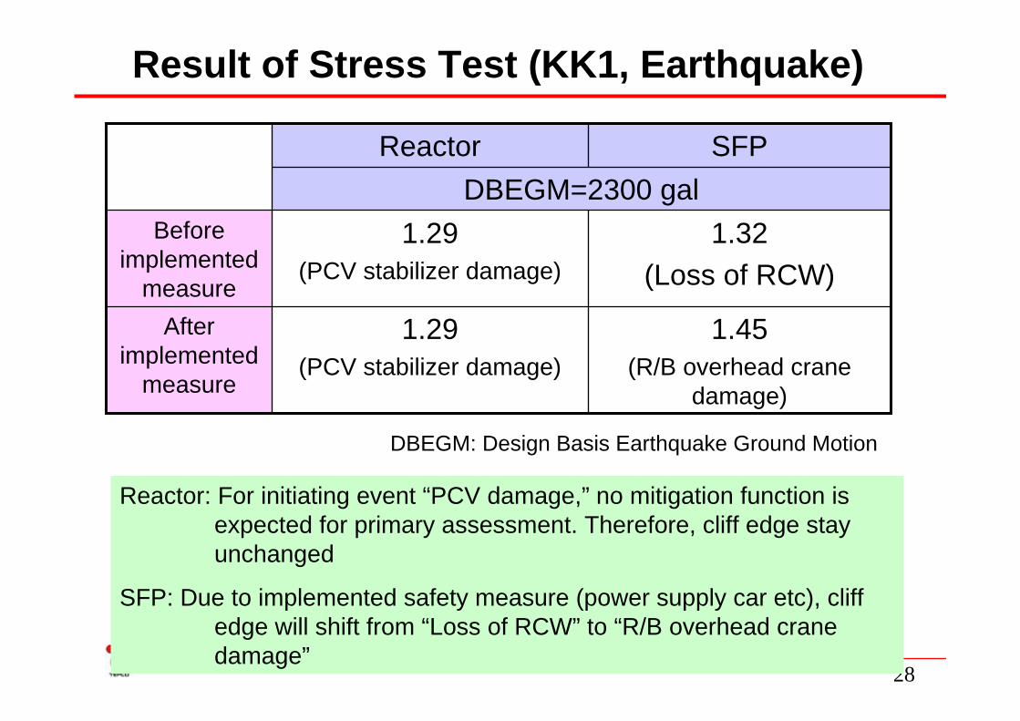
Result of Stress Test (KK1, Earthquake)
SFPReactor
1.45(R/B overhead crane
damage)
1.29(PCV stabilizer damage)
After implemented
measure
1.32(Loss of RCW)
1.29(PCV stabilizer damage)
Before implemented
measure
DBEGM=2300 gal
DBEGM: Design Basis Earthquake Ground Motion
Reactor: For initiating event “PCV damage,” no mitigation function is expected for primary assessment. Therefore, cliff edge stay unchanged
SFP: Due to implemented safety measure (power supply car etc), cliff edge will shift from “Loss of RCW” to “R/B overhead crane damage”

29
Result of Stress Test (KK1/7, Tsunami)
Before
3.3m
After
5m
15mKK1 (Reactor, SFP)
Before
3.3m
After
12m
15m
Design Tsunami Height
11.7m 11.7m
KK7 (Reactor, SFP)
Before implementation of safety measure: Allowable tsunami height is conservatively estimated to be equal to site height.
After implementation of safety measure: Allowable tsunami height is the one under the assumption of which water seal measures were conducted.
Margin Margin
30
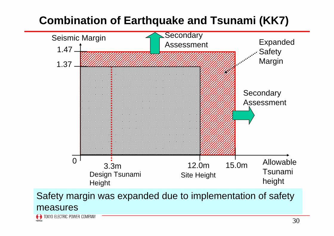
Combination of Earthquake and Tsunami (KK7)
Allowable Tsunami height
1.47
15.0m
1.37
12.0m
Seismic Margin Expanded Safety Margin
0 3.3mDesign Tsunami Height
Site Height
Safety margin was expanded due to implementation of safety measures
Secondary Assessment
Secondary Assessment

31
• Tolerance time is estimated after SBO or LUHS
• Tolerance time is determined by whichever shorter of the followings- Water supply time- Power supply time
• Conservative conditions are assumed:- All 7 reactors and SFPs become SBO or LUHS- No support is expected from outside
Assessment for SBO and LUHS

32
Result of Stress Test (SBO, KK7, Reactor in Operation)
Water
Power
Time
Water
Power
Time
CSP 0.7d(Minimum water level was changed)
Battery 16h
Fresh water 4.9d Sea water 7d
Power supply car 94d
Before
After
Battery 16h(Actual Life, 8h on design basis)
CSP 10h
About 10 hours
About 12 days
Due to concern of salt damage, 7 days was assumed.
Determined by capacity of fuel
Reactor + SFP

33
Result of Stress Test (SBO, KK7, Reactor Shutdown)
Water
Power
Time
Water
Power
Time
CSP 0.9d
Fresh water 5d Sea water 7d
Power supply car 99d
Before
After
About 5 hours (Time to water temperature reaches 100℃)
About 12 days
Due to concern of salt damage, 7 days was assumed.
Before safety measures, there was no specific procedures to inject water after SBO
SFP

34
Before After
196 days
Result of Stress Test (LUHS, KK7 Reactor/ SFP)
1 day
Determined by capacity of CSP and purified water tank
Determined by capacity of on-site fuel storage for power supply car
Mobile Heat Exchanger
Power Supply Car
35
Summary of Stress Test Result
• KK 1/7 have sufficient robustness against events beyond design basis through additional safety measures implemented after Fukushima Daiichi Accident
• In near future, secondary assessment will be conducted to identify and address potential vulnerabilities of plant.

36
3.Further Additional Safety Measures in light of Fukushima Daiichi Accident

37
④Support for emergencyresponse
Course of Event and Countermeasures<Event>Tsunami
SBO LUHS
Core damage
Hydrogen explosionRadiation Release
<Countermeasure>
①Protection from tsunami
②Prevention of core damage upon
Loss of AC/DC,LUHS
③Mitigation upon core damage
•Tsunami barrier•Tide barrier•Water proof sealing
Inundation of building
•Backup power •Heat removal•Diversified injection
•Roof venting•Reliable PCV venting
•Communication •Radiation Protection•Training

38
(1)Protection from Tsunami

39
Tsunami Barrier for Entire Site
Tsunami Barrier to prevent or deter the force of tsunami
3mT.P.+12m
T.P.+15m
10m
T.P.+5m
T.P.+15m
Reinforced Concrete Wall (Unit 1-4 )Cement-Soil Mixture Mound (Unit 5-7)

40
(2) Prevention of core damage upon Loss of AC/DC Power, LUHS
41
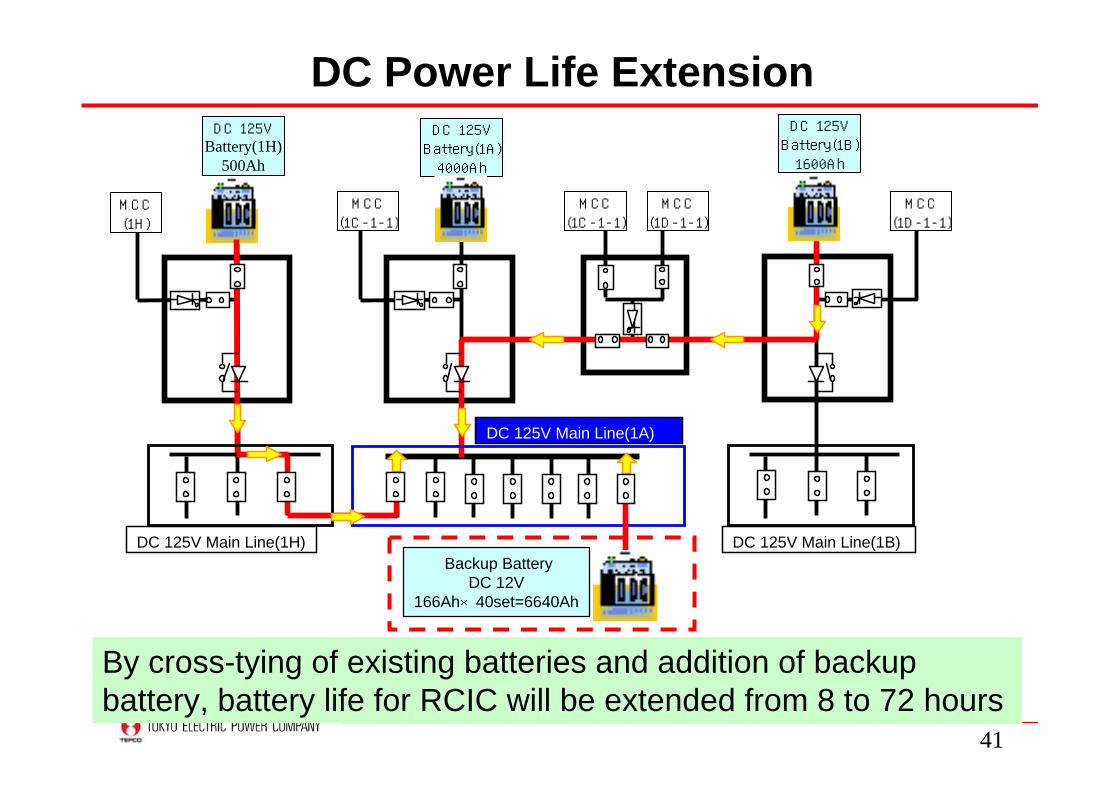
DC Power Life Extension
DC 125V Main Line(1A)
DC 125VBattery(1A)4000Ah
DC 125VBattery(1H)
500Ah
MCC(1C-1-1)
MCC(1H)
Backup BatteryDC 12V
166Ah×40set=6640Ah
MCC(1C-1-1)
MCC(1D-1-1)
DC 125VBattery(1B)1600Ah
MCC(1D-1-1)
DC 125V Main Line(1H) DC 125V Main Line(1B)
By cross-tying of existing batteries and addition of backup battery, battery life for RCIC will be extended from 8 to 72 hours
42
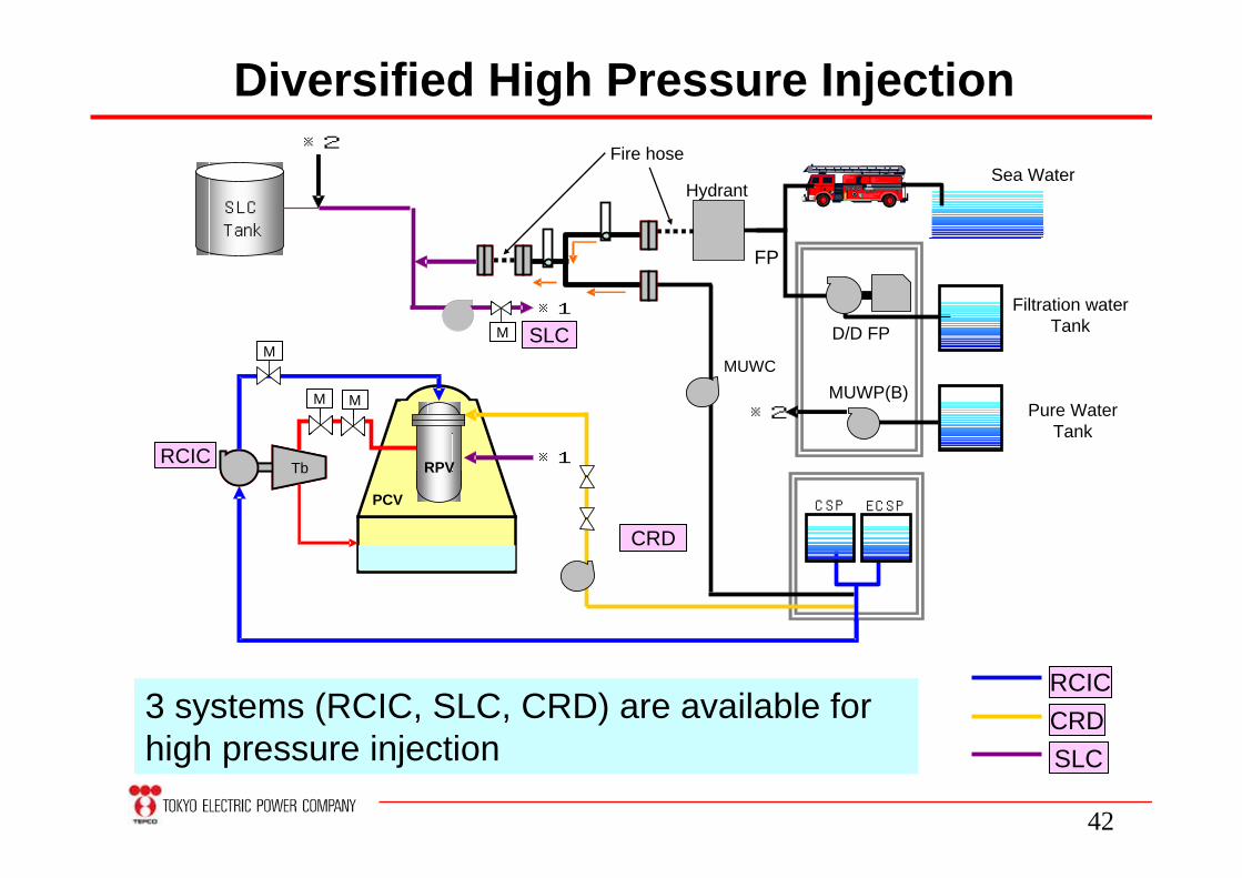
Diversified High Pressure Injection
PCV
ポンプ タービンTb
ECSP
RCIC
MUWP(B)
D/D FPFiltration water
Tank
Pure WaterTank
Sea WaterHydrant
FP
MUWC
SLC
SLCTank
※1
Fire hose※2
CRD
※2
※1
M
M M
M
CSP
RPV
RCICCRDSLC
3 systems (RCIC, SLC, CRD) are available for high pressure injection
43
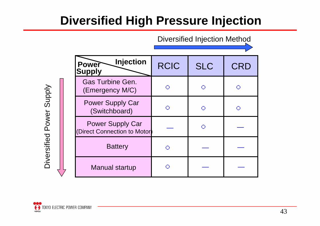
Diversified High Pressure Injection
Gas Turbine Gen.(Emergency M/C)
SLC CRD
Power Supply Car(Switchboard)
Power Supply Car(Direct Connection to Motor)
Battery
Manual startup
○
○
○
○
○
○
○
○
○
-
-
-
-
-
-
RCICInjectionPowerSupply
Diversified Injection MethodD
iver
sifie
d P
ower
Sup
ply

44
PCV
NO
RPV
Battery
Temporary Switch
Nitrogen cylinder
SRV
Backup cylinder
Nitrogen supply equipment
Depressurization by Safety Relief Valve
Backup gas cylinder and battery are prepared to facilitate SRV operation upon SBO

45
Construction of ReservoirReservoir is under construction on high grounds with capacity of 18,000m3

46
Effect of Reservoir
Water
Power
Time
CSP 0.7d
Battery 16hFresh water 4.9d Sea water 7d
Power supply car 94d
About 19 days
Fresh water 7d
Reservoir will extend SBO tolerance by 7 days (from 12 days to 19 days)
Reservoir

47
Underground Fuel Tank
Underground diesel fuel tank
Tank truck
Capacity: 150m3
Location: 35m above sea level
High voltage distribution board for emergencyGas turbine generator car
R/B(High voltage distribution board for emergency)
Underground diesel fuel tank
Underground fuel tanks are under construction to extend life of gas turbine generator

48
(3) Mitigation upon Core Damage

49
Roof Vent of Reactor Building
To facilitate hydrogen ventilation, roof vent has been installed at KK unit 1 and 7.
R/B
Roof Vent
Wire

50
sea
D/W spray
S/C spray
joint
Fire truck
R/B
Diversified PCV Cooling
FP-MUWC line
To mitigate overpressure and over temperature of PCV, PCV spray will be conducted by use of freshwater or sea water.

51
Filtered Containment Venting System
Filtered containment venting system will be introduced to minimize radiation release after core damage. Design is now under consideration.
Mist Separator
Water
SFP
Image of FCVS
(Image taken from NISA’s
Advisor’s meeting Dec.27, 2011)

52
(4)Enhanced Support for Emergency Response

53
On-site Emergency Response Center● Designed based on experience of quake hitting Kashiwazaki Kariwa in 2007
● Built with Base Isolated Structure.
● Equipped with communication devices, teleconference system, etc.
●Base Isolated Structure
Laminated Rubber
Movable Bearing

54
Communication Device and Network• In addition to existing diversified communication devices,
new network line and some devices were prepared• Batteries can be recharged by power supply car. Battery
life was extended
6 New Lines
Walkie-Talkie(9→30)
Power Supply Car(0→14)
Satellite phone(5→7)
Battery Life (3→8hrs)
Battery Life(2→8hrs)

55
Radiation Protection Equipment
• Shielding vests (with tungsten) are prepared• Dosimeters and face mask are stored at ERC• Equipments for RP can be shared among
nuclear licensees upon emergency
Shielding vests (image)・weight : about 18 kg・shielding ability:lead 2mm
Dosimeter face mask(shared among nuclear
licensees )

56
Training for Emergency Response• 5 comprehensive trainings have been conducted
so far after Fukushima Daiichi Accident • 4 daytime training and 1 night training. • Night training was carried out with temporary
lighting (Car headlight, flashlight, balloon light)
ERC
fire enginePower Supply Carwheel loader
Cable Laying Power Supply Car Connection of FP-line Balloon light

57
Development of New Procedures
・RCIC manual startup・SRV operation by battery・Injection by FP system・Manual operation of venting valve
・Securing power source・Extension of RCIC life・Injection by FP system・Seawater injection by fire engine・Operation of roof vent
Contents
Extensive Damage Mitigation GuidelineResponses against unforeseeable cause-free events
Severe Accident Management Guideline for TsunamiOutline
EDMGTsunami SAMG
To make improvised action more organized one, 2 new procedures have been developed

58
4.Continuous Improvement

59
Continuous Improvement
• From Fukushima Daiichi Accident, we have learned a lot of lessons.
• Based upon these lessons, we have been implementing additional safety measures.
• We are committed to continuously improve safety of our plants through collecting new findings domestically and internationally.
• Followings are some examples of initiatives to improve safety.
60
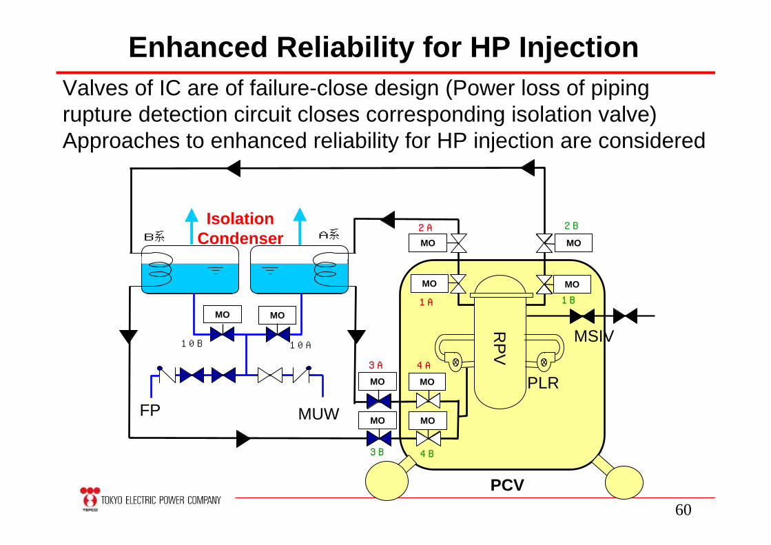
Enhanced Reliability for HP Injection
RP
V
PCV
FP MUW
MO
B系 A系
Isolation Condenser
1B
10A10B
3A
3B
PLR
MO
MO
MO
MO
MO
MO
MOMO
MO
1A
2B2A
4A
4B
MSIV
Valves of IC are of failure-close design (Power loss of piping rupture detection circuit closes corresponding isolation valve) Approaches to enhanced reliability for HP injection are considered

61
Enhanced Reliability for PCV Venting
AO
MO Main Stack
AO
AO
AOIA
IA
Solenoid Valve
Solenoid Valve
Failure close or open?
Necessity of those valves?
Relocation for less exposure?
Necessity of rupture disk?
Bypass line to control release timing?
PCV
D/W
S/C
RPV
RPV

62
Other Issues for Improving Safety
• Development of instrumentation resistant to severe accident condition
• Diversification of cooling function without AC power
• Reorganization of emergency response and operation staffing to deal with prolonged accident
• Establishment of transportation base for emergency material and staffing near plant

63
We are committed to improve the safety of the nuclear power plant through comprehensive safety assessment (Stress Test) and lessons learned from Fukushima Daiichi Accident.
For TEPCO, stress test is an opportunity to identify and address weakness of plants.
Concluding Remarks
We are going to keep you informed of any update in our English website. http://www.tepco.co.jp/en/index-e.html