Embed Size (px)
Citation preview

Advances in Concrete Construction, Vol. 7, No. 1 (2019) 39-50
DOI: https://doi.org/10.12989/acc.2019.7.1.039 39
Copyright © 2019 Techno-Press, Ltd. http://www.techno-press.org/?journal=acc&subpage=7 ISSN: 2287-5301 (Print), 2287-531X (Online)
1. Introduction
Reinforced concrete haunched beams (RCHBs) have
been extensively preferred in industrial buildings, bridges,
structural portal frames and framed buildings due to its
several advantages (Hou et al. 2015). Weight of structure
can be reduced and larger spans can be achieved by the use
of RCHBs instead of prismatic beam without a clear
deterioration in loading capacity (Naik and Manjunath
2017). Despite of these advantages, very few studies have
been investigated on the behavior of RCHBs so far.
Therefore, the experimental and theoretical background
about mechanical behavior of RCHBs should be improved.
However, it should be noted that since effective depth of
RCHBs is variable along the length of the beams, structural
analysis and mechanical behavior of them differ from the
analysis and behavior of prismatic beams. The first
experimental study was carried out by (Debaiky and
Elniema 1982) to investigate the shear behavior of RCHBs.
The authors proved that the nominal shear contribution of
the concrete and the longitudinal reinforcement were
influenced by the haunch’s inclination.
El-Niema (1988) published another study investigated
Corresponding author, Ph.D.
E-mail: [email protected] aAssistant Professor
E-mail: [email protected] bProfessor
E-mail: [email protected]
of T-section RCHBs. The results did not show substantial
difference in the mechanical behavior and strength capacity
as compared to the rectangular section RCHBs. (Stefanou
1983) conducted an experimental study of shear resistance
on reinforced concrete beams with non-prismatic sections
for two types of RCHBs. (Macleod and Houmsi 1994)
published a study about shear strength of RCHBs. The main
conclusion for both studies was decreasing the volume of
concrete in the beam due to increasing slope angle improves
the shear strength capacity and the failure to be more
ductile.
Tena et al. (2008) have tested eight prototypes of
RCHBs. The study investigated only one type of RCHBs
with different inclination angle. The authors concluded that
the RCHBs have more ductility than the prismatic beams
and the shear strength was increased in the RCHBs.
(Nghiep 2011) studied the shear design of RCHBs without
shear reinforcement where all of the RCHBs had inclined at
compression zone. The main outcome was that inclination
had a high influence on the shear capacity. Zanuy et al.
(2015) presented results of fatigue tests on the RCHBs
without stirrups. Two types of failure modes have been
obtained due to fatigue of the reinforcement or shear
fatigue. The study concluded that the RCHBs without shear
reinforcement are able to suffer fatigue. Hans et al. (2013)
tested prototype simply supported RCHBs under cyclic
loading were all the beams have the same inclination case,
the authors observed that haunched beams have a different
cyclic shear behavior with respect to prismatic beams,
having higher deformation and energy dissipation
capacities.
Chenwei et al. (2015) studied the shear failure
Comprehensive experimental investigation on mechanical behavior for types of reinforced concrete Haunched beam
Hasan M. Albegmprli1, M. Eren Gülşan2a and Abdulkadir Cevik2b
1Engineering Technical College, Building and Construction Engineering Department, Northern Technical University, Mosul, Iraq
2Civil Engineering Department, Gaziantep University, University Avenue - Central Campus, Gaziantep, Turkey
(Received July 20, 2018, Revised January 14, 2019, Accepted January 15, 2019)
Abstract. This study presents a comprehensive experimental investigation on mostly encountered types of Reinforced
Concrete Haunched Beams (RCHBs) where three modes of RCHBs investigated; the diversity of studied beams makes it a
pioneer in this topic. The experimental study consists of twenty RCHBs and four prismatic beams. Effects of important
parameters including beam type, the inclination angle, flexure and compressive reinforcement, shear reinforcement on
mechanical behavior and failure mode of each mode of RCHBs were examined in detail. Furthermore crack propagation at
certain load levels were inspected and visualized for each RCHB mode. The results confirm that RCHBs have different behavior
in shear as compared to the prismatic beams. At the same time, different mechanical behavior was observed between the modes
of RCHBs. Therefore, RCHBs were classified into three modes according to the inclination shape and mode of failure (Modes
A, B and C). However, it was observed that there is no significant difference between RCHBs and prismatic beams regarding
flexural behavior. Moreover, a new and unified formula was proposed to predict the critical effective depth of all modes of
RCHBs that is very useful to predict the critical section for failure.
Keywords: Haunched beams; load capacity; load-deflection curve; failure mode; crack propagation

Hasan M. Albegmprli, M. Eren Gülşan and Abdulkadir Cevik
Fig. 1 Details of the beams for Mode A
Fig. 2 Details of the beams for Mode B
mechanism of RCHBs. All beams were inclined from upper
face and the thickness increased in the support. The results
demonstrated that the bent tensile rebar has a negative
contribution to the shear capacity. Albegmprli et al. (2015)
carried out a theoretical study about the ultimate shear
capacity of RCHBs. The study performed stochastic and
reliability analyses based on nonlinear finite element
analysis. The authors evaluated the influence of material
properties and geometry parameters as uncertain values on
the mechanical behavior of RCHBs. Gulsan et al. (2018)
studied finite element modeling and proposed a new design
code formulation to improve the shear design equation of
ACI-318 to be more suitable to design the RCHBs, Eq. (4).
Although there are several experimental studies
regarding mechanical behavior of several modes of RCHBs,
there is no any study which investigated different modes of
these beams simultaneously. Moreover, the best choice
should be investigated by analysis of superiority of several
RCHBs modes to each other regarding load capacity, crack
pattern, post peak behavior, failure mode etc. The current
study aims to close this gap in literature. The main
objectives of this study are investigation of the mechanical
behavior of RCHBs as compared to prismatic beams,
influence of the differences between the modes of RCHBs
regarding to mechanical behavior, identification of crack
propagation and failure shape of all modes of RCHBs and
research on contribution of the shear reinforcement and
inclined longitudinal reinforcement to the behavior of
RCHBs.
2. Experimental program
2.1 The specimens
The experimental program includes 24 specimens
belonging to three modes depending on the beam shape.
Four of beams are prismatic and the others have variable
depths. The RCHBs were classified into three modes A,
B&C regarding to geometry of the beam. The geometries of
the tested beams are selected to have more simulation of
Fig. 3 Details of the beams for Mode C
Fig. 4 Testing the specimen
practical reality, the modes as follows:
• Mode A refers to RCHBs inclined at the compression
face. In this mode, the depth of the beams decreases in
the support.
• Mode B refers to RCHBs inclined at the tension face,
the depth of the beams decreases toward the support and
the sign of the inclination angle is assumed to be
positive.
• Mode C refers to RCHBs inclined at the tension face,
the depth of the beam increases toward the support and
the sign of the angle is assumed to be negative.
Total length, width and span length of all beams were
fixed 1700 mm, 150 mm and 1500 mm, respectively. The
effective depth of the beams at the mid-span was taken 260
mm for modes A&B, and 210 mm for mode C to achieve
the target shear span ratio condition (a/d>2.5). The
experimental program consisted, nine beams in Mode A,
seven beams in Mode B and eight beams in Mode C, the
details of RCHBs cases are detailed in Figs. 1, 2 and 3. The
geometries of all the beams are summarized in Table 1.
2.3 Testing procedure
All of the beams were tested using a 500 kN capacity
displacement controlled servo hydraulic flexural testing
machine. The load application was controlled using an
advanced hydraulic system. All of the beams were tested
according to four point bending test as shown in Fig. 4. The
span length is 1500 mm and the spacing between two
loading points is 200 mm. The beams were supported on
two steel rollers, one of them is allowed to rotate and other
is not permitted to prevent the axial load on the supports.
The loading tests were carried out by displacement
controlled mode; the displacement was increased by 0.2
mm at each loading step controlled by a displacement
40

Comprehensive experimental investigation on mechanical behavior for types of reinforced concrete Haunched beam
sensor until beam failure. The recorded values in each step
of loading consist of load, displacement and crack
propagation. Test configuration of the beams is shown in
Fig. 4. Following instruments were used for measuring and
monitoring during loading tests:
• A load cell to record the load value.
• Three linear variable displacement transducers
(LVDTs) to measure deflections in middle of the beam
and in middle of the span that extends between the
supports and the loading points.
• A high resolution camera for monitoring the beam and
following the crack propagation.
• A high magnification camera to detect formation of
cracks, especially for first cracks.
3. Testing results
3.1 Load capacity and failure modes
All of beams were tested in displacement controlled
mode until failure. As expected, the beams which were
without shear reinforcement failed in shear. In general, the
diagonal shear crack showed up suddenly between the
support and the loading point. The shear crack occurred on
either one side or both sides of the beam. However, the
Fig. 5 Failure modes
beams that were reinforced with stirrups in addition to main
reinforcement failed in flexural mode; see Fig. 5. The
beams without stirrups in A and B Modes failed in shear
and collapsed immediately after appearance of the diagonal
shear crack, except B3-0 & B3-1 beams where continued to
carry further load after the diagonal shear crack appeared
until collapse, the inclination angle in the corresponding
beams was 14.64°. On the other hand, the RCHBs without
stirrups in Mode C continued to carry further load after the
diagonal shear crack appeared until the concrete crushed
near the loading point. The maximum load capacity and the
Table 1 Geometries of the specimens
Beam Mode α° 1 ho 2 (mm) hs
3 (mm) As4 (mm2) As”
5 (mm2) ρv % 6
A0-0 - 0 300 300 603 (3Ø 16) 100 (2Ø 8) -
A0-2 - 0 300 300 603 (3Ø 16) 100 (2Ø 8) 0.67
A1-0 A 4.97 300 250 603 (3Ø 16) 100 (2Ø 8) -
A2-0 A 9.87 300 200 603 (3Ø 16) 100 (2Ø 8) -
A2-1 A 9.87 300 200 603 (3Ø 16) 308 (2Ø 14) -
A2-2 A 9.87 300 200 603 (3Ø 16) 100 (2Ø 8) 0.67
A3-0 A 14.62 300 150 603 (3Ø 16) 100 (2Ø 8) -
A3-1 A 14.62 300 150 603 (3Ø 16) 308 (2Ø 14) -
A3-2 A 14.62 300 150 603 (3Ø 16) 100 (2Ø 8) 0.67
B0-0 - 0 300 300 603 (3Ø 16) 100 (2Ø 8) -
B1-0 B 4.97 300 250 603 (3Ø 16) 100 (2Ø 8) -
B2-0 B 9.87 300 200 603 (3Ø 16) 100 (2Ø 8) -
B2-1 B 9.87 300 200 402 (2Ø 16) 100 (2Ø 8) -
B3-0 B 14.62 300 150 603 (3Ø 16) 100 (2Ø 8) -
B3-1 B 14.62 300 150 402 (2Ø 16) 100 (2Ø 8) -
B3-2 B 14.62 300 150 603 (3Ø 16) 100 (2Ø 8) 0.67
C0-0 - 0 250 250 603 (3Ø 16) 100 (2Ø 8) -
C1-0 C -4.97 250 300 603 (3Ø 16) 100 (2Ø 8) -
C2-0 C -9.87 250 350 603 (3Ø 16) 100 (2Ø 8) -
C2-1 C -9.87 250 350 402 (2Ø 16) 100 (2Ø 8) -
C2-2 C -9.87 250 350 603 (3Ø 16) 100 (2Ø 8) 0.67
C3-0 C -14.62 250 400 603 (3Ø 16) 100 (2Ø 8) -
C3-1 C -14.62 250 400 402 (2Ø 16) 100 (2Ø 8) -
C3-2 C -14.62 250 400 603 (3Ø 16) 100 (2Ø 8) 0.67 1 Inclination angle;
2 Depth at mid-span;
3 Depth at supports;
4 Flexural reinforcement;
5 Compression reinforcement;
6 Shear reinforcement percentages (Ø 8@100 mm).
Table 2 Concrete mix proportions
Material Gravel Sand Cement Fly Ash Silica Fume Water Visco-Crete
kg/m3 680 1100 250 215 35 150 5
41

Hasan M. Albegmprli, M. Eren Gülşan and Abdulkadir Cevik
Fig. 6 Load-deflection relationship of beams for Mode A
failure modes for the tested specimens are presented in
Table 3.
From the results, it can be observed that the shear
capacity of the beams in Mode C decreases with the
inclination angle, the negative contribution of the
inclination angle due to the vertical component of the axial
tensile stress of the flexural reinforcement. However, the
positive component for both of the vertical component of
the steel stresses in the beams of Mode B and compression
chord in Mode A affect positively on the shear strength. It is
also inferred from the results of Mode A and B beams that
increase of the inclination angle increases the load capacity
of the beams due to increasing the vertical component of
steel stresses.
Fig. 7 Load-deflection relationship of beams for Mode B
3.2 Load-deflection relationship
The values of deflection were measured and recorded
using linear variable displacement transducers (LVDTs).
CPD type transducers from TML Company were used to
measure the displacement and NI cDAQ-9184 data
acquisition tool from National Instrument Company was
used as data logger. The load-deflection relationships of all
beams without stirrup for each mode (A, B and C) are
shown in Figs. 6-8.
It can be observed from the figures that load capacities
of the beams increase as inclination angle value rises.
However, it is important to note that the stiffness of the
beams comes down with increase in the inclination angle
Table 3 Test results
Beam
code
fc
MPa
Ec
GPa
ft 1
MPa
Load kN Peak
Displacement mm
Effective
depth mm
Failure
Mode First crack Shear crack Collapse
A0-0 44.5 34.2 3.72 45 107 107 1.8 260 S2
A0-2 58 34.7 4.2 43 - 215 4.3 -- F3
A1-0 60 37 4.4 36 113.5 113.5 2222 250 S
A2-0 49 35.26 4.04 29 113.2 113.2 2.5 215 S
A2-1 51.5 33.2 4.3 26 115.3 115.3 2.433 215 S
A2-2 59 38.2 4.1 30 - 215 4.53 -- F
A3-0 42.5 34 3.7 29 121 121 2.54 180 S
A3-1 60 37.2 4.15 29 113 113 3.22 180 S
A3-2 59.9 37 4.2 29 - 214 4.82 -- F
B0-0 55 34.1 3.9 42 110 110.3 1.96 260 S
B1-0 53.5 35.2 4.65 39 108.2 108.2 1.9 250 S
B2-0 55.1 50.6 4.26 37 117 117 2.24 215 S
B2-1 53.9 33.2 4.0 36 91 91 2.57 215 S
B3-0 59.5 36.38 4.36 36 109 132 4.64 180 S
B3-1 51.5 35 3.6 33 111.2 123 4.57 180 S
B3-2 59 40.2 4.45 35 - 208 5.97 -- F
C0-0 60.7 34.2 3.87 21 94.4 94.4 2.62 210 S
C1-0 58.5 37.26 4.01 20 77.8 108 5.55 243 S
C2-0 44 33.1 3.69 18 66 101 5.74 265 S
C2-1 61 37 4.3 17 78.6 91.7 6.53 265 S
C2-2 65 39 4.1 26 - 175 5.4 -- F
C3-0 62 37.4 4.35 18 74.3 104 5.33 265 S
C3-1 50.1 32.74 4.3 18 67.2 95.5 5 265 S
C3-2 59 40 3.7 23 - 165 5.5 -- F 1 Splitting tensile strength;
2 Shear failure Mode;
3 Flexural failure Mode
42

Comprehensive experimental investigation on mechanical behavior for types of reinforced concrete Haunched beam
Fig. 8 Load-deflection relationship of beams for Mode C
due to reduction of moment on inertia for the section at
inclined segments. The deflection capability of the beams in
Modes B and C are higher as compared to the capability of
beams of Mode A. This means that the effect of inclined
main reinforcement is more apparent than the straight main
reinforcement.
3.3 Crack patterns In general, the failure mode of the RCHBs in shear
depends on the pattern of the diagonal shear cracks. During
loading process, several crack patterns formed in RCHBs
before collapse. Although, the crack propagation and mode
of failure have been widely investigated by several
experimental and theoretical studies for the prismatic
beams, there is very limited research in this topic for
RCHBs.
The beams in this study were designed to fail in shear or
in flexure. Eighteen beams were designed without shear
reinforcement to study the mechanism of the shear failure,
and six beams were designed with shear reinforcement to
study the flexural failure of RCHBs. In general, all of the
beams without stirrups collapsed in shear when diagonal
shear cracks appeared suddenly, whereas the beams with
shear stirrups failed in flexure or concrete crushing.
At early stage of loading, the flexure cracks appeared
along the beam where the first cracks initiated randomly
close to the mid-span or below of the loading point. The
trajectory of the cracks distribution varied for each beam.
Generally, the first cracks were perpendicular to the
longitudinal main reinforcements. At higher load, the cracks
were inclined and extended toward the position of the
loading points. An important observation for the flexure and
flexure-shear cracks was that they existed symmetrically on
both halves of the beam until collapse. When the diagonal
shear crack appeared, all of other cracks stopped growing
and some of them were closed. The patterns and the
positions of the diagonal shear cracks in beams that
collapsed due to diagonal shear crack are presented in Fig.
9. As shown in Fig. 9, the angle of the crack is nearly 45°
with the longitudinal flexural reinforcement for Mode A and
Mode B, and the angle does not show a definite trend in
Mode C.
3.4 Critical effective depth of shear
The RCHBs have variable depth and most of the design
codes do not consider the effective depth of RCHBs. The
shear effective depth of a RCHB depends on the position of
the major diagonal shear crack. Since, the depth is variable;
cross-sections are also variable along RCHBs. Therefore,
determination of effective depth to be used in shear capacity
calculations is confusing. Critical section concept is a
powerful and effective solution for this problem. Position of
major diagonal shear crack determines the location of the
critical section whose depth is called critical effective
depth. Based on experimental results, three different modes
of failure were observed regarding to the diagonal shear
crack as shown in Fig. 10.
The shear cracks in Modes A and B forms 45° with the
flexural reinforcement, the position of the critical section
for modes A and B are seen to be rather similar and it is
certain that the effective depth of the critical section is
greater than the support depth. Therefore, the slope signs in
Modes A and B are taken as positive. In Mode C, the slope
of the critical section was unsteady and so the effective
depth was recorded for each beam separately. Therefore,
Eq. (1) proposed to predict the effective depth of RCHBs
depending on experimental results using regression
analysis. The range of the inclination angle is limited
between −14.62o and +14.62o to apply the equation.
Fddsc
(1)
Where; 55.1tan04.31608.0
F
Where, dc is the shear effective depth of the critical
section, ds is the effective depth of the support and α is the
inclination angle.
3.5 Analysis of shear capacity for RCHBs Although RCHBs are widely used in reinforced concrete
structures, most design codes do not offer any instructions
for design of the beams. The sections 22.5.1.9 and
R22.5.1.9 of ACI 318-14 (2014) confirm to consider the
effect of inclined flexural compression in calculating the
shear strength of concrete where the internal shear at any
section is increased or decreased by the vertical component
of inclined flexural stresses. The section 27.4.5.3 of ACI
318-14 (2014) discusses the inclined shear crack in the
variable depth beams and recommends measuring the depth
at the mid-length of the crack. This part analyses of shear
capacity for the tested RCHBs which failed in shear, the
experimental strength compared with the estimated strength
according to ACI, a sophisticated model called Simplified
Modified Compression Field theory and an empirical
formula propose by Gulsan et al. (2018).
The influence of positive and negative contribution of
the inclined flexural reinforcement and the positive
contribution of compression chord added to the shear
formula of ACI code (Eq. (2)) in term of VCC. The
contribution of VCC is positive in Modes (A&B) and
negative in Mode C.
CCCVVV
(2)
43

Hasan M. Albegmprli, M. Eren Gülşan and Abdulkadir Cevik
Fig. 9 Diagonal shear cracks
(a) Mode A
(b) Mode B
(c) Mode C
Fig. 10 Failure modes for RCHBs
Where; dbfV cC '17.0 , )tan(. Z
MV
CC
Where, M is bending moment at analyzed section,
(z≈0.9d) is the arm between the compression and tension
forces in the section, and α is inclination angle.
Fig. 11 Values of β and θ for elements without transverse
reinforcement (Bentz et al. 2006)
Bentz et al. (2006), modified a sophisticated model
called Simplified Modified Compression Field theory to
predict the shear strength by considering the sum of the
forces in the z-direction for the body diagram shown in Fig.
11, the equation can be arranged to give.
cot'yzcsc
ffvvv
(3)
Where;
xexS
1000
1300
15001
4.0
deg752500
88.07000deg29
xe
x
S
16
35
g
x
xea
SS
Where, v is shear strength of the element, vc is the concrete
contribution, vs is the transverse reinforcement contribution,
β is constant value, fc’ is the compressive strength of
concrete, ρz is transverse reinforcement ratio, fy is the yield
strength of transverse reinforcement, εx is longitudinal strain
in compression strut, Sx is spacing between the stirrups and
ag is the aggregate maximum aggregate size.
Eq. (4) which proposed by the authors on the theoretical
part (Gulsan et al. 2018), the proposed model modified the
shear load capacity equation of prismatic beams which
adopted by ACI Code for RCHBs by introduction of critical
effective depth concept.
NFvCVVVVV
(1)
44
Comprehensive experimental investigation on mechanical behavior for types of reinforced concrete Haunched beam
Table 4 Shear strength analysis results
Where;
c
u
cuccC bd
M
dVfV )1716.0(
cyvv bdfV
tan130
220
"
c
ss
c
cc
NE
EA
fbd
fV
sin2.0 ysF fAV
Where; V is the ultimate nominal shear strength, VC is
the contribution of the concrete, Vv is the contribution of the
shear reinforcement, VN is the contribution of the inclined
compression chord in Mode C, VF is the contribution of the
inclined flexural reinforcement in Modes (A&B), ρc is the
reinforcement ratio at the critical section, Vu is shear force
and Mu is moment at analyzed section, ρv is the transverse
reinforcement ratio, fy is yield strength of the steel, As” is the
compression reinforcement area in Mode A, Es is elastic
modulus of steel, Ec is elastic modulus of concrete and α is
the inclination angle. The critical section is predicted in Eq.
(1).
Table 4, represents the shear strength analysis results.
Shear load capacity values of the RCHBs which are tested
in current study calculated according to the Eqs. (2), (3) and
(4). The correlations of the results are represented by the
mean bias of predicted strength to experimental result, the
variance of the bias by coefficient of variation (COV) and
R2 value. The average value of bias found approximately
equal to 1.0 for all the models but the variance of the results
for Eqs. (2), (3) and (4) which represented by the COV is
(0.13, 0.13 & 0.07), respectively. Whereas, R2 is (0.79, 0.67
Fig. 12 Influence of the inclination angle on shear strength
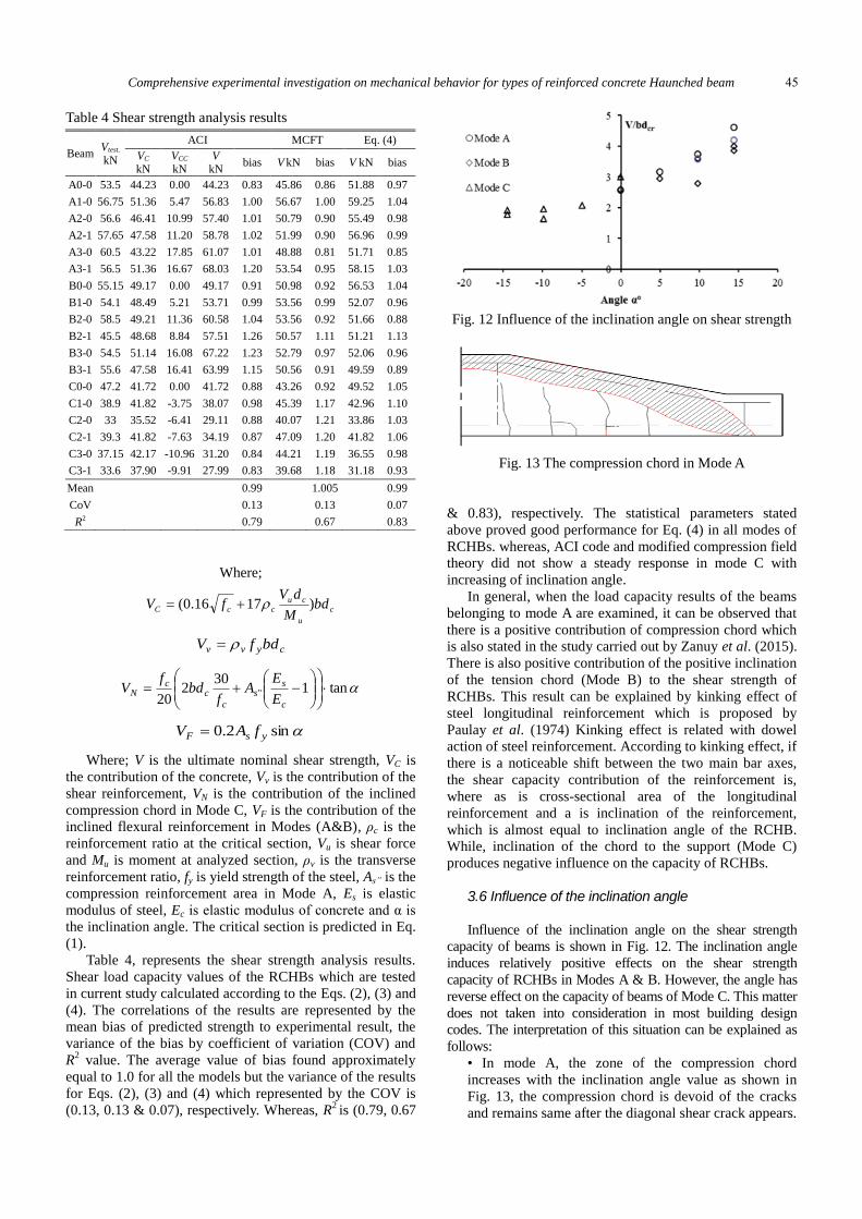
Fig. 13 The compression chord in Mode A
& 0.83), respectively. The statistical parameters stated
above proved good performance for Eq. (4) in all modes of
RCHBs. whereas, ACI code and modified compression field
theory did not show a steady response in mode C with
increasing of inclination angle.
In general, when the load capacity results of the beams
belonging to mode A are examined, it can be observed that
there is a positive contribution of compression chord which
is also stated in the study carried out by Zanuy et al. (2015).
There is also positive contribution of the positive inclination
of the tension chord (Mode B) to the shear strength of
RCHBs. This result can be explained by kinking effect of
steel longitudinal reinforcement which is proposed by
Paulay et al. (1974) Kinking effect is related with dowel
action of steel reinforcement. According to kinking effect, if
there is a noticeable shift between the two main bar axes,
the shear capacity contribution of the reinforcement is,
where as is cross-sectional area of the longitudinal
reinforcement and a is inclination of the reinforcement,
which is almost equal to inclination angle of the RCHB.
While, inclination of the chord to the support (Mode C)
produces negative influence on the capacity of RCHBs.
3.6 Influence of the inclination angle
Influence of the inclination angle on the shear strength
capacity of beams is shown in Fig. 12. The inclination angle
induces relatively positive effects on the shear strength
capacity of RCHBs in Modes A & B. However, the angle has
reverse effect on the capacity of beams of Mode C. This matter
does not taken into consideration in most building design
codes. The interpretation of this situation can be explained as
follows:
• In mode A, the zone of the compression chord
increases with the inclination angle value as shown in
Fig. 13, the compression chord is devoid of the cracks
and remains same after the diagonal shear crack appears.
Beam Vtest.
kN
ACI MCFT Eq. (4)
VC kN
VCC kN
V kN
bias V kN bias V kN bias
A0-0 53.5 44.23 0.00 44.23 0.83 45.86 0.86 51.88 0.97
A1-0 56.75 51.36 5.47 56.83 1.00 56.67 1.00 59.25 1.04
A2-0 56.6 46.41 10.99 57.40 1.01 50.79 0.90 55.49 0.98
A2-1 57.65 47.58 11.20 58.78 1.02 51.99 0.90 56.96 0.99
A3-0 60.5 43.22 17.85 61.07 1.01 48.88 0.81 51.71 0.85
A3-1 56.5 51.36 16.67 68.03 1.20 53.54 0.95 58.15 1.03
B0-0 55.15 49.17 0.00 49.17 0.91 50.98 0.92 56.53 1.04
B1-0 54.1 48.49 5.21 53.71 0.99 53.56 0.99 52.07 0.96
B2-0 58.5 49.21 11.36 60.58 1.04 53.56 0.92 51.66 0.88
B2-1 45.5 48.68 8.84 57.51 1.26 50.57 1.11 51.21 1.13
B3-0 54.5 51.14 16.08 67.22 1.23 52.79 0.97 52.06 0.96
B3-1 55.6 47.58 16.41 63.99 1.15 50.56 0.91 49.59 0.89
C0-0 47.2 41.72 0.00 41.72 0.88 43.26 0.92 49.52 1.05
C1-0 38.9 41.82 -3.75 38.07 0.98 45.39 1.17 42.96 1.10
C2-0 33 35.52 -6.41 29.11 0.88 40.07 1.21 33.86 1.03
C2-1 39.3 41.82 -7.63 34.19 0.87 47.09 1.20 41.82 1.06
C3-0 37.15 42.17 -10.96 31.20 0.84 44.21 1.19 36.55 0.98
C3-1 33.6 37.90 -9.91 27.99 0.83 39.68 1.18 31.18 0.93
Mean 0.99 1.005 0.99
CoV 0.13 0.13 0.07
R2 0.79 0.67 0.83
45

Hasan M. Albegmprli, M. Eren Gülşan and Abdulkadir Cevik
Fig. 14 Flexure failure
• In Mode B, the vertical component of the tensile stress
on the longitudinal main reinforcement causes positive
effect on the shear capacity of the beams due to its
direction. However, the vertical component of the stress
in the reinforcement for beams of Mode C exists in
reverse direction that leads to a negative effect on the
shear strength capacity.
3.7 Influence of the inclined reinforcement
In Mode A, when the capacity of A2-0 and A3-0 beams
(reinforcement area is 100 mm2 in compression zone) were
compared with A2-1 and A3-1 beams whose properties are
same with A2-0 and A3-0, respectively except
reinforcement area in compression zone (308 mm2), it was
concluded that inclined reinforcement in the compression
zone had slight effect on the capacity of beams. In Modes B
and C, the shear strength capacity was significantly affected
Fig. 15 Load- deflection relationships of beams fail in
flexure
by the area of the inclined longitudinal reinforcement in the
flexure zone due to the vertical component of the stresses
and the truss action of the inclined steel bars.
In Mode B, two steel reinforcement ratios were used
where the beams B2-0 & B3-0 were reinforced by 603 mm2
and the beams B2-1 & B3-1 were reinforced by 402 mm2.
The shear failure load of the beams B2-0 & B2-1 were
found to be 117 &91 kN, respectively. The variance in load
is 22 % due to variation of area of steel and 7% between the
beams B3-0 and B3-1. The similar situation exists for
beams of Mode C. For instance, the difference of the failure
load is found to be 9% between the beams C2-0 and C2-1
and 8% between the beams C3-0 and C3-1.
3.8 Flexural failure
Six beams out of twenty four beams were reinforced
with shear stirrups (ϕ 8 mm at each 100 mm). The beam
(A0-2) has a prismatic section and the other beams (A2-2,
A3-2, B3-2, C2-2 & C3-2) are RCHBs. The load-deflection
curves and crack patterns of these beams are shown in Fig.
14 and Fig. 15, respectively. The type of the failure for all
of these beams was flexure and concrete crushing as shown
in Fig. 14. While the reinforcement yielded at mid-span of
beams for Mode A, the position of yielding shifted to near
of inclination point for beams of Modes B&C. After
yielding, the load remained constant and the deflection
increased. After a while the load increased about 5-10 % of
the yield load till the concrete crushing.
The results does not show a significant difference in the
value of the maximum load between the prismatic beam and
the A series beams of A0-2, A2-2 & A3-2; the results are
215 kN, 215 kN and 214 kN, respectively. The explanation
is the flexural crack which led to failure is near of the
prismatic zone and the effective depth of the flexure is the
same of the prismatic beam.
However, as seen from the load-deflection curves (Fig.
15), the stiffness of RCHBs is smaller as compared to
prismatic beam due to variable depth along the RCHBs. The
beams of Mode C, C2-2 and C3-2 also failed in flexure or
concrete crushing at load 175 and 165 kN, respectively.
According to the results, it can be generally said that there
46

Comprehensive experimental investigation on mechanical behavior for types of reinforced concrete Haunched beam
is no a significant difference in the load capacity between
beams of Modes A and B and prismatic beam. However, the
stiffness of Mode A and B beams decreases slightly. Lastly,
the capacity and stiffness decreases apparently when the
beams of Mode C are preferred. In general, the reduction of
concrete volume in RCHBs did not reduce the efficiency of
the beam in flexural behavior.
3.9 Inspection of crack propagation
Reinforced concrete members have a complex crack
pattern depending on the geometry of the member and
material properties. The crack patterns that occur in RCHBs
can differ from ones that exist in prismatic beams.
Moreover, the form of cracks can exhibit variety between
modes of the RCHBs. The inspection of the crack
propagation for all of the tested beams is presented in the
Appendix part of the article. In general, the initial cracks
appear as perpendicular to the flexural reinforcement in low
load levels and develop at higher loads. The distinctive
points observed from the tests for crack propagation in the
beams can be listed as follows; 1) The ends of the flexural
cracks extend into the upper edge of the beam as parallel at
high loads for the beams of Mode A and Mode B. 2)
Splitting cracks occur along the reinforcement bar in beams
of Mode C, these cracks are result of the take-off force that
occurs from the reinforcement to the concrete cover. 3) The
crack propagation in the beams that fail in flexure mode is
similar for all of them. 4) In C series the concrete cover on
the bending point of the reinforcement took off due to the
concentration of the stresses in the bending point, the reason
is the negative component of the tensile stress in
reinforcement bars.
4. Conclusions
This study investigated the mechanical behavior of
different modes of Reinforced Concrete Haunched Beams
(RCHBs). An experimental program consisting of 24 beams
was implemented. The RCHBs were classified into three
modes namely as, A, B and C according to the inclination
shape. The parameters that considered in this study were the
inclination angle, the ratio of inclined reinforcement, shear
reinforcement and the geometry of the beam. Moreover,
cracks propagation was observed for each beam separately.
As a result of the study, the following conclusions can be
drawn:
• In general, two failure modes were observed as a result
of the loading tests, i.e., the beams without shear
stirrups fail due to diagonal shear, whereas flexure-
concrete crushing failure are observed in the beams that
contain shear stirrups.
• In the beams of Mode A and B, vertical component of
the stress that occurs in reinforcement contributes to the
load capacity of them and so increases the capacity.
However, beams of mode C shows contrary behavior
and the capacity of them are lower due to the negative
contribution of inclination angle to the shear strength.
Therefore the inclination angle is assumed to be positive
for beams of modes A and B, while negative for beams
of Mode C. Although, the effective depths the beams of
Mode C are higher, the shear strengths of them are
lower.
• For all considered RCHB Mode (A, B and C), stiffness
of the beams decreases slightly, as the inclination angle
increases.
• For all beams, the first crack is pure flexure crack that
appears in the middle of them. The flexure cracks form
perpendicular to the flexure reinforcement bars
regardless of the beam type. Flexural cracks continue to
propagate up to 50-60% of the ultimate load. At higher
load ranges, most of the cracks, except ones close to the
middle of the beams, turn to be inclined shear-flexure
cracks. Furthermore, for the beams without shear
reinforcement, propagation of the cracks in inclined
direction continues to upper edge of the beams until one
of the cracks suddenly expands to form the critical
diagonal shear crack that stops the formation and
propagation of other cracks and finally causes the
failure.
• Since the depth changes continuously in RCHBs,
determination of the critical section is very crucial for
correct prediction of the mechanical behavior of them.
Therefore, Eq. (1) proposed to predict the shear
effective depth for all modes of RCHBs by taking
inspection of crack propagation into account.
• From the results, can be concluded that mechanical
behavior of RCHBs that exhibit flexural behavior is
similar to the behavior of prismatic beams, except
beams of Mode C. Due to the inclination of beams with
negative angle, load capacities are lower and splitting
cracks appear in tension side for beams of Mode C.
• The post-peak behaviors of the beams differ from each
other. In prismatic beams and RCHBs of Modes A and
B, the load value tends to decrease after the critical
crack forms, except B3-0 & B3-1 beams which have
inclination angle of 14.62o. However, the load continues
to increase until the collapse of beams due to the
concrete fracture at loading point for beams of Mode C.
• Although RCHBs contain lower concrete volume as
compared to prismatic beams, shear strength capacity
increases in RCHBs and the flexural efficiency, crack
patterns and failure modes are not affected negatively.
Therefore, preference of reinforced concrete haunched
beams is more economical provided that geometry of
them is suitable for the constructions and structures.
References
Albegmprli, H.M. (2017), “Experimental investigation and
stochastic FE modeling of reinforced concrete haunched
beams”, PhD Thesis, Gaziantep University, Turkey.
Albegmprli, H.M., Abdulkadir, Ç ., Gulsan, M.E. and Kurtoglu,
A.E. (2015), “Reliability analysis of reinforced concrete
haunched beams shear capacity based on stochastic nonlinear
FE analysis”, Comput. Concrete, 15, 259-277.
Archundia-Aranda, H.I., Tena-Colunga, A. and Grande-Vega, A.
(2013), “Behavior of reinforced concrete haunched beams
subjected to cyclic shear loading”, Eng. Struct., 49, 27-42.
47

Hasan M. Albegmprli, M. Eren Gülşan and Abdulkadir Cevik
Bentz, E.C., Vecchio, F.J. and Collins, M.P. (2016), “Simplified
modified compression field theory for calculating shear strength
of reinforced concrete elements”, Struct. J., 103, 614-624.
Chenwei, H. and Matsumoto, K. (2015), “Shear failure mechanism
of reinforced concrete Haunched beams”, J. JSCE, 3, 230-245.
Debaiky, S.Y. and Elniema, E.I. (1982), “Behavior and strength of
reinforced concrete haunched beams in shear”, ACI Struct. J.,
79, 184-194.
DIN 1045-01 (2001), Tragwerke aus Beton, Stahlbeton und
Spannbeton, Teil 1Bemessungund Konstruktion, Beuth Verlag
GmbH, Berlin, Germany.
El-Niema, E.I. (1988), “Investigation of concrete haunched t-
beams under shear”, J. Struct. Eng., ASCE, 114, 917-930.
Gulsan, M.E., Albegmprli, H.M. and Cevik, A. (2018), “Finite
element and design code assessment of reinforced concrete
haunched beams”, Struct. Eng. Mech., 66, 423-438.
MacLeod, I.A. and Houmsi, A, (1994), “Shear strength of
haunched beams without shear reinforcement”, ACI Struct. J.,
91, 79-89.
Naik, P.K. and Manjunath, M. (2017), “Pushover analysis of
multi-storey frame structure with haunched beam”, Int. J. Trend
Res. Develop., 4(3), 333-336.
Nghiep, V.H. (2011), “Shear design of straight and haunched
concrete beams without stirrups”, Dissertation, Technischen
Universität Hamburg, Germany.
Paulay, T., Park, R. and Phillips, M.H. (1974), “Horizontal
construction joints in cast-in-place reinforced concrete”, Spec.
Pub., 42, 599-616.
Stefanou, G.D. (1983), “Shear resistance of reinforced concrete
beams with non-prismatic sections”, Eng. Fract. Mech., 18,
643-666.
Tena-Colunga, A., Hans, I.A. and Oscar, M.G. (2008), “Behavior
of reinforced concrete haunched beams subjected to static shear
loading”, Eng. Struct., 30, 478-492.
Zanuy, C., Juan, M.G. and Luis, A. (2015), “Fatigue behavior of
reinforced concrete Haunched beams without stirrups”, ACI
Struct. J., 12, 371-382.
CC
48

Comprehensive experimental investigation on mechanical behavior for types of reinforced concrete Haunched beam
Appendix: Cracks propagation
49

Hasan M. Albegmprli, M. Eren Gülşan and Abdulkadir Cevik
50