Embed Size (px)
Citation preview

CompositeFloor System
www.hambro.ws
Better Building Solutions
Co
mp
osite
Flo
or S
yste
m
SPC#05260
( 05 21 00 )
© C
anam
Gro
up In
c., 2
009
P
rinte
d in
Can
ada
01/0
9
MEP-HA Cartable-0109 09/01/2009 11:30 Page 1
INTRODUCTION
1
This manual has been developed in order to assist you
in understanding the Hambro®
Composite Floor System, and for you to have at your fingertips
the information necessary for the most efficient and economical
use of our Hambro products.
Suggested detailing and design information throughout
this manual illustrates methods of use. To achieve maximum economy and
to save valuable time we suggest that you contact your local Hambro representative.
He/she is qualified and prepared to assist in the selection of a Hambro
system that is best suited to your project’s requirements.
MEP-Technical Manual CDN 0408.qxd 08/04/2009 18:06 Page 3
GENERAL INFORMATION
1
1. GENERAL INFORMATION
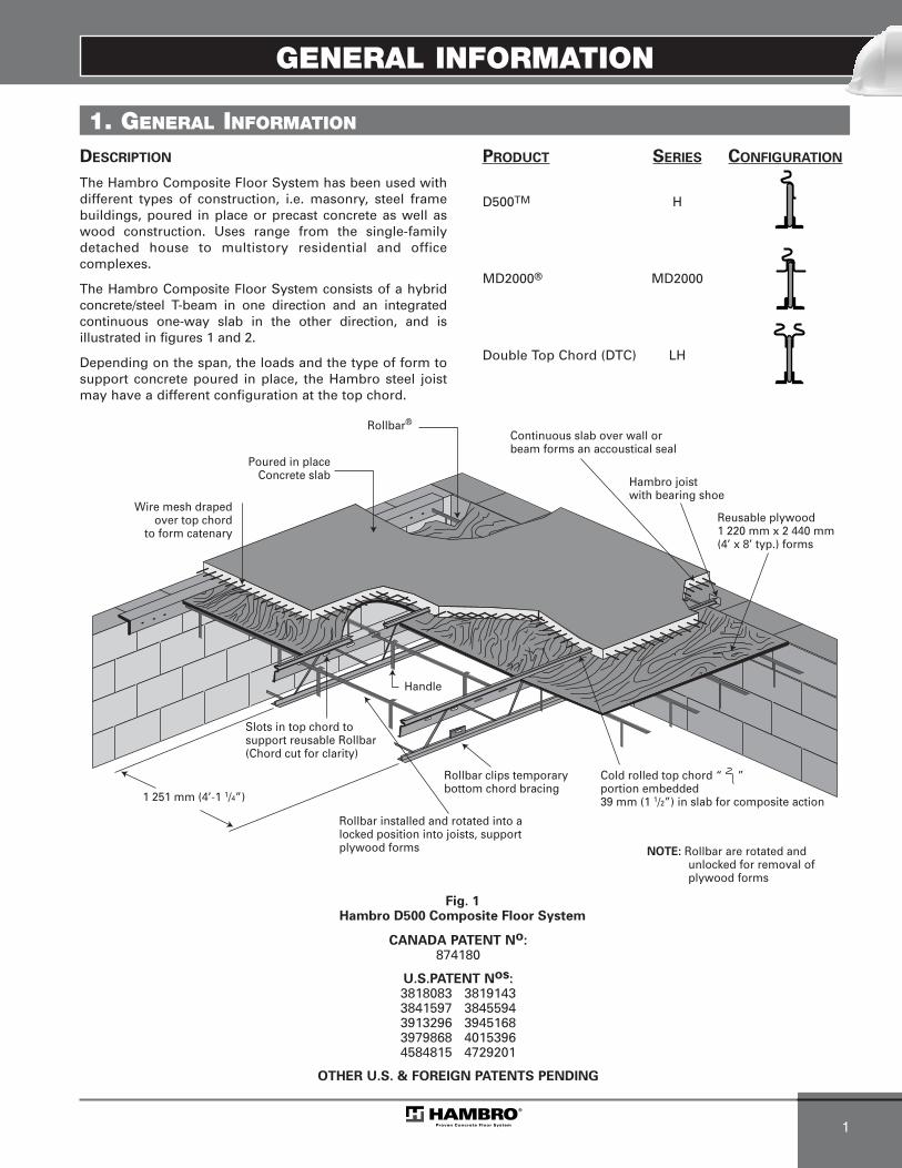
Rollbar®
Reusable plywood1 220 mm x 2 440 mm(4’ x 8’ typ.) forms
Hambro joistwith bearing shoe
Poured in placeConcrete slab
1 251 mm (4’-1 1/4”)
Handle
Wire mesh drapedover top chord
to form catenary
Rollbar clips temporarybottom chord bracing
NOTE: Rollbar are rotated and unlocked for removal of plywood forms
Slots in top chord to support reusable Rollbar(Chord cut for clarity)
Cold rolled top chord “ ”portion embedded 39 mm (1 1/2”) in slab for composite action
Continuous slab over wall orbeam forms an accoustical seal
Fig. 1Hambro D500 Composite Floor System
Rollbar installed and rotated into a locked position into joists, support plywood forms
DESCRIPTION
The Hambro Composite Floor System has been used with different types of construction, i.e. masonry, steel frame buildings, poured in place or precast concrete as well aswood construction. Uses range from the single-familydetached house to multistory residential and officecomplexes.
The Hambro Composite Floor System consists of a hybrid concrete/steel T-beam in one direction and an integrated continuous one-way slab in the other direction, and isillustrated in figures 1 and 2.
Depending on the span, the loads and the type of form to support concrete poured in place, the Hambro steel joistmay have a different configuration at the top chord.
PRODUCT SERIES CONFIGURATION
D500TM H
MD2000® MD2000
Double Top Chord (DTC) LH
CANADA PATENT No:874180
U.S.PATENT Nos:3818083 38191433841597 38455943913296 39451683979868 40153964584815 4729201
OTHER U.S. & FOREIGN PATENTS PENDING
MEP-Technical Manual CDN 0408.qxd 08/04/2009 18:06 Page 5
GENERAL INFORMATION
2
The unique top chord section has four basic functions:
1. It is a compression member component of theHambro non-composite joist during the concretingstage. The system is not shored.
2. It is a “high chair” for the welded wire mesh,developing negative moment capacity in theconcrete slab where it is required - over the joisttop chord.
3. It locks with and supports the slab forming system (Rollbar® and forms).
4. It automatically becomes a continuous shearconnector for the composite stage.
The bottom chord acts as a tension member during boththe concreting stage and the service life.
The web system, consisting of bent rods, ties the top and bottom chords together and resists the vertical shear in theconventional truss manner.
The concrete slab is reinforced with welded wire mesh atthe required locations and behaves structurally as acontinuous one-way reinforced concrete slab.
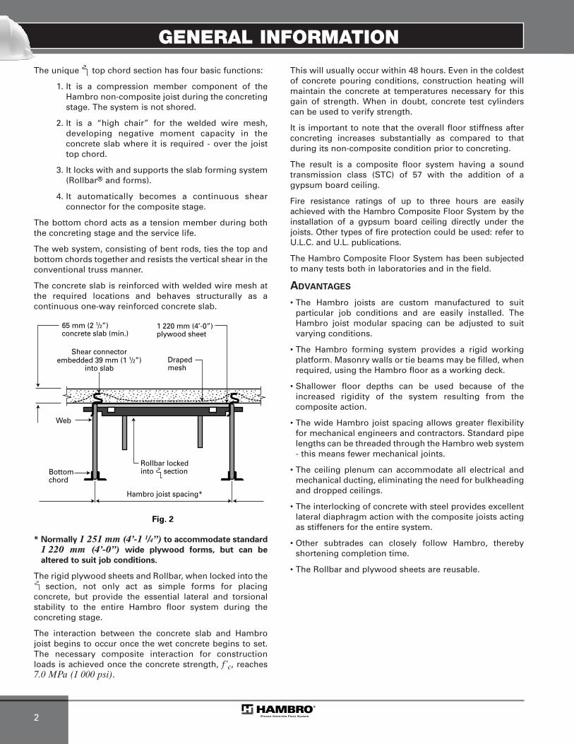
* Normally 1 251 mm (4’-1 1/4”) to accommodate standard
1 220 mm (4’-0”) wide plywood forms, but can be
altered to suit job conditions.
The rigid plywood sheets and Rollbar, when locked into thesection, not only act as simple forms for placing
concrete, but provide the essential lateral and torsionalstability to the entire Hambro floor system during theconcreting stage.
The interaction between the concrete slab and Hambrojoist begins to occur once the wet concrete begins to set.The necessary composite interaction for constructionloads is achieved once the concrete strength, f’c, reaches7.0 MPa (1 000 psi).
This will usually occur within 48 hours. Even in the coldestof concrete pouring conditions, construction heating willmaintain the concrete at temperatures necessary for thisgain of strength. When in doubt, concrete test cylinderscan be used to verify strength.
It is important to note that the overall floor stiffness after concreting increases substantially as compared to thatduring its non-composite condition prior to concreting.
The result is a composite floor system having a sound transmission class (STC) of 57 with the addition of agypsum board ceiling.
Fire resistance ratings of up to three hours are easilyachieved with the Hambro Composite Floor System by theinstallation of a gypsum board ceiling directly under thejoists. Other types of fire protection could be used: refer toU.L.C. and U.L. publications.
The Hambro Composite Floor System has been subjected to many tests both in laboratories and in the field.
ADVANTAGES
• The Hambro joists are custom manufactured to suitparticular job conditions and are easily installed. TheHambro joist modular spacing can be adjusted to suitvarying conditions.
• The Hambro forming system provides a rigid working platform. Masonry walls or tie beams may be filled, whenrequired, using the Hambro floor as a working deck.
• Shallower floor depths can be used because of theincreased rigidity of the system resulting from thecomposite action.
• The wide Hambro joist spacing allows greater flexibilityfor mechanical engineers and contractors. Standard pipelengths can be threaded through the Hambro web system- this means fewer mechanical joints.
• The ceiling plenum can accommodate all electrical and mechanical ducting, eliminating the need for bulkheading and dropped ceilings.
• The interlocking of concrete with steel provides excellent lateral diaphragm action with the composite joists actingas stiffeners for the entire system.
• Other subtrades can closely follow Hambro, therebyshortening completion time.
• The Rollbar and plywood sheets are reusable.
Shear connectorembedded 39 mm (1 1/2”)
into slab
Web
65 mm (2 1/2”) concrete slab (min.)
1 220 mm (4’-0”) plywood sheet
Draped mesh
Fig. 2
Bottomchord
Hambro joist spacing*
Rollbar lockedinto section
MEP-Technical Manual CDN 0408.qxd 08/04/2009 18:06 Page 6

APPROVALS AND FIRE RATINGS
1
APPROVALS 2. FIRE RATINGS
The Hambro Composite Floor System is approved,classified, listed, recognized, certified or accepted by thefollowing approving bodies or agencies:
1. CCMC No. 06292-Rirc.nrc-cnrc.gc.ca/ccmc/registry/13/06292 f.pdf
2. International Conference of Buildings Officials(ICBO) Report No. PFC 2869.www.icc-es.org/reports/pdf files/UBC/pfc2869.pdf
3. Miami-Date County, Florida, Acceptance No. 06-0420.02www.miamidade.gov
4. The cities of Los Angeles Report No. RR 25437www.ladbs.org.
Fire Protection floor/ceiling assemblies using Hambro®
have been tested by independent laboratories. Fire resistance ratings have been issued by UnderwritersLaboratories Inc. and by Underwriters Laboratories ofCanada (ULC) which cover gypsum board, accoustical tileand spray on protection systems. Reference to these published listings should be made in detailing ceiling construction. Check your UL directory for the latest updating of these listings, or see the UL website athttp://www.ul.com/database or ULC website atwww.ulc.ca/about ulc/online directories.asp
MEP-Technical Manual CDN 0408.qxd 08/04/2009 18:06 Page 7

FIRE RATINGS
2
Hambro Product UL/ULC/cULC Rating (hr.) Slab thickness (3) Ceiling Beam Rating
D500 LH (1) MD2000 (2) Design No. (mm) (in.) (hr.)
x x - I-5062 65 2 1/2 Gypboard 1/2” (12.7 mm) -
2 90 3 1/2 Gypboard 1/2” (12.7 mm) -
x x - I-5181 1/2 65 2 1/2 Gypboard 1/2” (12.7 mm) 2
2 55-75 2 1/4 - 3 Gypboard 1/2” (12.7 mm) 2
- - x I-522 2 75 3 Gypboard 1/2” (12.7 mm) 1 1/2
x - -I-800 1 - 1 1/2 - 2
65-70 2 1/2 -2 3/4 Spray on 1
- - x 70 2 3/4 Spray on 1
x x -G-003 2
65 2 1/2 Suspended or panel -
- - x 70 2 3/4 Suspended or panel -
x x x G-2132 75 3 Suspended or panel 2
3 100 4 Suspended or panel 3
x x -G-227 2
65 2 1/2 Suspended or panel 3
- - x 70 2 3/4 Suspended or panel 3
x x x G-228 2 80 3 1/4 Suspended or panel 2
x x x G-2292 75 3 Suspended or panel 2
3 100 4 Suspended or panel 3
x x -
G-524
1 - 2 65 2 1/2(3) Gypboard 1/2” (12.7 mm) 2
- - x 1 - 2 70 2 3/4(3) Gypboard 1/2” (12.7 mm) 2
x x x 3 90 3 1/2(3) Gypboard 1/2” (12.7 mm) 3
x x - G-525 3 80 3 1/4 Gypboard 5/8” (16 mm) 3
x x - G-702 1 - 2 - 3 Varies (3) Spray on -
x x - G-802 1 - 2 - 3 Varies (3) Spray on -
(1) For LH Series, add 1/4 inch concrete for slab thickness(2) For MD2000 series, the thickness shown in this table is above the decking (deck thickness = 1 1/2”)(3) Normal and lightweight concrete
MEP-Technical Manual CDN 0408.qxd 08/04/2009 18:06 Page 8
ACOUSTICAL PROPERTIES
1
3. ACOUSTICAL PROPERTIES
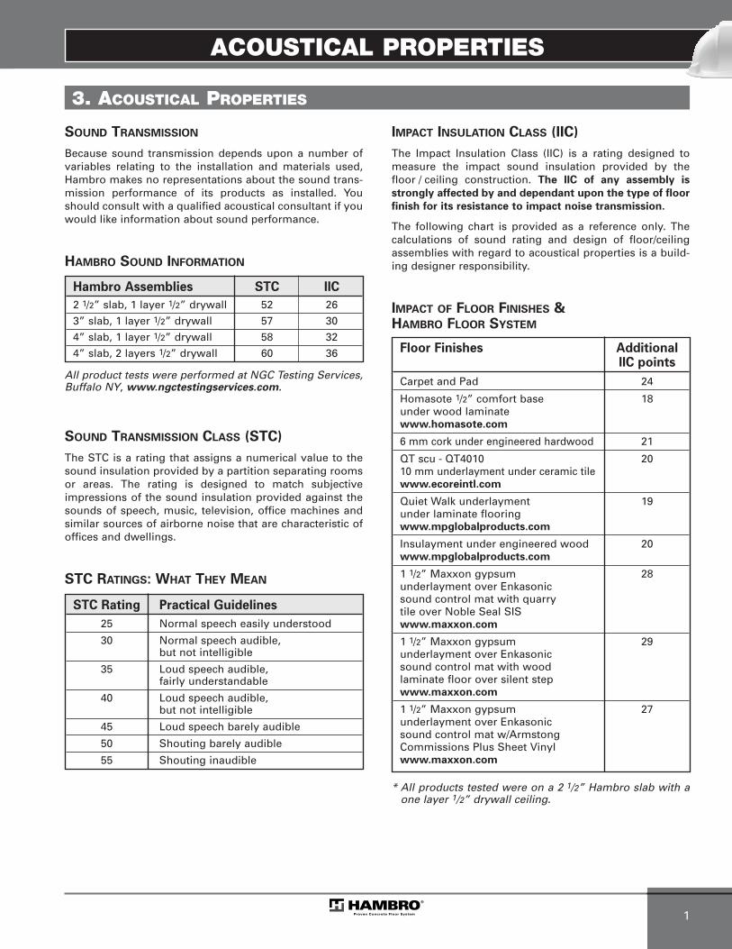
SOUND TRANSMISSION
Because sound transmission depends upon a number ofvariables relating to the installation and materials used,Hambro makes no representations about the sound trans-mission performance of its products as installed. Youshould consult with a qualified acoustical consultant if youwould like information about sound performance.
HAMBRO SOUND INFORMATION
All product tests were performed at NGC Testing Services,Buffalo NY, www.ngctestingservices.com.
SOUND TRANSMISSION CLASS (STC)
The STC is a rating that assigns a numerical value to thesound insulation provided by a partition separating roomsor areas. The rating is designed to match subjectiveimpressions of the sound insulation provided against thesounds of speech, music, television, office machines andsimilar sources of airborne noise that are characteristic ofoffices and dwellings.
STC RATINGS: WHAT THEY MEAN
IMPACT INSULATION CLASS (IIC)
The Impact Insulation Class (IIC) is a rating designed tomeasure the impact sound insulation provided by thefloor / ceiling construction. The IIC of any assembly is
strongly affected by and dependant upon the type of floor
finish for its resistance to impact noise transmission.
The following chart is provided as a reference only. Thecalculations of sound rating and design of floor/ceilingassemblies with regard to acoustical properties is a build-ing designer responsibility.
IMPACT OF FLOOR FINISHES & HAMBRO FLOOR SYSTEM
* All products tested were on a 2 1/2” Hambro slab with aone layer 1/2” drywall ceiling.
STC Rating Practical Guidelines
25 Normal speech easily understood
30 Normal speech audible, but not intelligible
35 Loud speech audible, fairly understandable
40 Loud speech audible, but not intelligible
45 Loud speech barely audible
50 Shouting barely audible
55 Shouting inaudible
Hambro Assemblies STC IIC
2 1/2” slab, 1 layer 1/2” drywall 52 26
3” slab, 1 layer 1/2” drywall 57 30
4” slab, 1 layer 1/2” drywall 58 32
4” slab, 2 layers 1/2” drywall 60 36 Floor Finishes AdditionalIIC points
Carpet and Pad 24
Homasote 1/2” comfort base 18under wood laminatewww.homasote.com
6 mm cork under engineered hardwood 21
QT scu - QT4010 20 10 mm underlayment under ceramic tilewww.ecoreintl.com
Quiet Walk underlayment 19under laminate flooringwww.mpglobalproducts.com
Insulayment under engineered wood 20www.mpglobalproducts.com
1 1/2” Maxxon gypsum 28underlayment over Enkasonicsound control mat with quarrytile over Noble Seal SISwww.maxxon.com
1 1/2” Maxxon gypsum 29underlayment over Enkasonicsound control mat with woodlaminate floor over silent stepwww.maxxon.com
1 1/2” Maxxon gypsum 27underlayment over Enkasonicsound control mat w/ArmstongCommissions Plus Sheet Vinylwww.maxxon.com
MEP-Technical Manual CDN 0408.qxd 08/04/2009 18:06 Page 9

ACOUSTICAL PROPERTIES
2
ACOUSTICAL ASSOCIATIONS & CONSULTANTS
The following is a list of acoustical associations that maybe found on the World Wide Web.
National Counsel of Acoustical Consultants –www.ncac.com
Canadian Acoustical Association – www.caa-aca.ca
Acoustical Society of America – www.asa.aip.org
Institute of noise Control Engineers – www.inceusa.org
As a convenience, Hambro is providing the following list ofvendors who have worked with this product. This list is notan endorsement. Hambro has no affiliation with theseproviders, and makes no representations concerning theirabilities.
Siebein Associates, Inc.
625 NW 60th Street, Suite CGainesville, FL 32607Telephone : 352-331-5111
Octave Acoustique, Inc.
Christian Martel, M.Sc. Arch963 Chemin RoyalSaint-Laurent-de-l’Île-d’Orléans, (Québec) Canada G0A 4N0Telephone : 418-828-0001
Acousti-Lab
Robert DucharmeC.P. 5028 Ste-Anne-des-Plaines (Québec) Canada J0N 1H0Telephone : 450-478-8828
MEP-Technical Manual CDN 0408.qxd 08/04/2009 18:06 Page 10

DESIGN PRINCIPLES AND CALCULATIONS
1
4. DESIGN PRINCIPLES AND CALCULATIONS
4.1 SLAB DESIGN
4.1.1 THE HAMBRO SLAB
The slab component of the Hambro Composite Floor Systembehaves as a continuous one-way slab carrying loadstransversely to the joists, and often is required to also actas a diaphragm carrying lateral loads to shear walls orother lateral load resisting elements.
The slab design is based on CSA Standard A23.3-04, Designof Concrete Structures which stipulates that in order toprovide adequate safety level, the factored effects shall beless than the factored resistance.
Where � = load factor, taking into account the proba-bility of exceeding the specified load
S = load effect (dead or live)
ø = performance factor
R = member resistance
4.1.2. EFFECTS OF LOADING
The Canadian concrete code (CSA Standard A23.3-04) cl. 9.2.3.1. requires that we consider dead load to act simul-taneously with the live load applied on:
i) Adjacent spans (maximum negative moment at support)
or
ii) Alternate spans (maximum positive moment at mid-span).
However, if criteria (a) thru (c) of cl. 9.3.3. are satisfied, the following approximate value may be used in the design ofone-way slabs. Refer to fig. 4 for location of the designmoments.
4.1.2.1 POSITIVE MOMENT
Exterior span:Mf = Wf L1
2 / 11 ... Location �
Interior span:Mf = Wf Li
2 / 16 ... Location �
4.1.2.2 NEGATIVE MOMENT
First interior support:Mf = Wf L2 / 10 ... Location �
At other interior supports:Mf = Wf L2 / 11 ... Location �
4.1.2.3 SHEAR
At face of first interior support:Vf = 1.15 Wf L1 / 2 ... Location �
At other interior supports:Vf = Wf Li / 2 ... Location �
Where Wf = Total factored design load
= 1.25 x dead + 1.5 x live
L1 = First interior span
Li = Interior spans
L = Average of two adjacent spans
Note: L is clear span (mm)S is joist spacing (mm)L = (S) - 45
Fig. 4
Spacing S1 Spacing S2
S2 /3
Spacing Si
1
Extra mesh at 1 & 2 when required
3 3
442 Location indexingnumbers
� S ≤ ø R
MEP-Technical Manual CDN 0408.qxd 08/04/2009 18:06 Page 11

DESIGN PRINCIPLES AND CALCULATIONS
2
4.1.2.4 CONCENTRATED LOAD
In addition to the previous verification, the NationalBuilding Code of Canada cl.4.1.5.10 (1) requires considera-tion of a minimum concentrated load to be applied over anarea of 750 mm x 750 mm. The magnitude of the loaddepends on the occupancy. This loading does not need tobeconsidered to act simultaneously with the specifieduniform live load.
The intensity of concentrated loads on slabs is reduceddue to lateral distribution. One of the accepted methods ofcalculating the “effective slab width” which is used byHambro actually appears in Section 317 of the BritishStandard Code of Practice CP114 and is reproducedin fig. 5. Note that the amount of lateral distributionincreases as the load moves closer to mid-span, andreaches a maximum of 0.3L to each side; the effective slab width resisting the load is a maximum ofload width + 0.6L.
An abbreviated summary of the calculations is shown in tables 6 and 7.
Fig. 5
Lateral Distribution of Concentrated Loads
X
L
AA
Load Slab
Section A-A
Effe
ctiv
e w
idth
0.3L
Load
wid
th
1.2
(X) (1-
X) L
MEP-Technical Manual CDN 0408.qxd 08/04/2009 18:06 Page 12
DESIGN PRINCIPLES AND CALCULATIONS
3
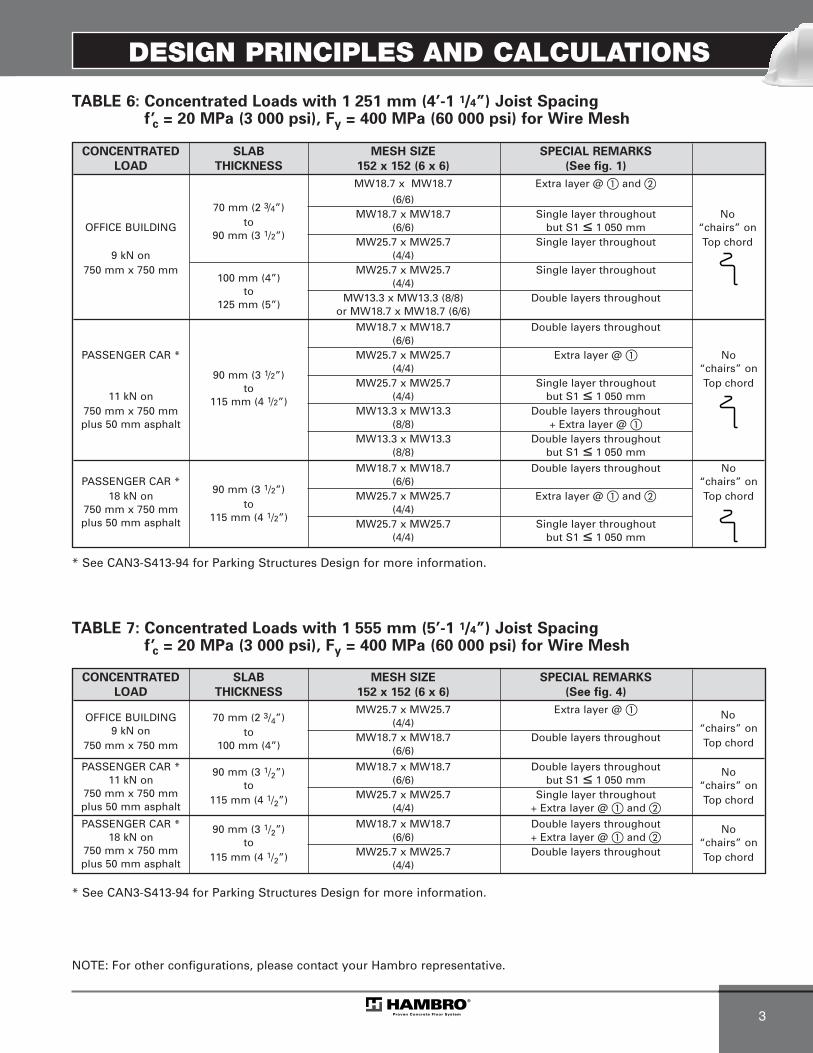
TABLE 6: Concentrated Loads with 1 251 mm (4’-1 1/4”) Joist Spacing f’c = 20 MPa (3 000 psi), Fy = 400 MPa (60 000 psi) for Wire Mesh
TABLE 7: Concentrated Loads with 1 555 mm (5’-1 1/4”) Joist Spacing f’c = 20 MPa (3 000 psi), Fy = 400 MPa (60 000 psi) for Wire Mesh
* See CAN3-S413-94 for Parking Structures Design for more information.
* See CAN3-S413-94 for Parking Structures Design for more information.
CONCENTRATED SLAB MESH SIZE SPECIAL REMARKS
LOAD THICKNESS 152 x 152 (6 x 6) (See fig. 4)
OFFICE BUILDINGMW25.7 x MW25.7 Extra layer @ � No
9 kN on70 mm (2 3/4”) (4/4) “chairs” on
750 mm x 750 mmto MW18.7 x MW18.7 Double layers throughout Top chord100 mm (4”) (6/6)
PASSENGER CAR * 90 mm (3 1/2”) MW18.7 x MW18.7 Double layers throughout No11 kN on to (6/6) but S1 ≤ 1 050 mm “chairs” on
750 mm x 750 mm115 mm (4 1/2”) MW25.7 x MW25.7 Single layer throughout Top chord
plus 50 mm asphalt (4/4) + Extra layer @ � and �
PASSENGER CAR * 90 mm (3 1/2”) MW18.7 x MW18.7 Double layers throughout No18 kN on to (6/6) + Extra layer @ � and � “chairs” on
750 mm x 750 mm115 mm (4 1/2”) MW25.7 x MW25.7 Double layers throughout Top chord
plus 50 mm asphalt (4/4)
NOTE: For other configurations, please contact your Hambro representative.
CONCENTRATED SLAB MESH SIZE SPECIAL REMARKS
LOAD THICKNESS 152 x 152 (6 x 6) (See fig. 1)
MW18.7 x MW18.7 Extra layer @ � and �
70 mm (2 3/4”)(6/6)
toMW18.7 x MW18.7 Single layer throughout No
OFFICE BUILDING90 mm (3 1/2”)
(6/6) but S1 ≤ 1 050 mm “chairs” onMW25.7 x MW25.7 Single layer throughout Top chord
9 kN on (4/4)750 mm x 750 mm
100 mm (4”)MW25.7 x MW25.7 Single layer throughout
to(4/4)
125 mm (5”)MW13.3 x MW13.3 (8/8) Double layers throughout
or MW18.7 x MW18.7 (6/6)
MW18.7 x MW18.7 Double layers throughout(6/6)
PASSENGER CAR * MW25.7 x MW25.7 Extra layer @ � No(4/4) “chairs” on
90 mm (3 1/2”)MW25.7 x MW25.7 Single layer throughout Top chord
11 kN onto
(4/4) but S1 ≤ 1 050 mm750 mm x 750 mm
115 mm (4 1/2”)MW13.3 x MW13.3 Double layers throughout
plus 50 mm asphalt (8/8) + Extra layer @ �MW13.3 x MW13.3 Double layers throughout
(8/8) but S1 ≤ 1 050 mm
MW18.7 x MW18.7 Double layers throughout NoPASSENGER CAR *
90 mm (3 1/2”)(6/6) “chairs” on
18 kN onto
MW25.7 x MW25.7 Extra layer @ � and � Top chord750 mm x 750 mm
115 mm (4 1/2”)(4/4)
plus 50 mm asphalt MW25.7 x MW25.7 Single layer throughout(4/4) but S1 ≤ 1 050 mm
MEP-Technical Manual CDN 0408.qxd 08/04/2009 18:06 Page 13

DESIGN PRINCIPLES AND CALCULATIONS
4
4.1.3 MOMENT CAPACITY
The factored moment resistance of a reinforced concrete section, using an equivalent rectangular concrete stress distribution is given by:
Mr = øsAs Fy (d - a/2)
a = depth of the equivalent concrete stress block
=øsAs Fy
�1øc f’cb
Where Fy = yield strength of reinforcing steel (400 MPa)
f’c = compressive strength of concrete (20 MPa)
As = area of reinforcing steel in the direction of analysis (mm2/m width)
�1 = 0.85 - 0.0015f’c ≥ 0.67
b = unit slab width (mm)
d = distance from extreme compression fiber to centroïd of tension reinforcement (mm)
(see tables 8 and 9 on pages 19 and 20)
øs = performance factor of reinforcing steel (0.85)
øc = performance factor of concrete (0.65)
4.1.3.1 SHEAR CAPACITY
The shear stress capacity V, which is a measure of diagonaltension, is unaffected by the embedment of the section asthis principal tensile crack would be inclined and radiate awayfrom the section.
The factored shear capacity is given by:
Vr = Vc = øc�ß f’c bwd
(CSA A23.3-04, clause 11.3.4)
Where � = 1.0 for normal density concrete
ß = 0.21 = (CSA A23.3-04, clause 11.3.6.3)
bw = b = width of slab
And øc, f’c and d are as previously described.
4.1.4 SERVICEABILITY LIMIT STATES
4.1.4.1. CRACK CONTROL PARAMETER
When the specified yield strength, Fy, for tension reinforce-ment exceeds 300 MPa, cross sections of maximum positiveand negative moments shall be so proportioned that thequantity Z does not exceed 30 kN/mm for interior exposureand 25 kN/mm for exterior exposure. Ref. CSA A23.3-04,clause 10.6.1.
The quantity Z limiting distribution of flexural reinforcementis given by:
Z = fs3
dc A x 10-3
Where fs = stress in reinforcement at specified loadstaken as 0.6Fy
dc = thickness of concrete cover measure fromextreme tension fibre to the center of the reinforcing bar located closest thereto (dc ≤ 50 mm)
4.1.4.2 DEFLECTION CONTROL
For one-way slabs not supporting or attached to partitionsof other construction likely to be damaged by large deflec-tions, deflection criteria are considered to be satisfied if thefollowing span/depth ratio are met:
at location � t ≥ �n/24
at location � t ≥ �n/28 (CSA A23.3-04, table 9.2)
�n = Space between joists or joist to wall
Fig. 6
td
c C
T
a
Fig. 7
dc
dc
Bar spacing
Width
√
√
MEP-Technical Manual CDN 0408.qxd 08/04/2009 18:06 Page 14

DESIGN PRINCIPLES AND CALCULATIONS
5
ø = 4 x Awireπ
4.1.5 SLAB DESIGN EXAMPLE METRIC
Verify the standard Hambro slab under various limit states(strength and serviceability) for residential loading.
Dead load: 3 kPa
Live load: 2 kPa
Slab thickness: 70 mm
Joist spacing: 1 250 mm
Concrete strength ( f’c ): 20 MPa at 28 days
Area of steel: 152 x 152 MW18.7 x MW18.7
As = 123 mm2/m
1- Analysis (Per Meter of Slab)
a) Factored Load
Wf = 1.25 x 3 + 1.5 x 2 = 6.75 kN/m2
b) Maximum Positive Moment at �
Mf+ = 6.75 x 1.202 /11 = 0.88 kN•m
c) Maximum Negative Moment at �
Mf– = 6.75 x 1.202 /10 = 0.97 kN•m
d) Maximum Shear
Vf = 6.75 x 1.15 x 1.25 = 4.85 kN
2- Resistance
a) Moment Capacity
where ø = wire diameter
at mid-span: 20 mm concrete cover
d = t - (20 + ø/2)
= 70 - (20 + 4.88/2) = 47.6 mm
at support: 38 mm depth of embedded top chord
d = 38 + ø/2
d = 38 + 4.88/2 = 40.4 mm governs
�1 = 0.85 - 0.0015f’c = 0.82 ≥ 0.67 OK
a =øs As Fy
=0.85 x 123 x 400
a = 3.92 mm
Mr = øs As Fy (d - a/2)
M r = 0.85 x 123 x 400 (40.4 - 3.92) x 10-6
Mr = 1.61 kN•m > Mf = 0.97 kN•m OK
b) Shear Capacity
Vr = ß � øc f’c bw d
= 0.21 x 1 x 0.65 x 20 x 1 000 x 40.4 x 10-3
= 24.66 kN >> Vf = 4.85 kN OK
3- Serviceability
a) Crack Control
dc = t - 38 - ø/2 = 29.6 mm ≤ 50.0 mm OK
A = 2 x dc x 152 = 9 000 mm2
fs = 0.6 x 400 = 240 MPa
Z = fs3
dc A x 10-3
Z = 240 x 3
29.6 x 9 000 x 10-3
Z = 15.5 kN/mm < 25.0 kN/mm exterior exposure OK
< 30.0 kN/mm interior exposure OK
b) Deflection Control
Span/depth = 1 250/70 = 18
Exterior span = 18 < 24 OK
Interior span = 18 < 28 OK
2
�1øc f’c b 0.82 x 0.65 x 20 x 1 000
2
√
√
ø = 4 x 18.7 = 4.88 mmπ√
√
√√
MEP-Technical Manual CDN 0408.qxd 08/04/2009 18:06 Page 15

DESIGN PRINCIPLES AND CALCULATIONS
6
SLAB d MESH SIZE (152 mm x 152 mm) 1 251 mm JOIST SPACING 1 555 mm JOIST SPACING
THICKNESS (t) (mm) f’c = 20 MPa, � = 2 400 kg/m3 Exterior Interior Exterior Interior
Fy = 400 MPa (1) (1) (1) (1)
2 layers MW9.1 x MW9.1 7.52 8.22 4.92 5.3770 mm ≤ t < 90 mm
40 MW18.7 x MW18.7 7.61 8.42 5.02 5.49NO CHAIR
MW25.7 x MW25.7 10.17 11.42 6.77 7.4
MW25.7 x MW25.7 10.49 11.49 6.84 7.49
90 mm ≤ t < 115 mm 412 layers MW13.3 x MW13.3 10.56 11.59 6.89 7.54
NO CHAIR 2 layers MW18.7 x MW18.7 14.39 15.69 9.34 10.19
2 layers MW25.7 x MW25.7 19.09 20.59 12.24 13.39
115 mm ≤ t ≤ 140 mm 2 layers MW18.7 x MW18.7 14.43 15.83 8.38 9.13
WITH 75 mm CHAIRINTERIOR AND 78 2 layers MW25.7 x MW25.7 19.53 21.53 12.63 13.93
EXTERIOR EXPOSURE (1)2 layers MW34.9 x MW34.9 25.93 28.53 16.73 18.33
TABLE 8: Slab Capacity Chart (Total Unfactored Load in kN/m2) *
Wire mesh designation:152 x 152 MW9.1 x MW9.1 = 6 x 6 - 10/10 152 x 152 MW13.3 x MW13.3 = 6 x 6 - 8/8152 x 152 MW18.7 x MW18.7 = 6 x 6 - 6/6 152 x 152 MW25.7 x MW25.7 = 6 x 6 - 4/4 152 x 152 MW34.9 x MW34.9 = 6 x 6 - 2/2
* Loads indicated are the total allowable service load (Ws) that the slabcan carry. Ws is determined from the conservative equation:
Ws = (Wf - 1.25D) / 1.5 + D
Where Wf = factored total loadD = minimum dead load (weight of slab + joist)
(1) Wire mesh : 1 layer on top chord and 1 layer on high chair
Note: Slab capacities are based on mesh over joist raised as indicated.
MEP-Technical Manual CDN 0408.qxd 08/04/2009 18:06 Page 16
DESIGN PRINCIPLES AND CALCULATIONS
7
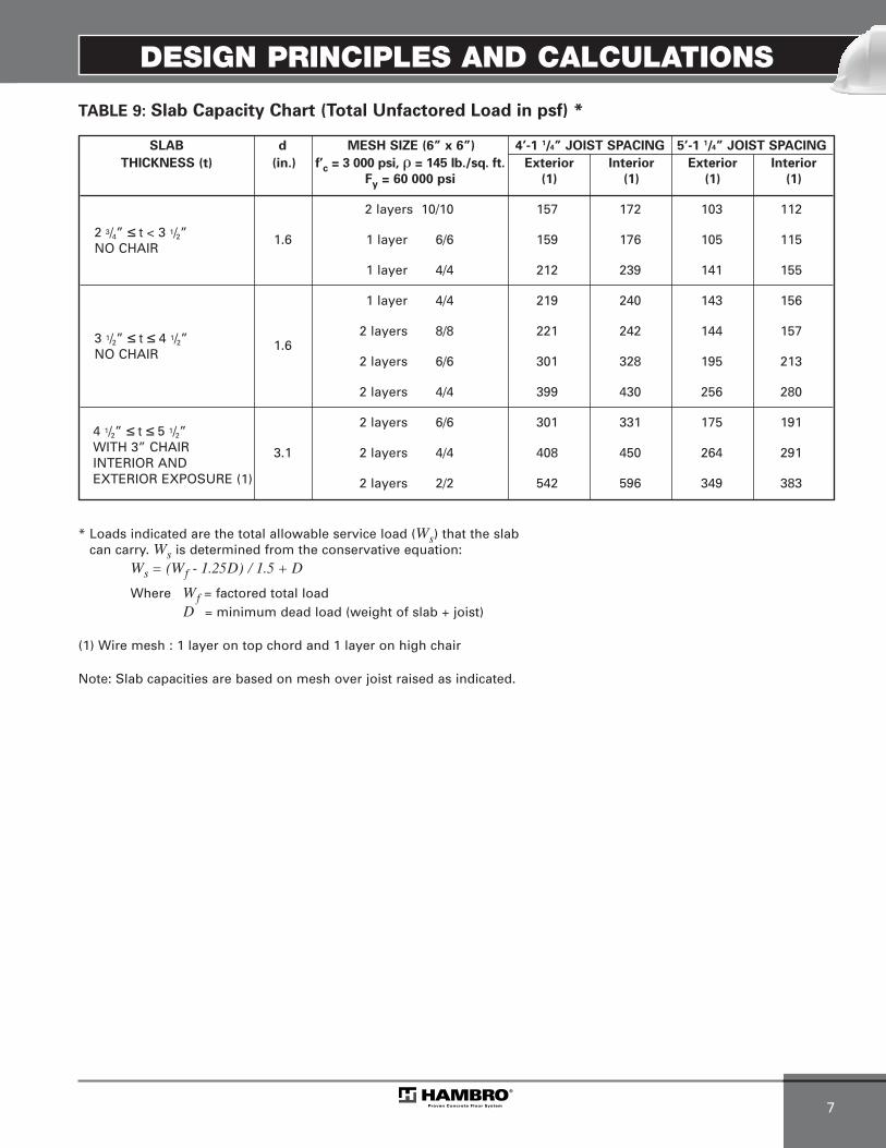
SLAB d MESH SIZE (6” x 6”) 4’-1 1/4” JOIST SPACING 5’-1 1/4” JOIST SPACING
THICKNESS (t) (in.) f’c = 3 000 psi, � = 145 lb./sq. ft. Exterior Interior Exterior Interior
Fy = 60 000 psi (1) (1) (1) (1)
2 layers 10/10 157 172 103 112
2 3/4” ≤ t < 3 1/2” 1.6 1 layer 6/6 159 176 105 115NO CHAIR
1 layer 4/4 212 239 141 155
1 layer 4/4 219 240 143 156
3 1/2” ≤ t ≤ 4 1/2” 1.62 layers 8/8 221 242 144 157
NO CHAIR 2 layers 6/6 301 328 195 213
2 layers 4/4 399 430 256 280
2 layers 6/6 301 331 175 191
3.1 2 layers 4/4 408 450 264 291
2 layers 2/2 542 596 349 383
TABLE 9: Slab Capacity Chart (Total Unfactored Load in psf) *
* Loads indicated are the total allowable service load (Ws) that the slabcan carry. Ws is determined from the conservative equation:
Ws = (Wf - 1.25D) / 1.5 + D
Where Wf = factored total loadD = minimum dead load (weight of slab + joist)
(1) Wire mesh : 1 layer on top chord and 1 layer on high chair
Note: Slab capacities are based on mesh over joist raised as indicated.
4 1/2” ≤ t ≤ 5 1/2”WITH 3” CHAIRINTERIOR ANDEXTERIOR EXPOSURE (1)
MEP-Technical Manual CDN 0408.qxd 08/04/2009 18:06 Page 17

DESIGN PRINCIPLES AND CALCULATIONS
8
4.2 NON-COMPOSITE DESIGN
The top chord must be verified for the loads applied at the non-composite stage. From the previous example, wehave the following results:
1- Factored Loading• Dead load:70 mm slab: 1.65 kN/m2
Formwork and joist: 0.24 kN/m2
1.89 kN/m2 x 1.25 = 2.36 kPa
• Live load: Construction live load: 0.95* kN/m2 x 1.5 = 1.43 kPa
Total factored load = 3.79 kPa
* Reduces beyond 7 620 mm span at a rate of0.05 kN/m2 each 760 mm of span.
2- Factored moment resistanceMr nc = Crd or Trd
i.e. Wnc L2 = Crd or Trd, whichever is the lesser
Wnc = 3.79 x joist spacing = kN/mL = clear span + 100 mmC = area of top chord (mm2) x factored
compressive resistance (MPa)T = area of bottom chord (mm2) x factored
tensile resistance (MPa)d = effective lever arm (m)
= (D + 2 mm - y) /1 000
From the above formula, the maximum “limiting span”may be computed for the non-composite (constructionstage) condition. For spans beyond this value, the topchord must be strengthened or joist propped.Strengthening of the top chord, when required, is usuallyaccomplished by installing one or two rods in the curva-tures of the “S” part of the top chord.
The bottom chord is sized for the total factored load whichis more critical than the construction load.
Hambro top chord properties are provided to assist you in computing the non-composite joist capacities.
4.2.1 TOP CHORD PROPERTIES - D500TM
METRIC
t = 2.3 mm
Anet* = 361 mm2
Ix = 2.74 x 105 mm4
Top Chord Fy = 350 MPa
Bottom Chord Fy = 380 MPa
IMPERIAL
t = 0.090 in.
Anet* = 0.560 in.2
Ix = 0.658 in.4
Top Chord Fy = 50 ksi
Bottom Chord Fy = 55 ksi
Anet* = Effective area according to CAN3-S136-01
8
Fig. 8
N.A. of top chordCr
Tr
2D
Y
d
Fig. 9
X X
17 mm(0.68”)
t
Y
2 m
m(0
.08”
)
Y
MEP-Technical Manual CDN 0408.qxd 08/04/2009 18:06 Page 18
DESIGN PRINCIPLES AND CALCULATIONS
9
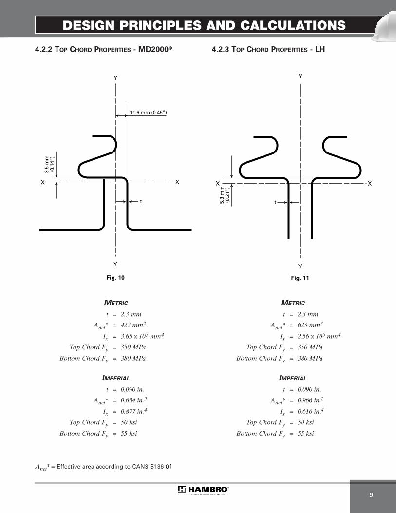
4.2.2 TOP CHORD PROPERTIES - MD2000®
METRIC
t = 2.3 mm
Anet* = 422 mm2
Ix = 3.65 x 105 mm4
Top Chord Fy = 350 MPa
Bottom Chord Fy = 380 MPa
IMPERIAL
t = 0.090 in.
Anet* = 0.654 in.2
Ix = 0.877 in.4
Top Chord Fy = 50 ksi
Bottom Chord Fy = 55 ksi
Anet* = Effective area according to CAN3-S136-01
4.2.3 TOP CHORD PROPERTIES - LH
METRIC
t = 2.3 mm
Anet* = 623 mm2
Ix = 2.56 x 105 mm4
Top Chord Fy = 350 MPa
Bottom Chord Fy = 380 MPa
IMPERIAL
t = 0.090 in.
Anet* = 0.966 in.2
Ix = 0.616 in.4
Top Chord Fy = 50 ksi
Bottom Chord Fy = 55 ksi
Fig. 10
X X
11.6 mm (0.45”)
t
Y
Y
3.5
mm
(0.1
4”)
Fig. 11
X X
t
Y
5.3
mm
(0.2
1”)
Y
MEP-Technical Manual CDN 0408.qxd 08/04/2009 18:06 Page 19

DESIGN PRINCIPLES AND CALCULATIONS
10
4.3 COMPOSITE DESIGN
4.3.1 FLEXURE DESIGN
In the past, conventional analysis of composite beamsections has been linearly elastic. Concrete and steelstresses have been determined by transforming thecomposite section to a section of one material, usuallysteel, from which stresses are then determined with thefamiliar formula, f = My/I, and then compared to somelimiting values which have been set to ensure an adequatelevel of safety. Although this procedure is familiar to mostengineers, it does not predict the level of safety with asmuch accuracy as does an ultimate strength approachwhich is based on the actual failure strengths of the component materials.
It is now known that the flexural behavior at “ultimate”failure stages of composite concrete/steel beams and joistsis similar to that of reinforced concrete beams - the elasticneutral axis begins to rise under increasing load as thecomponent materials are stressed into their inelasticranges. The typical stress-strain characteristics of theconcrete and steel components are shown in fig. 12.
The various loading stages of the Hambro composite joistare indicated in fig. 13. As load is first applied to thecomposite joist, the strains are linear. The “elastic” neutralaxis, concrete and steel stresses can be predicted from theconventional transformed area method. Generally speak-ing, the Hambro composite joist behaves in this “elastic”manner when subjected to the total working loads. Withincreasing load, failure always begins initially with yieldingof the bottom chord. In (a), all of the bottom chord has justreached the yield stress, Fy. The maximum concretestrains will likely have just progressed into the inelasticconcrete range, but the maximum concrete stress will stillbe less than �1f’c.
With a further increase in load, large inelastic strains occurin the bottom chord and the ultimate tensile force, Tu ,remains equal to As Fy. The strain neutral axis rises, asdoes the centroid of the compresssion force. Part (b)depicts the stage when the maximum concrete stress hasjust reached �1f’c. At this stage, the ultimate resistingmoment has increased slightly due to a small increase inIever arm.
Fig. 12
Concrete and Steel Stress - Strain Curves
Steel strain
Fu
Ey
Fy
Ste
el s
tres
s
Elas
ticra
nge
Concrete strain
f’c
Con
cret
e st
ress
Inel
astic
rang
eEl
astic
rang
eIn
elas
ticra
nge
MEP-Technical Manual CDN 0408.qxd 08/04/2009 18:06 Page 20

DESIGN PRINCIPLES AND CALCULATIONS
11
4.3.2 VARIOUS FLEXURE FAILURE STAGES
Upon additional load application, the steel and concretestrains progress further into their inelastic ranges. Thestrain neutral axis continues to rise and the lever armcontinues to increase as the centroid of compression forcecontinues to rise. In (c), final failure occurs with crushing ofthe upper concrete fibres. At this point, the maximum feverarm e’, has been reached. In load capacity calculations, thesimplified concrete stress block as shown in (c) is univer-sally used.
According to CAN3-S16.1-M01 (cl.17.9.3) and CSA A23.3-04(cl.10.1.7), the factored resisting moment of the compositesection is given by:
Mrc = øs As Fye’ = Tre’
Where e’ = d + slab thickness – a/2 – yd = joist deptha = Tr / �1 øc f’cbeøs = steel performance factor = 0.90As= area of bottom chordy = neutral axis of bottom chord
Fy = yield point of steel
øc = concrete performance factor = 0.65
f’c = concrete compressive strengthbe = effective width of concrete top flange
= the lesser of - joist spacing, or - span /4.
Note: To determine the total allowable service load Ws(see load tables), we convert the factored momentinto a factored linear loading.
And
Where D = weight of (slab + joist)
Mf = Wf L2(single span moment)
8
Ws = (Wf - 1.25 D) + D1.5
Wf = 8 Mf
L2
Fig. 13
Jois
t dep
th “
d” Strain line
�1f’c
Cf a
Ey
�1øcf’c
C
t
Tu = AsFy
(a)Initial steel yield
e’
f’c
Cu
Tu = AsFy
(c)Ultimate stage
�1f’c
Ey
Tu = AsFy
(b)Secondary yield stages
Simplifiedconcrete
stress block
Elasticstrain Inelastic strain
Elasticstrain Inelastic strain
MEP-Technical Manual CDN 0408.qxd 08/04/2009 18:06 Page 21
DESIGN PRINCIPLES AND CALCULATIONS
12
4.4 INTERFACE SHEAR
The Hambro joist comprises a composite concrete slab-steel joist system with composite action achieved by theshear connection developed by two means:
(i) by anchorage provided at the joist ends bymeans of a steel angle which acts both as abearing shoe and as anchorage for the enddiagonal, thereby producing horizontal bearingforces. This horizontal force is closely asso-ciated with the concrete strength and the verti-cal size of the steel angle plate on the shoe.
(ii) by bond or friction between the partiallyembedded specially profiled top chord.
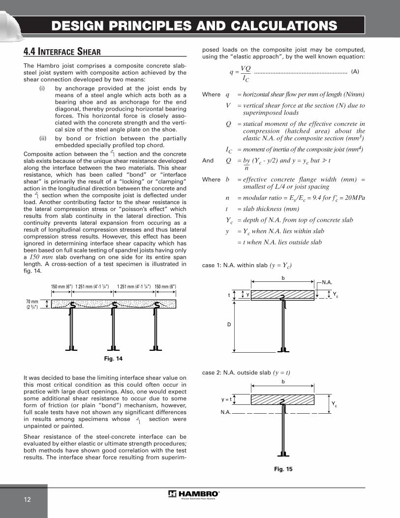
Composite action between the section and the concreteslab exists because of the unique shear resistance developedalong the interface between the two materials. This shearresistance, which has been called “bond” or “interfaceshear” is primarily the result of a “locking” or “clamping”action in the longitudinal direction between the concrete andthe section when the composite joist is deflected underload. Another contributing factor to the shear resistance isthe lateral compression stress or “poisson’s effect” whichresults from slab continuity in the lateral direction. Thiscontinuity prevents lateral expansion from occuring as aresult of longitudinal compression stresses and thus lateralcompression stress results. However, this effect has beenignored in determining interface shear capacity which has been based on full scale testing of spandrel joists having only a 150 mm slab overhang on one side for its entire spanlength. A cross-section of a test specimen is illustrated infig. 14.
It was decided to base the limiting interface shear value onthis most critical condition as this could often occur inpractice with large duct openings. Also, one would expectsome additional shear resistance to occur due to someform of friction (or plain “bond”) mechanism, however,full scale tests have not shown any significant differencesin results among specimens whose section wereunpainted or painted.
Shear resistance of the steel-concrete interface can be evaluated by either elastic or ultimate strength procedures;both methods have shown good correlation with the testresults. The interface shear force resulting from superim-
posed loads on the composite joist may be computed,using the “elastic approach”, by the well known equation:
......................................................... (A)
Where q = horizontal shear flow per mm of length (N/mm)
V = vertical shear force at the section (N) due tosuperimposed loads
Q = statical moment of the effective concrete incompression (hatched area) about theelastic N.A. of the composite section (mm3)
IC = moment of inertia of the composite joist (mm4)
And Q = by (Yc - y/2) and y = yc but � t
Where b = effective concrete flange width (mm) =smallest of L/4 or joist spacing
n = modular ratio = Es /Ec = 9.4 for f’c = 20MPa
t = slab thickness (mm)
Yc = depth of N.A. from top of concrete slab
y = Yc when N.A. lies within slab
= t when N.A. lies outside slab
case 1: N.A. within slab (y = Yc)
Fig. 14
150 mm (6”) 150 mm (6”)1 251 mm (4’-1 1/4”) 1 251 mm (4’-1 1/4”)
70 mm(2 3/4”)
Fig. 15
t
D
y Yc
N.A.b
y = tYc
N.A.
b
q = VQIC
n
case 2: N.A. outside slab (y = t)
MEP-Technical Manual CDN 0408.qxd 08/04/2009 18:06 Page 22

DESIGN PRINCIPLES AND CALCULATIONS
13
For a uniformly loaded joist, the average interface shear s,at ultimate load when calculated by ultimate strengthprinciples, would be:
......................................................... (B)
and would represent the average shear force, per unitlength, between the points of zero and maximum moment.Some modification to this formula would occur when thestrain neutral axis at failure would be located withinthe section. As this modification is slight and would onlyoccur with bottom chord areas greater that 1 185 mm2,it is neglected.
The following compares the elastic and ultimate approaches:
Since Mu = Tudu equation (B) can be rewritten:
......................................................... (C)
Also, for a uniformly distributed load,
......................................................... (D)
Subscipts u, are added to equation (A) to represent thearbitrary “q” force at failure:
......................................................... (E)
Combining (C) and (E) results in:
.............................................. (F)
and, substituting (D) into equation (F),
...................................................... (G)
The value Ic /Qdu has been calculated for the variousHambro composite joist sizes. It is constant, and = 1.1.Substituting this in (G), gives:
This verifies that q and s are closely related and that the interface shear force does, in fact, vary from a maximum atzero moment (maximum vertical shear) to a minimum atmaximum moment (zero vertical shear).
The more recent full testing programs have consistently established a failure value for the horizontal bearing forces and the friction between steel and concrete. An additional contributing factor is a hole in the section at each 178 mmon the length.
(i) Horizontal bearing forces
The test has defined an ultimate value for theend bearing shoe Bu = 222 kN for a concretestrength = 20 MPa
(ii) Friction between steel and top chord
The failure value for the interface shear qu = 36.9 N/mm. This is sometimes convertedto “bond stress” u = q / embedded S perimeter = q /178 mm. Hence, the ultimate “bond stress” u = 36.9 / 178 = 207 kPa.
The safety limiting interface shear is defined byusing a safety factor of 2 on point (i) and (ii).
s = 2TuL
s = 2MuduL
Mu = VuL
4
qu = VuQ
Ic
qu = duL x VuQ
2Mu Ics
qu = 2Qdu
Ics
qu = 1.82 s
MEP-Technical Manual CDN 0408.qxd 08/04/2009 18:06 Page 23

DESIGN PRINCIPLES AND CALCULATIONS
14
4.5 WEB DESIGN
4.5.1 VERTICAL SHEAR
The web of the steel joist is designed according to CAN3-S16.1-M01. Clause 17.3.2 requires the web system to be proportioned to carry the total vertical shear Vf . The loading applied to the joist is as follows:
a) A uniformly distributed load equal to the total dead and live loads.
b) An unbalanced load with 100% of the total dead loadand live loads on any continuous portion of the joist and25% of the total dead and live loads on the remainder toproduce the most critical effect on any component.
c) A factored concentrated load of 13.5 kN (3.0 kips)applied at any panel point.
The above loadings need not be applied simultaneously.
These assumptions result in calculated bar forces whichhave been shown by test to be as much as 15% higher thanthe actual values because the slab, acting compositely withthe ~ section, is stiff enough to transmit some load direct-ly to the support. This is particularly true for web membersat the joist ends – those which are subjected to the highestvertical shear. However, the slab shear contribution isdisregarded when designing the webs.
Due consideration of the total end reaction being concen-trated at the shoe shall be taken by the specifying engineeror architect in the design of supporting members.
4.5.2. EFFECTIVE LENGTH
OF COMPRESSION DIAGONAL
The webs are dimensioned using cl. 13.2 for tension mem-bers and cl. 13.3 for compression member. The effectivelength of web member KL is taken as 1.0 times the distancebetween the intersection of the axis of the web and thechords. Except for continuous web member.
Note: The web members are sized for the loading specifiedincluding concentrated loads where applicable.Furthermore, the webs are designed according to the latest recommendations of the Canadian Institute ofSteel Construction (CISC).
Fig. 16
D500TM and MD2000® Geometry
R
d
(Clear span - 12.5 mm or 1/2”)
H1
Vf1 Vf2 Vf3 Vf4 Vf5 Vf
W1 W2 WC WC WC WC
C 1
T1
C 2
T2
C 3
T3
C 4
T4
C 5
T5
MEP-Technical Manual CDN 0408.qxd 08/04/2009 18:06 Page 24
DESIGN PRINCIPLES AND CALCULATIONS
15
4.6 DIAPHRAGM DESIGN
4.6.1 THE HAMBRO SLAB AS A DIAPHRAGM
With the increasing use of the Hambro system for floor of buildings in earthquake prone areas such as Anchorage, Los Angeles, Vancouver, Montreal and Quebec City or in hurricane prone areas such as Florida as well as for multi-storey buildings where shear transfer could occur at somelevel of the building due to the reduction of the floor plan,it is important to develop an understanding of how theslabs will be able to transmit horizontal loads while beingpart of the Hambro floor system.
The floor slab, part of the Hambro system, must be designedby the project structural engineer as a diaphragm to resist horizontal loads and transmit them to the vertical bracingsystem.
Any diaphragm has the following limit states:
1) Shear strength between the supports
2) Out of plane buckling
3) In plane deflection of the diaphragm
4) Shear transmission at the supports
A diaphragm works as the web of a beam spanningbetween or extending beyond the supports. In the case ofa floor slab, the slab is the web of the beam spanningbetween or extending beyond the vertical elementsdesigned to transmit to the foundations the horizontalloads produced by earthquake or wind.
We will use a simple example of wind load acting on adiaphragm part of a horizontal beam forming a single spanbetween end walls. The structural engineer responsible forthe design of the building shall establish the horizontalloads that must be resisted at each floor of the building forthe wind and earthquake conditions prevailing at the build-ing location. The structural engineer must also identify thevertical elements that will transmit the horizontal loads tothe foundations in order to calculate the shear that must beresisted by the floor slab.
4.6.2 SHEAR STRENGTH BETWEEN SUPPORTS
A series of fourteen specimens of concrete slabs, part of aHambro floor system, were tested in the laboratories ofCarleton University in Ottawa. The purpose of the tests wasto identify the variables affecting the in plane shear strengthof the concrete slab reinforced with welded wire mesh.
The specimens were made of slabs with a concrete thick-ness of 63 mm (2.5”) or 70 mm (2.75”) forming a beam witha span of 610 mm (24”) and a depth of 610 mm (24”). Thisbeam was loaded with two equal concentrated loads at152 mm (6”) from the supports. The other variables were:
1) The size of the wire mesh
2) The presence or absence of the Hambro joist embed-ded top chord parallel to the load in the shear zone
3) The concrete strength
It was found that the shear resistance of the slab is mini-mized when the shear stress is parallel to the Hambro joistembedded top chord. A conservative assumption could bemade that the concrete confined steel wire mesh is the
only element that will transmit the shear load over theembedded top chord.
In the following example of the design procedure, we willtake into account that the steel of the wire mesh is alreadyunder tension stresses produced by the continuity of theslab over the Hambro joist, and that the remainingcapacity of the steel wire mesh will be the limiting factorfor the shear strength of the slab.
The largest bending moment is over the embedded top chord and is calculated for one meter width. In usingthe example from section 4.1.5 page 5, the non factoredmoment is:
Dead load*: Mfd = 3KPa x (1.2m)2 / 10 = 0.43 kN•mLive load*: MfL = 2KPa x (1.2m)2 / 10 = 0.29 kN•m.
1) Loads
Factored dead load: 1.25 x 3.0 = 3.75 kPaFactored live load: 1.50 x 2.0 = 3.00 kPaFactored total load: 6.75 kPa
And thus the factored live load accounts for 44% of the factored total load.
2) Bending moment in the slab between joists due to gravity loads
The smallest lever arm between the compression concrete surface and the tension steel of the wire mesh is also over the embedded top chord. This dimension allows us tocalculate the factored bending capacity of the slab to beMr = 1.61 kN•m*.
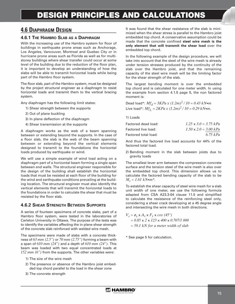
To establish the shear capacity of steel wire mesh for a slabunit width of one meter, we use the following formula adapted from CSA A23.3-04 clause 11.5 and simplified to calculate the resistance of the reinforcing steel only, considering a shear crack developing at a 45 degree angleand intersecting the wire mesh in both directions.
Vr = øs x As x Fy x cos (45°) = 0.85 x 2 x 123 x 400 x 0.707/1 000= 59.1 kN for a meter width of slab
* See page 5 for calculation.
MEP-Technical Manual CDN 0408.qxd 08/04/2009 18:06 Page 25

DESIGN PRINCIPLES AND CALCULATIONS
16
Wind load = 1.2 kN/m2
L = 35 500 mm
B = 18 300 mm
FirstHambroJoist
Fig. 17
DESIGN EXAMPLE METRIC
From figure 17 we can establish the horizontal shear thatthe floor diaphragm will have to resist in order to transfer the horizontal load from the walls facing the wind to the perpendicular walls where a vertical bracing system willbring that load down to the foundation.
Total wind pressure load from leeward and windward faces: 1.2 kPaStorey height: 3.7 mSpan of the beam with the floor slab acting as the web: 35.5 mLength of the walls parallel to the horizontal force: 18.3 m
For the purpose of our example the factored wind load is the maximum horizontal load calculated according to the provisionsof the local building code, but earthquake load shall also be cal-culated by the structural design engineer of the project and themaximum of the two loads should be used in the calculation.
Vf = wf x span / 2 = 3.7 x 1.2 x 35.5 / 2 = 78.8 kN
In our example, the end reaction is distributed along the whole length of the end wall used to transfer the load, 18.3 m in our example.
Vf = 78.8 / 18.3= 4.3 kN for a meter width of slab
Considering the reduction factor from the National BuildingCode 2005 for the simultaneity of gravity live load and hori-zontal wind load for our example, the structural engineer ofthe project could verify the diaphragm capacity of the floorslab and it’s reinforcing by verifying that the moment andshear interaction formulas used below are less than unity:
Load Combinaison 1:
Doesn’t control
Load Combinaison 2:
(Controls)Load Combinaison 3:
These verifications indicate that the wire mesh imbeddedin the slab would provide enough shear strength totransfer those horizontal loads.
4.6.3 OUT OF PLANE BUCKLING
The floor slab, when submitted to a horizontal shear load,may tend to buckle out of plane like a sheet of paper beingtwisted. The minimum thickness of Hambro concrete slabof 65 mm (2 1/2”) is properly held in place by the Hambrojoists spaced at a maximum 1 555 mm (5’-1 1/4”) and whoare attached at their ends to prevent vertical movement,so the buckling length of the slab itself will be limited to thespacing of the joist and the buckling of a floor will normal-ly not be a factor in the design of the slab as a diaphragm.
4.6.4 IN PLANE DEFLECTION OF THE DIAPHRAGM
As for every slab used as a diaphragm, the deflection of thefloor as a horizontal member between the supports pro-vided by the vertical bracing system shall be investigatedby the structural engineer of the building to verify that thehorizontal deflection remains within the allowed limits.
4.6.5 SHEAR TRANSMISSION TO
THE VERTICAL BRACING SYSTEM
The structural engineer of the project shall design and indi-cate on his drawings proper methods and/or reinforcing toattach the slab to the vertical bracing system over such alength as to prevent local overstress of the slab capacity totransfer shear.
1.25 x Mf d + 1.5 x Mf LMr Mr
1.25 x Mf d + 1.5 x Mf L + 0.4 x Vf ≤ 1Mr Mr Vr
1.25 x Mf d + 0.5 x Mf L + 1.4 x Vf ≤ 1Mr Mr Vr
(1.25 x 0.43) + (1.5 x 0.29 ) + 0.4 x 4.3 = 0.64 ≤ 1 OK1.61 1.61 59.1
(1.25 x 0.43) + (0.5 x 0.29) + 1.4 x 4.3 = 0.53 ≤ 1 OK1.61 1.61 59.1
MEP-Technical Manual CDN 0408.qxd 08/04/2009 18:06 Page 26

DESIGN PRINCIPLES AND CALCULATIONS
17
4.7 LATERAL LOAD DISTRIBUTIONLine loads are often encountered in construction, i.e. a concrete block wall or even a load bearing concrete blockwall. It is always desirable to have a floor system that isstiff enough to allow these line loads to be distributed toadjacent joists rather than be carried by the joist thathappens to be directly under it.
The Hambro Composite Floor System provides thedesigner with this desirable feature.
This was conclusively proven by randomly selecting asample of five similar adjacent joists in a bay in an apart-ment structure and line loading the centre one.
The joists were 300 mm (12”) deep, had a clear span of 6 500 mm (21’-4”) and a 75 mm (3”) thick slab. Theloads were applied using brick pallets. At every load stage,steel strains as well as deflections were measured.
The distribution of load to each of the five joists can be determined by comparing deflections or stresses at similarlocations in the five joists under investigation.
Tests have demonstrated that for a line load applied to a typical joist in a bay, the actual distribution of load to thatjoist is approximately 40% of the applied load. The distri-bution of load to the adjacent joist on either side is approx-imately 21% of the applied load and to the next adjacentjoist approximately 9% of the applied load.
MEP-Technical Manual CDN 0408.qxd 08/04/2009 18:06 Page 27
DESIGN PRINCIPLES AND CALCULATIONS
18
4.8 MINI-JOISTS
4.8.1 H SERIES
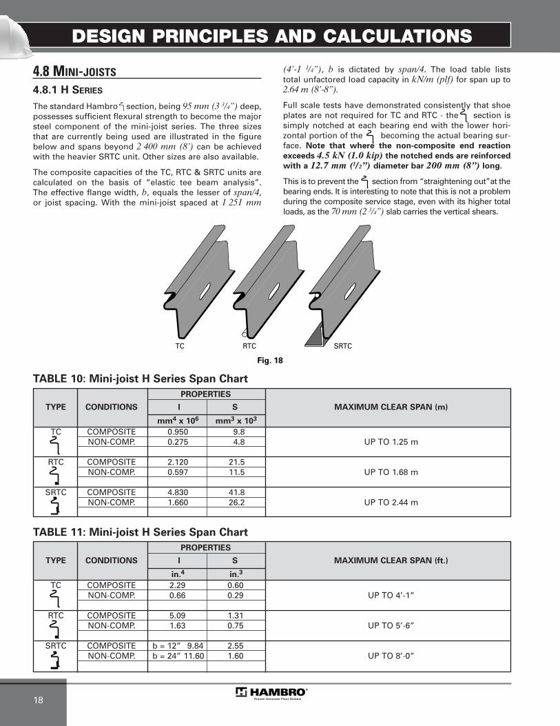
The standard Hambro section, being 95 mm (3 3/4”) deep,possesses sufficient flexural strength to become the majorsteel component of the mini-joist series. The three sizesthat are currently being used are illustrated in the figurebelow and spans beyond 2 400 mm (8’) can be achievedwith the heavier SRTC unit. Other sizes are also available.
The composite capacities of the TC, RTC & SRTC units are calculated on the basis of “elastic tee beam analysis”. The effective flange width, b, equals the lesser of span/4, or joist spacing. With the mini-joist spaced at 1 251 mm
(4’-1 1/4”), b is dictated by span/4. The load table lists total unfactored load capacity in kN/m (plf) for span up to 2.64 m (8’-8”).
Full scale tests have demonstrated consistently that shoeplates are not required for TC and RTC - the section issimply notched at each bearing end with the lower hori-zontal portion of the becoming the actual bearing sur-face. Note that where the non-composite end reaction
exceeds 4.5 kN (1.0 kip) the notched ends are reinforced
with a 12.7 mm (1/2”) diameter bar 200 mm (8”) long.
This is to prevent the section from “straightening out”at thebearing ends. It is interesting to note that this is not a problemduring the composite service stage, even with its higher totalloads, as the 70 mm (2 3/4”) slab carries the vertical shears.
TC RTC SRTC
Fig. 18
PROPERTIES
TYPE CONDITIONS I S MAXIMUM CLEAR SPAN (m)
mm4 x 106 mm3 x 103
TC COMPOSITE 0.950 9.8NON-COMP. 0.275 4.8 UP TO 1.25 m
RTC COMPOSITE 2.120 21.5NON-COMP. 0.597 11.5 UP TO 1.68 m
SRTC COMPOSITE 4.830 41.8NON-COMP. 1.660 26.2 UP TO 2.44 m
PROPERTIES
TYPE CONDITIONS I S MAXIMUM CLEAR SPAN (ft.)
in.4 in.3
TC COMPOSITE 2.29 0.60NON-COMP. 0.66 0.29 UP TO 4’-1”
RTC COMPOSITE 5.09 1.31NON-COMP. 1.63 0.75 UP TO 5’-6”
SRTC COMPOSITE b = 12” 9.84 2.55NON-COMP. b = 24” 11.60 1.60 UP TO 8’-0”
TABLE 10: Mini-joist H Series Span Chart
TABLE 11: Mini-joist H Series Span Chart
MEP-Technical Manual CDN 0408.qxd 08/04/2009 18:06 Page 28
DESIGN PRINCIPLES AND CALCULATIONS
19
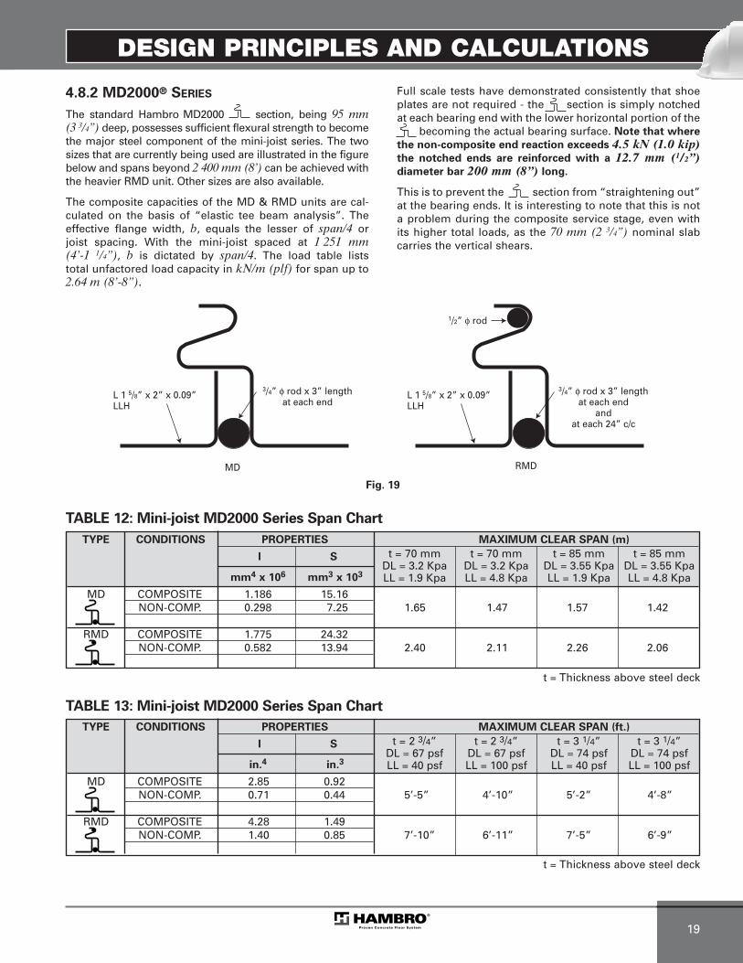
4.8.2 MD2000® SERIES
The standard Hambro MD2000 section, being 95 mm (3 3/4”) deep, possesses sufficient flexural strength to becomethe major steel component of the mini-joist series. The twosizes that are currently being used are illustrated in the figurebelow and spans beyond 2 400 mm (8’) can be achieved withthe heavier RMD unit. Other sizes are also available.
The composite capacities of the MD & RMD units are cal-culated on the basis of “elastic tee beam analysis”. Theeffective flange width, b, equals the lesser of span/4 or joist spacing. With the mini-joist spaced at 1 251 mm(4’-1 1/4”), b is dictated by span/4. The load table lists total unfactored load capacity in kN/m (plf) for span up to2.64 m (8’-8”).
Full scale tests have demonstrated consistently that shoeplates are not required - the section is simply notchedat each bearing end with the lower horizontal portion of the
becoming the actual bearing surface. Note that where
the non-composite end reaction exceeds 4.5 kN (1.0 kip)the notched ends are reinforced with a 12.7 mm (1/2”)diameter bar 200 mm (8”) long.
This is to prevent the section from “straightening out”at the bearing ends. It is interesting to note that this is nota problem during the composite service stage, even withits higher total loads, as the 70 mm (2 3/4”) nominal slabcarries the vertical shears.
MD
L 1 5/8” x 2” x 0.09”LLH
3/4” φ rod x 3” lengthat each end
RMD
Fig. 19
L 1 5/8” x 2” x 0.09”LLH
1/2” φ rod
3/4” φ rod x 3” lengthat each end
andat each 24” c/c
TABLE 12: Mini-joist MD2000 Series Span Chart
TABLE 13: Mini-joist MD2000 Series Span Chart
TYPE CONDITIONS PROPERTIES MAXIMUM CLEAR SPAN (m)
I S
mm4 x 106 mm3 x 103
MD COMPOSITE 1.186 15.16NON-COMP. 0.298 7.25 1.65 1.47 1.57 1.42
RMD COMPOSITE 1.775 24.32NON-COMP. 0.582 13.94 2.40 2.11 2.26 2.06
TYPE CONDITIONS PROPERTIES MAXIMUM CLEAR SPAN (ft.)
I S
in.4 in.3
MD COMPOSITE 2.85 0.92NON-COMP. 0.71 0.44 5’-5” 4’-10” 5’-2” 4’-8”
RMD COMPOSITE 4.28 1.49NON-COMP. 1.40 0.85 7’-10” 6’-11” 7’-5” 6’-9”
t = 70 mm t = 70 mm t = 85 mm t = 85 mmDL = 3.2 Kpa DL = 3.2 Kpa DL = 3.55 Kpa DL = 3.55 KpaLL = 1.9 Kpa LL = 4.8 Kpa LL = 1.9 Kpa LL = 4.8 Kpa
t = 2 3/4” t = 2 3/4” t = 3 1/4” t = 3 1/4”DL = 67 psf DL = 67 psf DL = 74 psf DL = 74 psfLL = 40 psf LL = 100 psf LL = 40 psf LL = 100 psf
t = Thickness above steel deck
t = Thickness above steel deck
MEP-Technical Manual CDN 0408.qxd 08/04/2009 18:06 Page 29

MEP-Technical Manual CDN 0408.qxd 08/04/2009 18:06 Page 30

PRODUCT INFORMATION
1
5. PRODUCT INFORMATION
5.1 D500TM (H SERIES)5.1.1 DESCRIPTION
Hambro H Series features a top chord made of oneHambro section, an open web of mild steel rods and widerange of bottom chord angles.
5.1.2 MATERIALS
The Hambro top chord acts as a continuous shear connec-tor. Bottom chord angles and web members are hot or coldrolled sections, minimum yield Fy = 380 MPa (55 ksi) and 350 MPa (50 ksi) for rods.
5.1.3 WEB GEOMETRY
See below.
5.1.4 JOIST SPACING
1 251 mm (4’-1 1/4”), typical unless noted.
5.1.5 SPAN AND DEPTH
Span: Up to 13 100 mm (43’-0”).
Depth: Between 200 mm (8”) and 600 mm (24”).
5.1.6 SLAB DESIGN
The minimum slab thickness is 65 mm (2 1/2”) and the slabcapacity chart tables 8 and 9 on page 19 and 20, shows thetotal allowable load (including the dead load of the slab)based on 20 MPa (3000 psi) concrete.
5.1.7 ROLLBAR®
Standard 1 251 mm (4’-1 1/4”).Non standard available for specific case.
5.1.8 FORMS
Standard 12.7 mm (1/2”) or 9.5 mm (3/8”) plywood sheets, 1 220 mm x 2 440 mm (4’ x 8’).
5.1.9 INSTALLATION
See installation Manual for the Hambro D500 Composite Floor System and drawing ED D500 provided for each spe-cific project.
5.1.10 TYPICAL DETAILS
See typical details section page 1 to 11.
R
d
(Clear span - 12.5 mm or 1/2”)
P1t P P P P
P P P
W1 W2 WC WC
“n” Continuous panels
WC WC
P1b P2b
WEB GEOMETRY (mm)
NOM. DEPTH “d” P1t P1b P2b P
200, 250 152 to 305 152 to 406 305 508
300 254 to 406 254 to 533 406 610
350, 400 381 to 610 381 to 813 508 610
450, 500, 550, 600 483 to 610 483 to 813 610 610
WEB GEOMETRY (in.)
NOM. DEPTH “d” P1t P1b P2b P
8, 10 6 to 12 6 to 16 12 20
12 10 to 16 10 to 21 16 24
14, 16 15 to 24 15 to 32 20 24
18, 20, 22, 24 19 to 24 19 to 32 24 24
Fig. 20
D500 and MD2000® Web Geometry
MEP-Technical Manual CDN 0408.qxd 08/04/2009 18:06 Page 31

PRODUCT INFORMATION
2
5.2 MD2000® SERIES
5.2.1 DESCRIPTION
Hambro MD2000 Series features a top chord made of 2 pieces welded together in order to receive the metal deckeach side. The open web is made with mild steel rods and a wide range of bottom chord. The steel deck is used as formwork only during pouring.
5.2.2 MATERIALS
The Hambro top chord acts as a continuous shear connec-tor. Bottom chord angles and web members are hot or coldrolled sections, minimum yield Fy = 380 MPa (55 ksi) and 350 MPa (50 ksi) for rods.
5.2.3 WEB GEOMETRY
The web geometry is exactly the same of D500TM
presented in page 33.
5.2.4 JOIST SPACING
Between 300 mm (1’-0”) and 1 450 mm (4’-9”) accordingto the steel deck capacity in single span. The standardspacing is 1 220 mm (4’-0”).
5.2.5 SPAN AND DEPTH
Span: Up to 13 100 mm (43’-0”)Depth: Between 200 mm (8”) and 600 mm (24”)
5.2.6 SLAB DESIGN
The minimum “TOTAL SLAB THICKNESS” is 110 mm(4 1/4”) including the steel deck. See figure 21 for moreinformation.
5.2.7 STEEL DECK
The steel deck used is P-3606, 22 GA (0.76 mm). The depth is 38 mm (1 1/2”). The deck must be designed in single span(spacing between joist). For more information, see theCanam brochure about it. The deck must be connected onthe MD2000 top chord by welding or screwing.
5.2.8 INSTALLATION
Installation shall be in accordance with the manufacturer’s recommendations and the erection drawings.
5.2.9 PERMANENT BRIDGING
Bridging must be installed as specified on erectiondrawings.
5.2.10 TYPICAL DETAILS
See typical details section page 13 to 22.
Fig. 21
Sla
bTh
ickn
ess
MD
2000
Joi
stD
epth
Top of Slab
38 mm (1 1/2”) Steel Deck(22 GA. MIN.)
38 m
m
(1 1 /2”
) To
tal s
lab
thic
knes
s
Total slab thickness = Slab thickness + 38 mm (1 1/2”)Total slab thickness ≥ 110 mm (4 1/4”)
Slab thickness ≥ 70 mm (2 3/4”)
MEP-Technical Manual CDN 0408.qxd 08/04/2009 18:06 Page 32

PRODUCT INFORMATION
3
5.3 DTC (LH SERIES)5.3.1 DESCRIPTION
This series features a top chord made of two Hambrosections, an open web of light channels or angles and arange of heavier bottom chord angles.
Hambro composite long span floors provide greatereconomy for heavy service loads and longer spans withlive load deflections less than half those of conventionalsystems.
5.3.2 MATERIALS
The Hambro top chord acts as a continuous shear connec-tor. Bottom chord angles and web members are hot or coldrolled sections, minimum yield Fy = 380 MPa (55 ksi) and350 MPa (50 ksi) for rods.
5.3.3 WEB GEOMETRY
See below.
5.3.4 JOIST SPACING
Note the new standard spacing Hambro LH Series,1 285 mm (4’-2 5/8”) center to center, which is obtainedwhen using standard Rollbar® (1 251 mm (4’-1 1/4”)spacing plus 35 mm (1 3/8”) web thickness).
5.3.5 SPAN AND DEPTH
Span: Up to 16 155 mm (53’-0”).
Depth: Between 400 mm (16”) and 900 mm (36”).
5.3.6 SLAB DESIGN
The minimum slab thickness is 70 mm (2 3/4”) and the slabcapacity chart tables 8 and 9 on page 19 and 20 shows thetotal allowable load (including the dead load of the slab)based on 20 MPa (3 000 psi) concrete.
5.3.7 ROLLBAR
Standard 1 251 mm (4’-1 1/4”) roll bars are used to supportthe plywood forms.
5.3.8 FORMS
Regular 1 220 mm (4’-0”) plywood forms must be slit inhalf, 610 mm x 2 440 mm (2’ x 8’) panels, to allow insertionbetween the top chords. Normally 12.7 mm (1/2”) plywoodis used.
5.3.9 INSTALLATION
Installation shall be in accordance with the manufacturer’s recommendations. Particular attention should be paid tothe erection of the long span Hambro joists and bridgingmust be installed as specified on the Hambro drawing.
5.3.10 TYPICAL DETAILS
See typical details section page 23 to 27.
Fig. 22
DTC Web Geometry
P1
P1 Variable panel
(Clear span – 12 mm or 1/2”)“n” Continuous panels
Variable panel P
d
VAR1 VAR2610 mm 610 mm 610 mm
24” 24” 24”(P1 + VAR1) /2
d = Joist depth
P1 = d + 300 mm (12”) ≤ 1 170 mm (46”)
VAR1 = 0 to 150 mm (6”)
VAR2 = 150 mm (6”) to 610 mm (24”)
MEP-Technical Manual CDN 0408.qxd 08/04/2009 18:06 Page 33

MEP-Technical Manual CDN 0408.qxd 08/04/2009 18:06 Page 34

JOIST DEPTH SELECTION TABLES
1
6. JOIST DEPTH SELECTION TABLES
METRIC
6.1 GENERAL INFORMATION
6.1.1 JOIST DEPTH SELECTION TABLES
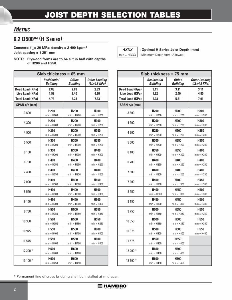
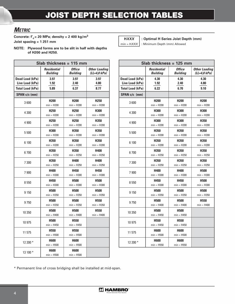
The following load tables give the optimized depth and the minimum depth for a specific span and a specific load following a certain slab thickness. Values indicated present a uniform load on all the length with a regular spacing and a f’c = 20 MPa. The regular spacing is 1 251 mm forD500TM (H Series), 1 285 mm for DTC (LH Series) and 1 220 mm for MD2000®.
The tables have been done for three types of loading with different thickness of concrete. The three types are resi-dential (live load = 1.92 kPa), office (live load = 2.4 kPa)and corridor or lobby (live load = 4.8 kPa). These threetypes are used in the tables as example. Any others typesof loading can be used for the Hambro design.
The tables have been created with a certain super-imposeddead load. Even if your superimposed dead load is a littlebit different, the optimal depth and the minimum depth inthe table will be right.
6.1.2 DEFLECTION CRITERIA
For all cases presented in the tables, deflection for live loaddoes not exceed L / 360.
6.1.3 JOIST IDENTIFICATION
The load tables are provided to aid engineers in selectingthe most optimal depth of joist for a particular slab thick-ness and a specific loading.
The engineer should specify the joist depth, slab thickness, the design loads, dead, live and total together with special point loads and line loads where applicable. Canam will provide composite joists designed to specifically meetthese requirements.
6.1.4 JOIST DESIGNATION
The joist designation should simply be the joist depthfollowed by the total allowable service load and live load inkN per meter applied on the joist.
Example: H250-7/3 for Hambro D500
Example: LH600-7/3 for Hambro DTC
Example: MDH300-7/3 for Hambro MD2000
6.1.5 EXAMPLE
Find the optimal depth and the minimum depth for the following office project with Hambro D500 (H Series).
Span: 9 750 mmSlab thickness: 100 mmJoist spacing: 1 251 mmConcrete strength: 20 MPaYield point of steel: 380 MPaConcrete density: 2 400 kg/m3
Dead load: 3.65 kN/m2
Joist: 0.12 kN/m2
Concrete: 2.32 kN/m2
Mechanical: 0.10 kN/m2
Ceiling (13 mm): 0.14 kN/m2
Partition: 0.96 kN/m2
TOTAL: 3.65 kN/m2
Live load (According to NBC): 2.40 kN/m2
Solution:
From tables, find slab thickness = 100 mm with a span = 9 750 mm
In the table, with dead load = 3.65 kN/m2 and live load = 2.40 kN/m2, we find:
Optimal depth = H500Minimum depth = H350
Then:
H500 means depth = 500 mmH350 means depth = 350 mm
MEP-Technical Manual CDN 0408.qxd 08/04/2009 18:06 Page 35
JOIST DEPTH SELECTION TABLES
2
METRIC
6.2 D500TM (H SERIES)
HXXX
min = HXXX
* Permanent line of cross bridging shall be installed at mid-span.
Concrete: f’c = 20 MPa; density = 2 400 kg/m3
Joist spacing = 1 251 mm
NOTE: Plywood forms are to be slit in half with depths
of H200 and H250.
: Optimal H Series Joist Depth (mm)
: Minimum Depth (mm) Allowed
Slab thickness = 75 mm
Residential Office Other LoadingBuilding Building (LL=4,8 KPa)
Dead Load (Kpa) 3.11 3.11 3.11Live Load (KPa) 1.92 2.40 4.80
Total Load (KPa) 5.03 5.51 7.91
SPAN c/c (mm)
3 600 H200 H200 H300min = H200 min = H200 min = H200
4 300 H200 H200 H300min = H200 min = H200 min = H200
4 900 H250 H300 H350min = H200 min = H200 min = H200
5 500 H300 H350 H350min = H200 min = H200 min = H200
6 100 H350 H350 H400min = H200 min = H200 min = H200
6 700 H400 H400 H400min = H250 min = H250 min = H250
7 300 H400 H400 H400min = H250 min = H250 min = H250
7 900 H400 H400 H450min = H300 min = H300 min = H300
8 550 H400 H450 H500min = H300 min = H300 min = H300
9 150 H450 H450 H500min = H300 min = H300 min = H300
9 750 H500 H550 H550min = H350 min = H350 min = H350
10 350 H500 H500 H550min = H350 min = H350 min = H350
10 975 H500 H500 H550min = H400 min = H400 min = H400
11 575 H550 H550min = H400 min = H400
12 200 * H600 H600min = H400 min = H400
13 100 * H600 H600min = H450 min = H450
Slab thickness = 65 mm
Residential Office Other LoadingBuilding Building (LL=4,8 KPa)
Dead Load (KPa) 2.83 2.83 2.83Live Load (KPa) 1.92 2.40 4.80
Total Load (KPa) 4.75 5.23 7.63
SPAN c/c (mm)
3 600 H200 H200 H300min = H200 min = H200 min = H200
4 300 H200 H200 H300min = H200 min = H200 min = H200
4 900 H250 H300 H350min = H200 min = H200 min = H200
5 500 H300 H350 H350min = H200 min = H200 min = H200
6 100 H350 H350 H400min = H200 min = H200 min = H200
6 700 H400 H400 H400min = H250 min = H250 min = H250
7 300 H400 H400 H400min = H250 min = H250 min = H250
7 900 H400 H400 H450min = H300 min = H300 min = H300
8 550 H400 H400 H500min = H300 min = H300 min = H300
9 150 H450 H450 H500min = H300 min = H300 min = H300
9 750 H500 H500 H550min = H350 min = H350 min = H350
10 350 H500 H500 H550min = H350 min = H350 min = H350
10 975 H550 H550 H600min = H400 min = H400 min = H400
11 575 H550 H550 H600min = H400 min = H400 min = H400
12 200 * H600 H600min = H400 min = H400
13 100 * H600 H600min = H450 min = H450
MEP-Technical Manual CDN 0408.qxd 08/04/2009 18:06 Page 36

JOIST DEPTH SELECTION TABLES
3
METRIC
* Permanent line of cross bridging shall be installed at mid-span.
Concrete: f’c = 20 MPa; density = 2 400 kg/m3
Joist spacing = 1 251 mm
NOTE: Plywood forms are to be slit in half with depths
of H200 and H250.
HXXX
min = HXXX
: Optimal H Series Joist Depth (mm)
: Minimum Depth (mm) Allowed
Slab thickness = 100 mm
Residential Office Other LoadingBuilding Building (LL=4,8 kPa)
Dead Load (kPa) 3.65 3.65 3.65Live Load (kPa) 1.92 2.40 4.80
Total Load (kPa) 5.57 6.05 8.45
SPAN c/c (mm)
3 600 H200 H200 H250min = H200 min = H200 min = H200
4 300 H200 H200 H250min = H200 min = H200 min = H200
4 900 H250 H250 H350min = H200 min = H200 min = H200
5 500 H300 H350 H350min = H200 min = H200 min = H200
6 100 H350 H350 H350min = H200 min = H200 min = H200
6 700 H350 H350 H350min = H250 min = H250 min = H250
7 300 H350 H400 H400min = H250 min = H250 min = H250
7 900 H400 H450 H450min = H300 min = H300 min = H300
8 550 H500 H500 H550min = H300 min = H300 min = H300
9 150 H500 H500 H550min = H300 min = H300 min = H300
9 750 H500 H500 H500min = H350 min = H350 min = H350
10 350 H500 H500 H500min = H350 min = H350 min = H400
10 975 H500 H500min = H400 min = H400
11 575 H550 H550min = H450 min = H450
12 200 * H600 H600min = H500 min = H500
13 100 * H600 H600min = H500 min = H500
Slab thickness = 90 mm
Residential Office Other LoadingBuilding Building (LL=4,8 KPa)
Dead Load (KPa) 3.40 3.4 3.4Live Load (KPa) 1.92 2.4 4.8
Total Load (KPa) 5.32 5.8 8.2
SPAN c/c (mm)
3 600 H200 H200 H300min = H200 min = H200 min = H200
4 300 H200 H200 H300min = H200 min = H200 min = H200
4 900 H250 H250 H350min = H200 min = H200 min = H200
5 500 H300 H350 H350min = H200 min = H200 min = H200
6 100 H350 H350 H350min = H200 min = H200 min = H200
6 700 H350 H350 H350min = H250 min = H250 min = H250
7 300 H350 H400 H400min = H250 min = H250 min = H250
7 900 H400 H400 H450min = H300 min = H300 min = H300
8 550 H400 H450 H500min = H300 min = H300 min = H300
9 150 H450 H450 H500min = H300 min = H300 min = H300
9 750 H450 H500 H500min = H350 min = H350 min = H350
10 350 H500 H500 H500min = H350 min = H350 min = H350
10 975 H500 H500 H550min = H400 min = H400 min = H400
11 575 H550 H550min = H400 min = H400
12 200 * H600 H600min = H450 min = H450
13 100 * H600 H600min = H500 min = H500
MEP-Technical Manual CDN 0408.qxd 08/04/2009 18:06 Page 37
JOIST DEPTH SELECTION TABLES
4
METRIC
* Permanent line of cross bridging shall be installed at mid-span.
Concrete: f’c = 20 MPa; density = 2 400 kg/m3
Joist spacing = 1 251 mm
NOTE: Plywood forms are to be slit in half with depths
of H200 and H250.
HXXX
min = HXXX
: Optimal H Series Joist Depth (mm)
: Minimum Depth (mm) Allowed
Slab thickness = 125 mm
Residential Office Other LoadingBuilding Building (LL=4,8 kPa)
Dead Load (kPa) 4.30 4.30 4.30Live Load (kPa) 1.92 2.40 4.80
Total Load (kPa) 6.22 6.70 9.10
SPAN c/c (mm)
3 600 H200 H200 H200min = H200 min = H200 min = H200
4 300 H300 H300 H300min = H200 min = H200 min = H200
4 900 H300 H300 H350min = H200 min = H200 min = H200
5 500 H350 H350 H350min = H200 min = H200 min = H200
6 100 H350 H350 H350min = H200 min = H200 min = H200
6 700 H350 H350 H350min = H250 min = H250 min = H250
7 300 H350 H350 H350min = H250 min = H250 min = H250
7 900 H400 H400 H500min = H300 min = H300 min = H300
8 550 H450 H450 H500min = H300 min = H300 min = H300
9 150 H500 H500 H500min = H350 min = H350 min = H350
9 750 H500 H500 H550min = H400 min = H400 min = H400
10 350 H500 H500min = H450 min = H450
10 975 H550 H550min = H450 min = H450
11 575 H600 H600min = H500 min = H500
12 200 * H600 H600min = H550 min = H550
Slab thickness = 115 mm
Residential Office Other LoadingBuilding Building (LL=4,8 kPa)
Dead Load (kPa) 3.97 3.97 3.97Live Load (kPa) 1.92 2.40 4.80
Total Load (kPa) 5.89 6.37 8.77
SPAN c/c (mm)
3 600 H200 H200 H250min = H200 min = H200 min = H200
4 300 H250 H250 H300min = H200 min = H200 min = H200
4 900 H250 H250 H350min = H200 min = H200 min = H200
5 500 H300 H350 H350min = H200 min = H200 min = H200
6 100 H350 H350 H350min = H200 min = H200 min = H200
6 700 H350 H350 H400min = H250 min = H250 min = H250
7 300 H350 H400 H400min = H250 min = H250 min = H250
7 900 H400 H450 H450min = H300 min = H300 min = H300
8 550 H450 H500 H500min = H300 min = H300 min = H300
9 150 H500 H500 H500min = H350 min = H350 min = H350
9 750 H500 H500 H550min = H350 min = H350 min = H350
10 350 H500 H500 H550min = H400 min = H400 min = H400
10 975 H500 H550min = H450 min = H450
11 575 H550 H550min = H500 min = H500
12 200 * H600 H600min = H500 min = H500
13 100 * H600 H600min = H500 min = H500
MEP-Technical Manual CDN 0408.qxd 08/04/2009 18:06 Page 38

JOIST DEPTH SELECTION TABLES
5
METRIC
6.3 MD2000® SERIES
* Permanent line of cross bridging shall be installed at mid-span.
Concrete: f’c = 20 MPa; density = 2 400 kg/m3
Joist spacing = 1 220 mm MDHXXX
min = MDHXXX
: Optimal MD2000® Series Joist Depth (mm)
: Minimum Depth (mm) Allowed
Slab thickness = 115 mm
Residential Office Other LoadingBuilding Building (LL=4,8 kPa)
Dead Load (kPa) 3.50 3.50 3.50Live Load (kPa) 1.92 2.40 4.80
Total Load (kPa) 5.42 5.90 8.30
SPAN c/c (mm)
3 600 MDH200 MDH200 MDH300min = MDH200 min = MDH200 min = MDH200
4 300 MDH200 MDH300 MDH300min = MDH200 min = MDH200 min = MDH200
4 900 MDH250 MDH300 MDH350min = MDH200 min = MDH200 min = MDH200
5 500 MDH300 MDH350 MDH400min = MDH200 min = MDH200 min = MDH200
6 100 MDH350 MDH350 MDH350min = MDH200 min = MDH200 min = MDH200
6 700 MDH350 MDH400 MDH400min = MDH250 min = MDH250 min = MDH250
7 300 MDH400 MDH400 MDH400min = MDH250 min = MDH250 min = MDH250
7 900 MDH400 MDH400 MDH450min = MDH300 min = MDH300 min = MDH300
8 550 MDH400 MDH400 MDH500min = MDH300 min = MDH300 min = MDH300
9 150 MDH450 MDH450 MDH500min = MDH300 min = MDH300 min = MDH400
9 750 MDH450 MDH500 MDH500min = MDH350 min = MDH350 min = MDH350
10 350 MDH500 MDH500 MDH500min = MDH350 min = MDH350 min = MDH350
10 975 MDH500 MDH550 MDH550min = MDH400 min = MDH400 min = MDH400
11 575 MDH550 MDH550 MDH550min = MDH400 min = MDH400 min = MDH400
12 200 * MDH550 MDH550 MDH550min = MDH400 min = MDH400 min = MDH400
13 100 * MDH550 MDH600 MDH600min = MDH450 min = MDH450 min = MDH450
Slab thickness = 110 mm
Residential Office Other LoadingBuilding Building (LL=4,8 kPa)
Dead Load (kPa) 3.35 3.35 3.35Live Load (kPa) 1.92 2.40 4.80
Total Load (kPa) 5.27 5.75 8.15
SPAN c/c (mm)
3 600 MDH200 MDH200 MDH300min = MDH200 min = MDH200 min = MDH200
4 300 MDH200 MDH300 MDH300min = MDH200 min = MDH200 min = MDH200
4 900 MDH250 MDH300 MDH350min = MDH200 min = MDH200 min = MDH200
5 500 MDH300 MDH350 MDH350min = MDH200 min = MDH200 min = MDH200
6 100 MDH350 MDH350 MDH350min = MDH200 min = MDH200 min = MDH200
6 700 MDH350 MDH400 MDH400min = MDH250 min = MDH250 min = MDH250
7 300 MDH400 MDH400 MDH400min = MDH250 min = MDH250 min = MDH250
7 900 MDH400 MDH400 MDH450min = MDH300 min = MDH300 min = MDH300
8 550 MDH400 MDH400 MDH500min = MDH300 min = MDH300 min = MDH300
9 150 MDH450 MDH450 MDH500min = MDH300 min = MDH300 min = MDH300
9 750 MDH450 MDH450 MDH500min = MDH350 min = MDH350 min = MDH350
10 350 MDH500 MDH500 MDH500min = MDH350 min = MDH350 min = MDH350
10 975 MDH500 MDH550 MDH550min = MDH400 min = MDH400 min = MDH400
11 575 MDH550 MDH550 MDH550min = MDH400 min = MDH400 min = MDH400
12 200 * MDH550 MDH550 MDH550min = MDH400 min = MDH400 min = MDH400
13 100 * MDH550 MDH550 MDH600min = MDH450 min = MDH450 min = MDH450
MEP-Technical Manual CDN 0408.qxd 08/04/2009 18:06 Page 39

JOIST DEPTH SELECTION TABLES
6
METRIC
* Permanent line of cross bridging shall be installed at mid-span.
Concrete: f’c = 20 MPa; density = 2 400 kg/m3
Joist spacing = 1 220 mm MDHXXX
min = MDHXXX
: Optimal MD2000® Series Joist Depth (mm)
: Minimum Depth (mm) Allowed
Slab thickness = 140 mm
Residential Office Other LoadingBuilding Building (LL=4,8 kPa)
Dead Load (kPa) 4.07 4.07 4.07Live Load (kPa) 1.92 2.40 4.80
Total Load (kPa) 5.99 6.47 8.87
SPAN c/c (mm)
3 600 MDH200 MDH200 MDH300min = MDH200 min = MDH200 min = MDH200
4 300 MDH200 MDH300 MDH300min = MDH200 min = MDH200 min = MDH200
4 900 MDH250 MDH300 MDH350min = MDH200 min = MDH200 min = MDH200
5 500 MDH300 MDH350 MDH350min = MDH200 min = MDH200 min = MDH200
6 100 MDH350 MDH350 MDH350min = MDH200 min = MDH200 min = MDH200
6 700 MDH350 MDH350 MDH400min = MDH250 min = MDH250 min = MDH250
7 300 MDH400 MDH400 MDH450min = MDH250 min = MDH250 min = MDH250
7 900 MDH400 MDH400 MDH450min = MDH300 min = MDH300 min = MDH300
8 550 MDH400 MDH500 MDH500min = MDH300 min = MDH300 min = MDH300
9 150 MDH500 MDH500 MDH500min = MDH300 min = MDH300 min = MDH300
9 750 MDH500 MDH500 MDH500min = MDH350 min = MDH350 min = MDH350
10 350 MDH500 MDH500 MDH500min = MDH350 min = MDH350 min = MDH350
10 975 MDH500 MDH500 MDH550min = MDH400 min = MDH400 min = MDH400
11 575 MDH550 MDH550 MDH550min = MDH400 min = MDH400 min = MDH400
12 200 * MDH550 MDH550 MDH550min = MDH450 min = MDH450 min = MDH450
13 100 * MDH550 MDH550min = MDH500 min = MDH500
Slab thickness =125 mm
Residential Office Other LoadingBuilding Building (LL=4,8 kPa)
Dead Load (kPa) 3.78 3.78 3.78Live Load (kPa) 1.92 2.40 4.80
Total Load (kPa) 5.70 6.18 8.58
SPAN c/c (mm)
3 600 MDH200 MDH200 MDH300min = MDH200 min = MDH200 min = MDH200
4 300 MDH200 MDH300 MDH300min = MDH200 min = MDH200 min = MDH200
4 900 MDH250 MDH300 MDH350min = MDH200 min = MDH200 min = MDH200
5 500 MDH300 MDH350 MDH350min = MDH200 min = MDH200 min = MDH200
6 100 MDH350 MDH350 MDH350min = MDH200 min = MDH200 min = MDH200
6 700 MDH350 MDH350 MDH400min = MDH250 min = MDH250 min = MDH250
7 300 MDH400 MDH400 MDH400min = MDH250 min = MDH250 min = MDH250
7 900 MDH400 MDH400 MDH450min = MDH300 min = MDH300 min = MDH300
8 550 MDH400 MDH450 MDH500min = MDH300 min = MDH300 min = MDH300
9 150 MDH450 MDH450 MDH500min = MDH300 min = MDH300 min = MDH300
9 750 MDH450 MDH500 MDH500min = MDH350 min = MDH350 min = MDH350
10 350 MDH500 MDH500 MDH550min = MDH350 min = MDH350 min = MDH350
10 975 MDH500 MDH550 MDH550min = MDH400 min = MDH400 min = MDH400
11 575 MDH500 MDH550 MDH550min = MDH400 min = MDH400 min = MDH400
12 200 * MDH550 MDH550 MDH550min = MDH400 min = MDH400 min = MDH400
13 100 * MDH550 MDH600min = MDH450 min = MDH450
MEP-Technical Manual CDN 0408.qxd 08/04/2009 18:06 Page 40

JOIST DEPTH SELECTION TABLES
7
METRIC
* Permanent line of cross bridging shall be installed at mid-span.
Concrete: f’c = 20 MPa; density = 2 400 kg/m3
Joist spacing = 1 220 mm MDHXXX
min = MDHXXX
: Optimal MD2000® Series Joist Depth (mm)
: Minimum Depth (mm) Allowed
Slab thickness =150 mm
Residential Office Other LoadingBuilding Building (LL=4,8 kPa)
Dead Load (kPa) 4.36 4.36 4.36Live Load (kPa) 1.92 2.40 4.80
Total Load (kPa) 6.28 6.76 9.16
SPAN c/c (mm)
3 600 MDH200 MDH200 MDH300min = MDH200 min = MDH200 min = MDH200
4 300 MDH250 MDH300 MDH300min = MDH200 min = MDH200 min = MDH200
4 900 MDH300 MDH300 MDH350min = MDH200 min = MDH200 min = MDH200
5 500 MDH300 MDH350 MDH350min = MDH200 min = MDH200 min = MDH200
6 100 MDH350 MDH350 MDH350min = MDH200 min = MDH200 min = MDH200
6 700 MDH350 MDH350 MDH400min = MDH250 min = MDH250 min = MDH250
7 300 MDH350 MDH400 MDH400min = MDH250 min = MDH250 min = MDH250
7 900 MDH400 MDH400 MDH400min = MDH300 min = MDH300 min = MDH300
8 550 MDH400 MDH400 MDH500min = MDH300 min = MDH300 min = MDH300
9 150 MDH500 MDH500 MDH500min = MDH300 min = MDH300 min = MDH300
9 750 MDH500 MDH550 MDH500min = MDH350 min = MDH350 min = MDH350
10 350 MDH550 MDH550 MDH550min = MDH350 min = MDH350 min = MDH350
10 975 MDH500 MDH500 MDH550min = MDH400 min = MDH400 min = MDH400
11 575 MDH550 MDH550 MDH550min = MDH400 min = MDH400 min = MDH400
12 200 * MDH550 MDH550 MDH550min = MDH450 min = MDH450 min = MDH450
13 100 * MDH550 MDH550min = MDH500 min = MDH500
MEP-Technical Manual CDN 0408.qxd 08/04/2009 18:06 Page 41

JOIST DEPTH SELECTION TABLES
8
METRIC
6.4 DTC (LH SERIES)
* Permanent line of cross bridging shall be installed at mid-span.
Concrete: f’c = 20 MPa; density = 2 400 kg/m3
Joist spacing = 1 285 mm
NOTE: Plywood forms have to be slit in half for
any depth.
LHXXX
min = LHXXX
: Optimal LH Series Joist Depth (mm)
: Minimum Depth (mm) Allowed
Slab thickness = 90 mm
Residential Office Other LoadingBuilding Building (LL=4,8 kPa)
Dead Load (kPa) 3.45 3.45 3.45Live Load (kPa) 1.92 2.40 4.80
Total Load (kPa) 5.37 5.85 8.25
SPAN c/c (mm)
9 150 LH500 LH500 LH600min = LH400 min = LH400 min = LH500
9 750 LH500 LH600 LH700min = LH400 min = LH400 min = LH500
10 350 LH600 LH600 LH700min = LH400 min = LH400 min = LH600
10 975 LH700 LH700 LH800min = LH400 min = LH400 min = LH600
11 575 LH700 LH700 LH800min = LH500 min = LH500 min = LH700
12 200 * LH800 LH800 LH900min = LH500 min = LH500 min = LH700
12 800 * LH700 LH800 LH800min = LH500 min = LH500 min = LH800
13 400 * LH800 LH900 LH900min = LH600 min = LH600 min = LH800
14 025 * LH900 LH900 LH900min = LH600 min = LH600 min = LH900
14 630 * LH900 LH800 LH900min = LH600 min = LH600 min = LH900
15 240 * LH900 LH900min = LH600 min = LH600
15 850 * LH900 LH900min = LH600 min = LH600
Slab thickness = 75 mm
Residential Office Other LoadingBuilding Building (LL=4,8 kPa)
Dead Load (kPa) 3.16 3.16 3.16Live Load (kPa) 1.92 2.40 4.80
Total Load (kPa) 5.08 5.56 7.96
SPAN c/c (mm)
9 150 LH500 LH500 LH600min = LH400 min = LH400 min = LH500
9 750 LH500 LH600 LH800min = LH400 min = LH400 min = LH500
10 350 LH600 LH600 LH700min = LH400 min = LH400 min = LH600
10 975 LH600 LH600 LH700min = LH500 min = LH500 min = LH600
11 575 LH700 LH800 LH800min = LH500 min = LH500 min = LH700
12 200 * LH800 LH800 LH900min = LH500 min = LH500 min = LH700
12 800 * LH700 LH800 LH900min = LH500 min = LH500 min = LH800
13 400 * LH800 LH900 LH900min = LH600 min = LH600 min = LH800
14 025 * LH800 LH800 LH900min = LH600 min = LH600 min = LH900
14 630 * LH800 LH900 LH900min = LH600 min = LH600 min = LH900
15 240 * LH900 LH900min = LH600 min = LH600
15 850 * LH900 LH900min = LH600 min = LH600
MEP-Technical Manual CDN 0408.qxd 08/04/2009 18:06 Page 42

JOIST DEPTH SELECTION TABLES
9
METRIC
* Permanent line of cross bridging shall be installed at mid-span.
Concrete: f’c = 20 MPa; density = 2 400 kg/m3
Joist spacing = 1 285 mm
NOTE: Plywood forms have to be slit in half for
any depth.
LHXXX
min = LHXXX
: Optimal LH Series Joist Depth (mm)
: Minimum Depth (mm) Allowed
Slab thickness = 115 mm
Residential Office Other LoadingBuilding Building (LL=4,8 kPa)
Dead Load (kPa) 4.00 4.00 4.00Live Load (kPa) 1.92 2.40 4.80
Total Load (kPa) 5.92 6.40 8.80
SPAN c/c (mm)
9 150 LH500 LH500 LH600min = LH400 min = LH400 min = LH500
9 750 LH600 LH600 LH700min = LH400 min = LH400 min = LH500
10 350 LH600 LH700 LH800min = LH400 min = LH400 min = LH600
10 975 LH800 LH800 LH800min = LH500 min = LH500 min = LH600
11 575 LH800 LH800 LH800min = LH500 min = LH500 min = LH600
12 200 * LH800 LH800 LH800min = LH600 min = LH600 min = LH700
12 800 * LH800 LH800 LH800min = LH600 min = LH600 min = LH800
13 400 * LH900 LH900 LH900min = LH600 min = LH600 min = LH800
14 025 * LH900 LH800 LH900min = LH600 min = LH600 min = LH900
14 630 * LH900 LH900 LH900min = LH600 min = LH600 min = LH900
15 240 * LH900 LH900min = LH700 min = LH700
15 850 * LH900min = LH700
Slab thickness = 100 mm
Residential Office Other LoadingBuilding Building (LL=4,8 kPa)
Dead Load (kPa) 3.78 3.78 3.78Live Load (kPa) 1.92 2.40 4.80
Total Load (kPa) 5.70 6.18 8.58
SPAN c/c (mm)
9 150 LH500 LH500 LH600min = LH400 min = LH400 min = LH500
9 750 LH500 LH600 LH700min = LH400 min = LH400 min = LH500
10 350 LH600 LH700 LH800min = LH400 min = LH400 min = LH600
10 975 LH700 LH800 LH800min = LH400 min = LH400 min = LH600
11 575 LH800 LH800 LH800min = LH500 min = LH500 min = LH700
12 200 * LH700 LH800 LH800min = LH500 min = LH500 min = LH700
12 800 * LH800 LH800 LH800min = LH500 min = LH500 min = LH800
13 400 * LH800 LH800 LH900min = LH600 min = LH600 min = LH800
14 025 * LH800 LH900 LH900min = LH600 min = LH600 min = LH900
14 630 * LH900 LH900 LH900min = LH600 min = LH600 min = LH900
15 240 * LH900 LH900min = LH600 min = LH600
15 850 * LH900 LH900min = LH700 min = LH700
MEP-Technical Manual CDN 0408.qxd 08/04/2009 18:06 Page 43

JOIST DEPTH SELECTION TABLES
10
METRIC
* Permanent line of cross bridging shall be installed at mid-span.
Concrete: f’c = 20 MPa; density = 2 400 kg/m3
Joist spacing = 1 285 mm
NOTE: Plywood forms have to be slit in half for
any depth.
LHXXX
min = LHXXX
: Optimal LH Series Joist Depth (mm)
: Minimum Depth (mm) Allowed
Slab thickness = 125 mm
Residential Office Other LoadingBuilding Building (LL=4,8 kPa)
Dead Load (kPa) 4.30 4.30 4.30Live Load (kPa) 1.92 2.40 4.80
Total Load (kPa) 6.22 6.70 9.10
SPAN c/c (mm)
9 150 LH500 LH500 LH600min = LH400 min = LH400 min = LH500
9 750 LH600 LH600 LH800min = LH400 min = LH400 min = LH500
10 350 LH700 LH700 LH700min = LH500 min = LH500 min = LH600
10 975 LH800 LH800 LH800min = LH500 min = LH500 min = LH600
11 575 LH800 LH800 LH800min = LH600 min = LH600 min = LH600
12 200 * LH800 LH800 LH800min = LH600 min = LH600 min = LH700
12 800 * LH800 LH800 LH800min = LH600 min = LH600 min = LH800
13 400 * LH900 LH900 LH900min = LH600 min = LH600 min = LH800
14 025 * LH900 LH800 LH900min = LH600 min = LH600 min = LH900
14 630 * LH900 LH900min = LH700 min = LH700
15 240 * LH900 LH900min = LH700 min = LH700
MEP-Technical Manual CDN 0408.qxd 08/04/2009 18:06 Page 44
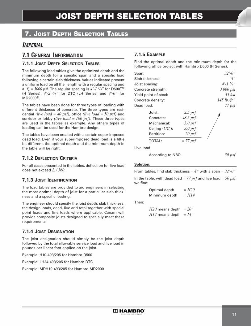
JOIST DEPTH SELECTION TABLES
11
7. JOIST DEPTH SELECTION TABLES
IMPERIAL
7.1 GENERAL INFORMATION
7.1.1 JOIST DEPTH SELECTION TABLES
The following load tables give the optimized depth and theminimum depth for a specific span and a specific loadfollowing a certain slab thickness. Values indicated presenta uniform load on all the length with a regular spacing anda f’c = 3000 psi. The regular spacing is 4’-1 1/4” for D500TM
(H Series), 4’-2 5/8” for DTC (LH Series) and 4’-0” forMD2000®.
The tables have been done for three types of loading with different thickness of concrete. The three types are resi-dential (live load = 40 psf), office (live load = 50 psf) andcorridor or lobby (live load = 100 psf). These three typesare used in the tables as example. Any others types ofloading can be used for the Hambro design.
The tables have been created with a certain super-imposeddead load. Even if your superimposed dead load is a littlebit different, the optimal depth and the minimum depth inthe table will be right.
7.1.2 DEFLECTION CRITERIA
For all cases presented in the tables, deflection for live loaddoes not exceed L / 360.
7.1.3 JOIST IDENTIFICATION
The load tables are provided to aid engineers in selectingthe most optimal depth of joist for a particular slab thick-ness and a specific loading.
The engineer should specify the joist depth, slab thickness, the design loads, dead, live and total together with special point loads and line loads where applicable. Canam will provide composite joists designed to specially meet theserequirements.
7.1.4 JOIST DESIGNATION
The joist designation should simply be the joist depthfollowed by the total allowable service load and live load inpounds per linear foot applied on the joist.
Example: H10-493/205 for Hambro D500
Example: LH24-493/205 for Hambro DTC
Example: MDH10-493/205 for Hambro MD2000
7.1.5 EXAMPLE
Find the optimal depth and the minimum depth for the following office project with Hambro D500 (H Series).
Span: 32’-0”Slab thickness: 4”Joist spacing: 4’-1 1/4”Concrete strength: 3 000 psiYield point of steel: 55 ksiConcrete density: 145 lb./ft.3
Dead load: 77 psf
Joist: 2.5 psfConcrete: 48.5 psfMechanical: 3.0 psfCeiling (1/2”): 3.0 psfPartition: 20 psf
TOTAL: = 77 psf
Live load
According to NBC: 50 psf
Solution:
From tables, find slab thickness = 4” with a span = 32’-0”
In the table, with dead load = 77 psf and live load = 50 psf,we find:
Optimal depth = H20Minimum depth = H14
Then:
H20 means depth = 20”H14 means depth = 14”
MEP-Technical Manual CDN 0408.qxd 08/04/2009 18:06 Page 45
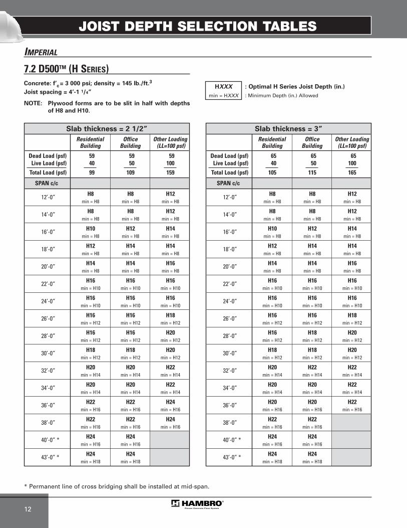
JOIST DEPTH SELECTION TABLES
12
IMPERIAL
7.2 D500TM (H SERIES)
* Permanent line of cross bridging shall be installed at mid-span.
Concrete: f’c = 3 000 psi; density = 145 lb./ft.3
Joist spacing = 4’-1 1/4”
NOTE: Plywood forms are to be slit in half with depths
of H8 and H10.
HXXX
min = HXXX
: Optimal H Series Joist Depth (in.)
: Minimum Depth (in.) Allowed
Slab thickness = 3”
Residential Office Other LoadingBuilding Building (LL=100 psf)
Dead Load (psf) 65 65 65Live Load (psf) 40 50 100
Total Load (psf) 105 115 165
SPAN c/c
12’-0” H8 H8 H12min = H8 min = H8 min = H8
14’-0” H8 H8 H12min = H8 min = H8 min = H8
16’-0” H10 H12 H14min = H8 min = H8 min = H8
18’-0” H12 H14 H14min = H8 min = H8 min = H8
20’-0” H14 H14 H16min = H8 min = H8 min = H8
22’-0” H16 H16 H16min = H10 min = H10 min = H10
24’-0” H16 H16 H16min = H10 min = H10 min = H10
26’-0” H16 H16 H18min = H12 min = H12 min = H12
28’-0” H16 H18 H20min = H12 min = H12 min = H12
30’-0” H18 H18 H20min = H12 min = H12 min = H12
32’-0” H20 H22 H22min = H14 min = H14 min = H14
34’-0” H20 H20 H22min = H14 min = H14 min = H14
36’-0” H20 H20 H22min = H16 min = H16 min = H16
38’-0” H22 H22min = H16 min = H16
40’-0” * H24 H24min = H16 min = H16
43’-0” * H24 H24min = H18 min = H18
Slab thickness = 2 1/2”
Residential Office Other LoadingBuilding Building (LL=100 psf)
Dead Load (psf) 59 59 59Live Load (psf) 40 50 100
Total Load (psf) 99 109 159
SPAN c/c
12’-0” H8 H8 H12min = H8 min = H8 min = H8
14’-0” H8 H8 H12min = H8 min = H8 min = H8
16’-0” H10 H12 H14min = H8 min = H8 min = H8
18’-0” H12 H14 H14min = H8 min = H8 min = H8
20’-0” H14 H14 H16min = H8 min = H8 min = H8
22’-0” H16 H16 H16min = H10 min = H10 min = H10
24’-0” H16 H16 H16min = H10 min = H10 min = H10
26’-0” H16 H16 H18min = H12 min = H12 min = H12
28’-0” H16 H16 H20min = H12 min = H12 min = H12
30’-0” H18 H18 H20min = H12 min = H12 min = H12
32’-0” H20 H20 H22min = H14 min = H14 min = H14
34’-0” H20 H20 H22min = H14 min = H14 min = H14
36’-0” H22 H22 H24min = H16 min = H16 min = H16
38’-0” H22 H22 H24min = H16 min = H16 min = H16
40’-0” * H24 H24min = H16 min = H16
43’-0” * H24 H24min = H18 min = H18
MEP-Technical Manual CDN 0408.qxd 08/04/2009 18:06 Page 46
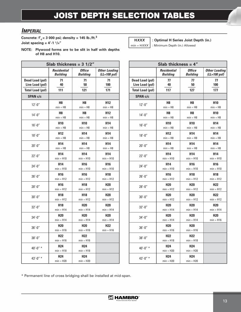
JOIST DEPTH SELECTION TABLES
13
IMPERIAL
* Permanent line of cross bridging shall be installed at mid-span.
Concrete: f’c = 3 000 psi; density = 145 lb./ft.3
Joist spacing = 4’-1 1/4”
NOTE: Plywood forms are to be slit in half with depths
of H8 and H10.
HXXX
min = HXXX
: Optimal H Series Joist Depth (in.)
: Minimum Depth (in.) Allowed
Slab thickness = 4”
Residential Office Other LoadingBuilding Building (LL=100 psf)
Dead Load (psf) 77 77 77Live Load (psf) 40 50 100
Total Load (psf) 117 127 177
SPAN c/c
12’-0” H8 H8 H10min = H8 min = H8 min = H8
14’-0” H8 H8 H10min = H8 min = H8 min = H8
16’-0” H10 H10 H14min = H8 min = H8 min = H8
18’-0” H12 H14 H14min = H8 min = H8 min = H8
20’-0” H14 H14 H14min = H8 min = H8 min = H8
22’-0” H14 H14 H14min = H10 min = H10 min = H10
24’-0” H14 H16 H16min = H10 min = H10 min = H10
26’-0” H16 H18 H18min = H12 min = H12 min = H12
28’-0” H20 H20 H22min = H12 min = H12 min = H12
30’-0” H20 H20 H22min = H12 min = H12 min = H12
32’-0” H20 H20 H20min = H14 min = H14 min = H14
34’-0” H20 H20 H20min = H14 min = H14 min = H16
36’-0” H20 H20min = H16 min = H16
38’-0” H22 H22min = H18 min = H18
40’-0” * H24 H24min = H20 min = H20
43’-0” * H24 H24min = H20 min = H20
Slab thickness = 3 1/2”
Residential Office Other LoadingBuilding Building (LL=100 psf)
Dead Load (psf) 71 71 71Live Load (psf) 40 50 100
Total Load (psf) 111 121 171
SPAN c/c
12’-0” H8 H8 H12min = H8 min = H8 min = H8
14’-0” H8 H8 H12min = H8 min = H8 min = H8
16’-0” H10 H10 H14min = H8 min = H8 min = H8
18’-0” H12 H14 H14min = H8 min = H8 min = H8
20’-0” H14 H14 H14min = H8 min = H8 min = H8
22’-0” H14 H14 H14min = H10 min = H10 min = H10
24’-0” H14 H16 H16min = H10 min = H10 min = H10
26’-0” H16 H16 H18min = H12 min = H12 min = H12
28’-0” H16 H18 H20min = H12 min = H12 min = H12
30’-0” H18 H18 H20min = H12 min = H12 min = H12
32’-0” H18 H20 H20min = H14 min = H14 min = H14
34’-0” H20 H20 H20min = H14 min = H14 min = H14
36’-0” H20 H20 H22min = H16 min = H16 min = H16
38’-0” H22 H22min = H16 min = H16
40’-0” * H24 H24min = H18 min = H18
43’-0” * H24 H24min = H20 min = H20
MEP-Technical Manual CDN 0408.qxd 08/04/2009 18:06 Page 47
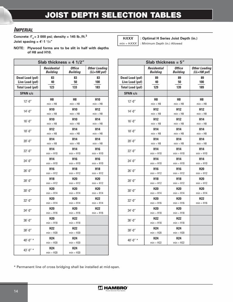
JOIST DEPTH SELECTION TABLES
14
IMPERIAL
* Permanent line of cross bridging shall be installed at mid-span.
Concrete: f’c = 3 000 psi; density = 145 lb./ft.3
Joist spacing = 4’-1 1/4”
NOTE: Plywood forms are to be slit in half with depths
of H8 and H10.
HXXX
min = HXXX
: Optimal H Series Joist Depth (in.)
: Minimum Depth (in.) Allowed
Slab thickness = 5”
Residential Office Other LoadingBuilding Building (LL=100 psf)
Dead Load (psf) 89 89 89Live Load (psf) 40 50 100
Total Load (psf) 129 139 189
SPAN c/c
12’-0” H8 H8 H8min = H8 min = H8 min = H8
14’-0” H12 H12 H12min = H8 min = H8 min = H8
16’-0” H12 H12 H14min = H8 min = H8 min = H8
18’-0” H14 H14 H14min = H8 min = H8 min = H8
20’-0” H14 H14 H14min = H8 min = H8 min = H8
22’-0” H14 H14 H14min = H10 min = H10 min = H10
24’-0” H14 H14 H14min = H10 min = H10 min = H10
26’-0” H16 H16 H20min = H12 min = H12 min = H12
28’-0” H18 H18 H20min = H12 min = H12 min = H12
30’-0” H20 H20 H20min = H14 min = H14 min = H14
32’-0” H20 H20 H22min = H16 min = H16 min = H16
34’-0” H20 H20min = H18 min = H18
36’-0” H22 H22min = H18 min = H18
38’-0” H24 H24min = H20 min = H20
40’-0” * H24 H24min = H22 min = H22
Slab thickness = 4 1/2”
Residential Office Other LoadingBuilding Building (LL=100 psf)
Dead Load (psf) 83 83 83Live Load (psf) 40 50 100
Total Load (psf) 123 133 183
SPAN c/c
12’-0” H8 H8 H10min = H8 min = H8 min = H8
14’-0” H10 H10 H12min = H8 min = H8 min = H8
16’-0” H10 H10 H14min = H8 min = H8 min = H8
18’-0” H12 H14 H14min = H8 min = H8 min = H8
20’-0” H14 H14 H14min = H8 min = H8 min = H8
22’-0” H14 H14 H16min = H10 min = H10 min = H10
24’-0” H14 H16 H16min = H10 min = H10 min = H10
26’-0” H16 H18 H18min = H12 min = H12 min = H12
28’-0” H18 H20 H20min = H12 min = H12 min = H12
30’-0” H20 H20 H20min = H14 min = H14 min = H14
32’-0” H20 H20 H22min = H14 min = H14 min = H14
34’-0” H20 H20 H22min = H16 min = H16 min = H16
36’-0” H20 H22min = H18 min = H18
38’-0” H22 H22min = H20 min = H20
40’-0” * H24 H24min = H20 min = H20
43’-0” * H24 H24min = H20 min = H20
MEP-Technical Manual CDN 0408.qxd 08/04/2009 18:06 Page 48

JOIST DEPTH SELECTION TABLES
15
IMPERIAL
7.3 MD2000® SERIES
* Permanent line of cross bridging shall be installed at mid-span.
Concrete: f’c = 3 000 psi; density = 145 lb./ft.3
Joist spacing = 4’-0” MDHXXX
min = MDHXXX
: Optimal MD2000 Series Joist Depth (in.)
: Minimum Depth (in.) Allowed
Slab thickness = 4 1/2”
Residential Office Other LoadingBuilding Building (LL=100 psf)
Dead Load (psf) 73 73 73Live Load (psf) 40 50 100
Total Load (psf) 113 123 173
SPAN c/c
12’-0” MDH8 MDH8 MDH12min = MDH8 min = MDH8 min = MDH8
14’-0” MDH8 MDH12 MDH12min = MDH8 min = MDH8 min = MDH8
16’-0” MDH10 MDH12 MDH14min = MDH8 min = MDH8 min = MDH8
18’-0” MDH12 MDH14 MDH16min = MDH8 min = MDH8 min = MDH8
20’-0” MDH14 MDH14 MDH14min = MDH8 min = MDH8 min = MDH8
22’-0” MDH14 MDH16 MDH16min = MDH10 min = MDH10 min = MDH10
24’-0” MDH16 MDH16 MDH16min = MDH10 min = MDH10 min = MDH10
26’-0” MDH16 MDH16 MDH18min = MDH12 min = MDH12 min = MDH12
28’-0” MDH16 MDH16 MDH20min = MDH12 min = MDH12 min = MDH12
30’-0” MDH18 MDH18 MDH20min = MDH12 min = MDH12 min = MDH12
32’-0” MDH18 MDH20 MDH20min = MDH14 min = MDH14 min = MDH14
34’-0” MDH20 MDH20 MDH20min = MDH14 min = MDH14 min = MDH14
36’-0” MDH20 MDH22 MDH22min = MDH16 min = MDH16 min = MDH16
38’-0” MDH22 MDH22 MDH22min = MDH16 min = MDH16 min = MDH16
40’-0” * MDH22 MDH22 MDH22min = MDH16 min = MDH16 min = MDH16
43’-0” * MDH22 MDH24 MDH24min = MDH18 min = MDH18 min = MDH18
Slab thickness = 4 1/4”
Residential Office Other LoadingBuilding Building (LL=100 psf)
Dead Load (psf) 70 70 70Live Load (psf) 40 50 100
Total Load (psf) 110 120 170
SPAN c/c
12’-0” MDH8 MDH8 MDH12min = MDH8 min = MDH8 min = MDH8
14’-0” MDH8 MDH12 MDH12min = MDH8 min = MDH8 min = MDH8
16’-0” MDH10 MDH12 MDH14min = MDH8 min = MDH8 min = MDH8
18’-0” MDH12 MDH14 MDH14min = MDH8 min = MDH8 min = MDH8
20’-0” MDH14 MDH14 MDH14min = MDH8 min = MDH8 min = MDH8
22’-0” MDH14 MDH16 MDH16min = MDH10 min = MDH10 min = MDH10
24’-0” MDH16 MDH16 MDH16min = MDH10 min = MDH10 min = MDH10
26’-0” MDH16 MDH16 MDH18min = MDH12 min = MDH12 min = MDH12
28’-0” MDH16 MDH16 MDH20min = MDH12 min = MDH12 min = MDH12
30’-0” MDH18 MDH18 MDH20min = MDH12 min = MDH12 min = MDH12
32’-0” MDH18 MDH18 MDH20min = MDH14 min = MDH14 min = MDH14
34’-0” MDH20 MDH20 MDH20min = MDH14 min = MDH14 min = MDH14
36’-0” MDH20 MDH22 MDH22min = MDH16 min = MDH16 min = MDH16
38’-0” MDH22 MDH22 MDH22min = MDH16 min = MDH16 min = MDH16
40’-0” * MDH22 MDH22 MDH22min = MDH16 min = MDH16 min = MDH16
43’-0” * MDH22 MDH22 MDH24min = MDH18 min = MDH18 min = MDH18
MEP-Technical Manual CDN 0408.qxd 08/04/2009 18:06 Page 49
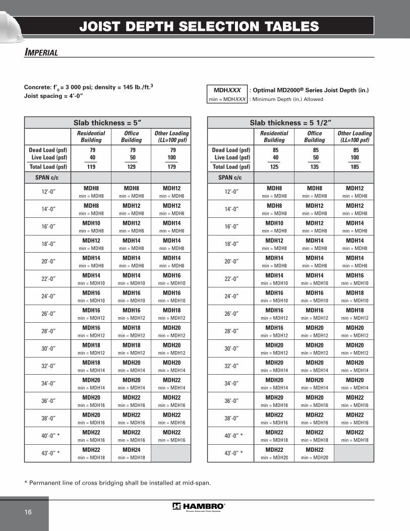
JOIST DEPTH SELECTION TABLES
16
IMPERIAL
* Permanent line of cross bridging shall be installed at mid-span.
Concrete: f’c = 3 000 psi; density = 145 lb./ft.3
Joist spacing = 4’-0” MDHXXX
min = MDHXXX
: Optimal MD2000® Series Joist Depth (in.)
: Minimum Depth (in.) Allowed
Slab thickness = 5 1/2”
Residential Office Other LoadingBuilding Building (LL=100 psf)
Dead Load (psf) 85 85 85Live Load (psf) 40 50 100
Total Load (psf) 125 135 185
SPAN c/c
12’-0” MDH8 MDH8 MDH12min = MDH8 min = MDH8 min = MDH8
14’-0” MDH8 MDH12 MDH12min = MDH8 min = MDH8 min = MDH8
16’-0” MDH10 MDH12 MDH14min = MDH8 min = MDH8 min = MDH8
18’-0” MDH12 MDH14 MDH14min = MDH8 min = MDH8 min = MDH8
20’-0” MDH14 MDH14 MDH14min = MDH8 min = MDH8 min = MDH8
22’-0” MDH14 MDH14 MDH16min = MDH10 min = MDH10 min = MDH10
24’-0” MDH16 MDH16 MDH18min = MDH10 min = MDH10 min = MDH10
26’-0” MDH16 MDH16 MDH18min = MDH12 min = MDH12 min = MDH12
28’-0” MDH16 MDH20 MDH20min = MDH12 min = MDH12 min = MDH12
30’-0” MDH20 MDH20 MDH20min = MDH12 min = MDH12 min = MDH12
32’-0” MDH20 MDH20 MDH20min = MDH14 min = MDH14 min = MDH14
34’-0” MDH20 MDH20 MDH20min = MDH14 min = MDH14 min = MDH14
36’-0” MDH20 MDH20 MDH22min = MDH16 min = MDH16 min = MDH16
38’-0” MDH22 MDH22 MDH22min = MDH16 min = MDH16 min = MDH16
40’-0” * MDH22 MDH22 MDH22min = MDH18 min = MDH18 min = MDH18
43’-0” * MDH22 MDH22min = MDH20 min = MDH20
Slab thickness = 5”
Residential Office Other LoadingBuilding Building (LL=100 psf)
Dead Load (psf) 79 79 79Live Load (psf) 40 50 100
Total Load (psf) 119 129 179
SPAN c/c
12’-0” MDH8 MDH8 MDH12min = MDH8 min = MDH8 min = MDH8
14’-0” MDH8 MDH12 MDH12min = MDH8 min = MDH8 min = MDH8
16’-0” MDH10 MDH12 MDH14min = MDH8 min = MDH8 min = MDH8
18’-0” MDH12 MDH14 MDH14min = MDH8 min = MDH8 min = MDH8
20’-0” MDH14 MDH14 MDH14min = MDH8 min = MDH8 min = MDH8
22’-0” MDH14 MDH14 MDH16min = MDH10 min = MDH10 min = MDH10
24’-0” MDH16 MDH16 MDH16min = MDH10 min = MDH10 min = MDH10
26’-0” MDH16 MDH16 MDH18min = MDH12 min = MDH12 min = MDH12
28’-0” MDH16 MDH18 MDH20min = MDH12 min = MDH12 min = MDH12
30’-0” MDH18 MDH18 MDH20min = MDH12 min = MDH12 min = MDH12
32’-0” MDH18 MDH20 MDH20min = MDH14 min = MDH14 min = MDH14
34’-0” MDH20 MDH20 MDH22min = MDH14 min = MDH14 min = MDH14
36’-0” MDH20 MDH22 MDH22min = MDH16 min = MDH16 min = MDH16
38’-0” MDH20 MDH22 MDH22min = MDH16 min = MDH16 min = MDH16
40’-0” * MDH22 MDH22 MDH22min = MDH16 min = MDH16 min = MDH16
43’-0” * MDH22 MDH24min = MDH18 min = MDH18
MEP-Technical Manual CDN 0408.qxd 08/04/2009 18:06 Page 50
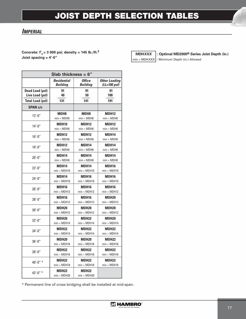
JOIST DEPTH SELECTION TABLES
17
IMPERIAL
* Permanent line of cross bridging shall be installed at mid-span.
Concrete: f’c = 3 000 psi; density = 145 lb./ft.3
Joist spacing = 4’-0” MDHXXX
min = MDHXXX
: Optimal MD2000® Series Joist Depth (in.)
: Minimum Depth (in.) Allowed
Slab thickness = 6”
Residential Office Other LoadingBuilding Building (LL=100 psf)
Dead Load (psf) 91 91 91Live Load (psf) 40 50 100
Total Load (psf) 131 141 191
SPAN c/c
12’-0” MDH8 MDH8 MDH12min = MDH8 min = MDH8 min = MDH8
14’-0” MDH10 MDH12 MDH12min = MDH8 min = MDH8 min = MDH8
16’-0” MDH12 MDH12 MDH14min = MDH8 min = MDH8 min = MDH8
18’-0” MDH12 MDH14 MDH14min = MDH8 min = MDH8 min = MDH8
20’-0” MDH14 MDH14 MDH14min = MDH8 min = MDH8 min = MDH8
22’-0” MDH14 MDH14 MDH16min = MDH10 min = MDH10 min = MDH10
24’-0” MDH14 MDH16 MDH16min = MDH10 min = MDH10 min = MDH10
26’-0” MDH16 MDH16 MDH16min = MDH12 min = MDH12 min = MDH12
28’-0” MDH16 MDH16 MDH20min = MDH12 min = MDH12 min = MDH12
30’-0” MDH20 MDH20 MDH20min = MDH12 min = MDH12 min = MDH12
32’-0” MDH20 MDH22 MDH20min = MDH14 min = MDH14 min = MDH14
34’-0” MDH22 MDH22 MDH22min = MDH14 min = MDH14 min = MDH14
36’-0” MDH20 MDH20 MDH22min = MDH16 min = MDH16 min = MDH16
38’-0” MDH22 MDH22 MDH22min = MDH16 min = MDH16 min = MDH16
40’-0” * MDH22 MDH22 MDH22min = MDH18 min = MDH18 min = MDH18
43’-0” * MDH22 MDH22min = MDH20 min = MDH20
MEP-Technical Manual CDN 0408.qxd 08/04/2009 18:06 Page 51

JOIST DEPTH SELECTION TABLES
18
IMPERIAL
7.4 DTC (LH SERIES)
* Permanent line of cross bridging shall be installed at mid-span.
Concrete: f’c = 3 000 psi; density = 145 lb./ft.3
Joist spacing = 4’-2 5/8”
NOTE: Plywood forms have to be slit in half for
any depth.
LHXXX
min = LHXXX
: Optimal LH Series Joist Depth (in.)
: Minimum Depth (in.) Allowed
Slab thickness = 3 1/2”
Residential Office Other LoadingBuilding Building (LL=100 psf)
Dead Load (psf) 72 72 72Live Load (psf) 40 50 100
Total Load (psf) 112 122 172
SPAN c/c
30’-0” LH20 LH20 LH24min = LH16 min = LH16 min = LH20
32’-0” LH20 LH24 LH28min = LH16 min = LH16 min = LH20
34’-0” LH24 LH24 LH28min = LH16 min = LH16 min = LH24
36’-0” LH28 LH28 LH32min = LH16 min = LH16 min = LH24
38’-0” LH28 LH28 LH32min = LH20 min = LH20 min = LH28
40’-0” * LH32 LH32 LH36min = LH20 min = LH20 min = LH28
42’-0” * LH28 LH32 LH32min = LH20 min = LH20 min = LH32
44’-0” * LH32 LH36 LH36min = LH24 min = LH24 min = LH32
46’-0” * LH36 LH36 LH36min = LH24 min = LH24 min = LH36
48’-0” * LH36 LH32 LH36min = LH24 min = LH24 min = LH36
50’-0” * LH36 LH36min = LH24 min = LH24
52’-0” * LH36 LH36min = LH24 min = LH24
Slab thickness = 3”
Residential Office Other LoadingBuilding Building (LL=100 psf)
Dead Load (psf) 66 66 66Live Load (psf) 40 50 100
Total Load (psf) 106 116 166
SPAN c/c
30’-0” LH20 LH20 LH24min = LH16 min = LH16 min = LH20
32’-0” LH20 LH24 LH32min = LH16 min = LH16 min = LH20
34’-0” LH24 LH24 LH28min = LH16 min = LH16 min = LH24
36’-0” LH24 LH24 LH28min = LH20 min = LH20 min = LH24
38’-0” LH28 LH32 LH32min = LH20 min = LH20 min = LH28
40’-0” * LH32 LH32 LH36min = LH20 min = LH20 min = LH28
42’-0” * LH28 LH32 LH36min = LH20 min = LH20 min = LH32
44’-0” * LH32 LH36 LH36min = LH24 min = LH24 min = LH32
46’-0” * LH32 LH32 LH36min = LH24 min = LH24 min = LH36
48’-0” * LH32 LH36 LH36min = LH24 min = LH24 min = LH36
50’-0” * LH36 LH36min = LH24 min = LH24
52’-0” * LH36 LH36min = LH24 min = LH24
MEP-Technical Manual CDN 0408.qxd 08/04/2009 18:06 Page 52

JOIST DEPTH SELECTION TABLES
19
IMPERIAL
* Permanent line of cross bridging shall be installed at mid-span.
Concrete: f’c = 3 000 psi; density = 145 lb./ft.3
Joist spacing = 4’-2 5/8”
NOTE: Plywood forms have to be slit in half for
any depth.
LHXXX
min = LHXXX
: Optimal LH Series Joist Depth (in.)
: Minimum Depth (in.) Allowed
Slab thickness = 4 1/2”
Residential Office Other LoadingBuilding Building (LL=100 psf)
Dead Load (psf) 84 84 84Live Load (psf) 40 50 100
Total Load (psf) 124 134 184
SPAN c/c
30’-0” LH20 LH20 LH24min = LH16 min = LH16 min = LH20
32’-0” LH24 LH24 LH28min = LH16 min = LH16 min = LH20
34’-0” LH24 LH28 LH32min = LH16 min = LH16 min = LH24
36’-0” LH32 LH32 LH32min = LH20 min = LH20 min = LH24
38’-0” LH32 LH32 LH32min = LH20 min = LH20 min = LH24
40’-0” * LH32 LH32 LH32min = LH24 min = LH24 min = LH28
42’-0” * LH32 LH32 LH32min = LH24 min = LH24 min = LH32
44’-0” * LH36 LH36 LH36min = LH24 min = LH24 min = LH32
46’-0” * LH36 LH32 LH36min = LH24 min = LH24 min = LH36
48’-0” * LH36 LH36 LH36min = LH24 min = LH24 min = LH36
50’-0” * LH36 LH36min = LH28 min = LH28
52’-0” * LH36min = LH28
Slab thickness = 4”
Residential Office Other LoadingBuilding Building (LL=100 psf)
Dead Load (psf) 79 79 79Live Load (psf) 40 50 100
Total Load (psf) 119 129 179
SPAN c/c
30’-0” LH20 LH20 LH24min = LH16 min = LH16 min = LH20
32’-0” LH20 LH24 LH28min = LH16 min = LH16 min = LH20
34’-0” LH24 LH28 LH32min = LH16 min = LH16 min = LH24
36’-0” LH28 LH32 LH32min = LH16 min = LH16 min = LH24
38’-0” LH32 LH32 LH32min = LH20 min = LH20 min = LH28
40’-0” * LH28 LH32 LH32min = LH20 min = LH20 min = LH28
42’-0” * LH32 LH32 LH32min = LH20 min = LH20 min = LH32
44’-0” * LH32 LH32 LH36min = LH24 min = LH24 min = LH32
46’-0” * LH32 LH36 LH36min = LH24 min = LH24 min = LH36
48’-0” * LH36 LH36 LH36min = LH24 min = LH24 min = LH36
50’-0” * LH36 LH36min = LH24 min = LH24
52’-0” * LH36 LH36min = LH28 min = LH28
MEP-Technical Manual CDN 0408.qxd 08/04/2009 18:06 Page 53
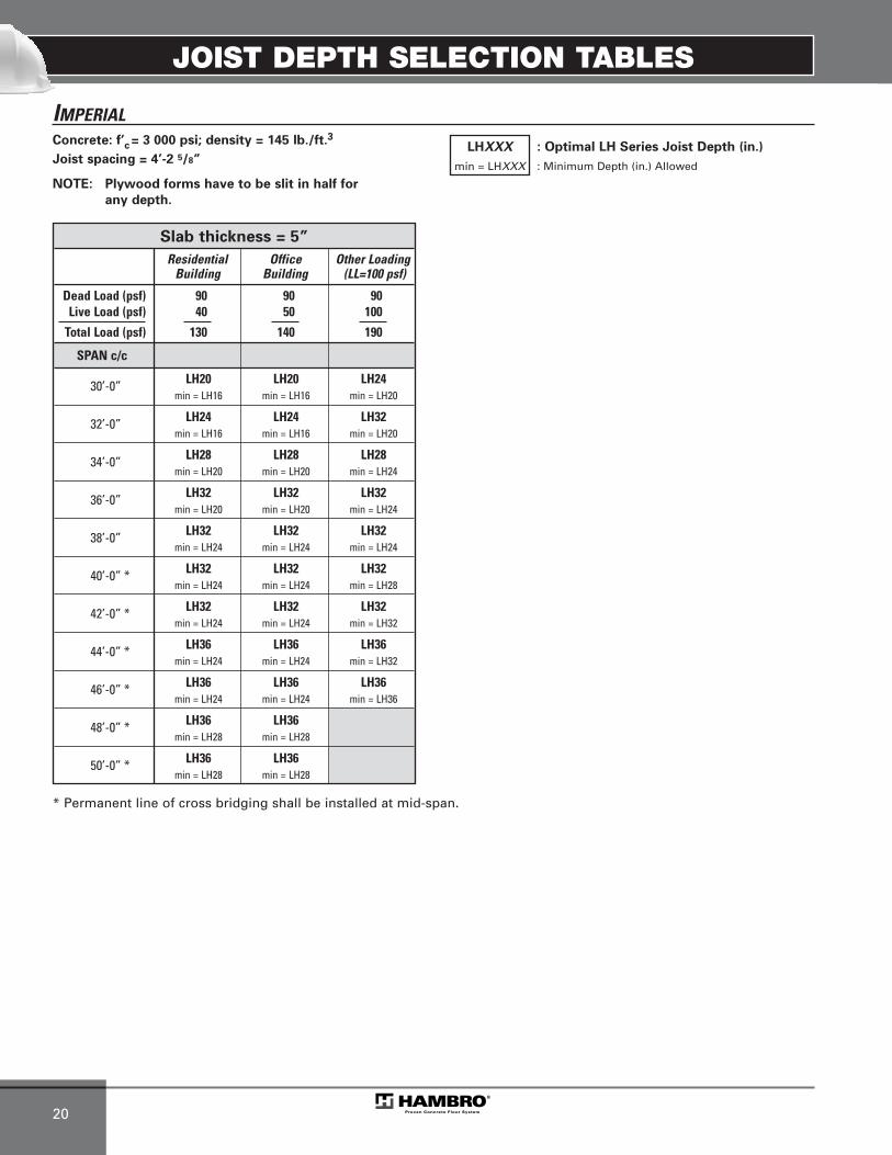
JOIST DEPTH SELECTION TABLES
20
IMPERIAL
* Permanent line of cross bridging shall be installed at mid-span.
Concrete: f’c = 3 000 psi; density = 145 lb./ft.3
Joist spacing = 4’-2 5/8”
NOTE: Plywood forms have to be slit in half for
any depth.
LHXXX
min = LHXXX
: Optimal LH Series Joist Depth (in.)
: Minimum Depth (in.) Allowed
Slab thickness = 5”
Residential Office Other LoadingBuilding Building (LL=100 psf)
Dead Load (psf) 90 90 90Live Load (psf) 40 50 100
Total Load (psf) 130 140 190
SPAN c/c
30’-0” LH20 LH20 LH24min = LH16 min = LH16 min = LH20
32’-0” LH24 LH24 LH32min = LH16 min = LH16 min = LH20
34’-0” LH28 LH28 LH28min = LH20 min = LH20 min = LH24
36’-0” LH32 LH32 LH32min = LH20 min = LH20 min = LH24
38’-0” LH32 LH32 LH32min = LH24 min = LH24 min = LH24
40’-0” * LH32 LH32 LH32min = LH24 min = LH24 min = LH28
42’-0” * LH32 LH32 LH32min = LH24 min = LH24 min = LH32
44’-0” * LH36 LH36 LH36min = LH24 min = LH24 min = LH32
46’-0” * LH36 LH36 LH36min = LH24 min = LH24 min = LH36
48’-0” * LH36 LH36min = LH28 min = LH28
50’-0” * LH36 LH36min = LH28 min = LH28
MEP-Technical Manual CDN 0408.qxd 08/04/2009 18:06 Page 54
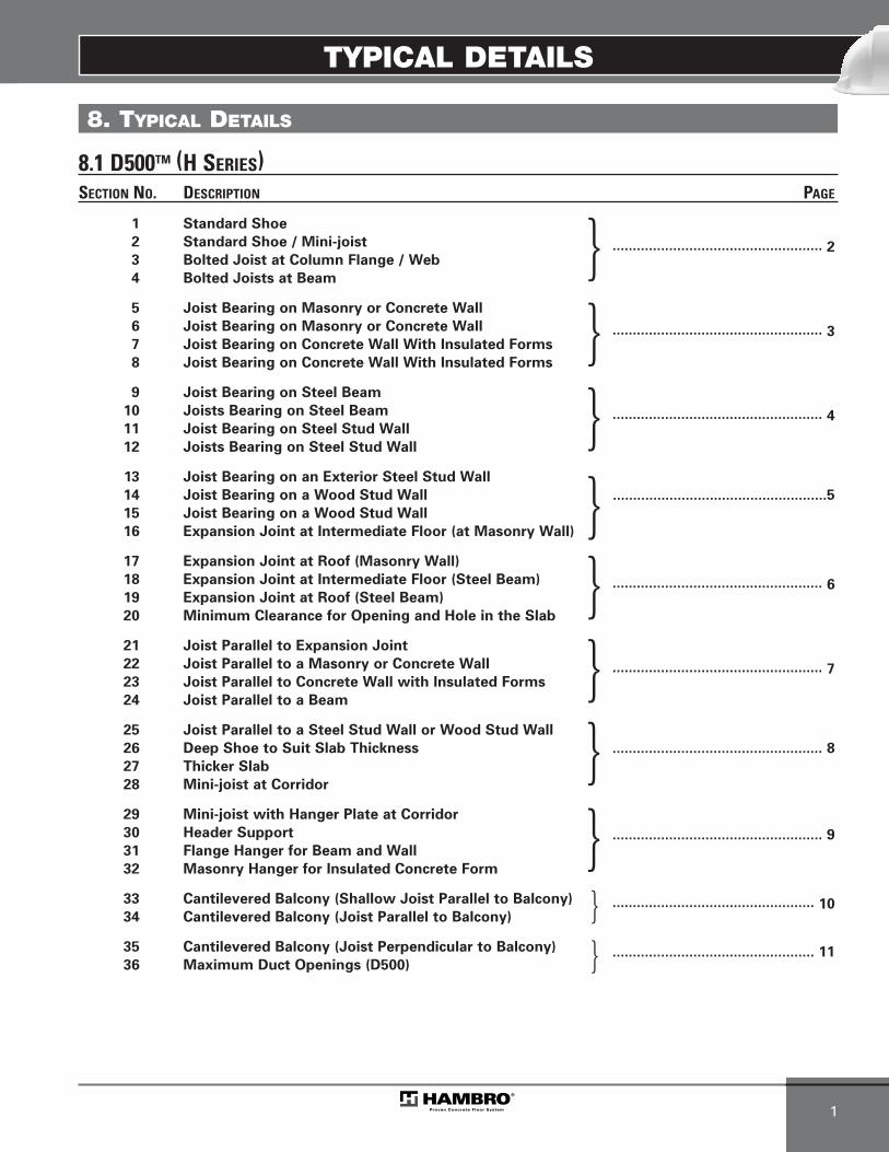
TYPICAL DETAILS
1
8. TYPICAL DETAILS
SECTION NO. DESCRIPTION PAGE
1 Standard Shoe
2 Standard Shoe / Mini-joist
3 Bolted Joist at Column Flange / Web .................................................... 2
4 Bolted Joists at Beam
5 Joist Bearing on Masonry or Concrete Wall
6 Joist Bearing on Masonry or Concrete Wall
7 Joist Bearing on Concrete Wall With Insulated Forms .................................................... 3
8 Joist Bearing on Concrete Wall With Insulated Forms
9 Joist Bearing on Steel Beam
10 Joists Bearing on Steel Beam
11 Joist Bearing on Steel Stud Wall.................................................... 4
12 Joists Bearing on Steel Stud Wall
13 Joist Bearing on an Exterior Steel Stud Wall
14 Joist Bearing on a Wood Stud Wall .....................................................5
15 Joist Bearing on a Wood Stud Wall
16 Expansion Joint at Intermediate Floor (at Masonry Wall)
17 Expansion Joint at Roof (Masonry Wall)
18 Expansion Joint at Intermediate Floor (Steel Beam)
19 Expansion Joint at Roof (Steel Beam).................................................... 6
20 Minimum Clearance for Opening and Hole in the Slab
21 Joist Parallel to Expansion Joint
22 Joist Parallel to a Masonry or Concrete Wall
23 Joist Parallel to Concrete Wall with Insulated Forms.................................................... 7
24 Joist Parallel to a Beam
25 Joist Parallel to a Steel Stud Wall or Wood Stud Wall
26 Deep Shoe to Suit Slab Thickness .................................................... 8
27 Thicker Slab
28 Mini-joist at Corridor
29 Mini-joist with Hanger Plate at Corridor
30 Header Support
31 Flange Hanger for Beam and Wall .................................................... 9
32 Masonry Hanger for Insulated Concrete Form
33 Cantilevered Balcony (Shallow Joist Parallel to Balcony)
34 Cantilevered Balcony (Joist Parallel to Balcony) .................................................. 10
35 Cantilevered Balcony (Joist Perpendicular to Balcony)
36 Maximum Duct Openings (D500) .................................................. 11
}}}}}}}}}
}
8.1 D500TM (H SERIES)
MEP-Technical Manual CDN 0408.qxd 08/04/2009 18:06 Page 55

TYPICAL DETAILS
2
TOP
CHOR
D
TOP
OF S
LAB
FIRS
T DI
AGON
AL
SLAB(T)
100
mm
(4î)
45 mm (1 3/4”)
6 mm (1/4”)
WEL
DED
WIR
E-M
ESH
T +
6 m
m (1
/4”)
= S
LAB
TH
ICKN
ESS
+ SH
OE
THIC
KNES
S
SOLI
D M
ASON
RY W
ALL,
ACCO
RDIN
G TO
THE
SPE
CIFI
CATI
ONS
OF T
HE C
ONSU
LTIN
G EN
GIN
EER
(FIL
L TH
E M
ASON
RY B
LOCK
WIT
H M
ORTA
R,UN
DER
THE
JOIS
T SH
OE)
REBA
R(IF
REQ
UIRE
D BY
THE
CON
SULT
ING
ENGI
NEE
R)
90 m
m (3
1 /2”)
MIN
. FOR
100 m
m (4”
) SHO
E (TY
P.)
CEIL
ING
EXTE
NSI
ON
T + 6 mm (1/4”)
(D)
NOMINALJOIST DEPTH
TOP OF BEARING
MIN
I JOI
ST
SLAB(T)
SECT
ION
1 - S
TAN
DA
RDSH
OE
SECT
ION
2 - S
TAN
DA
RDSH
OE
/MIN
I-JO
IST
WEL
DED
WIR
E-M
ESH
(D)(T)
CEIL
ING
EXTE
NSI
ON
- T+
6 m
m (1
/4”)
= S
LAB
TH
ICKN
ESS
+ SH
OE
THIC
KNES
S- S
HO
E W
IDTH
= 1
90 m
m (7
1 /2”
)
STEE
L CO
LUM
N, A
CCOR
DIN
G TO
THE
SPE
CIFI
CATI
ONS
OF T
HE C
ONSU
LTIN
G EN
GIN
EER
(U.N
.O)
21 x
32
mm
(13 /1
6” x
1 1 /
4”) S
LOTS
@ 1
25 m
m (5
”) C
/C (H
AMBR
O SH
OE)
21 m
m (1
3 /16”
) Ø H
OLES
@ 1
25 m
m (5
”) C
/C (S
UPPO
RT)
NOMINALJOIST DEPTHSLAB
65 m
m (2
1 /2”
)
100
mm
90 m
m (3
1 /2”
) MIN
. FOR
100
mm
(4”)
SHO
E (T
YP.)
TOP OF BEARINGT+ 6 mm (1/4”)
(4”)
SECT
ION
3 - B
OLT
EDJO
IST
ATCO
LUM
N(F
LAN
GE
/ WEB
)
WEL
DED
WIR
E-M
ESH
(D)(T)
CEIL
ING
EXTE
NSI
ON
T +
6 m
m (1
/4”)
= S
LAB
TH
ICKN
ESS
+ SH
OE
THIC
KNES
S
STEE
L BE
AM, A
CCOR
DIN
G TO
THE
SPE
CIFI
CATI
ONS
OF T
HE C
ONSU
LTIN
G EN
GIN
EER
(U.N
.O)
NOMINALJOIST DEPTHSLAB
21 x
32
mm
(13 /1
6” x
1 1 /
4”) S
LOTS
@
125
mm
(5”)
C/C
(HAM
BRO
SHOE
)21
mm
(13 /1
6”) Ø
HOL
ES
@ 1
25 m
m (5
”) C
/C (S
UPPO
RT)
230 m
m (9”
) FLA
NGE O
F 305
mm
(12”)
AND M
ORE
203 m
m (8”
) FLA
NGE B
ETW
EEN
254 m
m (10
”) TO
303 m
m (11
7 /8”)
152 m
m (6”
) FLA
NGE B
ETW
EEN
230 m
m (9”
) TO 2
52 m
m (9
7 /8”)
127 m
m (5”
) FLA
NGE B
ETW
EEN
190 m
m (7
1 /2”) T
O 228
mm
(8 7 /8”
)10
2 mm
(4”) F
LANG
E BET
WEE
N 15
2 mm
(6”) T
O 188
mm
(7 3 /8”
)70
mm
(2 3 /4”
) FLA
NGE B
ETW
EEN
127 m
m (5”
) TO 1
50 m
m (5
7 /8”)
58 m
m (2
1 /4”) F
LANG
E BET
WEE
N 10
0 mm
(4”) T
O 125
mm
(4 7 /8”
)
T+ 6 mm (1/4”)
TOP OF BEARING
CEIL
ING
EXTE
NSI
ON
SECT
ION
4 - B
OLT
EDJO
ISTS
ATB
EAM
MEP-Technical Manual CDN 0408.qxd 08/04/2009 18:06 Page 56
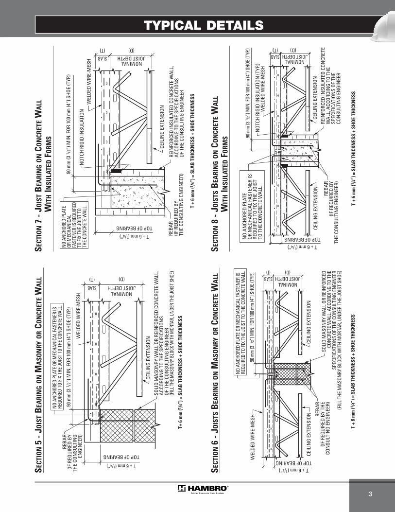
TYPICAL DETAILS
3
WEL
DED
WIR
E-M
ESH
JOIST DEPTH
(D)(T)
CEIL
ING
EXTE
NSI
ON
SOLI
D M
ASON
RY W
ALL
OR R
EIN
FORC
ED C
ONCR
ETE
WAL
L,AC
CORD
ING
TO T
HE S
PECI
FICA
TION
SOF
THE
CON
SULT
ING
ENGI
NEE
R(FI
LL TH
E MAS
ONRY
BLO
CK W
ITH
MOR
TAR,
UND
ER TH
E JOI
ST S
HOE)
T+ 6
mm
(1/4
”) =
SLA
B T
HIC
KNES
S +
SHO
E TH
ICKN
ESS
T + 6 mm (1/4”)
TOP OF BEARING
90 m
m (3
1 /2”
) MIN
. FOR
100
mm
(4”)
SHO
E (T
YP.)
NOMINALSLAB
REBA
R(IF
REQ
UIRE
D BY
THE
CON
SULT
ING
ENGI
NEE
R)
NO A
NCHO
RED
PLAT
E OR
MEC
HANI
CAL F
ASTE
NER
IS
REQU
IRED
TO
FIX
THE
JOIS
T TO
THE
CON
CRET
E W
ALL.
WEL
DED
WIR
E-M
ESH
T +
6 m
m (1
/4”)
= S
LAB
TH
ICKN
ESS
+ SH
OE
THIC
KNES
S
SOLI
D M
ASON
RY W
ALL
OR R
EIN
FORC
EDCO
NCR
ETE
WAL
L, A
CCOR
DIN
G TO
THE
SPEC
IFIC
ATIO
NS
OF T
HE C
ONSU
LTIN
G EN
GIN
EER
(FIL
L TH
E M
ASON
RY B
LOCK
WIT
H M
ORTA
R, U
NDE
R TH
E JO
IST
SHOE
)
REBA
R(IF
REQ
UIRE
D BY
THE
CON
SULT
ING
ENGI
NEE
R)
90 m
m (3
1 /2”)
MIN
. FOR
100 m
m (4
”) S
HOE
(TYP
.)
CEIL
ING
EXTE
NSI
ON
T + 6 mm (1/4”)
(D)
NOMINALJOIST DEPTH
(T)SLAB
TOP OF BEARING
CEIL
ING
EXTE
NSI
ON
NO A
NCHO
RED
PLAT
E OR
MEC
HANI
CAL F
ASTE
NER
IS
REQU
IRED
TO
FIX
THE
JOIS
T TO
THE
CON
CRET
E W
ALL.
SECT
ION
5 - J
OIS
TB
EARI
NG
ON
MA
SON
RYO
RCO
NCR
ETE
WA
LL
SECT
ION
6 - J
OIS
TSB
EARI
NG
ON
MA
SON
RYO
RCO
NCR
ETE
WA
LL
REIN
FORC
ED IN
SULA
TED
CON
CRET
E W
ALL,
ACCO
RDIN
G TO
THE
SPE
CIFI
CATI
ONS
OF T
HE C
ONSU
LTIN
G EN
GIN
EER
CEIL
ING
EXTE
NSI
ON
REBA
R(IF
REQ
UIRE
D BY
THE
CON
SULT
ING
ENGI
NEE
R)
T +
6 m
m (1
/4”)
= S
LAB
TH
ICKN
ESS
+ SH
OE
THIC
KNES
S
(D)
NOMINALJOIST DEPTH
WEL
DED
WIR
E-M
ESH
90 m
m (3
1 /2”
) MIN
. FOR
100
mm
(4”)
SHO
E (T
YP.)
TOP OF BEARING
T + 6 mm (1/4”)
(T)SLAB
NO A
NCHO
RED
PLAT
EOR
MEC
HANI
CAL
FAST
ENER
IS R
EQUI
RED
TO FI
X TH
E JO
IST
TO
THE
CONC
RETE
WAL
L.N
OTCH
RIG
ID IN
SULA
TION
REIN
FORC
ED IN
SULA
TED
CON
CRET
EW
ALL,
ACC
ORDI
NG
TO T
HE
SPEC
IFIC
ATIO
NS
OF T
HE
CON
SULT
ING
ENGI
NEE
R
CEIL
ING
EXTE
NSI
ON
REBA
R(IF
REQ
UIRE
D BY
THE
CON
SULT
ING
ENGI
NEE
R)
CEIL
ING
EXTE
NSI
ON
T +
6 m
m (1
/4”)
= S
LAB
TH
ICKN
ESS
+ SH
OE
THIC
KNES
S
(D)
NOMINALJOIST DEPTH
WEL
DED
WIR
E-M
ESH
90 m
m (3
1 /2”)
MIN
. FOR
100 m
m (4
”) S
HOE
(TYP
.)
TOP OF BEARINGT + 6 mm (1/4”)
(T)SLAB
NO
ANCH
ORED
PLA
TE
OR M
ECHA
NIC
AL F
ASTE
NER
IS
REQU
IRED
TO
FIX
THE
JOIS
TTO
THE
CON
CRET
E W
ALL.
NOT
CH R
IGID
INSU
LATI
ON (T
YP.)
SECT
ION
7 - J
OIS
TB
EARI
NG
ON
CON
CRET
EW
ALL
WIT
HIN
SULA
TED
FORM
S
SECT
ION
8 - J
OIS
TSB
EARI
NG
ON
CON
CRET
EW
ALL
WIT
HIN
SULA
TED
FORM
S
MEP-Technical Manual CDN 0408.qxd 08/04/2009 18:06 Page 57
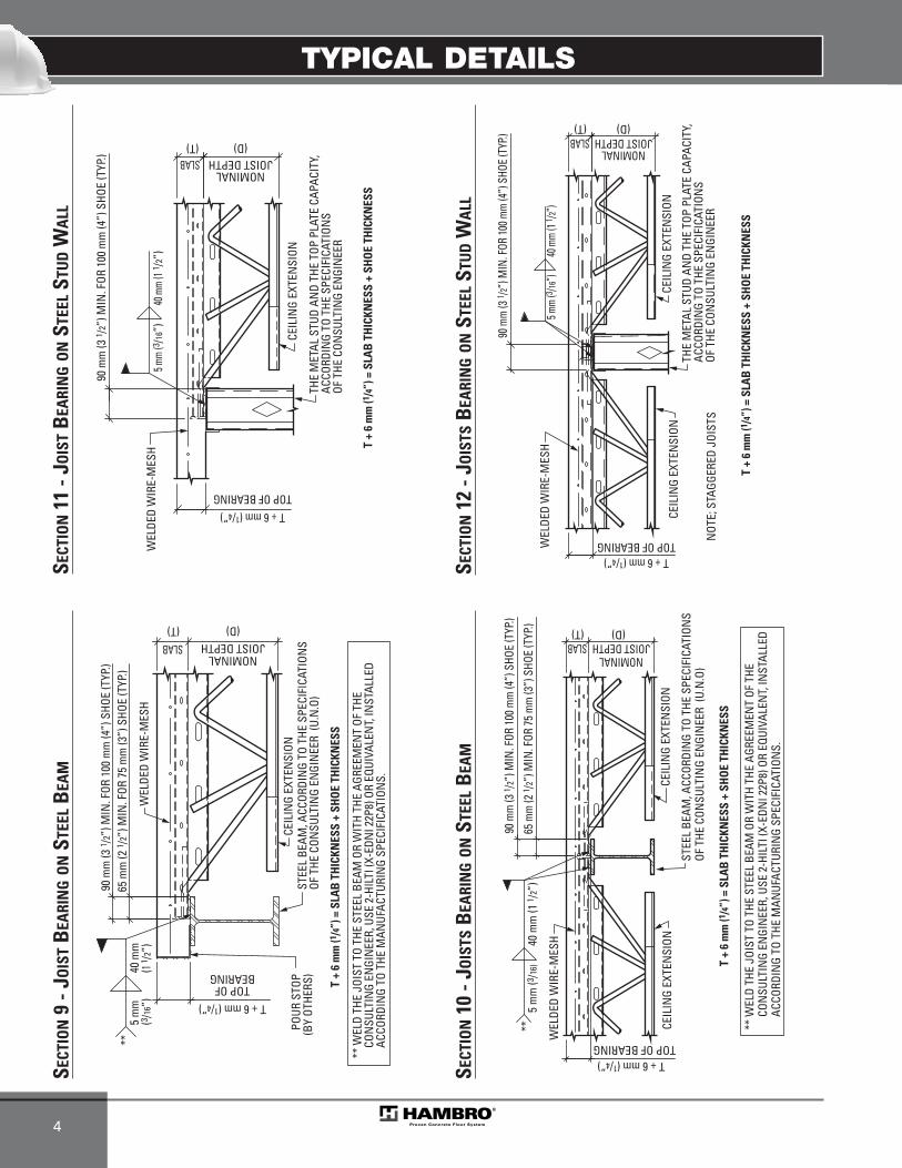
TYPICAL DETAILS
4
T +
6 m
m (1
/4”)
= S
LAB
TH
ICKN
ESS
+ SH
OE
THIC
KNES
S
T + 6 mm (1/4”)
TOP OF BEARING
NOMINALJOIST DEPTH
(D)
CEIL
ING
EXTE
NSI
ON
WEL
DED
WIR
E-M
ESH
5 mm
(3 /16
”)
40 m
m (1
1 /2”)
SLAB(T)
90 m
m (3
1 /2”
) MIN
. FOR
100
mm
(4”)
SHO
E (T
YP.)
THE
MET
AL S
TUD
AND
THE
TOP
PLAT
E CA
PACI
TY,
ACCO
RDIN
G TO
THE
SPE
CIFI
CATI
ONS
OF T
HE C
ONSU
LTIN
G EN
GIN
EER
T +
6 m
m (1
/4”)
= S
LAB
TH
ICKN
ESS
+ SH
OE
THIC
KNES
S
T + 6 mm (1/4”)TOP OF BEARING
CEIL
ING
EXTE
NSI
ON
NOMINALJOIST DEPTH
(D)
CEIL
ING
EXTE
NSI
ON
WEL
DED
WIR
E-M
ESH
5 mm
(3 /16”
)40
mm
(1 1 /2
”)
SLAB(T)
90 m
m (3
1 /2”)
MIN
. FOR
100 m
m (4
”) S
HOE
(TYP
.)
THE
MET
AL S
TUD
AND
THE
TOP
PLAT
E CA
PACI
TY,
ACCO
RDIN
G TO
THE
SPE
CIFI
CATI
ONS
OF T
HE C
ONSU
LTIN
G EN
GIN
EER
NOT
E; S
TAGG
ERED
JOI
STS
SECT
ION
11 -
JOIS
TB
EARI
NG
ON
STEE
LST
UD
WA
LL
SECT
ION
12 -
JOIS
TSB
EARI
NG
ON
STEE
LST
UD
WA
LL
WEL
DED
WIR
E-M
ESH
JOIST DEPTH(D)(T)
CEIL
ING
EXTE
NSI
ON
T +
6 m
m (1
/4”)
= S
LAB
TH
ICKN
ESS
+ SH
OE
THIC
KNES
S
STEE
L BE
AM, A
CCOR
DIN
G TO
THE
SPE
CIFI
CATI
ONS
OF T
HE C
ONSU
LTIN
G EN
GIN
EER
(U.N
.O)
NOMINALSLAB
65 m
m (2
1 /2”
) MIN
. FOR
75
mm
(3”)
SHO
E (T
YP.)
90 m
m (3
1 /2”
) MIN
. FOR
100
mm
(4”)
SHO
E (T
YP.)
TOP OFBEARING
T + 6 mm (1/4”)
40 m
m
(1 1 /
2”)
5 m
m(3 /
16”)
POUR
STO
P(B
Y OT
HERS
)
** W
ELD
THE
JOIS
T TO
THE
STE
EL B
EAM
OR
WIT
H TH
E AG
REEM
ENT
OF T
HE
CON
SULT
ING
ENGI
NEE
R, U
SE 2
-HIL
TI (X
-EDN
I 22P
8) O
R EQ
UIVA
LEN
T, IN
STAL
LED
A
CCOR
DIN
G TO
THE
MAN
UFAC
TURI
NG
SPEC
IFIC
ATIO
NS.
** WEL
DED
WIR
E-M
ESH
(D)(T)
CEIL
ING
EXTE
NSI
ON
T +
6 m
m (1
/4”)
= S
LAB
TH
ICKN
ESS
+ SH
OE
THIC
KNES
S
CEIL
ING
EXTE
NSI
ON
STEE
L BE
AM, A
CCOR
DIN
G TO
THE
SPE
CIFI
CATI
ONS
OF T
HE C
ONSU
LTIN
G EN
GIN
EER
(U.N
.O)
NOMINALJOIST DEPTHSLAB
T + 6 mm (1/4”)
65 m
m (2
1 /2”
) MIN
. FOR
75
mm
(3”)
SHO
E (T
YP.)
90 m
m (3
1 /2”
) MIN
. FOR
100
mm
(4”)
SHO
E (T
YP.)
40 m
m (1
1 /2”
)**
5 m
m (3
/16)
TOP OF BEARING
** W
ELD
THE
JOIS
T TO
THE
STE
EL B
EAM
OR
WIT
H TH
E AG
REEM
ENT
OF T
HE
CON
SULT
ING
ENGI
NEE
R, U
SE 2
-HIL
TI (X
-EDN
I 22P
8) O
R EQ
UIVA
LEN
T, IN
STAL
LED
A
CCOR
DIN
G TO
THE
MAN
UFAC
TURI
NG
SPEC
IFIC
ATIO
NS.
SECT
ION
9 - J
OIS
TB
EARI
NG
ON
STEE
LB
EAM
SECT
ION
10 -
JOIS
TSB
EARI
NG
ON
STEE
LB
EAM
MEP-Technical Manual CDN 0408.qxd 08/04/2009 18:06 Page 58

TYPICAL DETAILS
5
WEL
DED
WIR
E-M
ESH
NOMINALJOIST DEPTH
CEIL
ING
EXTE
NSI
ON
T +
6 m
m (1
/4”)
= S
LAB
TH
ICKN
ESS
+ SH
OE
THIC
KNES
S
(D)SLAB(T)
TOP OF BEARING
90 m
m (3
1 /2”
) MIN
. FOR
100
mm
(4”)
SHO
E (T
YP.)
40 m
m (1
1 /2”)
5 mm
(3 /16
”)
OF T
HE C
ONSU
LTIN
G EN
GIN
EER
ACCO
RDIN
G TO
THE
SPE
CIFI
CATI
ONS
THE
MET
AL S
TUD
AND
THE
TOP
PLAT
E CA
PACI
TY,
T + 6 mm (1/4”)
SECT
ION
13 -
JOIS
TB
EARI
NG
ON
AN
EXTE
RIO
RST
EEL
STU
DW
ALL
SLAB
JOIS
T SH
OE A
NCH
ORED
TO
PLAN
K W
ITH
SCRE
WS
OR N
AILS
T +
6 m
m (1
/4”)
= S
LAB
TH
ICKN
ESS
+ SH
OE
THIC
KNES
S
THE
WOO
D W
ALL
AND
THE
TOP
PLAT
E CA
PACI
TY,
ACCO
RDIN
G TO
THE
SPE
CIFI
CATI
ONS
OF T
HE C
ONSU
LTIN
G EN
GIN
EER
T + 6 mm (1/4”)
TOP OF BEARING
CEIL
ING
EXTE
NSI
ON
NOMINALJOIST DEPTH
WEL
DED
WIR
E-M
ESH
90 m
m (3
1 /2”
) MIN
. FOR
100
mm
(4”)
SHO
E (T
YP.)
(D)(T)
SECT
ION
14 -
JOIS
TB
EARI
NG
ON
AW
OO
DST
UD
WA
LL
NOMINALJOIST DEPTH
CEIL
ING
EXTE
NSI
ON
NOT
E; S
TAGG
ERED
JOI
STS
T +
6 m
m (1
/4”)
= S
LAB
TH
ICKN
ESS
+ SH
OE
THIC
KNES
S
CEIL
ING
EXTE
NSI
ON
THE
WOO
D W
ALL
AND
THE
TOP
PLAT
E CA
PACI
TY, A
CCOR
DIN
G TO
THE
SP
ECIF
ICAT
ION
S OF
THE
CO
NSU
LTIN
G EN
GIN
EER
(D)
JOIS
T SH
OE A
NCH
ORED
TO
PLAN
KW
ITH
SCRE
WS
OR N
AILS
WEL
DED
WIR
E-M
ESH
TOP OF BEARINGT + 6 mm (1/4”)
90 m
m (3
1/2
”) M
IN. F
OR 1
00 m
m (4
”) S
HOE
(TYP
.)
SLAB(T)
SECT
ION
15 -
JOIS
TSB
EARI
NG
ON
AW
OO
DST
UD
WA
LL
TOP OF BEARING
WEL
DED
WIR
E-M
ESH
NOMINALJOIST DEPTH
(D)(T)
CEIL
ING
EXTE
NSI
ON
T +
6 m
m (1 /4
”) =
SLA
B T
HIC
KNES
S +
SHO
E TH
ICKN
ESS
TEM
PORA
RY S
UPPO
RT U
NDER
EACH
JOIS
T AND
EA
CH EN
D UN
TIL A
LL FL
OORS
HAV
E BEE
N PO
URED
.(P
ROVI
DED
AND
DESI
GNED
BY O
THER
S)
ANGL
E AN
CHOR
ED T
O TH
E M
ASON
RY
WAL
L ACC
ORDI
NG T
O TH
E SP
ECIF
ICAT
IONS
OF T
HE
CONS
ULTI
NG E
NGIN
EER
SUPP
ORT
ANGL
E, A
CCOR
DING
TO
THE
SPEC
IFIC
ATIO
NS O
F THE
CON
SULT
ING
ENGI
NEER
.
FIBR
E BO
ARD
12 m
m (1 /2
”)
SOLI
D M
ASON
RY W
ALL,
ACCO
RDIN
G TO
THE
SPEC
IFIC
ATIO
NS O
F THE
CONS
ULTI
NG E
NGIN
EER
DO N
OT W
ELD
THE
SHOE
ON
THE
AN
GLE
REBA
R (IF
REQ
UIRE
D BY
THE
CONS
ULTI
NG E
NGIN
EER)
ACCO
RDIN
G TO
THE
SPE
CIFI
CATI
ONS
OF T
HE C
ONSU
LTIN
G EN
GIN
EER
T + 6 mm (1/4”)
SLAB
SECT
ION
16 -
EXPA
NSIO
NJO
INT
ATIN
TERM
EDIA
TEFL
OOR
(MAS
ONRY
WAL
L)
MEP-Technical Manual CDN 0408.qxd 08/04/2009 18:06 Page 59

TYPICAL DETAILS
6
WEL
DED
WIR
E-M
ESH
(D)(T)
CEIL
ING
EXTE
NSI
ON
SOLI
D M
ASON
RY W
ALL,
ACC
ORDI
NG
TO T
HE S
PECI
FICA
TION
SOF
THE
CON
SULT
ING
ENGI
NEE
R(F
ILL
THE
MAS
ONRY
BLO
CK W
ITH
MOR
TAR,
UN
DER
THE
JOIS
T SH
OE)
T +
6 m
m (1
/4”)
= S
LAB
TH
ICKN
ESS
+ SH
OE
THIC
KNES
S
CEIL
ING
EXTE
NSI
ON
FIBR
E BO
ARD
12 m
m (1
/2”)
DO N
OT W
ELD
THE
SHOE
ON
EM
BEDE
D M
ATER
IAL
12 m
m (1
/2”) Ø
ROD
x 6
00 m
m (2
4”)
@ 6
00 m
m (2
4”)c
/cGR
EASE
OR
WRA
P TH
IS E
ND
OF R
OD W
ITH
BUIL
DIN
G PA
PER
T + 6 mm (1/4”)
NOMINALJOIST DEPTHSLAB
TOP OF BEARING90
mm
(31 /2
”) M
IN. F
OR 1
00 m
m (4
”) S
HOE
(TYP
.)
REBA
R (IF
REQ
UIRE
D BY
THE
CON
SULT
ING
ENGI
NEE
R)
SECT
ION
17 -
EXPA
NSI
ON
JOIN
TAT
ROO
F(M
ASO
NRY
WA
LL)
DO N
OT W
ELD
THE
SHOE
ON
THE
ANGL
E (D)(T)
CEIL
ING
EXTE
NSI
ON
T +
6 m
m (1
/4”)
= S
LAB
TH
ICKN
ESS
+ SH
OE
THIC
KNES
S
CEIL
ING
EXTE
NSI
ONST
EEL
BEAM
, ACC
ORDI
NG
TO T
HE S
PECI
FICA
TION
S OF
THE
CON
SULT
ING
ENGI
NEE
R
WEL
DED
WIR
E-M
ESH
SUPP
ORT
ANGL
E, A
CCOR
DIN
G TO
THE
SPE
CIFI
CATI
ONS
OF T
HE
CON
SULT
ING
ENGI
NEE
R (U
.N.O
)
FIBR
E BO
ARD
12 m
m (1
/2”)
** W
ELD
THE
JOIS
T TO
THE
STE
EL B
EAM
OR
WIT
H TH
E AG
REEM
ENT
OF T
HE
CON
SULT
ING
ENGI
NEE
R, U
SE 2
-HIL
TI (X
-EDN
I 22P
8) O
R EQ
UIVA
LEN
T, IN
STAL
LED
A
CCOR
DIN
G TO
THE
MAN
UFAC
TURI
NG
SPEC
IFIC
ATIO
NS.
STIF
FEN
ERST
IFFE
NER
(IF R
EQUI
RED)
(IF R
EQUI
RED)
STIF
FEN
ER(IF
REQ
UIRE
D)
**65
mm
(2 1 /
2”) M
IN. F
OR 7
5 m
m (3
”) S
HOE
(TYP
.)90
mm
(3 1 /
2”) M
IN. F
OR 1
00 m
m (4
”) S
HOE
(TYP
.)
5 m
m (3
/16”)
40 m
m (1
1 /2”
)
T + 6 mm (1/4”)TOP OF BEARING
NOMINALJOIST DEPTHSLAB
SECT
ION
18 -
EXPA
NSI
ON
JOIN
TAT
INTE
RMED
IATE
FLO
OR
(STE
ELB
EAM
)
DO N
OT W
ELD
THE
SHOE
ON
THE
BEA
M
CEIL
ING
EXTE
NSI
ON
T +
6 m
m (1
/4”)
= S
LAB
TH
ICKN
ESS
+ SH
OE
THIC
KNES
S
CEIL
ING
EXTE
NSI
ONST
EEL
BEAM
, ACC
ORDI
NG
TO T
HE S
PECI
FICA
TION
S OF
TH
E CO
NSU
LTIN
G EN
GIN
EER
(U.N
.O)
WEL
DED
WIR
E-M
ESH
FIBR
E BO
ARD
12 m
m (1
/2”)
** W
ELD
THE
JOIS
T TO
THE
STE
EL B
EAM
OR
WIT
H TH
E AG
REEM
ENT
OF T
HE
CON
SULT
ING
ENGI
NEE
R, U
SE 2
-HIL
TI (X
-EDN
I 22P
8) O
R EQ
UIVA
LEN
T, IN
STAL
LED
A
CCOR
DIN
G TO
THE
MAN
UFAC
TURI
NG
SPEC
IFIC
ATIO
NS.
**
65 m
m (2
1 /2”
) MIN
. FOR
75
mm
(3”)
SHO
E (T
YP.)
90 m
m (3
1 /2”
) MIN
. FOR
100
mm
(4”)
SHO
E (T
YP.)
12 m
m (1
/2”) Ø
ROD
x 6
00 m
m (2
4”)
@ 6
00 m
m (2
4”)c
/c.
GREA
SE O
R W
RAP
THIS
EN
DOF
ROD
, WIT
H BU
ILDI
NG
PAPE
R
5 m
m (3
/16”)
40 m
m (1
1 /2”
)
T + 6 mm (1/4”)TOP OF BEARING
NOMINALJOIST DEPTH
(D)SLAB(T)
SECT
ION
19 -
EXPA
NSI
ON
JOIN
TAT
ROO
F(S
TEEL
BEA
M)
(T)
WEL
DED
WIR
E-M
ESH
DIAM
ETER
� 20
0 mm
(8”)
**REBA
R ARO
UND T
HE HO
LE IS N
OT REQ
UIRED
**THE
QUAN
TITY O
F HOL
E AT 6
” AND
MOR
E O
F THE
JOIST
IS NO
T IMP
ORTA
NT
SLAB
150 m
m (6”
)OP
ENIN
GSE
E TYP
ICAL
REIN
FORC
EMEN
TFO
R SLA
B OPE
NING
.
150 m
m (6”
)
(D)
NOMINAL JOIST DEPTH
MIN
.M
IN.
END
OFSL
AB
150 m
m (6”
)M
IN.
( 3/4”) 19 mm(APPLICABLE
AT EACH CASE)
( 3/4”) 19 mm(APPLICABLE
AT EACH CASE)
HOLE
HO
LE
HOLE
SECT
ION
20 -
MIN
IMU
MCL
EARA
NCE
FOR
OPE
NIN
GA
ND
HO
LEIN
THE
SLAB
MEP-Technical Manual CDN 0408.qxd 08/04/2009 18:06 Page 60
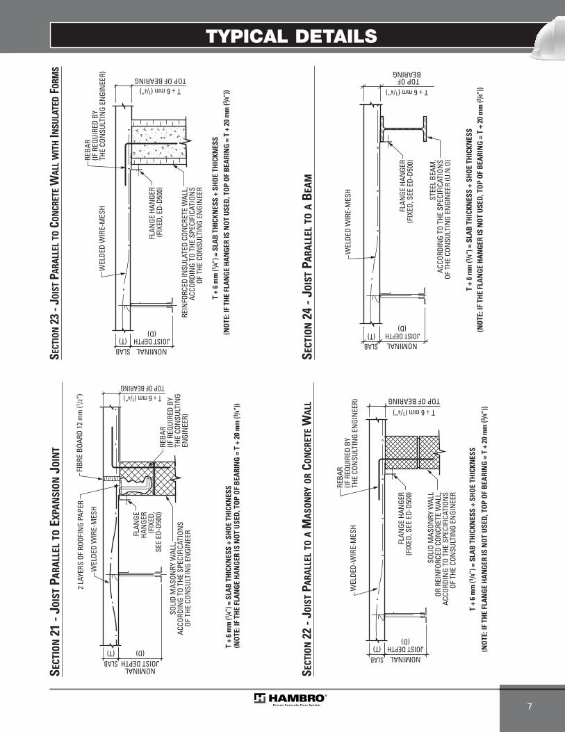
TYPICAL DETAILS
7
TOP OF BEARING
WEL
DED-
WIR
E-M
ESH
T +
6 m
m (1
/4”)
= S
LAB
TH
ICKN
ESS
+ SH
OE
THIC
KNES
S
FLAN
GE H
ANGE
R(F
IXED
, SEE
ED-
D500
)
T + 6 mm (1/4”)
REBA
R(IF
REQ
UIRE
D BY
THE
CON
SULT
ING
ENGI
NEE
R)
(T)SLAB
(NO
TE: I
F TH
E FL
AN
GE
HA
NG
ER IS
NO
T U
SED
, TO
P O
F B
EARI
NG
= T
+ 2
0 m
m (3
/4”)
)
SOLI
D M
ASON
RY W
ALL
OR R
EIN
FORC
ED C
ONCR
ETE
WAL
L,AC
CORD
ING
TO T
HE S
PECI
FICA
TION
SOF
THE
CON
SULT
ING
ENGI
NEE
R
JOIST DEPTHNOMINAL
(D)
SECT
ION
22 -
JOIS
TPA
RALL
ELTO
AM
ASO
NRY
OR
CON
CRET
EW
ALL
FLAN
GE H
ANGE
R(F
IXED
, ED-
D500
)
REIN
FORC
ED IN
SULA
TED
CON
CRET
E W
ALL,
ACCO
RDIN
G TO
THE
SPE
CIFI
CATI
ONS
OF T
HE C
ONSU
LTIN
G EN
GIN
EER
T +
6 m
m (1 /4
”) =
SLA
B T
HIC
KNES
S +
SHO
E TH
ICKN
ESS
WEL
DED
WIR
E-M
ESH
REBA
R(IF
REQ
UIRE
D BY
THE
CON
SULT
ING
ENGI
NEE
R) TOP OF BEARINGT + 6 mm (1/4”)
(T)SLAB
(NO
TE: I
F TH
E FL
AN
GE
HA
NG
ER IS
NO
T U
SED
, TO
P O
F B
EARI
NG
= T
+ 2
0 m
m (3 /4
”))
JOIST DEPTHNOMINAL
(D)
SECT
ION
23 -
JOIS
TPA
RALL
ELTO
CON
CRET
EW
ALL
WIT
HIN
SULA
TED
FORM
S
T + 6 mm (1/4”)
WEL
DED
WIR
E-M
ESH
T +
6 m
m (1 /4
”) =
SLA
B T
HIC
KNES
S +
SHO
E TH
ICKN
ESS
STEE
L BE
AM,
ACCO
RDIN
G TO
THE
SPE
CIFI
CATI
ONS
OF T
HE C
ONSU
LTIN
G EN
GIN
EER
(U.N
.O)
FLAN
GE H
ANGE
R(F
IXED
, SEE
ED-
D500
)
TOP OF BEARING
SLAB(T) (N
OTE
: IF
THE
FLA
NG
E H
AN
GER
IS N
OT
USE
D, T
OP
OF
BEA
RIN
G =
T +
20
mm
(3 /4”)
)
NOMINALJOIST DEPTH
(D)
SECT
ION
24 -
JOIS
TPA
RALL
ELTO
AB
EAM
WEL
DED
WIR
E-M
ESH
T +
6 m
m (1 /4
”) =
SLA
B T
HIC
KNES
S +
SHO
E TH
ICKN
ESS
(NO
TE: I
F TH
E FL
AN
GE
HA
NG
ER IS
NO
T U
SED
, TO
P O
F B
EARI
NG
= T
+ 2
0 m
m (3 /4
”))
FIBR
E BO
ARD
12 m
m (1
/2”)
SOLI
D M
ASON
RY W
ALL,
ACCO
RDIN
G TO
THE
SPE
CIFI
CATI
ONS
OF T
HE C
ONSU
LTIN
G EN
GIN
EERFL
ANGE
HAN
GER
(FIX
ED,
SEE
ED-D
500)
2 LA
YERS
OF
ROOF
ING
PAPE
R
REBA
R(IF
REQ
UIRE
D BY
THE
CON
SULT
ING
ENGI
NEE
R)
NOMINALJOIST DEPTH
(D)SLAB(T)
T + 6 mm (1/4”)TOP OF BEARING
SECT
ION
21 -
JOIS
TPA
RALL
ELTO
EXPA
NSI
ON
JOIN
T
MEP-Technical Manual CDN 0408.qxd 08/04/2009 18:06 Page 61
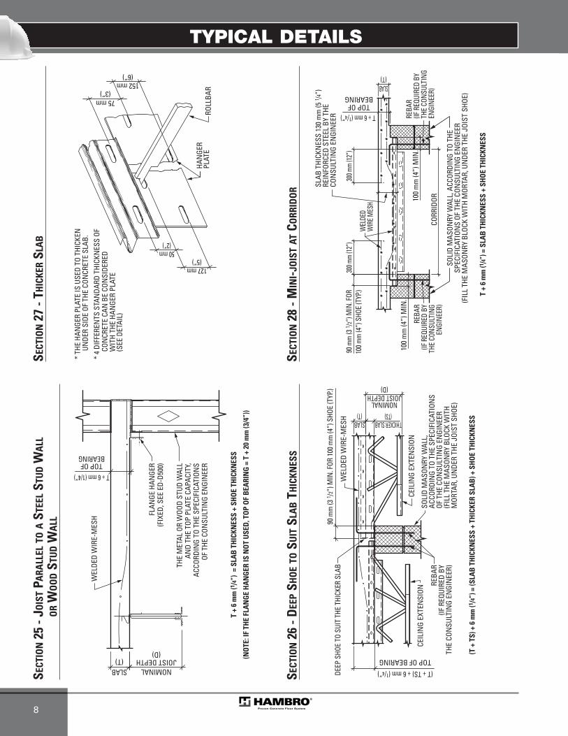
TYPICAL DETAILS
8
75 mm(3”)
152 mm(6”)
127 mm(5”)
50 mm(2”)
ROLL
BAR
HAN
GER
PLAT
E
UNDE
R SI
DE O
F TH
E CO
NCR
ETE
SLAB
.*
THE
HAN
GER
PLAT
E IS
USE
D TO
THI
CKEN
* 4
DIFF
EREN
TS S
TAN
DARD
THI
CKN
ESS
OF
WIT
H TH
E HA
NGE
R PL
ATE
CON
CRET
E CA
N B
E CO
NSI
DERE
D
(SEE
DET
AIL)
SECT
ION
27 -
THIC
KER
SLA
B
THE
MET
AL O
R W
OOD
STUD
WAL
LAN
D TH
E TO
P PL
ATE
CAPA
CITY
,AC
CORD
ING
TO T
HE S
PECI
FICA
TION
SOF
THE
CON
SULT
ING
ENGI
NEE
R
FLAN
GE H
ANGE
R(F
IXED
, SEE
ED-
D500
)
WEL
DED
WIR
E-M
ESH
T +
6 m
m (1
/4”)
= S
LAB
TH
ICKN
ESS
+ SH
OE
THIC
KNES
S
(T)SLAB
TOP OFT + 6 mm (1/4”)
BEARING
(NO
TE: I
F TH
E FL
AN
GE
HA
NG
ER IS
NO
T U
SED
, TO
P O
F B
EARI
NG
= T
+ 2
0 m
m (3
/4”)
)
JOIST DEPTHNOMINAL
(D)
SECT
ION
25 -
JOIS
TPA
RALL
ELTO
AST
EEL
STU
DW
ALL
OR
WO
OD
STU
DW
ALL
WEL
DED
WIR
E-M
ESH
JOIST DEPTH(D)
(T)
SOLI
D M
ASON
RY W
ALL,
ACCO
RDIN
G TO
THE
SPE
CIFI
CATI
ONS
OF T
HE C
ONSU
LTIN
G EN
GIN
EER
(FIL
L TH
E M
ASON
RY B
LOCK
WIT
H M
ORTA
R, U
NDE
R TH
E JO
IST
SHOE
)
(T +
TS)
+ 6
mm
(1/4
”) =
(SLA
B T
HIC
KNES
S +
THIC
KER
SLA
B) +
SH
OE
THIC
KNES
S
CEIL
ING
EXTE
NSI
ON
DEEP
SHO
E TO
SUI
T TH
E TH
ICKE
R SL
AB
CEIL
ING
EXTE
NSI
ON
SLAB
TOP OF BEARING
NOMINAL90
mm
(3 1 /
2”) M
IN. F
OR 1
00 m
m (4
”) S
HOE
(TYP
.)
(T + TS) + 6 mm (1/4”)
(TS)THICKER SLAB
REBA
R(IF
REQ
UIRE
D BY
THE
CON
SULT
ING
ENGI
NEE
R)
SECT
ION
26 -
DEE
PSH
OE
TOSU
ITSL
AB
THIC
KNES
S
TOP OF
(T)
CORR
IDOR
SOLI
D M
ASON
RY W
ALL,
ACC
ORDI
NG
TO T
HESP
ECIF
ICAT
ION
S OF
THE
CON
SULT
ING
ENGI
NEE
R(F
ILL
THE
MAS
ONRY
BLO
CK W
ITH
MOR
TAR,
UN
DER
THE
JOIS
T SH
OE)
90 m
m (3
1 /2”)
MIN
. FOR
T + 6 mm (1/4”)
BEARING
300 m
m (12
”)30
0 mm
(12”)
100 m
m (4
”) S
HOE
(TYP
.) T +
6 m
m (1 /4
”) =
SLA
B T
HIC
KNES
S +
SHO
E TH
ICKN
ESS
REBA
R(IF
REQ
UIRE
D BY
THE
CON
SULT
ING
ENGI
NEER
)
SLAB
100
mm
(4”)
MIN
.
100
mm
(4”)
MIN
.RE
BAR
(IF R
EQUI
RED
BYTH
E CO
NSUL
TING
ENGI
NEER
)
WEL
DED
WIR
E MES
H
SLAB
THI
CKN
ESS
130
mm
(5 1 /4
”)RE
INFO
RCED
STE
EL B
Y TH
ECO
NSU
LTIN
G EN
GIN
EER
SECT
ION
28 -
MIN
I-JO
IST
ATCO
RRID
OR
MEP-Technical Manual CDN 0408.qxd 08/04/2009 18:06 Page 62
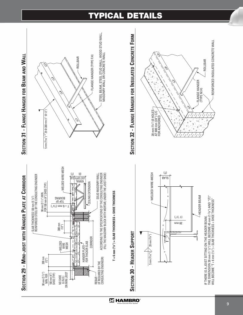
TYPICAL DETAILS
9
TOP OFBEARING
(D)(T)
CEILI
NG EX
TENS
ION
CORR
IDOR
SOLID
MAS
ONRY
WAL
L,AC
CORD
ING
TO TH
E SPE
CIFIC
ATIO
NS O
F THE
CON
SULT
ING
ENGI
NEER
(FILL
THE M
ASON
RY B
LOCK
WIT
H M
ORTA
R, U
NDER
THE J
OIST
SHO
E)
HANG
ER P
LATE
FOR
THIC
KER
SLAB
WEL
DED
WIR
EM
ESH
90 m
m (3
1 /2”)
MIN
. FOR
T + 6 mm (1/4”)
300 m
m(12
”)
300 m
m(12
”)10
0 mm
(4”)
SHOE
(TYP
.)
T +
6 m
m (1
/4”)
= S
LAB
TH
ICKN
ESS
+ SH
OE
THIC
KNES
S
WEL
DED
WIR
E-M
ESH
REBA
R(IF
REQ
UIRE
D BY
THE
CONS
ULTI
NG EN
GINE
ER)
90 m
m (3
1 / 2”
) MIN
.FO
R 10
0 mm
(4”) S
HOE (
TYP.)
SLABNOMINAL
JOIST DEPTH
SLAB
THIC
KNES
S 13
0 mm
(5 1 /4
”)RE
INFO
RCED
STE
EL B
Y THE
CON
SULT
ING
ENGI
NEER
NO S
HOE
(U.N
.O.)
ON M
INI J
OIST
SECT
ION
29 -
MIN
I-JO
IST
WIT
HH
AN
GER
PLAT
EAT
CORR
IDO
R
(T)
WEL
DED
WIR
E-M
ESH
HEAD
ER B
EAM
IF T
HERE
IS A
JOI
ST S
ITTI
NG
ON T
HE H
EADE
R BE
AM,
THE
DIM
ENSI
ON 3
9 m
m (1
1 /2”)
WIL
L BE
COM
E 45
mm
(1 3 /4
”) A
ND
“(T)
”W
ILL
BECO
ME
“T +
6 m
m (1 /4
”) =
SLA
B TH
ICKN
ESS
+ SH
OE T
HICK
NES
S”
SLAB
39 mm
5 mm
(3 /16”
)20
mm
(3 /4”)
(1 1/2”)
SECT
ION
30 -
HEA
DER
SUPP
ORT
FLAN
GE H
ANGE
R (T
YPE
F.H)
ROLL
BAR
STEE
L BE
AM, S
TEEL
STU
D W
ALL,
WOO
D ST
UD W
ALL,
MAS
ONRY
WAL
L OR
CON
CRET
E W
ALL
25 @
300 m
m (1”
@ 12
”)5 m
m (3 /1
6”)
SECT
ION
31 -
FLA
NG
EH
AN
GER
FOR
BEA
MA
ND
WA
LL
FLAN
GE H
ANGE
R(T
YPE
M.H
)RO
LLBA
R
20 m
m (3 /4
”) Ø
HOL
ESAT
600
mm
(24”
) C/C
FOR
ANCH
ORED
REIN
FORC
ED IN
SULA
TED
CON
CRET
E W
ALL
SECT
ION
32 -
FLA
NG
EH
AN
GER
FOR
INSU
LATE
DCO
NCR
ETE
FORM
MEP-Technical Manual CDN 0408.qxd 08/04/2009 18:06 Page 63

TYPICAL DETAILS
10
TEM
PORA
RY S
UPPO
RTFO
R BA
LCON
Y(D
ESIG
NED
AN
D SU
PPLI
EDBY
OTH
ERS)
WEL
DED
WIR
E-M
ESH
SLOP
E
IMPO
RTAN
T;BR
IDGI
NG
ANGL
ES T
O BE
INST
ALLE
D AF
TER
FORM
S ST
RIPP
ED B
UTBE
FORE
THE
REM
OVAL
OF
BALC
ONY
TEM
PORA
RY S
UPPO
RTS
HANG
ER P
LATE
TO TH
ICKE
N SL
ABM
ORE 5
0 (2”
), 76 (
3”), 1
27 (5
”)OR
152 (
6”) T
HAN
BASE
SLA
B
FLAN
GE H
ANGE
R
SEE
SPEC
IFIC
ATIO
NS O
F THE
ARC
HITE
CT
REBA
R AC
CORD
ING
TO
THE
SPEC
IFIC
ATIO
NS
OF
THE
CON
SULT
ING
ENGI
NEE
R
25 mm (1”)
VARI
ABLE
1251
mm
(4’-1
1 /4”)
(T)
BRID
GIN
G TO
BOT
TOM
CHO
RD M
AY B
E N
ECES
SARY
IF U
PLIF
T DU
E TO
CAN
TILE
VER
BALC
ONY
EXCE
EDS
GRAV
ITY
LOAD
. (IF
REQ
UIRE
D BY
THE
EN
GIN
EER)
SLABNOMINAL
JOIST DEPTH(D)
REBA
R(IF
REQ
UIRE
D BY
THE
CON
SULT
ING
ENGI
NEE
R)
SOLI
D M
ASON
RY W
ALL,
ACCO
RDIN
G TO
THE
SPE
CIFI
CATI
ONS
OF T
HE C
ONSU
LTIN
G EN
GINE
ER(T)
TEM
PORA
RY S
UPPO
RT FO
R BA
LCON
Y(D
ESIG
NED
AND
SUPP
LIED
BY O
THER
S)
REBA
R AC
CORD
ING
TO
THE
SPEC
IFIC
ATIO
NS
OF
THE
CON
SULT
ING
ENGI
NEE
RW
ELDE
D W
IRE-
MES
H
BRID
GIN
G TO
BOT
TOM
CHO
RD M
AY B
E N
ECES
SARY
IF U
PLIF
T DU
E TO
CAN
TILE
VER
BALC
ONY
EXCE
EDS
GRAV
ITY
LOAD
. (IF
REQ
UIRE
D BY
THE
EN
GIN
EER)
OF 50 mm (2”)TOP OF BEARING
SLOP
E
IMPO
RTAN
T;BR
IDGI
NG
ANGL
ES T
O BE
INST
ALLE
D AF
TER
FORM
S ST
RIPP
ED B
UTBE
FORE
THE
REM
OVAL
OF
BALC
ONY
TEM
PORA
RY S
UPPO
RTS
FLAN
GE H
ANGE
R
REBA
R(IF
REQ
UIRE
D BY
THE
CON
SULT
ING
ENGI
NEE
R)
SOLI
D M
ASON
RY W
ALL,
ACCO
RDIN
G TO
THE
SPE
CIFI
CATI
ONS
OF T
HE C
ONSU
LTIN
G EN
GINE
ER
SLAB
T + 50 mm (2”) JOIST SHORTER
25 mm (1”)
SEE
SPEC
IFIC
ATIO
NS
OF T
HE A
RCHI
TECT
VARI
ABLE
1251
mm
(4’-1
1 /4”)
NOMINALJOIST DEPTH
(D)
SECT
ION
34 -
CAN
TILE
VERE
DB
ALC
ON
Y(J
OIS
TPA
RALL
ELTO
BA
LCO
NY)
SECT
ION
33 -
CAN
TILE
VERE
DB
ALC
ON
Y(S
HA
LLO
WJO
IST
PARA
LLEL
TOB
ALC
ON
Y)
MEP-Technical Manual CDN 0408.qxd 08/04/2009 18:06 Page 64
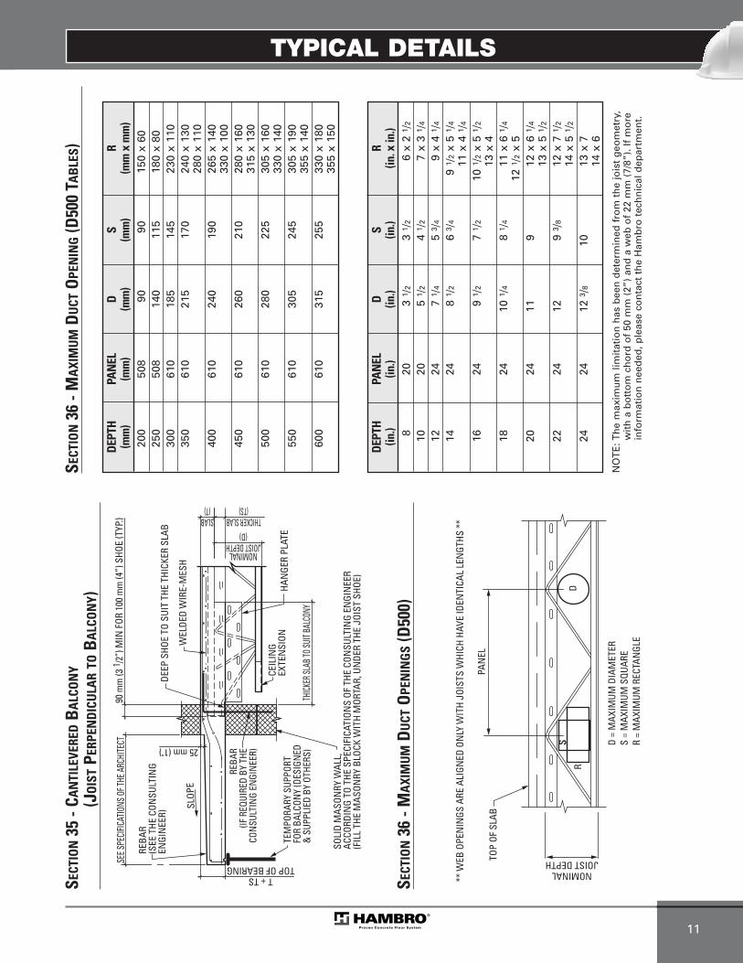
TYPICAL DETAILS
11
SLOP
E
TEM
PORA
RY S
UPPO
RTFO
R BA
LCON
Y (D
ESIG
NED
&
SUP
PLIE
D BY
OTH
ERS)
REBA
R(S
EE T
HE C
ONSU
LTIN
GEN
GIN
EER)
SLAB(T)
HAN
GER
PLAT
E
THICK
ER SL
AB TO
SUIT
BALC
ONY
DEEP
SHO
E TO
SUI
T TH
E TH
ICKE
R SL
AB
WEL
DED
WIR
E-M
ESH
REBA
R(IF
REQ
UIRE
D BY
THE
CON
SULT
ING
ENGI
NEE
R)
90 m
m (3
1/2
”) M
IN F
OR 1
00 m
m (4
”) S
HOE
(TYP
.)
SOLI
D M
ASON
RY W
ALL,
ACCO
RDIN
G TO
THE
SPE
CIFI
CATI
ONS
OF T
HE C
ONSU
LTIN
G EN
GIN
EER
(FIL
L TH
E M
ASON
RY B
LOCK
WIT
H M
ORTA
R, U
NDE
R TH
E JO
IST
SHOE
)
CEIL
ING
EXTE
NSI
ON
T + TSTOP OF BEARING
25 mm (1")
NOMINALJOIST DEPTH
(D)THICKER SLAB
(TS)
SEE S
PECI
FICAT
IONS
OF T
HE A
RCHI
TECT
SECT
ION
35 -
CAN
TILE
VERE
DB
ALC
ON
Y(J
OIS
TPE
RPEN
DIC
ULA
RTO
BA
LCO
NY)
DSS D
= M
AXIM
UM D
IAM
ETER
R
S =
MAX
IMUM
SQU
ARE
R =
MAX
IMUM
REC
TAN
GLE
PAN
ELTO
P OF
SLA
B
NOMINALJOIST DEPTH
** W
EB O
PEN
INGS
ARE
ALI
GNED
ON
LY W
ITH
JOIS
TS W
HICH
HAV
E ID
ENTI
CAL
LEN
GTHS
**
SECT
ION
36 -
MA
XIM
UM
DU
CTO
PEN
ING
S(D
500)
SECT
ION
36 -
MA
XIM
UM
DU
CTO
PEN
ING
(D50
0 TA
BLE
S)
DEPT
HPA
NEL
D
S R
(in.)
(in.)
(in.)
(in.)
(in. x
in.)
820
3 1 /
23
1 /2
6 x
2 1 /
2
1020
5 1 /
24
1 /2
7 x
3 1 /
4
1224
7 1 /
45
3 /4
9 x
4 1 /
4
1424
8 1 /
26
3 /4
9 1 /
2x
5 1 /
4
11 x
4 1
/416
249
1 /2
7 1 /
210
1/2
x 5
1 /2
13 x
418
2410
1/4
8 1 /
411
x 6
1/4
12 1
/2x
520
2411
912
x 6
1/4
13 x
5 1
/222
2412
9 3 /
812
x 7
1/2
14 x
5 1
/224
2412
3/8
1013
x 7
14 x
6
DEPT
HPA
NEL
D
S R
(mm
)(m
m)
(mm
)(m
m)
(mm
x m
m)
200
508
9090
150
x 60
250
508
140
115
180
x 80
300
610
185
145
230
x 11
035
061
021
517
024
0 x
130
280
x 11
040
061
024
019
026
5 x
140
330
x 10
045
061
026
021
028
0 x
160
315
x 13
050
061
028
022
530
5 x
160
330
x 14
055
061
030
524
530
5 x
190
355
x 14
060
061
031
525
533
0 x
180
355
x 15
0
NO
TE
: Th
e m
axim
um
lim
itat
ion
has
bee
n d
eter
min
ed f
rom
th
e jo
ist
geo
met
ry,
wit
h a
bo
tto
m c
ho
rd o
f 50
mm
(2”
) an
d a
web
of
22 m
m (
7/8”
). If
mo
rein
form
atio
n n
eed
ed, p
leas
e co
nta
ct t
he
Ham
bro
tec
hn
ical
dep
artm
ent.
MEP-Technical Manual CDN 0408.qxd 08/04/2009 18:06 Page 65

TYPICAL DETAILS
12
MEP-Technical Manual CDN 0408.qxd 08/04/2009 18:06 Page 66
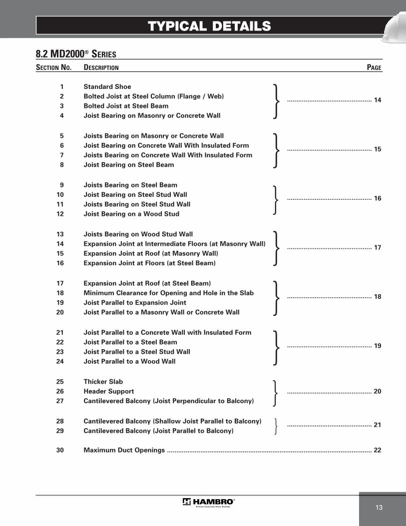
TYPICAL DETAILS
13
8.2 MD2000® SERIES
SECTION NO. DESCRIPTION PAGE
1 Standard Shoe
2 Bolted Joist at Steel Column (Flange / Web)
3 Bolted Joist at Steel Beam.............................................. 14
4 Joist Bearing on Masonry or Concrete Wall
5 Joists Bearing on Masonry or Concrete Wall
6 Joist Bearing on Concrete Wall With Insulated Form
7 Joists Bearing on Concrete Wall With Insulated Form.............................................. 15
8 Joist Bearing on Steel Beam
9 Joists Bearing on Steel Beam
10 Joist Bearing on Steel Stud Wall
11 Joists Bearing on Steel Stud Wall.............................................. 16
12 Joist Bearing on a Wood Stud
13 Joists Bearing on Wood Stud Wall
14 Expansion Joint at Intermediate Floors (at Masonry Wall)
15 Expansion Joint at Roof (at Masonry Wall) .............................................. 17
16 Expansion Joint at Floors (at Steel Beam)
17 Expansion Joint at Roof (at Steel Beam)
18 Minimum Clearance for Opening and Hole in the Slab
19 Joist Parallel to Expansion Joint.............................................. 18
20 Joist Parallel to a Masonry Wall or Concrete Wall
21 Joist Parallel to a Concrete Wall with Insulated Form
22 Joist Parallel to a Steel Beam
23 Joist Parallel to a Steel Stud Wall.............................................. 19
24 Joist Parallel to a Wood Wall
25 Thicker Slab
26 Header Support .............................................. 20
27 Cantilevered Balcony (Joist Perpendicular to Balcony)
28 Cantilevered Balcony (Shallow Joist Parallel to Balcony)
29 Cantilevered Balcony (Joist Parallel to Balcony) .............................................. 21
30 Maximum Duct Openings ............................................................................................................... 22
}}}
}}}}}
MEP-Technical Manual CDN 0408.qxd 08/04/2009 18:06 Page 67

TYPICAL DETAILS
14
NOMINALJOIST DEPTH
(D)
STEE
LDE
CK
SOLI
D M
ASON
RY W
ALL O
R RE
INFO
RCEM
ENT
CONC
RETE
WAL
L,AC
CORD
ING
TO T
HE S
PECI
FICA
TION
S OF
THE
CON
SULT
ING
ENGI
NEER
(FIL
L THE
MAS
ONRY
BLO
CK W
ITH
MOR
TAR,
UND
ER T
HE J
OIST
SHO
E)
CEIL
ING
EXTE
NSI
ON
T + 38 mm (1 1/2”)TOP OF BEARING
TOTALSLAB
NOMINALSLAB
(T)
90 m
m (3
1 /2”
) MIN
. FOR
100
mm
(4”)
SHO
E (T
YP.)
WEL
DED
WIR
E-M
ESH
REBA
R(IF
REQ
UIRE
D BY
THE
CO
NSU
LTIN
G EN
GIN
EER)
L 10
0 x
75 x
6 x
150
mm
(L 4
”x 3
”x 1 /
4”x
6”)
TOP
CHOR
D
TOP
OF S
LAB
FIRS
T DI
AGON
AL
100
mm
(4”)
TOTAL SLABT + 38 mm (1 1/2”)
NOMINALSLAB (T)
T +
38 m
m (1
1 /2”
) = N
OM
INA
L SL
AB
TH
ICKN
ESS
+ST
EEL
DEC
K D
EPTH
75 mm (3”)
6 mm (1/4”)
SECT
ION
4 - J
OIS
TB
EARI
NG
ON
MA
SON
RYO
RCO
NCR
ETE
WA
LL
SECT
ION
1 - S
TAN
DA
RDJO
IST
SHO
E
NOMINALSLAB
(T) TOTAL
T + 38 mm (1 1/2”)
100 m
m
65 m
m (2
1 /2”
)
21 x
32
mm
(13 /1
6” x
1 1 /
4”) S
LOTS
@ 1
25 m
m (5
”)c /
c (HA
MBR
O SH
OE)
21 m
m (1
3 /16”
)Ø H
OLES
@ 1
25 m
m (5
”)c /
c (SU
PPOR
T)
WEL
DED
WIR
E-M
ESH
TOP OF BEARING
NOMINALJOIST DEPTH
(D)SLAB
STEE
L DE
CK
STEE
L CO
LUM
N,
ACCO
RDIN
G TO
THE
SPE
CIFI
CATI
ONS
OF T
HE C
ONSU
LTIN
G EN
GIN
EER
(U.N
.O)
CEIL
ING
EXTE
NSI
ON
- SH
OE
WID
TH =
190
mm
(7 1 /
2”)
(4”)
90 m
m (3
1 /2”
) MIN
. FOR
100
mm
(4”)
SHO
E (T
YP.)
SECT
ION
2 - B
OLT
EDJO
IST
ATST
EEL
COLU
MN
(FLA
NG
E/ W
EB)
NOMINALJOIST DEPTH
(D)
STEE
L BE
AM, A
CCOR
DIN
G TO
THE
SPE
CIFI
CATI
ONS
OF T
HE C
ONSU
LTIN
G EN
GIN
EER
(U.N
.O)
CEIL
ING
EXTE
NSI
ON
TOP OF BEARING
WEL
DED
WIR
E-M
ESH
STEE
L DE
CK
21 x
32
mm
(13 /1
6”x
1 1 /4
”) S
LOTS
@ 1
25 m
m (5
”)c /
c (HA
MBR
O SH
OE)
21 m
m (1
3 /16”
)Ø H
OLES
@
125
mm
(5”)
c /c (
SUPP
ORT)
T + 38 mm (1 1/2”)
TOTALSLAB
NOMINALSLAB
(T)
58 m
m (2
1 /4”) F
LANG
E BET
WEE
N 10
0 mm
(4”) @
125 m
m (4
7 /8”)
70 m
m (2
3 /4”) F
LANG
E BET
WEE
N 12
7 mm
(5”) @
150 m
m (5
7 /8”)
102 m
m (4
”) F
LANG
E BET
WEE
N 15
2 mm
(6”) @
188 m
m (7
3 /8”)
127 m
m (5
”) F
LANG
E BET
WEE
N 19
0 mm
(7 1 /2”
) @ 22
8 mm
(8 7 /8”
)15
2 mm
(6”)
FLA
NGE B
ETW
EEN
230 m
m (9”
) @ 25
2 mm
(9 7 /8”
)20
3 mm
(8”)
FLA
NGE B
ETW
EEN
254 m
m (10
”) @
303 m
m (11
7 /8”)
230 m
m (9
”) F
LANG
E OF 3
05 m
m (12
”) AN
D M
ORE
CEIL
ING
EXTE
NSI
ON
SECT
ION
3 - B
OLT
EDJO
IST
ATST
EEL
BEA
M
MEP-Technical Manual CDN 0408.qxd 08/04/2009 18:06 Page 68
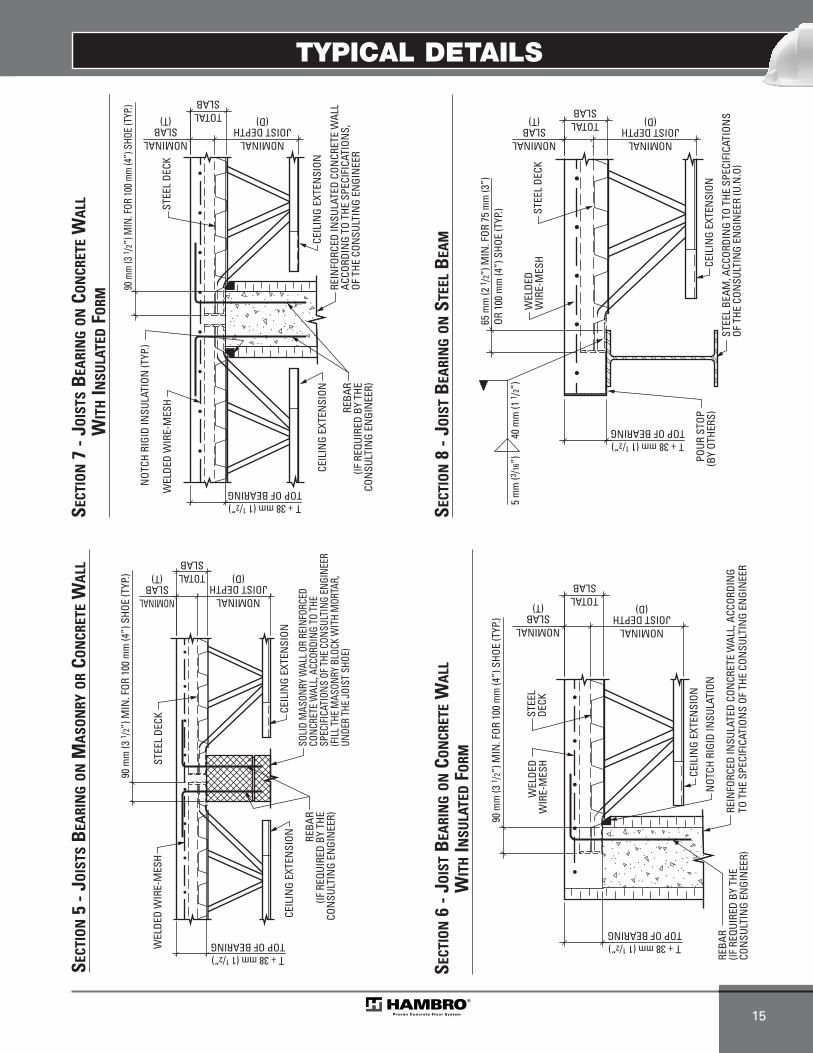
TYPICAL DETAILS
15
NOMINALJOIST DEPTH
(D)
STEE
LDE
CK
REIN
FORC
ED IN
SULA
TED
CON
CRET
E W
ALL,
ACC
ORDI
NG
TO T
HE S
PECI
FICA
TION
S OF
THE
CON
SULT
ING
ENGI
NEE
R
CEIL
ING
EXTE
NSI
ON
WEL
DED
WIR
E-M
ESH
T + 38 mm (1 1/2”)TOP OF BEARING
TOTALSLAB
NOMINALSLAB
(T)
90 m
m (3
1 /2”
) MIN
. FOR
100
mm
(4”)
SHO
E (T
YP.)
REBA
R(IF
REQ
UIRE
D BY
THE
CON
SULT
ING
ENGI
NEE
R)
NOT
CH R
IGID
INSU
LATI
ON
SECT
ION
6 - J
OIS
TB
EARI
NG
ON
CON
CRET
EW
ALL
WIT
HIN
SULA
TED
FORM
NOMINALJOIST DEPTH
(D)
STEE
L DE
CK
SOLI
D M
ASON
RY W
ALL O
R RE
INFO
RCED
CO
NCRE
TE W
ALL,
ACCO
RDIN
G TO
THE
SP
ECIF
ICAT
IONS
OF T
HE C
ONSU
LTIN
G EN
GINE
ER(F
ILL T
HE M
ASON
RY B
LOCK
WIT
H M
ORTA
R,
UNDE
R TH
E JO
IST
SHOE
)
CEIL
ING
EXTE
NSI
ON
WEL
DED
WIR
E-M
ESH
T + 38 mm (1 1/2”)TOP OF BEARING
TOTALSLAB
NOMINALSLAB
(T)
90 m
m (3
1 /2”
) MIN
. FOR
100
mm
(4”)
SHO
E (T
YP.)
REBA
R(IF
REQ
UIRE
D BY
THE
CON
SULT
ING
ENGI
NEE
R)
CEIL
ING
EXTE
NSI
ON
SECT
ION
5 - J
OIS
TSB
EARI
NG
ON
MA
SON
RYO
RCO
NCR
ETE
WA
LL
NOMINALJOIST DEPTH
(D)
STEE
L DE
CK
CEIL
ING
EXTE
NSI
ON
WEL
DED
WIR
E-M
ESH
T + 38 mm (1 1/2”)TOP OF BEARING
TOTALSLAB
NOMINALSLAB
(T)
90 m
m (3
1 /2”
) MIN
. FOR
100 m
m (4
”) S
HOE
(TYP
.)
REBA
R(IF
REQ
UIRE
D BY
THE
CON
SULT
ING
ENGI
NEE
R)
REIN
FORC
ED IN
SULA
TED
CON
CRET
E W
ALL
ACCO
RDIN
G TO
THE
SPE
CIFI
CATI
ONS,
OF T
HE C
ONSU
LTIN
G EN
GIN
EER
NOT
CH R
IGID
INSU
LATI
ON (T
YP.)
CEIL
ING
EXTE
NSI
ON
SECT
ION
7 - J
OIS
TSB
EARI
NG
ON
CON
CRET
EW
ALL
WIT
HIN
SULA
TED
FORM
STEE
L DE
CK
STEE
L BE
AM, A
CCOR
DIN
G TO
THE
SPE
CIFI
CATI
ONS
OF T
HE C
ONSU
LTIN
G EN
GIN
EER
(U.N
.O)
CEIL
ING
EXTE
NSI
ONPO
UR S
TOP
(BY
OTHE
RS)
T + 38 mm (1 1/2”)TOP OF BEARING
65 m
m (2
1 /2”
) MIN
. FOR
75
mm
(3”)
OR 1
00 m
m (4
”) S
HOE
(TYP
.)
40 m
m (1
1 /2”
)5
mm
(3/16
”)W
ELDE
DW
IRE-
MES
H
NOMINALJOIST DEPTH
(D)TOTALSLAB
NOMINALSLAB
(T)
SECT
ION
8 - J
OIS
TB
EARI
NG
ON
STEE
LB
EAM
MEP-Technical Manual CDN 0408.qxd 08/04/2009 18:06 Page 69
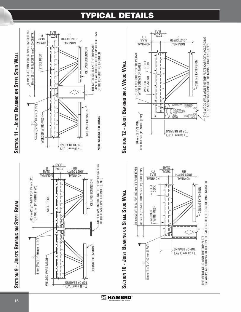
TYPICAL DETAILS
16
STEE
LDE
CK
THE
MET
AL S
TUD
AND
THE
TOP
PLAT
ECA
PACI
TY, A
CCOR
DIN
G TO
THE
SPE
CIFI
CATI
ONS
OF T
HE C
ONSU
LTIN
G EN
GIN
EER
CEIL
ING
EXTE
NSI
ON
T + 38 mm (1 1/2”)TOP OF BEARING
90 m
m (3
1 /2”
) MIN
. FOR
100
mm
(4”)
SHO
E (T
YP.)
65 m
m (2
1 /2”
) MIN
. FOR
75
mm
(3”)
SHO
E (T
YP.)
40 m
m (1
1 /2”
)5
mm
(3/16
”)W
ELDE
DW
IRE-
MES
H
NOMINALJOIST DEPTH
(D)TOTALSLAB
NOMINALSLAB
(T)
STEE
L DE
CK
THE
MET
AL S
TUD
AND
THE
TOP
PLAT
E CA
PACI
TY, A
CCOR
DIN
G TO
THE
SPE
CIFI
CATI
ONS
OF T
HE C
ONSU
LTIN
G EN
GIN
EER
CEIL
ING
EXTE
NSI
ON
T + 38 mm (1 1/2”)TOP OF BEARING
90 m
m (3
1 /2”)
MIN
. FOR
100 m
m (4
”) S
HOE
(TYP
.)65
mm
(2 1 /2
”) M
IN. F
OR 75
mm
(3”)
SHO
E (T
YP.)
40 m
m (1
1 /2”
)5
mm
(3/16
”)
WEL
DED
WIR
E-M
ESH
NO
TE: S
TAG
GER
ED J
OIS
TS
CEIL
ING
EXTE
NSI
ON
NOMINALJOIST DEPTH
(D)TOTALSLAB
NOMINALSLAB
(T)
SECT
ION
10 -
JOIS
TB
EARI
NG
ON
STEE
LST
UD
WA
LL
SECT
ION
11 -
JOIS
TSB
EARI
NG
ON
STEE
LST
UD
WA
LL
STEE
L DE
CK
STEE
L BEA
M, A
CCOR
DING
TO
THE
SPEC
IFIC
ATIO
NSOF
THE
CON
SULT
ING
ENGI
NEER
(U.N
.O)
CEIL
ING
EXTE
NSI
ON
WEL
DED
WIR
E-M
ESH
T + 38 mm (1 1/2”)TOP OF BEARING
65 m
m (2
1 /2”
) MIN
. FOR
75
mm
(3”)
OR 1
00 m
m (4
”) S
HOE
(TYP
.)40
mm
(1 1 /
2”)
5 m
m (3
/16”)
CEIL
ING
EXTE
NSI
ON
NOMINALJOIST DEPTH
(D)TOTALSLAB
NOMINALSLAB
(T)
SECT
ION
9 - J
OIS
TSB
EARI
NG
ON
STEE
LB
EAM
STEE
LDE
CK
THE
WOO
D W
ALL
AND
THE
TOP
PLAT
E CA
PACI
TY, A
CCOR
DIN
G TO
THE
SPE
CIFI
CATI
ONS
OF T
HE C
ONSU
LTIN
G EN
GIN
EER
CEIL
ING
EXTE
NSI
ON
T + 38 mm (1 1/2”)TOP OF BEARING
90 m
m (3
1 /2”
) MIN
.FO
R 10
0 m
m (4
”) S
HOE
(TYP
.)
SHOE
AN
CHOR
ED T
O TH
E PL
ANK
WIT
H SC
REW
S OR
NAI
LS
WEL
DED
WIR
E-M
ESH
NOMINALJOIST DEPTH
(D)TOTALSLAB
NOMINALSLAB
(T)
SECT
ION
12 -
JOIS
TB
EARI
NG
ON
AW
OO
DW
ALL
MEP-Technical Manual CDN 0408.qxd 08/04/2009 18:06 Page 70
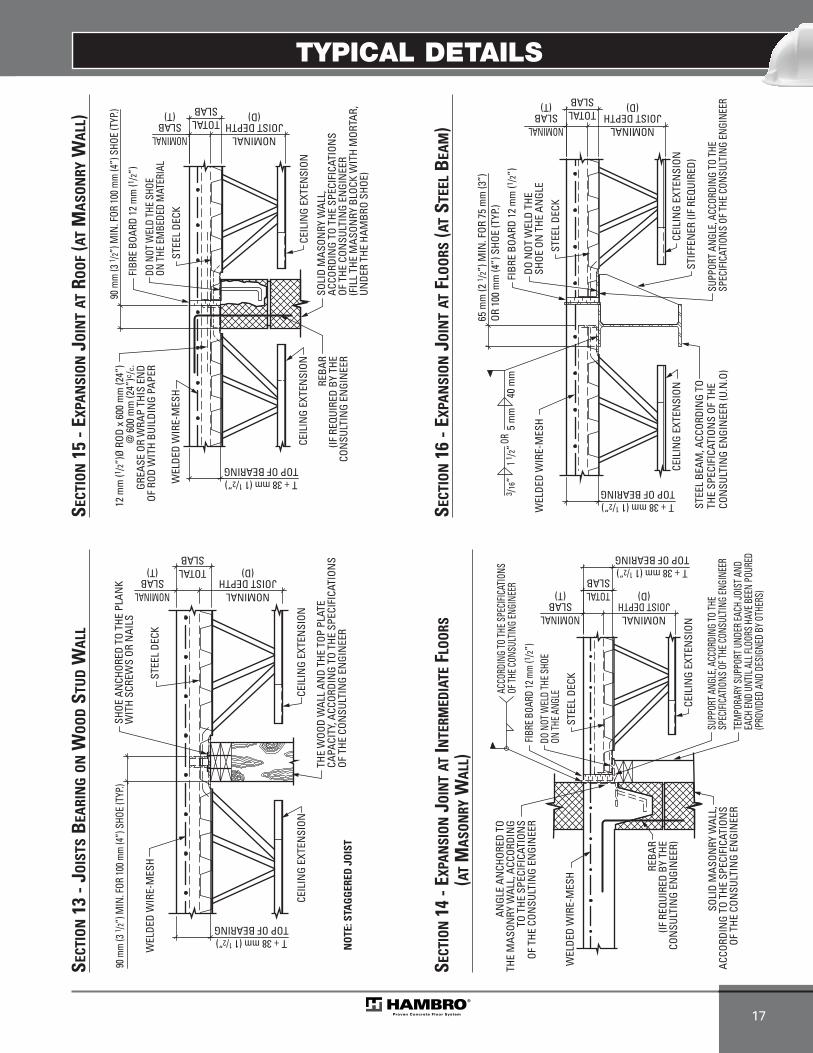
TYPICAL DETAILS
17
STEE
L DE
CK
THE
WOO
D W
ALL
AND
THE
TOP
PLAT
E CA
PACI
TY, A
CCOR
DIN
G TO
THE
SPE
CIFI
CATI
ONS
OF T
HE C
ONSU
LTIN
G EN
GIN
EER
CEIL
ING
EXTE
NSI
ON
WEL
DED
WIR
E-M
ESH
T + 38 mm (1 1/2”)TOP OF BEARING
SHOE
AN
CHOR
ED T
O TH
E PL
ANK
WIT
H SC
REW
S OR
NAI
LS
NO
TE: S
TAG
GER
ED J
OIS
T
90 m
m (3
1 /2”)
MIN
. FOR
100 m
m (4
”) S
HOE
(TYP
.)
CEIL
ING
EXTE
NSI
ON
NOMINALJOIST DEPTH
(D)TOTALSLAB
NOMINALSLAB
(T)
SECT
ION
13 -
JOIS
TSB
EARI
NG
ON
WO
OD
STU
DW
ALL
STEE
L DE
CK
SOLI
D M
ASON
RY W
ALL,
ACCO
RDIN
G TO
THE
SPE
CIFI
CATI
ONS
OF T
HE C
ONSU
LTIN
G EN
GIN
EER
WEL
DED
WIR
E-M
ESH
SUPP
ORT A
NGLE
, ACC
ORDI
NG TO
THE
SPEC
IFICA
TION
S OF
THE C
ONSU
LTIN
G EN
GINE
ER
CEIL
ING
EXTE
NSI
ON
TEM
PORA
RY S
UPPO
RT U
NDER
EACH
JOIS
T AND
EA
CH EN
D UN
TIL A
LL FL
OORS
HAV
E BEE
N PO
URED
(PRO
VIDE
D AN
D DE
SIGN
ED B
Y OTH
ERS)
T + 38 mm (1 1/2”)TOP OF BEARING
ACCO
RDIN
G TO
THE S
PECI
FICAT
IONS
OF
THE C
ONSU
LTIN
G EN
GINE
ERAN
GLE
ANCH
ORED
TO
THE
MAS
ONRY
WAL
L, A
CCOR
DIN
GTO
THE
SPE
CIFI
CATI
ONS
OF T
HE C
ONSU
LTIN
G EN
GIN
EER
FIBR
E BO
ARD
12 m
m (1
/2”)
DO N
OT W
ELD
THE S
HOE
ON TH
E ANG
LE
REBA
R(IF
REQ
UIRE
D BY
THE
CON
SULT
ING
ENGI
NEE
R)
NOMINALJOIST DEPTH
(D)TOTALSLAB
NOMINALSLAB
(T)SE
CTIO
N14
- EX
PAN
SION
JOIN
TAT
INTE
RMED
IATE
FLOO
RS(A
TM
ASON
RYW
ALL)
STEE
L DE
CK
SOLI
D M
ASON
RY W
ALL,
ACCO
RDIN
G TO
THE
SPE
CIFI
CATI
ONS
OF T
HE C
ONSU
LTIN
G EN
GIN
EER
(FIL
L TH
E M
ASON
RY B
LOCK
WIT
H M
ORTA
R,UN
DER
THE
HAM
BRO
SHOE
)
CEIL
ING
EXTE
NSI
ON
WEL
DED
WIR
E-M
ESH
T + 38 mm (1 1/2”)TOP OF BEARING
12 m
m (1
/2”)Ø
ROD
x 6
00 m
m (2
4”)
@ 6
00 m
m (2
4”)c
/c.
GREA
SE O
R W
RAP
THIS
EN
DOF
ROD
WIT
H BU
ILDI
NG
PAPE
RDO
NOT
WEL
D TH
E SH
OEON
THE
EM
BEDE
D M
ATER
IAL
REBA
R(IF
REQ
UIRE
D BY
THE
CON
SULT
ING
ENGI
NEE
R
CEIL
ING
EXTE
NSI
ON
FIBR
E BO
ARD
12 m
m (1
/2”)
90 m
m (3
1 /2”)
MIN
. FOR
100 m
m (4
”) S
HOE
(TYP
.)
NOMINALJOIST DEPTH
(D)TOTALSLAB
NOMINALSLAB
(T)
SECT
ION
15 -
EXPA
NSI
ON
JOIN
TAT
ROO
F(A
TM
ASO
NRY
WA
LL)
SUPP
ORT
ANGL
E, A
CCOR
DING
TO
THE
SPEC
IFIC
ATIO
NS O
F THE
CON
SULT
ING
ENGI
NEER
STEE
L DE
CK
STEE
L BE
AM, A
CCOR
DIN
G TO
TH
E SP
ECIF
ICAT
ION
S OF
THE
CO
NSU
LTIN
G EN
GIN
EER
(U.N
.O)
CEIL
ING
EXTE
NSI
ON
WEL
DED
WIR
E-M
ESH
T + 38 mm (1 1/2”)TOP OF BEARING
40 m
m5
mm
OR1 1
/2”3 /1
6”
DO N
OT W
ELD
THE
SHOE
ON
THE
AN
GLE
CEIL
ING
EXTE
NSI
ON
FIBR
E BO
ARD
12 m
m (1
/2”)
65 m
m (2
1 /2”
) MIN
. FOR
75
mm
(3”)
OR 1
00 m
m (4
”) S
HOE
(TYP
.)
STIF
FEN
ER (I
F RE
QUIR
ED)
NOMINALJOIST DEPTH
(D)TOTALSLAB
NOMINALSLAB
(T)
SECT
ION
16 -
EXPA
NSI
ON
JOIN
TAT
FLO
ORS
(AT
STEE
LB
EAM
)
MEP-Technical Manual CDN 0408.qxd 08/04/2009 18:06 Page 71

TYPICAL DETAILS
18
SOLI
D M
ASON
RY W
ALL
OR R
EIN
FORC
ED C
ONCR
ETE
WAL
L, A
CCOR
DIN
G TO
THE
SPE
CIFI
CATI
ONS
OF T
HE C
ONSU
LTIN
G EN
GIN
EER
WEL
DED
WIR
E-M
ESH
STEE
L DE
CK
STEE
L DE
CK A
NCH
ORED
TO T
HE W
ALL
T + 38 mm (1 1/2”)TOP OF BEARING50
mm
(2”)
MIN
.TY
P.
REBA
R(IF
REQ
UIRE
D BY
THE
CO
NSU
LTIN
G EN
GIN
EER)
NOMINALSLAB (T)
NOMINALJOIST DEPTH
(D)TOTALSLAB
SECT
ION
20 -
JOIS
TPA
RALL
ELTO
AM
ASO
NRY
WA
LLO
RCO
NCR
ETE
WA
LL
STEE
L DE
CK
CEIL
ING
EXTE
NSI
ON
WEL
DED
WIR
E-M
ESH
FIBR
E BO
ARD
12 m
m (1
/2”)
T + 38 (1 1/2”)TOP OF BEARING
40 m
m (1
1 /2”
)5
mm
(3/16
”)
12 m
m (1
/2”)Ø
ROD
x 6
00 m
m (2
4”)
@ 6
00 m
m (2
4”)c
/cGR
EASE
OR
WRA
P TH
IS E
ND
OF R
OD W
ITH
BUIL
DIN
G PA
PER
CEIL
ING
EXTE
NSI
ON
DO N
OT W
ELD
THE
SHOE
ON
THE
BEA
M
65 m
m (2
1 /2”
) MIN
. FOR
75
mm
(3”)
OR F
OR 1
00 m
m (4
”) S
HOE
(TYP
.)
STEE
L BE
AM A
CCOR
DIN
G TO
TH
E SP
ECIF
ICAT
ION
S OF
THE
CO
NSU
LTIN
G EN
GIN
EER
(UN
O)NOMINALJOIST DEPTH
(D)TOTALSLAB
NOMINALSLAB
(T)
SECT
ION
17 -
EXPA
NSI
ON
JOIN
TAT
ROO
F(A
TST
EEL
BEA
M)
SOLI
D M
ASON
RY W
ALL,
AC
CORD
ING
TO T
HE S
PECI
FICA
TION
SOF
THE
CON
SULT
ING
ENGI
NEE
R
FIBRE
BOA
RD 12
mm
(1 /2”)
WEL
DED
WIR
E-M
ESH
STEE
L DE
CK
DO N
OT W
ELD
THE
STEE
L DE
CKON
THE
EM
BEDE
D M
ATER
IAL
T + 38 mm (1 1/2”)TOP OF BEARING
75 m
m (3
”) M
IN.
TYP.
REBA
R(IF
REQ
UIRE
D BY
THE
CON
SULT
ING
ENGI
NEE
R)
NOMINALSLAB (T)
NOMINALJOIST DEPTH
(D)TOTALSLAB
SECT
ION
19 -
JOIS
TPA
RALL
ELTO
EXPA
NSI
ON
JOIN
T
STEE
L DE
CK
DIAM
ETER
� 20
0 mm
(8”)
** R
EBAR
ARO
UND
THE
HO
LE IS
NOT
REQ
UIRE
D**
THE
QUA
NTIT
Y OF H
OLE
AT
150 m
m (6”
) & M
ORE
OF
THE J
OIST
IS
NO
T IM
PORT
ANT
END
OFSL
AB
NOMINALSLAB
(T)OP
ENIN
GSE
E TY
PICA
LRE
INFO
RCEM
ENT
FOR
SLAB
OPE
NIN
G.
NOMINALJOIST DEPTH
(D)
WEL
DED
WIR
E-M
ESH
TEM
PORA
RY
SUPP
ORT
(DES
IGNE
D &
SUPP
LIED
BY O
THER
S)150 m
m (6”
)MI
N.15
0 mm
(6”)
MIN.
150 m
m (6”
)MI
N.
20 mm (3/4”) MIN.APPLICABLE
IN EACH CASE
20 mm (3/4”) MIN.APPLICABLE
IN EACH CASE
TOTALSLAB
HOLE
HO
LE
HOLE
SECT
ION
18 -
MIN
IMU
MCL
EARA
NCE
FOR
OPE
NIN
GA
ND
HO
LEIN
THE
SLA
B
MEP-Technical Manual CDN 0408.qxd 08/04/2009 18:06 Page 72
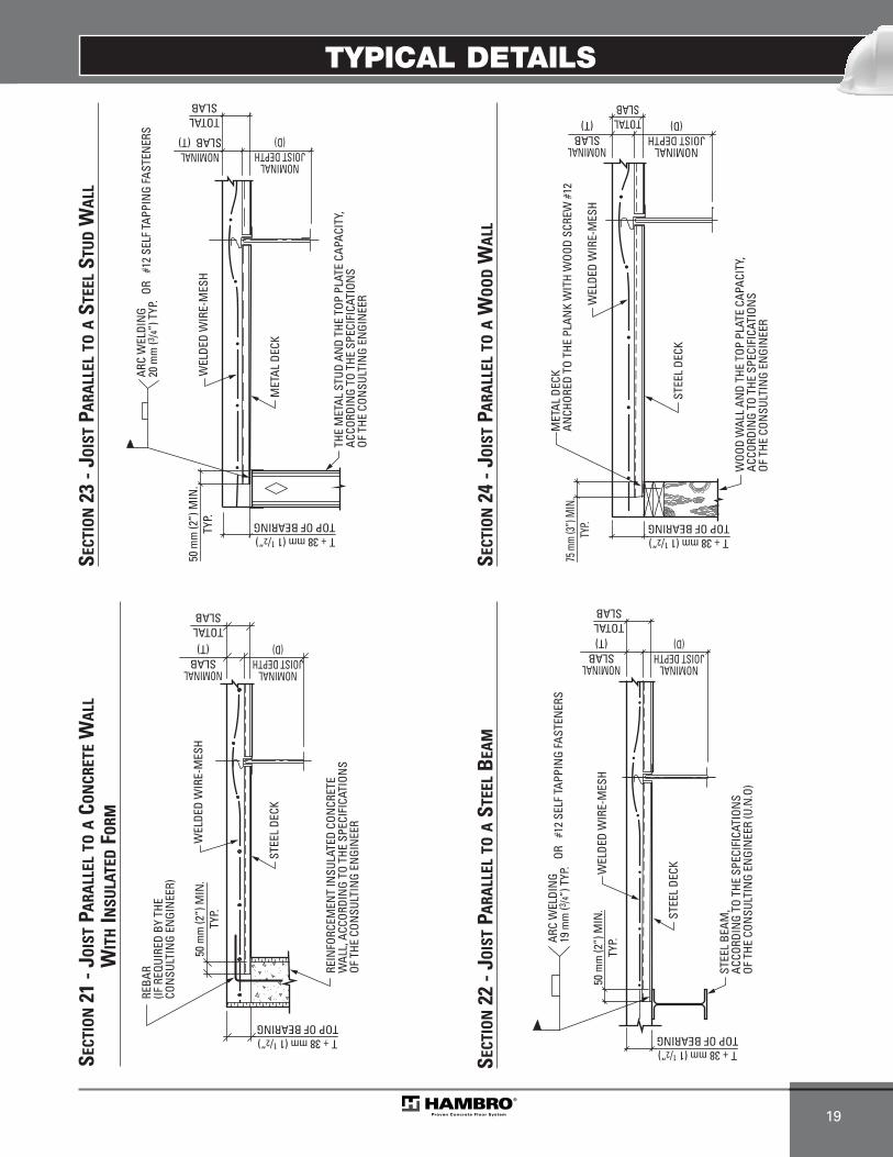
TYPICAL DETAILS
19
REIN
FORC
EMEN
T IN
SULA
TED
CON
CRET
E W
ALL,
ACC
ORDI
NG
TO T
HE S
PECI
FICA
TION
SOF
THE
CON
SULT
ING
ENGI
NEE
R
STEE
L DE
CK
WEL
DED
WIR
E-M
ESH
50 m
m (2
”) M
IN.
TYP.
T + 38 mm (1 1/2”)TOP OF BEARING
REBA
R(IF
REQ
UIRE
D BY
THE
CON
SULT
ING
ENGI
NEE
R)
NOMINALSLAB
(T)
NOMINALJOIST DEPTH
(D)TOTALSLAB
SECT
ION
21 -
JOIS
TPA
RALL
ELTO
ACO
NCR
ETE
WA
LLW
ITH
INSU
LATE
DFO
RM
STEE
L BE
AM,
ACCO
RDIN
G TO
THE
SPE
CIFI
CATI
ONS
OF T
HE C
ONSU
LTIN
G EN
GIN
EER
(U.N
.O)
ARC
WEL
DIN
G19
mm
(3/4”
) TYP
. WEL
DED
WIR
E-M
ESH
STEE
L DE
CK
T + 38 mm (1 1/2”)TOP OF BEARING
50 m
m (2
”) M
IN.
TYP.
OR
#12
SELF
TAP
PIN
G FA
STEN
ERS
NOMINALSLAB
(T)
NOMINALJOIST DEPTH
(D)TOTALSLAB
SECT
ION
22 -
JOIS
TPA
RALL
ELTO
AST
EEL
BEA
M
ARC
WEL
DIN
G20
mm
(3/4”
) TYP
.
MET
AL D
ECK
WEL
DED
WIR
E-M
ESH
THE
MET
AL S
TUD
AND
THE
TOP
PLAT
E CA
PACI
TY,
ACCO
RDIN
G TO
THE
SPE
CIFI
CATI
ONS
OF T
HE C
ONSU
LTIN
G EN
GIN
EER
50 m
m (2
”) M
IN.
TYP.
T + 38 mm (1 1/2”)TOP OF BEARING
OR
#12
SELF
TAP
PIN
G FA
STEN
ERS
NOMINALSLAB (T)
NOMINALJOIST DEPTH
(D)
TOTALSLAB
SECT
ION
23 -
JOIS
TPA
RALL
ELTO
AST
EEL
STU
DW
ALL
STEE
L DE
CK
WEL
DED
WIR
E-M
ESH
WOO
D W
ALL
AND
THE
TOP
PLAT
E CA
PACI
TY,
ACCO
RDIN
G TO
THE
SPE
CIFI
CATI
ONS
OF T
HE C
ONSU
LTIN
G EN
GIN
EER
MET
AL D
ECK
ANCH
ORED
TO
THE
PLAN
K W
ITH
WOO
D SC
REW
#12
T + 38 mm (1 1/2”)TOP OF BEARING
75 m
m (3”
) MIN
.TY
P.
NOMINALSLAB
(T)
NOMINALJOIST DEPTH
(D)TOTALSLAB
SECT
ION
24 -
JOIS
TPA
RALL
ELTO
AW
OO
DW
ALL
MEP-Technical Manual CDN 0408.qxd 08/04/2009 18:06 Page 73
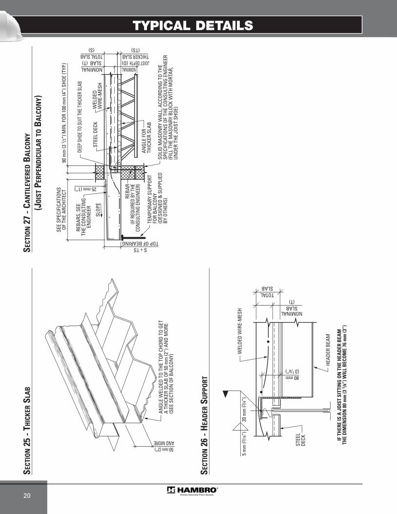
TYPICAL DETAILS
20
ANGL
E W
ELDE
D TO
THE
TOP
CHO
RD T
O GE
T A
THIC
KER
SLAB
OF
50 m
m (2
”) A
ND
MOR
E(S
EE S
ECTI
ON O
F BA
LCON
Y)
50 mm (2”)AND MORE
SECT
ION
25 -
THIC
KER
SLA
B
ANGL
E FO
RTH
ICKE
R SL
AB
WEL
DED
WIR
E-M
ESH
STEE
L DE
CK
SEE
SPEC
IFIC
ATIO
NS
OF T
HE A
RCHI
TECT
REBA
RS, S
EE
THE
CON
SULT
ING
ENGI
NEE
R
SLOP
E
TEM
PORA
RY S
UPPO
RTFO
R BA
LCON
Y(D
ESIG
NED
& S
UPPL
IED
BY O
THER
S)SO
LID
MAS
ONRY
WAL
L, A
CCOR
DIN
G TO
THE
SPEC
IFIC
ATIO
NS
OF T
HE C
ONSU
LTIN
G EN
GIN
EER
(FIL
L TH
E M
ASON
RY B
LOCK
WIT
H M
ORTA
R,
UNDE
R TH
E JO
IST
SHOE
)
90 m
m (3
1 /2”
) MIN
. FOR
100
mm
(4”)
SHO
E (T
YP.)
THICKER SLAB(TS)
DEEP
SHO
E TO
SUIT
THE T
HICK
ER S
LAB
REBA
R(IF
REQ
UIRE
D BY
THE
CONS
ULTI
NG E
NGIN
EER)25 mm (1”)
S + TSTOP OF BEARING
NOMINALSLAB (T)
NOMINALJOIST DEPTH (D)
TOTAL SLAB(S)
SECT
ION
27 -
CAN
TILE
VERE
DB
ALC
ON
Y
(JO
IST
PERP
END
ICU
LAR
TOB
ALC
ON
Y)
HEAD
ER B
EAM
WEL
DED
WIR
E-M
ESH
STEE
LDE
CK
80 mm(3 1/8”)
20 m
m (3
/4”)
5 m
m (3
/16”)
TOTALSLAB
IF T
HER
E IS
A J
OIS
T SI
TTIN
G O
N T
HE
HEA
DER
BEA
MTH
E D
IMEN
SIO
N 8
0 m
m (3
1 /8”
) WIL
L B
ECO
ME
76 m
m (3
”)
NOMINALSLAB
(T)SE
CTIO
N26
- H
EAD
ERSU
PPO
RT
MEP-Technical Manual CDN 0408.qxd 08/04/2009 18:06 Page 74

TYPICAL DETAILS
21
IMPO
RTA
NT;
BRI
DG
ING
AN
GLE
S TO
BE
INST
ALL
ED A
FTER
FO
RMS
STRI
PPED
BU
TB
EFO
RE T
HE
REM
OVA
L O
F B
ALC
ON
Y TE
MPO
RARY
SU
PPO
RTS
SEE
SPEC
IFIC
ATIO
NS
OF T
HE A
RCHI
TECT
SLOP
EW
ELDE
DW
IRE-
MES
H
SEE
PLAN
SEE
PLAN
50 m
m (2
”) M
IN.
TYP.
REBA
R(IF
REQ
UIRE
D BY
THE
CON
SULT
ING
ENGI
NEE
R)25 mm (1”)
STEE
L DE
CK
ANGL
E FO
RTH
ICKE
R SL
AB
S + TSTOP OF BEARING
NOMINALSLAB (T)
NOMINALJOIST
DEPTH (D)
THICKER SLAB(TS)
TOTAL SLAB (S)
REBA
R,RE
BAR,
ACCO
RDIN
G TO
THE
ACCO
RDIN
G TO
THE
SPEC
IFICA
TION
S OF
THE
SPEC
IFICA
TION
S OF
THE
CONS
ULTI
NG EN
GINE
ERCO
NSUL
TING
ENGI
NEER
REBA
R,AC
CORD
ING
TO TH
ESP
ECIFI
CATI
ONS
OF TH
ECO
NSUL
TING
ENGI
NEER
BRID
GIN
G TO
BOT
TOM
CHO
RD M
AY
BE N
ECES
SARY
IF U
PLIF
T DU
E TO
CA
NTI
LEVE
R BA
LCON
Y EX
CEED
S GR
AVIT
Y LO
AD. (
IF R
EQUI
RED
BYTH
E EN
GIN
EER)
TEM
PORA
RY
SUPP
ORT
FOR
BALC
ONY
(DES
IGNE
D &
SUPP
LIED
BY O
THER
S)
SOLI
D M
ASON
RY W
ALL,
ACC
ORDI
NG
TO T
HE S
PECI
FICA
TION
S OF
THE
CO
NSU
LTIN
G EN
GIN
EER
BRID
GIN
G TO
BOT
TOM
CHO
RD M
AY
BE N
ECES
SARY
IF U
PLIF
T DU
E TO
CA
NTI
LEVE
R BA
LCON
Y EX
CEED
S GR
AVIT
Y LO
AD. (
IF R
EQUI
RED
BYTH
E EN
GIN
EER)
IMPO
RTA
NT;
BRI
DG
ING
AN
GLE
S TO
BE
INST
ALL
ED A
FTER
FO
RMS
STRI
PPED
BU
TB
EFO
RE T
HE
REM
OVA
L O
F B
ALC
ON
Y TE
MPO
RARY
SU
PPO
RTS
SEE
SPEC
IFIC
ATIO
NS
OF T
HE A
RCHI
TECT
SLOP
EW
ELDE
DW
IRE-
MES
H
SOLI
D M
ASON
RY W
ALL,
ACCO
RDIN
G TO
THE
SP
ECIF
ICAT
ION
S OF
THE
CO
NSU
LTIN
G EN
GIN
EER
STEE
L DE
CKTE
MPO
RARY
SU
PPOR
TFO
R BA
LCON
Y(D
ESIG
NED
& SU
PPLIE
D BY
OTH
ERS)
SEE
PLAN
SEE
PLAN
50 m
m (2
”) M
IN.
TYP.
REBA
R(IF
REQ
UIRE
D BY
THE
CON
SULT
ING
ENGI
NEE
R)
25 mm (1”)
S + TSTOP OF BEARING
THICKER SLAB(TS)
REBA
R,RE
BAR,
ACCO
RDIN
G TO
THE
ACCO
RDIN
G TO
THE
SPEC
IFICA
TION
S OF
THE
SPEC
IFICA
TION
S OF
THE
CONS
ULTI
NG EN
GINE
ERCO
NSUL
TING
ENGI
NEER
REBA
R,AC
CORD
ING
TO TH
ESP
ECIFI
CATI
ONS
OF TH
ECO
NSUL
TING
ENGI
NEER
NOMINALSLAB (T)
NOMINALJOIST
DEPTH (D)
TOTAL SLAB (S)
SECT
ION
29 -
CAN
TILE
VERE
DB
ALC
ON
Y(J
OIS
TPA
RALL
ELTO
BA
LCO
NY)
SECT
ION
28 -
CAN
TILE
VERE
DB
ALC
ON
Y(S
HA
LLO
WJO
IST
PARA
LLEL
TOB
ALC
ON
Y)
MEP-Technical Manual CDN 0408.qxd 08/04/2009 18:06 Page 75
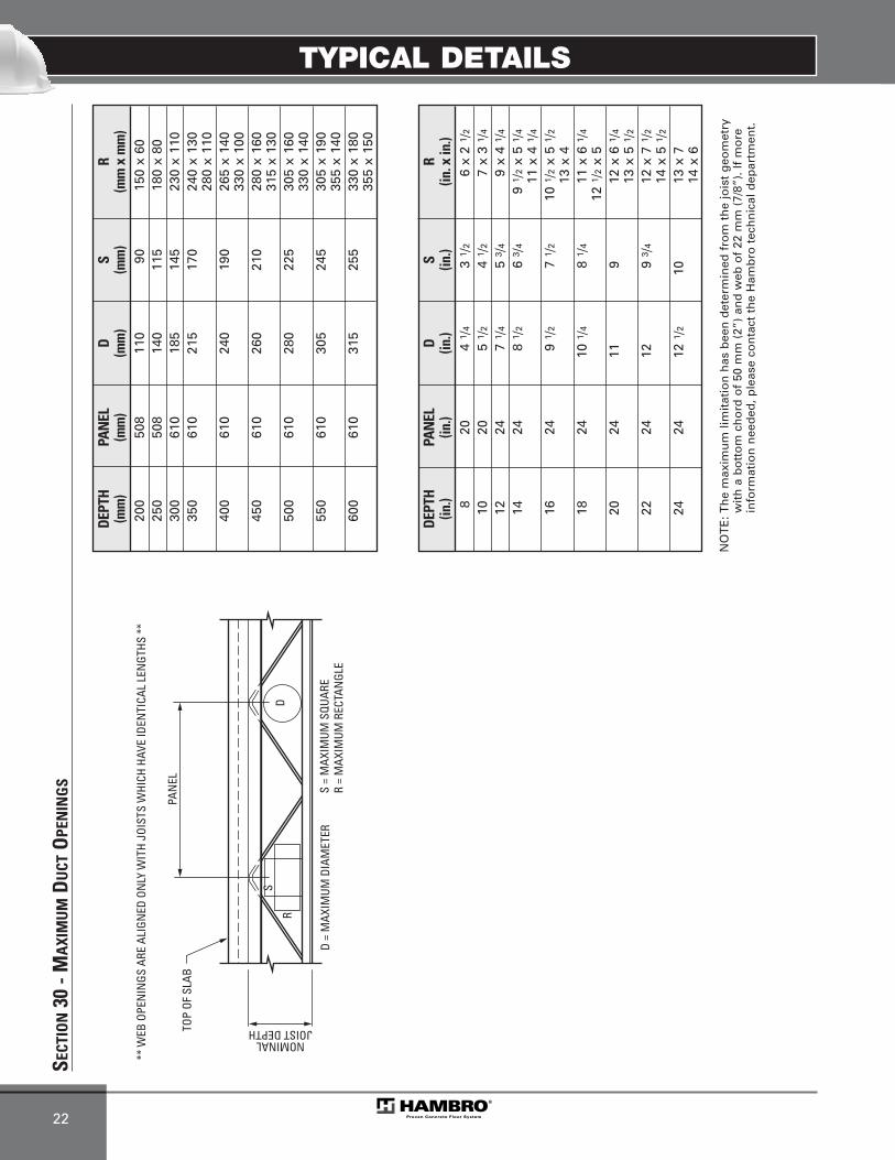
TYPICAL DETAILS
22
SECT
ION
30 -
MA
XIM
UM
DU
CTO
PEN
ING
S
D
D =
MAX
IMUM
DIA
MET
ER
R
S =
MAX
IMUM
SQU
ARE
R =
MAX
IMUM
REC
TAN
GLE
PAN
ELTO
P OF
SLA
B
NOMINALJOIST DEPTH
** W
EB O
PEN
INGS
ARE
ALI
GNED
ON
LY W
ITH
JOIS
TS W
HICH
HAV
E ID
ENTI
CAL
LEN
GTHS
**
SS
DEPT
HPA
NEL
D
S R
(in.)
(in.)
(in.)
(in.)
(in. x
in.)
820
4 1 /
43
1 /2
6 x
2 1 /
2
1020
5 1 /
24
1 /2
7 x
3 1 /
4
1224
7 1 /
45
3 /4
9 x
4 1 /
4
1424
8 1 /
26
3 /4
9 1 /
2x
5 1 /
4
11 x
4 1
/416
249
1 /2
7 1 /
210
1/2
x 5
1 /2
13 x
418
2410
1/4
8 1 /
411
x 6
1/4
12 1
/2x
520
2411
912
x 6
1/4
13 x
5 1
/222
2412
9 3 /
412
x 7
1/2
14 x
5 1
/224
2412
1/2
1013
x 7
14 x
6
DEPT
HPA
NEL
D
S R
(mm
)(m
m)
(mm
)(m
m)
(mm
x m
m)
200
508
110
9015
0 x
6025
050
814
011
518
0 x
8030
061
018
514
523
0 x
110
350
610
215
170
240
x 13
028
0 x
110
400
610
240
190
265
x 14
033
0 x
100
450
610
260
210
280
x 16
031
5 x
130
500
610
280
225
305
x 16
033
0 x
140
550
610
305
245
305
x 19
035
5 x
140
600
610
315
255
330
x 18
035
5 x
150
NO
TE
: Th
e m
axim
um
lim
itat
ion
has
bee
n d
eter
min
ed f
rom
th
e jo
ist
geo
met
ryw
ith
a b
ott
om
ch
ord
of
50 m
m (
2”)
and
web
of
22 m
m (
7/8”
). If
mo
rein
form
atio
n n
eed
ed, p
leas
e co
nta
ct t
he
Ham
bro
tec
hn
ical
dep
artm
ent.
MEP-Technical Manual CDN 0408.qxd 08/04/2009 18:06 Page 76

TYPICAL DETAILS
23
8.3 DTC (LH SERIES)SECTION NO. DESCRIPTION PAGE
1 Standard Shoe
2 Bolted Joists at Steel Beam
3 Bolted Joist at Column (Flange / Web).................................................. 24
4 Joist Bearing on Steel Beam
5 Minimum Clearance for Openings and Holes in the Slab
6 Joist Parallel to a Steel Beam
7 Thicker Slab.................................................. 25
8 Flange Hanger for Steel Beam and Wall
9 Flange Hanger for Insulated Concrete Form
10 Maximum LH Duct Openings .............................................. 26
11 Joist Parallel to a Concrete Wall With Insulated Form
12 Joist Bearing on Concrete Wall With Insulated Form .............................................. 27
}}}
}
MEP-Technical Manual CDN 0408.qxd 08/04/2009 18:06 Page 77
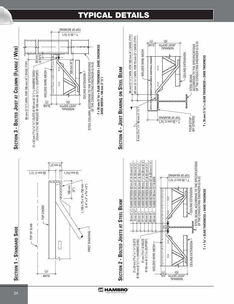
TYPICAL DETAILS
24
CEIL
ING
EXTE
NSI
ON
- T +
35
mm
(1 3 /8
) = S
LAB
TH
ICKN
ESS
+ SH
OE
THIC
KNES
S- S
HO
E W
IDTH
= 1
90 m
m (7
1 /2”
)
TOP OF BEARING
STEE
L CO
LUM
N, A
CCOR
DIN
G TO
THE
SPE
CIFI
CATI
ONS
OF T
HE C
ONSU
LTIN
G EN
GIN
EER
(U.N
.O)
WEL
DED
WIR
E-M
ESH
21 x
32 m
m (13
/16”x
1 1 /4”)
SLO
TS @
165 m
m (6
1 /2”)
c /c (H
AMBR
O SH
OE)
21m
m (1
3 /16”
)Ø H
OLE
S @
165
mm
(6 1 /
2”) c /c
(SU
PPO
RT)
SLAB(T)
T + 35 (1 3/8”)
NOMINALJOIST DEPTH
(D)
100
mm
(4”)
90 m
m (3
1 /2”
) MIN
. FOR
100
mm
(4”)
SHO
E (T
YP.) (2
(2
1 /2”
)65
mm
65 m
m(2
1 /2”
)65
mm
TOP
CHOR
D
TOP
OF S
LAB
(T)SLAB
100
mm
(L 4
” x
3” x
3 /8”
x 6
”)L
100
x 75
x 1
0 x
150
mm
75 mm (3”)
(4”)
FIRS
T DI
AGON
AL
39 mm (1 1/2”) 10 mm (3/8”)
T +
35 m
m (1
3 /8”
) = S
LAB
TH
ICKN
ESS
+ SH
OE
THIC
KNES
S
TOP OF BEARING
STEE
L BE
AM,
ACCO
RDIN
G TO
THE
SPE
CIFI
CATI
ONS
OF T
HE C
ONSU
LTIN
G EN
GIN
EER
(U.N
.O)
WEL
DED
WIR
E-M
ESH
CEIL
ING
EXTE
NSI
ON
90 m
m (3
1 /2”
) MIN
. FOR
100
mm
(4”)
SHO
E (T
YP.)
65 m
m (2
1 /2”
) MIN
. FOR
75
mm
(3”)
SHO
E (T
YP.)
SLAB(T)
T + 35 mm (1 3/8”)
NOMINALJOIST DEPTH
(D)
5 m
m (3
/16”)
40 m
m (1
1 /2”
)
POUR
STO
P(B
Y OT
HERS
)
SECT
ION
3 - B
OLT
EDJO
IST
ATCO
LUM
N(F
LAN
GE
/ WEB
)SE
CTIO
N1
- STA
ND
ARD
SHO
E
SECT
ION
4 - J
OIS
TB
EARI
NG
ON
STEE
LB
EAM
CEIL
ING
EXTE
NSI
ON
T +
1 3 /8
” =
SLA
B T
HIC
KNES
S +
SHO
E TH
ICKN
ESS
TOP OF BEARING
STEE
L BE
AM, A
CCOR
DIN
G TO
THE
SPE
CIFI
CATI
ONS
OF T
HE C
ONSU
LTIN
G EN
GIN
EER
(U.N
.O)
WEL
DED
WIR
E-M
ESH
21 x
32 m
m (13
/16” x
1 1 /4
”) SL
OTS
@ 16
5 mm
(6 1 /2
”) c /c
(HAM
BRO
SHOE
)
21 m
m (13
/16”)
Ø HO
LES
@ 16
5 mm
(6 1 /2
”) c /c
(SUP
PORT
)
CEIL
ING
EXTE
NSI
ON
FLAN
GE B
ETW
EEN
102 m
m (4”
) & 12
5 mm
(4 7 /8”
)58
mm
(2 1 /4”
) FLAN
GE B
ETW
EEN
127 m
m (5”
) & 15
0 mm
(5 7 /8”
)70
mm
(2 3 /4”
) FLAN
GE B
ETW
EEN
152 m
m (6”
) & 18
8 mm
(7 3 /8”
)10
2 mm
(4”)
FLAN
GE B
ETW
EEN
190 m
m (7
1 /2”) &
228 m
m (8
7 /8”)
127 m
m (5”
)FL
ANGE
BET
WEE
N 23
0 mm
(9”) &
252 m
m (9
7 /8”)
152 m
m (6”
)FL
ANGE
BET
WEE
N 25
4 mm
(10”)
& 30
3 mm
(11 7 /8”
)20
3 mm
(8”)
FLAN
GE O
F 305
mm
(12”)
& M
ORE
230 m
m (9”
)
SLAB(T)
T + 35 mm (1 3/8”)
NOMINALJOIST DEPTH
(D)
SECT
ION
2 - B
OLT
EDJO
ISTS
ATST
EEL
BEA
M
MEP-Technical Manual CDN 0408.qxd 08/04/2009 18:06 Page 78
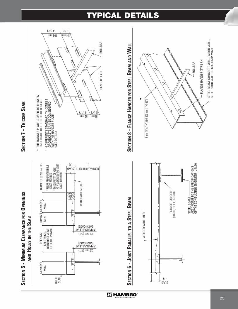
TYPICAL DETAILS
25
WEL
DED
WIR
E-M
ESH ST
EEL
BEAM
,AC
CORD
ING
TO T
HE S
PECI
FICA
TION
SOF
THE
CON
SULT
ING
ENGI
NEE
R (U
.N.O
)
FLAN
GE H
ANGE
R(F
IXED
, SEE
ED-
D500
)
SLAB(T)
* TH
E HA
NGE
R PL
ATE
IS U
SED
TO T
HICK
EN
UNDE
R SI
DE O
F TH
E CO
NCR
ETE
SLAB
.
* 4
DIF
FERE
NTS
STA
NDA
RD T
HICK
NES
S
OF C
ONCR
ETE
CAN
BE
CON
SIDE
RED
W
ITH
THE
HAN
GER
PLAT
E
(SEE
DET
AIL)
158 mm (6 1/4”)
82 mm (3 1/4”)
108 mm(4 1/4”)
184 mm(7 1/4”)
HAN
GER
PLAT
ERO
LLBA
R
SECT
ION
6 - J
OIS
TPA
RALL
ELTO
AST
EEL
BEA
M
SECT
ION
7 - T
HIC
KER
SLA
B
FLAN
GE H
ANGE
R (T
YPE
F.H)
ROLL
BAR
STEE
L BE
AM, C
ONCR
ETE
WAL
L, W
OOD
WAL
L,ST
EEL
STUD
WAL
L OR
MAS
ONRY
WAL
L
25 @
300 m
m (1”
@ 12
”)5 m
m (3 /
16”)
SECT
ION
8 - F
LAN
GE
HA
NG
ERFO
RST
EEL
BEA
MA
ND
WA
LL
WEL
DED
WIR
E-M
ESH
DIAM
ETER
� 20
0 mm
(8”)
** RE
BAR A
ROUN
D THE
HOLE
IS N
OT RE
QUIRE
D**
THE Q
UANT
ITY OF
HOLE
AT 7”
& M
ORE O
F THE
JOIST
IS NO
T IMP
ORTA
NT
SLAB(T)
OPEN
ING
SEE
TYPI
CAL
REIN
FORC
EMEN
TFO
R SL
AB O
PENI
NG.
NOMINAL JOIST DEPTH(D)
END
OFSL
AB
178 m
m (7”
)M
IN.
178 m
m (7”
)M
IN.
178 m
m (7”
)M
IN.
20 mm (3/4”)(APPLICABLE AT
EACH CASE)
20 mm (3/4”)(APPLICABLE AT
EACH CASE)
HOLE
HO
LE
HOLE
SECT
ION
5 - M
INIM
UM
CLEA
RAN
CEFO
RO
PEN
ING
SA
ND
HO
LES
INTH
ESL
AB
MEP-Technical Manual CDN 0408.qxd 08/04/2009 18:06 Page 79
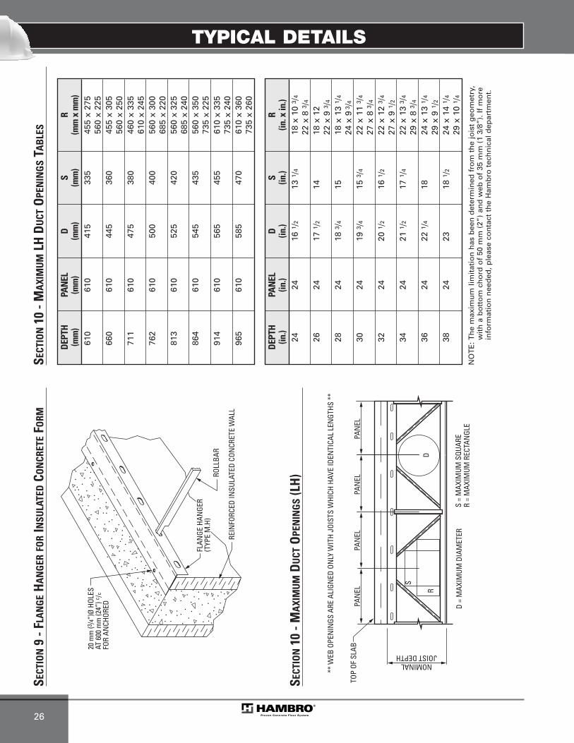
TYPICAL DETAILS
26
FLAN
GE H
ANGE
R(T
YPE
M.H
)RO
LLBA
R
20 m
m (3
/4”)Ø
HOL
ESAT
600
mm
(24”
) c/c
FOR
ANCH
ORED
REIN
FORC
ED IN
SULA
TED
CON
CRET
E W
ALL
SECT
ION
9 - F
LAN
GE
HA
NG
ERFO
RIN
SULA
TED
CON
CRET
EFO
RM
D
S
D =
MAX
IMUM
DIA
MET
ER
R
S =
MAX
IMUM
SQU
ARE
R =
MAX
IMUM
REC
TAN
GLE
TOP
OF S
LAB
JOIST DEPTHNOMINAL
PAN
ELPA
NEL
PAN
ELPA
NEL
** W
EB O
PEN
INGS
ARE
ALI
GNED
ON
LY W
ITH
JOIS
TS W
HICH
HAV
E ID
ENTI
CAL
LEN
GTHS
**
SECT
ION
10 -
MA
XIM
UM
DU
CTO
PEN
ING
S(L
H)
SECT
ION
10 -
MA
XIM
UM
LH D
UCT
OPE
NIN
GS
TAB
LES
DEPT
HPA
NEL
D
S R
(in.)
(in.)
(in.)
(in.)
(in. x
in.)
2424
16 1
/213
1/4
18 x
10
3 /4
22 x
8 3
/426
2417
1/2
1418
x 1
222
x 9
3/4
2824
18 3
/415
18 x
13
1 /4
24 x
93 /
4
3024
19 3
/415
3/4
22 x
11
3 /4
27 x
8 3
/432
2420
1/2
16 1
/222
x 1
2 3 /
4
27 x
9 1
/234
2421
1/2
17 1
/422
x 1
3 3 /
4
29 x
8 3
/436
2422
1/4
1824
x 1
3 1 /
4
29 x
9 1
/238
2423
18 1
/224
x 1
4 1 /
4
29 x
10
1 /4
DEPT
HPA
NEL
D
S R
(mm
)(m
m)
(mm
)(m
m)
(mm
x m
m)
610
610
415
335
455
x 27
556
0 x
225
660
610
445
360
455
x 30
556
0 x
250
711
610
475
380
460
x 33
561
0 x
245
762
610
500
400
560
x 30
068
5 x
220
813
610
525
420
560
x 32
568
5 x
240
864
610
545
435
560
x 35
073
5 x
225
914
610
565
455
610
x 33
573
5 x
240
965
610
585
470
610
x 36
073
5 x
260
NO
TE
: Th
e m
axim
um
lim
itat
ion
has
bee
n d
eter
min
ed f
rom
th
e jo
ist
geo
met
ry,
wit
h a
bo
tto
m c
ho
rd o
f 50
mm
(2”
) an
d w
eb o
f 35
mm
(1
3/8”
). If
mo
rein
form
atio
n n
eed
ed, p
leas
e co
nta
ct t
he
Ham
bro
tec
hn
ical
dep
artm
ent.
MEP-Technical Manual CDN 0408.qxd 08/04/2009 18:06 Page 80
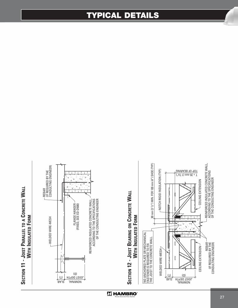
TYPICAL DETAILS
27
FLAN
GE H
ANGE
R(F
IXED
, SEE
ED-
D500
)
REIN
FORC
ED IN
SULA
TED
CON
CRET
E W
ALL,
ACCO
RDIN
G TO
THE
SPE
CIFI
CATI
ONS
OF T
HE C
ONSU
LTIN
G EN
GIN
EER
WEL
DED
WIR
E-M
ESH
REBA
R(IF
REQ
UIRE
D BY
THE
CO
NSU
LTIN
G EN
GIN
EER)
(T)SLAB
JOIST DEPTHNOMINAL
(D)
SECT
ION
11 -
JOIS
TPA
RALL
ELTO
ACO
NCR
ETE
WA
LLW
ITH
INSU
LATE
DFO
RM
CEIL
ING
EXTE
NSI
ON
TOP OF BEARING
REIN
FORC
ED IN
SULA
TED
CON
CRET
E W
ALL,
ACCO
RDIN
G TO
THE
SPE
CIFI
CATI
ONS
OF T
HE C
ONSU
LTIN
G EN
GIN
EER
WEL
DED
WIR
E-M
ESH
CEIL
ING
EXTE
NSI
ON
90 m
m (3
1 /2”)
MIN
. FOR
100 m
m (4
”) S
HOE
(TYP
.)
SLAB(T)
T + 35 mm (1 3/8”)
NOMINALJOIST DEPTH
(D)
REBA
R(IF
REQ
UIRE
D BY
THE
CON
SULT
ING
ENGI
NEE
R)
NO
ANCH
ORED
PLA
TE O
R M
ECHA
NIC
ALFA
STEN
ER IS
REQ
UIRE
D TO
FIX
TH
E JO
IST
TO T
HE C
ONCR
ETE
WAL
L.
NOT
CH R
IGID
INSU
LATI
ON (T
YP.)
SECT
ION
12 -
JOIS
TB
EARI
NG
ON
CON
CRET
EW
ALL
WIT
HIN
SULA
TED
FORM
MEP-Technical Manual CDN 0408.qxd 08/04/2009 18:06 Page 81

28
MEP-Technical Manual CDN 0408.qxd 08/04/2009 18:06 Page 82
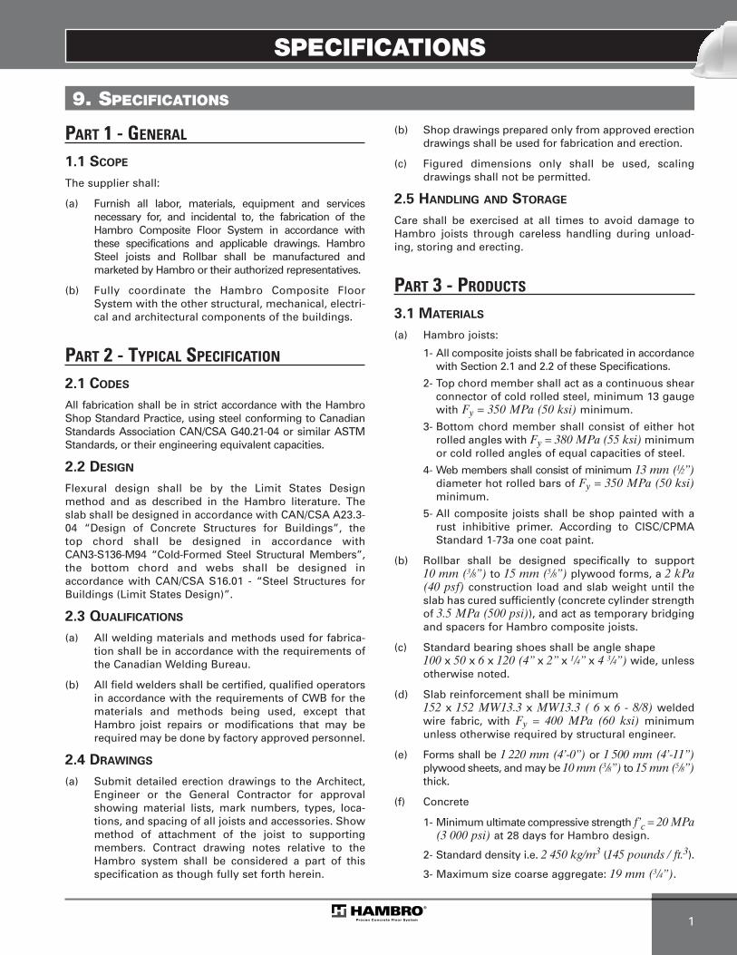
SPECIFICATIONS
1
9. SPECIFICATIONS
PART 1 - GENERAL
1.1 SCOPE
The supplier shall:
(a) Furnish all labor, materials, equipment and services necessary for, and incidental to, the fabrication of theHambro Composite Floor System in accordance with these specifications and applicable drawings. HambroSteel joists and Rollbar shall be manufactured and marketed by Hambro or their authorized representatives.
(b) Fully coordinate the Hambro Composite FloorSystem with the other structural, mechanical, electri-cal and architectural components of the buildings.
PART 2 - TYPICAL SPECIFICATION
2.1 CODES
All fabrication shall be in strict accordance with the HambroShop Standard Practice, using steel conforming to CanadianStandards Association CAN/CSA G40.21-04 or similar ASTMStandards, or their engineering equivalent capacities.
2.2 DESIGN
Flexural design shall be by the Limit States Designmethod and as described in the Hambro literature. Theslab shall be designed in accordance with CAN/CSA A23.3-04 “Design of Concrete Structures for Buildings”, thetop chord shall be designed in accordance withCAN3-S136-M94 “Cold-Formed Steel Structural Members”,the bottom chord and webs shall be designed inaccordance with CAN/CSA S16.01 - “Steel Structures forBuildings (Limit States Design)”.
2.3 QUALIFICATIONS
(a) All welding materials and methods used for fabrica-tion shall be in accordance with the requirements ofthe Canadian Welding Bureau.
(b) All field welders shall be certified, qualified operators in accordance with the requirements of CWB for thematerials and methods being used, except thatHambro joist repairs or modifications that may berequired may be done by factory approved personnel.
2.4 DRAWINGS
(a) Submit detailed erection drawings to the Architect,Engineer or the General Contractor for approvalshowing material lists, mark numbers, types, loca-tions, and spacing of all joists and accessories. Showmethod of attachment of the joist to supportingmembers. Contract drawing notes relative to theHambro system shall be considered a part of thisspecification as though fully set forth herein.
(b) Shop drawings prepared only from approved erectiondrawings shall be used for fabrication and erection.
(c) Figured dimensions only shall be used, scalingdrawings shall not be permitted.
2.5 HANDLING AND STORAGE
Care shall be exercised at all times to avoid damage toHambro joists through careless handling during unload-ing, storing and erecting.
PART 3 - PRODUCTS
3.1 MATERIALS
(a) Hambro joists:
1- All composite joists shall be fabricated in accordancewith Section 2.1 and 2.2 of these Specifications.
2- Top chord member shall act as a continuous shearconnector of cold rolled steel, minimum 13 gaugewith Fy = 350 MPa (50 ksi) minimum.
3- Bottom chord member shall consist of either hot rolled angles with Fy = 380 MPa (55 ksi) minimumor cold rolled angles of equal capacities of steel.
4- Web members shall consist of minimum 13 mm (1/2”)diameter hot rolled bars of Fy = 350 MPa (50 ksi)minimum.
5- All composite joists shall be shop painted with arust inhibitive primer. According to CISC/CPMAStandard 1-73a one coat paint.
(b) Rollbar shall be designed specifically to support 10 mm (3/8”) to 15 mm (5/8”) plywood forms, a 2 kPa (40 psf) construction load and slab weight until theslab has cured sufficiently (concrete cylinder strengthof 3.5 MPa (500 psi)), and act as temporary bridgingand spacers for Hambro composite joists.
(c) Standard bearing shoes shall be angle shape 100 x 50 x 6 x 120 (4” x 2” x 1/4” x 4 3/4”) wide, unlessotherwise noted.
(d) Slab reinforcement shall be minimum 152 x 152 MW13.3 x MW13.3 ( 6 x 6 - 8/8) weldedwire fabric, with Fy = 400 MPa (60 ksi) minimumunless otherwise required by structural engineer.
(e) Forms shall be 1 220 mm (4’-0”) or 1 500 mm (4’-11”)plywood sheets, and may be 10 mm (3/8”) to 15 mm (5/8”)thick.
(f) Concrete
1- Minimum ultimate compressive strength f’c = 20 MPa(3 000 psi) at 28 days for Hambro design.
2- Standard density i.e. 2 450 kg/m3 (145 pounds / ft.3).
3- Maximum size coarse aggregate: 19 mm (3/4”).
MEP-Technical Manual CDN 0408.qxd 08/04/2009 18:06 Page 83

SPECIFICATIONS
2
3.2 FABRICATION
(a) Fabrication shall be in accordance with the HambroShop Standard Practice.
(b) The joist top chord shall be fabricated to allow for40 mm (1 1/2”) embedment into the concrete slab.
(c) Provide Hambro joist bottom chord ceiling exten-sions unless otherwise noted.
(d) After installation, permissible Hambro joist sweepshall be 25 mm (1”) in 6 m (20’-0”).
(e) Hambro joists shall be fabricated with an appropriatecamber to suit span and slab thickness. The cambershall be designed according to the non-composite dead load.
3.3 QUALITY CONTROL
Joist shall be manufactured in a fabricator’s facility having a continuous quality control program. Theinspection shall include checking of size, span,assembly and weld.
PART 4 - EXECUTION
4.1 ERECTION
(a) Installation shall be in accordance with the latestInstallation Manual for the Hambro CompositeFloor System, approved erection drawings andany amendments which may be issued by the manu-facturer.
(b) All joists shall be erected in such a manner so that they are vertical, level and plumb and at the proper elevation. Any shimming that may be required shallbe done with metal.
(c) Special conditions requiring top and/or bottom bracing shall be shown on erection drawings pre-pared by supplier.
(d) Welded Wire Fabric - Lapping shall be in accordancewith the provisions of CAN/CSA A23.3-04 andHambro construction drawings.
(e) End anchorage - Joist shoes shall be properlywelded, anchored or embedded as per engineer’s orarchitect’s drawings.
(f) Concreting Practice
1- Do not pour concrete in excess of the slab thick-ness stated on the erection drawings.
2- Do not drop large bucket loads in concentratedareas over Hambro joists. Lightly vibrate concrete.
3- Construction joints made parallel to the joists should bemade midway between the joists but never closer than150 mm (6”) to the top chord. Construction joints madeperpendicular to the joists should be located over thesupporting wall or beam.
4- It is recommended that the following publications be followed:
(a) CAN/CSA A23.3-04 “Design of Concrete Struc-tures for Buildings”.
(b) CAN/CSA A23.2-04 “Methods of Test for Concrete”.
(c) CAN/CSA A23.1-04 “Concrete Materials andMethods of Concrete Construction”.
(g) Stripping - Under normal conditions form work may bestripped at such time as the concrete has reached a cylinder strength of 3.5 MPa (500 psi).
(h) Construction Loads
1- Bundles of plywood or roll bars should not be placedon joist system but rather on supporting walls orbeams.
2- During construction, the minimum non-compositejoist capacity for a 70 mm (2 3/4”) slab and joistspacing of 1 251 mm (4’-1 1/4”) on center, shall be3.5 kN/m (240 plf). Joists spaced at greater than1 251 mm (4’-1 1/4”) on center shall have their non-composite capacity adequately increased to carry theadditional load. Construction loads may be appliedwhen the concrete has reached a cylinder strength of7 MPa (1000 psi).
(i) Minimum joist bearing shall be as follows:
1- Steel support: 65 mm (2 1/2”) for 75 mm (3”) shoe90 mm (3 1/2”) for 100 mm (4”) shoe.
2- Masonry, concrete, wood and metal stud support: 90 mm (3 1/2”). Bearing surface of supporting unitsto comply with applied shoe end reaction, basedon minimum supplied bearing area of 107 cm2
(16.6 in.2).
MEP-Technical Manual CDN 0408.qxd 08/04/2009 18:06 Page 84

BUSINESS UNITS AND THEIR WEB ADDRESSES
1
www.canam.ws www.canam.ws
www.canamgroup.ws
www.hambro.ws www.murox.ws
PUBLICATIONS TECHNICAL QUESTIONS
www.structalstructure.ws www.structalbridges.ws www.technyx.ws
» FLOOR SYSTEM D500TM
FLOOR SYSTEM D510TM
FLOOR SYSTEM MD2000®
TECHNICAL MANUALINSTALLATION MANUAL
www.hambro.ws
»»»»
www.canaminternational.ws
MEP-Technical Manual CDN 0408.qxd 08/04/2009 18:06 Page 85
2
Canada - Main Office270, chemin Du TremblayBoucherville, Quebec J4B 5X9Telephone: 450-641-4000Toll-free: 1-866-506-4000Fax: 450-641-4001
United States - Main Office450 East Hillsboro BoulevardDeerfield Beach, Florida 33441Telephone: 954-571-3030Toll-free: 1-800-546-9008Fax: 954-571-3031Fax: 1-800-592-4943
www.hambro.ws
Printed in Canada 03/2009© Canam Group Inc., 2003-2009
For local sales offices or distributors call:1-800-506-4000
Canam as well as all logos identifying each business unit, are trademark of Canam Group Inc.except for Hambro, which is a trademark of Hambro® International (Structures) Limited, awholly-owned subsidiary of Canam Group Inc.
MEP-Technical Manual CDN 0408.qxd 08/04/2009 18:06 Page 86