Embed Size (px)
Citation preview

Composite dry sliding bearings– maintenance-free and space-saving

Contents
Maintenance-free and space-saving...........................3
Materials .........................................................................6Machinability of composite materials .............................8Friction ............................................................................8Chemical properties........................................................9
Selection of bearing size ............................................10
Basic load ratings .........................................................10Service life.....................................................................11Requisite bearing size...................................................11Calculation of service life ..............................................13
Application of bearings ..............................................14
Design of associated components ...............................22Seals .............................................................................23
Lubrication...................................................................24
Mounting ......................................................................25
Bearing data – general................................................26
Product tables .............................................................27
Composite bushings with metric dimensions...............27Composite bushings with inch dimensions ..................34Composite flanged bushings ........................................38Composite thrust washers ............................................39Composite strip ............................................................40
Other related products ...............................................41
Application examples .................................................44
The SKF Group – a worldwide corporation...............54
2
3
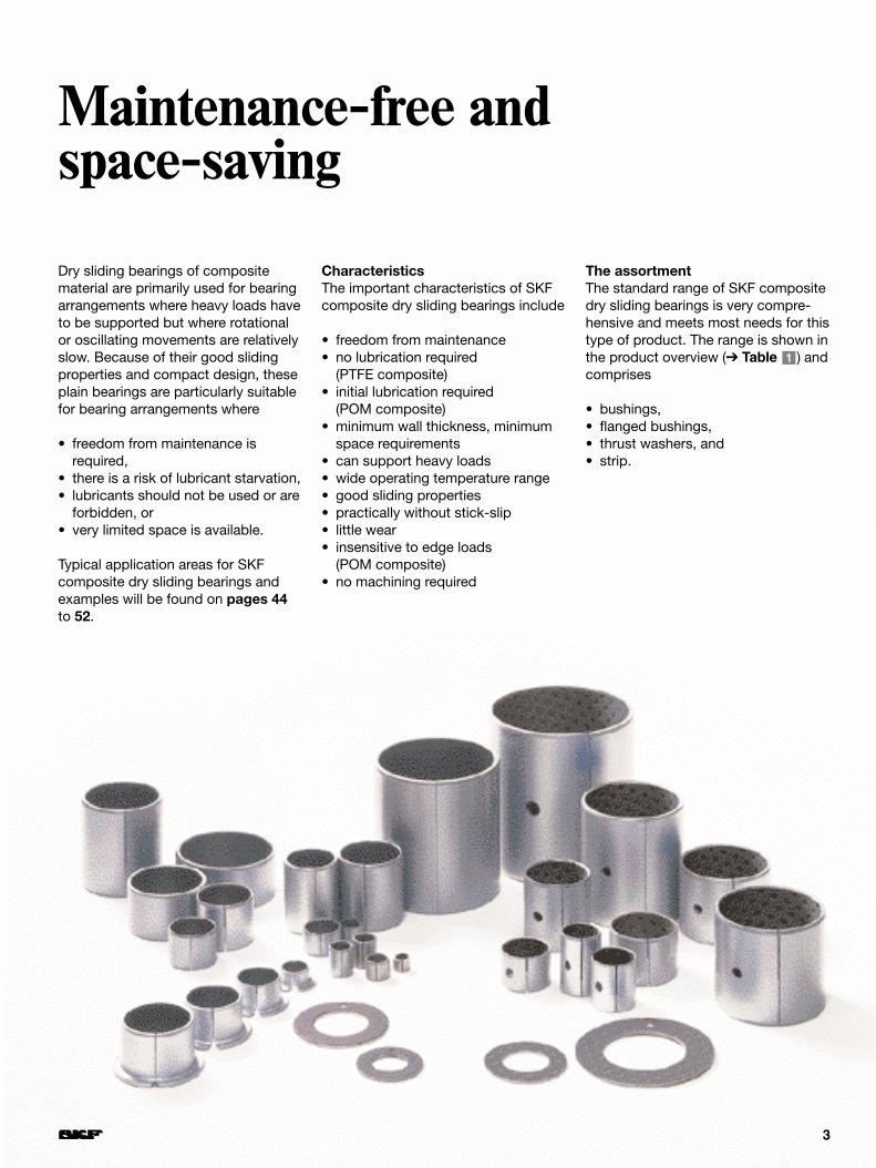
Dry sliding bearings of compositematerial are primarily used for bearingarrangements where heavy loads haveto be supported but where rotationalor oscillating movements are relativelyslow. Because of their good slidingproperties and compact design, theseplain bearings are particularly suitablefor bearing arrangements where
• freedom from maintenance isrequired,
• there is a risk of lubricant starvation,• lubricants should not be used or are
forbidden, or • very limited space is available.
Typical application areas for SKF composite dry sliding bearings andexamples will be found on pages 44to 52.
Maintenance-free and space-saving
CharacteristicsThe important characteristics of SKFcomposite dry sliding bearings include
• freedom from maintenance• no lubrication required
(PTFE composite)• initial lubrication required
(POM composite)• minimum wall thickness, minimum
space requirements• can support heavy loads• wide operating temperature range• good sliding properties• practically without stick-slip• little wear• insensitive to edge loads
(POM composite)• no machining required
The assortmentThe standard range of SKF compositedry sliding bearings is very compre-hensive and meets most needs for thistype of product. The range is shown inthe product overview (➔ Table ) andcomprises
• bushings,• flanged bushings,• thrust washers, and• strip.
1
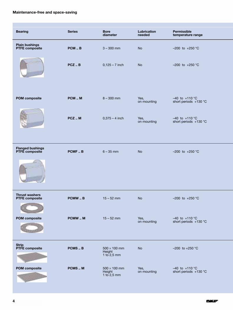
Bearing Series Bore Lubrication Permissiblediameter needed temperature range
Plain bushingsPTFE composite PCM .. B 3 – 300 mm No –200 to +250 °C
PCZ .. B 0,125 – 7 inch No –200 to +250 °C
POM composite PCM .. M 8 – 300 mm Yes, –40 to +110 °Con mounting short periods +130 °C
PCZ .. M 0,375 – 4 inch Yes, –40 to +110 °Con mounting short periods +130 °C
Flanged bushingsPTFE composite PCMF .. B 6 – 35 mm No –200 to +250 °C
Thrust washersPTFE composite PCMW .. B 15 – 52 mm No –200 to +250 °C
POM composite PCMW .. M 15 – 52 mm Yes, –40 to +110 °Con mounting short periods +130 °C
StripPTFE composite PCMS .. B 500 × 100 mm No –200 to +250 °C
Height1 to 2,5 mm
POM composite PCMS .. M 500 × 100 mm Yes, –40 to +110 °CHeight on mounting short periods +130 °C1 to 2,5 mm
4
Maintenance-free and space-saving
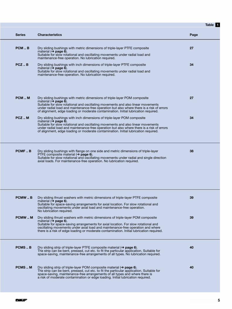
Series Characteristics Page
PCM .. B Dry sliding bushings with metric dimensions of triple-layer PTFE composite 27material (➔ page 6).Suitable for slow rotational and oscillating movements under radial load and maintenance-free operation. No lubrication required.
PCZ .. B Dry sliding bushings with inch dimensions of triple-layer PTFE composite 34material (➔ page 6).Suitable for slow rotational and oscillating movements under radial load and maintenance-free operation. No lubrication required.
PCM .. M Dry sliding bushings with metric dimensions of triple-layer POM composite 27material (➔ page 6).Suitable for slow rotational and oscillating movements and also linear movements under radial load and maintenance-free operation but also where there is a risk of errors of alignment, edge loading or moderate contamination. Initial lubrication required.
PCZ .. M Dry sliding bushings with inch dimensions of triple-layer POM composite 34material (➔ page 6).Suitable for slow rotational and oscillating movements and also linear movements under radial load and maintenance-free operation but also where there is a risk of errors of alignment, edge loading or moderate contamination. Initial lubrication required.
PCMF .. B Dry sliding bushings with flange on one side and metric dimensions of triple-layer 38PTFE composite material (➔ page 6).Suitable for slow rotational and oscillating movements under radial and single directionaxial loads. For maintenance-free operation. No lubrication required.
PCMW .. B Dry sliding thrust washers with metric dimensions of triple-layer PTFE composite 39material (➔ page 6).Suitable for space-saving arrangements for axial location. For slow rotational and oscillating movements under axial load and maintenance-free operation. No lubrication required.
PCMW .. M Dry sliding thrust washers with metric dimensions of triple-layer POM composite 39material (➔ page 6).Suitable for space-saving arrangements for axial location. For slow rotational and oscillating movements under axial load and maintenance-free operation and where there is a risk of edge loading or moderate contamination. Initial lubrication required.
PCMS .. B Dry sliding strip of triple-layer PTFE composite material (➔ page 6). 40The strip can be bent, pressed, cut etc. to fit the particular application. Suitable for space-saving, maintenance-free arrangements of all types. No lubrication required.
PCMS .. M Dry sliding strip of triple-layer POM composite material (➔ page 6). 40The strip can be bent, pressed, cut etc. to fit the particular application. Suitable for space-saving, maintenance-free arrangements of all types and where there is a risk of moderate contamination or edge loading. Initial lubrication required.
5
1Table

2Fig1Fig
6
Maintenance-free and space-saving
PTFE composite dry sliding material
MaterialsThere are two standard types of com-posite material for SKF dry slidingbearings: PTFE composite and POMcomposite, which differ in their slidinglayers. They are suitable in differentbearing applications.
PTFE compositeThe PTFE composite material has acopper-plated sheet steel backing onto which a 0,2 to 0,4 mm thick porouslayer of tin bronze is sintered (➔ fig ).The pores of the sintered layer arefilled with a mixture of PTFE (polytetra-fluoroethylene) and lead by a rollingprocess. The sintered bronze layer iscovered by a 5 to 30 µm thick running-in layer of the same mixture.
There is an optimum combination ofthe mechanical properties of the sin-tered bronze and the good sliding andlubricating properties of the PTFE mix-ture in PTFE composite bearings. Ithas good dimensional stability andthermal conductivity.
1
PTFE composite bearings are identi-fied by designation suffix B, e.g. PCM 101212 B.
POM compositeThe POM composite material also hasa sheet steel backing which is copperplated, and also a 0,2 to 0,4 mm thicklayer of sintered tin bronze (➔ fig ).The principal characteristic of thesebearings is their relatively thick (0,3 mm)covering layer of acetal resin (POM –polyoxymethylene) which is firmlyanchored in the sintered bronze layer.The covering layer has pockets toretain lubricating grease.
The thickness of the covering layermakes bearings insensitive to a certaindegree of misaligment and the edgeloading associated with misalignment.
POM composite bearings are identi-fied by designation suffix M, e.g. PCM 101212 M.
2
POM composite dry sliding material
polytetrafluoroethylene(PTFE) + lead
tin bronze
copper layer
sheet steel backing
copper layer
tin layer
polyoxymethylene(POM)
tin bronze
copper layer
sheet steel backing
copper layer
tin layer
7
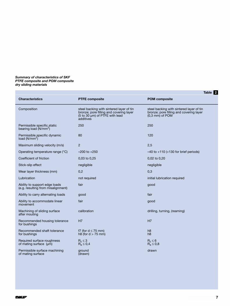
Characteristics PTFE composite POM composite
Composition steel backing with sintered layer of tin steel backing with sintered layer of tin bronze; pore filling and covering layer bronze; pore filling and covering layer (5 to 30 µm) of PTFE with lead (0,3 mm) of POM additives
Permissible specific static 250 250 bearing load (N/mm2)
Permissible specific dynamic 80 120 load (N/mm2)
Maximum sliding velocity (m/s) 2 2,5
Operating temperature range (°C) –200 to +250 –40 to +110 (+130 for brief periods)
Coefficient of friction 0,03 to 0,25 0,02 to 0,20
Stick-slip effect negligible negligible
Wear layer thickness (mm) 0,2 0,3
Lubrication not required initial lubrication required
Ability to support edge loads fair good(e.g. resulting from misalignment)
Ability to carry alternating loads good fair
Ability to accommodate linear fair goodmovement
Machining of sliding surface calibration drilling, turning, (reaming)after mouting
Recommended housing tolerance H7 H7for bushings
Recommended shaft tolerance f7 (for d ≤ 75 mm) h8for bushings h8 (for d > 75 mm) h8
Required surface roughness Rz ≤ 3 Rz ≤ 6of mating surface (µm) Ra ≤ 0,4 Ra ≤ 0,8
Permissible surface machining ground drawnof mating surface (drawn)
2Table
Summary of characteristics of SKF PTFE composite and POM composite dry sliding materials
3Fig
8
Maintenance-free and space-saving
Machinability of composite materials
SKF composite dry sliding bearingmaterials – with the exception of thesliding layer – can be machined usingconventional methods.
If bushings are required to have asmaller width than the standard size,this can easily be achieved by turningor parting-off. It is also possible to drilllubrication holes. Care must be takento see that any burrs are removed,particularly from the sliding surface.
Strip can be bent, coined, pressed,cut, bored or drilled to shape to fit theindividual application. When cutting ordrilling it is advisable to work from thesliding surface side to avoid creatingburrs in the sliding layer.
Any bright metal surfaces producedas a result of machining should begiven protection against corrosion.
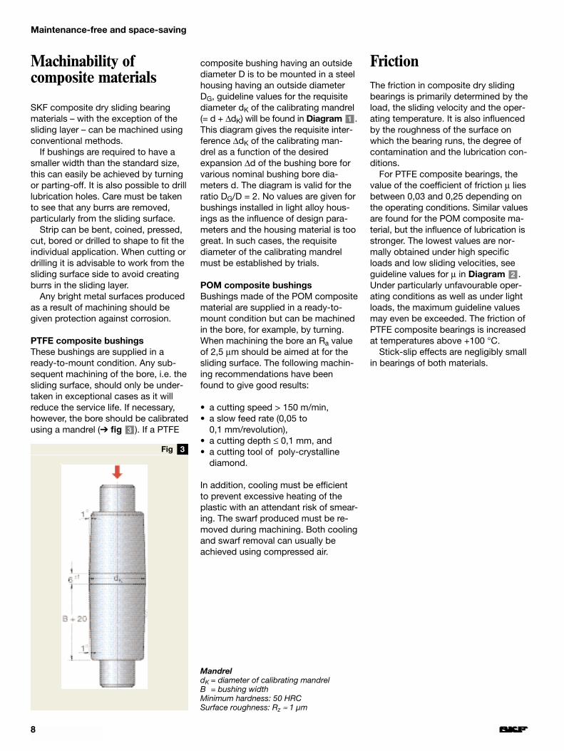
PTFE composite bushingsThese bushings are supplied in aready-to-mount condition. Any sub-sequent machining of the bore, i.e. thesliding surface, should only be under-taken in exceptional cases as it willreduce the service life. If necessary,however, the bore should be calibratedusing a mandrel (➔ fig ). If a PTFE3
composite bushing having an outsidediameter D is to be mounted in a steelhousing having an outside diameterDG, guideline values for the requisitediameter dK of the calibrating mandrel(= d + ∆dK) will be found in Diagram .This diagram gives the requisite inter-ference ∆dK of the calibrating man-drel as a function of the desiredexpansion ∆d of the bushing bore forvarious nominal bushing bore dia-meters d. The diagram is valid for theratio DG/D = 2. No values are given forbushings installed in light alloy hous-ings as the influence of design para-meters and the housing material is toogreat. In such cases, the requisitediameter of the calibrating mandrelmust be established by trials.
POM composite bushingsBushings made of the POM compositematerial are supplied in a ready-to-mount condition but can be machinedin the bore, for example, by turning.When machining the bore an Ra valueof 2,5 µm should be aimed at for thesliding surface. The following machin-ing recommendations have beenfound to give good results:
• a cutting speed > 150 m/min,• a slow feed rate (0,05 to
0,1 mm/revolution),• a cutting depth ≤ 0,1 mm, and• a cutting tool of poly-crystalline
diamond.
In addition, cooling must be efficientto prevent excessive heating of theplastic with an attendant risk of smear-ing. The swarf produced must be re-moved during machining. Both coolingand swarf removal can usually beachieved using compressed air.
1
FrictionThe friction in composite dry slidingbearings is primarily determined by theload, the sliding velocity and the oper-ating temperature. It is also influencedby the roughness of the surface onwhich the bearing runs, the degree ofcontamination and the lubrication con-ditions.
For PTFE composite bearings, thevalue of the coefficient of friction µ liesbetween 0,03 and 0,25 depending onthe operating conditions. Similar valuesare found for the POM composite ma-terial, but the influence of lubrication isstronger. The lowest values are nor-mally obtained under high specificloads and low sliding velocities, seeguideline values for µ in Diagram .Under particularly unfavourable oper-ating conditions as well as under lightloads, the maximum guideline valuesmay even be exceeded. The friction ofPTFE composite bearings is increasedat temperatures above +100 °C.
Stick-slip effects are negligibly smallin bearings of both materials.
2
MandreldK = diameter of calibrating mandrelB = bushing widthMinimum hardness: 50 HRCSurface roughness: Rz ≈ 1 µm

2Diagram
1Diagram
9
Requisite interference of the mandrel
Chemical propertiesThe chemical resistance of SKF com-posite dry sliding bearings is primarilydetermined by the chemical resistanceof the steel backing and the sinteredtin bronze layer, as the sliding (cover-ing) layers are chemically resistant tomany substances. The covering layerof the PTFE composite material is vir-tually inert because of its PTFE con-tent, although at elevated temperat-ures molten alkali metals and free fluorine will attack it. The acetal resincovering layer of the POM compositebearings is largely resistant to organicsubstances.
At room temperature the sintered tinbronze structure has good resistanceto sea water, steam, atmospheric in-fluences, salt solutions and sulphuricacid, but not to oxidising acids ormedia containing ammonia.
All exposed surfaces of the steelbacking are electrolytically tin platedbut this gives only limited protectionagainst corrosion in most applications.In cases where the bearings are to beexposed to corrosive media, or wherethere is a danger of corrosion in thecontact between the steel backing andthe housing material, the backing canbe protected by a nickel, chromium orzinc coating applied electrolytically.Further details can be supplied onrequest.
Guideline valuesfor coefficient offriction of PTFEcomposite dry sliding bearings
Valid for steel housings with DG/D = 2

1Diagram
10
Selection of bearing size
The load carrying ability and wearbehaviour of SKF composite dry slid-ing bearings are governed by the spe-cific conditions pertaining in a particu-lar application. Therefore, any calcula-tion can only provide approximate values. In order to determine the re-quired size of bearing, the load carry-ing capacity, the applied loads, the ser-vice life requirements and operationalreliability are all considered. The loadcarrying capacity is expressed by thebasic dynamic load rating C and thebasic static load rating C0. Values ofthe load ratings will be found in theproduct tables.
Basic load ratingsBasic dynamic load ratingsThe basic dynamic load rating C isused when calculating dry slidingbearings which are to be dynamicallyloaded. It is defined as that load, con-stant in magnitude and direction,under which a given basic rating life(corresponding to a given total dis-tance travelled) can be achieved underconstant rotation or oscillating move-ment at a defined sliding velocity atroom temperature. It is assumed inthis definition that the load acting onbushings and flanged bushings ispurely radial, and the load acting onthrust washers is purely axial andapplied at the centre. Dynamic loadconditions are essentially oscillatingmovement or rotation under load, but
also include micro-sliding under vari-able load (e.g. as a result of vibration)or operation under high-frequencyalternating loads. Often a combinationof these conditions will be encoun-tered. Whereas oscillating movementor rotation under load usually pro-duces wear, the other conditions mayresult in fatigue.
The actual load ratings quoted byvarious manufacturers depend on theway in which they are defined so thatit is not always possible to make directcomparisons between them.
Basic static load ratingsThe basic static load rating C0 isdefined as the maximum load whichan SKF composite bushing, flanged
bushing or thrust washer can supportwhen stationary at room temperaturewithout permanent deformation of thesliding layer being produced whichwould jeopardise its performance. It isassumed here that the componentssurrounding the bearing prevent itsdeformation. At elevated temperaturesit is necessary to modify the basicload ratings of the various materials bymultiplying the C0 value by the temper-ature factor c3, which is also valid fordynamically loaded bearings (➔ Dia-gram ). The permissible operatingtemperature range should also beconsidered (➔ Table ), page 7).2
5
pv operating range for PTFE compositedry sliding bearings
pv operating ranges
I Basic rating service life equation validII Quasi-static range;
SKF should be consulted before life equation is used III Operation possible, e.g. if heat removal very good;
SKF should be consulted before life equation is used
2Diagram
11
Service lifeThe service life of a dry sliding bearingis expressed as a number of oscilla-tions or revolutions, or in operatinghours. It depends on the clearanceincrease occurring under boundary ordry lubrication conditions because ofthe continuing wear of the sliding con-tact surfaces, plastic deformation ofthe sliding layer or fatigue. Dependingon the application and sliding layervarious degrees of wear or increasesin friction may be acceptable. Thismeans that even under apparentlysimilar operating conditions, the ser-vice life achieved in practice will differ,simply because the requirementsplaced on the bearing differ.
In contrast, the lives actuallyachieved by seemingly identical bear-ings under identical operating condi-tions for identical demands are not thesame. This scatter of results has been
found both in laboratory endurancetests as well as in field tests. Obvi-ously the actual lives will also beaffected by the actual operating con-ditions – not only the magnitude andtype of load but also many other in-fluences which are difficult or evenimpossible to quantify. These includecontamination, corrosion, high fre-quency load and movement cyclesand shock loads.
However, the basic rating service lifeis a guideline value which is attainedor exceeded by the majority of bear-ings under the test conditions.
Requisite bearing sizeThe type and mode of action of theload, the expected operating temper-ature, lubrication and maintenancerequirements etc. all influence thechoice of bearing type and design.
To determine the requisite size ofcomposite dry sliding bearing to beused, it is necessary to know the basicrating service life which is required for,or appropriate to, a given application.This depends on the type of machine,the duration of operation, the operat-ing conditions and the degree of opera-tional reliability required.
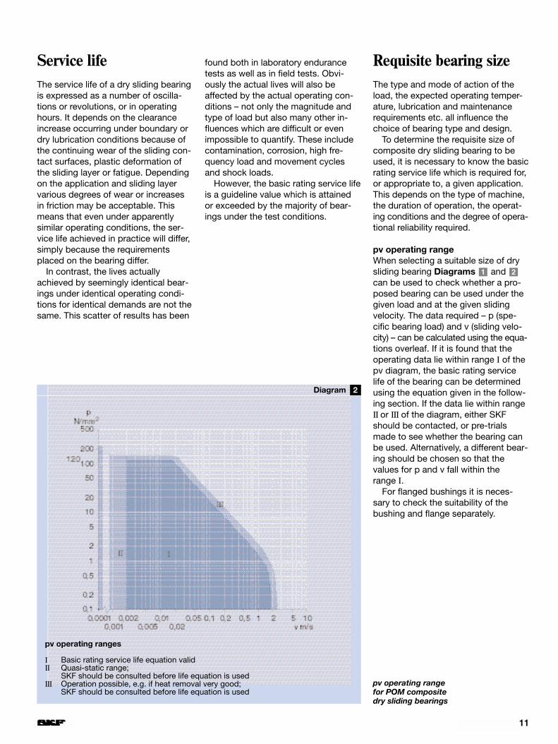
pv operating rangeWhen selecting a suitable size of drysliding bearing Diagrams and can be used to check whether a pro-posed bearing can be used under thegiven load and at the given slidingvelocity. The data required – p (spe-cific bearing load) and v (sliding velo-city) – can be calculated using the equa-tions overleaf. If it is found that theoperating data lie within range I of thepv diagram, the basic rating servicelife of the bearing can be determinedusing the equation given in the follow-ing section. If the data lie within rangeII or III of the diagram, either SKFshould be contacted, or pre-trialsmade to see whether the bearing canbe used. Alternatively, a different bear-ing should be chosen so that the values for p and v fall within the range I.
For flanged bushings it is neces-sary to check the suitability of thebushing and flange separately.
21
pv operating range for POM composite dry sliding bearings
pv operating ranges
I Basic rating service life equation validII Quasi-static range;
SKF should be consulted before life equation is used III Operation possible, e.g. if heat removal very good;
SKF should be consulted before life equation is used

3Diagram
4Diagram
5Diagram
6Diagram
12
Selection of bearing size
Determination of specific bearingloadThe specific bearing load can bedetermined from
Fp = K ––
C
wherep = specific bearing load, N/mm2
F = dynamic bearing load, NC = basic dynamic load rating, NK = specific load factor, N/mm2
= 80 for PTFE composite material= 120 for POM composite material
For flanged bushings it is necessary tocalculate the specific load of the bush-ing and flange separately. When calcu-lating the specific bearing load for theflange the axial basic dynamic loadrating Ca should be used instead of Cin the above equation. Values of Ca willbe found in the product tables.
Determination of sliding velocityThe sliding velocity for SKF compositebushings and thrust washers can beobtained from
v = 5,82 × 10⁻⁷ d β f
wherev = sliding velocity, m/sd = bore diameter of bushings and
flanged bushings, mm= mean diameter of flange of flanged
bushings = 0,5 (d + D1), mm= mean diameter of thrust washers
= 0,5 (d + D), mm (= dimension Jin product table)
f = frequency of oscillation, min–1, or rotational speed, r/min
β = half the angle of oscillation,degrees (➔ fig )A complete oscillation (from point0 to point 4) = 4 β. For rotation,use β = 90°.
1
Load factor c1
Speed factor c2
Temperature factor c3
Surface roughness factor c4
PTFE composite
POM composite
PTFE composite
POM composite
PTFE composite
POM composite
POM compositePTFE composite

1Fig
13
Calculation of servicelife
Many factors influence the life of a drysliding bearing, e.g. load, sliding velo-city, operating temperature, surfaceroughness of the surface on which thedry sliding layer runs etc. Any calcula-tion is therefore only approximate.
The values obtained using the equa-tions given below for the basic ratingservice life are attained by the majorityof bearings and are often exceeded.This has been confirmed by rig testsand field experience.
The basic rating service life for SKFPTFE composite and POM compositedry sliding bearings can be calculatedfrom
KMGh = c1 c2 c3 c4 c5 ––––(pv)n
whereGh = basic rating service life, operat-
ing hoursc1 = load factor (➔ Diagram )c2 = speed factor (➔ Diagram )c3 = temperature factor
(➔ Diagram )c4 = surface roughness factor
(➔ Diagram )c5 = factor for the type of load
= 1 for point load (i.e. the loadedzone is always at the same posi-tion on the bearing circumfer-ence) = 1,5 for rotating load (i.e. theloaded zone moves round thecircumference of the bearing)
KM = factor depending on materialand bearing type = 480 for PTFE composite bush-
ings= 300 for PTFE composite
thrust washers= 1 900 for POM composite
bushings and thrust washersp = specific bearing load, N/mm2
v = sliding velocity, m/sn = an exponent
= 1 for PTFE composite bush-ings and thrust washers
= 1 for pv ≤ 1 for POM compositebushings and thrust washers
= 3 for pv > 1 for POM compositebushings and thrust washers
6
5
43
If loads are very light and/or slidingvelocities very low and the value of theproduct pv • for PTFE composite bearings is less
than the limiting value of 0,025 thenthe limiting value pv = 0,025 shouldbe used for the life calculations.
• for POM composite bearings is lessthan the limiting value of 0,1 thenthe limiting value pv = 0,1 should beused for the life calculations.
Calculation exampleThe suspension of a rail vehicle is tobe equipped with composite dry slid-ing bearings at the linkage position ofthe springs; in this case bushingsarranged in pairs are to be used.
Design data:Pin diameter: d = 30 mmSurface roughness of pin: Ra = 0,4 µm
Operating data:Radial load at the linkage point: Fr = 18 750 NHalf angle of oscillation: β = 1°(➔ fig )Frequency of oscillation: f = 180 min–1
Operating temperature: t = 30 °C
Based on the design characteristics,PTFE composite bushing PCM 303420B having a basic dynamic load ratingC = 46 500 N is chosen. It is neces-sary to check that the bushing can beused under the given operating condi-tions and then to calculate the basicrating service life.
As a first check that the bearing sizeis suitable (➔ Diagram ) the specificbearing load p is calculated using
F 18 750p = K –– = 80 × ––––––––– ≈ 16 N/mm2
C 2 × 46 500
(with the specific load factor K = 80 forPTFE composite).
The sliding velocity is calculated using
v = 5,82 × 10⁻⁷ d β f
= 5,82 × 10–7 × 30 × 1 × 180
= 0,0031 m/s
1
1
These values are within the permiss-ible range I of the pv diagram for PTFEcomposite bearings. Furthermore
the load factor c1 = 1 (➔ Diagram ), the speed factor c2 = 1 (➔ Diagram ),the temperature factor c3 = 1 (➔ Diagram ),the surface roughness factor c4 = 0,6(➔ Diagram ), andthe factor for the type of load c5 = 1,5as the load is rotating.
The value of KM for PTFE compos-ite bushings = 480. Thus using thebasic rating service life equation forSKF composite dry sliding bearings
KMGh = c1 c2 c3 c4 c5 ––––(pv)n
480Gh = 1 × 1 × 1 × 0,6 ×1,5 × ––––––––––
16 × 0,0031
Gh = 8 700 operating hours
6
5
4
3
Angle of oscillationϕ = angle of oscillation = 2 βA complete oscillation = 4 β(from point 0 to point 4)

14
Material and surface finish of counterfacesThe factors which are most importantto consider when selecting the materialand surface finish of the counterface(the surface on which the bearingslides) are the loading conditions (load,angle of oscillation, type of movementetc.) and the environmental influences.
Where there is a risk of corrosion,the counterface must be sufficientlyresistant. Corrosion scars in the coun-terface and the products of corrosion(particulate contamination) increasethe surface roughness or are abrasive,thus increasing wear. In such casesthe use of stainless steel or a surfacetreatment such as hard chromium ornickel plating or electrolytic oxidationshould be considered.
For PTFE composite and POM com-posite dry sliding bearing arrange-ments soft carbon steels having aground surface are usually adequatefor the counterface. The surface rough-ness Ra (to DIN 4768:1990) should notexceed 0,4 µm for PTFE compositebearings and 0,8 µm for POM compos-ite bearings. The corresponding Rzvalues are 3 and 6 µm, respectively. Formore demanding applications the useof hardened shafts is recommended.These should have a surface hardnessof at least 50 HRC. Alternatively, hardchromium or nickel plating or someother form of surface treatment shouldbe considered. In all cases Ra shouldnot be greater than 0,3 µm (Rz ≤ 2 µm).The better the surface finish, the betterthe running properties and the less thewear (➔ Surface roughness factorc4, Diagram , page 12).6
Shaft and housing tolerancesIt is recommended that the seating inthe housing bore is machined to toler-ance H6 for PTFE composite andPOM composite dry sliding bushings(including flanged bushings) having abore diameter up to and including 4 mm, and to tolerance H7 for largerbearings. If this is done, after mount-ing, the bore diameter of the bushingand the clearance in the bearingarrangement will lie within the limitsquoted in Tables and for metricsizes of PTFE composite and POMcomposite dry sliding bushings, re-spectively, provided the shaft seatingalso has the recommended tolerance.
The shaft and housing limits for inch-sized bushings are given in Tablesand , respectively, together with thecorresponding limits for the bushingbore diameter after mounting and theoperating clearance.
The values quoted are for the oper-ating clearance at room temperature.If the operating temperature is higherthan this it is expected that the operat-ing clearance of
• PTFE composite bushings will bereduced by 0,0016 mm and
• POM composite bushings will bereduced by 0,005 mm
for every 20 °C temperature increase. The actual operating clearance can beincreased or decreased within the re-commended limits by matching shaftand housing bores having appropriatevalues within the specified limits.
If in certain applications very easyrunning is required, for example, or ifthe bearing is only lightly loaded, it isrecommended that maximum valuesfor the operating clearance should beaimed for.
The recommended tolerances andguideline limits quoted in the tables arevalid for steel and cast iron housings.
42
31
Where light alloy housings are used, agreater degree of interference may berequired because of the different ther-mal expansion characteristics. There isotherwise a risk that the greater ther-mal expansion of the housing would nolonger provide radial location for thebushing and that the operating clear-ance would be too large.
If it is not possible to adopt agreater interference for mounting rea-sons, or because of the force requiredto press the bushing into the housingbore, it is possible to use an adhesiveto retain the bushing in position. Inspecial cases it may be necessary, byselecting a suitable tolerance for theshaft, to prevent an inadmissibleincrease in operating clearance.
Application of bearings

Bushing dimensions Diameter limits OperatingBore Outside Wall Shaft Housing Bore diameter of clearancediameter diameter thickness (f7 for d ≤ 75 mm) bore mounted bushing or preload (–)
(h8 for d > 75 mm) (H7)d D max min max min max min max min min max
mm mm µm
3 4,5 0,750 0,730 3,000(h6) 2,994(h6) 4,508(H6) 4,500(H6) 3,048 3,000 0 544 5,5 0,750 0,730 4,000(h6) 3,992(h6) 5,508(H6) 5,500(H6) 4,048 4,000 0 565 7 1,007 0,981 4,990 4,978 7,015 7,000 5,053 4,986 –4 75
6 8 1,007 0,981 5,990 5,978 8,015 8,000 6,053 5,986 –4 757 9 1,007 0,981 6,987 6,972 9,015 9,000 7,053 6,986 –1 818 10 1,007 0,981 7,987 7,972 10,015 10,000 8,053 7,986 –1 81
10 12 1,007 0,981 9,987 9,972 12,018 12,000 10,056 9,986 –1 8412 14 1,007 0,981 11,984 11,966 14,018 14,000 12,056 11,986 2 9013 15 1,007 0,981 12,984 12,966 15,018 15,000 13,056 12,986 2 90
14 16 1,007 0,981 13,984 13,966 16,018 16,000 14,056 13,986 2 9015 17 1,007 0,981 14,984 14,966 17,018 17,000 15,056 14,986 2 9016 18 1,007 0,981 15,984 15,966 18,018 18,000 16,056 15,986 2 90
17 19 1,007 0,981 16,984 16,966 19,021 19,000 17,059 16,986 2 9318 20 1,007 0,981 17,984 17,966 20,021 20,000 18,059 17,986 2 9320 23 1,507 1,475 19,980 19,959 23,021 23,000 20,071 19,986 6 112
22 25 1,507 1,475 21,980 21,959 25,021 25,000 22,071 21,986 6 11224 27 1,507 1,475 23,980 23,959 27,021 27,000 24,071 23,986 6 12025 28 1,507 1,475 24,980 24,959 28,021 28,000 25,071 24,986 6 120
28 32 2,007 1,971 27,980 27,959 32,025 32,000 28,083 27,986 6 12430 34 2,007 1,971 29,980 29,959 34,025 34,000 30,083 29,986 6 12432 36 2,007 1,971 31,975 31,950 36,025 36,000 32,083 31,986 11 133
35 39 2,007 1,971 34,975 34,950 39,025 39,000 35,083 34,986 11 13337 40 1,507 1,475 36,975 36,950 40,025 40,000 37,075 36,986 11 12540 44 2,007 1,971 39,975 39,950 44,025 44,000 40,083 39,986 11 133
45 50 2,508 2,462 44,975 44,950 50,025 50,000 45,101 44,984 9 15150 55 2,508 2,462 49,975 49,950 55,030 55,000 50,106 49,984 14 16655 60 2,508 2,462 54,970 54,940 60,030 60,000 55,106 54,984 14 166
60 65 2,508 2,462 59,970 59,940 65,030 65,000 60,106 59,984 14 16665 70 2,508 2,462 64,970 64,940 70,030 70,000 65,106 64,984 14 16670 75 2,508 2,462 69,970 69,940 75,030 75,000 70,106 69,984 14 166
75 80 2,508 2,462 74,970 74,940 80,030 80,000 75,106 74,984 14 16680 85 2,490 2,440 80,000 79,954 85,035 85,000 80,155 80,020 20 20185 90 2,490 2,440 85,000 84,946 90,035 90,000 85,155 85,020 20 206
90 95 2,490 2,440 90,000 89,946 95,035 95,000 90,155 90,020 20 20695 100 2,490 2,440 95,000 94,946 100,035 100,000 95,155 95,020 20 206100 105 2,490 2,440 100,000 99,946 105,035 105,000 100,155 100,020 20 206
105 110 2,490 2,440 105,000 104,946 110,035 110,000 105,155 105,020 20 206110 115 2,490 2,440 110,000 109,946 115,035 115,000 110,155 110,020 20 206115 120 2,490 2,440 115,000 114,946 120,035 120,000 115,155 115,020 20 206
120 125 2,465 2,415 120,000 119,946 125,040 125,000 120,210 120,070 70 264125 130 2,465 2,415 125,000 124,937 130,040 130,000 125,210 125,070 70 273130 135 2,465 2,415 130,000 129,937 135,040 135,000 130,210 130,070 70 273
135 140 2,465 2,415 135,000 134,937 140,040 140,000 135,210 135,070 70 273140 145 2,465 2,415 140,000 139,937 145,040 145,000 140,210 140,070 70 273150 155 2,465 2,415 150,000 149,937 155,040 155,000 150,210 150,070 70 273
1Table
15
PTFE composite bushings (metric sizes)Shaft and housing tolerances, bearing clearance

Bushing dimensions Diameter limits OperatingBore Outside Wall Shaft Housing Bore diameter of clearancediameter diameter thickness (h8) bore mounted bushing or preload (–)
(H7)d D max min max min max min max min min max
mm mm µm
160 165 2,465 2,415 160,000 159,937 165,040 165,000 160,210 160,070 70 273180 185 2,465 2,415 180,000 179,937 185,046 185,000 180,216 180,070 70 279200 205 2,465 2,415 200,000 199,928 205,046 205,000 200,216 200,070 70 288
210 215 2,465 2,415 210,000 209,928 215,046 215,000 210,216 210,070 70 288220 225 2,465 2,415 220,000 219,928 225,046 225,000 220,216 220,070 70 288250 255 2,465 2,415 250,000 249,928 255,052 255,000 250,222 250,070 70 294
300 305 2,465 2,415 300,000 299,919 305,052 305,000 300,222 300,070 70 303
16
Application of bearings
1Continuation of Table
PTFE composite bushings (metric sizes)Shaft and housing tolerances, bearing clearance

17
Bushing dimensions Diameter limits OperatingBore Outside Wall Shaft Housing Bore diameter of clearancediameter diameter thickness bore mounted bushing or preload (–)
d D max min max min max min max min min max
inch/mm inch/mm µinch/µm
0,125 0,1875 0,0316 0,0308 0,1243 0,1236 0,1878 0,1873 0,1261 0,1241 –0,24 2,563,175 4,763 0,803 0,783 3,157 3,139 4,770 4,757 3,204 3,151 –6 65
0,1562 0,2188 0,0316 0,0308 0,1554 0,1547 0,2191 0,2186 0,157 0,1554 –0,04 2,763,969 5,556 0,803 0,783 3,947 3,929 5,565 5,552 3,999 3,946 –1 70
0,1875 0,25 0,0316 0,0308 0,1865 0,1858 0,2503 0,2497 0,1887 0,1865 –0,04 2,874,763 6,35 0,803 0,783 4,737 4,719 6,358 6,342 4,792 4,736 –1 73
0,25 0,3125 0,0316 0,0308 0,2490 0,2481 0,3128 0,3122 0,251 0,2490 –0,04 3,036,35 7,938 0,803 0,783 6,325 6,302 7,945 7,930 6,379 6,324 –1 77
0,3125 0,375 0,0316 0,0308 0,3115 0,3106 0,3753 0,3747 0,3137 0,3115 –0,04 3,077,938 9,525 0,803 0,783 7,912 7,889 9,533 9,517 7,967 7,911 –1 78
0,375 0,4687 0,0472 0,0461 0,3740 0,3731 0,4691 0,4684 0,3768 0,3741 0,04 3,709,525 11,906 1,198 1,172 9,500 9,477 11,915 11,897 9,571 9,501 1 94
0,4375 0,5312 0,0472 0,0461 0,4365 0,4355 0,5316 0,5309 0,4393 0,4366 0,08 3,8211,113 13,494 1,198 1,172 11,087 11,062 13,503 13,485 11,159 11,089 2 97
0,5 0,5937 0,0472 0,0461 0,4990 0,4980 0,5941 0,5934 0,5018 0,4991 0,04 3,8212,7 15,081 1,198 1,172 12,675 12,649 15,090 15,072 12,746 12,676 1 97
0,5625 0,6562 0,0472 0,0461 0,5615 0,5605 0,6566 0,6559 0,5643 0,5616 0,08 3,8214,288 16,669 1,198 1,172 14,262 14,237 16,678 16,660 14,334 14,264 2 97
0,625 0,7187 0,0472 0,0461 0,6240 0,6230 0,7192 0,7184 0,6269 0,6241 0,04 3,9415,875 18,256 1,198 1,172 15,850 15,824 18,268 18,247 15,924 15,851 1 100
0,6875 0,7812 0,0472 0,0461 0,6865 0,6865 0,7817 0,7809 0,6894 0,6866 0,08 3,9017,463 19,844 1,198 1,172 17,437 17,412 19,855 19,835 17,511 17,439 2 99
0,75 0,875 0,0627 0,0614 0,7491 0,7479 0,8755 0,8747 0,7527 0,7493 0,24 4,7619,05 22,225 1,592 1,560 19,027 18,997 22,238 22,217 19,118 19,033 6 121
0,875 1 0,0627 0,0614 0,8741 0,8729 1,0005 0,9997 0,8777 0,8743 0,24 4,7622,225 25,4 1,592 1,560 22,202 22,172 25,413 25,392 22,293 22,208 6 121
1 1,125 0,0627 0,0614 0,9991 0,9979 1,1256 1,1246 1,0028 0,9993 0,16 4,8425,4 28,575 1,592 1,560 25,377 25,347 28,590 28,565 25,470 25,381 4 123
1,125 1,2812 0,0784 0,077 1,1238 1,1226 1,2818 1,2808 1,1279 1,1240 0,20 5,2828,575 32,544 1,991 1,955 28,545 28,514 32,558 32,532 28,648 28,550 5 134
1,25 1,4062 0,0784 0,077 1,2488 1,2472 1,4068 1,4058 1,2529 1,2490 0,20 5,5731,75 35,719 1,991 1,955 31,720 31,679 35,733 35,707 31,823 31,725 5 144
1,375 1,5312 0,0784 0,077 1,3738 1,3722 1,5318 1,5308 1,3779 1,3740 0,20 5,5734,925 38,894 1,991 1,955 34,895 34,854 38,908 38,882 34,998 34,900 5 144
1,5 1,6562 0,0784 0,077 1,4988 1,4972 1,6568 1,6558 1,5029 1,4990 0,20 5,5738,1 42,069 1,991 1,955 38,070 38,029 42,083 42,057 38,173 38,075 5 144
1,625 1,7812 0,784 0,077 1,6238 1,6222 1,7818 1,7808 1,6279 1,6240 0,20 5,5741,275 45,244 1,991 1,955 41,245 41,204 45,258 45,232 41,348 41,250 5 144
1,75 1,9375 0,0939 0,0921 1,7487 1,7471 1,9381 1,9371 1,7539 1,7492 0,51 6,7744,45 49,213 2,386 2,340 44,417 44,376 49,228 49,202 44,548 44,430 13 172
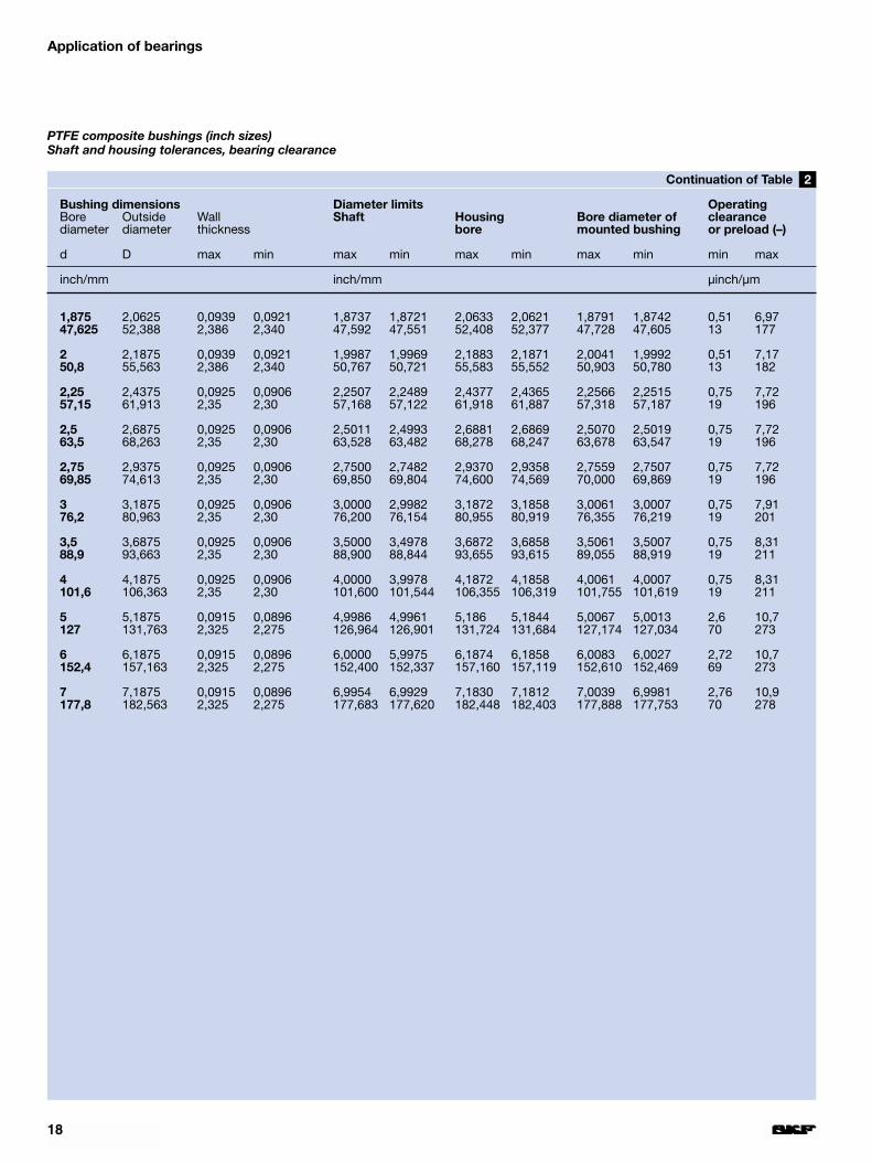
2Table
PTFE composite bushings (inch sizes)Shaft and housing tolerances, bearing clearance
18
Application of bearings
Bushing dimensions Diameter limits OperatingBore Outside Wall Shaft Housing Bore diameter of clearancediameter diameter thickness bore mounted bushing or preload (–)
d D max min max min max min max min min max
inch/mm inch/mm µinch/µm
1,875 2,0625 0,0939 0,0921 1,8737 1,8721 2,0633 2,0621 1,8791 1,8742 0,51 6,9747,625 52,388 2,386 2,340 47,592 47,551 52,408 52,377 47,728 47,605 13 177
2 2,1875 0,0939 0,0921 1,9987 1,9969 2,1883 2,1871 2,0041 1,9992 0,51 7,1750,8 55,563 2,386 2,340 50,767 50,721 55,583 55,552 50,903 50,780 13 182
2,25 2,4375 0,0925 0,0906 2,2507 2,2489 2,4377 2,4365 2,2566 2,2515 0,75 7,7257,15 61,913 2,35 2,30 57,168 57,122 61,918 61,887 57,318 57,187 19 196
2,5 2,6875 0,0925 0,0906 2,5011 2,4993 2,6881 2,6869 2,5070 2,5019 0,75 7,7263,5 68,263 2,35 2,30 63,528 63,482 68,278 68,247 63,678 63,547 19 196
2,75 2,9375 0,0925 0,0906 2,7500 2,7482 2,9370 2,9358 2,7559 2,7507 0,75 7,7269,85 74,613 2,35 2,30 69,850 69,804 74,600 74,569 70,000 69,869 19 196
3 3,1875 0,0925 0,0906 3,0000 2,9982 3,1872 3,1858 3,0061 3,0007 0,75 7,9176,2 80,963 2,35 2,30 76,200 76,154 80,955 80,919 76,355 76,219 19 201
3,5 3,6875 0,0925 0,0906 3,5000 3,4978 3,6872 3,6858 3,5061 3,5007 0,75 8,3188,9 93,663 2,35 2,30 88,900 88,844 93,655 93,615 89,055 88,919 19 211
4 4,1875 0,0925 0,0906 4,0000 3,9978 4,1872 4,1858 4,0061 4,0007 0,75 8,31101,6 106,363 2,35 2,30 101,600 101,544 106,355 106,319 101,755 101,619 19 211
5 5,1875 0,0915 0,0896 4,9986 4,9961 5,186 5,1844 5,0067 5,0013 2,6 10,7127 131,763 2,325 2,275 126,964 126,901 131,724 131,684 127,174 127,034 70 273
6 6,1875 0,0915 0,0896 6,0000 5,9975 6,1874 6,1858 6,0083 6,0027 2,72 10,7152,4 157,163 2,325 2,275 152,400 152,337 157,160 157,119 152,610 152,469 69 273
7 7,1875 0,0915 0,0896 6,9954 6,9929 7,1830 7,1812 7,0039 6,9981 2,76 10,9177,8 182,563 2,325 2,275 177,683 177,620 182,448 182,403 177,888 177,753 70 278
2Continuation of Table
PTFE composite bushings (inch sizes)Shaft and housing tolerances, bearing clearance
19
Bushing dimensions Diameter limits OperatingBore Outside Wall Shaft Housing Bore diameter of clearancediameter diameter thickness (h8) bore mounted bushing
(H7)d D max min max min max min max min min max
mm mm µm
8 10 0,980 0,955 8,000 7,978 10,015 10,000 8,105 8,040 40 12710 12 0,980 0,955 10,000 9,978 12,018 12,000 10,108 10,040 40 13012 14 0,980 0,955 12,000 11,973 14,018 14,000 12,108 12,040 40 135
13 15 0,980 0,955 13,000 12,973 15,018 15,000 13,108 13,040 40 13514 16 0,980 0,955 14,000 13,973 16,018 16,000 14,108 14,040 40 13515 17 0,980 0,955 15,000 14,973 17,018 17,000 15,108 15,040 40 135
16 18 0,980 0,955 16,000 15,973 18,018 18,000 16,108 16,040 40 13518 20 0,980 0,955 18,000 17,973 20,021 20,000 18,111 18,040 40 13820 23 1,475 1,445 20,000 19,967 23,021 23,000 20,131 20,050 50 164
22 25 1,475 1,445 22,000 21,967 25,021 25,000 22,131 22,050 50 16424 27 1,475 1,445 24,000 23,967 27,021 27,000 24,131 24,050 50 16425 28 1,475 1,445 25,000 24,967 28,021 28,000 25,131 25,050 50 164
28 32 1,970 1,935 28,000 27,967 32,025 32,000 28,155 28,060 60 18830 34 1,970 1,935 30,000 29,967 34,025 34,000 30,155 30,060 60 18832 36 1,970 1,935 32,000 31,961 36,025 36,000 32,155 32,060 60 194
35 39 1,970 1,935 35,000 34,961 39,025 39,000 35,155 35,060 60 19437 40 1,475 1,445 37,000 36,961 40,025 40,000 37,135 37,050 50 17440 44 1,970 1,935 40,000 39,961 44,025 44,000 40,155 40,060 60 194
45 50 2,460 2,415 45,000 44,961 50,025 50,000 45,195 45,080 80 23450 55 2,460 2,415 50,000 49,961 55,030 55,000 50,200 50,080 80 23955 60 2,460 2,415 55,000 54,954 60,030 60,000 55,200 55,080 80 246
60 65 2,460 2,415 60,000 59,954 65,030 65,000 60,200 60,080 80 24665 70 2,450 2,385 65,000 64,954 70,030 70,000 65,260 65,100 100 30670 75 2,450 2,385 70,000 69,954 75,030 75,000 70,260 70,100 100 306
75 80 2,450 2,385 75,000 74,954 80,030 80,000 75,260 75,100 100 30680 85 2,450 2,385 80,000 79,954 85,035 85,000 80,265 80,100 100 31185 90 2,450 2,385 85,000 84,946 90,035 90,000 85,265 85,100 100 319
90 95 2,450 2,385 90,000 89,946 95,035 95,000 90,265 90,100 100 31995 100 2,450 2,385 95,000 94,946 100,035 100,000 95,265 95,100 100 319100 105 2,450 2,385 100,000 99,946 105,035 105,000 100,265 100,100 100 319
105 110 2,450 2,385 105,000 104,946 110,035 110,000 105,265 105,100 100 319110 115 2,450 2,385 110,000 109,946 115,035 115,000 110,265 110,100 100 319115 120 2,450 2,385 115,000 114,946 120,035 120,000 115,265 115,100 100 319
120 125 2,450 2,385 120,000 119,946 125,040 125,000 120,270 120,100 100 324125 130 2,450 2,385 125,000 124,937 130,040 130,000 125,270 125,100 100 333130 135 2,450 2,385 130,000 129,937 135,040 135,000 130,270 130,100 100 333
135 140 2,450 2,385 135,000 134,937 140,040 140,000 135,270 135,100 100 333140 145 2,450 2,385 140,000 130,937 145,040 145,000 140,270 140,100 100 333150 155 2,450 2,385 150,000 149,937 155,040 155,000 150,270 150,100 100 333
160 165 2,450 2,385 160,000 159,937 165,040 165,000 160,270 160,100 100 333180 185 2,450 2,385 180,000 179,937 185,046 185,000 180,276 180,100 100 339190 195 2,450 2,385 190,000 189,928 195,046 195,000 190,276 190,100 100 348
210 215 2,450 2,385 210,000 209,928 215,046 215,000 210,276 210,100 100 348280 285 2,450 2,385 280,000 279,919 285,052 285,000 280,282 280,100 100 363
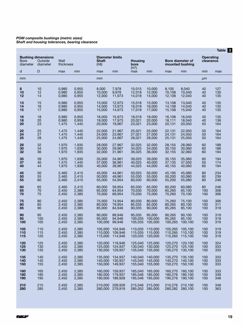
3Table
POM composite bushings (metric sizes)Shaft and housing tolerances, bearing clearance
Bushing dimensions Diameter limits OperatingBore Outside Wall Shaft Housing Bore diameter of clearancediameter diameter thickness bore mounted bushing
d D max min max min max min max min min max
inch/mm inch/mm µinch/µm
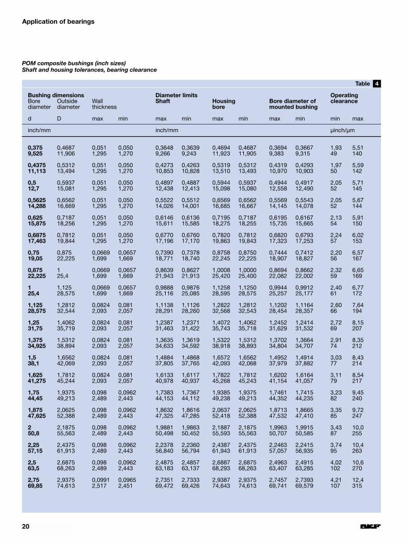
0,375 0,4687 0,051 0,050 0,3648 0,3639 0,4694 0,4687 0,3694 0,3667 1,93 5,519,525 11,906 1,295 1,270 9,266 9,243 11,923 11,905 9,383 9,315 49 140
0,4375 0,5312 0,051 0,050 0,4273 0,4263 0,5319 0,5312 0,4319 0,4293 1,97 5,5911,113 13,494 1,295 1,270 10,853 10,828 13,510 13,493 10,970 10,903 50 142
0,5 0,5937 0,051 0,050 0,4897 0,4887 0,5944 0,5937 0,4944 0,4917 2,05 5,7112,7 15,081 1,295 1,270 12,438 12,413 15,098 15,080 12,558 12,490 52 145
0,5625 0,6562 0,051 0,050 0,5522 0,5512 0,6569 0,6562 0,5569 0,5543 2,05 5,6714,288 16,669 1,295 1,270 14,026 14,001 16,685 16,667 14,145 14,078 52 144
0,625 0,7187 0,051 0,050 0,6146 0,6136 0,7195 0,7187 0,6195 0,6167 2,13 5,9115,875 18,256 1,295 1,270 15,611 15,585 18,275 18,255 15,735 15,665 54 150
0,6875 0,7812 0,051 0,050 0,6770 0,6760 0,7820 0,7812 0,6820 0,6793 2,24 6,0217,463 19,844 1,295 1,270 17,196 17,170 19,863 19,843 17,323 17,253 57 153
0,75 0,875 0,0669 0,0657 0,7390 0,7378 0,8758 0,8750 0,7444 0,7412 2,20 6,5719,05 22,225 1,699 1,669 18,771 18,740 22,245 22,225 18,907 18,827 56 167
0,875 1 0,0669 0,0657 0,8639 0,8627 1,0008 1,0000 0,8694 0,8662 2,32 6,6522,225 25,4 1,699 1,669 21,943 21,913 25,420 25,400 22,082 22,002 59 169
1 1,125 0,0669 0,0657 0,9888 0,9876 1,1258 1,1250 0,9944 0,9912 2,40 6,7725,4 28,575 1,699 1,669 25,116 25,085 28,595 28,575 25,257 25,177 61 172
1,125 1,2812 0,0824 0,081 1,1138 1,1126 1,2822 1,2812 1,1202 1,1164 2,60 7,6428,575 32,544 2,093 2,057 28,291 28,260 32,568 32,543 28,454 28,357 66 194
1,25 1,4062 0,0824 0,081 1,2387 1,2371 1,4072 1,4062 1,2452 1,2414 2,72 8,1531,75 35,719 2,093 2,057 31,463 31,422 35,743 35,718 31,629 31,532 69 207
1,375 1,5312 0,0824 0,081 1,3635 1,3619 1,5322 1,5312 1,3702 1,3664 2,91 8,3534,925 38,894 2,093 2,057 34,633 34,592 38,918 38,893 34,804 34,707 74 212
1,5 1,6562 0,0824 0,081 1,4884 1,4868 1,6572 1,6562 1,4952 1,4914 3,03 8,4338,1 42,069 2,093 2,057 37,805 37,765 42,093 42,068 37,979 37,882 77 214
1,625 1,7812 0,0824 0,081 1,6133 1,6117 1,7822 1,7812 1,6202 1,6164 3,11 8,5441,275 45,244 2,093 2,057 40,978 40,937 45,268 45,243 41,154 41,057 79 217
1,75 1,9375 0,098 0,0962 1,7383 1,7367 1,9385 1,9375 1,7461 1,7415 3,23 9,4544,45 49,213 2,489 2,443 44,153 44,112 49,238 49,213 44,352 44,235 82 240
1,875 2,0625 0,098 0,0962 1,8632 1,8616 2,0637 2,0625 1,8713 1,8665 3,35 9,7247,625 52,388 2,489 2,443 47,325 47,285 52,418 52,388 47,532 47,410 85 247
2 2,1875 0,098 0,0962 1,9881 1,9863 2,1887 2,1875 1,9963 1,9915 3,43 10,050,8 55,563 2,489 2,443 50,498 50,452 55,593 55,563 50,707 50,585 87 255
2,25 2,4375 0,098 0,0962 2,2378 2,2360 2,4387 2,4375 2,2463 2,2415 3,74 10,457,15 61,913 2,489 2,443 56,840 56,794 61,943 61,913 57,057 56,935 95 263
2,5 2,6875 0,098 0,0962 2,4875 2,4857 2,6887 2,6875 2,4963 2,4915 4,02 10,663,5 68,263 2,489 2,443 63,183 63,137 68,293 68,263 63,407 63,285 102 270
2,75 2,9375 0,0991 0,0965 2,7351 2,7333 2,9387 2,9375 2,7457 2,7393 4,21 12,469,85 74,613 2,517 2,451 69,472 69,426 74,643 74,613 69,741 69,579 107 315
20
Application of bearings
4Table
POM composite bushings (inch sizes)Shaft and housing tolerances, bearing clearance
21
Bushing dimensions Diameter limits OperatingBore Outside Wall Shaft Housing Bore diameter of clearancediameter diameter thickness bore mounted bushing
d D max min max min max min max min min max
inch/mm inch/mm µinch/µm
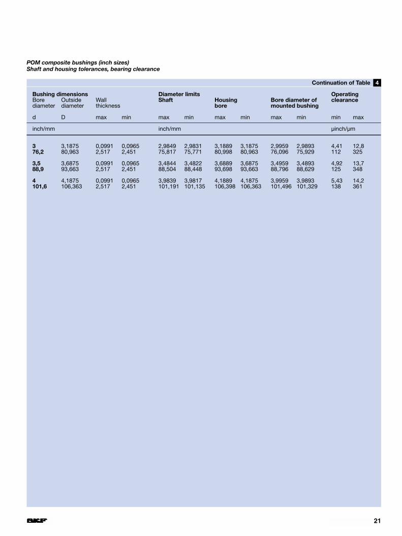
3 3,1875 0,0991 0,0965 2,9849 2,9831 3,1889 3,1875 2,9959 2,9893 4,41 12,876,2 80,963 2,517 2,451 75,817 75,771 80,998 80,963 76,096 75,929 112 325
3,5 3,6875 0,0991 0,0965 3,4844 3,4822 3,6889 3,6875 3,4959 3,4893 4,92 13,788,9 93,663 2,517 2,451 88,504 88,448 93,698 93,663 88,796 88,629 125 348
4 4,1875 0,0991 0,0965 3,9839 3,9817 4,1889 4,1875 3,9959 3,9893 5,43 14,2101,6 106,363 2,517 2,451 101,191 101,135 106,398 106,363 101,496 101,329 138 361
4Continuation of Table
POM composite bushings (inch sizes)Shaft and housing tolerances, bearing clearance

1Fig 2Fig
Lead-in chamfers for housing bores andshaft ends
22
3Fig
Application of bearings
Design of associatedcomponents
BushingsThe surface of the shaft on which thebushing runs, i.e. the counterface,should always be wider than the ac-tual bushing – particularly where axialdisplacement of the shaft relative tothe housing may occur as a result ofchanges in shaft length – in order toprevent step formation in the slidingsurface.
To ease mounting, shaft ends andhousing bores should have a lead-inchamfer with an angle of 10 to 15°(➔ fig ). It is then easier to press thebushings into the housing bore and toinsert the shaft into the bushing borewithout the risk of damaging the slid-ing surface.
The housing shoulders intended foraxial location of the bushing shouldhave a diameter which is equal to orgreater than d + 0,8 mm.
Where PTFE composite bushingsoperate without lubricant it is especial-ly important to accurately align bear-ing positions. If misalignment betweenthe positions cannot be avoided, it isnecessary to take steps at the designstage to prevent inadmissibly highedge stresses from occurring. For
1
example, the housing bore seatingshould be relieved at both sides, or awider bushing should be used so thatit extends beyond the housing boreseating at both sides (➔ fig ).
If errors of alignment have to becompensated for and the operatingconditions permit the use of POM com-posite, then bushings of this materialshould be chosen. The covering layerof this material can be machined to aminimum degree after the bushing hasbeen mounted in a housing bore.
Flanged bushings and thrust washersFor shafts which not only need radialsupport, but also require axial loca-tion, flanged bushings or a combina-tion of bushing and thrust washer (➔ fig ) can be used, depending onthe magnitude of the axial load. Theuse of flanged bushings or thrustwashers is advantageous even whereaxial loads are small, particularlywhere suitable surfaces are not avail-able to take the thrust, either becausethe material or its finish is unsuitable.
It should be remembered that thecounterface should completely coverthe sliding surface of the thrust washerand the flange of a flanged bushing (➔ fig ). For bearing arrangementswhere flanged bushings are used the
4
3
2
transition from housing bore to abut-ment should be chamfered so that itdoes not contact the bushing at thetransition to the flange (➔ fig ).
Thrust washers are generally locat-ed radially in a turned recess in thehousing (➔ fig ) and secured by adowel pin or grub screw to preventthem from rotating. The appropriatedimensions for this type of location aregiven in the product tables. If a recesscannot be provided in the housing forsome reason, the thrust washer canbe attached to the housing by twopins or screws (➔ fig ) or by glue-ing. The heads of the pins or screwsmust be recessed to at least 0,3 mmbelow the sliding surface and the en-tire surface of the thrust washer mustbe supported.
6
3
5
Bushing extending beyond the bearingseating in the housing at both sides toprevent inadmissibly high edge stresses
Combination of bushing and thrustwasher

9Fig
23
8Fig7
65
Fig
FigFig
SealsThe service life of composite dry slid-ing bearings is decisively influencedby the seals used. When selectingsuitable seals it is necessary to con-sider, for example, the design, theavailable space and the justifiableexpense.
Composite dry sliding bearings, inparticular those of the POM compos-ite, are able to embed contaminantparticles and are thus relatively insens-itive to contamination. They generallyrequire no special protection againstnormal airborne dirt. If, however, thebearing position is subjected to heav-ier contamination it should be sealedoff from the outside. Simple and effi-
cient sealing can be obtained if adja-cent components can also serve asseals (➔ fig ). Radial shaft sealswith low cross section, e.g. of the Gdesign, provide adequate protectionfor composite dry sliding bearings innormal cases (➔ fig ). If the de-mands placed on the sealing arrange-ment are high, it may be necessary to resort to special seals of rubber,plastic or similar materials (➔ fig ).
Under very rough conditions, par-ticularly where sand or clay contam-inants occur, rubber or plastic sealsusually have a very short life. Good“sealing” will be achieved in suchcases by periodic relubrication, if theoperating conditions permit.
9
8
7
The mating surface should cover theentire surface of the flange
The transition between housing boreand support surface must be sufficientlylarge
Thrust washer secured by two grubscrews
Adjacent components serve as sealsA shaft seal with low cross sectionalheight can be used
Sealing with a wiper-scraper seal ofnitrile rubber
4Fig
1Fig
24
Lubrication
PTFE composite bearings PTFE composite bearings have gooddry sliding characteristics and do notrequire lubrication. The presence orcontinuous supply of oil or other fluidmay be advantageous, however. Evenfluids not normally associated with lub-rication, such as water, kerosene orparaffin, may be used.
Lubrication improves the removal ofheat from the bearing position and theformation of a hydrodynamic lubricat-ing film has a very favourable effect onthe wear behaviour of the bearing andconsiderably extends bearing life.
If periodic relubrication with greaseis used to enhance sealing or to pro-tect the counterface against corrosion,bearing life will also be extended. Asingle initial application of grease whenmounting PTFE composite bearingsmay, however, have a negative influ-ence on bearing life, as the grease willform a paste-like mixture with the wearparticles produced during running in.This “paste” will increase bearingwear.
Age-resistant lithium base greasesare preferred for operating temperat-ures up to 80 °C, while at higher tem-peratures, silicone greases should beused. Greases containing solid lubric-ants such as molybdenum disulphideare totally unsuitable.
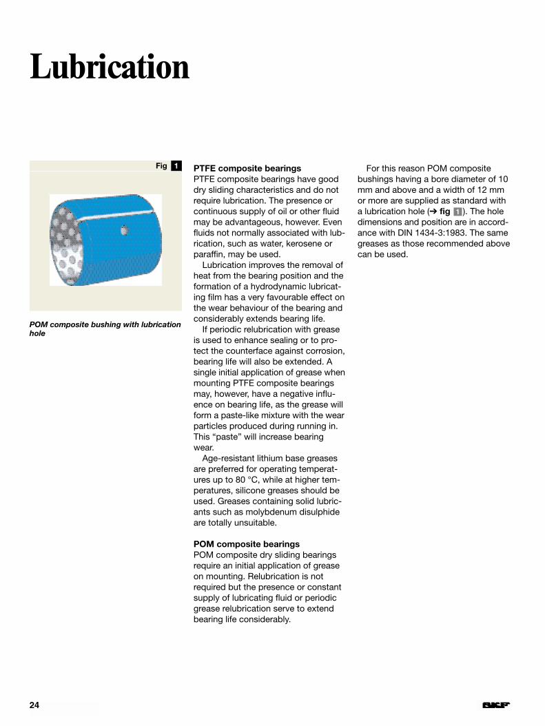
POM composite bearingsPOM composite dry sliding bearingsrequire an initial application of greaseon mounting. Relubrication is notrequired but the presence or constantsupply of lubricating fluid or periodicgrease relubrication serve to extendbearing life considerably.
For this reason POM compositebushings having a bore diameter of 10mm and above and a width of 12 mmor more are supplied as standard witha lubrication hole (➔ fig ). The holedimensions and position are in accord-ance with DIN 1434-3:1983. The samegreases as those recommended abovecan be used.
1
POM composite bushing with lubricationhole
3Fig
1Fig 2Fig
25
Skill and care in mounting are pre-requisites for the successful perform-ance of bearings and the avoidance ofpremature wear.
The counterface (shaft seating) andother components of the bearingarrangement should be carefullycleaned and deburred before mount-ing is begun. Unmachined surfaces incast iron housings must be free ofsand. The condition of the shaftshould be carefully checked so thatthere are no sharp edges or burrs orsurface defects which would damagethe sliding surface of the bushings asthey are mounted.
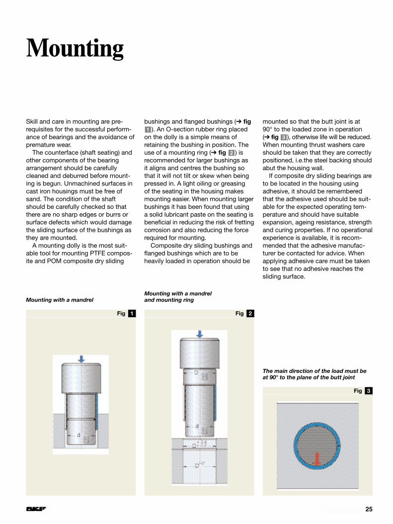
A mounting dolly is the most suit-able tool for mounting PTFE compos-ite and POM composite dry sliding
bushings and flanged bushings (➔ fig). An O-section rubber ring placed
on the dolly is a simple means ofretaining the bushing in position. Theuse of a mounting ring (➔ fig ) isrecommended for larger bushings as it aligns and centres the bushing sothat it will not tilt or skew when beingpressed in. A light oiling or greasing of the seating in the housing makesmounting easier. When mounting largerbushings it has been found that usinga solid lubricant paste on the seating isbeneficial in reducing the risk of frettingcorrosion and also reducing the forcerequired for mounting.
Composite dry sliding bushings andflanged bushings which are to beheavily loaded in operation should be
2
1mounted so that the butt joint is at 90° to the loaded zone in operation (➔ fig ), otherwise life will be reduced.When mounting thrust washers careshould be taken that they are correctlypositioned, i.e.the steel backing shouldabut the housing wall.
If composite dry sliding bearings areto be located in the housing usingadhesive, it should be rememberedthat the adhesive used should be suit-able for the expected operating tem-perature and should have suitableexpansion, ageing resistance, strengthand curing properties. If no operationalexperience is available, it is recom-mended that the adhesive manufac-turer be contacted for advice. Whenapplying adhesive care must be takento see that no adhesive reaches thesliding surface.
3
Mounting
Mounting with a mandrelMounting with a mandrel and mounting ring
The main direction of the load must beat 90° to the plane of the butt joint
washer) followed by 6 to 9 figures giv-ing the dimensions (d, D, B/H) in milli-metres uncoded. The small bushingscarrying the additional suffix /VB055are an exception to this: the outsidediameter is 0,5 mm larger than indic-ated in the designation. The actualmaterial used is identified by a suffix:B for PTFE composite and M for POMcomposite. For example, PCM 081008M is a POM composite bushing with d = 8 mm, D = 10 mm and B = 8 mm.
The inch-size bearings have similardesignations, but in this case the pre-fix is PCZ and the size (d, B) is shownin 1/16ths of an inch, e.g. PCZ 1208 Bis a PTFE composite bushing with d =12/16˝ = 3/4˝ and B = 8/16˝ = 1/2˝.
DimensionsThe dimensions of the metric sizes ofPTFE composite and POM compositedry sliding bushings in the bore dia-meter range 4 to 160 mm, inclusive,are in accordance, with a few excep-tions, with those specified in ISO3547-1976 and DIN 1494/1:1983.
The dimensions of the inch-sizebushings, the flanged bushings andthe thrust washers have not beenstandardised.
TolerancesBushings: The tolerances for the out-side diameter of the metric sizes ofSKF PTFE composite and POM com-posite dry sliding bushings correspondto DIN 1494/1:1983. To check the values, the procedure given in DIN1494/2:1983 should be used. For allsizes, the tolerances for the width Bare a uniform ± 0,25 mm.
Flanged bushings: For all sizes,when mounted, the tolerances are auniform ±0,5 mm for the flange dia-meter D1 and for the width B1+0,05/–0,20 mm.
Thrust washers: The tolerances forthe diameters are given in the producttable. The tolerances for the height are
• 0/–0,05 mm for PTFE compositethrust washers
• 0/–0,10 mm for POM compositethrust washers.
Strip: The tolerances for the height are
• 0/–0,05 mm for PTFE compositestrip
• 0/–0,10 mm for POM compositestrip
Operating clearanceThe operating clearance of bushingsdepends on the recommended shaftand housing tolerances. Guideline values for bushings in metric sizes are
26
Bearing data – general
given in Tables and and forinch-sized bushings in Tables and
. Excessive clearance may have a
negative influence on the service life ofPTFE composite bushings if they arenot lubricated.
Permissible operating temperaturerangePTFE composite dry sliding bearingscan be used at temperatures between–200 and +250 °C.
The operating temperature range forPOM composite bearings is –40 to+110 °C, although brief periods ofoperation at +130 °C are permissible.
The service life of SKF compositedry sliding bearings will be shortenedwhen operating at temperatures abovea given value. This is taken intoaccount when calculating the basicrating service life by the temperaturefactor c3 (➔ Diagram , page 12).
Running-inDuring a short running-in phase therewill be some transfer of material fromthe covering layer of bearings madefrom PTFE composite to the counter-face. After this transfer has taken place,the characteristic low friction and wearproperties of these bearings will beobtained.
Electrical propertiesBearings made from POM composite,because of their acetal resin coveringlayer, may act as electrical insulatorswhen new. To avoid the build-up ofstatic electricity, components at riskshould be earthed.
Product designationsSKF metric composite dry sliding bear-ings are identified by designationsmade up of a prefix PCM which mayhave a fourth letter indicating the typeof bearing (e.g. PCMW for a thrust
5
42
31

27
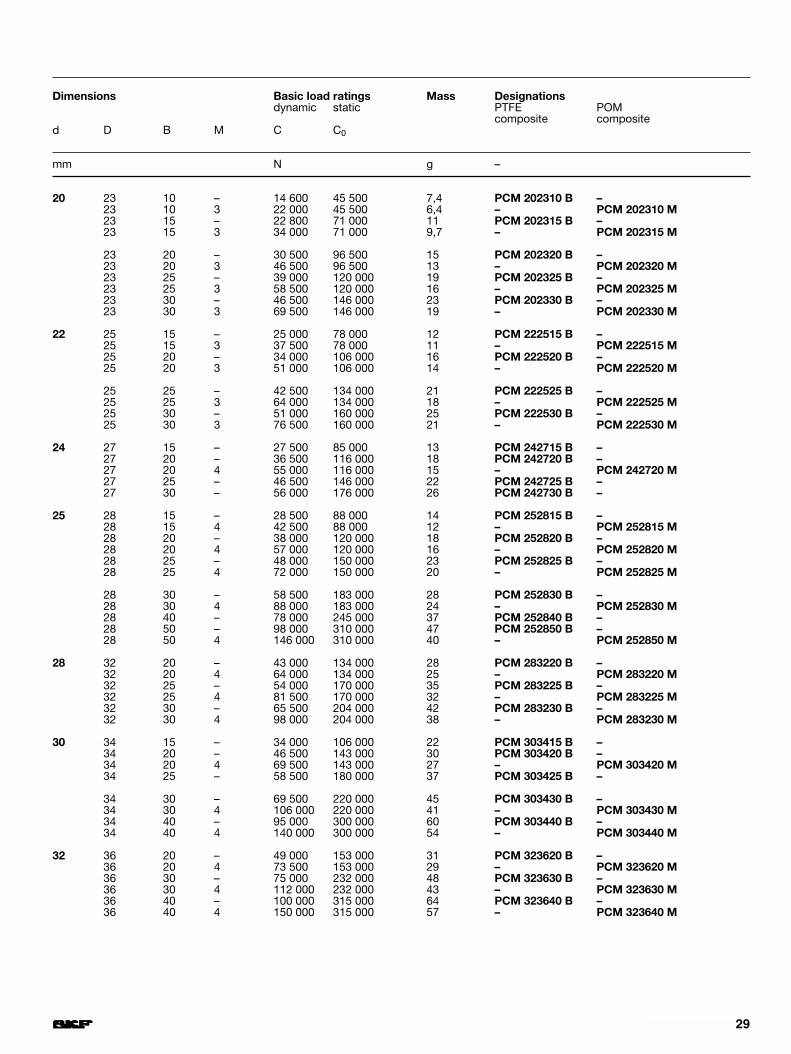
Dimensions Basic load ratings Mass Designationsdynamic static PTFE POM
composite composited D B M C C0
mm N g –
3 4,5 3 – 720 2 240 0,2 PCM 030403 B/VB055 –4,5 5 – 1 200 3 750 0,3 PCM 030405 B/VB055 –4,5 6 – 1 430 4 500 0,4 PCM 030406 B/VB055 –
4 5,5 3 – 965 3 000 0,2 PCM 040503 B/VB055 –5,5 4 – 1 270 4 000 0,3 PCM 040504 B/VB055 –5,5 6 – 1 930 6 000 0,6 PCM 040506 B/VB055 –5,5 10 – 3 200 10 000 0,8 PCM 040510 B/VB055 –
5 7 5 – 2 000 6 200 0,7 PCM 050705 B –7 8 – 3 200 10 000 1,1 PCM 050708 B –7 10 – 4 000 12 500 1,4 PCM 050710 B –
6 8 6 – 2 900 9 000 1,0 PCM 060806 B –8 8 – 3 800 12 000 1,3 PCM 060808 B –8 10 – 4 800 15 000 1,6 PCM 060810 B –
7 9 10 – 5 600 17 600 1,8 PCM 070910 B –
8 10 6 – 3 800 12 000 1,2 PCM 081006 B –10 8 – 5 100 16 000 1,7 PCM 081008 B –10 8 – 7 650 16 000 1,3 – PCM 081008 M10 10 – 6 400 20 000 2,1 PCM 081010 B –10 10 – 9 650 20 000 1,6 – PCM 081010 M10 12 – 7 650 24 000 2,5 PCM 081012 B –10 12 – 11 600 24 000 1,9 – PCM 081012 M
10 12 8 – 6 400 20 000 2,0 PCM 101208 B –12 10 – 8 000 25 000 2,5 PCM 101210 B –12 10 – 12 000 25 000 1,9 – PCM 101210 M12 12 – 9 650 30 000 3,0 PCM 101212 B –12 12 3 14 300 30 000 2,3 – PCM 101212 M
12 15 – 12 000 37 500 3,8 PCM 101215 B –12 15 3 18 000 37 500 2,9 – PCM 101215 M12 20 – 16 000 50 000 5,1 PCM 101220 B –12 20 3 24 000 50 000 3,9 – PCM 101220 M
12 14 8 – 7 650 24 000 2,4 PCM 121408 B –14 10 – 9 650 30 000 3,0 PCM 121410 B –14 10 3 14 300 30 000 2,3 – PCM 121410 M14 12 – 11 600 36 000 3,6 PCM 121412 B –14 12 3 17 300 36 000 2,8 – PCM 121412 M
14 15 – 14 300 45 000 4,5 PCM 121415 B –14 15 3 21 600 45 000 3,5 – PCM 121415 M14 20 – 19 300 60 000 6,0 PCM 121420 B –14 20 3 29 000 60 000 4,6 – PCM 121420 M14 25 – 24 000 75 000 7,6 PCM 121425 B –14 25 3 36 000 75 000 5,8 – PCM 121425 M
Composite bushings with metric dimensionsd 3 – 12 mm
Butt joint

28
Dimensions Basic load ratings Mass Designationsdynamic static PTFE POM
composite composited D B M C C0
mm N g –
13 15 10 – 10 400 32 500 3,2 PCM 131510 B –15 10 3 15 600 32 500 2,4 – PCM 131510 M15 20 – 20 800 65 500 6,3 PCM 131520 B –
14 16 10 – 11 200 34 500 3,5 PCM 141610 B –16 12 – 13 400 41 500 4,2 PCM 141612 B –16 15 – 16 600 52 000 5,2 PCM 141615 B –16 15 3 25 000 52 000 4,0 – PCM 141615 M
16 20 – 22 400 70 000 7,0 PCM 141620 B –16 20 3 33 500 70 000 5,3 – PCM 141620 M16 25 – 28 000 88 000 8,7 PCM 141625 B –16 25 3 41 500 88 000 6,6 – PCM 141625 M
15 17 10 – 12 000 37 500 3,7 PCM 151710 B –17 10 3 18 000 37 500 2,8 – PCM 151710 M17 12 – 14 300 45 000 4,4 PCM 151712 B –17 12 3 21 600 45 000 3,4 – PCM 151712 M
17 15 – 18 000 56 000 5,6 PCM 151715 B –17 15 3 27 000 56 000 4,3 – PCM 151715 M17 20 – 24 000 75 000 7,4 PCM 151720 B –17 25 – 30 000 93 000 9,3 PCM 151725 B –
16 18 10 – 12 900 40 000 3,9 PCM 161810 B –18 12 – 15 300 48 000 4,7 PCM 161812 B –18 15 – 19 300 60 000 5,9 PCM 161815 B –18 15 3 29 000 60 000 4,5 – PCM 161815 M
18 20 – 25 500 80 000 7,9 PCM 161820 B –18 20 3 38 000 80 000 6,0 – PCM 161820 M18 25 – 32 000 100 000 9,9 PCM 161825 B –18 25 3 48 000 100 000 7,5 – PCM 161825 M
18 20 15 – 21 600 67 000 6,6 PCM 182015 B –20 15 3 32 500 67 000 5,0 – PCM 182015 M20 20 – 29 000 90 000 8,8 PCM 182020 B –20 20 3 43 000 90 000 6,7 – PCM 182020 M20 25 – 36 000 112 000 11 PCM 182025 B –20 25 3 54 000 112 000 8,4 – PCM 182025 M
Composite bushings with metric dimensionsd 13 – 32 mm
Butt joint
29
Dimensions Basic load ratings Mass Designationsdynamic static PTFE POM
composite composited D B M C C0
mm N g –
20 23 10 – 14 600 45 500 7,4 PCM 202310 B –23 10 3 22 000 45 500 6,4 – PCM 202310 M23 15 – 22 800 71 000 11 PCM 202315 B –23 15 3 34 000 71 000 9,7 – PCM 202315 M
23 20 – 30 500 96 500 15 PCM 202320 B –23 20 3 46 500 96 500 13 – PCM 202320 M23 25 – 39 000 120 000 19 PCM 202325 B –23 25 3 58 500 120 000 16 – PCM 202325 M23 30 – 46 500 146 000 23 PCM 202330 B –23 30 3 69 500 146 000 19 – PCM 202330 M
22 25 15 – 25 000 78 000 12 PCM 222515 B –25 15 3 37 500 78 000 11 – PCM 222515 M25 20 – 34 000 106 000 16 PCM 222520 B –25 20 3 51 000 106 000 14 – PCM 222520 M
25 25 – 42 500 134 000 21 PCM 222525 B –25 25 3 64 000 134 000 18 – PCM 222525 M25 30 – 51 000 160 000 25 PCM 222530 B –25 30 3 76 500 160 000 21 – PCM 222530 M
24 27 15 – 27 500 85 000 13 PCM 242715 B –27 20 – 36 500 116 000 18 PCM 242720 B –27 20 4 55 000 116 000 15 – PCM 242720 M27 25 – 46 500 146 000 22 PCM 242725 B –27 30 – 56 000 176 000 26 PCM 242730 B –
25 28 15 – 28 500 88 000 14 PCM 252815 B –28 15 4 42 500 88 000 12 – PCM 252815 M28 20 – 38 000 120 000 18 PCM 252820 B –28 20 4 57 000 120 000 16 – PCM 252820 M28 25 – 48 000 150 000 23 PCM 252825 B –28 25 4 72 000 150 000 20 – PCM 252825 M
28 30 – 58 500 183 000 28 PCM 252830 B –28 30 4 88 000 183 000 24 – PCM 252830 M28 40 – 78 000 245 000 37 PCM 252840 B –28 50 – 98 000 310 000 47 PCM 252850 B –28 50 4 146 000 310 000 40 – PCM 252850 M
28 32 20 – 43 000 134 000 28 PCM 283220 B –32 20 4 64 000 134 000 25 – PCM 283220 M32 25 – 54 000 170 000 35 PCM 283225 B –32 25 4 81 500 170 000 32 – PCM 283225 M32 30 – 65 500 204 000 42 PCM 283230 B –32 30 4 98 000 204 000 38 – PCM 283230 M
30 34 15 – 34 000 106 000 22 PCM 303415 B –34 20 – 46 500 143 000 30 PCM 303420 B –34 20 4 69 500 143 000 27 – PCM 303420 M34 25 – 58 500 180 000 37 PCM 303425 B –
34 30 – 69 500 220 000 45 PCM 303430 B –34 30 4 106 000 220 000 41 – PCM 303430 M34 40 – 95 000 300 000 60 PCM 303440 B –34 40 4 140 000 300 000 54 – PCM 303440 M
32 36 20 – 49 000 153 000 31 PCM 323620 B –36 20 4 73 500 153 000 29 – PCM 323620 M36 30 – 75 000 232 000 48 PCM 323630 B –36 30 4 112 000 232 000 43 – PCM 323630 M36 40 – 100 000 315 000 64 PCM 323640 B –36 40 4 150 000 315 000 57 – PCM 323640 M
30
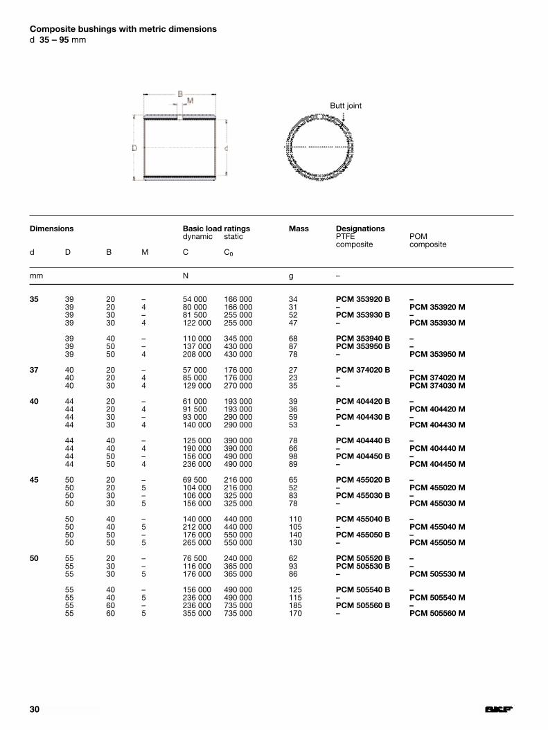
Composite bushings with metric dimensionsd 35 – 95 mm
Dimensions Basic load ratings Mass Designationsdynamic static PTFE POM
composite composited D B M C C0
mm N g –
35 39 20 – 54 000 166 000 34 PCM 353920 B –39 20 4 80 000 166 000 31 – PCM 353920 M39 30 – 81 500 255 000 52 PCM 353930 B –39 30 4 122 000 255 000 47 – PCM 353930 M
39 40 – 110 000 345 000 68 PCM 353940 B –39 50 – 137 000 430 000 87 PCM 353950 B –39 50 4 208 000 430 000 78 – PCM 353950 M
37 40 20 – 57 000 176 000 27 PCM 374020 B –40 20 4 85 000 176 000 23 – PCM 374020 M40 30 4 129 000 270 000 35 – PCM 374030 M
40 44 20 – 61 000 193 000 39 PCM 404420 B –44 20 4 91 500 193 000 36 – PCM 404420 M44 30 – 93 000 290 000 59 PCM 404430 B –44 30 4 140 000 290 000 53 – PCM 404430 M
44 40 – 125 000 390 000 78 PCM 404440 B –44 40 4 190 000 390 000 66 – PCM 404440 M44 50 – 156 000 490 000 98 PCM 404450 B –44 50 4 236 000 490 000 89 – PCM 404450 M
45 50 20 – 69 500 216 000 65 PCM 455020 B –50 20 5 104 000 216 000 52 – PCM 455020 M50 30 – 106 000 325 000 83 PCM 455030 B –50 30 5 156 000 325 000 78 – PCM 455030 M
50 40 – 140 000 440 000 110 PCM 455040 B –50 40 5 212 000 440 000 105 – PCM 455040 M50 50 – 176 000 550 000 140 PCM 455050 B –50 50 5 265 000 550 000 130 – PCM 455050 M
50 55 20 – 76 500 240 000 62 PCM 505520 B –55 30 – 116 000 365 000 93 PCM 505530 B –55 30 5 176 000 365 000 86 – PCM 505530 M
55 40 – 156 000 490 000 125 PCM 505540 B –55 40 5 236 000 490 000 115 – PCM 505540 M55 60 – 236 000 735 000 185 PCM 505560 B –55 60 5 355 000 735 000 170 – PCM 505560 M
Butt joint
31
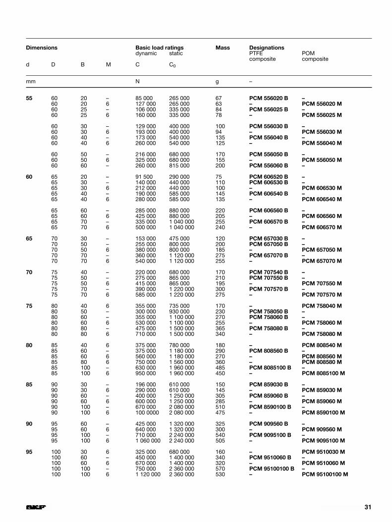
Dimensions Basic load ratings Mass Designationsdynamic static PTFE POM
composite composited D B M C C0
mm N g –
55 60 20 – 85 000 265 000 67 PCM 556020 B –60 20 6 127 000 265 000 63 – PCM 556020 M60 25 – 106 000 335 000 84 PCM 556025 B –60 25 6 160 000 335 000 78 – PCM 556025 M
60 30 – 129 000 400 000 100 PCM 556030 B –60 30 6 193 000 400 000 94 – PCM 556030 M60 40 – 173 000 540 000 135 PCM 556040 B –60 40 6 260 000 540 000 125 – PCM 556040 M
60 50 – 216 000 680 000 170 PCM 556050 B –60 50 6 325 000 680 000 155 – PCM 556050 M60 60 – 260 000 815 000 200 PCM 556060 B –
60 65 20 – 91 500 290 000 75 PCM 606520 B –65 30 – 140 000 440 000 110 PCM 606530 B –65 30 6 212 000 440 000 100 – PCM 606530 M65 40 – 190 000 585 000 145 PCM 606540 B –65 40 6 280 000 585 000 135 – PCM 606540 M
65 60 – 285 000 880 000 220 PCM 606560 B –65 60 6 425 000 880 000 205 – PCM 606560 M65 70 – 335 000 1 040 000 255 PCM 606570 B –65 70 6 500 000 1 040 000 240 – PCM 606570 M
65 70 30 – 153 000 475 000 120 PCM 657030 B –70 50 – 255 000 800 000 200 PCM 657050 B –70 50 6 380 000 800 000 185 – PCM 657050 M70 70 – 360 000 1 120 000 275 PCM 657070 B –70 70 6 540 000 1 120 000 255 – PCM 657070 M
70 75 40 – 220 000 680 000 170 PCM 707540 B –75 50 – 275 000 865 000 210 PCM 707550 B –75 50 6 415 000 865 000 195 – PCM 707550 M75 70 – 390 000 1 220 000 300 PCM 707570 B –75 70 6 585 000 1 220 000 275 – PCM 707570 M
75 80 40 6 355 000 735 000 170 – PCM 758040 M80 50 – 300 000 930 000 230 PCM 758050 B –80 60 – 355 000 1 100 000 270 PCM 758060 B –80 60 6 530 000 1 100 000 255 – PCM 758060 M80 80 – 475 000 1 500 000 365 PCM 758080 B –80 80 6 710 000 1 500 000 340 – PCM 758080 M
80 85 40 6 375 000 780 000 180 – PCM 808540 M85 60 – 375 000 1 180 000 290 PCM 808560 B –85 60 6 560 000 1 180 000 270 – PCM 808560 M85 80 6 750 000 1 560 000 360 – PCM 808580 M85 100 – 630 000 1 960 000 485 PCM 8085100 B –85 100 6 950 000 1 960 000 450 – PCM 8085100 M
85 90 30 – 196 000 610 000 150 PCM 859030 B –90 30 6 290 000 610 000 145 – PCM 859030 M90 60 – 400 000 1 250 000 305 PCM 859060 B –90 60 6 600 000 1 250 000 285 – PCM 859060 M90 100 – 670 000 2 080 000 510 PCM 8590100 B –90 100 6 100 0000 2 080 000 475 – PCM 8590100 M
90 95 60 – 425 000 1 320 000 325 PCM 909560 B –95 60 6 640 000 1 320 000 300 – PCM 909560 M95 100 – 710 000 2 240 000 540 PCM 9095100 B –95 100 6 1 060 000 2 240 000 505 – PCM 9095100 M
95 100 30 6 325 000 680 000 160 – PCM 9510030 M100 60 – 450 000 1 400 000 340 PCM 9510060 B –100 60 6 670 000 1 400 000 320 – PCM 9510060 M100 100 – 750 000 2 360 000 570 PCM 95100100 B –100 100 6 1 120 000 2 360 000 530 – PCM 95100100 M
32
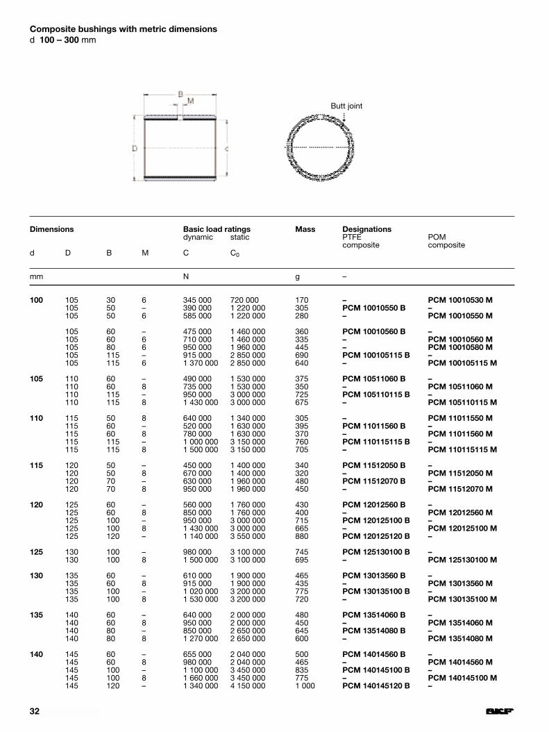
Composite bushings with metric dimensionsd 100 – 300 mm
Dimensions Basic load ratings Mass Designationsdynamic static PTFE POM
composite composited D B M C C0
mm N g –
100 105 30 6 345 000 720 000 170 – PCM 10010530 M105 50 – 390 000 1 220 000 305 PCM 10010550 B –105 50 6 585 000 1 220 000 280 – PCM 10010550 M
105 60 – 475 000 1 460 000 360 PCM 10010560 B –105 60 6 710 000 1 460 000 335 – PCM 10010560 M105 80 6 950 000 1 960 000 445 – PCM 10010580 M105 115 – 915 000 2 850 000 690 PCM 100105115 B –105 115 6 1 370 000 2 850 000 640 – PCM 100105115 M
105 110 60 – 490 000 1 530 000 375 PCM 10511060 B –110 60 8 735 000 1 530 000 350 – PCM 10511060 M110 115 – 950 000 3 000 000 725 PCM 105110115 B –110 115 8 1 430 000 3 000 000 675 – PCM 105110115 M
110 115 50 8 640 000 1 340 000 305 – PCM 11011550 M115 60 – 520 000 1 630 000 395 PCM 11011560 B –115 60 8 780 000 1 630 000 370 – PCM 11011560 M115 115 – 1 000 000 3 150 000 760 PCM 110115115 B –115 115 8 1 500 000 3 150 000 705 – PCM 110115115 M
115 120 50 – 450 000 1 400 000 340 PCM 11512050 B –120 50 8 670 000 1 400 000 320 – PCM 11512050 M120 70 – 630 000 1 960 000 480 PCM 11512070 B –120 70 8 950 000 1 960 000 450 – PCM 11512070 M
120 125 60 – 560 000 1 760 000 430 PCM 12012560 B –125 60 8 850 000 1 760 000 400 – PCM 12012560 M125 100 – 950 000 3 000 000 715 PCM 120125100 B –125 100 8 1 430 000 3 000 000 665 – PCM 120125100 M125 120 – 1 140 000 3 550 000 880 PCM 120125120 B –
125 130 100 – 980 000 3 100 000 745 PCM 125130100 B –130 100 8 1 500 000 3 100 000 695 – PCM 125130100 M
130 135 60 – 610 000 1 900 000 465 PCM 13013560 B –135 60 8 915 000 1 900 000 435 – PCM 13013560 M135 100 – 1 020 000 3 200 000 775 PCM 130135100 B –135 100 8 1 530 000 3 200 000 720 – PCM 130135100 M
135 140 60 – 640 000 2 000 000 480 PCM 13514060 B –140 60 8 950 000 2 000 000 450 – PCM 13514060 M140 80 – 850 000 2 650 000 645 PCM 13514080 B –140 80 8 1 270 000 2 650 000 600 – PCM 13514080 M
140 145 60 – 655 000 2 040 000 500 PCM 14014560 B –145 60 8 980 000 2 040 000 465 – PCM 14014560 M145 100 – 1 100 000 3 450 000 835 PCM 140145100 B –145 100 8 1 660 000 3 450 000 775 – PCM 140145100 M145 120 – 1 340 000 4 150 000 1 000 PCM 140145120 B –
Butt joint

33
Dimensions Basic load ratings Mass Designationsdynamic static PTFE POM
composite composited D B M C C0
mm N g –
150 155 60 – 710 000 2 200 000 535 PCM 15015560 B –155 60 8 1 060 000 2 200 000 500 – PCM 15015560 M155 80 – 950 000 3 000 000 715 PCM 15015580 B –155 80 8 1 430 000 3 000 000 665 – PCM 15015580 M155 100 – 1 200 000 3 750 000 890 PCM 150155100 B –155 100 8 1 800 000 3 750 000 830 – PCM 150155100 M
160 165 80 – 1 000 000 3 150 000 780 PCM 16016580 B –165 80 8 1 500 000 3 150 000 710 – PCM 16016580 M165 100 – 1 270 000 3 900 000 970 PCM 160165100 B –165 100 8 1 900 000 3 900 000 885 – PCM 160165100 M
180 185 80 – 1 140 000 3 550 000 870 PCM 18018580 B –185 80 8 1 700 000 3 550 000 795 – PCM 18018580 M185 100 – 1 430 000 4 400 000 1 100 PCM 180185100 B –185 100 8 2 120 000 4 400 000 995 – PCM 180185100 M
190 195 60 8 1 340 000 2 800 000 630 – PCM 19019560 M195 100 8 2 240 000 4 650 000 1 050 – PCM 190195100 M
200 205 100 – 1 600 000 4 900 000 1 200 PCM 200205100 B –205 100 8 2 360 000 4 900 000 1 100 – PCM 200205100 M
210 215 100 – 1 660 000 5 200 000 1 250 PCM 210215100 B –215 100 8 2 500 000 5 200 000 1 150 – PCM 210215100 M
220 225 100 – 1 730 000 5 400 000 1 350 PCM 220225100 B –225 100 8 2 600 000 5 400 000 1 200 – PCM 220225100 M
250 255 100 – 1 960 000 6 100 000 1 500 PCM 250255100 B –255 100 8 3 000 000 6 100 000 1 400 – PCM 250255100 M
280 285 80 – 1 760 000 5 500 000 1 350 PCM 28028580 B –285 80 8 2 650 000 5 500 000 1 250 – PCM 28028580 M
300 305 50 – 1 180 000 3 650 000 900 PCM 30030550 B –305 50 8 1 760 000 3 650 000 825 – PCM 30030550 M305 100 – 2 360 000 7 350 000 1 800 PCM 300305100 B –305 100 8 3 550 000 7 350 000 1 650 – PCM 300305100 M

Dimensions Basic load ratings Mass Designationsdynamic static PTFE POM
composite composited D B M C C0
inch mm inch mm inch mm mm N g –
0,125 3,175 0,1875 4,763 0,125 3,175 – 800 2 500 0,23 PCZ 0202 B –0,1875 4,763 – 1 200 3 750 0,34 PCZ 0203 B –
0,1562 3,969 0,2188 5,556 0,1562 3,969 – 1 270 3 900 0,34 PCZ 025025 B –0,25 6,35 – 2 000 6 300 0,54 PCZ 02504 B –
0,1875 4,763 0,25 6,35 0,1875 4,763 – 1 800 5 700 0,48 PCZ 0303 B –0,25 6,35 – 2 400 7 500 0,63 PCZ 0304 B –0,375 9,525 – 3 650 11 400 0,95 PCZ 0306 B –
0,25 6,35 0,3125 7,938 0,25 6,35 – 3 250 10 000 0,81 PCZ 0404 B –0,375 9,525 – 4 800 15 000 1,2 PCZ 0406 B –
0,3125 7,938 0,375 9,525 0,375 9,525 – 6 000 19 000 1,5 PCZ 0506 B –0,5 12,7 – 8 000 25 000 2,0 PCZ 0508 B –
0,375 9,525 0,4687 11,906 0,375 9,525 – 7 200 22 800 2,8 PCZ 0606 B –0,375 9,525 – 10 800 22 800 2,3 – PCZ 0606 M0,5 12,7 – 9 800 30 000 3,8 PCZ 0608 B –0,5 12,7 – 11 400 30 000 3,0 – PCZ 0608 M0,75 19,05 – 14 600 45 500 5,8 PCZ 0612 B –0,75 19,05 – 21 600 45 500 4,6 – PCZ 0612 M
0,4375 11,113 0,5312 13,494 0,5 12,7 – 11 200 35 500 4,3 PCZ 0708 B0,5 12,7 3 17 000 35 500 3,5 – PCZ 0708 M0,75 19,05 – 17 000 53 000 6,5 PCZ 0712 B –0,75 19,05 3 25 500 53 000 5,2 – PCZ 0712 M
0,5 12,7 0,5937 15,081 0,375 9,525 – 9 800 30 000 3,7 PCZ 0806 B –0,375 9,525 3 14 600 30 000 3,0 – PCZ 0806 M0,5 12,7 – 12 900 40 500 4,9 PCZ 0808 B –0,5 12,7 3 19 300 40 500 3,9 – PCZ 0808 M0,625 15,875 – 16 000 50 000 6,1 PCZ 0810 B –0,625 15,875 3 24 000 50 000 4,9 – PCZ 0810 M0,875 22,225 – 22 400 71 000 8,5 PCZ 0814 B –0,875 22,225 3 33 400 71 000 6,9 – PCZ 0814 M
0,5625 14,288 0,6562 16,669 0,5 12,7 – 14 600 45 500 5,4 PCZ 0908 B –0,5 12,7 3 21 600 45 500 4,4 – PCZ 0908 M0,75 19,05 – 21 600 68 000 8,2 PCZ 0912 B –0,75 19,05 3 32 500 68 000 6,6 – PCZ 0912 M
0,625 15,875 0,7187 18,256 0,5 12,7 – 16 000 50 000 6,0 PCZ 1008 B –0,5 12,7 3 24 000 50 000 4,9 – PCZ 1008 M0,625 15,875 – 20 000 63 000 7,5 PCZ 1010 B –0,625 15,875 3 30 000 63 000 6,1 – PCZ 1010 M0,75 19,05 – 24 000 75 000 9,0 PCZ 1012 B –0,75 19,05 3 36 000 75 000 7,3 – PCZ 1012 M0,875 22,225 – 28 000 88 000 10,5 PCZ 1014 B –0,875 22,225 3 42 500 88 000 8,5 – PCZ 1014 M
34
Composite bushings with inch dimensionsd 0,125 – 1,75 inch
Butt joint
35
Dimensions Basic load ratings Mass Designationsdynamic static PTFE POM
composite composited D B M C C0
inch mm inch mm inch mm mm N g –
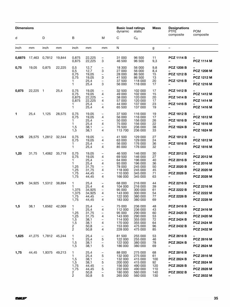
0,6875 17,463 0,7812 19,844 0,875 22,225 – 31 000 96 500 11 PCZ 1114 B –0,875 22,225 3 46 500 96 500 9,3 – PCZ 1114 M
0,75 19,05 0,875 22,225 0,5 12,7 – 18 300 56 000 9,8 PCZ 1208 B –0,5 12,7 3 27 000 56 000 8,4 – PCZ 1208 M0,75 19,05 – 28 000 86 500 15 PCZ 1212 B –0,75 19,05 3 41 500 86 500 13 – PCZ 1212 M1 25,4 – 37 500 118 000 20 PCZ 1216 B –1 25,4 3 56 000 118 000 17 – PCZ 1216 M
0,875 22,225 1 25,4 0,75 19,05 – 32 500 102 000 17 PCZ 1412 B –0,75 19,05 4 49 000 102 000 15 – PCZ 1412 M0,875 22,225 – 38 000 120 000 20 PCZ 1414 B –0,875 22,225 4 57 000 120 000 17 – PCZ 1414 M1 25,4 – 44 000 137 000 23 PCZ 1416 B –1 25,4 4 65 500 137 000 19 – PCZ 1416 M
1 25,4 1,125 28,575 0,75 19,05 – 37 500 116 000 19 PCZ 1612 B –0,75 19,05 4 56 000 116 000 17 – PCZ 1612 M1 25,4 – 50 000 156 000 26 PCZ 1616 B –1 25,4 4 75 000 156 000 22 – PCZ 1616 M1,5 38,1 – 76 500 236 000 38 PCZ 1624 B –1,5 38,1 4 113 700 236 000 33 – PCZ 1624 M
1,125 28,575 1,2812 32,544 0,75 19,05 – 41 500 129 000 27 PCZ 1812 B –0,75 19,05 4 63 000 129 000 24 – PCZ 1812 M1 25,4 – 56 000 176 000 36 PCZ 1816 B –1 25,4 4 85 000 176 000 32 – PCZ 1816 M
1,25 31,75 1,4062 35,719 0,75 19,05 – 46 500 146 000 30 PCZ 2012 B –0,75 19,05 4 69 500 146 000 27 – PCZ 2012 M1 25,4 – 64 000 196 000 40 PCZ 2016 B –1 25,4 4 93 000 196 000 36 – PCZ 2016 M1,25 31,75 – 78 000 245 000 50 PCZ 2020 B –1,25 31,75 4 118 000 245 000 45 – PCZ 2020 M1,75 44,45 – 110 000 345 000 71 PCZ 2028 B –1,75 44,45 4 166 000 345 000 63 – PCZ 2028 M
1,375 34,925 1,5312 38,894 1 25,4 – 68 000 216 000 44 PCZ 2216 B –1 25,4 4 104 000 216 000 39 – PCZ 2216 M1,375 34,925 – 95 000 300 000 61 PCZ 2222 B –1,375 34,925 4 143 000 300 000 54 – PCZ 2222 M1,75 44,45 – 122 000 380 000 77 PCZ 2228 B –1,75 44,45 4 183 000 380 000 69 – PCZ 2228 M
1,5 38,1 1,6562 42,069 1 25,4 – 75 000 236 000 48 PCZ 2416 B –1 25,4 4 112 000 236 000 43 – PCZ 2416 M1,25 31,75 – 95 000 290 000 60 PCZ 2420 B –1,25 31,75 4 143 000 290 000 53 – PCZ 2420 M1,5 38,1 – 114 000 355 000 72 PCZ 2424 B –1,5 38,1 4 170 000 355 000 64 – PCZ 2424 M2 50,8 – 153 000 475 000 96 PCZ 2432 B –2 50,8 4 228 000 475 000 85 – PCZ 2432 M
1,625 41,275 1,7812 45,244 1 25,4 – 81 500 255 000 53 PCZ 2616 B –1 25,4 5 122 000 255 000 46 – PCZ 2616 M1,5 38,1 – 122 000 380 000 78 PCZ 2624 B –1,5 38,1 5 186 000 380 000 69 – PCZ 2624 M
1,75 44,45 1,9375 49,213 1 25,4 – 88 000 275 000 68 PCZ 2816 B –1 25,4 5 132 000 275 000 61 – PCZ 2816 M1,5 38,1 – 132 000 415 000 100 PCZ 2824 B –1,5 38,1 5 200 000 415 000 92 – PCZ 2824 M1,75 44,45 – 156 000 490 000 120 PCZ 2828 B –1,75 44,45 5 232 000 490 000 110 – PCZ 2828 M2 50,8 – 180 000 560 000 140 PCZ 2832 B –2 50,8 5 265 000 560 000 130 – PCZ 2832 M
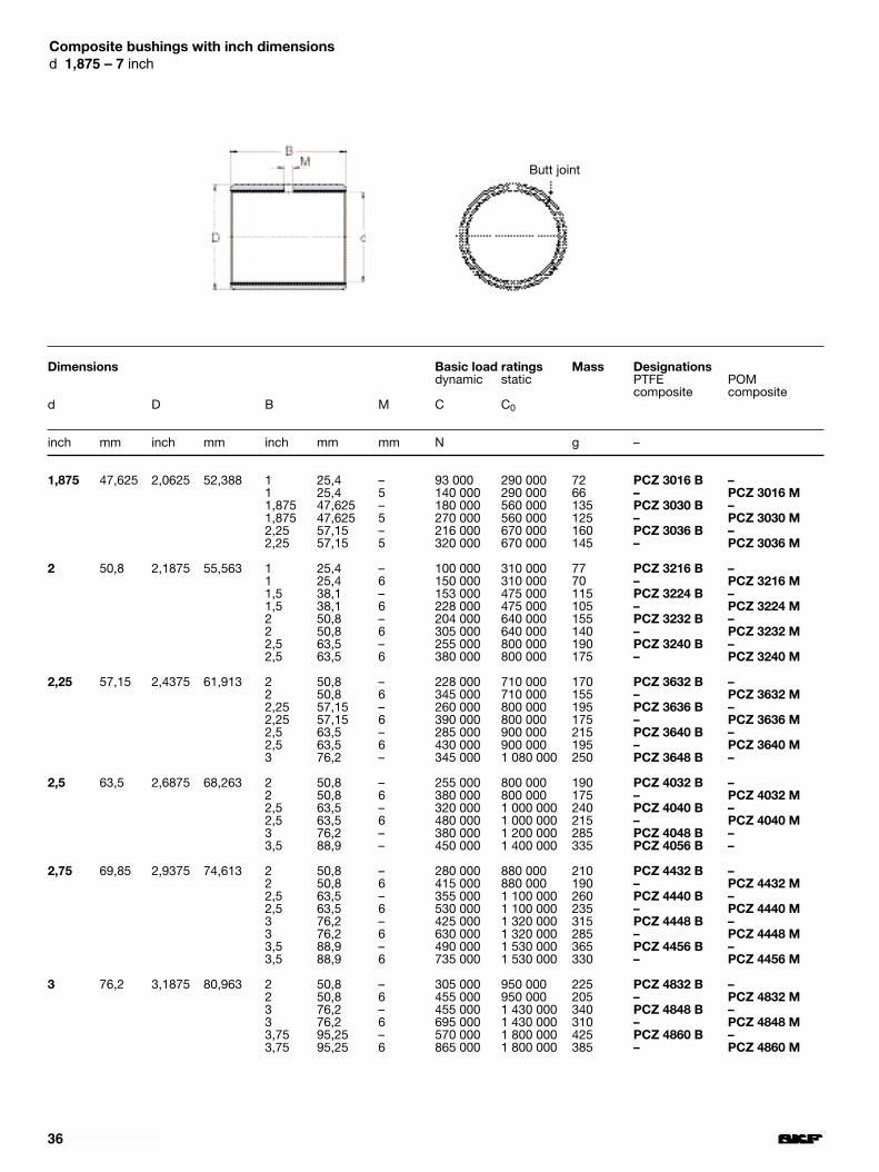
Dimensions Basic load ratings Mass Designationsdynamic static PTFE POM
composite composited D B M C C0
inch mm inch mm inch mm mm N g –
1,875 47,625 2,0625 52,388 1 25,4 – 93 000 290 000 72 PCZ 3016 B –1 25,4 5 140 000 290 000 66 – PCZ 3016 M1,875 47,625 – 180 000 560 000 135 PCZ 3030 B –1,875 47,625 5 270 000 560 000 125 – PCZ 3030 M2,25 57,15 – 216 000 670 000 160 PCZ 3036 B –2,25 57,15 5 320 000 670 000 145 – PCZ 3036 M
2 50,8 2,1875 55,563 1 25,4 – 100 000 310 000 77 PCZ 3216 B –1 25,4 6 150 000 310 000 70 – PCZ 3216 M1,5 38,1 – 153 000 475 000 115 PCZ 3224 B –1,5 38,1 6 228 000 475 000 105 – PCZ 3224 M2 50,8 – 204 000 640 000 155 PCZ 3232 B –2 50,8 6 305 000 640 000 140 – PCZ 3232 M2,5 63,5 – 255 000 800 000 190 PCZ 3240 B –2,5 63,5 6 380 000 800 000 175 – PCZ 3240 M
2,25 57,15 2,4375 61,913 2 50,8 – 228 000 710 000 170 PCZ 3632 B –2 50,8 6 345 000 710 000 155 – PCZ 3632 M2,25 57,15 – 260 000 800 000 195 PCZ 3636 B –2,25 57,15 6 390 000 800 000 175 – PCZ 3636 M2,5 63,5 – 285 000 900 000 215 PCZ 3640 B –2,5 63,5 6 430 000 900 000 195 – PCZ 3640 M3 76,2 – 345 000 1 080 000 250 PCZ 3648 B –
2,5 63,5 2,6875 68,263 2 50,8 – 255 000 800 000 190 PCZ 4032 B –2 50,8 6 380 000 800 000 175 – PCZ 4032 M2,5 63,5 – 320 000 1 000 000 240 PCZ 4040 B –2,5 63,5 6 480 000 1 000 000 215 – PCZ 4040 M3 76,2 – 380 000 1 200 000 285 PCZ 4048 B –3,5 88,9 – 450 000 1 400 000 335 PCZ 4056 B –
2,75 69,85 2,9375 74,613 2 50,8 – 280 000 880 000 210 PCZ 4432 B –2 50,8 6 415 000 880 000 190 – PCZ 4432 M2,5 63,5 – 355 000 1 100 000 260 PCZ 4440 B –2,5 63,5 6 530 000 1 100 000 235 – PCZ 4440 M3 76,2 – 425 000 1 320 000 315 PCZ 4448 B –3 76,2 6 630 000 1 320 000 285 – PCZ 4448 M3,5 88,9 – 490 000 1 530 000 365 PCZ 4456 B –3,5 88,9 6 735 000 1 530 000 330 – PCZ 4456 M
3 76,2 3,1875 80,963 2 50,8 – 305 000 950 000 225 PCZ 4832 B –2 50,8 6 455 000 950 000 205 – PCZ 4832 M3 76,2 – 455 000 1 430 000 340 PCZ 4848 B –3 76,2 6 695 000 1 430 000 310 – PCZ 4848 M3,75 95,25 – 570 000 1 800 000 425 PCZ 4860 B –3,75 95,25 6 865 000 1 800 000 385 – PCZ 4860 M
36
Composite bushings with inch dimensionsd 1,875 – 7 inch
Butt joint
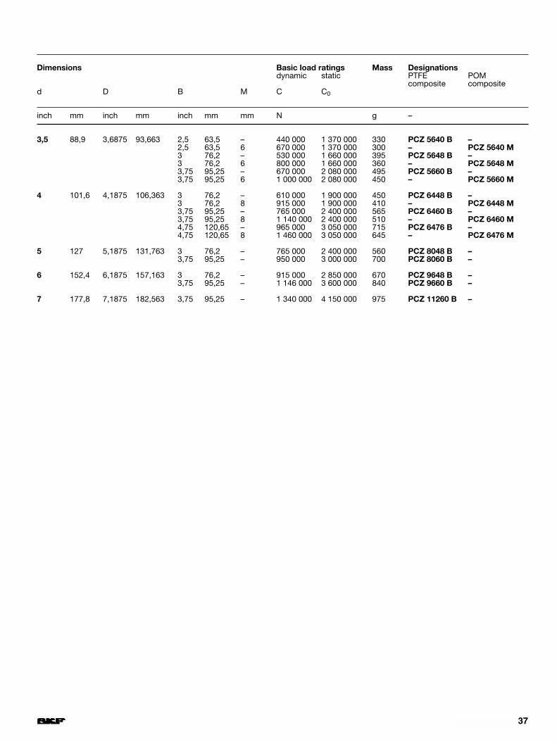
37
Dimensions Basic load ratings Mass Designationsdynamic static PTFE POM
composite composited D B M C C0
inch mm inch mm inch mm mm N g –
3,5 88,9 3,6875 93,663 2,5 63,5 – 440 000 1 370 000 330 PCZ 5640 B –2,5 63,5 6 670 000 1 370 000 300 – PCZ 5640 M3 76,2 – 530 000 1 660 000 395 PCZ 5648 B –3 76,2 6 800 000 1 660 000 360 – PCZ 5648 M3,75 95,25 – 670 000 2 080 000 495 PCZ 5660 B –3,75 95,25 6 1 000 000 2 080 000 450 – PCZ 5660 M
4 101,6 4,1875 106,363 3 76,2 – 610 000 1 900 000 450 PCZ 6448 B –3 76,2 8 915 000 1 900 000 410 – PCZ 6448 M3,75 95,25 – 765 000 2 400 000 565 PCZ 6460 B –3,75 95,25 8 1 140 000 2 400 000 510 – PCZ 6460 M4,75 120,65 – 965 000 3 050 000 715 PCZ 6476 B –4,75 120,65 8 1 460 000 3 050 000 645 – PCZ 6476 M
5 127 5,1875 131,763 3 76,2 – 765 000 2 400 000 560 PCZ 8048 B –3,75 95,25 – 950 000 3 000 000 700 PCZ 8060 B –
6 152,4 6,1875 157,163 3 76,2 – 915 000 2 850 000 670 PCZ 9648 B –3,75 95,25 – 1 146 000 3 600 000 840 PCZ 9660 B –
7 177,8 7,1875 182,563 3,75 95,25 – 1 340 000 4 150 000 975 PCZ 11260 B –
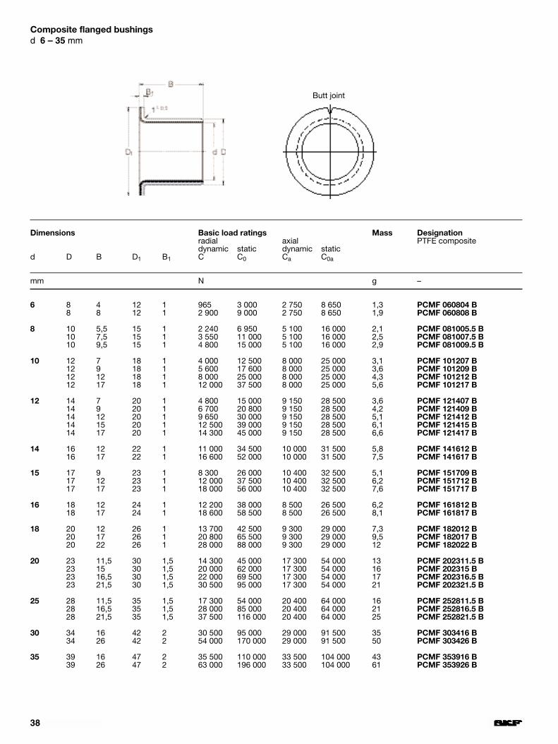
38
Dimensions Basic load ratings Mass Designationradial axial PTFE compositedynamic static dynamic static
d D B D1 B1 C C0 Ca C0a
mm N g –
6 8 4 12 1 965 3 000 2 750 8 650 1,3 PCMF 060804 B8 8 12 1 2 900 9 000 2 750 8 650 1,9 PCMF 060808 B
8 10 5,5 15 1 2 240 6 950 5 100 16 000 2,1 PCMF 081005.5 B10 7,5 15 1 3 550 11 000 5 100 16 000 2,5 PCMF 081007.5 B10 9,5 15 1 4 800 15 000 5 100 16 000 2,9 PCMF 081009.5 B
10 12 7 18 1 4 000 12 500 8 000 25 000 3,1 PCMF 101207 B12 9 18 1 5 600 17 600 8 000 25 000 3,6 PCMF 101209 B12 12 18 1 8 000 25 000 8 000 25 000 4,3 PCMF 101212 B12 17 18 1 12 000 37 500 8 000 25 000 5,6 PCMF 101217 B
12 14 7 20 1 4 800 15 000 9 150 28 500 3,6 PCMF 121407 B14 9 20 1 6 700 20 800 9 150 28 500 4,2 PCMF 121409 B14 12 20 1 9 650 30 000 9 150 28 500 5,1 PCMF 121412 B14 15 20 1 12 500 39 000 9 150 28 500 6,1 PCMF 121415 B14 17 20 1 14 300 45 000 9 150 28 500 6,6 PCMF 121417 B
14 16 12 22 1 11 000 34 500 10 000 31 500 5,8 PCMF 141612 B16 17 22 1 16 600 52 000 10 000 31 500 7,5 PCMF 141617 B
15 17 9 23 1 8 300 26 000 10 400 32 500 5,1 PCMF 151709 B17 12 23 1 12 000 37 500 10 400 32 500 6,2 PCMF 151712 B17 17 23 1 18 000 56 000 10 400 32 500 7,6 PCMF 151717 B
16 18 12 24 1 12 200 38 000 8 500 26 500 6,2 PCMF 161812 B18 17 24 1 18 600 58 500 8 500 26 500 8,1 PCMF 161817 B
18 20 12 26 1 13 700 42 500 9 300 29 000 7,3 PCMF 182012 B20 17 26 1 20 800 65 500 9 300 29 000 9,5 PCMF 182017 B20 22 26 1 28 000 88 000 9 300 29 000 12 PCMF 182022 B
20 23 11,5 30 1,5 14 300 45 000 17 300 54 000 13 PCMF 202311.5 B23 15 30 1,5 20 000 62 000 17 300 54 000 16 PCMF 202315 B23 16,5 30 1,5 22 000 69 500 17 300 54 000 17 PCMF 202316.5 B23 21,5 30 1,5 30 500 95 000 17 300 54 000 21 PCMF 202321.5 B
25 28 11,5 35 1,5 17 300 54 000 20 400 64 000 16 PCMF 252811.5 B28 16,5 35 1,5 28 000 85 000 20 400 64 000 21 PCMF 252816.5 B28 21,5 35 1,5 37 500 116 000 20 400 64 000 25 PCMF 252821.5 B
30 34 16 42 2 30 500 95 000 29 000 91 500 35 PCMF 303416 B34 26 42 2 54 000 170 000 29 000 91 500 50 PCMF 303426 B
35 39 16 47 2 35 500 110 000 33 500 104 000 43 PCMF 353916 B39 26 47 2 63 000 196 000 33 500 104 000 61 PCMF 353926 B
Composite flanged bushingsd 6 – 35 mm
Butt joint
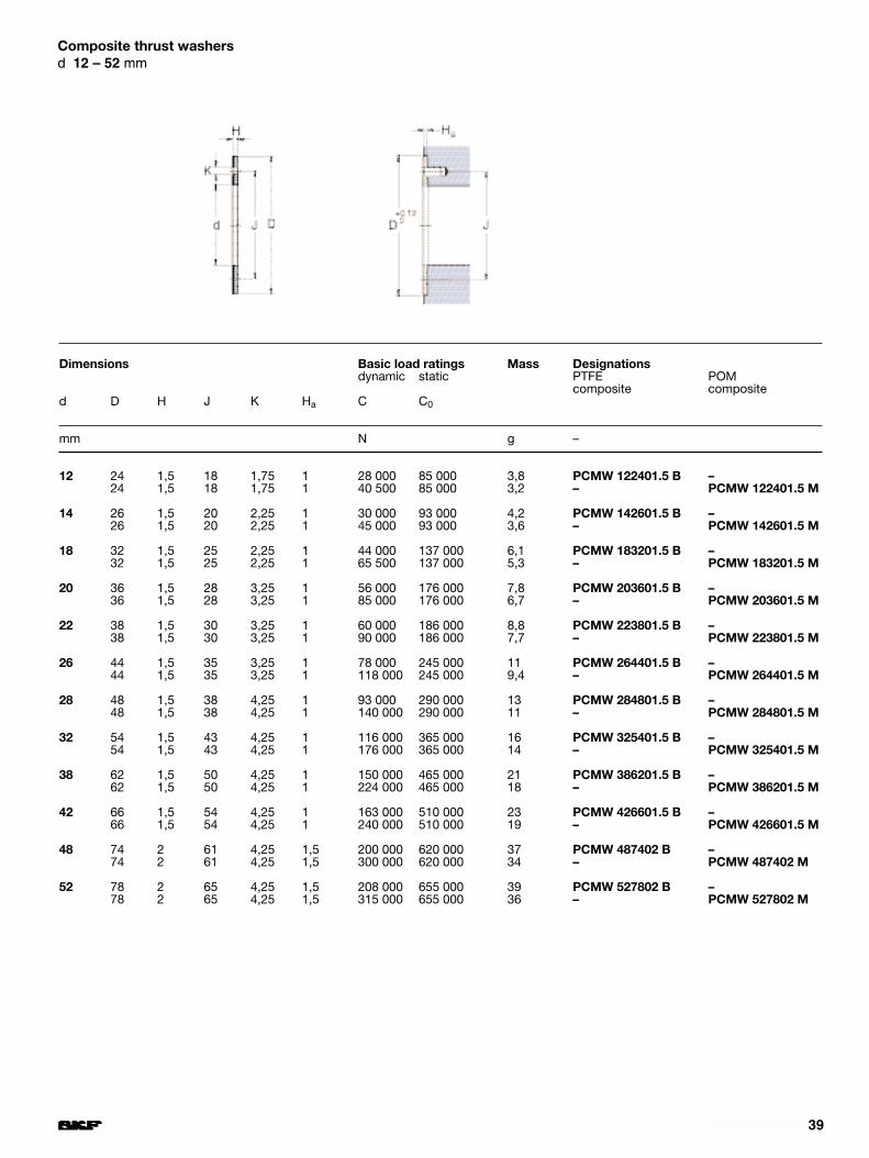
39
Dimensions Basic load ratings Mass Designationsdynamic static PTFE POM
composite composited D H J K Ha C C0
mm N g –
12 24 1,5 18 1,75 1 28 000 85 000 3,8 PCMW 122401.5 B –24 1,5 18 1,75 1 40 500 85 000 3,2 – PCMW 122401.5 M
14 26 1,5 20 2,25 1 30 000 93 000 4,2 PCMW 142601.5 B –26 1,5 20 2,25 1 45 000 93 000 3,6 – PCMW 142601.5 M
18 32 1,5 25 2,25 1 44 000 137 000 6,1 PCMW 183201.5 B –32 1,5 25 2,25 1 65 500 137 000 5,3 – PCMW 183201.5 M
20 36 1,5 28 3,25 1 56 000 176 000 7,8 PCMW 203601.5 B –36 1,5 28 3,25 1 85 000 176 000 6,7 – PCMW 203601.5 M
22 38 1,5 30 3,25 1 60 000 186 000 8,8 PCMW 223801.5 B –38 1,5 30 3,25 1 90 000 186 000 7,7 – PCMW 223801.5 M
26 44 1,5 35 3,25 1 78 000 245 000 11 PCMW 264401.5 B –44 1,5 35 3,25 1 118 000 245 000 9,4 – PCMW 264401.5 M
28 48 1,5 38 4,25 1 93 000 290 000 13 PCMW 284801.5 B –48 1,5 38 4,25 1 140 000 290 000 11 – PCMW 284801.5 M
32 54 1,5 43 4,25 1 116 000 365 000 16 PCMW 325401.5 B –54 1,5 43 4,25 1 176 000 365 000 14 – PCMW 325401.5 M
38 62 1,5 50 4,25 1 150 000 465 000 21 PCMW 386201.5 B –62 1,5 50 4,25 1 224 000 465 000 18 – PCMW 386201.5 M
42 66 1,5 54 4,25 1 163 000 510 000 23 PCMW 426601.5 B –66 1,5 54 4,25 1 240 000 510 000 19 – PCMW 426601.5 M
48 74 2 61 4,25 1,5 200 000 620 000 37 PCMW 487402 B –74 2 61 4,25 1,5 300 000 620 000 34 – PCMW 487402 M
52 78 2 65 4,25 1,5 208 000 655 000 39 PCMW 527802 B –78 2 65 4,25 1,5 315 000 655 000 36 – PCMW 527802 M
Composite thrust washersd 12 – 52 mm

40
Composite strip
Dimensions Mass DesignationsPTFE POMcomposite composite
B L H
mm kg –
100 500 1,0 0,35 PCMS 1005001.0 B –500 1,0 0,28 – PCMS 1005001.0 M
100 500 1,5 0,55 PCMS 1005001.5 B –500 1,5 0,46 – PCMS 1005001.5 M
100 500 2,0 0,75 PCMS 1005002.0 B –500 2,0 0,65 – PCMS 1005002.0 M
100 500 2,5 0,55 PCMS 1005002.5 B –500 2,5 0,85 – PCMS 1005002.5 M
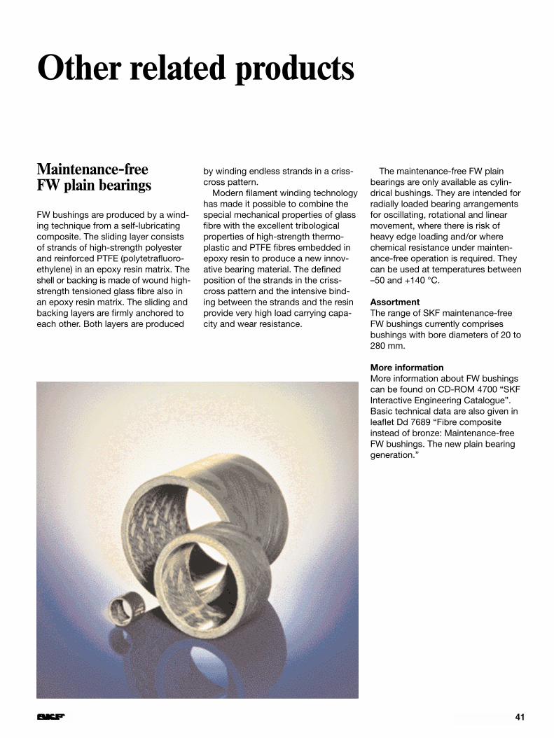
41
Maintenance-free FW plain bearings
FW bushings are produced by a wind-ing technique from a self-lubricatingcomposite. The sliding layer consistsof strands of high-strength polyesterand reinforced PTFE (polytetrafluoro-ethylene) in an epoxy resin matrix. Theshell or backing is made of wound high-strength tensioned glass fibre also inan epoxy resin matrix. The sliding andbacking layers are firmly anchored toeach other. Both layers are produced
Other related products
by winding endless strands in a criss-cross pattern.
Modern filament winding technologyhas made it possible to combine thespecial mechanical properties of glassfibre with the excellent tribologicalproperties of high-strength thermo-plastic and PTFE fibres embedded inepoxy resin to produce a new innov-ative bearing material. The definedposition of the strands in the criss-cross pattern and the intensive bind-ing between the strands and the resinprovide very high load carrying capa-city and wear resistance.
The maintenance-free FW plainbearings are only available as cylin-drical bushings. They are intended forradially loaded bearing arrangementsfor oscillating, rotational and linearmovement, where there is risk ofheavy edge loading and/or wherechemical resistance under mainten-ance-free operation is required. Theycan be used at temperatures between–50 and +140 °C.
AssortmentThe range of SKF maintenance-freeFW bushings currently comprisesbushings with bore diameters of 20 to280 mm.
More informationMore information about FW bushingscan be found on CD-ROM 4700 “SKFInteractive Engineering Catalogue”.Basic technical data are also given inleaflet Dd 7689 “Fibre compositeinstead of bronze: Maintenance-freeFW bushings. The new plain bearinggeneration.”

12
42
Fig
Other related products
SKF spherical plainbearings
For arrangements where alignmentmovements have to be accommod-ated between two components in relat-ive motion or where tilting movementsor oscillations occur at relatively lowsliding velocities, normally only spher-ical plain bearings are suitable. Theyhave an inner ring with a sphered con-vex outside surface and an outer ringwith a correspondingly sphered butconcave inside surface. Whereverspherical plain bearings are needed,whether maintenance can be providedor not, SKF spherical plain bearingswill meet the bill.
The bearings requiring maintenancehave the sliding contact surface com-bination steel-on-steel. As a rule,bearings with this sliding contact sur-face combination require regular relub-rication. The high wear resistance of
the sliding surfaces makes these bear-ings especially suitable for arrange-ments where heavy loads of alternatingdirection, shock loads or heavy staticloads have to be accommodated.
The SKF maintenance-free sphericalplain bearings incorporate special slid-ing layers of advanced materials whichhave very low friction. They are usedfor applications where long bearinglives are required without mainten-ance, or where operating conditionslike inadequate or total absence oflubrication do not allow the use ofsteel-on-steel bearings. SKF mainten-ance-free bearings are produced withthree different sliding contact surfacecombinations, depending on bearingsize and series. These three slidingcontact surface combinations are
• steel/sinter bronze composite,• steel/PTFE fabric, and• steel/PTFE composite.
AssortmentThe comprehensive SKF assortmentcomprises radial, angular contact andthrust bearings and covers a journaldiameter range between 4 and 1 250mm.
Further informationFor detailed information about SKFspherical plain bearings please refer toCD-ROM 4700 “SKF InteractiveEngineering Catalogue” or brochure4407 “SKF spherical plain bearingsand rod ends”.
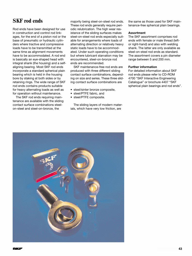
43
SKF rod endsRod ends have been designed for usein construction and control rod link-ages, for the end of a piston rod or thebase of pneumatic or hydraulic cylin-ders where tractive and compressiveloads have to be transmitted at thesame time as alignment movementshave to be accommodated. A rod endis basically an eye-shaped head withintegral shank (the housing) and a self-aligning bearing. Most SKF rod endsincorporate a standard spherical plainbearing which is held in the housingbore by staking at both sides or byretaining rings. The wide range of SKFrod ends contains products suitablefor heavy alternating loads as well asfor operation without maintenance.
The SKF rod ends requiring main-tenance are available with the slidingcontact surface combinations steel-on-steel and steel-on-bronze, the
majority being steel-on-steel rod ends.These rod ends generally require peri-odic relubrication. The high wear res-istance of the sliding surfaces makessteel-on-steel rod ends especially suit-able for arrangements where loads ofalternating direction or relatively heavystatic loads have to be accommod-ated. Under such operating conditionsbut where lubricant starvation may beencountered, steel-on-bronze rodends are recommended.
SKF maintenance-free rod ends areproduced with three different slidingcontact surface combinations, depend-ing on size and series. These three slid-ing contact surface combinations are
• steel/sinter bronze composite,• steel/PTFE fabric, and• steel/PTFE composite.
The sliding layers of modern mater-ials, which have very low friction, are
the same as those used for SKF main-tenance-free spherical plain bearings.
AssortmentThe SKF assortment comprises rodends with female or male thread (left-or right-hand) and also with weldingshank. The latter are only available assteel-on-steel rod ends as standard.The assortment covers a pin diameterrange between 5 and 200 mm.
Further informationFor detailed information about SKFrod ends please refer to CD-ROM4700 “SKF Interactive EngineeringCatalogue” or brochure 4407 “SKFspherical plain bearings and rod ends”.

44
Application examples
The unique properties and excellentperformance of dry sliding bearingshave led to their use in a variety ofindustrial, domestic and other applica-tions. They are particularly suitable forconditions where both maintenanceand lubrication are either not requiredor not possible. Examples of typicalexisting applications for these bear-ings are as follows.
AutomotiveKing pins, starter pinions, brake rodlinkages, brake shafts, brake shoes,suspensions, window lifts, foot pedals,accelerator linkages, fans, propellershafts, clutch release levers, steeringrods, steering columns, swingingarms, shock absorbers, carburettorbutterfly valves etc.
Rail vehicles, railway installationsAutomatic doors, level crossing bar-riers, brakes, pantographs, controllers,load switches, relay boxes, signallingequipment, wagons, points etc.
AerospaceBrakes, electronic equipment, under-carriages, engines, radar equipment,control devices etc.
Construction industry, conveyingequipmentLifts, excavator drives, excavator arms,excavator control equipment, concretemixers, fork lift trucks, hydraulic rams,chain tensioning sprockets, cranedrives, crane control equipment, cranejibs, mortar carriers, pallet lift trucks,pneumatic lifts, caterpillar graders,escalators, moving pavements, vibrat-ing screens, slides, shuttering cleaning
machines, low loader trailers, winches,conveyors of all kinds etc.
Office machines and equipmentAddressing machines, data processingequipment, tape recorders, swivellingchairs, franking machines, copiers,blueprint copiers, drawing tables,drawing machines etc.
Domestic appliances, hospitalequipmentDental equipment, dishwashers, iron-ing machines, air conditioning equip-ment, hospital beds, refrigerators,sewing machines, operating tables, X-ray equipment, vacuum cleaners,washing machines etc.
Machines for agriculture and food-stuff industriesBottling machines, bakery equipment,timber saws, filtering centrifuges,abattoir and meat processing equip-ment, hay tedders, potato harvesters,wine-making equipment, loaders,unloaders, combine harvesters, mills,planting machines, root crop har-vesters, balers, tractors, tractor seats,automatic packaging equipment,weighing equipment etc.
General engineeringChamfering machines, bendingmachines, machines for sheet metalworking, briquetting machines, forgemachinery, woodworking machines,plastic moulding machines, presses,automatic welding equipment,machine tools, crushing plant etc.
Papermaking and textilesCutting machines, printing machines,doubling machines, folding machines,yarn and wool machines, vulcanisingmachines, carders, button machines,papermaking and paper-treatingmachinery, sorting devices, spinningmachines, stuffers, knitting machines,looms etc.
Pumps, valvesAxial and radial piston pumps, meter-ing pumps, firefighting pumps, com-pressors, ball cocks, mixer valves, oilburners, pumps for chemicals, regulat-ing valves, submersible pumps, va-cuum pumps, spur gear pumps etc.
Electrical equipmentStarting levers for electric motors,contactors, control equipment, switchgear etc.
Automatic devices, toolsCharging and feeding devices, vend-ing machines, pneumatic tools,hydraulic tools etc.
Other usesRefuse disposal equipment and plant,brake magnets, heat treatment plant,blinds, awnings, smelting furnaces,continuously variable gears, dryingplant, steel construction etc.

45
Linear guide for a car suspension strutpiston rod with a PTFE composite bushing
Bearing arrangement for a sunshade(awning) linkage with flanged PTFEcomposite bushings
Bearing arrangement for the leaf springattachment to the upper linkage of abogie with PTFE composite bushings
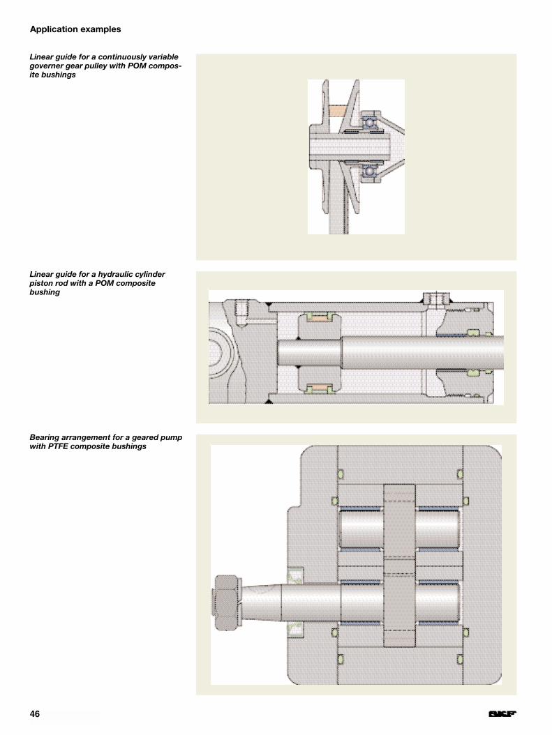
46
Linear guide for a continuously variablegoverner gear pulley with POM compos-ite bushings
Linear guide for a hydraulic cylinder piston rod with a POM composite bushing
Bearing arrangement for a geared pumpwith PTFE composite bushings
Application examples

47
Bearing arrange-ment for a heavyloader trailersteering gear shiftlever with POMcomposite bush-ings
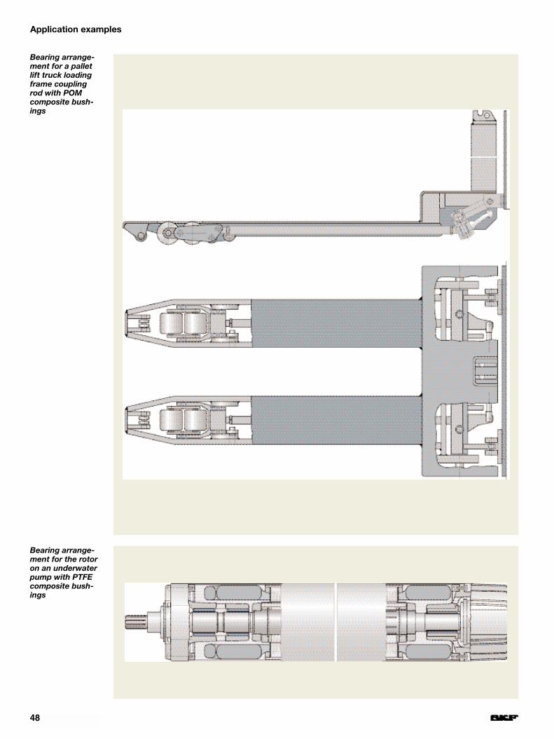
48
Bearing arrange-ment for a palletlift truck loadingframe couplingrod with POMcomposite bush-ings
Bearing arrange-ment for the rotoron an underwaterpump with PTFEcomposite bush-ings
Application examples

49
Coupling rod bearing arrangements fora printing press gear lever with PTFEcomposite bushings
Bearing arrangement for a conveyorroller with a PTFE composite bushing
Bearing arrangement for the cutter ondebarking equipment with flanged PTFEcomposite bushings
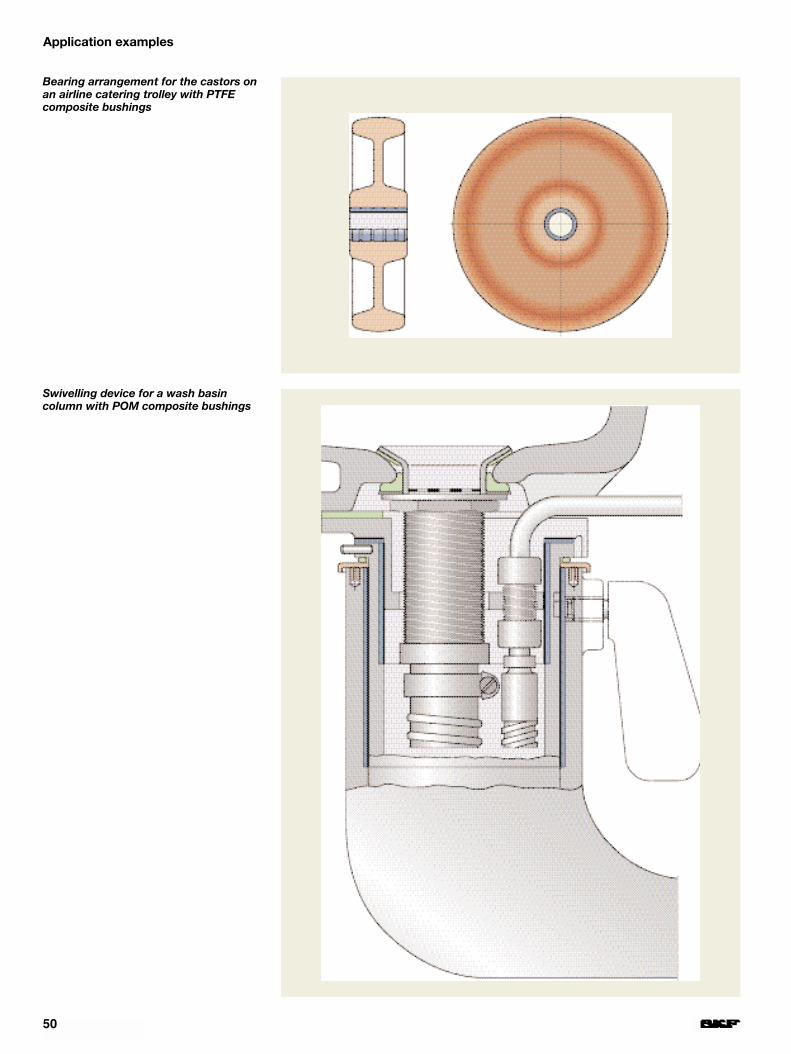
50
Bearing arrangement for the castors onan airline catering trolley with PTFEcomposite bushings
Swivelling device for a wash basin column with POM composite bushings
Application examples

51
Bearing arrangement for the platformand side rollers of a platform conveyorwith POM composite bushings
King pin bearing arrangement with POMcomposite bushings

52
Linear guide for a truck servo steeringwith PTFE composite bushings
Bearing arrangement for a lift-off axlewith POM composite bushings andthrust washers
Application examples

53

54
The SKF group – a worldwide corporation
SKF is an international industrial Groupoperating in some 130 countries and isworld leader in bearings.
The company was founded in 1907following the invention of the self-align-ing ball bearing by Sven Wingquist and,after only a few years, SKF began toexpand all over the world.
Today, SKF has some 45 000 em-ployees and around 80 manufacturingfacilities spread throughout the world.An international sales network includesa large number of sales companies andsome 7 000 distributors and retailers.Worldwide availability of SKF productsis supported by a comprehensive technical advisory service.
The key to success has been a con-sistent emphasis on maintaining thehighest quality of its products and services. Continuous invest-ment in research and
development has also played a vitalrole, resulting in many examples ofepoch-making innovations.
The business of the Group consistsof bearings, seals, special steel and acomprehensive range of other high-tech industrial components. The experi-ence gained in these various fieldsprovides SKF with the essential know-ledge and expertise required in orderto provide the customers with the mostadvanced engineering products andefficient service.
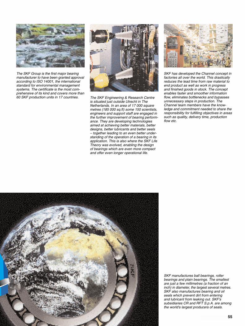
55
The SKF Group is the first major bearingmanufacturer to have been granted approvalaccording to ISO 14001, the internationalstandard for environmental managementsystems. The certificate is the most com-prehensive of its kind and covers more than60 SKF production units in 17 countries. The SKF Engineering & Research Centre
is situated just outside Utrecht in TheNetherlands. In an area of 17 000 squaremetres (185 000 sq.ft) some 150 scientists,engineers and support staff are engaged inthe further improvement of bearing perform-ance. They are developing technologiesaimed at achieving better materials, betterdesigns, better lubricants and better seals – together leading to an even better under-standing of the operation of a bearing in itsapplication. This is also where the SKF LifeTheory was evolved, enabling the design of bearings which are even more compactand offer even longer operational life.
SKF has developed the Channel concept infactories all over the world. This drasticallyreduces the lead time from raw material toend product as well as work in progress and finished goods in stock. The conceptenables faster and smoother informationflow, eliminates bottlenecks and bypassesunnecessary steps in production. TheChannel team members have the know-ledge and commitment needed to share theresponsibility for fulfilling objectives in areassuch as quality, delivery time, productionflow etc.
SKF manufactures ball bearings, roller bearings and plain bearings. The smallestare just a few millimetres (a fraction of aninch) in diameter, the largest several metres.SKF also manufactures bearing and oilseals which prevent dirt from entering and lubricant from leaking out. SKF's subsidiaries CR and RFT S.p.A. are amongthe world's largest producers of seals.

© Copyright SKF 1999The contents of this publication are thecopyright of the publisher and may not be reproduced (even extracts) unlesspermission is granted. Every care hasbeen taken to ensure the accuracy ofthe information contained in this publica-tion but no liability can be accepted for any loss or damage whether direct,indirect or consequential arising out ofthe use of the information containedherein.
Publication 4413 E
Printed in Sweden on environmentallyfriendly, chlorine-free paper (Multiart Silk)by SG idé & tryck ab.


![Advanced Composite Materials in Cryogenic Propellant Tank · 2019-12-26 · m) in height [9, 10]. Fig 2.1.3a Sandwich construction and Fig 2.1.3b LH2 cryo-tank [9, 10] 4) Northrop](https://img.dokumen.tips/doc/110x75/5ecc1d03d33b5279e8267d4f/advanced-composite-materials-in-cryogenic-propellant-tank-2019-12-26-m-in-height.jpg)


