Embed Size (px)
Citation preview


B.A.E. HAWK www.carf-models.com
2
Thank you very much for purchasing our Composite-ARF ‘Hawk’ jet, made with therevolutionary Total Area Vacuum Sandwich (TAVS) technology.
Before you get started building and setting-up your aircraft, please make sure you have readthis instruction manual, and understood it. If you have any questions, please don’t hesitate tocontact your Rep, or C-ARF directly. Below are the contact details:
Email: [email protected]
Telephone: Phone your C-ARF Rep!!! He will be there for you.
Website: http://www.carf-models.com
LLiiaabbiilliittyy EExxcclluussiioonn aanndd DDaammaaggeess
You have acquired a kit, which can be assembled into a fully working R/C model when fitted out
with suitable accessories, as described in the instruction manual with the kit.
However, as manufacturers, we at Composite-ARF are not in a position to influence the way youbuild and operate your model, and we have no control over the methods you use to install,operate and maintain the radio control system components. For this reason we are obliged todeny all liability for loss, damage or costs which are incurred due to the incompetent orincorrect application and operation of our products, or which are connected with such operationin any way. Unless otherwise prescribed by binding law, the obligation of the Composite-ARFcompany to pay compensation is excluded, regardless of the legal argument employed. Thisapplies to personal injury, death, damage to buildings, loss of turnover and business,interruption of business or other direct and indirect consequent damages. In all circumstances
our total liability is limited to the amount which you actually paid for this model.
BY OPERATING THIS MODEL YOU ASSUME FULL RESPONSIBILITY FOR YOUR ACTIONS.
It is important to understand that Composite-ARF Co., Ltd, is unable to monitor whether youfollow the instructions contained in this instruction manual regarding the construction, operationand maintenance of the aircraft, nor whether you install and use the radio control systemcorrectly. For this reason we at Composite-ARF are unable to guarantee, or provide, acontractual agreement with any individual or company that the model you have made willfunction correctly and safely. You, as operator of the model, must rely upon your own expertiseand judgement in acquiring and operating this model.

B.A.E. HAWK www.carf-models.com
3
Attention !
This ‘jet’ aircraft is a high-end product and can create an enormous risk for both pilot and spectators,
if not handled with care & used according to the instructions. Make sure that you operate your ‘Hawk’according to the laws and regulations governing model flying in the country of use. The engine, landinggear, servos, linkages and control surfaces have to be attached properly. Please use only therecommended servos and accessories. Make sure that the ‘Centre of Gravity’ is located in therecommended place. Use the nose heavy end of the CG range for your first flights. A tail heavy planecan be an enormous danger for you and all spectators. Fix any weights, and heavy items like batteries,very securely into the plane. Make sure that the plane is secured properly when you start the engine.Have a helper hold your plane from the nose before you start the engine. Make sure that all spectatorsare far behind, or far in front, of the aircraft when running up the engine. Make sure that you rangecheck your R/C system thoroughly before the 1st flight. It is absolutely necessary to range check yourcomplete R/C installation first WITHOUT the engine running. Leave the transmitter antenna retracted, andcheck the distance you can walk before ‘fail-safe’ occurs. Then start the engine, run at about half throttleand repeat this range check. Make sure that there is no range reduction before ‘fail-safe’ occurs. If therange with engine running is less then with the engine off, please DON’T FLY at that time. Check that thewing and stab retaining bolts are tight, and that all linkages are secured. Please don’t ignore ourwarnings, or those provided by other manufacturers. They refer to things and processes which, if ignored,could result in permanent damage or fatal injury.
Important/General Notes
Elastic Hinges:
The ailerons, elevator, flaps and rudder are all hinged for you. The ailerons and flaps are laminated in themould and attached with a special nylon hinge-cloth, sandwiched between the outer skin and the foam.This nylon hinge is 100% safe and durable. You will never have to worry about breaking it, or wearing itout. There is no gap at all on the top side of the surface, and there is a very narrow slot in the bottomsurface, where the control surface slides under the skin during ‘down’ throw. This means that the hingeaxis line is on the top surface of the wing and stab, not in the centre. This is NOT a disadvantage, but youneed to program in about 10% NEGATIVE differential in your transmitter. This means that the ‘down’throw needs to be about 10% more than the ‘up’ throw. Why? Because the axis of the hinge is not at thecentreline of the aileron/elevator, so it moves slightly in and out when operated, and the control surfacegets a little "smaller" in surface area when moving downwards. The slot needs some explanation, too. Thecut line is exactly in the correct position so that the control surface slides under the wing skin smoothly. Ifthe cut was a few mm forward or backwards, it would not work properly. So, make sure that the lip is notdamaged, and that the control surface slides under this lip perfectly. It will not lock at any time, as long asthe lip is not damaged. If damage occurs, you can cut a maximum of 2-3 mm off the lip on the wing infront of the control surface, but you should never cut off more than this.The rudder is hinged with a metalrod passing through factory fitted hinge plates. The all flying elevator hinges on a large carbon platefitted with ball-races, which pivots on a carbon tube that requires locking in position.
Servo Choice:We strongly advise that you use the recommended servos and equipment listed in the manual.
Servo Screws:Fix the all the servos into the milled plywood servo mounts using the 2.9 Ø x13mm or 16mm sheet metalscrews provided in the kit, not the standard screws normally supplied with servos by the servo manufac-turer. This is because all the holes in our milled servo mounts are 2mm diameter, due to our CNC manu-facturing process, and this is too big for the normal screws
Building Sequence:The actual building sequence is your choice, but it is definitely most efficient to start at the back of thefuselage and work forwards, in the same order as shown below.

4
Take Care:Composite sandwich parts are extremely strong, but fragile at the same time. Always keep in mind thatthese contest airplanes are designed for minimum weight and maximum strength in flight. Please take careof it, especially during transport, to make sure that none of the critical parts and linkages are damaged.Always handle your airplane with great care, especially on the ground and during transport, so you willhave many hours of pleasure with it. To protect the finished paint on the outside of the model fromscratches and dents during building, cover your work table with a piece of soft carpet, cloth or bubble-plastic. The best way to stop small spots of glue getting stuck to the outside painted surfaces is to give thewhole model 2 good coats of clear car wax first, but of course you must be sure to remove this 100%properly before adding any additional paint, markings or trim.
Adhesives and SolventsNot all types of glues are suited to working with composite parts. Here is a selection of what we normallyuse, and what we can truly recommend. Please don’t use inferior quality glues - you will end up with aninferior quality plane, that is not so strong or safe. Jet models require good gluing techniques, due to thehigher flying speeds, and hence higher loads on many of the joints. We highly recommend that you use aslow filled thixotropic epoxy for gluing highly stressed joints (eg: Hysol 9462). The self-mixing nozzlesmake it easy to apply exactly the required amount, in exactly the right place, and it will not run or flowonto places where you don’t want it! It takes about 1 - 2 hours to start to harden so it also gives plenty oftime for accurate assembly. Finally it gives a superb bond on all fibreglass and wood surfaces. Of coursethere are many similar glues available, and you can use your favourite type.
1. CA glue ‘Thin’ and ‘Thick’ types. We recommend ZAP, as this is very high quality.2. ZAP-O or Plasti-ZAP, odourless, or ZAP canopy glue 560 (for clear canopy)3. 30 minute epoxy (stressed joints must be glued with at least 30 min & NOT 5 min epoxy).4. Loctite Hysol 9462 or equivalent (optional, but highly recommended)5. Epoxy laminating resin (12 - 24 hr cure) with hardener.6. Milled glass fibre, for adding to slow epoxy for stronger joints.7. Micro-balloons, for adding to slow epoxy for lightweight filling.8. Thread-locking compound (Loctite 243, ZAP Z-42, or equivalent)
We take great care during production at the factory to ensure that all joints are properly glued, but ofcourse it is wise to check these yourself and re-glue any that might just have been missed. When sandingareas on the inside of the composite sandwich parts to prepare the surface for gluing something onto it,do NOT sand through the layer of lightweight glasscloth on the inside foam sandwich. It is only necessaryto rough up the surface, with 80/120 grit, and wipe off any dust with acetone or de-natured alcohol (orsimilar) before gluing to make a perfect joint. Of course, you should always prepare both parts to bejoined before gluing for the highest quality joints. Don’t use Acetone for cleaning external, painted, sur-faces as you will damage the paint. Tip: For cleaning small (uncured) glue spots or marks off the paintedsurfaces you can use old-fashioned liquid cigarette-lighter fuel, like ‘Ronsonol’ or equivalent. This does notdamage the paint, as Acetone and many other solvents will, and this is what we use at the factory. AtComposite-ARF we try our best to offer you a high quality kit, with outstanding value-for-money, and ascomplete as possible. However, if you feel that some additional or different hardware should be included,please feel free to let us know. Email us: [email protected]. We know that even good thingscan be made better !
Did you read the hints and warnings above and the instructions carefully?Did you understand everything in this manual completely?Then, and only then, let’s start assembling your Composite-ARF HawkIf not, please read it again before you continue.
B.A.E. HAWK www.carf-models.com

www.carf-models.com
5
This list will help you chose the main additional items needed to finish your CompositeARF BAE Hawk.
Some of the recommendations are mandatory and some can be sourced and chosen byyou. The items we list here are highly recommended by C-ARF, and have been tested onvarious prototype aircraft used during the development of this aeroplane.
1. Servos (minimum 8 high quality servos) All the main control surfaces require aminimum 11kg digital servo (two matched servos for the elevator control) such asthe Gr/JR 8411/8711 metal geared servos. All the prototype Hawk models usedJR 8711 servos.
2. Heavy duty servo arms are recommended, for the JR servos we used JR partJRPA215 or Graupner #Nr 3544. Two packets required.
3. A receiver power supply system like the excellent Powerbox units arerecommended using two separate batteries through separate regulators. The Hawkrequires some weight in the nose area, so the additional batteries all help.
4. Turbine set. Turbines in the 10-16kg (20-36lb) thrust range have been used in theprototype aeroplanes. Turbines in the 16kg (36lb) 160N thrust class should beseen as the maximum thrust for the aeroplane and should not be exceeded. Ideallya 160N turbine should be turned down in RPM 5%. Comp ARF display aeroplanesuse JetCat turbines.
5. Retractable Landing Gear sets are available from Composite-ARF in sport andscale sets (C-ARF product #200500-Sport) and (#200600-Scale). The Hawk wasdesigned specifically around the German manufactured AT high quality sets thatinclude three units, plus specifically manufactured trailing link legs with associatedball raced wheels and high quality brake units. If you chose the sports scale gearto start with you can upgrade at a later date using scale upgrade set (C-ARFproduct #200650)
6. Landing Gear support equipment is available from Composite-ARF (#200550), orcan be sourced by you. The Hawk requires a minimum of three air rams to operatethe gear doors (four with a scale nose gear door set up). The retract valve chosenneeds to operate air up/down units and a suitable method of controlling the geardoor opening sequence. The Hawk has the gear doors stay open when the landinggear is in the down position. C-ARF set features high quality parts including airvalves from Jet Tronic to control the gear and door opening, plus brakes. Suitableair tubing and a large capacity air tank for landing gear/door operation. Fillervalves and quick disconnect joiners. We strongly recommend you use this provenhigh quality set.
ACCESSORIES

B.A.E. HAWK www.carf-models.com
7. A radio system with a minimum of 7 channels is needed, but C-ARF recommend aquality system with 9 or more channels to allow individual servo connections to thereceiver system (talk to your C-ARF rep for advice on a suitable system) Highquality extension leads are required and a guide to the sizes and quantitiesrequired are listed below.
8. The Hawk features a large cockpit area which benefits from some additionaldetail. Our Hawk is a perfect starting point for a scale aeroplane, addingadditional cockpit detail using products like the 1:5 scale ejector seats fromGraupner and canopy glass MDC from Taylor Made Decals will add to thealready impressive look of this iconic aeroplane.
6

www.carf-models.com
Thrust Tube Assembly
The thrust tube is manufactured from an aluminiumouter “cool” tube and a stainless steel inner piperolled and spot welded for you at the factory.
This tube is designed to work with the sizes of turbineintended for the BAE Hawk. Turbines in the 22-35lbthrust class are perfect.
The tail pipe is mounted in the fuselage between therear fuselage cut-out opening and aluminiummounting brackets provided that fix to the carbonbellmouth and turbine mounting rails.
The first job is to fix the carbon bellmouth to thestainless inner tube. The bellmouth is designed to goinside the tail pipe and be fixed by M3 cap headscrews or pop rivets if available to you.
The thrust tube can be fitted in any orientation, butthe neatest look is with the joint seam at the topwhen the aeroplane is on its wheels.
For simplicity the Hawk was designed without fullducting, hundreds of test flights in various conditionshave shown perfect operation and normal turbinetemperatures.
A trial fit of the carbon bellmouth should show anyareas that need sanding to allow a snug fit. Thecarbon moulding process will undoubtedly lead to avariation in thickness of the material. Some early tailtubes show a reduction in diameter where the lip isformed in the tail pipe tube, this needs to be workedout before the carbon bellmouth will fit. Later pipeshave no lip.
Once the bellmouth can be inserted at least 12mmdrill four holes to suit the fixing you have chosen.
If using M3 x 8 Socket head cap screws use washersunder the screw heads on the inside (carbon)
Fitting the aluminium mounting angles to the bellmouth at approximately 3 and 9o’clock is best done after the turbine has been mounted so that the inner tube is fixedcentrally on the turbine cone. This is important to avoid “hot Spots” in the pipe that canlead to tube failures. Note that on early kits the tail pipe outer “cool” tube will get veryclose to the elevator servo mounting plate restricting how high the pipe can be mountedat the front. Later kits will have more clearance.
Alignment by eye is accurate enough when fitting the carbon cone.
The outer tube should protrude through the fuselage rear between 3 and 5mm. This sets
7
CONSTRUCTION
Fig 1
Fig 2
Fig 3
B.A.E. HAWK www.carf-models.com
the position.
Access to the two front mounting screws (2.2 x 10mm) is improved if you drill two accessholes in the rear wing seating area. Holes drilled at 170mm centres approx and 10mmin from the rear edge of the wing. The tail pipe front brackets should be screwed directlyto the turbine mounting rails. Be sure to centralise the carbon bell mouth between therails as the deflector duct fits outside of the carbon bell mouth.
Turbine Installation
Mounting the turbine is very straight forward on the Hawk, with excellent access to theturbine through the wing opening. Mount the turbine directly on the bearers, higherpower turbines benefit from being mounted slightly higher in the fuselage. To achievethis the motor mount could be fixed below the rails (when looking through the wingopening)
Modern electric start turbines remove the need forengine access hatches, as the operator does not needto attach or detach anything from the turbine duringstarting.
We recommend a turbine of 12-16kg thrust, the threeprototype aeroplanes have been flown with JetCatP120SX and P160SX turbines.
Any turbine between 22 and 35lb thrust will giveadequate performance to the Hawk. For lessexperienced pilots we recommend turbines over 35lbthrust have the maximum RPM reduced to limit output.
IMPORTANT SAFETY INFORMATION. The Hawk isdesigned for a maximum turbine thrust of 16kg-Thismust not be exceeded. All installation pictures show aJetCat P120SX, , which give more than scaleperformance including huge vertical elements.
Many of the turbines available now feature off-setmounts. The exact position of the turbine will affect thethrust tubes vertical position, which can affect theHawk’s trim. On very early kits the elevator servoplate is mounted 10mm lower in the fuselage,requiring a small dent placing in the outer cool tube toallow clearance for the correct bellmouth height. Onthe prototype model 8mm of packing was required.
The exact position of the turbine fore and aft willdepend on your chosen turbine. With the JetCatturbines we recommend a distance of 25mm betweenthe back of the turbines tail cone and the carbonbellmouth/stainless tube joint. This relates to the front
8
Fig 6
Fig 5
Fig 4

B.A.E. HAWK www.carf-models.com
of the turbine purple cover finishing just in front of thewing fixing formers.
The carbon turbine deflector guard mounts to thecarbon bellmouth with three M3 x 10 Allen bolts,washers and nuts. The guard features mounting earsthat sit between the turbine mounting lugs.
When you drill the fixing holes for your chosenturbine it is very important that the turbine is centredon the tail pipe tube. It is also important that theturbine is not angled so that the hot gasses are beingdirected onto the tail pipe walls. JetCat turbines areinstalled with the cable connection towards the top ofthe aeroplane, away from the wing. Drill the fourmounting holes ø4 one at a time, adding a screw intothe drilled holes in turn, help keep the turbineposition. Once drilled remove the turbine and openthe holes to ø5.5mm ready for the M4 T-nuts. Thesecan be pulled into position with the M4 Allen screwsand large spreader washers. The carbon deflectorguard may require a hole to accept the turbine cable,with the shown JetCat turbine a single hole isrequired for the power cable.
Fuel Tank Setup
Composite-ARF offer an optional moulded Kevlar fueltank of 4.1 ltr capacity, which is installed in thefuselage on the C of G and a plastic tank that can beused as a hopper tank in the cockpit area. If you wishto fit smoke some of the C-ARF team pilots have usedFlash wing tanks mounted below the main fuel tank. Ifthis set up is chosen the wing services should exit thewing through the leading edge/wing mount face,with corresponding holes drilled in both faces. Themain tank is moulded with a deeper rear trough toretain fuel towards the end of the tank.
Before starting assembly of the moulded tank it isimportant that any debris left in the tank during themanufacturing process is flushed out. Washing thetank with warm water and some washing detergentworks well. Ensure the tank is completely dry beforeyou assemble it fully.
The tank comes factory joined and is tested in thefactory for leaks. The recommended hardware isprovided in the kit. Care when assembling the fuel
9
Fig 7
Fig 8
Fig 9
Fig 10

B.A.E. HAWK www.carf-models.com
tank cap and tubing will reward you with a reliableaeroplane. De-bur inside the brass tubing with a newsharp scalpel blade and remove any raised edges onthe outside caused by cutting. To aid sealing and helpprevent the fuel tube coming off, solder the shortlengths of tube provided a few mm back from eachend of the feed line and on the outside of the breatherline only.
Use Tygone tube for the clunk line, where the clunklinepasses through the baffle insert a section of brass tubeas the glass fibre edge can easily cut through thetygone tube. The supplied soft clunk will becomeheavier when charged with fuel and easily reach allareas of the fuel tank.
The fuel tank is designed to be easily removable,retained by the aluminium tank cap at the front andtwo fixing brackets at the rear. The tank cap isinserted into a 60 x 60 3mm plywood plate that isfixed to former F2. The two aluminium angles and 30x 3 x 185mm plywood strip are bonded to the rear ofthe tank. Two M4 Allen screws fix these angles toplywood mounts bonded to the fuselage sides. Startby laminating the four 40 x 45mm 3mm plywoodmounts into two pairs.
Drill ø 4.1 holes centred on one each of the aluminiumangle faces. Drilling small holes in the opposite facewill help improve the bond to the Plywood spreaderplate and a small screw can be added for additionalsecurity. Assembly of the rear mount is simplified ifyou tack glue each part in position with a spot of SloZap cyanoacrylate glue. Start by fixing the plywoodcross piece to the rear of the tank. Gently lay thetank in the fuselage with the 60 x 3 x 60mm frontmount in plate to set the for/aft position of the tank.Even moulded Kevlar tanks expand slightly duringfilling, so it is important that the tank is not pusheddown into the fuselage before fixing. Tack glue the 40x 45 x 6mm side mounts to the fuselage side againstthe former F3 approximately 8mm down from thefuselage contour change, using a few spots of thickCA glue. Tack glue the aluminium mounting angle tothe plywood spreader plate with the ø 4.1mm holeagainst the plywood mounts. Using a pen, mark thefixing position on the 40 x 45 x 6mm plywood plates.Remove the tank and break free the angles. Mark the
10
Fig 11
Fig 12
Fig 13
Fig 14

B.A.E. HAWK www.carf-models.com
plywood spreader position on the rear face of the tank and sand the area ready forbonding. Break free the side mounts and drill the marked position ø5.1 to accept M4T-nuts. The T-nut face will require recessing slightly to allow the mounts to fit flush on thefuselage side. Bond the T-nuts in position with a small amount of CA or epoxy,squeezing the nuts fully home in a vice. Ensure you make a pair. Bond the plywoodspreader plate to the tank and allow it to dry.
Mix enough epoxy to fix the 40 x 45 side mounts and aluminium angles in position, puta small amount of grease on the M4 x 10 Allen head screws to stop them sticking to theT-nuts. Loosely screw the angles to the side mountsand place the tank in position locating the anglesagainst the spreader plate and the side mountsagainst the fuselage side and former. Tighten thescrews enough to hold everything in position whilethe glue sets.
Remove the tank and reinforce the mount asrequired.
Canopy Frame and Canopy Glass
The moulded canopy frame has been factory trimmedand the retaining system completed. The BAE Hawkfeatures a large canopy where the fixing and canopyrigidity is critical. A pair of canopy hooks at the rearand a single M4 cap head screw at the front holdsthe canopy in position with two location tabs halfwayalong the frame.
The fixing nut is factory installed and the frame testfitted before leaving the factory.
The Hawk canopy glass is quite large, this makesfitment a little harder.
It is important to sand the inside gluing surface toremove any high spots and it is worth looking alongthe frame edge to check for any areas that havebeen moulded thicker than ideal. Pay particularattention to the joint seam line where additional tapeis added. This should be thinned with a Dremmel typedrum sander before the clear glass is fitted.
To ensure the clear glass meets the canopy loop, thefront edge contact lip contact should be kept to aminimum.
To protect the clear glass, it is good practice to coverit completely with masking tape. This protects theglass while it is being trial fitted and makes it easier
11
Fig 15
Fig 16
Fig 17
B.A.E. HAWK www.carf-models.com
to mark cut lines on.
Trim the front and rear end plate areas off the clear glass with a pair of curved cuttingscissors.
Tip, do this when the canopy has been sitting in a warm room for some time.
Lay the canopy glass carefully over the canopy frame and mark the rough cut lines witha marker pen. Mark this line level with the lower edge of the canopy frame-this willensure a little excess is left.
Test fit the glass inside the canopy frame and note any areas that need further trimming.Small notches might be required around the canopy hooks and tabs.
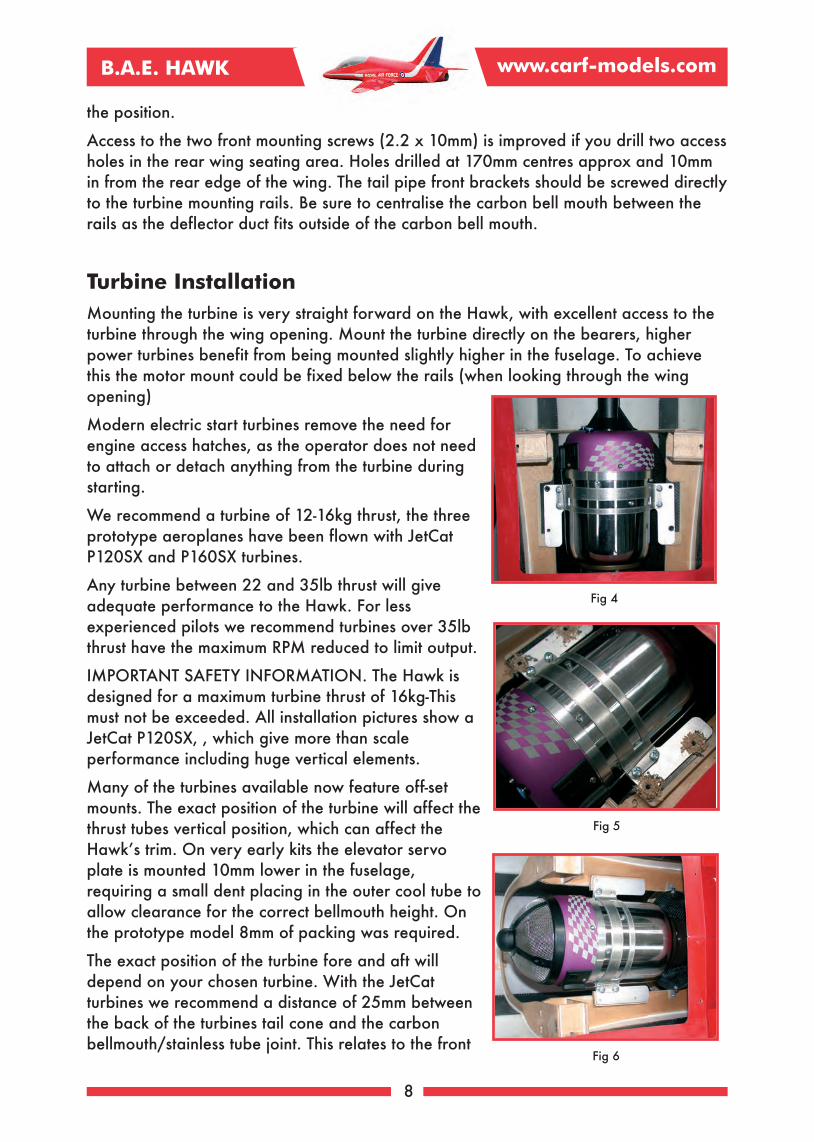
Many modellers have their own favourite method ofgluing the canopy glass in position. We have hadgood results with Zap 560 canopy glue and or ZapCA Note: Do not use kicker which generates excessheat and can cause the clear glass to fog.
The long sides on the Hawk frame are flat, this allowsthe use of straight edge packers to help clamp theclear glass against the frame. We cut a length ofscrap balsa to use inside the glass and charger powerclips to clamp the glass in position while the gluedried.
Tailplane Assembly
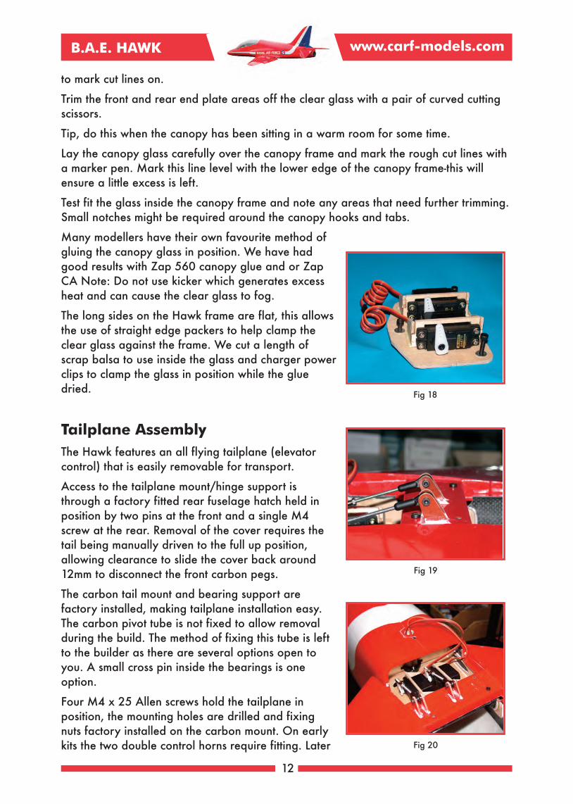
The Hawk features an all flying tailplane (elevatorcontrol) that is easily removable for transport.
Access to the tailplane mount/hinge support isthrough a factory fitted rear fuselage hatch held inposition by two pins at the front and a single M4screw at the rear. Removal of the cover requires thetail being manually driven to the full up position,allowing clearance to slide the cover back around12mm to disconnect the front carbon pegs.
The carbon tail mount and bearing support arefactory installed, making tailplane installation easy.The carbon pivot tube is not fixed to allow removalduring the build. The method of fixing this tube is leftto the builder as there are several options open toyou. A small cross pin inside the bearings is oneoption.
Four M4 x 25 Allen screws hold the tailplane inposition, the mounting holes are drilled and fixingnuts factory installed on the carbon mount. On earlykits the two double control horns require fitting. Later
12
Fig 19
Fig 18
Fig 20

B.A.E. HAWK www.carf-models.com
kits will have these factory installed.
Fitting the horns on the early kits is a straightforward job, requiring four slots cutting inthe top surface of the cross brace. This brace is hollow in the centre where the centrepair of horns fit and filled where the outer pair fit. The centre pair of horns shouldprotrude through to the lower skin. The outer pair should be inserted a minimum of10mm.
Mark the control horn centres, working from the left hand pair of mounting holes mark aline parallel to the two holes 8mm to the left. Then measure across and mark a secondline 51mm to the right. These lines match the pushrod line from the centrally positionedball ends. The control horns are fixed with an 8mm gap between. Mark 4mm either sideof the two lines you have made. Outside of these, mark two more lines allowing for thethickness of the horns-approx 2mm. You will slot between these two lines. The fore/aftposition is measured from the front edge of the cross brace, mark a line 17mm backfrom the front edge and a second line a further 17mm behind this. Slotting the brace iseasy using either chain drilled holes or a Dremel type cutter.
The control horn centres should be 16mm above the top surface of the brace and 18mmback from the front face, these figures are not as critical as the two sets of hornsmatching.
Two matching elevator servos are required. Composite ARF recommend the JR 8711servo for this important control. Careful matching of the two servos using your radio ora servo tester is imperative. Using the recommended super servo arm (JRPA215,JRC46015 or Graupner Nr 3544) it is possible to match the servo neutral very closelyby checking the mould numbers on the underside of each arm and trying both 180degree positions. The different moulds (5) feature different spline positions reducing anysub trim required.
The two elevator servos mount in milled wood frames mounted on a CNC milledremovable plate that is held in position with three M4 Allen screws. It is important thatthe centre screw is not over long as it will touch the tail pipe outer tube. The two servosare mounted with both outputs facing the left hand side of the aeroplane and positionedto the rear of the fuselage. Use the supplied 2.9 x 13mm sheet metal screws to mountthe servos-not screws supplied by the servo manufacturer. When you have finished theset up, be sure the servo arm screws are fully tightened with a suitable large Phillipsscrew driver.
The twin elevator linkage is assembled from two pieces of M3 all-thread fitted with asteel 3mm clevis and lock nut at each end. It is important that the two servos do not fighteach other as the servo current draw is increased massively in this situation and willlead to early servo failure. The tailplane neutral position is with the TE underside 6mmabove the cover split line.
Fin and rudder
Very little work is left for you to complete on the vertical fin and rudder, the single M4Allen screw fixing is completed in the factory and the rudder servo mount, control hornand hinging are all factory installed for you. The fin will accept any standard size servo
13

B.A.E. HAWK www.carf-models.com
with a minimum torque of 8kg. We highly recommend a metal geared servo like the JR8411/8711. It is important to use the screws supplied in the kit and not the screwsprovided with the servos, which are too small in diameter to provide resistance tomovement.
If you received one of the early kits the servo cut-outin the lower skin may not have been completed. Thecut-out should be made 32mm forward of the fin sparcentre and be 60mm in length, leaving a 5mm lipalong each edge.
Before installing the servo you need to cut a slot forthe rudder servo horn. The easiest method of locatingthe arm position is to fit the servo with a short armthat will just make contact with the fin skin whenturned.
Fit the servo mounting grommets and eyelets beforeinstalling the servo with four 2.9 x 13mm sheet metalscrews with the output closest to the rudder. Mark theservo output spline centre position on the left handskin, before rotating the arm enough to defect theskin. Mark the horn centre line with a pen and removethe servo. Draw two parallel lines 5mm apart centredon this mark and the rudder horn position. Cut a slot5mm wide and 30mm long
The rudder linkage is made up from a length of M3 x100mm all-thread fitted with a steel M3 clevis andlocking nut at the servo end, and an M3 ball-link fixedby an M3 x 16 Allen bolt and locknut through thedual control horns.
If the fin is to be regularly removed the servoextension lead socket could be mounted in thefuselage top using a scrap piece of plywood.
14
Fig 21
Fig 22
Fig 25Fig 24
Fig 23
B.A.E. HAWK www.carf-models.com
Wing
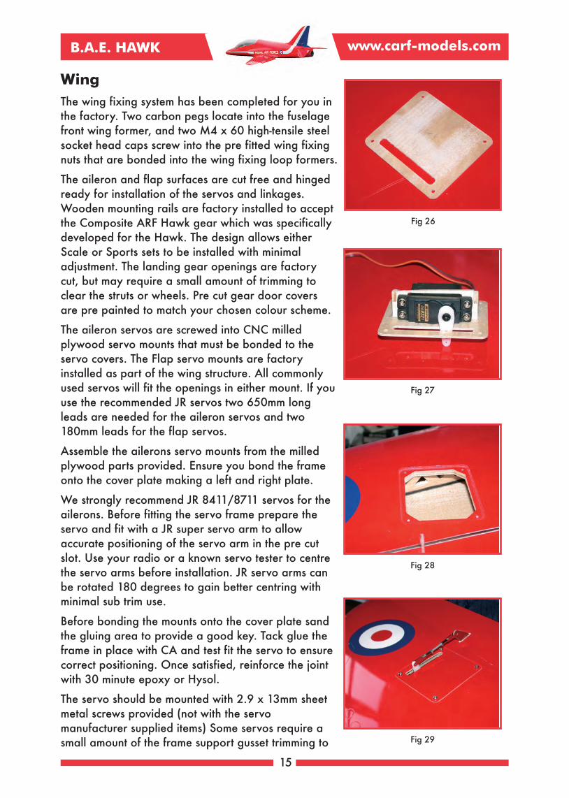
The wing fixing system has been completed for you inthe factory. Two carbon pegs locate into the fuselagefront wing former, and two M4 x 60 high-tensile steelsocket head caps screw into the pre fitted wing fixingnuts that are bonded into the wing fixing loop formers.
The aileron and flap surfaces are cut free and hingedready for installation of the servos and linkages.Wooden mounting rails are factory installed to acceptthe Composite ARF Hawk gear which was specificallydeveloped for the Hawk. The design allows eitherScale or Sports sets to be installed with minimaladjustment. The landing gear openings are factorycut, but may require a small amount of trimming toclear the struts or wheels. Pre cut gear door coversare pre painted to match your chosen colour scheme.
The aileron servos are screwed into CNC milledplywood servo mounts that must be bonded to theservo covers. The Flap servo mounts are factoryinstalled as part of the wing structure. All commonlyused servos will fit the openings in either mount. If youuse the recommended JR servos two 650mm longleads are needed for the aileron servos and two180mm leads for the flap servos.
Assemble the ailerons servo mounts from the milledplywood parts provided. Ensure you bond the frameonto the cover plate making a left and right plate.
We strongly recommend JR 8411/8711 servos for theailerons. Before fitting the servo frame prepare theservo and fit with a JR super servo arm to allowaccurate positioning of the servo arm in the pre cutslot. Use your radio or a known servo tester to centrethe servo arms before installation. JR servo arms canbe rotated 180 degrees to gain better centring withminimal sub trim use.
Before bonding the mounts onto the cover plate sandthe gluing area to provide a good key. Tack glue theframe in place with CA and test fit the servo to ensurecorrect positioning. Once satisfied, reinforce the jointwith 30 minute epoxy or Hysol.
The servo should be mounted with 2.9 x 13mm sheetmetal screws provided (not with the servomanufacturer supplied items) Some servos require asmall amount of the frame support gusset trimming to
15
Fig 29
Fig 27
Fig 28
Fig 26

B.A.E. HAWK www.carf-models.com
clear the servo wire as it exits the servo case.
The aileron servo extension should run along the wingin front of the main wing spar before passing throughthe spar around the centre section. The extension leadmust be restrained where it runs past the flap linkage.
The Aileron linkage is assembled from the 42mmlength of M3 all-thread fitted with a locking nut ateach end and an M3 steel clevis. Fit this on the outerhole of a 20mm radius arm.
Finally fix the servo cover plate using four 2.9 x10mm sheet metal screws.
The flap servos are mounted into the servo cut-out precut in the wing rib accessible through the main gearopening in the wings lower surface. The servo ismounted with the servo arm nearest the wing trailingedge.
We recommend a servo with minimum 9.0kg torqueas the Hawk flaps are quite large and the actuatinghorn offset from the hinge point is relatively small.
C-ARF strongly recommends using the JR 8411/8711servo for the flaps, fitted with a heavy duty servo arm.Very little movement is needed for total flap travel, so
the arm can be cut leaving only the inner two holes.
The flap servos are fitted using four 2.9 x 13 sheet metal screws-note do not use thestock servo mounting screws
Some time should be spent cleaning up the factory cut openings for the flap linkage witha file to remove any material left around the opening. This will stop any binding of thelinkage during flap operation. At least 60mm of flap movement is required in landingmode.
The flap linkage is assembled using two M3 x 200mm all-thread rods fitted with alocking nut at each end and a steel M3 clevis. This benefits from some additional
16
Fig 30
Fig 31
Fig 32 Fig 33
B.A.E. HAWK www.carf-models.com
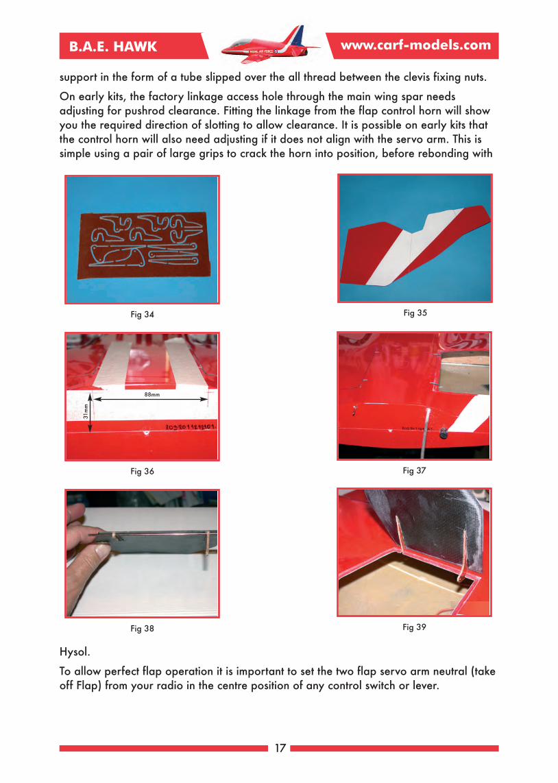
support in the form of a tube slipped over the all thread between the clevis fixing nuts.
On early kits, the factory linkage access hole through the main wing spar needsadjusting for pushrod clearance. Fitting the linkage from the flap control horn will showyou the required direction of slotting to allow clearance. It is possible on early kits thatthe control horn will also need adjusting if it does not align with the servo arm. This issimple using a pair of large grips to crack the horn into position, before rebonding with
Hysol.
To allow perfect flap operation it is important to set the two flap servo arm neutral (takeoff Flap) from your radio in the centre position of any control switch or lever.
17
Fig 35
Fig 36
Fig 38 Fig 39
Fig 37
Fig 34
88mm
31mm

B.A.E. HAWK www.carf-models.com
Main gear door installation.
The main gear doors are supplied moulded in one piece. These should be separatedinto three pieces, the larger inner section is hinged using the milled phenolic hinges andthe supplied rod and tube. The centre section will be fitted to the struts and the smallbase piece notched to clear the strut, or hinged if you chose.
Operation of the inner doors requires two large bore approx 1.5” stroke air rams. Thesecan be bought as part of the optional Composite ARF air pack #200550 or sourcedindividually. We recommend Robart 3/8” air cylinders F-RB165. These are angled andoverlap each other in the wing centre section.
The hinges need separating from the phenolic sheet and the retaining tags sanding off.It is good practise to tack glue the hinges and tubes in position to allow easy adjustment
18
Fig 41Fig 40
Fig 45
Fig 43
Fig 44
Fig 42

B.A.E. HAWK www.carf-models.com
and ensuring perfect operation before final fixing.
With the door pieces separated spend some time sanding the door recess to remove anyhigh spots and chamfer the door edges so that they seat fully in the recess.
For the doors to operate properly the hinge tubes need to be bonded to the wing skindirectly. The moulding process means it is possible that the foam skin could encroachinto the hinge tube area. This is no real problem as the foam easily sands away using around file.
Access to the hinge wire is through the wings leading edge centre section. Drill two 3mmholes at 88mm centres and 31mm down from the wings seam/joint line.
To check the foam board position use a small mirror, if necessary clean away the foamto allow the plastic hinge tubes to be bonded onto the wing skin.
Tack glue the hinges onto the gear doors with the rear hinge 13mm from the backcorner and 82mm between the two hinges.
The hinges require slots cutting in the wing gear door shut. Use the doors complete withhinges as a reference and mark the wing slot positions.
Carefully cut the slots, ensuring they are only fractionally wider than the phenolichinges. Cut three pieces of the white 3mm dia plastic tube provided, one long length tomatch the distance between the hinges fitted to the doors and two 20mm long lengthsfor outside each hinge. The Hawk has such a large gear opening and thick wing it iseasy to work on one door at a time and access the hinges through the opposite dooropening. The use of a mirror will help with the hinge tube installation.
19
Fig 46 Fig 47
Fig 48 Fig 49
B.A.E. HAWK www.carf-models.com
When satisfied with the hinge positioning, and opening angle, the hinges and tubes canbe fully bonded in position. On a Hawk the main doors open to around 85 degrees.
To aid cylinder clearance fitting ball link ends will allow one cylinder to be attached tothe inside and the opposite attached to the outside of the hinges. The Robart cylindersrequire 2-56 threaded studs and suitable ball ends. The bases of all Robart cylinders areconveniently fitted with a mounting base. This should be screwed to a scrap of 3mmplywood approx 20 x 20mm.
The air cylinders should be fully extended and the gear door open position set beforebonding the cylinder mounts to the wing upper skin. This process should allow thecylinders remaining stroke to act on the gear doors holding them shut against airpressure in flight.
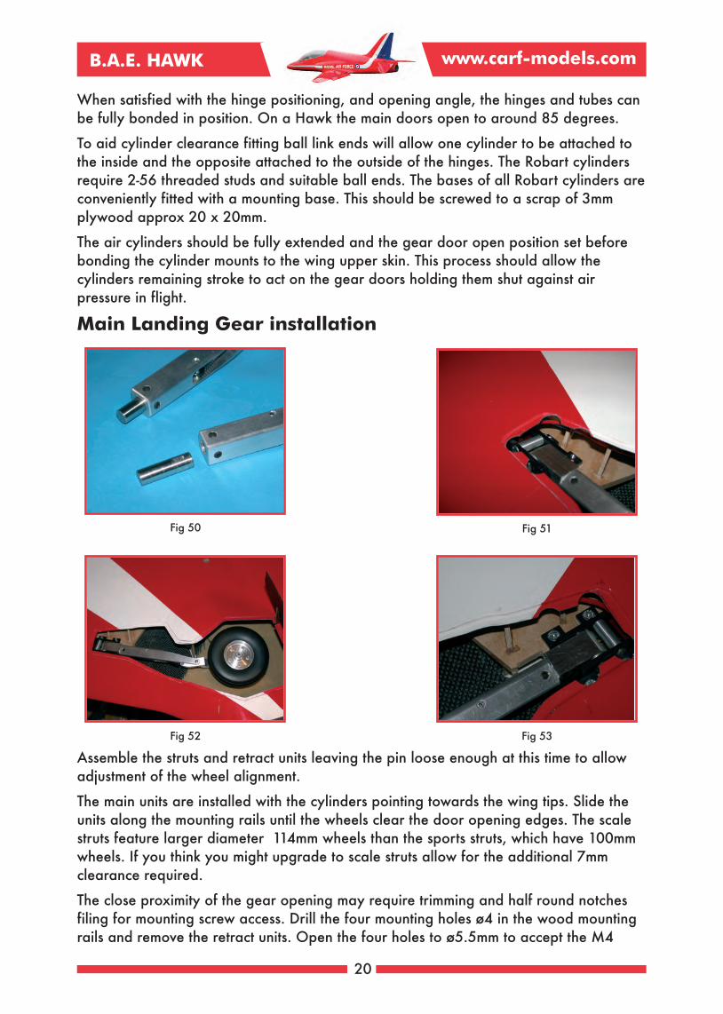
Main Landing Gear installation
Assemble the struts and retract units leaving the pin loose enough at this time to allowadjustment of the wheel alignment.
The main units are installed with the cylinders pointing towards the wing tips. Slide theunits along the mounting rails until the wheels clear the door opening edges. The scalestruts feature larger diameter 114mm wheels than the sports struts, which have 100mmwheels. If you think you might upgrade to scale struts allow for the additional 7mmclearance required.
The close proximity of the gear opening may require trimming and half round notchesfiling for mounting screw access. Drill the four mounting holes ø4 in the wood mountingrails and remove the retract units. Open the four holes to ø5.5mm to accept the M4
20
Fig 51Fig 50
Fig 53Fig 52

B.A.E. HAWK www.carf-models.com
T-nuts.
Some of the T-nuts will require trimming for structure clearance. Before installing thenuts apply a small amount of grease into the threads to stop glue locking the screws in
position. Apply a small amount of 30 minute epoxy onto the nuts and partially pull intoposition using an M4 x 15 cap head screw and a large M4 washer. Do not pull themfully home to allow final seating with the retract units in position. Working quickly reinstall the units and pull the T-nuts fully home by tightening the retract units fully. Allowthe epoxy to fully cure before removing the units.
The steel retract/oleo pins require flats grinding to stop the hardened pins slipping in theoleo leg. Insert the pin leaving 18mm protruding from the oleo leg and mark the fourgrub screw positions to aid grinding the flats. Ensure the flats do not have sharp cornersas these create stress points where the pin can crack.
Use a thread locking compound like loctite to install the four set screws in each leg.Install the oleo legs back in the retract units and nip the clamp screw just tight enough tohold the leg in position.
With both legs installed ‘eye ball’ the wheels and use a straight edge held on the
outside edge of the tyre to check alignment.
Aircraft tracking is better with a very slight ‘toe in” on the wheels, but straight wheelsare better than ‘toe out’ which can lead to instability on the ground. Test the wheelclearance during retraction and check that the main wheels clear the gear doors when
21
Fig 57
Fig 55
Fig 56
Fig 54

B.A.E. HAWK www.carf-models.com
fully retracted. If tyre clearance is tight a thin plywood shim under the retract unit tolower the wheel when in the retracted position should be added. Once you have foundthe perfect position fully lock the legs by tightening the lock screws fully.
The wing structure features convenient openings to allow the air tube to be easily routedthrough the wing to the centre section. The services (air and servo) can exit the wingeither through the top surface, or if you may fit a smoke system it is best to exit thewings leading edge between the wing pegs.
The lower leg gear door covers are mounted using a shaped piece of wood glued to thegear door with epoxy, and bonded to the oleo leg using a silicon adhesive. Additionalsecurity is gained by drilling through the door and spacer and tapping the alloy leg M3to accept two M3 screws.
The small door that covers the retract unit can either be notched to clear the leg orhinged as the full scale Hawk.
Nose gear
The nose unit on the Hawk is specially designed with a large strong mounting frame,perfect angles up and down, plus a positive, slop free and snag free steering system.
The steering servo moves with the nose leg removing the chance of snagged steeringcables and twisted jammed legs.
Mount the steering servo in the CNC machined frame using four M3 x 12 Allen screws
22
Fig 58 Fig 59
Fig 60 Fig 61

B.A.E. HAWK www.carf-models.com
with the arm furthest from the steering arm. The steering servo requires a strong servoarm at least 18mm between centres, using your radio set the servo arm neutral positionparallel to the steering arm fixed to the nose leg, with the wheel straight. Assemble the
linkage from two plastic ball-Links and a single length of M3 x 30 all-thread. Fix theball-links to the steering and servo arm with M3 x 16 Allen screws and M3 loc nuts. Themounting plate is notched to clear the up line air connection nipple. Some units havebeen assembled with the nipple on the opposite side, you can either notch the mountingplate or switch the cylinder over. There are six mounting holes in the retract frame, butonly four are required. Before drilling the mounting holes place the nose leg in thedown position and check there is 2-3mm clearance between the back of the leg andnose former. Drill four holes ø 4mm adding a screw into each hole as you drill, thishelps ensure the holes all match. Remove the nose unit and open each hole to ø5.5mmready for M4 T-nuts. The position of the rear fixing close to the nipple notch may breakinto the cut-out, in this case the T-nut will require part of the flange removing. Install theT nuts with some slow setting epoxy glue, pull them partially home with an M4 screwand washer before installing the nose unit and tightening until fully seated. Installation ofthe nose unit is made easier if you remove the rear nose former cross link section of
wood.
Nose Gear Door
The Full scale Hawk features twin “bomb” door style nose doors, plus a single small“leg” door. Your Hawk kit includes sufficient hinges to allow the scale set up to be
23
Fig 65Fig 64
Fig 62 Fig 63

B.A.E. HAWK www.carf-models.com
produced.
This method will require two nose gear cylinders for operation, and a spring to close thesmall door. As the Composite-ARF Hawk is intended as a sports scale aeroplane manyof the team have decided to use a single nose gear door, hinged on one side only. Thismethod is much simpler than the twin set up and in flight the appearance is notchanged.
The process and hinges are the same for either set-up,you could even split the door at a later date and adda cylinder to drive the second door.
The first job is to clean up the nose gear opening,filing the two sides to be parallel just outside of thepanel line marks. The nose door is supplied mouldedto shape with a double curve front section to matchthe nose area. Cut and sand the door near themarked lines and then finally sand the door to fitinside the opening with a 0.5mm gap all-around. If thedoor is to be split cut the end small leg door off andthen cut down the centre marked lines and sand to leave the same 0.5mm gap once thedoors are hinged. Fabricate some door close stops from scrap material and placearound the nose opening. These should protrude no more than 3mm to avoid fouling thenose leg and wheel during operation.
Before fitting the hinges it is worth opening the nose unit/leg enough to allow marks tobe made denoting the areas to avoid with the hinges. On the airframe shown the hinges
24
Fig 67Fig 66
Fig 69 Fig 70
Fig 68

B.A.E. HAWK www.carf-models.com
are positioned at 35mm, 126mm and 180mm back from the front edge with the nosecylinder attached to the front pair. It may be necessary to trim the rear hinge to clearthe nose wheel steering servo which sits in the door opening in with the leg in the downposition. This depends on the depth of servo case on your servo choice. The curvednature of the nose door may require some additional bracing to maintain the shape. Weused some scrap 3mm hard balsa as shown. The supplied hinge rod should remainstraight even though the nose door area is heavily curved. The front and rear hingetubes will touch the fuselage skin, the centre tube will require supporting with somescrap balsa. By design the Hawk doors must move away from the fuselage immediatelythey start opening to guarantee smooth operation and clearance while opening.Sanding a small radius on the inside edge of all doors will reduce the chance of themcatching on the fuselage surface.
The recommended Robart air cylinders can be mounted near vertical in the height of the
25
Fig 72Fig 71
Fig 73 Fig 74
Fig 75 Fig 76

B.A.E. HAWK www.carf-models.com
fuselage. Whether you chose a single door or scale twin doors the cylinders base mountto the top inside face of the fuselage shell. The angled face will require a packing pieceapproximately 10mm thick before shaping. The cylinders should be fully extended withthe doors open, this will leave a few mm of travel when the door (or doors) close,helping to resist opening from air pressure in flight.
Inlet ducts
The intakes are moulded separately for accurate scale appearance and allowingadditional access during the construction. Your chosen scheme will be factory painted tomatch the fuselage detail making the job of fitting very simple. The fuselage shape canbenefit from a fixing screw adding in the splitter front corner. Use a piece of scrap wood
from the provided sheet and add a single self tapping screw from inside the cockpit. Therear face of the inlet is glued with epoxy after removing the shine from both surfaces.Note the lower 40mm or so does not require glue as it forms part of the front wing joint.
Equipment bay installation
Experience with the three prototype Hawk models confirms that the Hawk benefits fromas much weight kept forward in the cockpit area as possible. You are aiming for abalance point between 190mm and 200mm back from the fuselage/wing joint. If youintend using a scale cockpit set some adjustment of the battery position maybe required.
The equipment tray provided can be positioned to suit your preferred set-up, but isprobably best kept towards the front of the cockpit opening. With such a large canopyglass area painting the cockpit area in a dark colour will help give the impression of ascale cockpit, even with minimal detail added.
The radio plate has several cut-outs factory cut. The notch in one end can either be usedfor a header tank or ECU battery placement on the floor. Either side of this, slots andholes are formed for the Rx and turbine ECU allowing Velcro ties to secure them firmly.If you are fitting the recommended Powerbox unit (Evolution, Competition or Champion)the plate includes two cut-outs for the unit and wiring.
Composite ARF recommend that you fit a Powerbox unit using a true duel battery systemand featuring signal boosting electronics. This product is available through C-ARF.
We placed the header tank in front of the wing former to keep the tube from the main
26
Fig 77 Fig 78

B.A.E. HAWK www.carf-models.com
tank to the header as short as possible. If you chose to fit the tank at the forward end ofthe tray ensure large bore tubing is used to keep the pump load low.
If your intention is to fit a scale cockpit, thought should be given to keeping theequipment mounted low within the cockpit area. The Hawk features staggered pilotseating with the rear pilot mounted higher than the front, this allows you a little moreheight close to the inlet area of the cockpit.
The photos included in this section give you several ideas on the equipment layout, butthe many different turbines available will require specific requirements.
A semi scale cockpit is available from C-ARF , this can be ordered through theCARF-models site. Several manufacturers offer full scale cockpit sets that could be fittedshould you wish to “scale” the Hawk up.
If you intend fitting a cockpit now or possibly in the future it is a good idea to fit the airtanks serving both the undercarriage and brake system above the main fuel tank asthere is ample space.
The plates either side of the undercarriage nose formers make perfect platforms formounting the receiver system twin battery packs.
Even with 2.4 GHz systems it is good practise to keep a reasonable separation betweenECU, fuel pump and valves. Avoid crossing the receiver aerials with power cables.
When you plumb the fuel system, keep all tubing as short as possible. Ensure the tubeends are cut square, especially when used with any quick connect device. When usinglarger tube like Tygone, cutting a short (5mm) length and sliding this over the tube endby stretching with pliers will improve the seal by adding additional grab.
Fit the fuel system overflow outlet in the fuselage just in front of the wing break former,positioning to one side will lessen the chance of damage in the event of a touch downwithout landing gear.
Additional Fences and covers
Your Hawk kit includes various parts cut from a colour coded glass sheet. The wingfences are an important feature on the Hawk. The glassfibre fences are fitted to thewing leading edge just outboard of the aileron/flap break line. If you project a lineforward from the aileron inner edge there is a rectangular panel approximately 12mmwide and 60mm long marked 45mm back from the leading edge. The wing fence ismounted centrally on this panel using thick CA or epoxy.
Another feature of the Hawk are the fuselage fins mounted either side of where theairbrake would be positioned. Two parallel lines are marked on the fuselage makinginstallation easy. The fins are given additional support by cutting two slots to accept thelocation lugs. The fins should be firmly fixed using epoxy. The fins should be fixed withan angle of approx 115 degrees on the inside edge.
To hide the openings in the tailplane cover sides around the elevator joiner, two shapedcover plates that attach to the cross brace are provided. Ensure these plates cannot
27

B.A.E. HAWK www.carf-models.com
cause binding with full and free movement on the tailplane.
The remaining vanes and plates are optional in their fitment, study a full size Hawk toposition these scale additions.
Setting up and Balancing
The final weight of your Hawk will vary with your turbine and radio equipment choice,the prototype models varied between 11 and 12.5kg dry.
Set the Centre of Gravity at 190mm from the fuselage/wing break for the first flight withthe main tank empty and the header tank full. Further improvements in flightperformance will be seen if you laterally balance your aeroplane also.
Control throws
Experience has shown us that different pilots prefer different response “feel” so themovements and expo figures quoted should be taken as a guide only. The all flyingtailplane (elevator control) requires extra care setting up the twin servo linkage. If youcarefully matched your servos in the earlier steps, little or no binding should occur. Notewhen using digital servos some noise is normal when the control surface is moved, thepitch of the sound will raise if the servos are under extreme load. A good tip is tooperate the elevator control with each linkage in turn only connected and listen to theservos. When you connect the second linkage the sound should only change slightly.Using a Powerbox unit with matchbox facility allows additional adjustment through thecentre and extremes of movement. A range of Powerbox products are available throughC-ARF.
Starting point movements
Aileron travel 16mm up and 18mm down Expo 25-35% (Positive JR/Spectrum-NegativeFutaba)
Elevator travel 30mm up and 25mm down 25-45% (Positive JR/Spectrum-NegativeFutaba)
Rudder 35mm left and right 15-35% (Positive JR/Spectrum-Negative Futaba)
Flaps. Take-off 25mm and Landing 65mm with the recommended Centre of Gravity thereis no elevator compensation required with flap deployment.
All dimensions are measured at the root trailing edge of any surface.
28

B.A.E. HAWK www.carf-models.com
BAE Hawk Hardware BagsRear Fuselage/Rudder/Stab
12 Sheet Metal Screw 2.9 mm Servo screw3 M4 x 12 allen bolt stab servo frame mount3 M4 washer stab servo frame mount3 M4 T-Nut stab servo frame mount6 Control horn (3mm hole) (later will be installed) stab and rudder3 Ball links M3 stab and rudder3 Steel Clevises M3 stab and rudder Servo3 M3 x 16 mm allen bolt for ball link fixture3 M3 lock nut for ball link fixture4 M4 x 25 allen bolt for stab mounting1 M3 all thread (100 mm long) rudder linkage2 M3 all thread (60mm long) elevator linkage1 200 x 100 mm fiberglass sheet stab spades (covers)1 M4 x12 allen bolt rear hatch mount2 2mm steel pin 250 mm long gear door hinging2 3mm plastic tube 250 mm long gear door hinging1 milled phenolic board nose gear door hinges4 M4 x 16 allen bolts gear mounting4 M4 T nuts gear mounting2 M3 ball link nose gear steering1 all thread M3 (25 mm long) nose gear steering2 M3 x 16 mm allen bolt nose gear steering2 M3 lock nuts nose gear steering1 M4 x 16 allen bolts canopy fixing screw
carbon axle, ball bearings and carbon stab mount are pre-installed in fuselageAllen bolt M4x20 for fin fixture is pre-installed in finmilled wood parts for stab servo frame, not assembled
Wing
16 Sheet Metal Screws 2.9 mm Servo screw8 sheet metal screws 2.2mmServo hatch screw8 steel clevis M3 aileron and flap linkage8 M3 nuts aileron and flap linkage2 all thread M3 (42 mm long) aileron linkage2 all thread M3 (200 mm long) flap linkage2 servo hatch (maybe taped on the wing?) aileron servo2 M4 x 60 mm allen bolts wing bolts4 allen bolts M3 x 20 gear door leg cover mount1 aluminum tube ID 3mm, 100 mm long gear door leg cover spacer1 2mm steel pin 250 mm long gear door hinging1 3mm plastic tube 250 mm long gear door hinging1 milled phenolic board main gear door hinges8 M4 x 16 allen bolts Gear mounting8 M4 T-nuts Gear mounting2 servo hatch wood mounting frame part of CNC wood plate
Turbine installation
4 M4 x 20 allen bolts Turbine mounting4 M4 T-nuts Turbine mounting4 2.2 mm sheet metal screws thrust tube mount2 Small aluminium angles Bell mount mounting angles3 M3 x 10 allen screws Carbon deflector fixing screws3 M3 nuts Carbon deflector fixing nuts1 Carbon Deflector Duct1 Double wall tail pipe tube1 Carbon Bell mouth
29

B.A.E. HAWK www.carf-models.com