Embed Size (px)
Citation preview

3/28/2011Proceedings of the 2011 ASEE NC & IL/IN Section Conference
Copyright © 2011, American Society for Engineering Education
Page 1 of 12
COMPONENT TESTING WITH
CAN-BASED INSTRUMENTATION
David McDonald
Lake Superior State University
Sault Ste Marie, Michigan
Email: [email protected]
Abstract
This paper presents the introduction of CAN-based instrumentation within vehicle
instrumentation and electric vehicle courses in electrical engineering for computer, electrical and
mechanical engineering students. The Vector CANoe and MATLAB Vehicle Network Toolbox
software packages are introduced to acquire and analyze data in typical component testing
applications. Assessment outcomes from preliminary CAN instruction are presented.
Introduction
Component performance and temperature testing is standard practice in industry, and it is also
introduced in education laboratory experiences. It is common practice to equip developmental
motors and other components with temperature and other sensors to acquire critical data that is
analyzed to validate design model integrity and device performance.
A classic temperature measurement example in electrical machinery education and in industry is
the standard temperature rise test. This test consists of attaching external temperature sensors to
the Device Under Test (DUT) and simply running the DUT at rated load to monitor the
temperature rise. Temperature data is then analyzed to ensure that the temperature did not
exceed insulation temperature limits because elevated temperatures degrade the insulation’s
lifespan.
In modern complex instrumentation and control systems that are encountered in Internal
Combustion (IC) or Hybrid / Electric Vehicles (HEV/EV) instrumentation the physically
cramped location of the selected component and the immense number of wiring terminations
make bus communication essential. Electronic Control Units (ECUs) make use of the distributed
computing nature of Controller Area Network (CAN) bus communications to transmit vital
instrumentation and control data over a simple pair of wires or CAN bus.
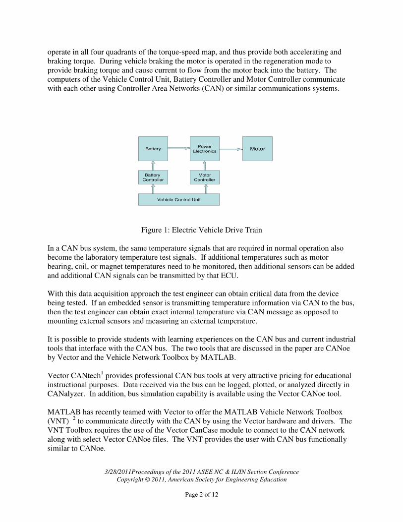
A commercial example of CAN communications is illustrated in the block diagram of an electric
vehicle drive train that shown below in Figure 1: Electric Vehicle Drive Train. In the diagram,
the battery is a cluster of Lithium Ion cells and supplies 300+ volts DC voltage at a high current
to the power electronics stage. The power electronics stage inverts the battery DC voltage into
three-phase AC voltage at the proper frequency and voltage for the motor to meet the requested
speed and torque. The motor is a high efficiency, permanent magnet synchronous motor that can
3/28/2011Proceedings of the 2011 ASEE NC & IL/IN Section Conference
Copyright © 2011, American Society for Engineering Education
Page 2 of 12
operate in all four quadrants of the torque-speed map, and thus provide both accelerating and
braking torque. During vehicle braking the motor is operated in the regeneration mode to
provide braking torque and cause current to flow from the motor back into the battery. The
computers of the Vehicle Control Unit, Battery Controller and Motor Controller communicate
with each other using Controller Area Networks (CAN) or similar communications systems.
Battery
Controller
Vehicle Control Unit
BatteryPower
ElectronicsMotor
Motor
Controller
Figure 1: Electric Vehicle Drive Train
In a CAN bus system, the same temperature signals that are required in normal operation also
become the laboratory temperature test signals. If additional temperatures such as motor
bearing, coil, or magnet temperatures need to be monitored, then additional sensors can be added
and additional CAN signals can be transmitted by that ECU.
With this data acquisition approach the test engineer can obtain critical data from the device
being tested. If an embedded sensor is transmitting temperature information via CAN to the bus,
then the test engineer can obtain exact internal temperature via CAN message as opposed to
mounting external sensors and measuring an external temperature.
It is possible to provide students with learning experiences on the CAN bus and current industrial
tools that interface with the CAN bus. The two tools that are discussed in the paper are CANoe
by Vector and the Vehicle Network Toolbox by MATLAB.
Vector CANtech1 provides professional CAN bus tools at very attractive pricing for educational
instructional purposes. Data received via the bus can be logged, plotted, or analyzed directly in
CANalyzer. In addition, bus simulation capability is available using the Vector CANoe tool.
MATLAB has recently teamed with Vector to offer the MATLAB Vehicle Network Toolbox
(VNT) 2 to communicate directly with the CAN by using the Vector hardware and drivers. The
VNT Toolbox requires the use of the Vector CanCase module to connect to the CAN network
along with select Vector CANoe files. The VNT provides the user with CAN bus functionally
similar to CANoe.

3/28/2011Proceedings of the 2011 ASEE NC & IL/IN Section Conference
Copyright © 2011, American Society for Engineering Education
Page 3 of 12
The CAN bus has been introduced in two engineering courses, EGEE365 Vehicle
Instrumentation course3,4
and also as part of the EGEE400 Electric Vehicle Systems course.
Both courses have lecture and laboratory experiences. A portion of the course content focuses
on the operation and application of the CAN bus for control and instrumentation applications.
The students perform several laboratory exercises to learn the operation of the software. Student
enrollment for both courses is open to CE, EE, and ME students who have basic electrical
circuits and C programming background. The course objectives for both courses are included as
an attachment at the end of the paper.
Vector CANoe Software
Controller Area Network (CAN) applications harness the power of distributed computing
systems in the form of independent micro-computer modules referred to as Engine Control Units
(ECU). CAN networks and software are used in the automotive, heavy equipment, ship, and
other vehicle industries.
The CANoe software by Vector is a development platform for professional network development
software that includes CANdb (the message and signal database), CANalyzer (bus analysis tool),
and CAPL (Communication Application Programming Language).
Students learn to use CANoe to simulate CAN network operation or to obtain data from a CAN
network. They can also simulate nodes on an existing network and implement test scripts. A
CANoe panel is shown below in Figure 2: Vector CANoe. The simple software configuration
that is demonstrated represents a laboratory practical exercise from EVEE400. In this example
there is one message, MotorData, with an ID of 230, and that message contains two signals:
Motor Speed and Motor Torque. The Data window and Graphics window show that the current
speed data is 80 RPM and the current torque data is 30 Nm. The Statistics window shows that
the message is being received 10 times per second.
3/28/2011Proceedings of the 2011 ASEE NC & IL/IN Section Conference
Copyright © 2011, American Society for Engineering Education
Page 4 of 12
Figure 2: Vector CANoe
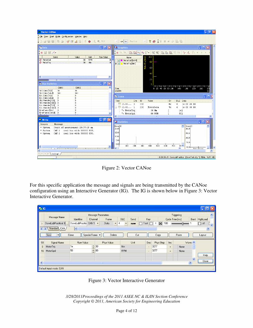
For this specific application the message and signals are being transmitted by the CANoe
configuration using an Interactive Generator (IG). The IG is shown below in Figure 3: Vector
Interactive Generator.
Figure 3: Vector Interactive Generator

3/28/2011Proceedings of the 2011 ASEE NC & IL/IN Section Conference
Copyright © 2011, American Society for Engineering Education
Page 5 of 12
As part of the CAN instruction students learn how to create the database of messages and
signals, setup a bus analysis or simulation session, program node response using CAPL, and
program the GUI displays. CAN programming gives students the background to enter the
industrial setting and acquire key variable data that is contained in message signals. In a testing
environment this software is vital to acquire key Device Under Test (DUT) data such as Motor
Temperature, Per Unit Power, Speed, or Per Unit Torque.
MATLAB Vehicle Network Toolbox
The MATLAB Vehicle Network Toolbox (VNT) enables the user to connect to the CAN
network and send/ receive CAN signals directly from MATLAB or Simulink. The user can
encode, decode, and filter industry standard CAN messages and signals using a standard CAN
database. This interface uses the Vector CANcase hardware and key software support files.
The VNT toolbox allows the user to easily obtain key CAN information and analyze and plot it
in MATLAB. The Toolbox also interfaces with Simulink, and can be used to validate Simulink
models. The user can communicate with the CAN bus directly from MATLAB or Simulink to
correlate and synchronize CAN messages with other data and monitor CAN bus traffic. The
Vehicle Network Toolbox requires that the Vector CAN Case driver software be installed and
that the Vector CANcase hardware be used for the CAN bus interface.
The Vehicle Network Toolbox will enable the user to configure a channel on the CAD device to:
• Transmit / Receive CAN bus messages and monitor message traffic
• Use the CAN database to construct messages to transmit.
• Attach the database to the configured CAN channel to interpret received CAN messages
• Log and record messages and analyze them in MATLAB
• Replay a recorded sequence of messages in MATLAB and trigger a callback function to
run when the channel receives a message
• Build Simulink models to connect to a CAN bus and to simulate message traffic
To receive signals using the Vehicle Network Toolbox , the MATLAB script follows the
workflow plan of creating a CAN channel, configuring the channel properties, starting the
configured channel, receiving messages, extracting data from messages and storing it as a
variable, disconnecting the channel, and cleaning up the Workspace.

3/28/2011Proceedings of the 2011 ASEE NC & IL/IN Section Conference
Copyright © 2011, American Society for Engineering Education
Page 6 of 12
Example MATLAB code for this process is presented below in Figure 4: Typical MATLAB
Vehicle Network Script. This specific example was developed by students as a special project in
the EGEE365 Vehicle Instrumentation course.5
% Example CAN Script
% Script transmits message on Channel 1 and received on Channel 2
% Assign Channels to a variable
% Syntax: 'Device Type' 'Device Name' 'Channel'
canch1 = canchannel('Vector','CANcaseXL 1',1);
canch2 = canchannel('Vector','CANcaseXL 1',2);
% Initialize channels
start(canch1);
start(canch2);
% Loop for user to eneter numbers to send as a message
for j = 1:10
k = input('Enter a number to transmit: ');
% Create a message variable
% Syntax: 'Message ID' 'Extended ID True/False' 'Number of Bits'
samplemessage = canMessage(500, false, 8);
% Convert message to be transmitted
% Syntax: 'Message Name' 'Data' 'Start Bit' 'signal Size' 'Bit Format'
pack(samplemessage, k, 0, 16, 'LittleEndian');
samplemessage
% Transmit message
% Syntax: 'Transmitting Channel Name' 'Message Name'
transmit(canch1, samplemessage);
% Display Channel Info
canch1, canch2
% Receive Message and Assign a Variable Name
% Syntax: 'Receiving Channel Name' 'Transmitting Channel Number'
messagein = receive(canch2,1);
% Extract Data From Message and Store as a Variable
% Syntax: 'Received message name' 'Start bit' 'Signal Size'
% 'Bit Format' 'Data Type'
value = unpack(messagein, 0, 16, 'LittleEndian', 'int16');
store(j) = value;
end
j = 1:10;
plot(j,store)
% End Channel Use and Clear Channel Data
stop(canch1),stop(canch2),clear canch1
Figure 4: Typical MATLAB Vehicle Network Script.
Example Laboratory Exercise for CAN Software
An example laboratory application of CAN software is a current student project in the EE400
Electric Vehicle Systems course. In this laboratory the speed of a motor is measured, transmitted
via CAN, and received by both the Vector CANoe Environment and by the MATLAB Vehicle
Network Toolbox environment. The students working on the project have access to prior student
work with the VNT Toolbox by a student team last year.

3/28/2011Proceedings of the 2011 ASEE NC & IL/IN Section Conference
Copyright © 2011, American Society for Engineering Education
Page 7 of 12
There are two other student projects at this time in the course. In the first project CAN vehicle
data will be collected from a vehicle that running on a dynamometer. The dynamometer is an
eddy current, vehicle chassis dynamometer that was donated to the university and refurbished as
a senior project in 2008 – 2009. In the second project the students are learning to acquire data
using National Instruments6 Data Acquisition Board NI-USB-6215 and LabVIEW software, and
then transmit the data via CAN using a National Instruments Data CAN Card NI-USB-8473.
Assessment Information
This section will present assessment information that was acquired from course offerings that
introduced the operation and programming of Vector CAN hardware and CANoe software.
During Spring 2008 the EGEE300 Vehicle Instrumentation course was taught as a special topics
course. The students were mechanical engineering majors who were completing a Vehicle
Systems option within the ME degree. The course prerequisites were EGEE210 Circuit Analysis
and EGNR265 C Programming.
The instruction concentrated on the CANoe software for CAN bus analysis and simulation.
There is no appropriate textbook for the CAN instruction so instructor generated notes and
laboratory exercises were developed. The Vector CAPL Programming Manual was also used as
a reference book.
The assessment outcomes are shown below in Figure 5: Assessment Summary of EGEE300
Special Topics Course. The outcomes reflect that the students enjoyed the course and felt
successful at mastering the course content. The course concluded with an exercise that required
the students to create a vehicle drive profile and transmit appropriate vehicle control data.

3/28/2011Proceedings of the 2011 ASEE NC & IL/IN Section Conference
Copyright © 2011, American Society for Engineering Education
Page 8 of 12
Objective Brief Description
Student
Assessment
1 Create LabVIEW programs 87%
2 LabVIEW Design patterns and structures 76%
3 Interface Data Acquisition Hardware 84%
4 CAN Basics / protocols 89%
5 CAN network analysis 89%
6 CAN network synthesis 82%
EGEE300 Special Topics Spring 2008
Preliminary course to EGEE365 - Some objectives different
General Comments:
The course topic distribution.
45% learning CAN software for analysis and simulation
25% learning LabVIEW
30% applications of CAN and LabVIEW
General student comments indicated that a large number of examples, hands-on
environment, and small class size helped to enhance their confidence with the course
material on the use of the CAN network. The students indicated enjoying learning the
software and anticipated it would prove helpful on a future job.
Figure 5: Assessment Summary of EGEE300 Special Topics Course
During Spring 2010 the EGEE365 Vehicle Instrumentation course was taught for the first time as
a regular course. Again the enrollment was comprised entirely of mechanical engineering
students who were completing a Vehicle Systems option within the ME degree. The course
prerequisites were EGEE210 Circuit Analysis and EGNR265 C Programming. The textbook
LabVIEW for Everyone was used for the LabVIEW instruction. The Vector CAPL
programming manual was used for the CAN instruction along with instructor generated
materials.
The LabVIEW material was covered for roughly the first 60% of the course, and then the CAN
bus and Vector CANoe software was taught for the remainder of the course. The students
completed instructor generator laboratory exercises and two projects. The first project involved
obtaining the temperature profile across the face of a hand-held hair dryer. A stepper motor with
its shaft connected to a threaded rod was used to move the temperature sensor. The LabVIEW
program controlled the stepper motor and acquired temperature data. A second major project
involved using LabVIEW to acquire and transmit data via CAN to the Vector CAN hardware
and CANoe software.

3/28/2011Proceedings of the 2011 ASEE NC & IL/IN Section Conference
Copyright © 2011, American Society for Engineering Education
Page 9 of 12
The assessment outcomes are shown below in Figure 6: Assessment Summary of EGEE365
Vehicle Instrumentation. The first course objective was lightly covered. The second and third
objectives reflect the LabVIEW instruction and laboratory activities. Significantly more time
was spent on these objectives and the students gained more confidence with this material. CAN
instruction was the last major topic, and more time would have been beneficial for the students to
feel more comfortable with the CAN topics. While working on the projects the students
encountered difficulty when programming the software and interfacing the hardware. They
were able to overcome some of the problems, but lacked maturity and depth of experience with
the software and hardware to resolve all the interfacing problems.
Objective Brief Description
Student
Assessment
1 Describe general vehicle controls and electronic systems 68%
2 Testing procedures, evaluate and document testing outcomes 79%
3 Program LabVIEW to acquire data and control test systems 86%
4 Analysis and simulation of CAN networks 70%
5 Program interfaces with CAN, test instruments, and DAQ boards 77%
EGEE365 Vehicle Instrumentation Spring 2010
Initial Offering of EGEE365
General student comments indicated that they felt comfortable with LabVIEW. Their
comments also indicated more time on CANoe would have been helpful. They found the two
projects helpful, and felt comfortable programming until they encountered problems they didn't
know how to resolve.
The course topic distribution.
25% learning CAN software for analysis and simulation
40% learning LabVIEW
35% other topics
Figure 6: Assessment Summary of first offering of EGEE365 Vehicle Instrumentation
A special topics version of a new Electric Vehicle course is currently being offered. This course
includes a major objective relating to CAN hardware operation and software programming using
Vector CANoe. The CAN instruction used the Vector CAPL programming manual and
instructor generated materials. Assessment data for the CAN instruction is shown below in
Figure 7: Partial Assessment of first offering of EGEE400 Electric Vehicles. The students
completed instructor generated laboratory exercises and a laboratory practical exam on the use of
the software. Assessment outcomes indicate the students became comfortable with their
understanding of the CAN bus and use of the CANoe software, but did not feel they had the
confidence to resolve problems that involved troubleshooting.

3/28/2011Proceedings of the 2011 ASEE NC & IL/IN Section Conference
Copyright © 2011, American Society for Engineering Education
Page 10 of 12
Objective Brief Description
Student
Assessment
1 Explain the structure and oepration of CAN networks 90%
2 Create a CAN database. Transmit, receive and display messages 84%
3 Use the interactive generator to transmit messages 84%
4 Log messages and signal data 88%
EGEE400 Electric Vehicle Spring 2011
Preliminary Assessment of CAN topics
General student comments indicated that they had gained confidence in the operation of CAN
networks and their ability to program and use CANoe. They also indicated the laboratory
exercises helped reinforce the lecture topics. The comments also reflected that they lacked
the experience to feel comfortable troubleshooting problems when they arose.
The CAN instruction distribution.
35% learning CAN network setup and operation
35% learning CANoe software
30% progamming and create users manual
Figure 7: Partial Assessment of EGEE400 Electric Vehicles Special Topics
Summary
The Controller Area Network (CAN) is used extensively in a wide range of engineering
applications for instrumentation and control applications. The bus conveys key instrumentation
data that can be accessed and processed. The Vector CANoe and MATLAB Vehicle Network
Toolbox are two industrial software tools that are available at attractive educational pricing for
engineering education applications. Adequate time must be allocated for the students to feel
comfortable using the software, and extended time and experience is required before students
feel comfortable troubleshooting more complex problems. Manufacturer documentation is
helpful for software instruction, but it must be supplemented with instructor generated laboratory
exercises and class handouts.
References 1. http://vector-cantech.com
2. http://www.mathworks.com/products/vehicle-network/
3. McDonald and Hildebrand, “Laboratory Learning Experiences Vehicle Engr”, SAE World Congress, 2010
4. McDonald ”Data Acquisition Applications in a Vehicle Instrumentation Course”, ASEE NC 2010
5. Moore, Bach, Parker, “Interfacing CAN Network with MATLAB, EGEE365 Project Paper and Demonstration
Handout, LSSU, 2010.
6. http://www.ni.com

3/28/2011Proceedings of the 2011 ASEE NC & IL/IN Section Conference
Copyright © 2011, American Society for Engineering Education
Page 11 of 12
Attachment 1: Course Objectives EE365 Vehicle Instrumentation
1. Describe general vehicle controls and electronic systems.
a. describe battery, power electronics, motor and control in electric vehicles.
b. use sensors, test instruments, and in-vehicle networks to acquire vehicle test data
2. Design and implement testing procedures, evaluate component or system
performance and control operation, and document testing outcomes:
a. develop preliminary test setup processes to test components,
b. write preliminary test procedures to conduct tests,
c. write laboratory reports on lab exercises.
3. Write data acquisition programs using LabVIEW to acquire data and control test
systems:
a. program data acquisition and instrument control applications,
b. use standard design patterns and error handling techniques,
c. program control structures, event structures, and GUI panels, and
d. comment and document software scripts and programs
4. Analyze the operation and simulation of CAN Networks:
a. explain the structure and operation of CAN and other typical vehicle networks,
b. create a CAN database; transmit, receive, display, and log messages,
c. write CAPL programs to transmit & receive messages, and analyze data,
d. use CANoe and CAPL programs to simulate multi-node networks.
5. Program interfaces with CAN, test instruments, and data acquisition computer boards:
a. use Measurement Automation Explorer to setup and test DAQ hardware,
b. program analog and digital I/O with LabVIEW and MATLAB DAQ, and
c. program CAN interfaces with LabVIEW and MAX.

3/28/2011Proceedings of the 2011 ASEE NC & IL/IN Section Conference
Copyright © 2011, American Society for Engineering Education
Page 12 of 12
Attachment 2: Course Objectives EE400 Electric Vehicle Systems
1. Describe electric, internal combustion and hybrid vehicles.
a. describe major components of electric and hybrid vehicles
b. describe charging systems, electric grid interface, and need for technical and
safety training.
c. describe the major components of the electric vehicle drive train.
2. Describe the basic vehicle mechanics that relate electric vehicle performance.
a. describe the for determining vehicle energy requirements and predicting
vehicle range.
b. describe roadway terms such as grade, traction force, propulsion power, and
velocity profile.
c. develop a sample drive cycle profile and determine required EV energy
resources.
3. Describe basic battery energy storage systems.
a. explain general battery terminology and the operation typical battery systems.
b. explain the role of battery management systems, state of charge measurement,
battery cell management, battery charging, monitor battery system safety
including battery integrity, electrical contactors, pre-charge safety systems,
and safety and shut down considerations.
c. explain the operation of alternative energy storage systems such as fuel cells
and ultra-capacitors.
4. Describe basic electrical motor systems.
a. apply the relationships of current, voltage, true/reactive/apparent power in
electrical systems.
b. explain motoring and regeneration, and the four quadrant torque-speed
quadrant map.
c. calculate efficiency and power factor using voltage, current, power, speed and
shaft torque data.
d. explain the general operation of high-efficiency DC permanent magnet
synchronous motors.
5. Describe power electronics systems in hybrid and electric vehicles.
a. explain the difference between rectifier and inverter systems.
b. explain the operation of power electronic switching components,
c. explain the general operation of DC-DC and DC-AC converters,
6. Analyze the operation and simulation of CAN Networks:
a. explain the structure and operation of CAN and other typical vehicle
networks,
b. create a CAN database and transmit, receive, display, and log messages,
c. use CAN systems and MATLAB to acquire and analyze sensor data