Embed Size (px)
Citation preview

ComPoint™
The music lover’s intercom solution
Instruction Manual

2
SAFETY PRECAUTIONS
1. Read these instructions.
2. Keep these instructions.
3. Heed all warnings.
4. Follow all instructions.
5. Do not use this apparatus near water.
6. Clean only with dry cloth.
7. Do not block any ventilation openings. Install inaccordance with the manufacturer’s instructions.
8. Do not install near any heat sources such as radi-ators, heat registers, stoves, or other apparatus(including amplifiers) that produce heat.
9. Do not defeat the safety purpose of the polarizedor grounding plug. A polarized plug has twoblades with one wider than the other. A groundingplug has two blades and a third grounding prong.The wide blade or the third prong is provided foryour safety. If the provided plug does not fit intoyour outlet, consult an electrician for replace-ment of the obsolete outlet.
10. Protect the power cord from being walked on orpinched, particularly at plugs, convenience recep-tacles, and the point where it exits from theapparatus.
11. Use only attachments or accessories specifiedby the manufacturer.
12. Use only with the cart, stand, tripod, bracket, ortable specified by the manufacturer or sold withthe apparatus. When a cart is used, use cautionwhen moving the cart-apparatus combination toavoid injury from tip-over.
13. Unplug this apparatus during lightning storms orwhen unused for long periods of time.
14. Refer all servicing to qualified service personnel.Servicing is required when the apparatus hasbeen damaged in any way, such as the powersupply cord or plug is damaged, liquid has beenspilled or objects have fallen into the apparatus,or the apparatus has been exposed to rain ormoisture, does not operate normally, or has beendropped.
If you have any questions, call Russound at800.638.8055 or 603.659.5170.

3
TABLE OF CONTENTS
USER SECTION
Welcome to ComPoint™ 4
About this manual 5
What’s in your ComPoint system 6–8
Using your ComPoint system 9–15
Things you’ll need to know 9
Paging 9
Intercom 10
Door station call 11
Door strike release 12
Listen mode 13
Do Not Disturb mode 14
Combined Listen and DND modes 15
INSTALLER SECTION
About this section 16
Product summary 16–18
ISH1 Hub 17
System keypads 17
ISK1 Basic Keypad 17
ISK2 Advanced Keypad 17
ISK3 Door Station 18
ISDR1 Door Strike Release Module 18
Keypad backlight color selection 18
Device installation and trim 19
Wiring and connections 19–21
110 punch-down connections 19
Speaker connections 20
Hub modular connections 20
Doorbell connections 20
Door strike release connections 21
Programming 21–27
Overview 21
Doorbell chimes 22
Hub ID numbers 22
Zone and door station labels 23
Assigning zone labels 24
Assigning door station labels 25
Viewing system information 25
Restoring factory settings 25
Programming flow charts 26–27
Detailed function descriptions 28–31
Communication priority levels 28
Paging 28
Intercom 28
Door station call 29
Door strike release 30
Listen mode 30
Audible keypad volume level indication 31
System busy 31
Do Not Disturb (DND) mode 31
Keypad backlight 31
System function test 32
Troubleshooting chart 33
REFERENCE SECTION
Technical specifications 34
Warranty 35

4
USER SECTIONIntroduction
Welcome to ComPoint™
Thank you for choosing a RussoundComPoint system for your home or busi-ness. While you may already be familiarwith paging and intercom systems, each system works differently. We’ve designedComPoint for ease of operation and with a unique set of capabilities to meet yourcommunication needs. You’ll be pleasedwith the way the system simplifies your life,and we’re confident you’ll enjoy usingComPoint every day.
ComPoint integrates the following features:
System-wide paging
Perhaps you want to call the family to din-ner, move your party guests to the livingroom, or summon everyone in the office toan important meeting. ComPoint’s pagingfeature allows you to do all this with ease.
You can let everybody know about animportant event like a birthday or anniver-sary, or you can broadcast a message forsomeone to pick up the phone or come seeyou. Whatever announcement you want tomake throughout your home or business,paging allows you to get the word out.What’s more, if you’re paging an individ-ual, that person can reply to your pagefrom the nearest keypad.
Point-to-point intercom
One of ComPoint’s most useful functions isthe intercom feature. You need to talk with
someone in another room out of earshot,and you can’t leave the room you’re in. Thesolution? The intercom feature lets you con-tact the person directly, saving you stepsand time.
Whenever you want to reach a particularperson without disturbing the whole houseor office, the intercom feature connects youto the room the person is in. You can thinkof an intercom session as a private conver-sation while paging is a public announce-ment. Also, intercom enables two-way conversations, whereas paging is intendedfor one-way communication.
Door station call and reply
With ComPoint at your service, you don’thave to run to the door every time thedoorbell rings. If you can’t get to the doorright away, the door station call functiongives you the convenience of answering thedoor from any room.
At any keypad you can have a two-wayconversation with the caller to find out whoit is and the purpose of their visit—beforeyou even approach the door.
Doorbell chimes
With ComPoint, you can have separatedoorbell chimes for two doors. You have achoice of seven different chime tones thatyour installer can assign. Or you can use aseparate doorbell system if you prefer.

5
USER SECTIONIntroduction
Door strike release
Did someone in the family forget their keys?Did a friend drop by? ComPoint offers anoptional module that works with a doorstrike release to let you admit your visitorfrom any keypad without going to the doorin person. Imagine the convenience of nothaving to leave the baby or interrupt animportant task to go and open the door foryour visitor.
Listen to another room
Need to keep an ear open for someone?Wondering what the kids are doing? WithComPoint you’re within earshot of anyother room. Listen mode keeps you in touchwith what’s going on in any room with akeypad.
Do not disturb
When you’ve tucked your kids into bed oryou need peace and quiet in the study toconcentrate, you can switch the room key-pad to Do Not Disturb. This prevents allcommunication events from being heard inthat room.
Hands free
One of the nicest features in ComPoint isthe ability to reply to intercom calls withouthaving to touch the keypad. And when thedelivery person rings your doorbell, theycan answer your reply without having topress the Call key again.
Integration with your music system
For even greater convenience, yourComPoint system can share the speakers inyour multiroom audio system. When active,ComPoint switches the speakers over to thekeypad amplifiers in the affected rooms,momentarily interrupting the audio pro-gram. When the activity ends, the speakersresume playing your audio program.
As an alternative, ComPoint can standalone by using the optional ISSP ComPointSpeakers next to the keypads.
About this manual
This section of the manual is for you, theuser. It explains what you need to know touse and enjoy your ComPoint system.
Reading these first several pages will helpyou get the most out of your system. As youlearn, share your discoveries with others inyour family or office so they too can enjoyusing ComPoint.
The Installer section that follows providesmore technical information and gets intothe nitty gritty of how the system works. It’sintended for your installer, but you’re wel-come to read it, too.
We recommend keeping this manual in asafe, accessible place so you can refer to itwhen you need to.
6
USER SECTIONSystem Components
ISK3 Door Station
ISK1 Basic and ISK2 Advanced Keypads
1
2
3
4
5
6
7
8
9
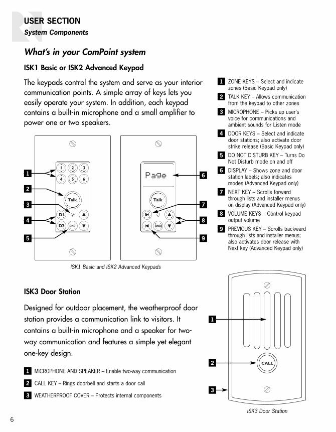
ZONE KEYS – Select and indicatezones (Basic Keypad only)
TALK KEY – Allows communicationfrom the keypad to other zones
MICROPHONE – Picks up user’svoice for communications andambient sounds for Listen mode
DOOR KEYS – Select and indicatedoor stations; also activate doorstrike release (Basic Keypad only)
DO NOT DISTURB KEY – Turns DoNot Disturb mode on and off
DISPLAY – Shows zone and doorstation labels; also indicatesmodes (Advanced Keypad only)
NEXT KEY – Scrolls forwardthrough lists and installer menuson display (Advanced Keypad only)
VOLUME KEYS – Control keypadoutput volume
PREVIOUS KEY – Scrolls backwardthrough lists and installer menus;also activates door release withNext key (Advanced Keypad only)
61
2
3
4
5
7
8
9
1
2
3
1
2
3
MICROPHONE AND SPEAKER – Enable two-way communication
CALL KEY – Rings doorbell and starts a door call
WEATHERPROOF COVER – Protects internal components
What’s in your ComPoint system
ISK1 Basic or ISK2 Advanced Keypad
The keypads control the system and serve as your interiorcommunication points. A simple array of keys lets youeasily operate your system. In addition, each keypad contains a built-in microphone and a small amplifier topower one or two speakers.
ISK3 Door Station
Designed for outdoor placement, the weatherproof doorstation provides a communication link to visitors. It contains a built-in microphone and a speaker for two-way communication and features a simple yet elegantone-key design.

POWER INPUT – For connecting a Russound ISPS power supply, 15 VDC 3.5 A
DOORBELL CHIME GAIN CONTROL – For adjusting the overall volume of thedoorbell chimes
DOORBELL CHIME SWITCHES – For selecting individual chime tones for one ortwo door stations
HUB ID SWITCHES – For assigning the hub a unique ID number in a multiple-hubsystem
DOOR STATION PORTS – For connecting ISK3 Door Stations
LINK PORTS – For connecting multiple hubs together
FIRMWARE UPDATE PORT – For updating system firmware from a computer
ZONE KEYPAD PORTS – For connecting ISK1 Basic or ISK2 Advanced Keypads
7
USER SECTIONSystem Components
ISH1 Hub
As the heart of the system, the hub keeps track of the zones and routes communicationsappropriately. It also provides your choice of chime sounds for the built-in doorbell feature, which plays chimes through the speakers in each room.
ISH1
NEWMARKET, NH USAPROGRAM OPTIONS
0=DOWN / 1=UP
DOOR BELL CHIME
DS1
NONE = 000CHIME 1 = 001CHIME 2 = 010CHIME 3 = 011CHIME 4 = 100CHIME 5 = 101CHIME 6 = 110CHIME 7 = 111
SWITCH 1-3HUB 1 = 000HUB 2 = 001HUB 3 = 010HUB 4 = 011HUB 5 = 100HUB 6 = 101
HUB ID
FIRMWARE UPDATE PORT
MADE IN CHINA
MIN MAX
DOORBELL CHIMEGAIN
1 3 5 DOOR 1
2 4 6 DOOR 2
15VDC
3.5A MAX
LINKOUTIN
DS2
1-3 = DOOR 1 CHIME
SWITCH 4 = CHIME VOLUMEUP = 50% MAX KEYPAD OUTPUTDOWN = KEYPAD ADJUSTABLE
5-7 = DOOR 2 CHIME
8 = NOT USED#4 UPDATE
RUN
ISH1 Hub
1
2
3
4
5
6
7
8
1
2 3 4
5
6
7
8

8
ISDR1 Door Strike Release Module
This optional module provides a connection point for a separate door strike release unit,making it possible to unlock the door from any keypad.
ISSP ComPoint Speaker
This optional in-wall speaker sits beside aBasic or Advanced keypad in a room withoutmultiroom audio system speakers. It can alsobe used in every room when ComPoint is usedas a stand-alone system.
ISDR1 Door Strike Release Module
ISSP ComPoint Speaker
USER SECTIONSystem Components
1
23
1
2
3
OUTPUT CONNECTOR – Punch-down connectorfor CAT-5 cable to an ISK3 Door Station
INPUT CONNECTOR – Punch-down connector forCAT-5 cable from the ISH1 hub
RELAY OUTPUT CONNECTOR – Removable con-nector for a door strike release, gate actuator,or other device

9
Using your ComPoint system
ComPoint is easy and fun to use. You’ll findthese instructions simple to follow. Take alittle time to get familiar with them so youcan start enjoying your system right away.
Things you’ll need to know
With ComPoint, we refer to areas with key-pads as zones. A zone may be a singleroom or an area with more than one room,such as a kitchen and dining area.
Every communication has a sender and areceiver. With ComPoint, we call any zonethat starts a communication the sendingzone. The zone or zones to which the com-munication is sent are receiving zones,even though they may reply to the initialcommunication. For an intercom session,the receiving zone is also the target zone.
Certain communications take priority overothers. A door station call interrupts anyother communication in progress. Paging isallowed only when there is no door stationcall or intercom session already under way.An intercom session is allowed only whenthere is no door station call or page inprogress. Paging and intercom interruptListen mode.
Your ComPoint system is configured witheither ISK1 Basic or ISK2 Advanced key-pads. The way you use your system and theway it gives you information depends onwhich keypads you have.
With either keypad, pressing the Talk keysounds a ping tone in the receiving zonesto announce your message. Releasing theTalk key sounds a double ping.
If the system is already in use when you tryto send a page or start an intercom ses-sion, the Talk key blinks red for 7 secondsto let you know the system is busy. Also, theAdvanced Keypad indicates Busy on itsLCD panel.
Paging
Paging lets you sendan announcementthroughout yourhome or businessfrom any keypad.
To send a page, justpress and hold theTalk key, then speak.Release the keywhen you’re done.
Your page will be heard in all zones exceptthose that are in Do Not Disturb mode. Forprivacy and to avoid disturbing your neigh-bors, your page will not be heard at eitherdoor station.
If a zone key is lit red on the Basic Keypad,press the key to deselect that zone beforeyou press the Talk key to send a page.
Using the Talk key for paging
USER SECTIONOperation
10
USER SECTIONOperation
If a zone label appears on the AdvancedKeypad, use the Next or Previous key toselect Page before you press the Talk key.
All keypads indicate which zone is sendinga page, so you’ll know where it’s comingfrom. The zone indication remains for 30seconds after the Talk key is released tosimplify replying to the page.
The keypads in the receiving zones alsosound a double ping when the Talk key isreleased. This lets you know the personsending the page is done speaking andyou can reply to the page. Within 30 sec-onds, simply press and hold the Talk keyand speak. Your reply will be heard only inthe zone that sent the page.
If you wish to reply to the page after the30-second limit, you can use the intercomfunction described below or a return pageto send your reply.
Intercom
Unlike a system-wide page, an intercomsession occurs only between two zones.
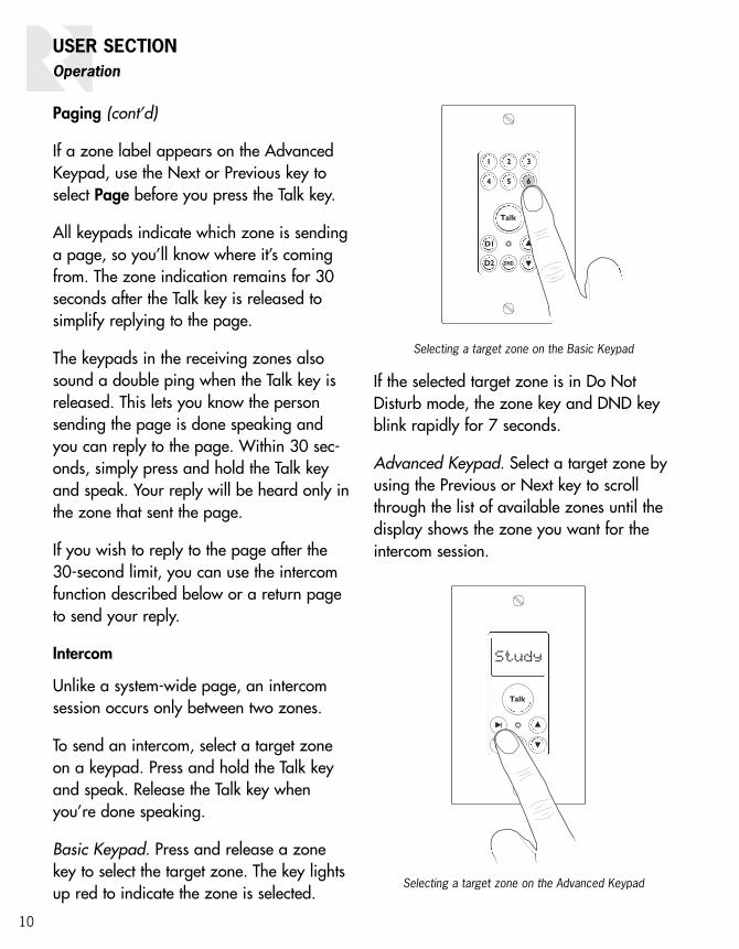
To send an intercom, select a target zoneon a keypad. Press and hold the Talk keyand speak. Release the Talk key whenyou’re done speaking.
Basic Keypad. Press and release a zonekey to select the target zone. The key lightsup red to indicate the zone is selected.
If the selected target zone is in Do NotDisturb mode, the zone key and DND keyblink rapidly for 7 seconds.
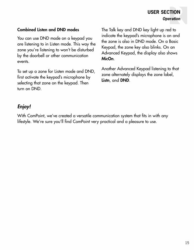
Advanced Keypad. Select a target zone byusing the Previous or Next key to scrollthrough the list of available zones until thedisplay shows the zone you want for theintercom session.
Selecting a target zone on the Basic Keypad
Paging (cont’d)
Selecting a target zone on the Advanced Keypad

11
If the selected zone is in Do Not Disturbmode, the display alternately shows thezone label and DND at 1-second intervalsand the DND key blinks rapidly for 7 seconds.
Receiving an intercom. When the Talk keyis pressed on the sending keypad, thereceiving keypad indicates which zone issending the intercom. Also, both the send-ing and receiving keypads sound a singleping to let you know you can reply handsfree within 7 seconds. After the 7 seconds,the keypads sound a double ping to signalthe end of the hands-free reply period.
After the double ping, you can reply within30 seconds by pressing and holding theTalk key while you speak. After 30 secondsyou can no longer reply, but you can startanother intercom session to the zone thatsent the original message.
Door station call
A visitor can ring the doorbell and start adoor station call by simply pressing andreleasing the Call key.
When the Call key is pressed, all keypadsindicate the calling door station for 15 sec-onds. The D1 or D2 key on the BasicKeypad blinks red and the display on theAdvanced Keypad shows Door1, Door2, oran installer-assigned door label.
The keypads also sound a doorbell chime,as long as they aren’t in Do Not Disturbmode and a chime option is selected on thehub. Additionally, the door station can ringa traditional doorbell system as well.
Using the Call key on a Door Station
Intercom (cont’d)
USER SECTIONOperation
Door call indication on Basic and Advanced keypads

12
USER SECTIONOperation
A door station call takes precedence overpaging and intercom sessions and thusinterrupts them if they’re in progress whenthe Call key is pressed.
To reply to a door station call, press andhold the Talk key on a keypad within 15seconds and speak. Release the Talk keywhen you’re done speaking. When yourelease the Talk key, the door station soundsa single ping to let the caller know they cananswer your reply.
Note: You must use the Talk key to reply to a door station call. For your privacy,ComPoint doesn’t allow a hands-free replyto a door station call.
After you reply to a door station call, thecaller has 7 seconds to answer your replyhands free. After 7 seconds, the door station pings twice to indicate the time isup.
If more than 15 seconds have passed sincethe door call, you can reselect the door sta-tion and press the Talk key to start a newsession. This does not ring the doorbell.
Door strike release
If your ComPoint system includes optionalISDR1 Door Strike Release Modules, youcan activate them from a keypad to unlockthe doors. The ISDR1 itself does not unlockthe door; rather, it provides a switch to con-trol a separate door strike release unit tounlock the door.
Basic Keypad. Press and hold the corre-sponding door station key for 3 seconds.
The module then activates for 3 secondsand the keypad and door station confirmactivation with a buzz tone.
Releasing a door strike on the Basic Keypad
Door station call (cont’d)

13
Advanced Keypad. During a door call,press and hold both the Previous and Nextkeys at the same time for 3 seconds.
When there is no current door call session,first press the Previous or Next key to scrollthrough the list to the door label. Thenpress and hold both keys for 3 seconds.
The module then activates for 3 secondsand the keypad and door station sound abuzz tone to confirm activation.
Listen mode
You can use your ComPoint system to con-tinuously listen to any single zone from oneor more other zones. To do this, first turnon a keypad microphone in the zone youwant to listen to, then select that zone onone or more other keypads.
Other communication events have priorityover Listen mode but only temporarily interrupt it.
To turn on a zone microphone, select thatzone on its own keypad. The Talk key lightsup red to indicate the keypad’s microphoneis active. On a Basic keypad, the zone keyblinks and on an Advanced Keypad, thezone label changes to MicOn after 2 sec-onds. Note: Only one zone microphonecan be on at once.
Basic Keypad Microphone On indication
Door1 Door1
Releasing a door strike on the Advanced Keypad
1 2
Door strike release (cont’d)
USER SECTIONOperation
Advanced Keypad Microphone On indication

14
USER SECTIONOperation
Basic Keypad. To listen to the zone with theactive microphone, press the zone key. Thekey blinks three times and then remains litred to indicate selection of the zone withthe active microphone.
Advanced Keypad. To listen to the zonewith the active microphone, press thePrevious or Next key to select the zone. Thedisplay will alternately toggle between thezone label and Listn as long as the activezone is selected.
To cancel Listen mode with either type ofkeypad, deselect the zone you are listeningto on the keypad in that zone. Listen modecannot be canceled from any other zone.
Do Not Disturb mode
The Do Not Disturb (DND) feature allowsyou to prevent pages, intercom sessions,door station calls, and doorbell chimesfrom being heard in a zone. Thus, you canuse DND mode to prevent interruption of amultiroom audio program in that zone.
To turn on DND mode, press and releasethe DND key. The DND key lights up red toindicate the zone is in DND mode.
To cancel DND mode, press any key on thekeypad other than Volume Up or VolumeDown.
Selecting Listen mode on the Basic Keypad
Listn
Selecting Listen mode on the Advanced Keypad
Listen mode (cont’d)
Selecting Do Not Disturb mode
15
Combined Listen and DND modes
You can use DND mode on a keypad youare listening to in Listen mode. This way thezone you’re listening to won’t be disturbedby the doorbell or other communicationevents.
To set up a zone for Listen mode and DND,first activate the keypad’s microphone byselecting that zone on the keypad. Thenturn on DND.
The Talk key and DND key light up red toindicate the keypad’s microphone is on andthe zone is also in DND mode. On a BasicKeypad, the zone key also blinks. On anAdvanced Keypad, the display also showsMicOn.
Another Advanced Keypad listening to thatzone alternately displays the zone label,Listn, and DND.
Enjoy!
With ComPoint, we’ve created a versatile communication system that fits in with anylifestyle. We’re sure you’ll find ComPoint very practical and a pleasure to use.
USER SECTIONOperation

16
INSTALLER SECTIONProduct Summary
About this section
This section of the manual provides technicalinformation for installing and programming theComPoint system. It also provides detaileddescriptions of the system functions.
Product summary
The ComPoint system uses one or more centralhubs, each of which supports up to 6 keypads.Each keypad is addressable by its own uniqueID number assigned by the hub.
ComPoint connects with CAT-5 cable, whichconveys power, ground, audio, and data
between the components. The cable length limitfor any zone or door station is 250 feet (76 m).
The system can include one or two door sta-tions connected to hub #1. Each door stationhas its own unique ID number, permanentlyassigned in the system firmware.
Each door station may also have a door strikerelease module wired in line between the huband the station.
Simple system programming is required toassign the hub ID numbers, doorbell chimes,and when ISK2 Advanced Keypads are used,zone and door labels.
ISK3 ISK3
ISK2
ISH1
ISPS
ISDR1 ISDR1
Six-zone ComPoint system with Advanced Keypads and Door Strike Release Modules

17
ISH1 Hub
As the central controller for the ComPoint sys-tem, the ISH1 hub performs all communicationsrouting. It addresses each keypad by sending amessage on the status wire in the CAT-5 cableto give the keypad its own ID number accordingto the port it’s connected to.
The hub has 6 zone keypad ports. Up to 6 ISH1hubs can be linked together for a maximum of36 zones. With multiple hubs, each hub must beassigned a unique ID number during installation.
The hub also has ports for 2 door stations. In asystem with multiple linked hubs, only the hubwith ID number 1 supports the door stations.
A separate doorbell chime tone can be selectedon hub 1 for each door. These chime selectionstake effect for the entire system and playthrough all the zone keypads.
The hub’s firmware contains a list of zone labelsfor display on the ISK2 Advanced Keypads. Thelabels are assigned to zones by the installer andstored in nonvolatile memory within the hub.
The ISH1 hub uses an external power supply toconserve chassis space. It also has a port forupdating the system firmware from a computer.
System keypads
ComPoint keypads are designed to be simple,intuitive interfaces for the user. Each model hasa Talk key, volume keys, and a DND key for set-ting the zone in Do Not Disturb mode. Bothmodels have installer-selectable amber or greenbacklighting that turns on when the system isused and turns off after the system is inactivefor 60 seconds. A built-in microphone with auto-matic gain control picks up the user’s voice.
The keypads require external speakers, whichare driven by the keypad amplifiers for commu-nications. By using built-in speaker relays, thekeypads can share the speakers used in a multi-room audio system. When ComPoint activates,
the relays switch the speakers from the audiosystem to the keypad amplifiers in the affectedzones, momentarily interrupting the audio pro-gram. When the activity ceases, the speakersare switched back to the audio system.
In the absence of a multiroom audio system, orin zones that are not shared with an audio sys-tem, the ISSP ComPoint speaker can be usedor the keypads can be wired directly to in-wall,in-ceiling, or surface-mounted speakers.
The keypad amplifier is monaural, but the relaypasses stereo signals from the audio system tothe speakers.
The keypad volume keys adjust the listeninglevel for communications by controlling the key-pad’s amplifier output. They have no effect onthe room volume for a connected audio system.
The volume keys signal the hub to send a pingtone as an audible cue for the volume levelwhen there is no communication taking place.Once the volume adjustment reaches either endof the range, the ping tone no longer sounds.
ISK1 Basic Keypad
The ISK1 Basic Keypad is designed for use in asystem with no more than six zones. Pressing azone key selects a target zone for an intercomsession.
Certain keys change to red to indicate zone ordoor station selection, incoming page or inter-com, door station call, or system busy. Whenanother zone originates a page or intercom ses-sion, that zone is indicated by a red-backlit zonekey on the ISK1.
ISK2 Advanced Keypad
The ISK2 Advanced Keypad has enhanced fea-tures to provide more user feedback and sup-port a larger system than the ISK1. It uses a 5-character LCD panel to show zone and doorstation labels and other information.
INSTALLER SECTIONProduct Summary

18
INSTALLER SECTIONProduct Summary/Installation
One of the benefits of the Advanced Keypad isthe ability to support systems as large as 36zones, since the ISK2 is able to select any ofthe zones by label. The zone and door stationlabels are dynamically served from the hub andappear in alphabetical order on the keypad dis-play. A Page label is included in the list as thedefault selection when the system is inactiveand the Talk key is pressed.
On the ISK2, the target zone for an intercomsession is selected by scrolling through thezone list. Pressing and holding the Previous orNext key scrolls through the list with a half-sec-ond delay between zone labels.
A bar graph on the display indicates the zonevolume level visually in conjunction with the audi-ble ping tones. A small pushbutton on the frontedge of the keypad is used to enter a setupmode to assign labels to the zones.
ISK3 Door Station
Unlike the Basic and Advanced Keypads, theISK3 Door Station has only one key and con-tains an internal speaker. Amplification for thespeaker is built in as with the keypads but thereis no speaker interrupt relay. A potentiometerallows adjustment of the speaker volume level.
The ISK3 also provides contacts for closing astandard doorbell circuit. These close for a mini-mum of 4 seconds to activate an existing door-bell or other device.
ISDR1 Door Strike Release Module
The optional ISDR1 Door Strike Release Moduleprovides relay contacts for activating a doorstrike release from another manufacturer. Themodule connects in the CAT-5 line between ahub and an ISK3 door station. The ISDR1 canbe located anywhere in the CAT-5 line, though itwould be preferable to have it close to the door.
The ISDR1 obtains its operational power fromthe hub. The separate door strike release mustreceive voltage from its own power source.
The ISDR1 passes signals on all leads of theCAT-5 cable except one which is used to acti-vate the module from the hub upon receiving acommand from a keypad.
By providing a normally closed (NC) relay con-tact in addition to the normally open (NO) andcommon contacts used for the door strikerelease activation, the ISDR1 can be used forother applications where a versatile relay isneeded. The ISDR1 can be activated by provid-ing 15 VDC between two of the eight positionsin the 110 punch-down input connector.
Keypad backlight color selection
Each ComPoint keypad can be set to eitheramber or green backlighting, selected by aminiature slide switch on the bottom edge ofone of the circuit boards.
Select the desired backlight color beforeinstalling the keypads.
ISK2 Advanced Keypad (cont’d)
Keypad backlight color selector switch
BR BR/W G G/W O O/W BL BL/W
Amber Green
ISK1
ISK2

19
INSTALLER SECTIONInstallation
Device installation and trim
The ISH1 hub is designed for surface mountingor installation in a structured wiring panel. Itshould be located near an electrical outlet.
The ISK1 and ISK2 Keypads are designed toinstall in standard US electrical plastic wallboxes with an internal volume of at least 18cubic inches (295 cm3). Each keypad occupiesa single gang and accepts a Decora® wall plate.
For the best accessibility, viewability, and micro-phone reception, we recommend installing thekeypads at a standard thermostat height of 58to 60 inches (1.5 m). This may vary accordingto personal preferences or requirements.
The ISK3 Door Station installs in a standard sin-gle-gang US electrical deep plastic wall box withan internal volume of at least 22 cubic inches(360 cm3). It has its own weather-resistant frontplate and thus needs no other cover plate.
The ISDR1 Door Strike Release Module is a sur-face-mount device. It should be located in anaccessible area near the door, such as an attic,basement, or closet space between the doorstation and the hub. The ISDR1 connects to adoor strike release unit, which in most caseswould be installed by a security contractor.
Wiring and connections
ComPoint system components connect withCAT-5 cable. Run CAT-5 from the hub location toevery keypad and door station location. If youare installing ISDR1 modules, loop the door sta-tion cables through the module locations.
Each keypad in the system requires one or twoexternal speakers. If the ComPoint system issharing speakers with an audio system, loopthe speaker cables through the keypad loca-tions. If dedicated speakers are being used, runthe speaker cables to the keypads.
When running CAT-5 and speaker cables, avoidrunning them near AC power wiring. If you mustrun the cables parallel to electrical wiring,space the cables at least 12 inches (30 cm)from the AC power lines.
110 punch-down connections
The keypads, door stations, and door strikerelease modules have 110 punch-down connec-tors for the CAT-5 cables. Connect the wireswith a punch-down tool as shown below.
The keypad wire functions are as follows:
Wire Color FunctionBrown Audio +
Brown/White Audio –Green Status
Green/White GroundOrange Ground
Orange/White + 15 VDCBlue Com A
Blue/White Com B
BR BR/W G G/W O O/W BL BL/W
BR BR/W G G/W O O/W BL BL/W
110 punch-down connection

20
INSTALLER SECTIONInstallation
Speaker connections
Each keypad has an 8-pole screw-terminal con-nector for accessing the internal speaker relay.This connector is typically used for connectingthe zone speakers in a multiroom audio system.In a zone where the ComPoint system does notshare speakers with an audio system, connect adedicated speaker or pair of speakers to theoutput terminals.
Note: Both speaker output channels must beconnected, since they are wired in series. If youare using a single dedicated 8-ohm speakersuch as the ISSP ComPoint Speaker, connectthe speaker to one channel and a shortingjumper to the other channel. If you are using asingle 4-ohm speaker, connect it to one channeland a 4-ohm, 2-watt power resistor to the otherchannel.
Be sure to observe polarity when connectingthe speaker wires. The standard color code for4-conductor speaker cable is as follows:
Wire Color PolarityWhite Left +Green Left –Black Right –Red Right +
Hub modular connections
The hub has 8-pole modular jacks for keypadand door station connections. The keypads con-nect to ports 1 through 6, and the door stationsconnect to DOOR1 and DOOR2. These connec-tions must be made according to the T568Astandard as shown below.
The hub also uses modular jacks for the linkports. You may use any 8-pole straight-throughRJ-45 patch cable to link hubs together.
Doorbell connections
ComPoint can operate a separate doorbell sys-tem as well as provide doorbell chime tones inthe zones. To use a separate doorbell, connecteach door station to the doorbell as shownbelow or in the doorbell system instructions.
Multiroom speaker connection to keypad
y
OUT TO SPEAKERS IN FROM AMPLIFIER
4-conductorcable fromamplifier
2-conductorcables tospeakers
L+ L- R - R+ L+ L- R- R+
Doorbell connection to rear of ISK3 Door Station
DoorbellTransformer Doorbell
8-pole modular T568A connection
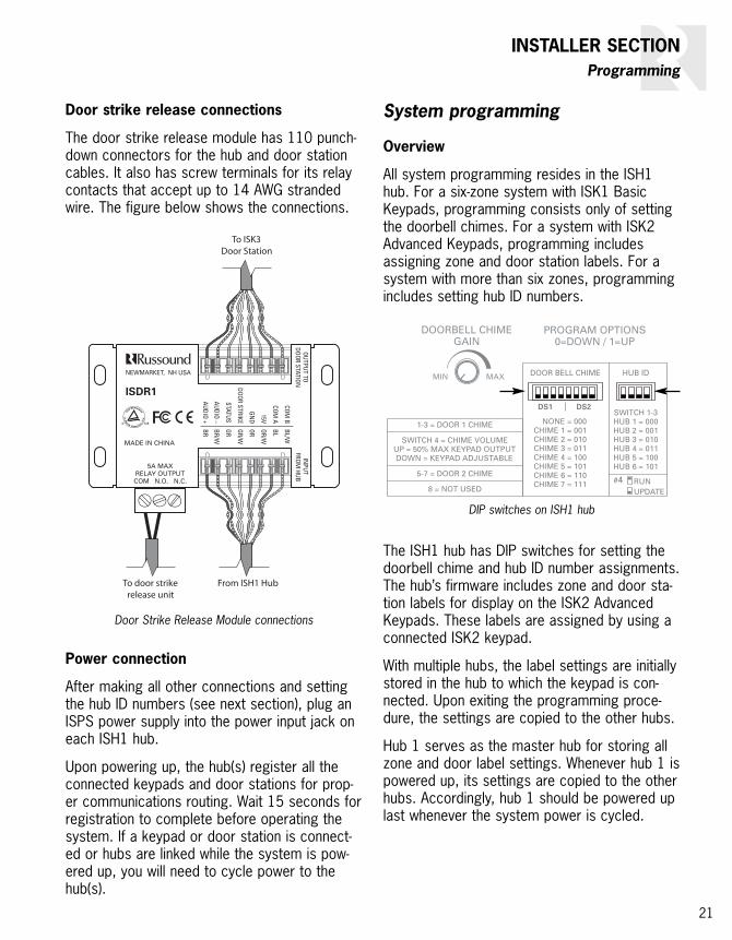
Door strike release connections
The door strike release module has 110 punch-down connectors for the hub and door stationcables. It also has screw terminals for its relaycontacts that accept up to 14 AWG strandedwire. The figure below shows the connections.
Power connection
After making all other connections and settingthe hub ID numbers (see next section), plug anISPS power supply into the power input jack oneach ISH1 hub.
Upon powering up, the hub(s) register all theconnected keypads and door stations for prop-er communications routing. Wait 15 seconds forregistration to complete before operating thesystem. If a keypad or door station is connect-ed or hubs are linked while the system is pow-ered up, you will need to cycle power to thehub(s).
21
INSTALLER SECTIONProgramming
System programming
Overview
All system programming resides in the ISH1hub. For a six-zone system with ISK1 BasicKeypads, programming consists only of settingthe doorbell chimes. For a system with ISK2Advanced Keypads, programming includesassigning zone and door station labels. For asystem with more than six zones, programmingincludes setting hub ID numbers.
The ISH1 hub has DIP switches for setting thedoorbell chime and hub ID number assignments.The hub’s firmware includes zone and door sta-tion labels for display on the ISK2 AdvancedKeypads. These labels are assigned by using aconnected ISK2 keypad.
With multiple hubs, the label settings are initiallystored in the hub to which the keypad is con-nected. Upon exiting the programming proce-dure, the settings are copied to the other hubs.
Hub 1 serves as the master hub for storing allzone and door label settings. Whenever hub 1 ispowered up, its settings are copied to the otherhubs. Accordingly, hub 1 should be powered uplast whenever the system power is cycled.
DIP switches on ISH1 hub
Door Strike Release Module connections
To door strikerelease unit
To ISK3Door Station
From ISH1 Hub

22
INSTALLER SECTIONProgramming
Doorbell chimes
A single 8-switch DIP assigns doorbell chimesfor both door stations. Switches 1 through 3select the chime for door 1 and switches 5through 7 select the chime for door 2. Thereare 7 chime options as well as a setting for nochime when a separate doorbell system isused. To select the chimes, set the switches asshown in the table below.
Switch 4 selects how the chime volume level ismanaged. Setting the switch to 1 (up) sets thechime volume level to a fixed level at 50% ofthe maximum keypad output in all zones. Thiscauses the chime to play at the same level in allzones. Setting the switch to 0 (down) allows thechime volume to be determined by the keypadvolume level setting in each zone independently.
Switch 8 is currently not used.
The ISH1 hub also has a gain control for settingthe overall volume of the doorbell chime throughthe system. This can be used to adjust thechime level relative to the communication level.
Note: In a system with multiple linked hubs,only the settings on hub 1 affect the doorbellchime assignments and volume level, since thedoor stations connect only to hub 1. Becausethe settings take effect immediately, the door-bell chimes can be set at any time. There is noneed to cycle the power after setting them.
Hub ID numbers
In any ComPoint system, there must be a hubwith ID number 1. In a multiple-hub system,each hub’s ID number must be unique. On eachhub the ID number is manually assigned on the4-switch HUB ID DIP before the system is pow-ered up. To assign the ID number, set switches1 through 3 as shown in the table below.
Switch 4 enables a programming mode forupdating the system firmware. Leave this switchin the up position for system operation.
To obtain the firmware and update instructionfiles, download them from the Document Centerat www.russound.com.
Doorbell chime switch settings
Doorbell Chime Switch Settings (0 = Down, 1 = Up)
SwitchesDoor 1 CV* Door 2
1 2 3 4 5 6 7 8
None 0 0 0 0/1 0 0 0 –Chime 1 0 0 1 0/1 0 0 1 –Chime 2 0 1 0 0/1 0 1 0 –Chime 3 0 1 1 0/1 0 1 1 –Chime 4 1 0 0 0/1 1 0 0 –Chime 5 1 0 1 0/1 1 0 1 –Chime 6 1 1 0 0/1 1 1 0 –Chime 7 1 1 1 0/1 1 1 1 –
*Switch 4 is for chime volume(0 = Keypad Adjustable, 1 = 50% Keypad Maximum)
Hub ID switch settings
Hub ID Switch Settings (0 = Down, 1 = Up)
SwitchesHub ID FW*
1 2 3 4
Hub 1 0 0 0 1
Hub 2 0 0 1 1
Hub 3 0 1 0 1
Hub 4 0 1 1 1
Hub 5 1 0 0 1
Hub 6 1 0 1 1
*Switch 4 is for firmware updates(0 = Update Mode, 1 = User Mode)

23
Zone and door station labels for AdvancedKeypads
The ISK2 Advanced Keypad shows which zoneor door station is selected by displaying a zoneor door station label. The default zone labelsare Zn#1 through Zn#36, based on the hub andport numbers the keypads are connected to.The default door station labels are Door1 andDoor2. You can assign zone labels from thetable above and door station labels from thetable to the right to replace the default labels.The hubs retain label assignments in nonvolatilememory so they won’t be affected if the systemloses power.
To assign labels you must have all hubs linkedtogether with unique ID numbers (if the systemhas multiple hubs) and an ISK2 Advanced
Keypad connected to any hub. You can use thesame keypad to assign labels for the entire sys-tem. The system must be powered up to assignlabels.
Assignable door labels for ISK2
Door Label Door Name
BDoor Back DoorFDoor Front DoorGate GateGrage GarageSDoor Side DoorSvcDr Service Door
INSTALLER SECTIONProgramming
Assignable zone labels for ISK2 Advanced Keypads
Zone Label Room Name Zone Label Room Name Zone Label Room Name
Alcov Alcove Dine Dining Room Loft Loft
Atrm Atrium Entry Entry Way MBath Master Bath
Attic Attic Famly Family Room MBed Master Bed
Baby Baby Room Foyer Foyer Nurse Nursery
Bar Bar FtYrd Front Yard Offc1 Office 1
Basmt Basement Galry Gallery Offc2 Office 2
Bath Bathroom Game Game Room Parlr Parlor
Bath2 Bathroom 2 Gardn Garden Patio Patio
Bath3 Bathroom 3 GBath Guest Bath Play Play Room
BDeck Back Deck GBed Guest Bed Pntry Pantry
Bed1 Bedroom 1 Grage Garage Pool Pool
Bed2 Bedroom 2 Great Great Room Porch Porch
Bed3 Bedroom 3 Guest Guest Room RecRm Rec Room
Bed4 Bedroom 4 Gym Gym Sauna Sauna
Bed5 Bedroom 5 Jcuzi Jacuzzi SDeck Side Deck
Bilrd Billiard Room KBed Kids Bed Shop Shop
BkYrd Back Yard Kids Kids Room SitRm Sitting Room
Blcny Balcony Kitch Kitchen State State Room
Cellr Cellar Laund Laundry Study Study
Court Courtyard Libry Library SunRm Sun Room
Deck Deck LivRm Living Room Wkshp Workshop
Den Den Lobby Lobby

24
Assigning zone labels
To assign zone labels, follow these steps (or theISK2 Keypad Zone Name Procedure flow charton page 26):
1. Remove the wall plate if it’s installed. Press andrelease the Setup button on the right edge of thekeypad to enter the main menu. The displayshows ZName (ZONE NAME).
2. Press the Talk key to enter the Zone Name proce-dure. The display shows Zn#? to prompt you toselect a zone number.
3. Press the Talk key again for the next sequentialzone to be assigned or use the Volume Up orVolume Down key to select a specific zone. Youcan press and hold the key to scroll through thelist of zones with a half-second delay betweenitems. Stop at the desired zone number.
4. Press and release the Talk key. The display showsName? to prompt you to assign a zone label.
5. Use the Volume Up or Volume Down key to selecta label from the list of zone labels. You can pressand hold the key to scroll through the list of zonelabels with a half-second delay between items.Stop at the desired label.
6. Press and release the Talk key to save the selec-tion. The display shows Zn#? to prompt you toselect the next zone.
7. Repeat steps 3 through 6 for the remaining zones.
Press and release the Setup button to exit theprocedure. You can then go to the Door NameProcedure by pressing the Next key or pressthe Setup button again to exit the main menu.
Note: If you aren’t sure which zone an ISK2 keypad is connected to, observe the keypad’sdisplay when powering up the system. When ahub is powered up, each keypad connected tothat hub briefly indicates Page, then the portand hub number to which it is connected. Forexample, an indication of P4:H2 shows the keypad is connected to port 4 on hub 2. Thisindication remains for 3 seconds, then revertsto Page.
Zones are numbered sequentially starting withhub 1, port 1. The table below shows zonenumbers and port assignments.
ISK2 Setup Button
Zone port assignments
Zone Port Zone Port Zone Port
1 P1:H1 13 P1:H3 25 P1:H5
2 P2:H1 14 P2:H3 26 P2:H5
3 P3:H1 15 P3:H3 27 P3:H5
4 P4:H1 16 P4:H3 28 P4:H5
5 P5:H1 17 P5:H3 29 P5:H5
6 P6:H1 18 P6:H3 30 P6:H5
7 P1:H2 19 P1:H4 31 P1:H6
8 P2:H2 20 P2:H4 32 P2:H6
9 P3:H2 21 P3:H4 33 P3:H6
10 P4:H2 22 P4:H4 34 P4:H6
11 P5:H2 23 P5:H4 35 P5:H6
12 P6:H2 24 P6:H4 36 P6:H6
INSTALLER SECTIONProgramming

25
INSTALLER SECTIONProgramming
Assigning door station labels
To assign labels to the door stations, followthese steps (or the ISK2 Keypad Door NameProcedure flow chart on page 26):
1. Press and release the Setup button on the rightedge of the keypad to enter the main menu. Thedisplay shows ZName (ZONE NAME).
2. Press and release the Next key once. The displayshows DName (DOOR NAME).
3. Press the Talk key to enter the Door Name proce-dure. The display shows Dr#? to prompt you toselect a door station number.
4. Press the Volume Up or Volume Down key toselect a door station.
5. Press and release the Talk key. The display showsName? to prompt you for a door station label.
6. Use the Volume Up or Volume Down key to selecta label from the list of door station labels. You canpress and hold the key to scroll through the list ofzone labels with a half-second delay betweenitems. Stop at the desired label.
7. Press and release the Talk key to save the selec-tion. The display shows Dr#? to prompt you toselect the other door station.
8. To assign a label to the other door station, repeatsteps 4 through 7.
Press and release the Setup button once to exitthe procedure or twice to exit the main menu.
Once you have assigned the hub ID numbers(for systems with multiple hubs), doorbellchimes, zone labels, and door station labels,the system is fully programmed.
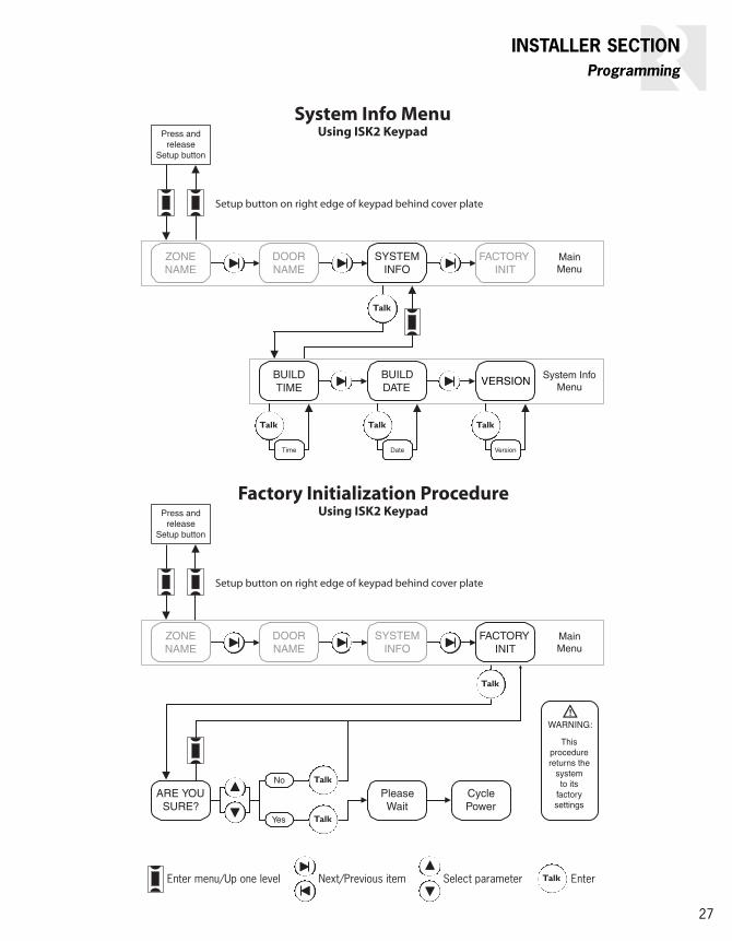
Viewing system information
The System Info Menu allows you to check thebuild time, build date, and version of the hub’sfirmware. This is useful to see whether the hubhas the latest firmware version. To view systeminformation, follow these steps (or the SystemInfo Menu flow chart on page 27):
1. Press and release the Setup button on the rightedge of the keypad to enter the main menu. Thedisplay shows ZName (ZONE NAME).
2. Press and release the Next or Previous key twice.They display shows SInfo (SYSTEM INFO).
3. Press the Talk key to enter the System Info menu.The display shows BTime (BUILD TIME).
4. Press and release the Talk key to view the buildtime, or
5. Press the Next key to go to BDate (BUILDDATE).
6. Press and release the Talk key to view the builddate, or
7. Press the Next key to go to Ver (VERSION).
8. Press and release the Talk key to view the version.
Press and release the Setup button once to exitthe procedure or twice to exit the main menu.
Restoring factory settings
The Factory Initialization Procedure resets thezone and door station label assignments andzone volume settings to the original factorydefaults. This procedure affects the hub towhich the keypad is connected, and initializinghub 1 also resets the entire system.
To restore the factory settings, follow thesesteps (or the Factory Initialization Procedureflow chart on page 27):
1. Press and release the Setup button on the rightedge of the keypad to enter the main menu. Thedisplay shows ZName (ZONE NAME).
2. Press and release the Next key three times or thePrevious key once. The display shows FInit (FACTORY INIT).
3. Press the Talk key to enter the Factory InitializationProcedure. The display shows Sure? (ARE YOUSURE?).
4. Press the Volume Up or Volume Down key toselect Yes.
5. Press the Talk key to initialize the system. The dis-play shows Please Wait, followed by CyclePower.
6. Cycle the power on the hub to which the keypad isconnected.

26
INSTALLER SECTIONProgramming
Press andrelease
Setup button
MainMenu
ZONENAME
ISK2 Keypad Zone Name Procedure
Setup button on right edge of keypad behind cover plate
DOORNAME
SYSTEMINFO
FACTORYINIT
Zn#? Name?
Press andrelease
Setup button
MainMenu
ISK2 Keypad Door Name Procedure
Setup button on right edge of keypad behind cover plate
Enter menu/Up one level Next/Previous item Select parameter Enter
ZONENAME
DOORNAME
SYSTEMINFO
FACTORYINIT
Dr#? Name?
27
INSTALLER SECTIONProgramming
Press andrelease
Setup button
MainMenu
Factory Initialization ProcedureUsing ISK2 Keypad
Setup button on right edge of keypad behind cover plate
ARE YOUSURE?
PleaseWait
Enter menu/Up one level Next/Previous item Select parameter Enter
Thisprocedurereturns the
systemto its
factorysettings
CyclePower
No
Yes
ZONENAME
DOORNAME
SYSTEMINFO
FACTORYINIT
Press andrelease
Setup button
MainMenu
System Info MenuUsing ISK2 Keypad
Setup button on right edge of keypad behind cover plate
System InfoMenu
BUILDTIME
BUILDDATE
VERSION
Time Date Version
ZONENAME
DOORNAME
SYSTEMINFO
FACTORYINIT

28
INSTALLER SECTIONSystem Functions
Detailed function descriptions
ComPoint routes communications by switchingits audio bus to the keypads and door stations.All switching takes place in the hub(s). The hubswitches the bus to either the microphone orthe amplifier in a keypad or door station, de-pending on the direction of the communication.
For example, when you start an intercom ses-sion, the system switches the bus to the micro-phone in the sending keypad and the keypadamplifier in the selected receiving zone. For thereply, it reverses the connection so the micro-phone in the receiving keypad is connected tothe amplifier in the sending keypad.
Communication priority levels
Certain communication events take priority overothers for proper system operation. Each func-tion has a priority level based on its application.If two identical levels of communication overlap,the first to occur has priority.
System functions have the following priorities:
Thus, paging is not allowed when the audio busis being used for an intercom session or a doorstation call. Similarly, an intercom session is notallowed when a door call or page is in progress.However, paging and intercom can interrupt Lis-ten mode, and door station calls can interruptall other communications. DND mode blocks alllevels of communication to a zone in that mode.
Paging
Paging is the default system function. To send apage, all one needs to do is press and hold theTalk key and speak, as long as the keypad isnot indicating a selected zone or door station.Since a page is a system-wide broadcast, nozone selection is necessary.
When a page is sent, the audio bus connects tothe microphone in the sending zone and theamplifiers in all other zones that are not in DNDmode. All keypads indicate which zone is send-ing the page for 30 seconds after the Talk keyin the sending zone is released.
During this 30-second time frame, anyone in areceiving zone can reply to the page by holdingin the Talk key and speaking. This switches theaudio bus to the microphone in the receivingzone and the amplifier in the sending zone. Thereply is heard only in the sending zone.
With paging, pressing the Talk key causes a single ping tone to sound in the receiving zonesto signal the beginning of the announcement.Releasing the Talk key sounds a double ping tosignal the end of the announcement.
Zones in DND mode don’t receive a page audiosignal but do indicate the sending zone. Also,pages are never sent to door stations.
Intercom
Intercom is a point-to-point communication thatinvolves only two zones, unlike a page which issystem wide. For ease of use, the intercomfunction allows hands-free replies as well asmanual replies with the Talk key.
Door station call Top priority (supersedes all other events)
PagingIntermediate priority
Intercom
Listen mode Low priority

29
INSTALLER SECTIONSystem Functions
The intercom function requires first selecting atarget zone. This is done by pressing a zonekey on the ISK1 Basic Keypad or scrolling to azone label on the ISK2 Advanced Keypad. Afterselecting a zone, the user may press the Talkkey to begin communication.
If an invalid zone (one that has no keypad) isselected on an ISK1 Basic Keypad, the zonekey blinks rapidly for 7 seconds. Pressinganother zone key selects another zone. After avalid target zone is selected, pressing the samezone key deselects it.
If a zone in DND mode is selected on an ISK1Basic Keypad, the zone key and DND key blinkrapidly for 7 seconds when the Talk key ispressed.
With the ISK2 Advanced Keypad, only validzones (ones with keypads connected) appear inthe zone list on the display. If a zone in DNDmode is selected, the display alternately showsthe zone label and DND at 1-second intervalsand the DND key blinks rapidly for 7 seconds. Aselected zone can be deselected by selectingPage or another zone.
When receiving an intercom message, the tar-get keypad indicates the sending zone. Thisindication remains for a 37-second reply periodafter the Talk key on the sending keypad isreleased.
There are two ways to reply to an intercommessage with either type of keypad: a hands-free reply within 7 seconds and using the Talkkey within 30 seconds thereafter. When the Talkkey on the sending keypad is released, both thesending and target keypads sound a single ping
and the target keypad permits a hands-freereply by activating its microphone for 7 sec-onds. During this period the Talk key on the tar-get keypad is lit red to indicate the microphoneis active.
After the 7 seconds, a double ping in both thesending and target zones indicates the end ofthe hands-free reply period. A reply may still bemade by pressing and holding the Talk key with-in the next 30 seconds. After the 30 seconds, areply can no longer be made, but a person inthe receiving zone can start a new intercomsession to the original sender.
Each time a Talk key in either zone is released,a single ping is heard in the other zone and the7- and 30-second reply periods are renewed.
Door station call
Communication with the door stations is similarto an intercom session, though there are signifi-cant differences. First, a door station has noability to select a target zone. Instead, it simplyrings the doorbell and a person in any zone canreply. Second, for privacy reasons the systemdoesn’t allow a hands-free reply to a door sta-tion call from the interior keypads. The replycan be made only by pressing and holding theTalk key.
When the Call key on a door station is pressed,each hub instructs all connected keypads thataren’t in DND mode to activate their speakerrelays and connects the audio bus to theiramplifiers. If a doorbell chime is selected onhub 1, the chime is played through the speakeroutputs on those keypads and through the inter-nal speakers in the door stations.
Intercom (cont’d)

30
INSTALLER SECTIONSystem Functions
Pressing the Call key also causes the doorbellcontacts to close for a minimum of 4 secondsto activate a separate doorbell or other deviceconnected to the door station. The actual timevaries with the doorbell selection on hub 1; thecontacts remain closed for the duration of theselected chime.
Also, all keypads indicate which door station iscalling, regardless of whether or not they’re inDND mode. The indication remains for 15 sec-onds, during which the door station is selectedat each keypad for reply.
Within the 15 seconds, a person at any keypadcan then speak with the person at the doorwhile holding in the Talk key. If the 15 secondspass before the Talk key is pressed, the personinside will need to first select the door stationon the keypad and then press the Talk key tostart a new session. This will not activate thedoorbell chime.
When a door call is answered from inside, therelease of the Talk key at the keypad triggers asingle ping at the door station to let the callerknow they can reply. The person at the doorstation has a 7-second window for a hands-freereply after the single ping. The caller has theoption of speaking within the 7 seconds orpressing and holding the Call key to speaklonger. Holding in the Call key keeps the audiobus switched to the door station’s microphone.
If the 7-second hands-free window ends beforethe caller presses the Call key to speak, thedoor station sounds a double ping indicating theaudio bus has opened. At this point the callermust press the Call key again to request anoth-er session if they wish to speak longer. Thisalso rings the doorbell again.
Door strike release
The optional ISDR1 Door Strike Release modulecan be activated from any keypad at any time.When activated, the module stays active for 3seconds, confirmed by a buzz tone at the key-pad and the door station.
On an ISK1 Basic Keypad, the module is activat-ed by pressing and holding the appropriate doorkey for 3 seconds.
When a communication session is activebetween a door station and an ISK2 AdvancedKeypad, the module can be activated by press-ing and holding both the Previous and Next keysfor 3 seconds. If no session is active, the doorwill first need to be selected on the keypad.
Listen mode
Listen mode is a system state in which one key-pad has a constantly active microphone andone or more other keypads are receiving itsaudio signal. This mode is subject to temporaryinterruption when the system is used for pag-ing, intercom, or door station sessions.
Selecting a keypad’s own zone connects itsmicrophone to the audio bus 2 seconds afterthe selection is made. That zone then becomesthe sending zone for Listen mode. The keypad’sTalk key lights up red to indicate the micro-phone is on. In addition, the zone key on anISK1 Basic Keypad blinks red and the display onan ISK2 Advanced Keypad shows MicOn.
If another zone is already selected as a sendingzone for Listen mode, the keys on the BasicKeypad for both the active zone and the desiredzone alternately blink red for 7 seconds to indi-cate which zone’s microphone is active. TheAdvanced Keypad alternately displays the activezone and MicOn for 7 seconds.
Door station call (cont’d)
31
INSTALLER SECTIONSystem Functions
Selecting the sending zone on other keypadsconnects their amplifiers to the audio bus sothey can listen to the sending zone.
Listen mode can be used with DND in the samezone as long as Listen mode is enabled first.
On either type of keypad, selecting a zone otherthan its own cancels Listen mode.
Because Listen mode is the lowest priority communication, it can be interrupted by otherfunctions, including an intercom session fromthe Listen mode sending keypad. When Listenmode is interrupted, the sending and receivingkeypads give a system busy indication until theinterruption is over.
If the audio bus is not available, attempting toactivate a keypad’s microphone for Listen modewill result in a system busy indication.
Audible keypad volume level indication
When the audio bus is inactive, pressing theVolume Up or Volume Down key on a keypadsounds a ping tone to audibly indicate the key-pad’s output level. As volume is increased theping tone gets louder and vice versa. Once thevolume adjustment reaches either end of therange, the ping tone no longer sounds.
System busy
If someone attempts to start a page or inter-com session when the system is busy, the Talkkey on the keypad blinks red for 7 seconds toindicate the system is unavailable. The ISK2Advanced Keypad display also flashes Busy atthe same time.
Do Not Disturb (DND) mode
Placing a zone in Do Not Disturb (DND) modeprevents the audio bus from being switched tothe keypad amplifier in that zone. Thus, thatzone will not receive any pages, intercom calls,door station calls, or doorbell chimes (unless aseparate doorbell is used). However, DND modewill not prevent the zone from receiving audiofrom a multiroom audio system.
The volume setting in effect when a zone is putin DND mode is retained when DND is canceld.
DND mode can be used in conjunction withListen mode as long as Listen mode is selectedfirst. If DND is selected first, pressing any keyto enable Listen mode will exit DND mode.
When a zone attempts an intercom session witha zone that is in DND mode, the DND key onthe sending keypad blinks red for 7 secondsafter the Talk key is pressed. Also, on the ISK1Basic Keypad, the zone key for the zone in DNDmode blinks red.
Keypad backlight
The keypad backlighting comes on wheneverany system function is activated and goes offafter 60 seconds of system inactivity.
Listen mode (cont’d)

32
INSTALLER SECTIONSystem test
System function test
Paging
Initiate a page from any keypad
• Verify all keypads indicate the sending zone
• Verify the page is heard in all zones
Reply to a page from a receiving zone
• Verify communication with sending zone
Intercom
Initiate an intercom session
• Verify the receiving zone keypad indicatesthe sending zone
• Verify the message is heard in the receivingzone
Reply to initial message
• Verify hands-free operation within 7 seconds
• Verify reply with Talk key after 7 seconds
• Verify reply is heard in sending zone
Door station call
Initiate a door station call
• Verify all keypads indicate the door station
• Verify door chime (if selected)
Reply to door station call
• Verify reply is heard at door station
Answer reply from door station
• Verify hands-free operation within 7 seconds
• Verify operation with Call key after 7 seconds
• Verify answer is heard in replying zone
Door strike release
Initiate a door strike release
• Verify module activation
• Verify audible confirmation
Listen mode
Activate microphone in zone to be heard
• Verify keypad confirmation of microphone on
Select zone to be heard at another keypad
• Verify keypad indication of selected zone
• Verify audio transmission from zone withactive microphone
Cancel Listen mode
• Verify clearing of Listen mode
Do Not Disturb mode
Enable DND mode on a keypad
• Verify no interruption by paging, intercom, ordoorbell
• Verify DND indication on another keypadattempting to intercom to keypad in DNDmode
Cancel DND mode on a keypad
• Verify clearing of DND mode

33
INSTALLER SECTIONTroubleshooting
Troubleshooting chart
Symptom Possible Cause What to DoTalk key flashes rapidly; AdvancedKeypad indicates WrongConnection shortly after poweringsystem
Keypad connected to door station port ordoor station connected to keypad port onhub
Check keypad and door station connections at hub
Door station connected to a hub otherthan hub 1
Check door station connections at hub
Hub ID numbers not assigned Assign a unique ID number for each hub
No response or backlight at any keypad
No power to hub(s) Make sure a power supply is plugged intoeach hub and the AC circuit is energized
No response or backlight at onekeypad; others work OK
Open power or ground wire in CAT-5 cableor bad termination
Check orange pair and terminations
Programming jumper is shorting 2 pins onright edge of second circuit board
Remove programming jumper
Faulty port on hub Power down, swap connector to another port,power up; if keypad works OK, replace hub
No port indication on AdvancedKeypad display when powering up
Open status wire in CAT-5 cable or badtermination
Check green wire and terminations
Keypad lights up but doesn’t work;Advanced Keypad indicates onlyPage and initial volume
Open communication wire in CAT-5 cableor bad termination
Check blue pair and terminations
Keypad failed to register with hub(other keypads don’t indicate thiskeypad’s zone)
Open communication wire in CAT-5 cableor bad termination
Check blue pair and terminations
Keypad was connected to hub while system was powered
Cycle power to hub(s) and wait 15 secondsbefore using keypads
No communication audio in onezone; speakers play music OK
Room speakers not properly connected tokeypad
Make sure speakers are connected to keypadoutput connector
Open audio wire in CAT-5 cable or bad termination
Check brown pair and terminations
Popping sound occurs before andafter ping tone when Talk key isused or volume is adjusted
System has a bad keypad Disconnect one keypad at a time until poppingsound stops; replace keypad and cycle power
No doorbell chime Chime not selected at hub Select chime tone(s) on hub 1
Doorbell chime too loud/soft overall Doorbell chime gain not adjusted Adjust doorbell chime gain on hub 1
Doorbell chime too loud/soft insome zones, OK in others
Doorbell chime volume set to variable leveland keypads set to different volume levels
Set doorbell chime volume switch to fixedlevel (1)
Adjust keypad volume settings
Door strike release module doesn’toperate
Open trigger wire in CAT-5 cable or badtermination
Check green/white wire and terminations
Assigned zone labels appear onsome Advanced Keypads but notothers
Multiple hubs not linked together Link hubs and cycle power
Hub 1 powered up too early (before otherhubs)
Cycle power on hub 1 last

34
REFERENCE SECTIONTechnical Specifications
SystemMaximum zones: 36 (up to 6 hubs)
Door stations: 2 maximumCommunications cable: CAT-5/CAT-5eMaximum cable length: 250 feet (76 m)
ISK1 Basic KeypadUser controls: 6 zone selection/indication keys
Talk key2 door selection/indication keysDND selection/indication keyVolume Up and Volume Down keys
Key backlighting: Installer-selectable amber or green, with red indication
Audio input: Built-in microphone with automatic gain control
Amplifier: Monaural (for system functions only)Amplifier power: 2 watts
Min. load impedance: 6 ohms per channelSpeaker relay: 4-pole double-throw
Speaker relay rating: 50 watts RMS continuousSpeaker connector: 8-pole screw terminalSpeaker wire size: Up to 14 AWG (1.63 mm)CAT-5 connector: 110 punch-down block
Power consumption: 15 VDC 800 mA maximum, 200 mA typical
Keypad style: Single-gang Decora®
Dimensions: 1.875” W x 4.188” H x 2.5” D(4.8 x 10.6 x 6.4 cm)
Weight: 4.8 oz (136 g)
ISK2 Advanced KeypadDisplay: 5-character backlit LCD panel
User controls: Talk keyNext and Previous keysDND selection/indication keyVolume Up and Volume Down keys
Backlighting: Installer-selectable amber or green, with red indication
Audio input: Built-in microphone with automatic gain control
Amplifier: Monaural (for system functions only)Amplifier power: 2 watts
Min. load impedance: 6 ohms per channelSpeaker relay: 4-pole double-throw
Speaker relay rating: 50 watts RMS continuousSpeaker connector: 8-pole screw terminalSpeaker wire size: Up to 14 AWG (1.63 mm)CAT-5 connector: 110 punch-down block
Power consumption: 15 VDC 800 mA maximum, 200 mA typical
Keypad style: Single-gang Decora®
Dimensions: 1.875” W x 4.188” H x 2.625” D(4.8 x 10.6 x 6.7 cm)
Weight: 5.6 oz (159 g)
ISK3 Door StationUser control: Call key with amber backlightAudio input: Built-in microphone with automatic gain
controlAmplifier: Monaural (for system functions only)
Amplifier power: 2 wattsVolume control: Installer-adjustable potentiometer
Audio output: Built-in speakerCover plate: Weatherproof plated die-cast zinc
CAT-5 connector: 110 punch-down blockDoorbell connector: 2-pole screw terminalDoorbell wire size: Up to 18 AWG (1.024 mm)Doorbell contact: 1 A @ 12 VDC
Power consumption: 15 VDC 220 mA maximumDimensions: 3” W x 5.125” H x 3.25” D
(7.6 x 13.0 x 8.3 cm)Dimensions in wall box: 2” W x 2.875” H x 2.75” D
(5.1 x 7.3 x 7.0 cm)Wall box required: Single-gang, 22 cu in (360 cm3) min
Weight: 8 oz (227 g)
ISH1 HubKeypad ports: (6) 8-pole modular RJ-45
Door station ports: (2) 8-pole modular RJ-45Link ports: (2) 8-pole modular RJ-45
Firmware update port: 4-pole port for Programming Cable,Russound part #2500-521065
Switches: 4-switch DIP for hub ID setting8-switch DIP for 2 doorbell settingsPotentiometer for doorbell volume
Doorbell options: 7 chime patterns plus no chimePower requirement: 15 VDC 3.5 A (uses ISPS power supply)
Mounting method: Surface or structured wiring panelDimensions: 6.438” W x 5.125” H x 1.813” D
(16.4 x 13.0 x 4.6 cm)Weight: 25.6 oz (0.73 kg)
ISDR1 Door Strike Release ModuleCAT-5 connectors: (2) 110 punch-down blocks
Strike release relay: 1-pole double-throw (NC/NO)Relay connector: Removable 3-pole screw terminalRelay wire size: Up to 14 AWG (1.63 mm)
Relay contact rating: 5 A @ 12 VDCMounting method: Surface
Dimensions: 3” W x 1.875” H x 1” D(7.6 x 4.8 x 2.5 cm)
Weight: 4.8 oz (136 g)
ISSP SpeakerDevice style: Single-gang Decora®
Connection: Attached wire leadsPower rating: 2 watts nominal, 5 watts maximum
Impedance: 8 ohmsDimensions: 1.65” W x 4.13” H x 1.42” D
(4.2 x 10.5 x 3.6 cm)Weight: 3 oz (85 g)

35
REFERENCE SECTIONWarranty
WarrantyThe Russound ComPoint system components (ISH1, ISK1, ISK2, ISK3, ISDR1, and ISSP) are fully guaranteed for two (2) yearsfrom the date of purchase against all defects in materials and workmanship. For this warranty to apply, the components mustbe installed and used according to their written instructions. During this period, Russound will replace any defective parts andcorrect any defect in workmanship without charge for either parts or labor. Accidental damage and shipping damage are notconsidered defects under the terms of this warranty. Russound assumes no responsibility for defects resulting from abuse orservicing performed by an agency or person not specifically authorized in writing by Russound. If service is necessary, it mustbe performed by Russound. Damage to or destruction of components due to excessive power voids the warranty. In thesecases, the repair will be made at the owner’s expense. To return a product for repairs, the unit must be shipped to Russoundat the owner’s expense, along with a note explaining the nature of the service required. Be sure to pack in a corrugated con-tainer with at least 3 inches of resilient material to protect the unit from damage in transit.
Before returning a unit for repair, call Russound at 603.659.5170 for a Return Authorization number. Write the RA number onthe shipping label and ship to: Russound, 5 Forbes Road, Newmarket NH 03857.
Russound sells products only through authorized dealers and distributors to ensure that customers obtain proper support andservice. Any Russound product purchased from an unauthorized dealer or other source, including retailers, mail order sellersand online sellers will not be honored or serviced under existing Russound warranty policy. Any sale of products by an unau-thorized source or other manner not authorized by Russound shall void the warranty on the applicable product.

28-1211 Revision 1 08/23/06
Russound5 Forbes Road, Newmarket NH 03857 USATel 603.659.5170 • Fax 603.659.5388www.russound.comTechnical Support: [email protected]
ComPointThe music lover’s intercom solution
Instruction Manual
ModelsISH1ISK1ISK2ISK3ISDR1ISSP
Copyright © 2006 Russound. All rights reserved. All trademarks are the property of their respective owners. Specifications aresubject to change without notice. Russound is not responsible for typographical errors or omissions.


