Embed Size (px)
Citation preview

RollerRoller
CATALOG No.270-11E
Caged Roller LM GuideRoller Cage EffectUltra-super-highRigidity SRG/SRN
Compliant withNew Accuracy Standards
For details, visit THK at www.thk.com*Product information is updated regularly on the THK website.
906-0769_H1-4_P01.4C(C95M40) 09.8.5 9:57 AM ページ h1

1
According to the history of rotary ball bearings, which used balls as the rolling elements, their earlyforms were full-ball types without ball cages. Therefore, friction between balls caused loud noise, made high-speed rotation impossible andshortened the service life.Twenty years later, a Caged Ball design was developed for ball bearings. The new design enabled high-speed rotation at a low noise level, and extended the service life despite a reduced number of ballsused. It marked a major development of ball bearings. Similarly, the performance of needle bearings using rollers was significantly improved by the cagedroller structure, as represented in the history of bearings. The Cage Roller LM Guide has a structure thatdoes not cause friction between rollers and allows grease to be retained in a grease pocket between adjacentrollers, thus ensuring long-term maintenance-free operation.
History of the Rotary Ball Bearing
With the Caged Roller LM Guide, the use of a roller cageallows lines of evenly spaced rollers to circulate, thus toreduce fluctuations in rolling resistance and achievesmooth and stable motion. In addition, grease held in aspace between the roller circulation path and the rollercage (grease pocket) is applied on the contact surfacebetween each roller and the roller cage as the rollerrotates, forming an oil film on the roller surface. Thisminimizes the risk of oil-film break.
Conventional Structure Caged Roller Structure
Caged Roller LM Guide
Use of a roller cage eliminatesfriction between rollers
Oil-film contact
Conventional Structure●Adjacent balls make point contact
each other. As a result, unitsurface pressure is high, the oilfilm easily breaks, and wear occursdue to friction.●The service life becomes shorter.
Caged Ball Structure●The service life is prolonged due to the elimination of wear caused
by friction between balls.●The absence of friction between balls results in reduced heat
generation during high-speed rotation.●The absence of friction between balls eliminates collision noise of
the balls.●Even spacing of the balls enables them to move smoothly.●Retention of lubricant in the ball cage ensures a long service life.
Friction between rollers
Roller
Roller Cage Effect
Long Service Life, Long-termMaintenance-free Operation
High-Speed Operation
Low Noise, Acceptable Running Sound
Smooth Motion
Low Dust Generation
906-0769_H1-4_P01.4C(C95M40) 09.8.5 9:57 AM ページ 1

2
Cross section
LM block
LM rail
End plate
End seal
Roller cage
Roller
45°
45°
45°
45°
Ultra-super-high Rigidity Caged Roller LM Guide SRG/SRN
Structure of Model SRG
Models SRG and SRN are ultra-super-high rigidity Roller Guides that use roller cages to allow low-friction, smooth motion and achieve long-term maintenance-free operation.
● Ultra-super-high RigidityThey achieve remarkably high rigidity by using rollers,which are less subject to deformation, for the rollingelements and having the overall roller length 1.5 timesgreater than the roller diameter.
● 4-way Equal LoadEach row of balls is placed at a contact angle of 45°so thatthe rated loads applied to the LM block are uniform in thefour directions (radial, reverse radial and lateral directions),ensuring high rigidity in any direction.
● Long-term maintenance-freeoperation
Use of roller cages eliminates friction between rollers andincreases grease retention, enabling long-termmaintenance-free operation to be achieved.
● Global Standard SizeSRG and SRN are designed to have dimensions almost the sameas that of the full-ball type LM Guide model HSR, which THK as apioneer of the linear motion system has developed and is a defacto global standard model.
906-0769_P02-06.2C(DIC2591) 09.8.5 9:58 AM ページ 2

3
0
2
4
6
8
10
12
0 5 10 15 20 25 30
Conventional roller guide #45
SRG45LC(with a caged roller)
Radial load (kN)D
efle
ctio
n(μ
m)
0
5
10
15
20
0 5 10 15 20 25 30
Conventional roller guide #45
Reverse-radial load (kN)
Def
lect
ion(μ
m)
SRG45LC(with a caged roller)
Table bolt fixed Bolt not fixed(free)
Horizontal load (kN)
0
10
20
30
40
0 5 10 15 20 25 30
#45
Def
lect
ion(μ
m)
SRG45LC(with a caged roller)
Conventional roller guide
[Magnitude of the preload]SRG: radial clearance C0Conventional type: equivalent to radical clearance C0
Radial rigidityRadial rigidity
Reverse-radial rigidity
Horizontal rigidity
Reverse-radial rigidity
Horizontal rigidity
Place two rails in parallel to each other so that amoment is not applied, and measure the rigiditywith one rail not fixed with bolts.
● High Rigidity Evaluation DataRemarkably high rigidity is achieved by using rollers, which are less subject to deformation, for the rolling elements andhaving the overall roller length 1.5 times greater than the roller diameter.
906-0769_P02-06.2C(DIC2591) 09.8.5 9:58 AM ページ 3
4
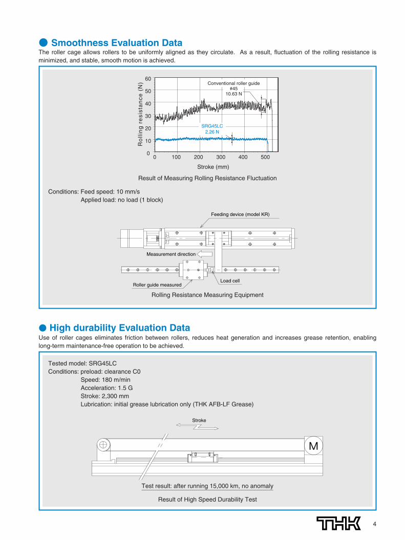
● Smoothness Evaluation DataThe roller cage allows rollers to be uniformly aligned as they circulate. As a result, fluctuation of the rolling resistance isminimized, and stable, smooth motion is achieved.
Feeding device (model KR)
Roller guide measuredLoad cell
Measurement direction
Conditions: Feed speed: 10 mm/sApplied load: no load (1 block)
0
10
20
30
40
50
60
0 100 200 300 400 500
Stroke (mm)
Ro
llin
g r
esi
sta
nce
(N
)
SRG45LC2.26 N
Conventional roller guide#45
10.63 N
Result of Measuring Rolling Resistance Fluctuation
Rolling Resistance Measuring Equipment
Stroke
M
Test result: after running 15,000 km, no anomaly
Tested model: SRG45LCConditions: preload: clearance C0
Speed: 180 m/minAcceleration: 1.5 GStroke: 2,300 mmLubrication: initial grease lubrication only (THK AFB-LF Grease)
● High durability Evaluation DataUse of roller cages eliminates friction between rollers, reduces heat generation and increases grease retention, enablinglong-term maintenance-free operation to be achieved.
Result of High Speed Durability Test
906-0769_P02-06.2C(DIC2591) 09.8.5 9:58 AM ページ 4

55
●SRG 25C ●SRG 45C●SRG 30C ●SRG 55C●SRG 35C
SRG/SRN OutlineModels SRG/SRN - Product Overview
●SRG 15A ●SRG 20A
●SRG 20LA
L
ModelSRG-A
ModelSRG-LA
The LM block has the same sectionalshape as model SRG-A, but has alonger overall LM block length (L) anda greater rated load.
The flange of the LM block has tappedholes. Can be mounted from the top.
ModelSRG-C
The flange of the LM block has tappedholes. Can be mounted from the top orbottom. Used in placed where thetable cannot have through holes formounting bolts.
Having almost the same dimensions as the de facto standard, full-ball type LM Guide model HSR, thesemodels are superbly capable of receiving an ultra-super heavy load and optimal for machine tools.Major applications machining center / NC lathe / grinding machine / five axis milling machine / drilling
machine / NC milling machine / semiconductor manufacturing machine / moldingmachine
906-0769_P02-06.2C(DIC2591) 09.8.5 9:58 AM ページ 5

6
SRG/SRN OUTLINEModels SRG/SRN-Product Overview
●SRG 25R ●SRG 45R●SRG 30R ●SRG 55R●SRG 35R
●SRG 25LR ●SRG 45LR●SRG 30LR ●SRG 55LR●SRG 35LR
●SRG 15V ●SRG 20V
●SRG 20LV ●SRG 65LV
●SRG 25LC ●SRG 45LC●SRG 30LC ●SRG 55LC●SRG 35LC ●SRG 65LC
L
W
W
L
L
ModelSRG-LC
The LM block has the same sectionalshape as model SRG-C, but has alonger overall LM block length (L) anda greater rated load.
ModelSRG-R
The LM block has a smaller width (W)and is equipped with tapped holes.Used in places where space for tablewidth is limited.
ModelSRG-LR
The LM block has the same sectionalshape as model SRG-R, but has alonger overall LM block length (L) anda greater rated load.
ModelSRG-V
The LM block has a smaller width (W)and is equipped with tapped holes.Used in places where space for tablewidth is limited.
ModelSRG-LV
The LM block has the same sectionalshape as model SRG-V, but has alonger overall LM block length (L) anda greater rated load.
906-0769_P02-06.2C(DIC2591) 09.8.5 9:58 AM ページ 6

7
PE :Equivalent load (N)⋅Radial direction⋅Reverse-radial direction⋅Lateral direction
PR :Radial load (N)PL :Reverse-radial load (N)PT :Lateral load (N)
PE=PR(PL)+PT
Rated Loads in All Directions
Equivalent Load
Models SRG/SRN are capable of receivingloads in all four directions: radial, reverse-radial and lateral directions.
The basic load ratings are uniform in the fourdirections (radial, reverse-radial and lateraldirections), and their actual values are provided inthe dimensional table*1 for models SRG/SRN.
When the LM block of models SRG/SRNreceives loads in all directionssimultaneously, the equivalent load isobtained from the equation below.
PT
PRPL
PT
Radial directionReverse-radial direction
Lateral direction
Lateral direction
Build-to-order Models
Model SRN-LR
Model SRN-C
●SRN 35LR●SRN 45LR●SRN 55LR●SRN 65LR
●SRN 35C●SRN 45C●SRN 55C
Model SRN-LC
●SRN 35LC●SRN 45LC●SRN 55LC●SRN 65LC
L
Model SRN-R
●SRN 35R●SRN 45R●SRN 55R
W
L
7
The flange of the LM block has tapped holes.Can be mounted from the top or bottom. Used in placed where the table cannot have through holesfor mounting bolts.
*1: Models SRG/SRNdimensional tables
Model SRG-A/LA/C/LC:starting on P. 13
Model SRG-V/LV/R/LR:starting on P. 15
Model SRN-C/LC:starting on P. 17
Model SRN-R/LR:starting on P. 17
The LM block has the same sectional shape as modelSRN-C, but has a longer overall LM block length (L) and agreater rated load.
The LM block has a smaller width (W) and is equipped withtapped holes. Used in places where space for table width is limited.
The LM block has the same sectional shape as modelSRN-R, but has a longer overall LM block length (L) and agreater rated load.
906-0769_P07-18.2C(DIC2591) 09.8.5 9:59 AM ページ 7

88
SRG/SRN OUTLINEModels SRG/SRN - Product Overview
CPC
fH · fT · fC
fWL = ( · )3 100
10
Lh =L 106
2 RS n1 60
The service life of an LM Guide is subject to slight variations even if multiple unitsof the identical model manufactured in the same process are used under the sameoperational conditions. Therefore, it is necessary to use the nominal life definedbelow as a reference value for obtaining the service life of the LM Guide.
1.0
0.9
0.8
0.7
0.6
0.5
0.4
0.3
0.2
0.1
60 50 40 30 20 10Raceway hardness (HRC)
Har
dn
ess
fact
or
fH
Fig. 1
■fH:Hardness factorTo ensure the achievement of the optimum load capacity of the LM Guide,the raceway hardness must be between 58 and 64 HRC.At hardness below this range, the basic dynamic and static load ratingsdecrease. Therefore, the rating values must be multiplied by therespective hardness factors (fH).Since the LM Guide has sufficient hardness, the fH value for the LM Guideis normally 1.0.
■fC:Contact factorWhen multiple LM blocks are used in close contact with each other, it isdifficult to achieve uniform load distribution due to moment loads andmounting-surface accuracy. When using multiple blocks in close contactwith each other, multiply the basic load rating (C or C0) by thecorresponding contact factor indicated in Table 1.Note: When uneven load distribution is expected in a large machine, consider using a contact
factor from Table 1.
■fT:Temperature factorSince the service temperature of a Caged Roller LM Guide is normally80℃ or below, the temperature factor fT is 1.0.
■fW:Load factorIn general, reciprocating machines tend to produce vibrations or impactduring operation. Additionally, it is especially difficult to accuratelydetermine all vibrations generated during high-speed operation andimpacts produced each time the machine starts and stops. Therefore, where the effects of speed and vibration are estimated to besignificant, divide the basic dynamic load rating (C) by a load factorselected from Table 2, which contains empirically obtained data.
●Nominal LifeThe nominal l i fe means the total traveldistance that 90% of a group of the same LMGuide model can achieve without flaking(scale-like exfoliation on the metal surface)after individually running under the sameconditions.
●Service Life TimeOnce the nominal life (L) has been obtained,the service life time can be obtained using theequation on the right if the stroke length andthe number of reciprocations are constant.
L : Nominal life (km)C : Basic dynamic load rating*1 (N)PC : Calculated load (N)fH : Hardness factor (see Fig. 1)fT : Temperature factorfC : Contact factor (see Table 1)fW : Load factor (see Table 2)
Lh : Service life time (h)Rs : Stroke length (mm)n1 : No. of reciprocations per min (min-1)
Table 1 Contact Factor (fC)
Table 2 Load Factor(fW)
Number of blocks used in close contact
2
3
4
5
6 or greater
Normal use
Contact factor fC
0.81
0.72
0.66
0.61
0.6
1
Faint
Weak
Medium
Strong
Very slowV≦0.25m/s
Slow0.25<V≦1m/s
Medium1<V≦2m/s
FastV>2m/s
1 to 1.2
1.2 to 1.5
1.5 to 2
2 to 3.5
Vibration/impact Speed (V) fW
*1: Basic dynamic load rating(C)
The basic dynamic loadrating (C) indicates the loadwith constant direction andmagnitude, under which therated life (L) is L = 50 kmfor an LM system usingballs, or L = 100 km for anLM system using rollers,when a group of identicalLM system independentlyoperating under the sameconditions.
Service Life
906-0769_P07-18.2C(DIC2591) 09.8.5 9:59 AM ページ 8

9
Radial clearance
9
*1: Preload
Preload is an internal loadapplied to the roll ingelements (roller) in advancein order to increase therigidity of the LM block. Theclearances of all SRG/SRNmodels are adjusted tospecified values beforeshipment, and therefore it isunnecessary to adjust theirpreloads.
Radial Clearance StandardSince the radial clearance of an LM Guidegreatly affects the running accuracy, loadcarrying capacity and rigidity of the LMGuide, it is important to select anappropriate clearance according to theapplication.
In general, selecting a negative clearance (i.e., apreload*1 is applied) while taking into accountpossible vibrations and impact generated fromreciprocating motion favorably affects the servicelife and the accuracy.
15
20
25
30
35
45
55
65
– 0.5 to – 0 – 1 to – 0.5 – 2 to – 1
– 0.8 to – 0 – 2 to – 0.8 – 3 to – 2
– 2.0 to – 1 – 3 to – 2.0 – 4 to – 3
– 2.0 to – 1 – 3 to – 2.0 – 4 to – 3
– 2.0 to – 1 – 3 to – 2.0 – 5 to – 3
– 2.0 to – 1 – 3 to – 2.0 – 5 to – 3
– 2.0 to – 1 – 4 to – 2.0 – 6 to – 4
– 3.0 to – 1 – 5 to – 3.0 – 8 to – 5
Unit: μmRadial clearance of models SRG/SRN
Indication symbol Normal Light preload Medium preload
Model No. No symbol C1 C0
906-0769_P07-18.2C(DIC2591) 09.8.5 9:59 AM ページ 9

10
*2: Running parallelism
It refers to a parallelismerror between the LM blockand the LM rail datum planewhen the LM block travelsthe whole length of the LMrail, which is secured on thereference datum planeusing bolts.
*3: Difference in height M
It indicates a differencebetween the minimum andmaximum values in height(M) of each of the LMblocks used on the sameplane in combination.
*4: Difference in width W2
It indicates a differencebetween the minimum andmaximum values in width(W2) between each of theLM blocks, mounted on oneLM rail in combination, andthe LM rail.
Model No.Accuracy standard
ItemPrecision grade
PSuper precision grade
SPUltra precision grade
UPDimensional tolerance for height MDifference in height MDimensional tolerance for width W2
Difference in width W2
Running parallelism of surface Ç against surface ÅRunning parallelism of surface Îagainst surface ıDimensional tolerance for height MDifference in height MDimensional tolerance for width W2
Difference in width W2
Running parallelism of surface Çagainst surface ÅRunning parallelism of surface Îagainst surface ıDimensional tolerance for height MDifference in height MDimensional tolerance for width W2
Difference in width W2
Running parallelism of surface Çagainst surface ÅRunning parallelism of surface Îagainst surface ı
Dimensional tolerance for height MDifference in height MDimensional tolerance for width W2
Difference in width W2
Running parallelism of surface Çagainst surface ÅRunning parallelism of surface Îagainst surface ı
as shown in the table below
as shown in the table below
as shown in the table below
as shown in the table below
as shown in the table below
as shown in the table below
as shown in the table below
as shown in the table below
0.006
0.006
0– 0.03
0– 0.02
0.007
0.007
0– 0.04
0– 0.03
0.007
0.007
0– 0.05
0– 0.04
0.01
0.01
0– 0.05
0– 0.05
0.004
0.004
0– 0.015
0– 0.015
0.005
0.005
0– 0.02
0– 0.015
0.005
0.005
0– 0.03
0– 0.025
0.007
0.007
0– 0.04
0– 0.04
0.003
0.003
0– 0.008
0– 0.008
0.003
0.003
0– 0.01
0– 0.01
0.003
0.003
0– 0.015
0– 0.015
0.005
0.005
0– 0.03
0– 0.03
1520
253035
65
4555
Accuracies of models SRG/SRN are categorizedinto Precision grade (P), Super precision grade (SP)and Ultra precision grade (UP) as indicated in thetable below.
Accuracy StandardAccuracies of models SRG/SRN arespecified in terms of running parallelism*2,dimensional tolerance for height and width,and height and width difference between apair*3,*4 when 2 or more LM blocks are usedon one rail or when 2 or more rails aremounted on the same plane.
W2
M
A
D
C
B
10
SRG/SRN OUTLINEModels SRG/SRN - Product Overview
LM rail length (mm) Running Parallelism Values
Above Or lessPrecision grade Super precision grade Ultra precision grade
P SP UP― 50 12 11.5 1150 80 12 11.5 1180 125 12 11.5 11
125 200 12 11.5 11200 250 12.5 11.5 11250 315 13 11.5 11315 400 13.5 12 11.5400 500 14.5 12.5 11.5500 630 15 13 12630 800 16 13.5 12800 1000 16.5 14 12.5
1000 1250 17.5 14.5 131250 1600 18 15 141600 2000 18.5 15.5 14.52000 2500 19.5 16 152500 3090 11 16.5 15.5
LM Rail Length and Running Parallelism for Models SRG/SRN Unit: μm
Unit: mm
906-0769_P07-18.2C(DIC2591) 09.8.5 9:59 AM ページ 10

1111
Normally, the mounting base for the LM rail and the LM block has a datum planeon the side face of the shoulder of the base in order to allow easy installation andhighly accurate positioning.
The corner of the mounting shoulder must be machined to have a recess, or machined to besmaller than the corner radius, to prevent interference with the chamfer of the LM rail or the LMblock.
Shoulder Height of the Mounting Base and the Corner Radius
Unit: mm
15
20
25
30
35
45
55
65
0.5
0.5
1.0
1.0
1.0
1.5
1.5
1.5
0.5
0.5
1.0
1.0
1.0
1.5
1.5
2.0
2.5
3.5
4.0
4.5
5.0
6.0
8.0
9.0
04.0
05.0
05.0
05.0
06.0
08.0
10.0
10.0
04.0
04.6
04.5
05.0
06.0
08.0
10.0
11.5
r2
r2
H2
r1
r1H1
H3
■Model SRG
Unit: mm
35
45
55
65
1.0
1.5
1.5
1.5
1.0
1.5
1.5
2.0
5
6
8
8
06
08
10
10
06
07
10
10
■Model SRN
Model No.Corner radius for
the LM rail r1 (max)
Shoulder height for the LM rail
H1
Shoulder height for the LM block
H2 H3
Corner radius for the LM block
r2 (max)
Model No.Corner radius for
the LM rail r1 (max)
Shoulder height for the LM rail
H1
Shoulder height for the LM block
H2 H3
Corner radius for the LM block
r2 (max)
906-0769_P07-18.2C(DIC2591) 09.8.5 9:59 AM ページ 11

SRG/SRN OUTLINEModels SRG/SRN - Product Overview
1212
Error Allowance on the Mounting SurfaceWith Caged Roller LM Guide models SRG/SRN, the rollers serving as the rollingelements ensure high rigidity and the roller retainer prevents rollers from skewing.However, the mounting surface needs to be machined with high precision. A largeaccuracy error of the mounting surface affects the rolling resistance and theservice life. The following shows the maximum error allowance (limit value) of themounting surface according to the radial clearance.
Permissible error on the mounting surface 0.000036b
Unit: mm
b
Y
Tole
ranc
efo
r pa
ralle
lism
P
SRG 15
SRG 20
SRG 25
SRG 30
SRG/SRN 35
SRG/SRN 45
SRG/SRN 55
SRG/SRN 65
Unit: mm
Error Allowance in Level (Y) in the Axial Direction
Error Allowance in Parallelism (P) between Two Rails
X2
a
X1
Radial clearanceError allowance on the mounting surface (X)
Normal C1 C0
0.00030a 0.00021a 0.00011a
Unit: mm
X=X1+X2 X1: Level difference on the rail mounting surfaceX2: Level difference on the block mounting surface
Example of calculationWhen the rail span: a = 500 mmError allowance on the mounting surface:X = 0.0003×500
= 0.15
Error Allowance in Vertical Level (X) between Two Rails
Radial clearanceNormal C1 C0
Model No.0.005 0.003 0.003
0.008 0.006 0.004
0.009 0.007 0.005
0.011 0.008 0.006
0.014 0.010 0.007
0.017 0.013 0.009
0.021 0.014 0.011
0.027 0.018 0.014
906-0769_P07-18.2C(DIC2591) 09.8.5 9:59 AM ページ 12

SRG 15A
SRG 20ASRG 20LASRG 25CSRG 25LCSRG 30CSRG 30LCSRG 35CSRG 35LCSRG 45CSRG 45LCSRG 55CSRG 55LC
SRG 65LC
24
30
36
42
48
60
70
90
47
63
70
90
100
120
140
170
69.2
86.2106.2
95.5115.1111135125155155190185235
303
B
38
53
57
72
82
100
116
142
C
30
40
45
52
62
80
95
110
C2
26
35
40
44
52
60
70
82
S
M 5
M 6
M 8
M10
M10
M12
M14
M16
R1
8
10
-
-
-
-
-
-
R2
7.5
9.0
-
-
-
-
-
-
H
-
-
6.8
8.5
8.5
10.5
12.5
14.5
L1
45
587865.585.1759982.2
112.2107142129.2179.2
229.8
T
7
10
9.5
12
11.5
14.5
17.5
19.5
T1
-
-
10
14
10
15
18
20
K
20
25.4
31.5
37
42
52
60
78.5
N
4
5
5.5
6.5
6.5
10
12
17
E
4.5
4.5
12
12
12
16
16
16
e0
4
4
6
6
6
7
9
9
f0
6
6
6.4
6.2
6
7
8.5
13.5
D0
2.9
2.9
5.2
5.2
5.2
5.2
5.2
5.2
H3
4
4.6
4.5
5
6
8
10
11.5
PB107
PB107
B-M6F
B-M6F
B-M6F
B-PT1/8
B-PT1/8
B-PT1/8
13
Models SRG-A/SRG-LA SRG-C/SRG-LCDimensional Table for Models SRG-A/SRG-LA and Models SRG-C/SRG-LC
MB
F
N
M1h
φd1
φd2L1L
C4-S×R1
B
2-S×R2C2
(E) e0
f0
4-φD0*1W
T
M
W1W2
(K)
H3
MC MA
Models SRG15 and 20A/LA
13
Model No.
Outer dimensions LM block dimensions
Width
W
Length
L
Grease
nipple
Height
M
■ Example of model numbercoding
zModel number xType of LM block cNo. of LM blocks used on the same rail vWith QZ Lubricator attached bSymbol for contamination protection
accessory (see page 22) nRadial clearance symbol (see page 9) mLM rail length (in mm) ,Accuracy symbol (page 10) .Symbol for joint LM rail ⁄0No.
of LM rails used on the same plane
SRG45 LC 2 QZ KKHH C0 +1200L P T -Ⅱz , . ⁄0mnbvx c
Note This model number indicates that a single-rail unit constitutes one set (i.e., required number of sets when 2 rails are used inparallel is 2 at a minimum).Those models attached with QZ Lubricator cannot have a grease nipple.
906-0769_P07-18.2C(DIC2591) 09.8.5 9:59 AM ページ 13

15
20
23
28
34
45
53
63
16.0
21.5
23.5
31.0
33.0
37.5
43.5
53.5
15.5
20
23
26
30
37
43
54
30.0
30.0
30.0
40.0
40.0
52.5
60.0
75.0
2500
3000
3000
3000
3000
3090
3060
3000
4.5×7.5×5.3
6×9.5×8.5
7×11×9
9×14×12
9×14×12
14×20×17
16×23×20
18×26×22
11.3
2126.727.934.239.348.359.17691.9
115131167
278
25.8
46.963.857.57582.5
108119165192256266366
599
0.21
0.480.880.6411.071.021.761.663.133.496.135.82
10.8
22.7
1.24
2.744.493.75.746.219.73
10.1172032.23357
120
0.21
0.480.880.6411.071.021.761.663.133.496.135.82
10.8
22.7
1.24
2.744.493.75.746.219.73
10.1172032.23357
120
0.24
0.580.790.7951.031.471.922.393.314.986.648.19
11.2
22.1
0.20
0.420.570.70.91.21.61.92.43.74.55.97.8
16.4
1.58
2.58
3.6
4.4
6.9
11.6
15.8
23.7
Unit: mm
14
MB
6-S(φH through)
C2
L1
C
L(E)e0
f0φd2
φd1
M1
F
h
N
B
4-φD0*1W
(K) M
T T1
W1
H3
W2
MC MA
Models SRG25 to 65C/LC
14
W2
HeightM1
PitchF
LengthMax*2d1×d2×h
C
[kN]
C0
[kN]
Basic loadratingLM rail dimensions Permissible static moment kN-m*3 Mass
MA
1 block Doubleblocks
MB
1 block Double blocks
MC
1 block
LM block
[kg]
LM rail
[kg/m]
WidthW1
0-0.05
Note *1 Pilot holes for side nipples are not drilled through in order to prevent foreign material from entering the product.THK will mount grease nipples per your request. Therefore, do not use the side nipple pilot holes for purposes other thanmounting a grease nipple.
*2 The maximum length under "Length" indicates the standard maximum length of an LM rail.*3 Permissible static moment: 1 block: permissible static moment value with 1 LM block
Double blocks: permissible static moment value with 2 blocks closely contacting with eachother
906-0769_P07-18.2C(DIC2591) 09.8.5 9:59 AM ページ 14

15
Models SRG-V/SRG-LV SRG-R/SRG-LRDimensional Table for Models SRG-V/SRG-LV and Models SRG-R/SRG-LR
MC MA
MB
T
W
W1W2
M (K)
H3
B
F
N
M1
φd1
φd2L1
L
C 2-S×R24-S×R1
(E)
h
e0f0
4-φD0*1
Models SRG15 and 20V/LV
15
SRG 15V
SRG 20VSRG 20LVSRG 25RSRG 25LRSRG 30RSRG 30LRSRG 35RSRG 35LRSRG 45RSRG 45LRSRG 55RSRG 55LR
SRG 65LV
24
30
40
45
55
70
80
90
34
44
48
60
70
86
100
126
69.2
86.2106.2
95.5115.1111135125155155190185235
303
B
26
32
35
40
50
60
75
76
C
26
365035504060507260807595
120
RS
-
-
9
10
12
20
18
20
M 4
M 5
M 6
M 8
M 8
M10
M12
M16
R1
5
7
-
-
-
-
-
-
R2
7.5
9.0
-
-
-
-
-
-
45
587865.585.1759982.2
112.2107142129.2179.2
229.8
L1 T
6
8
9.5
12
18.5
24.5
27.5
19.5
K
20
25.4
35.5
40
49
62
70
78.5
N
4
5
9.5
9.5
13.5
20
22
17
E
4.5
4.5
12
12
12
16
16
16
e0
4
4
6
6
6
7
9
9
f0
6
6
10.4
9.2
13
17
18.5
13.5
D0 H3
2.9
2.9
5.2
5.2
5.2
5.2
5.2
5.2
4
4.6
4.5
5
6
8
10
11.5
PB107
PB107
B-M6F
B-M6F
B-M6F
B-PT1/8
B-PT1/8
B-PT1/8
Model No.
Outer dimensions LM block dimensions
Width
W
Length
L
Grease
nipple
Height
M
zModel number xType of LM block cNo. of LM blocks used on the same rail vWith QZ Lubricator attached bSymbol for contamination protection
accessory (see page 22) nRadial clearance symbol (see page 9) mLM rail length (in mm) ,Accuracy symbol (page 10) .Symbol for joint LM rail ⁄0No.
of LM rails used on the same plane
Note This model number indicates that a single-rail unit constitutes one set (i.e., required number of sets when 2 rails are used inparallel is 2 at a minimum).Those models attached with QZ Lubricator cannot have a grease nipple.
SRG45 LR 2 QZ KKHH C0 +1200L P T -Ⅱz , . ⁄0mnbvx c
■ Example of model numbercoding
906-0769_P07-18.2C(DIC2591) 09.8.5 9:59 AM ページ 15

16
MC MA
MB
W
(K) M
T
W1
H3
W2
L1L(E)
e0
f0φd2
φd1
M1
F
N
h
B
6-S×R C
4-φD0*1
Models SRG25 to 65R/LR/LV
16
Note *1 Pilot holes for side nipples are not drilled through in order to prevent foreign material from entering the product.THK will mount grease nipples per your request. Therefore, do not use the side nipple pilot holes for purposes other thanmounting a grease nipple.
*2 The maximum length under "Length" indicates the standard maximum length of an LM rail.*3 Permissible static moment: 1 block: permissible static moment value with 1 LM block
Double blocks: permissible static moment value with 2 blocks closely contacting with eachother
d1×d2×hC
[kN]
C0
[kN]
15
20
23
28
34
45
53
63
9.5
12
12.5
16
18
20.5
23.5
31.5
15.5
20
23
26
30
37
43
54
30
30
30
40
40
52.5
60
75
2500
3000
3000
3000
3000
3090
3060
3000
4.5×7.5×5.3
6×9.5×8.5
7×11×9
9×14×12
9×14×12
14×20×17
16×23×20
18×26×22
11.3
2126.727.934.239.348.359.17691.9
115131167
278
25.8
46.963.857.57582.5
108119165192256266366
599
0.21
0.480.880.6411.071.021.761.663.133.496.135.82
10.8
22.7
1.24
2.744.493.75.746.219.73
10.1172032.23357
120
0.21
0.480.880.6411.071.021.761.663.133.496.135.82
10.8
22.7
1.24
2.744.493.75.746.219.73
10.1172032.23357
120
0.24
0.580.790.7951.031.471.922.393.314.986.648.19
11.2
22.1
0.15
0.280.380.60.80.91.21.62.13.24.156.9
12.1
1.58
2.58
3.6
4.4
6.9
11.6
15.8
23.7
W2
HeightM1
PitchF
LengthMax*2
Basic loadratingLM rail dimensions Permissible static moment kN-m*3 Mass
MA
1 block Double blocks
MB
1 block Doubleblocks
MC
1 block
LM block
[kg]
LM rail
[kg/m]
WidthW1
0-0.05
Unit: mm
906-0769_P07-18.2C(DIC2591) 09.8.5 9:59 AM ページ 16

17
Models SRN-C/SRN-LC SRN-R/SRN-LRDimensional Table for Models SRN-C/SRN-LC andModels SRN-R/SRN-LRBuild-to-order Models
Models C/LC
φd2
φd1
M1
e0
f0
L1
L
B
F
h
N
(E)
C2C
6-S
W
(K) M
W1
H3
W2
T1 T
4-φD0*1
(φH through)
MCMA
MB
17
B C C2 R H L1 T T1 K N E e0 f0
SRN 35CSRN 35LCSRN 35RSRN 35LRSRN 45CSRN 45LCSRN 45RSRN 45LRSRN 55CSRN 55LCSRN 55RSRN 55LR
SRN 65LC
SRN 65LR
44
44
52
52
63
63
75
75
100
70
120
86
140
100
170
126
125155125155155190155190185235185235
303
303
82
50
100
60
116
75
142
76
62
5072
80
6080
95
7595
110
120
52
-
60
-
70
-
82
-
-
9
-
11
-
13
-
16
8.5
-
10.5
-
12.5
-
14.5
-
82.2112.2
82.2112.2107142107142129179.2129179.2
229.8
229.8
7.5
7.5
7.5
7.5
10.5
10.5
19.5
19.5
10
-
15
-
18
-
20
-
38
38
45
45
53
53
65
65
6.5
6.5
7
7
8
8
14
14
12
12
12
12
16
16
16
16
8
8
8.5
8.5
10
10
9
9
6.5
6.5
7
7
8
8
11
11
D0
5.2
5.2
5.2
5.2
5.2
5.2
5.2
5.2
H3
6
6
7
7
10
10
11.5
11.5
B-M6F
B-M6F
B-M6F
B-M6F
PT1/8
PT1/8
PT1/8
PT1/8
M10
M 8
M12
M10
M14
M12
M16
M16
S
Model No.
Outer dimensions LM block dimensions
Width
W
Length
LGrease nipple
Height
M
■ Example of model numbercoding
zModel number xType of LM block cNo. of LM blocks used on the same rail vSymbol for contamination protection accessory (see page 22) bRadial
clearance symbol (see page 9) nLM rail length (in mm) mAccuracy symbol (page 10) ,Symbol for joint LM rail .No. of LM rails used on the same plane
SRN45 C 2 KK C0 +1160L P T -Ⅱz m , .nbvx c
Note This model number indicates that a single-rail unit constitutes one set (i.e., required number of sets when 2 rails are used inparallel is 2 at a minimum).
906-0769_P07-18.2C(DIC2591) 09.8.5 9:59 AM ページ 17

Models R/LR
W
(K) M
T
W1W2
H3
φd2
4-φD0*1
φd1
e0
f0
L1L
B
C
F
h
N
M1
(E)
6-S×R
MC MA
MB
18
d1×d2×hC
[kN]
C0
[kN]
34
34
45
45
53
53
63
63
33
18
37.5
20.5
43.5
23.5
53.5
31.5
30
30
36
36
43
43
49
49
40
40
52.5
52.5
60
60
75
75
3000
3000
3090
3090
3060
3060
3000
3000
9×14×12
9×14×12
14×20×17
14×20×17
16×23×20
16×23×20
18×26×22
18×26×22
59.17659.17691.9
11591.9
115131167131167
278
278
119165119165192256192256266366266366
599
599
1.663.131.663.133.496.133.496.135.82
10.85.82
10.8
22.7
22.7
10.11710.1172032.22032.233573357
120
120
1.663.131.663.133.496.133.496.135.82
10.85.82
10.8
22.7
22.7
10.11710.1172032.22032.233573357
120
120
2.393.312.393.314.986.644.986.648.19
11.28.19
11.2
22.1
22.1
1.621.11.433.61.92.54.96.43.24.5
12.7
9.4
6.9
6.9
11.3
11.3
15.8
15.8
21.3
21.3
Unit: mm
W2
HeightM1
PitchF
LengthMax*2
Basic loadratingLM rail dimensions Permissible static moment kN-m*3 Mass
MA
1 block Double blocks
MB
1 block Double blocks
MC
1 block
LM block
[kg]
LM rail
[kg/m]
WidthW1
0-0.05
Note *1 Pilot holes for side nipples are not drilled through in order to prevent foreign material from entering the product.THK will mount grease nipples per your request. Therefore, do not use the side nipple pilot holes for purposes other thanmounting a grease nipple.
*2 The maximum length under "Length" indicates the standard maximum length of an LM rail.*3 Permissible static moment: 1 block: permissible static moment value with 1 LM block
Double blocks: permissible static moment value with 2 blocks closely contacting with eachother
906-0769_P07-18.2C(DIC2591) 09.8.5 9:59 AM ページ 18

19
The table below shows the standard length and the maximum length of the LM rail for modelsSRG/SRN. If the maximum length of the desired LM rail exceeds the corresponding value,connected rails will be used. Contact THK for details.For the G dimension when a special length is required, we recommend selecting the corresponding Gvalue from the table. The longer the G dimension, the less stable the G area may become afterinstallation, thus adversely affecting the accuracy.
G F
L0
G
19
Note 1: The maximum length varies with accuracy grades. Contact THK for details.Note 2: If connected rails are not allowed and a greater length than the maximum values above is required, contact THK.
Unit: mmStandard Length and Maximum Length of the LM Rail for Models SRG/SRN
Model No.
Sta
ndar
dLM
rail
leng
th(L
0)
SRG200220028003400400046005200580064007000760082009401000106011201180124013601480160017201840196020802200
SRG15016002200280034004000460052005800640070007600820094010001060112011801240136014801600
SRG/SRNStandard Length and Maximum Length of the LM Rail
Standard pitch FG
Max Length
SRG 25220280340400460520580640700760820940
100010601120118012401300136014201480154016001720184019602080220023202440
303030202020
300030002500
SRG 30280360440520600680760840920
10001080116012401320140014801560164017201800188019602040220023602520268028403000
4020
3000
SRG/SRN 35280360440520600680760840920
10001080116012401320140014801560164017201800188019602040220023602520268028403000
4020
3000
SRG/SRN 45570675780885990
10951200130514101515162017251830193520402145225023552460256526702775288029853090
52.522.5
3090
SRG/SRN 55780900
102011401260138015001620174018601980210022202340246025802700282029403060
6030
3060
SRG/SRN 651270157020202620
7535
3000
906-0769_P19-25.2C(DIC2591) 09.8.5 10:00 AM ページ 19

20
Dedicated bellows model JSRG for RollerGuide model SRG8
Metalscraper5
Light SlidingResistanceContact Seal LiCS7
Laminated ContactScraper LaCS6
QZ Lubricator 11
End seal1
Double seals4
Dedicated C-cap for the LM rail mounting hole
9 Inner seal3
Side seal2
12Greasing Hole
GC Caps exclusively for LM rail mounting holes* Requires special GC Rail
10
SRG/SRN OPTIONSOptionsFor models SRG/SRN, contamination protection and lubricationaccessories are available. You can make a selection according to theapplication or mounting location.
Image
906-0769_P19-25.2C(DIC2591) 09.8.5 10:00 AM ページ 20

Inner seal
End seal
Side seal
21
When foreign material enters an LM system, it will cause abnormal wear or shorten the service life,and it is necessary to prevent foreign material from entering the system. Therefore, when possibleentry of foreign material is predicted, it is important to select an effective sealing device orcontamination protection device that meets the atmospheric conditions.
Contamination Protection Accessories
Inner sealUsed in locations severelyexposed to dust or cutt ingchips
End sealUsed in locations exposed to dust
1
2
3
Seals and Scrapers
z to v SealsTHK offers seals such as an end seal made of special syntheticrubber with high wear resistance and a side seal designed toincrease the contamination protection effect.
When a contamination protection accessory is required, specify thedesired item with the corresponding symbol provided in Table 3.For supported models for contamination protection accessories and aspecific overall LM block length with a contamination protectionaccessory attached (dimension L), see Tables 4 and 5.
Table 1 Maximum Seal Resistance Value of Seals for modelsSRG/SRN…SS
Seal resistance valueFor the maximum seal resistance valueper LM block when a lubricant is appliedon seals for models SRG/SRN…SS,refer to the corresponding value providedin Table 1.
Table 2 Maximum resistance for LaCS
Note: LaCS is not sold alone.
b to n ScrapersLaminated Contact Scraper LaCS®
For locations with an adverse atmosphere, Laminated ContactScraper LaCS is available.LaCS removes minute foreign material adhering to the LM rail inmultiple stages and prevents it from entering the LM block withits laminated contact structure (3-layer scraper).
Features●Since the 3 layers of scrapers fully
contact the LM rail, LaCS is highlycapable of removing minute foreignmaterial.●Since it uses oil- impregnated
foam synthetic rubber with a self-lubricating function, low frictionresistance is achieved.
Basic Specifications of LaCS● Service temperature range of
LaCS: -20°C to +80°C● Maximum resistance for LaCS:
see the table on the right.
Model No.
SRG 20SRG 25SRG 30SRG 35SRG 45SRG 55SRG 65SRN 65
Maximum resistance for LaCS
6.16.98.29.1
14.318.226.022.1
Unit: N
The resistances of LaCS for models SRN35 to 55 are equal to that of model SRG.Note 1: The indicated resistance values
consist only of the resistance ofLaCS and do not include slidingresistance of the LM block, sealsand the likes.
Note 2: For the maximum service velocityof LaCS, contact THK.
m Light Sliding Resistance Contact Seal LiCSLiCS is a contact seal with a low sliding resistance. It is effective inremoving dust and the like from the raceway and retaining alubricant such as grease. With its very low sliding resistance,LiCS achieves a smooth and stable motion.
Unit: N
The seal resistance values for models SRN35 to 65 are equal to that of model SRG.
Model No.
SRG 15SRG 20SRG 25SRG 30SRG 35SRG 45SRG 55SRG 65
Seal resistance
1318192430303540
Side SealUsed in locations where dustmay enter the LM block from theside or bottom surface, such asvertical, horizontal and invertedmounts
906-0769_P19-25.2C(DIC2591) 09.8.5 10:00 AM ページ 21

22
OPTIONSOptions
Liquid
Structural drawing
Large amount of foreign matter
Contact scraperBallBall cage
LaCSUsed in harsh environments exposedto foreign material such as fine dust andliquids
6
LiCSAvailable only for model SRG 15
7
Metal ScraperUsed in locations where weldingspatter may adhere to the LM rail
5
Metal scraper
Double SealsUsed in locations exposed tomuch dust or many cutting chips
End seal
4
Grease nipple H
LaCS End plate K :Reference surface
■For Models Attached with Contamination Prote-ction Accessories SSHH, DDHH, ZZHH or KKHH
Models attached with contamination protectionaccessories SSHH, DDHH, ZZHH or KKHHhave a grease nipple in the location indicated inthe figure below. The table on the right showsincremental dimensions with the grease nipple.
SRG 25C/LCSRG 25R/LRSRG 30C/LCSRG 30R/LRSRG 35C/LCSRG 35R/LRSRG 45C/LCSRG 45R/LRSRG 55C/LCSRG 55R/LRSRG 65C/LCSRG 65R/LR
—7.2—7.2—7.2—7.2—7.2—6.2
A-M6FA-M6FA-M6FA-M6FA-M6FA-M6FA-M6FA-M6FA-M6FA-M6FA-M6FA-M6F
Unit: mmIncremental
dimension withgrease nipple H
Nipple typeModel No.
Table 3 Symbols of Contamination Protection Accessories for Models SRG/SRN
Symbol
UUSSDDGGPPZZKK
SSHHDDHHZZHHKKHH
Contamination protection accessoriesEnd sealEnd seal + side seal + inner sealEnd seal + side seal + inner sealLiCS LiCS + side seal + inner sealEnd seal + side seal + inner seal+ metal scraperDouble seals + side seal + inner seal + metal scraperEnd seal + side seal + inner seal + LaCSDouble seals + side seal + inner seal + LaCSEnd seal + side seal + inner seal + metal scraper + LaCSDouble seals + side seal + inner seal + metal scraper + LaCS
Note: Light Sliding Resistance Contact Seal LiCS (GG and PP) is available only for model SRG15.
Note: When desiring the mounting location for the greasenipple other than the one indicated above, contactTHK.
■For Models Attached with Contamination Protection Accessories UU or SS For the mounting location of the grease nipple (N) and its incrementaldimension (E) when contamination protection accessories UU or SS areattached, see the corresponding dimensional table (see page 13 to 18).
■For Models Attached with Contamination Protection Accessories DD, ZZ or KKFor the mounting location of the grease nipple and its incremental dimension whencontamination protection accessories DD, ZZ or KK are attached, contact THK.
Table 4 Overall LM Block Length (Dimension L) of Model SRG with a Contamination Protection Accessory AttachedUnit: mm
Table 5 Overall LM Block Length (Dimension L) of Model SRN with a Contamination Protection Accessory Attached
Model No.
SRN 35C/RSRN 35LC/LRSRN 45C/RSRN 45LC/LRSRN 55C/RSRN 55LC/LRSRN 65LC/LR
UU125155155190185235303
SS125155155190185235303
DD132.8162.8164.2199.2194.2244.2314.2
ZZ131.4161.4162.2197.2192.2242.2311.4
KK139.2169.2171.4206.4201.4251.4322.6
SSHH148.6178.6182.0217.0212.0262.0335.4
DDHH156.4186.4191.2226.2221.2271.2346.6
ZZHH151.0181.0185.2220.2215.2265.2338.6
KKHH158.8188.8194.4229.4224.4274.4349.8
Unit: mm
Model No.
SRG 15A/VSRG 20A/VSRG 20LA/LVSRG 25C/RSRG 25LC/LRSRG 30C/RSRG 30LC/LRSRG 35C/RSRG 35LC/LRSRG 45C/RSRG 45LC/LRSRG 55C/RSRG 55LC/LRSRG 65LC/LV
UU69.286.2
106.295.5
115.1111135125155155190185235303
SS69.286.2
106.295.5
115.1111135125155155190185235303
DD71.288.2
108.2100.5120.1118142132.8162.8164.2199.2194.2244.2314.2
GG77—————————————
PP77—————————————
ZZ—
89.6109.6100.5120.1116140131.4161.4162.2197.2192.2242.2311.4
KK—
91.6111.6105.5125.1123147139.2169.2171.4206.4201.4251.4322.6
SSHH—
105.2125.2115.3134.9130.8154.8148.6178.6182217212262335.4
DDHH—
107.2127.2120.3139.9137.8161.8156.4186.4191.2226.2221.2271.2346.6
ZZHH—
107.6127.6117.7137.3133.2157.2151181185.2220.2215.2265.2338.6
KKHH—
109.6129.6122.7142.3140.2164.2158.8188.8194.4229.4224.4274.4349.8
LiCS
Hexagon socket bolt
906-0769_P19-25.2C(DIC2591) 09.8.5 10:00 AM ページ 22

23
Dedicated Bellows JSRGfor Model SRGUsed in locations exposed tomuch dust or many cutting chips
8
Note 1: When desiring to use the dedicated bellows otherthan in horizontal mount (i.e., vertical, wall andinverted mount), or when desiring a heat-resistant type of bellow, contact THK.
Note 2: For lubrication when using the dedicated bellows,contact THK.
Note 3: When using the dedicated bellows, the LM blockand LM rail need to be machined so that thebellows can be mounted. Be sure to indicate thatthe dedicated bellows are required when placingan order.
For locations with even worse working conditions, dedicated bellows areavailable. The table below shows the dimensions of the dedicatedbellows. Specify the corresponding bellows model number shown below.
, Dedicated Bellows JSRG for Model SRG
bb1 SW
P
pH
at1
H1
W
S1b2
H1
t2t4
t3
W
S1
Models SRG15 to 30 Models SRG35 to 65
Lmin = S: Stroke length (mm)
Lmax = Lmin・A A: Extension rate
S
(A-1)
Note: The bellows length is calculated as follows.
Dimensions of JSRG
JSRG 15JSRG 20JSRG 25JSRG 30JSRG 35JSRG 45JSRG 55JSRG 65
5566788488
100108132
27 32 38 42 42 51 57 75.5
27 32 38 42 42 51 57 75.5
14.217 23 22 22 20 20 28.5
12.715 18 19 15 20 20 25
28 38.527.637.435 32 36 46
10.39.63.9
10.45 7
10 9
10.39.67.9
13.412 17 20 9
————13152528
————
23 29 35 42
10.67.4
1011
————
—88
10————
SRG 15SRG 20SRG 25SRG 30SRG 35SRG 45SRG 55SRG 65
Model No.W H H1 P p b1 Type A/C Type R/V b2 t2 t3 t4
SupportedRollerGuidemodel
Main dimensions (mm)
t1
■ Example of model number coding JSRG35-60/420
zModel number --- bellows for model SRG35xBellows dimensions[ length when compressed / length when extended ]
z x
JSRG 15JSRG 20JSRG 25JSRG 30JSRG 35JSRG 45JSRG 55JSRG 65
M2M2M2M3M3M3M3M4
M4M3
M3✕6RM4✕8RM4✕4RM5✕4RM5✕4RM6✕5R
–7.0–6.6–6.5–5.0–0.0–0.0–3.0–3.0
SRG 15SRG 20SRG 25SRG 30SRG 35SRG 45SRG 55SRG 65
56675779
Model No.S1S Type A/C
–7.0–6.6–2.5–2.0–7.010.013.0–3.0
Type R/V
Main dimensions (mm)Screw size a b
41.5436
101619
Type A/C– 10.5
111512–9–7–4–3
Type R/V
ALmaxLmin
SupportedRollerGuidemodel
GC cap is a metallic cap that plugs the LM rail mounting hole(article compliant with the RoHS Directives). It prevents theentrance of foreign material and coolant from the LM rail top face(mounting hole) under harsh environments, and significantlyincreases the dust control performance of the LM Guide if used witha dust control seal.
φD
H
. Metal Cap Dedicated for LM Rail Mounting Holes GC CapGC Cap9
Unit: mm
Model No. Outer diameter D Thickness H
GC5 9.86 2.5GC6 11.36 2.5GC8 14.36 3.5
GC10 17.86 3.5GC12 20.36 4.6
Model No. Outer diameter D Thickness H
GC14 23.36 5.0GC16 26.36 5.0GC22 35.36 5.0GC24 39.36 5.0
SRG45 LR 2 QZ KKHH C0 +1200L P T -Ⅱ GCModel number No. of LM
blocks used onthe same rail
Type of LM block With QZ Lubricator
attached
Symbol forcontaminationprotection accessory(see page 22)
LM rail length(in mm)
No. of LMrails usedon thesame plane
Symbol for joint LM rail
With GC cap
Note 1: The LM rail of an LM Guide model attached with GC cap is of special type.Note 2: GC cap cannot be mounted on an LM rail made of stainless steel or provided with surface treatment.Note 3: If using the product in a special environment such as vacuum, low temperature or high temperature, contact THK.Note 4: GC cap is not sold alone. It is always provided in combination with LM Guide.Note 5: The mouth of the LM rail mounting hole is not chamfered. Take care not to hurt your hand when attaching GC cap.Note 6: After attaching GC cap, be sure to level and clean (wipe off) the tope face of the LM rail.
If designating an LM Guide model attached with GC cap, observe the following example of model number coding.
Example of model number coding
Accuracy symbol (page 10)
Radial clearancesymbol (see page 9)
906-0769_P19-25.2C(DIC2591) 09.8.5 10:00 AM ページ 23

24
OPTIONSOptions
D
H
Dedicated Cap “C” for LM RailMounting HolesPrevents cutt ing chips fromentering the LM rail mountingholes
10
If any of the LM rail mounting holes of an LM Guide is filled with cutting chips of foreignmaterial, they may enter the LM block structure. Entry of such foreign material can beprevented by covering each LM rail mounting hole with the dedicated cap so that thetop of the mounting holes are on the same level as the LM rail top face.
Since the dedicated cap “C”for LM rail mounting holesuses a special syntheticresin with high oil resistanceand high wear resistance, itis highly durable.When placing an order,specify the desired cap typewith the corresponding capnumber indicated in the tableon the right.
⁄0 Dedicated Cap “C” for LM Rail Mounting Holes
Model No.Cap “C”
model No.Bolt used
Main dimensions (mm)
D H
15
20
25
30
35
45
55
65
C 4 M 4 7.8 1.0
C 5 M 5 9.8 2.4
C 6 M 6 11.4 2.7
C 8 M 8 14.4 3.7
C 8 M 8 14.4 3.7
C12 M12 20.5 4.7
C14 M14 23.5 5.7
C16 M16 26.5 5.7
Main Dimensions of the Dedicated Cap
Note: The main dimensions of the dedicated cap for modelsSRN 35 to 65 are the same as that of model SRG.
Removing/mounting JigWhen assembling the guide, do not remove the LM block from theLM rail whenever possible. If it is inevitable to remove the LMblock due to the assembly procedure, be sure to use theremoving/mounting jig.
Mounting the LM block without using the removing/mounting jig may lead someof the rolling elements to fall off from the LM block due to entry of foreignmaterial, damage to internal parts or slight inclination. In addition, using the LMblock with some of the rolling elements missing will cause the LM system to bedamaged early. Be sure to use the removing/mounting jig. When using theremoving/mounting jig, do not incline the jig, and match the end of the jig withthat of the LM block. If any of the rolling elements falls off from the LM block, donot use the product, and be sure to contact THK. The removing/mounting jig isnot provided as standard. When desiring to use it, contact THK.
Removing/mounting jig
LM block
LM rail
Removing/mounting jig
Removing/mounting jig(material: ABS resin)
906-0769_P19-25.2C(DIC2591) 09.8.5 10:00 AM ページ 24
25
Lubrication Related Accessories
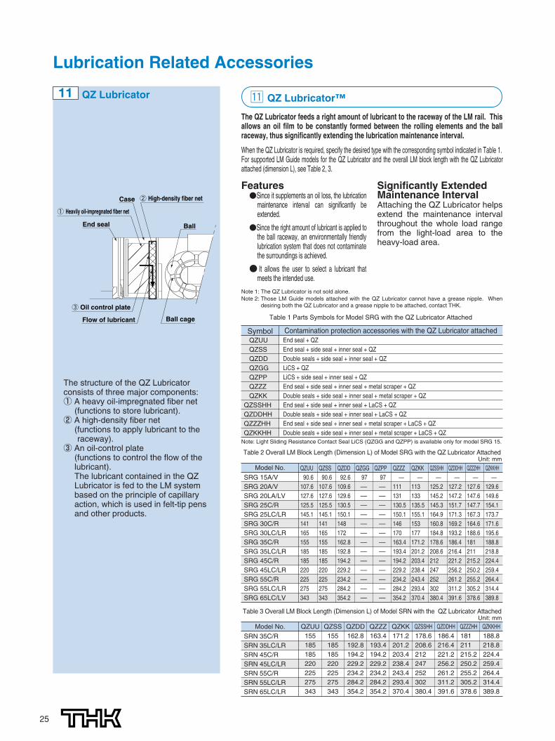
11 QZ Lubricator
End seal
Flow of lubricant
③ Oil control plate
Ball cage
Ball
Case ② High-density fiber net
① Heavily oil-impregnated fiber net
The QZ Lubricator feeds a right amount of lubricant to the raceway of the LM rail. Thisallows an oil film to be constantly formed between the rolling elements and the ballraceway, thus significantly extending the lubrication maintenance interval.
When the QZ Lubricator is required, specify the desired type with the corresponding symbol indicated in Table 1.For supported LM Guide models for the QZ Lubricator and the overall LM block length with the QZ Lubricatorattached (dimension L), see Table 2, 3.
⁄1 QZ Lubricator™
Features●Since it supplements an oil loss, the lubrication
maintenance interval can significantly beextended.
●Since the right amount of lubricant is applied tothe ball raceway, an environmentally friendlylubrication system that does not contaminatethe surroundings is achieved.
● It allows the user to select a lubricant thatmeets the intended use.
Significantly ExtendedMaintenance IntervalAttaching the QZ Lubricator helpsextend the maintenance intervalthroughout the whole load rangefrom the light-load area to theheavy-load area.
Note 1: The QZ Lubricator is not sold alone.Note 2: Those LM Guide models attached with the QZ Lubricator cannot have a grease nipple. When
desiring both the QZ Lubricator and a grease nipple to be attached, contact THK.
Table 1 Parts Symbols for Model SRG with the QZ Lubricator Attached
Contamination protection accessories with the QZ Lubricator attachedEnd seal + QZEnd seal + side seal + inner seal + QZDouble seals + side seal + inner seal + QZLiCS + QZLiCS + side seal + inner seal + QZEnd seal + side seal + inner seal + metal scraper + QZDouble seals + side seal + inner seal + metal scraper + QZEnd seal + side seal + inner seal + LaCS + QZDouble seals + side seal + inner seal + LaCS + QZEnd seal + side seal + inner seal + metal scraper + LaCS + QZDouble seals + side seal + inner seal + metal scraper + LaCS + QZ
Table 2 Overall LM Block Length (Dimension L) of Model SRG with the QZ Lubricator Attached
Model No.
SRG 15A/VSRG 20A/VSRG 20LA/LVSRG 25C/RSRG 25LC/LRSRG 30C/RSRG 30LC/LRSRG 35C/RSRG 35LC/LRSRG 45C/RSRG 45LC/LRSRG 55C/RSRG 55LC/LRSRG 65LC/LV
QZUU90.6
107.6127.6125.5145.1141165155185185220225275343
QZSS90.6
107.6127.6125.5145.1141165155185185220225275343
QZDD92.6
109.6129.6130.5150.1148172162.8192.8194.2229.2234.2284.2354.2
QZGG97—————————————
QZPP97—————————————
QZZZ—
111131130.5150.1146170163.4193.4194.2229.2234.2284.2354.2
QZKK—
113133135.5155.1153177171.2201.2203.4238.4243.4293.4370.4
QZSSHH—
125.2145.2145.3164.9160.8184.8178.6208.6212247252302380.4
QZDDHH—
127.2147.2151.7171.3169.2193.2186.4216.4221.2256.2261.2311.2391.6
QZZZHH—
127.6147.6147.7167.3164.6188.6181211215.2250.2255.2305.2378.6
QZKKHH—
129.6149.6154.1173.7171.6195.6188.8218.8224.4259.4264.4314.4389.8
Unit: mm
Note: Light Sliding Resistance Contact Seal LiCS (QZGG and QZPP) is available only for model SRG 15.
Table 3 Overall LM Block Length (Dimension L) of Model SRN with the QZ Lubricator Attached
Model No.
SRN 35C/RSRN 35LC/LRSRN 45C/RSRN 45LC/LRSRN 55C/RSRN 55LC/LRSRN 65LC/LR
QZUU155185185220225275343
QZSS155185185220225275343
QZDD162.8192.8194.2229.2234.2284.2354.2
QZZZ163.4193.4194.2229.2234.2284.2354.2
QZKK171.2201.2203.4238.4243.4293.4370.4
QZSSHH178.6208.6212.0247.0252.0302.0380.4
QZDDHH186.4216.4221.2256.2261.2311.2391.6
QZZZHH181.0211.0215.2250.2255.2305.2378.6
QZKKHH188.8218.8224.4259.4264.4314.4389.8
Unit: mm
SymbolQZUUQZSSQZDDQZGGQZPPQZZZQZKK
QZSSHHQZDDHHQZZZHHQZKKHH
The structure of the QZ Lubricatorconsists of three major components:① A heavy oil-impregnated fiber net
(functions to store lubricant).② A high-density fiber net
(functions to apply lubricant to theraceway).
③ An oil-control plate(functions to control the flow of thelubricant).The lubricant contained in the QZLubricator is fed to the LM systembased on the principle of capillaryaction, which is used in felt-tip pensand other products.
906-0769_P19-25.2C(DIC2591) 09.8.5 10:00 AM ページ 25

26
OPTIONSOptions
Models SRG/SRN allow lubrication from both the side and top faces of the LM block.The greasing hole of standard types is not drilled through in order to prevent foreignmaterial from entering the LM block. When using the greasing hole, contact THK.
The greasing interval is longer than full-roller type LM Guides thanksto the roller cage effect. However, the greasing interval variesaccording to the service environment such as a heavy load and highspeeds. Contact THK for details.
⁄2 Greasing Hole 12Greasing hole
Model No.Pilot hole for side nipple
e0 f0 D0
Applicablenipple D2 (O-ring) V e1
Greasing hole on the top face
SRG15ASRG15VSRG20A/LASRG20V/LVSRG 25CSRG 25LCSRG 25RSRG 25LRSRG 30CSRG 30LCSRG 30RSRG 30LRSRG 35CSRG 35LCSRG 35RSRG 35LRSRG 45CSRG 45LCSRG 45RSRG 45LRSRG 55CSRG 55LCSRG 55RSRG 55LRSRG 65LCSRG 65LV
4 6 2.9 PB107 9.2(P6) 0.5 5.5
4 6 2.9 PB107 9.2(P6) 0.5 6.54 6 2.9 PB107 9.2(P6) 0.5 6.5
6 6.4 5.2 M6F 10.2(P7) 0.5 6
6 10.4 5.2 M6F 10.2(P7) 4.5 6
6 6.2 5.2 M6F 10.2(P7) 0.4 6
6 9.2 5.2 M6F 10.2(P7) 3.4 6
6 6 5.2 M6F 10.2(P7) 0.4 6
6 13.0 5.2 M6F 10.2(P7) 7.4 6
7 7 5.2 M6F 10.2(P7) 0.4 7
7 17.0 5.2 M6F 10.2(P7) 10.4 7
9 8.5 5.2 M6F 10.2(P7) 0.4 11
9 18.5 5.2 M6F 10.2(P7) 10.4 11
9 13.5 5.2 M6F 10.2(P7) 0.4 109 13.5 5.2 M6F 10.2(P7) 0.4 10
Model No.Pilot hole for side nipple
e0 f0 D0
Applicablenipple D2 (O-ring) V e1
Greasing hole on the top face
SRN 35CSRN 35LCSRN 35RSRN 35LRSRN 45CSRN 45LCSRN 45RSRN 45LRSRN 55CSRN 55LCSRN 55RSRN 55LRSRN 65LCSRN 65LR
8.0 6.5 5.2 M6F 10.2(P7) 0.4 6
8.0 6.5 5.2 M6F 10.2(P7) 0.4 6
8.5 7.0 5.2 M6F 10.2(P7) 0.4 7
8.5 7.0 5.2 M6F 10.2(P7) 0.4 7
10.0 8.0 5.2 M6F 10.2(P7) 0.4 11
10.0 8.0 5.2 M6F 10.2(P7) 0.4 11
9.0 11.0 5.2 M6F 10.2(P7) 0.4 109.0 11.0 5.2 M6F 10.2(P7) 0.4 10
Note: When using the greasing hole on the top face of models SRG-R and SRG-LR, a greasing adapteris separately required. Contact THK for details.
e1
Greasing holeon the top faceφD2 depth1
Vf0
e0
φD0Side nipple(M6 pilot hole)
Method for using the greasing hole on the top face
O-ring
Unit: mm
Unit: mm
906-0769_P26.4C(C95M40) 09.8.5 10:03 AM ページ 26

Caged Roller LM Guide SRG/SRNPrecautions on use
� Handling� Disassembling components may cause dust to enter the system or degrade mounting accuracy of parts. Do not disassemble the
product.� Tilting an LM block or LM rail may cause them to fall by their own weight.� Dropping or hitting the LM Guide may damage it. Giving an impact to the LM Guide could also cause damage to its function even if
the guide looks intact.� Lubrication
� Thoroughly remove anti-corrosion oil and feed lubricant before using the product.� Do not mix lubricants of different physical properties.� In locations exposed to constant vibrations or in special environments such as clean rooms, vacuum and low/high temperature,
normal lubricants may not be used. Contact THK for details.� When planning to use a special lubricant, contact THK before using it.� When adopting oil lubrication, the lubricant may not be distributed throughout the LM system depending on the mounting orientation
of the system. Contact THK for details.� Lubrication interval varies according to the service conditions. Contact THK for details.
� Precautions on Use� Entrance of foreign matter may cause damage to the ball circulating path or functional loss. Prevent foreign matter, such as dust or
cutting chips, from entering the system.� When planning to use the LM system in an environment where coolant penetrates the LM block, it may cause trouble to product
functions depending on the type of coolant. Contact THK for details.� Do not use the LM system at temperature of 80℃ or higher. When desiring to use the system at temperature of 80℃ or higher,
contact THK in advance.� If foreign matter adheres to the LM system, replenish the lubricant after cleaning the product. For available types of detergent,
contact THK .� When using the LM Guide with an inverted mount, breakage of the endplate due to an accident or the like may cause balls to fall
out and the LM block to come off from the LM rail and fall. In these cases, take preventive measures such as adding a safetymechanism for preventing such falls.
� When using the LM system in locations exposed to constant vibrations or in special environments such as clean rooms, vacuumand low/high temperature, contact THK in advance.
� When removing the LM block from the LM rail and then replacing the block, an LM block mounting/removing jig that facilitates suchinstallation is available. Contact THK for details.
� Storage� When storing the LM Guide, enclose it in a package designated by THK and store it in a horizontal orientation while avoiding high
temperature, low temperature and high humidity.
● “LM GUIDE,” and “ ” are registered trademarks of THK CO., LTD.● The photo may differ slightly in appearance from the actual product.● The appearance and specifications of the product are subject to change without notice. Contact THK before placing an order.● Although great care has been taken in the production of this catalog, THK will not take any responsibility for damage resulting from typographical errors or omissions.● For the export of our products or technologies and for the sale for exports, THK in principle complies with the foreign exchange law and the Foreign Exchange
and Foreign Trade Control Law as well as other relevant laws.For export of THK products as single items, contact THK in advance. All rights reserved
HEAD OFFICE 3-11-6, NISHI-GOTANDA, SHINAGAWA-KU, TOKYO 141-8503 JAPAN INTERNATIONAL SALES DEPARTMENT PHONE:+81-3-5434-0351 FAX:+81-3-5434-0353
TAIWANTHK TAIWAN CO.,LTD.
TAIPEI HEAD OFFICEPhone:+886-2-2888-3818TAICHUNG OFFICEPhone:+886-4-2359-1505 TAINAN OFFICEPhone:+886-6-289-7668
KOREASEOUL REPRESENTATIVE OFFICE
Phone:+82-2-3468-4351SINGAPORETHK LM SYSTEM Pte. Ltd.
NORTH AMERICATHK America,Inc.
HEADQUARTERSPhone:+1-847-310-1111 Fax:+1-847-310-1271CHICAGO OFFICEPhone:+1-847-310-1111 Fax:+1-847-310-1182NORTH EAST OFFICE Phone:+1-845-369-4035 Fax:+1-845-369-4909ATLANTA OFFICEPhone:+1-770-840-7990 Fax:+1-770-840-7897LOS ANGELES OFFICEPhone:+1-949-955-3145 Fax:+1-949-955-3149SAN FRANCISCO OFFICEPhone:+1-925-455-8948 Fax:+1-925-455-8965DETROIT OFFICEPhone:+1-248-858-9330 Fax:+1-248-858-9455TORONTO OFFICEPhone:+1-905-820-7800 Fax:+1-905-820-7811
SOUTH AMERICATHK Brasil LTDA
Phone:+55-11-3767-0100 Fax:+55-11-3767-0101EUROPETHK GmbH
DÜSSELDORF OFFICEPhone:+49-2102-7425-0 Fax:+49-2102-7425-299
EUROPEAN HEADQUARTERSPhone:+49-2102-7425-555 Fax:+49-2102-7425-556
SHANGHAI OFFICEPhone:+86-21-6219-3000 Fax:+86-21-6219-9890BEIJING OFFICEPhone:+86-10-8441-7277 Fax:+86-10-6590-3557CHENGDU OFFICEPhone:+86-28-8526-8025 Fax:+86-28-8525-6357GUANGZHOU OFFICEPhone:+86-20-8523-8418 Fax:+86-20-3801-0456
CHINATHK (CHINA) CO.,LTD.
TURKEY OFFICEPhone:+90-216-362-4050 Fax:+90-216-569-7150
MOSCOW OFFICEPhone:+7-495-649-80-47 Fax:+7-495-649-80-44
FRANKFURT OFFICEPhone:+49-2102-7425-650 Fax:+49-2102-7425-699STUTTGART OFFICEPhone:+49-7150-9199-0 Fax:+49-7150-9199-888MÜNCHEN OFFICEPhone:+49-8937-0616-0 Fax:+49-8937-0616-26U.K. OFFICEPhone:+44-1908-30-3050 Fax:+44-1908-30-3070ITALY MILANO OFFICEPhone:+39-039-284-2079 Fax:+39-039-284-2527ITALY BOLOGNA OFFICEPhone:+39-051-641-2211 Fax:+39-051-641-2230SWEDEN OFFICEPhone:+46-8-445-7630 Fax:+46-8-445-7639 AUSTRIA OFFICEPhone:+43-7229-51400 Fax:+43-7229-51400-79SPAIN OFFICEPhone:+34-93-652-5740 Fax:+34-93-652-5746
EINDHOVEN OFFICETHK Europe B.V.
THK France S.A.S.Phone:+33-4-3749-1400
Phone:+31-040-290-9500 Fax:+31-040-290-9599
Fax:+33-4-3749-1401
HEADQUARTERSPhone:+86-411-8733-7111 Fax:+86-411-8733-7000
THK (SHANGHAI) CO.,LTD.Phone:+86-21-6275-5280 Fax:+86-21-6219-9890
Fax:+886-2-2888-3819
Fax:+886-4-2359-1506
Fax:+886-6-289-7669
Fax:+82-2-3468-4353
Fax:+65-6884-5550INDIABANGALORE REPRESENTATIVE OFFICE
Phone:+91-80-2330-1524
Phone:+65-6884-5500
Fax:+91-80-2314-8226
Global site : http://www.thk.com/
©THK CO., LTD. 200908030 E10 Printed in Japan
PRAGUE OFFICEPhone:+420-2-41025-100 Fax:+420-2-41025-199
906-0769_H1-4_P01.4C(C95M40) 09.8.5 9:57 AM ページ h4