Embed Size (px)
Citation preview

Complexity of Accelerator Driven System
P. Singh
Bhabha Atomic Research Centre
Mumbai-400 085
Email: [email protected]
Plan of the talk:
1. Introduction
2. Why is Accelerator Driven sub-critical reactor System (ADS) so important?
3. Issues with ADS
4. Summary & conclusions.
Indo-Japan Accelerator School, IUAC Feb 17, 2015
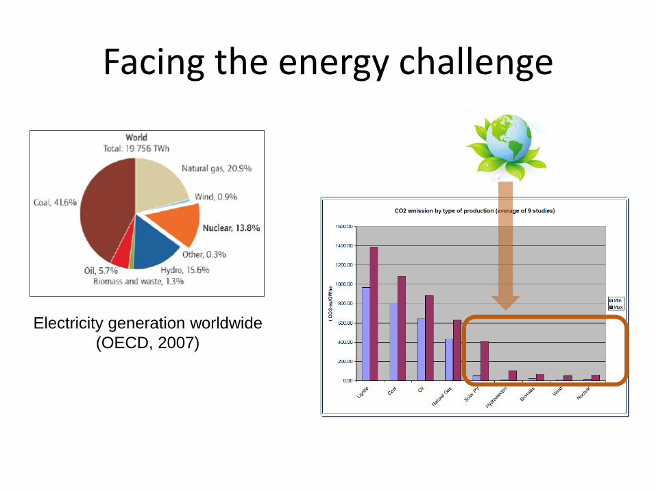
Facing the energy challenge
Electricity generation worldwide
(OECD, 2007)

IAEA report-2006
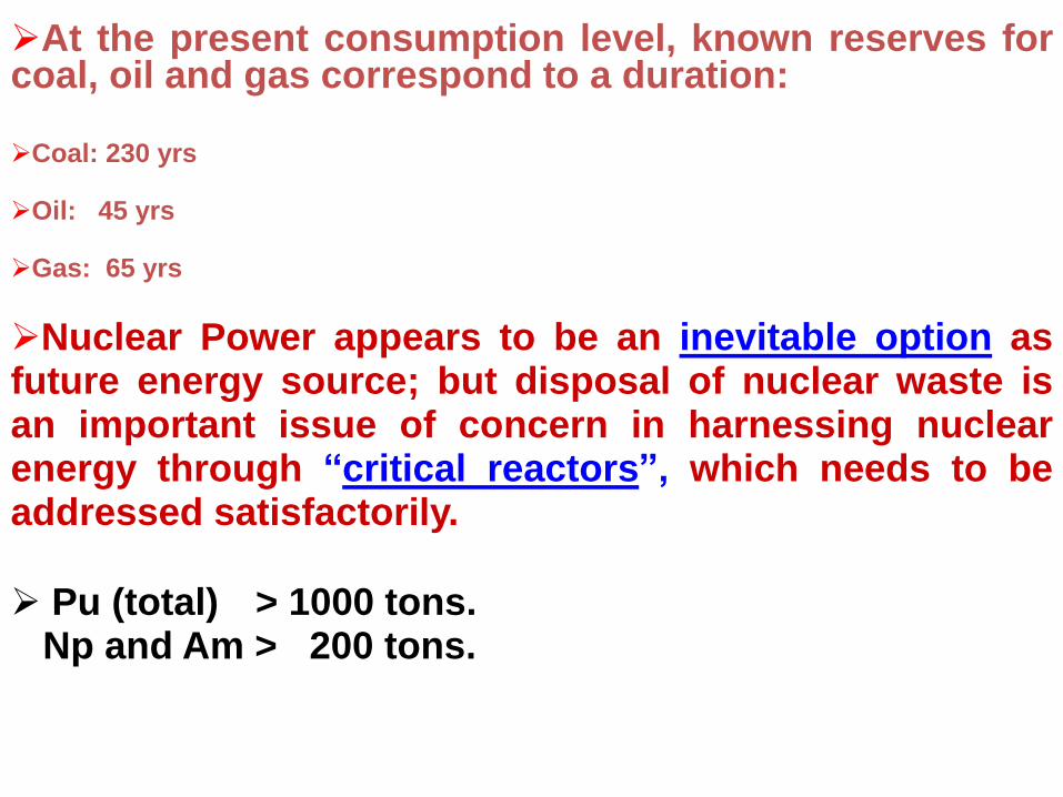
At the present consumption level, known reserves for coal, oil and gas correspond to a duration:
Coal: 230 yrs
Oil: 45 yrs
Gas: 65 yrs
Nuclear Power appears to be an inevitable option as future energy source; but disposal of nuclear waste is an important issue of concern in harnessing nuclear energy through “critical reactors”, which needs to be addressed satisfactorily.
Pu (total) > 1000 tons. Np and Am > 200 tons.

Current Challenges in Nuclear Waste Management
• Long Lived Minor actinides (MA) & Fission products
• Minor actinides with high activity
• 239Pu (T1/2 24110 yrs)
• 237Np (T1/2 2.1 million yrs)
• 241Am (T1/2 432 yrs)
• decay from fission products
• 90Sr (T1/2 28.9yrs)
• 137Cs (T1/2 30 yrs)
• 129 I (T1/2 15.7 million yrs)
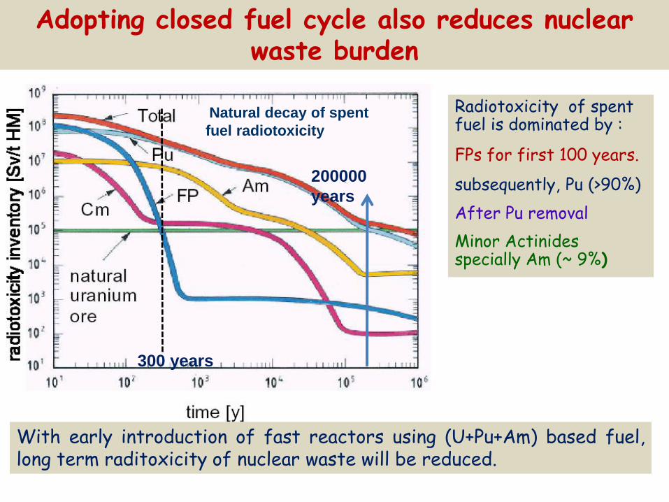
Adopting closed fuel cycle also reduces nuclear waste burden
Radiotoxicity of spent fuel is dominated by :
FPs for first 100 years.
subsequently, Pu (>90%)
After Pu removal
Minor Actinides specially Am (~ 9%)
Natural decay of spent
fuel radiotoxicity
With early introduction of fast reactors using (U+Pu+Am) based fuel, long term raditoxicity of nuclear waste will be reduced.
200000
years
300 years
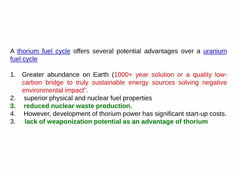
A thorium fuel cycle offers several potential advantages over a uranium
fuel cycle
1. Greater abundance on Earth (1000+ year solution or a quality low-
carbon bridge to truly sustainable energy sources solving negative
environmental impact”.
2. superior physical and nuclear fuel properties
3. reduced nuclear waste production.
4. However, development of thorium power has significant start-up costs.
3. lack of weaponization potential as an advantage of thorium

Attractive Features of Thorium / Thoria
• High Abundance – Uniformly distributed in earth crust – 3 to 4 times abundant than uranium
• Better Fuel Performance Characteristics – Higher melting point – Better thermal conductivity – Lower fission gas release – Good radiation resistance and
dimensional stability – Reduced fuel deterioration in the event
of failure • Relative ease in Waste Management
– No oxidation -Superior behavior and suitable for direct disposal in repository as it is mono-valent.
– Generates less plutonium and minor actinides
MA MA from LMFBR (U-Pu Cycle), kg/GWeY
MA from Th-U cycle, Kg/GWeY
Np237 4.6 0.06
Am241 4.0 1E-7
Am242 0.07 0
Am243 1.9 0
Cm242 0.11 0
Cm244 0.13 0
Comparison of MAs produced in (Th-U) and (U –Pu) cycle
Minor actinide (g/T)
U235 + U238
U235 +Th232
U233+ U238
U233 +Th232
Np 900 107 13 3
Am 470 0.28 117 0.0018
Cm 220 0.14 132 0.00064
Production of minor actinides in U and Th fuel cycle in g/t of heavy metals at 60 GWD/t
MA production in U233-Th232 cycle is few orders lower!

Neutronic characteristics of fissile and fertile nuclides
• Larger thermal capture cross-section of thorium leading to lower losses due to structural and other parasitic captures – Improved conversion of Th232 to U233
• Constant η value (> 2.0) over a wide energy range – Higher conversion ratios with thorium utilisation in reactors operating in
the thermal/epithermal spectrum.
0
1
2
3
4
5
6
7
8
U238
Th232
Therm
al C
aptu
re
cro
ss s
ection (
barn
)
1eV 100eV 10keV 1MeV0
1
2
3
4
U235
U233
Pu239
Num
ber
of neutr
ons
rele
ase
d
per
neutr
on a
bso
rbed, [
]
Neutron energy
Thorium acts as a burnable poison in initial stages while contributes towards additional reactivity through U233 formation at a later stage- “fissible” poison
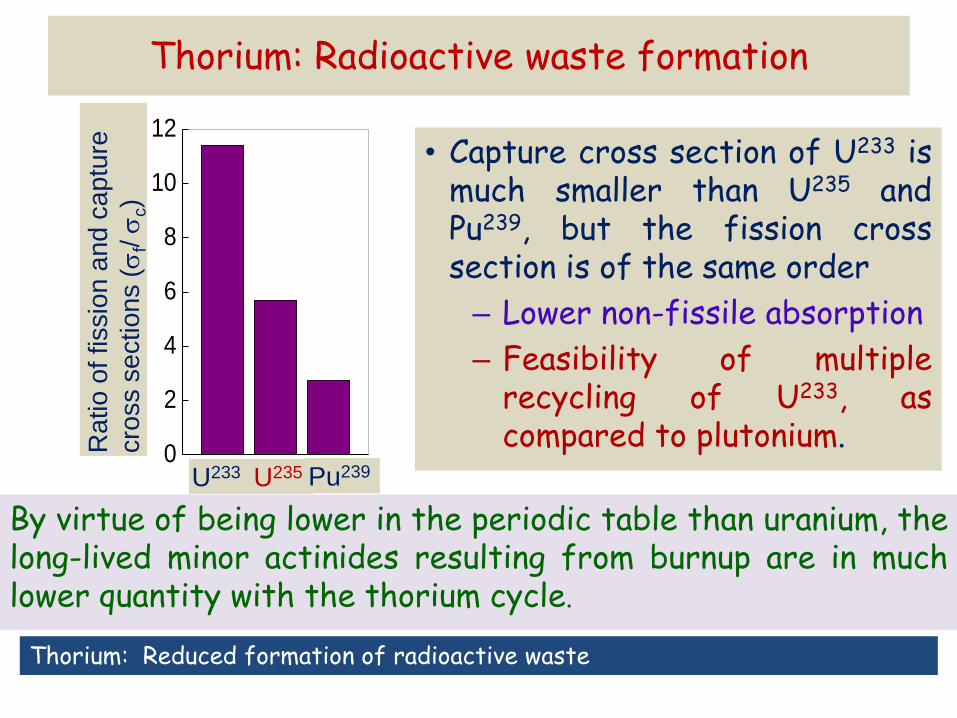
Thorium: Radioactive waste formation
• Capture cross section of U233 is much smaller than U235 and Pu239, but the fission cross section is of the same order
– Lower non-fissile absorption
– Feasibility of multiple recycling of U233, as compared to plutonium.
By virtue of being lower in the periodic table than uranium, the long-lived minor actinides resulting from burnup are in much lower quantity with the thorium cycle.
0
2
4
6
8
10
12R
atio
of fissio
n a
nd
ca
ptu
re
cro
ss s
ectio
ns (
f/
c)
U233 U235 Pu239
Thorium: Reduced formation of radioactive waste
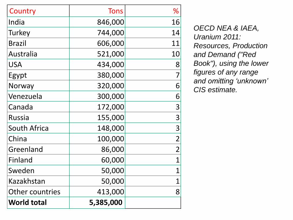
Country Tons %
India 846,000 16
Turkey 744,000 14
Brazil 606,000 11
Australia 521,000 10
USA 434,000 8
Egypt 380,000 7
Norway 320,000 6
Venezuela 300,000 6
Canada 172,000 3
Russia 155,000 3
South Africa 148,000 3
China 100,000 2
Greenland 86,000 2
Finland 60,000 1
Sweden 50,000 1
Kazakhstan 50,000 1
Other countries 413,000 8
World total 5,385,000
OECD NEA & IAEA,
Uranium 2011:
Resources, Production
and Demand ("Red
Book"), using the lower
figures of any range
and omitting ‘unknown’
CIS estimate.
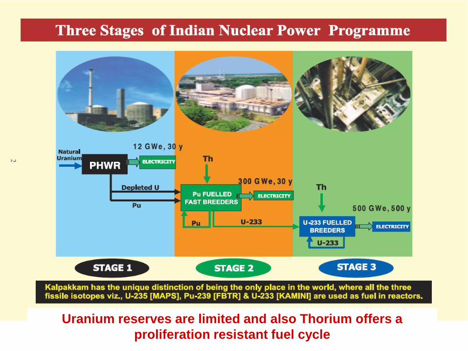
Uranium reserves are limited and also Thorium offers a
proliferation resistant fuel cycle

Produce Energy
Efficient use of Thorium resources
Transmutation of high level long-lived
radioactive waste
Incineration of Minor Actinides
India needs a system which
can…
ADS

Accelerator Driven Sub-critical Reactor System (ADS)
A new type of fission reactor, where
nuclear power (say, 500-1000 MWe)
can be generated in a neutron multiplying core (keff < 1.000 )
without the need of criticality.
But, ADS has to be driven by an
external neutron source and
hence it is inherently safe system
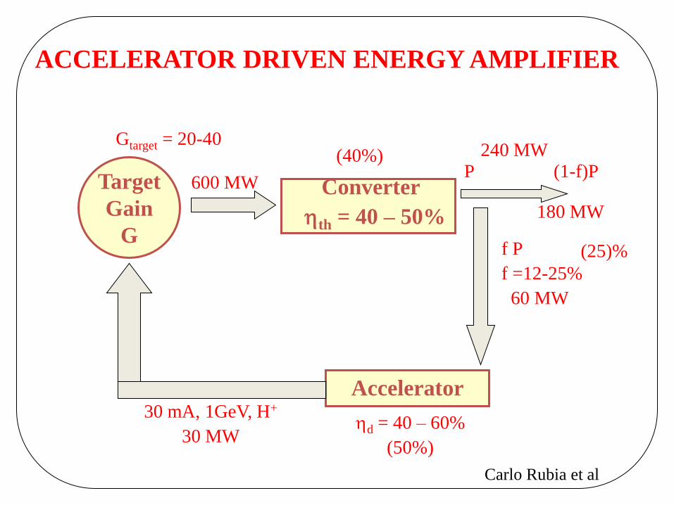
ACCELERATOR DRIVEN ENERGY AMPLIFIER
Target
Gain
G
Converter
th = 40 – 50%
Accelerator
d = 40 – 60%
(50%)
P (1-f)P
180 MW
30 mA, 1GeV, H+
30 MW
Gtarget = 20-40
f P
f =12-25%
60 MW
600 MW
240 MW (40%)
(25)%
Carlo Rubia et al

SCHEMATIC OF ACCELERATOR-DRIVEN SYSTEM
LINAC


ADS Energy generation using Thorium
Transmutation
Incineration
By Spallation process with GeV
energy protons striking on high Z
target.
Number of neutrons per proton
per Watt of beam power reaches a
plateau just above 1 GeV.
Most cost effective way to produce
neutrons
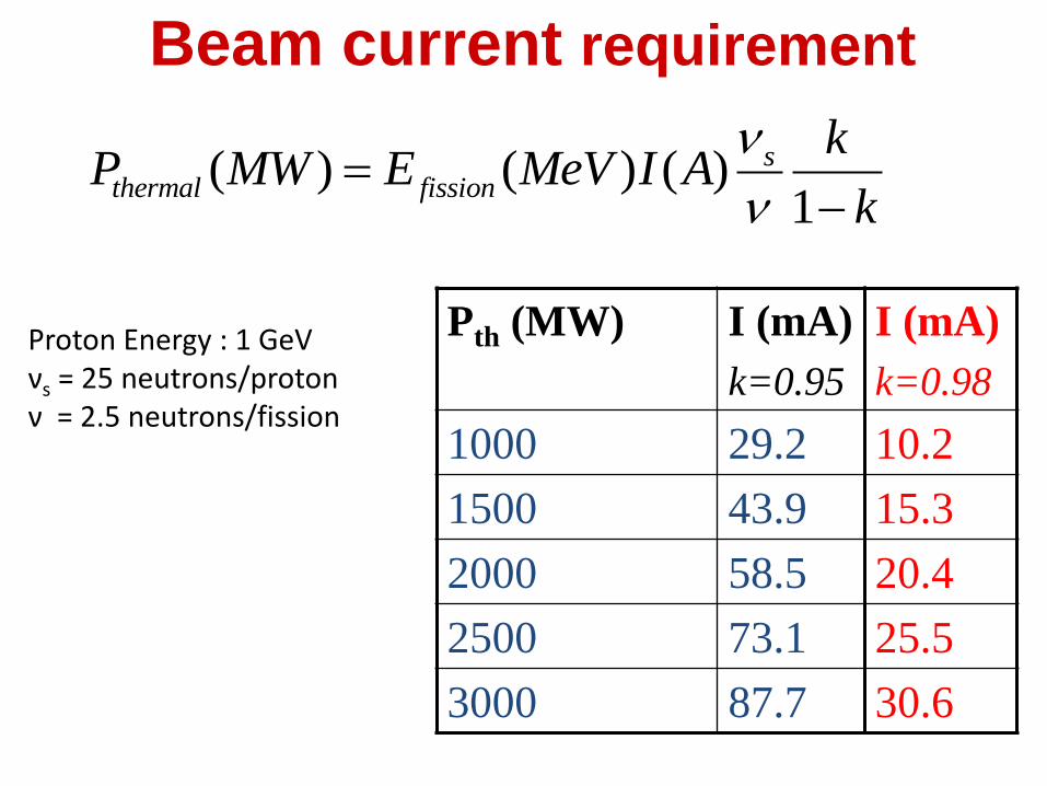
( ) ( ) ( )1
sthermal fission
kP MW E MeV I A
k
Pth (MW) I (mA)
k=0.95
1000 29.2
1500 43.9
2000 58.5
2500 73.1
3000 87.7
Proton Energy : 1 GeV νs = 25 neutrons/proton ν = 2.5 neutrons/fission
I (mA)
k=0.98
10.2
15.3
20.4
25.5
30.6
Beam current requirement

Power required
keff=0.95, i=33.7mA
keff=0.99
i=6.5mA
To meet a constraint of a 10 MW proton accelerator we need keff>0.985
21
Role of ADS in Indian nuclear power systems
• For sustainable thorium-based fuel cycle by introducing non-fission neutrons in the neutron inventory.
• For cleaner nuclear power from thorium that generates reduced minor actinides waste in the spent fuel.
• A safer way to incinerate minor actinides from spent U-Pu fuel system of stages-1 & 2 of the 3-stage nuclear power programme.

JAPAN
KOREA
ITALY
CHINA
BELGIUM
FRANCE
GERMANY
RUSSIA
USA
Under its OMEGA (Option Making Extra Gains of Actinides and FP), that is
extension of its earlier Actinides Burner Reactor (ABR).
Under its HYPER (Hybrid Power Extraction Reactor) programme.
Under its TRASCO (TRAnsmutazion SCOrie) Programme and, Industrial project
undertaken by ANSALDO for EC.
Proposed as CIAE+IHEP project but under an un-named ADS programme of
Sino-Italian collaboration.
Under MYRRHA project as extension of ADONIS (Accelerator-Driven Operated
New Irradiation System) programme for radioisotope production.
Its CNRS/IN2P3 institutes are spearheading waste incineration R&D with spinoff
of its TRISPAL activities for accelerator to ADS.
Activities under FZK in the yet un-named programme.
Undertaken several study projects in ITEP/ISTC against the EC/US funding.
Earlier as ATW. Now AAA (Advanced Accelerator Applications) aiming for having
ADTF in 10 years from 2001. Full technological Demo in next 10 years.
Some of the ADS Projects around the world

Reactor
• Subcritical or Critical modes
• 65 to 100 MWth
Accelerator
(600 MeV - 4 mA proton)
Fast
Neutron
Source
Spallation Source
Lead-Bismuth
coolant
Multipurpose
Flexible
Irradiation
Facility
MYRRHA - Accelerator Driven System
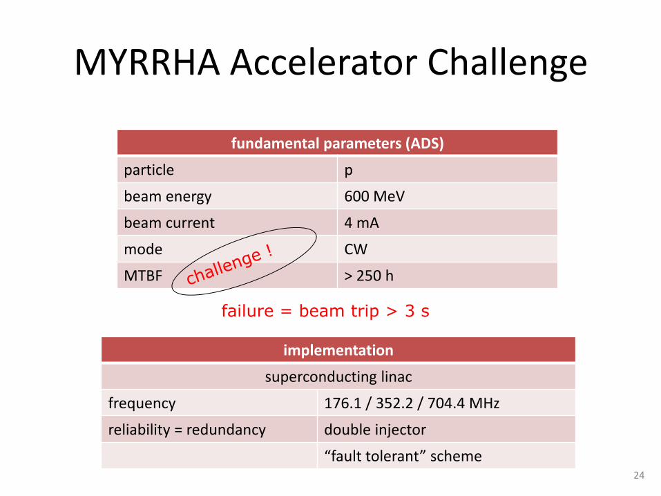
MYRRHA Accelerator Challenge
fundamental parameters (ADS)
particle p
beam energy 600 MeV
beam current 4 mA
mode CW
MTBF > 250 h
implementation
superconducting linac
frequency 176.1 / 352.2 / 704.4 MHz
reliability = redundancy double injector
“fault tolerant” scheme 24
failure = beam trip > 3 s

MEGAPIE (SINQ Facility, PSI) CYCLOTRON-DRIVEN
Ran successfully for 4 months in 2006
700 kW, CW, liquid Pb-Bi
First Pb-Bi spallation target
‘Makes future licensing simpler’
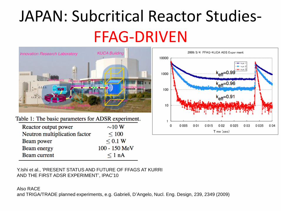
JAPAN: Subcritical Reactor Studies- FFAG-DRIVEN
Y.Ishi et al., ‘PRESENT STATUS AND FUTURE OF FFAGS AT KURRI
AND THE FIRST ADSR EXPERIMENT’, IPAC’10
Also RACE
and TRIGA/TRADE planned experiments, e.g. Gabrieli, D’Angelo, Nucl. Eng. Design, 239, 2349 (2009)
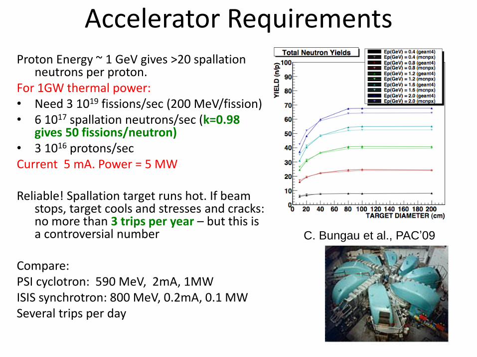
Accelerator Requirements Proton Energy ~ 1 GeV gives >20 spallation
neutrons per proton. For 1GW thermal power: • Need 3 1019 fissions/sec (200 MeV/fission) • 6 1017 spallation neutrons/sec (k=0.98
gives 50 fissions/neutron) • 3 1016 protons/sec Current 5 mA. Power = 5 MW Reliable! Spallation target runs hot. If beam
stops, target cools and stresses and cracks: no more than 3 trips per year – but this is a controversial number
Compare: PSI cyclotron: 590 MeV, 2mA, 1MW ISIS synchrotron: 800 MeV, 0.2mA, 0.1 MW Several trips per day
C. Bungau et al., PAC’09
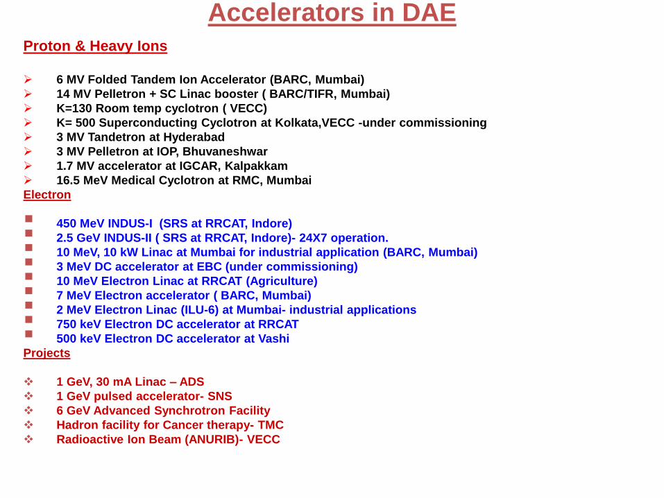
Proton & Heavy Ions
6 MV Folded Tandem Ion Accelerator (BARC, Mumbai)
14 MV Pelletron + SC Linac booster ( BARC/TIFR, Mumbai)
K=130 Room temp cyclotron ( VECC)
K= 500 Superconducting Cyclotron at Kolkata,VECC -under commissioning
3 MV Tandetron at Hyderabad
3 MV Pelletron at IOP, Bhuvaneshwar
1.7 MV accelerator at IGCAR, Kalpakkam
16.5 MeV Medical Cyclotron at RMC, Mumbai
Electron
450 MeV INDUS-I (SRS at RRCAT, Indore)
2.5 GeV INDUS-II ( SRS at RRCAT, Indore)- 24X7 operation.
10 MeV, 10 kW Linac at Mumbai for industrial application (BARC, Mumbai)
3 MeV DC accelerator at EBC (under commissioning)
10 MeV Electron Linac at RRCAT (Agriculture)
7 MeV Electron accelerator ( BARC, Mumbai)
2 MeV Electron Linac (ILU-6) at Mumbai- industrial applications
750 keV Electron DC accelerator at RRCAT
500 keV Electron DC accelerator at Vashi
Projects
1 GeV, 30 mA Linac – ADS
1 GeV pulsed accelerator- SNS
6 GeV Advanced Synchrotron Facility
Hadron facility for Cancer therapy- TMC
Radioactive Ion Beam (ANURIB)- VECC
Accelerators in DAE
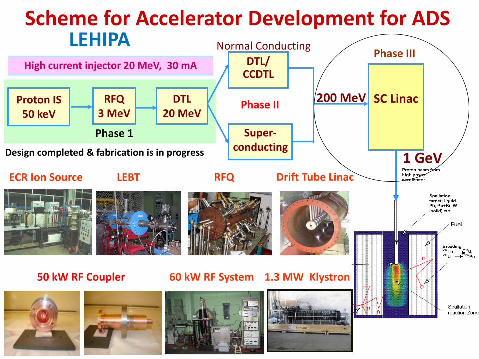
Proton IS 50 keV
RFQ 3 MeV
DTL 20 MeV
DTL/ CCDTL
Super- conducting
SC Linac
1 GeV
200 MeV
Normal Conducting
High current injector 20 MeV, 30 mA
Scheme for Accelerator Development for ADS
Design completed & fabrication is in progress
ECR Ion Source LEBT RFQ Drift Tube Linac
60 kW RF System 1.3 MW Klystron
Phase 1
Phase II
Phase III LEHIPA
50 kW RF Coupler

RRCAT pulsed
BARC CW
1 GeV
Project X
CW upto 3 GeV

LEBT
MEBT Elliptical
Cavities
200 MeV 1 GeV
IS RFQ HWR,
SSR
50 keV 3 MeV 150 MeV
Elliptical Cavities
Scheme for the 1 GeV High Intensity
Superconducting Proton Accelerator (HISPA) Frequency: 325 and 650 MHz

High Yield Neutron Facility
IS DTL
LEBT MEBT
RFQ
Proton Current = 30 mA
1.00E+14
6.00E+14
1.10E+15
1.60E+15
2.10E+15
2.60E+15
3.10E+15
3.60E+15
4.10E+15
0 5 10 15 20 25
Proton Energy (MeV)
Yie
ld (
Ne
utr
on
s/s
ec)
Reflector(Pb)
Moderator
Beryllium target
Proton Beam
(20 MeV, 30 mA)
S0(EP) = 4.476 x 10¹¹ x EP1.886 x I n/sec
Neutron Yield for Beryllium target

33
20 MeV Proton beam for ADS
experiments in HWR critical facility
Linac tunnel in
basement
Beam transport
line thru’
basement
Ground level
beam transport
gallery- with
shielding
HWR critical
facility building
Studies have
confirmed feasibility
of extending 20 MeV
proton beam to a
target in the core of
nearby HWR critical
facility.
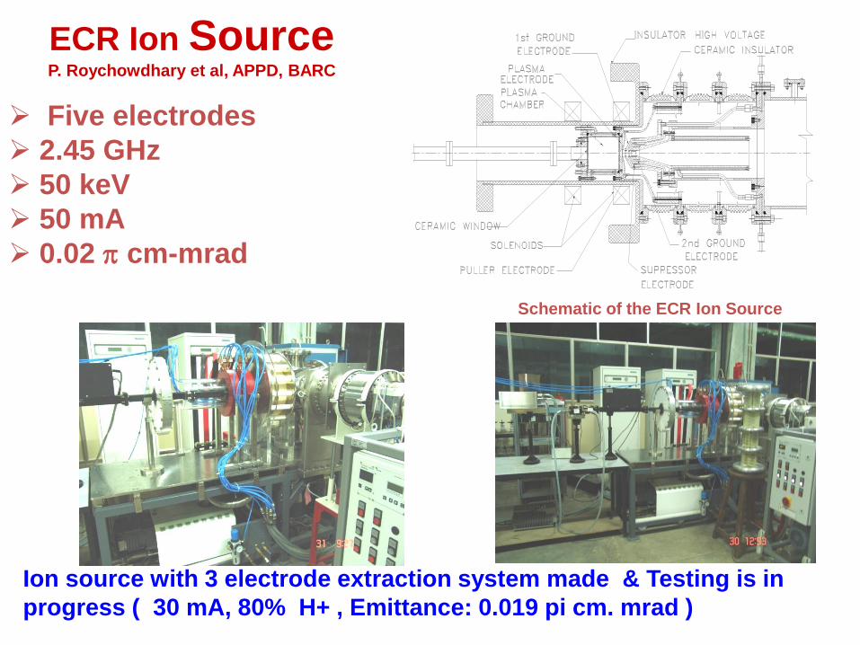
Five electrodes
2.45 GHz
50 keV
50 mA
0.02 cm-mrad
ECR Ion Source P. Roychowdhary et al, APPD, BARC
Schematic of the ECR Ion Source
Ion source with 3 electrode extraction system made & Testing is in
progress ( 30 mA, 80% H+ , Emittance: 0.019 pi cm. mrad )

3 MeV RFQ under fabrication at BATL
- 4 segments ( 1 m each)
Tuners 64 tuners --- 16 per quadrant,
symmetrically placed in each
quadrant.
Static tuners.
Cooling required.
Tuning Range : 468.5 kHz/mm (all)
24 vacuum ports
Frequency detuning :
745.86 kHz (all)
Vacuum ports
Coupling cell

Solenoid 2 Solenoid 1
Faraday cup
BPM 2 BPM 1
Design, development and characterization of LEBT systems
He++, D+ and H+ beams were extracted.
LEHIPA LEBT and its
components have been
designed and fabricated.
It is ready for assembly.
y = 0.1816x2 - 0.9843x + 10.462
R2 = 0.8934
9
9.2
9.4
9.6
9.8
10
10.2
10.4
10.6
10.8
11
0 1 2 3 4 5 6
Q
sig
ma^2
•Slit scan method
2'2'2 xxxxx
LEBT Test bench
•Solenoid scan method Emittance Measurement was done
LEHIPA LEBT
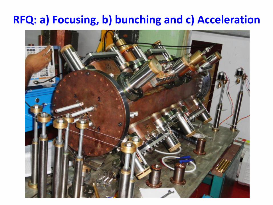
RFQ: a) Focusing, b) bunching and c) Acceleration

RFQ Testing

Pulse width= 5 msec
Pulse Period= 1 sec
1 sec
5 msec

Facility for carrying out experiments on physics of ADS and for
testing the simulations is being set up. This will use 14 MeV neutrons
produced through D+T reaction.
Simple sub-critical assembly (keff=0.87) of natural uranium is chosen
Measurements of flux distribution, flux spectra, total fission power,
source multiplication, and degree of sub-criticality will be carried out.
For this purpose a 400 keV RFQ is being built .
Presently a 400 keV DC accelerator is used
Experimental facility
For deuteron current of 1mA at 400 keV,
14 MeV neutron yield is 1.0x 10¹¹ n/s
D+T reaction

High Voltage
Power Supply
Ion
source
Dome Accelerating
Tube
Beam Steerer
BPM Faraday
Cup
Turbo
Molecular
Pump
14 MeV Neutron Generator (D+T)

Sub-critical facility for ADS Experiments, D+D and D+T , keff= 0.87
Reflector: BeO, Moderator: High Density Polyethylene.
Neutron Multiplication measured ( A. Sinha et al.)
BRAHMMA - “BeO Reflected And HDPE Moderated Multiplying Assembly

0
0.5
1
1.5
2
2.5
3
3.5
0 200 400 600 800 1000
30 mA
20 mA
10 mA
Hal
o p
aram
eter
Beam Energy (MeV)
Evolution of Beam Halo with 10%
mismatch in x, y and z for different
beam currents
Challenges in ADS accelerator design
Accelerators for ADS applications
•Require proton beam energy in the ~GeV range and operating with 10’s of mA beam
current
•Beam loss has to be limited to < 1 watt/m
•Require careful beam dynamics optimization to minimize the formation of beam halos
for a high current beam that could lead to beam loss and activation of the structure.
•Are required to operate in the CW mode making the thermal management of normal
conducting cavities difficult.
•Are required to be very reliable since they will be used for power production.
At present there is no such
accelerator operating in the
world!!

Beam loss produces activation that makes
maintenance difficult and time-consuming.
Control of beam halo formation and beam loss is a
fundamental requirement for high beam availability in
high-power proton linacs.
Beam mismatch is a major source of halo.
Mismatched beams evolve to a final equilibrium state with accompanying
growth of halo and emittance.
Beams are mismatched when focusing and defocusing forces (space charge
and emittance) are unbalanced, resulting in coherent rms oscillations.
Mismatched beam develops larger amplitudes than matched beam.

Maximum halo extent
0
1
2
3
4
5
6
-7.00 -5.00 -3.00 -1.00 1.00 3.00 5.00 7.00
matched
Quadrupole mode
Fast mode
Slow mode
X RMS size
log
(no
. of
par
ticl
es)
0
0.5
1
1.5
2
2.5
3
3.5
4
4.5
5
-6.00 -4.00 -2.00 0.00 2.00 4.00 6.00
matched
Quadrupole mode
Fast mode
Slow mode
log
(no
. of
par
ticl
es)
X RMS size
0
0.5
1
1.5
2
2.5
3
3.5
4
4.5
5
-6.00 -4.00 -2.00 0.00 2.00 4.00
matched
Quadrupole mode
Fast mode
Slow mode
X RMS size
log
(no
. of
par
ticl
es)

Output beam distribution for 30 % -30 % 30 % mismatch 10 mA 20 mA
30 mA 40 mA

Output beam distribution for a general mismatch
0
1
2
3
4
5
6
-8.00 -6.00 -4.00 -2.00 0.00 2.00 4.00
matched
10 % mismatch
20 % mismatch
30 % mismatch
40 % mismatch
log
(no
. of
par
ticl
es)
X RMS size
z
0
0.5
1
1.5
2
2.5
3
3.5
4
4.5
5
1.00 1.50 2.00 2.50 3.00 3.50
matched
10 % mismatch
20 % mismatch
30 % mismatch
40 % mismatch
X RMS size
log
(no
. of
par
ticl
es)
0
0.5
1
1.5
2
2.5
3
3.5
4
4.5
5
1.00 1.50 2.00 2.50 3.00 3.50
matched
10 % mismatch
20 % mismatch
30 % mismatch
40 % mismatch
X RMS size
log
(no
. of
par
ticl
es)
y x
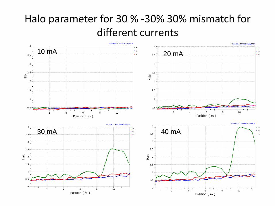
Halo parameter for 30 % -30% 30% mismatch for different currents
10 mA 20 mA
30 mA 40 mA
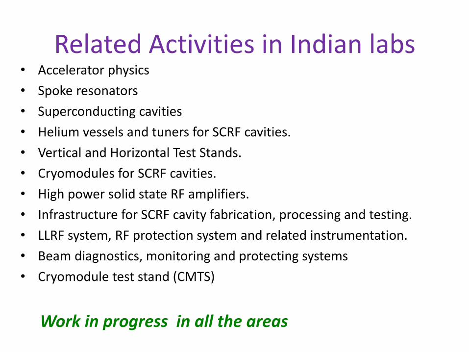
Related Activities in Indian labs • Accelerator physics
• Spoke resonators
• Superconducting cavities
• Helium vessels and tuners for SCRF cavities.
• Vertical and Horizontal Test Stands.
• Cryomodules for SCRF cavities.
• High power solid state RF amplifiers.
• Infrastructure for SCRF cavity fabrication, processing and testing.
• LLRF system, RF protection system and related instrumentation.
• Beam diagnostics, monitoring and protecting systems
• Cryomodule test stand (CMTS)
Work in progress in all the areas

Spallation target R&D at BARC ( P. Satyamurthy et al. )
• Computational codes development and nuclear data for spallation reaction analysis in the target.
• Thermal hydraulics computational tools development for LBE target simulations.
• Experimental loops for validation of thermal hydraulics codes and corrosion studies on window materials.

Possible Liquid
Targets
Elemen
t
Atomi
c
Mass
(A)
Atomic
Numbe
r (Z)
A/Z
Melting
Temper
ature
(0C)
Boiling
Temper
ature
(0C)
Densi
ty at
room
Temp
(g/cc)
Pb
207
82
2.52
4
327
1725
11.36
Bi
209
83
2.51
8
271
1560
9.80
LBE
~208
~82.5
~2.5
2
125
Similar
to
Pb/Bi
~10.0
Hg
200
79
2.53
2
-38.36
357
13.54
U
238
92
2.59
0
1132.3
3818
19.07
Ta
181
73
2.47
9
2996
5425
16.6
W
184
74
2.48
6
3410
5930
19.3
Hg is not
suitable due to
low boiling
temp. for
reactors
LBE has been
identified as
best target
material

Mercury Loop
• Simulation of Window/Windowless Target
• Velocity field mapping by UVP monitor
• Carry-under studies
• Two-phase flow studies by Gamma Ray
• Laser-triangulation for free surface measurement
• CFD code validation
• Gas-driven flow studies
(P. Satyamurthy et al, BARC)
LBE Corrosion Loop
Height ~ 7m
Flow Rate ~1.7 kg/s
Temp: 5500C and 4500C
Velocity in the Samples~0.6 m/s
Corrosion Tests: Charpy and Tensile
after 3000 hrs in the flow
(R Fotedar, S.V. Phatnis, Chintamani Das, A.K. Grover, A.K. Suri)

-Utilization of Thorium
-Inherent safety
-Transmutation of Nuclear Waste
Spallation
target; liquid
Lead-Bismuth
Coolant-Na,Pb,
Pb+Bi (Fast
Reactor)
Coolant –Light
Water and Heavy
Water (Thermal
reactors) Breeding 232Th 233U; 238U 239Pu
Target
Module

-Very High Heat Deposition Density by proton
beam ~ few kW/cm3
-Very High Radiation Damage ~100 DPA or
more/year Embrittlement
Irradiation Creep
Void Swelling
Hydrogen Generation
Helium Generation
Transmutation
Solution for both these issues – Use
circulating liquid target

LBE Target Module
CYCLOTRON
VAULT
Target section
Indian ADS Target Programme
Target Experiments - Coupling With Cyclotron Proton Beam 30 MeV and
500 µA (CW) Neutrons generated: 4.12 X 10^13
-Coupling of Beam with
Target Module
-Window heat extraction
-Radioactivity Issues
-Gas handling
-Irradiation studies
-Combined Control &
Instrumentation
-Remote Operation
-Remote Dismantling
Status: Civil works in progress
Beam line procurement in
progress
Prototype target under
installation
Simulates 1Gev, ~3mA Proton
Window Heating

• One way coupled fast and thermal subcritical reactor with spallation neutron source in centre • Inner core is subcritical fast reactor with thermal neutron absorber liner surrounded by gap • Outer core is subcritical thermal reactor, neutrons leaking from inner core can come here and get multiplied. • Neutron from thermal reactor cannot go to inner core due to absorber liner, that is why it is one way coupled
• Desired keff can be obtained, reduction in proton beam power
R&D on ADS in BARC
S.B. Degweker et al. Ann.
Nucl. Energy 26, 123 (1999).

ADS concepts: One way coupled ADS • Power in ADS is inversely proportional to
sub-criticality and directly proportional to neutron source strength
• In the control rod free concept, the operating keff is limited to the range 0.95-0.98
• This requires accelerator beam power of about 10 MW
• The one-way coupled booster-reactor concept can reduce this requirement five fold
– Inner fast core with source at centre boosts the neutron source
– These neutrons leak into the outer thermal (PHWR/AHWR) core where they undergo further multiplication
– This cascade multplication gives very high energy gain
– Due to the absorber lining and the gap very few neutrons return to the booster – i.e. there is a one way-coupling between the two
– The one-way coupling ensures that the overall keff is limited to the desired value
– Consequently, accelerator power requirement for 750 MW(t) is ~ 1-2 MW
• Similar ideas have been studied in Russia

Technological difficulties in use of Thorium
The daughter products have short half-lives and two of these, Bi212 and Tl208, emit strong gamma rays
Fuel fabrication and reprocessing will need shielding and remote access Commercial scale THOREX process for reprocessing may need more development
U233 + n1 U232 + 2 n1 , Pa231 +n1 Pa232 U232
β-
Thorium based fuel cycles are technologically less matured than uranium / plutonium cycles
Thorium based fuel cycles have formation of U232.
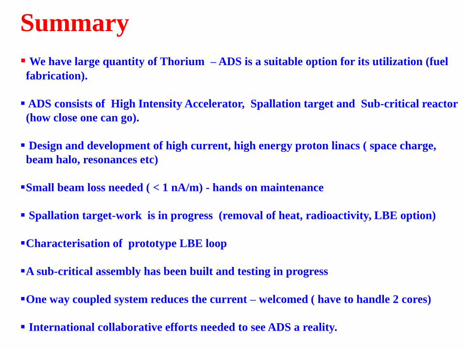
Summary
We have large quantity of Thorium – ADS is a suitable option for its utilization (fuel
fabrication).
ADS consists of High Intensity Accelerator, Spallation target and Sub-critical reactor
(how close one can go).
Design and development of high current, high energy proton linacs ( space charge,
beam halo, resonances etc)
Small beam loss needed ( < 1 nA/m) - hands on maintenance
Spallation target-work is in progress (removal of heat, radioactivity, LBE option)
Characterisation of prototype LBE loop
A sub-critical assembly has been built and testing in progress
One way coupled system reduces the current – welcomed ( have to handle 2 cores)
International collaborative efforts needed to see ADS a reality.

Acknowledgements
We thank all the members of IADD, BARC
P. Satyamurthy, BARC
S.B. Degwekar, BARC
H P Gupta, BARC
for inputs
Several institutes of DAE are contributing towards Indian
ADS program. IUAC actively involved in cavity
development- Thanks to them.

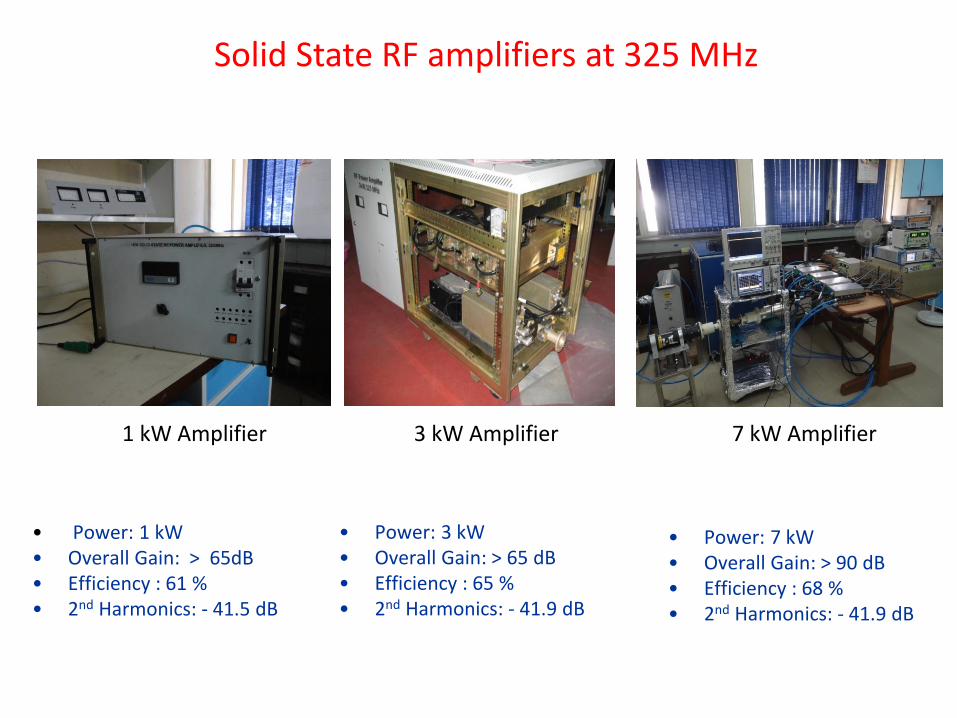
Solid State RF amplifiers at 325 MHz
• Power: 3 kW • Overall Gain: > 65 dB • Efficiency : 65 % • 2nd Harmonics: - 41.9 dB
• Power: 1 kW • Overall Gain: > 65dB • Efficiency : 61 % • 2nd Harmonics: - 41.5 dB
1 kW Amplifier 3 kW Amplifier 7 kW Amplifier
• Power: 7 kW • Overall Gain: > 90 dB • Efficiency : 68 % • 2nd Harmonics: - 41.9 dB

Solid State RF amplifier 3 kW, 325 MHz Unit
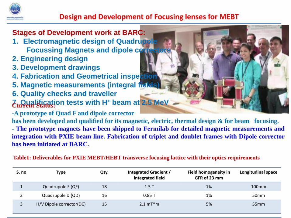
Design and Development of Focusing lenses for MEBT
S. no Type Qty. Integrated Gradient / integrated field
Field homogeneity in GFR of 23 mm
Longitudinal space
1 Quadrupole F (QF) 18 1.5 T 1% 100mm
2 Quadrupole D (QD) 16 0.85 T 1% 50mm
3 H/V Dipole corrector(DC) 15 2.1 mT*m 5% 55mm
Table1: Deliverables for PXIE MEBT/HEBT transverse focusing lattice with their optics requirements
Stages of Development work at BARC:
1. Electromagnetic design of Quadrupole
Focussing Magnets and dipole correctors
2. Engineering design
3. Development drawings
4. Fabrication and Geometrical inspection
5. Magnetic measurements (integral fields)
6. Quality checks and traveller
7. Qualification tests with H+ beam at 2.5 MeV
Current Status:
-A prototype of Quad F and dipole corrector
has been developed and qualified for its magnetic, electric, thermal design & for beam focusing.
- The prototype magnets have been shipped to Fermilab for detailed magnetic measurements and
integration with PXIE beam line. Fabrication of triplet and doublet frames with Dipole corrector
has been initiated at BARC.

Sr. no Beam Parameter Value
1. Beam H+
2. Beam energy 2.5 MeV
3. Beam Current 10nA
4. Beam size 3 mm
5. Target distance 1 meter
Qualification of dipole correctors with proton beam at FOTIA facility, BARC
Particle trajectory simulations
Dipole corrector magnet assembly installed in FOTIA beam line Steering of beam - analytical vs. measured

Wedge Tuner Installed for Testing at FNAL
66
Wedge Tuner A Double Wedge Tuner (DWT) has
been designed and developed for
compensation of Lorentz force
detuning and micro phonics
stabilization of the superconducting
RF cavities. This is a co-axial device
and can provide both the slow
structure tuning and the fast tuning
capabilities.
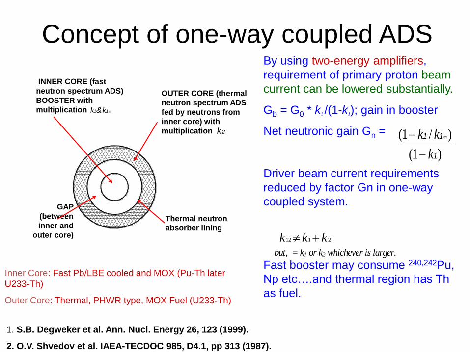
Concept of one-way coupled ADS By using two-energy amplifiers,
requirement of primary proton beam
current can be lowered substantially.
Gb = G0 * k1 /(1-k1); gain in booster
Net neutronic gain Gn =
Driver beam current requirements
reduced by factor Gn in one-way
coupled system.
Fast booster may consume 240,242Pu,
Np etc….and thermal region has Th
as fuel.
)1(
)/1(
1
11
k
kk
2112 kkk
but, = k1 or k2 whichever is larger.
INNER CORE (fast
neutron spectrum ADS)
BOOSTER with
multiplication 1 1 &kk
OUTER CORE (thermal
neutron spectrum ADS
fed by neutrons from
inner core) with
multiplication 2k
GAP
(between
inner and
outer core)
Thermal neutron
absorber lining
1. S.B. Degweker et al. Ann. Nucl. Energy 26, 123 (1999).
2. O.V. Shvedov et al. IAEA-TECDOC 985, D4.1, pp 313 (1987).
Inner Core: Fast Pb/LBE cooled and MOX (Pu-Th later
U233-Th)
Outer Core: Thermal, PHWR type, MOX Fuel (U233-Th)