Embed Size (px)
Citation preview

AFFILIATED ENGINEERS, INC. 1
COMPLEX HEATING, COOLING, AND HEAT RECOVERY PLANT MODELING
Energy Trust of Oregon
Building Energy Simulation Forum
04/18/2018
Lyle Keck, PE, LEED AP BD+C
Building Performance Consultant

AFFILIATED ENGINEERS, INC. 2
Agenda
Plant modeling basics using EnergyPlus (E+)• ‘Complex’ hydronic plant modeling
• E+ plant loop structure and equipment
• E+ plant loop controls & Energy Management System (EMS)
Simulation workflow approach
• Model setup and input file creation
• Pre/post processing, model diagnostics
Case studies• OHSU – CHH South, Block 28 & 29 (Portland, OR)
• PHSA – Teck Acute Care Centre (Vancouver, BC)
• Seattle Children’s Hospital – Building CARE (Seattle, WA)

AFFILIATED ENGINEERS, INC. 3
EnergyPlusPlant Loop Modeling
AFFILIATED ENGINEERS, INC. 4
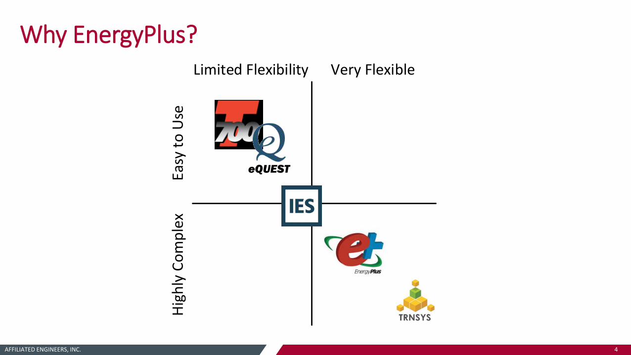
Why EnergyPlus?Limited Flexibility
Easy
to
Use
Very Flexible
Hig
hly
Co
mp
lex

AFFILIATED ENGINEERS, INC. 5
Why EnergyPlus?
Flexibility to build hydronic loops to simulate the energy performance as designed and engineered
Detailed objects for many real world equipment and components• Boilers, chillers, heat pumps
• Thermal storage tanks (HW, CHW, mixed/stratified, ice)
• Loop-to-loop objects, heat exchangers and heat pumps
Robust controls
• Many types of setpoint managers, load operation schemes
• Custom EMS controls

AFFILIATED ENGINEERS, INC. 6
Plant Loop - StructureSupply Side Demand Side
EnergyPlus has 2 main types of loops in the HVAC simulation• Air loop and plant loop
• Plant loop uses a liquid fluid as the transport medium
Each loop is broken up into 2 half-loops
• Supply side and demand side
• Demand side equipment places a load on the supply side primary equipment
• The supply side operates to meet a specific load and flow condition
• User specified rules for how that load is distributed to supply side equipment

AFFILIATED ENGINEERS, INC. 7
Plant Loop - StructureINLET OUTLET / INLET OUTLETSupply Side Demand Side
Each half-loop has an inlet and outlet
Loop pump is typically placed as first object on supply side inlet
• Placing a pump on the demand side inlet will simulate primary-secondary systems
• ‘Branch pump’ can be placed in parallel section of a branch (chiller/boiler pump, etc.)
pump
AFFILIATED ENGINEERS, INC. 8
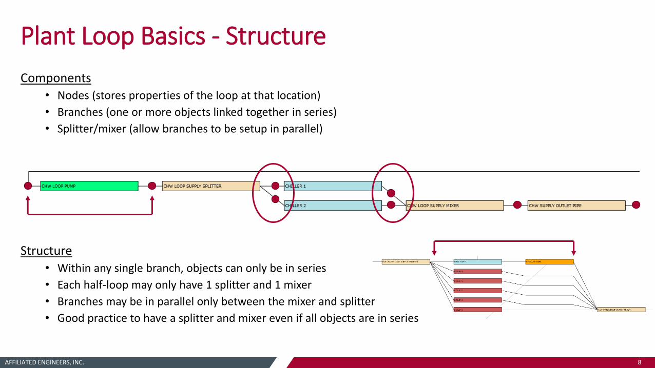
Plant Loop Basics - Structure
Components• Nodes (stores properties of the loop at that location)
• Branches (one or more objects linked together in series)
• Splitter/mixer (allow branches to be setup in parallel)
Structure• Within any single branch, objects can only be in series
• Each half-loop may only have 1 splitter and 1 mixer
• Branches may be in parallel only between the mixer and splitter
• Good practice to have a splitter and mixer even if all objects are in series

AFFILIATED ENGINEERS, INC. 9
Plant Equipment – Commonly Used Objects
Chiller:Electric:EIR
• Air-cooled or water-cooled
• Heat recovery only available with water-cooled condenser*
Boiler:HotWater
DistrictCooling
DistrictHeating

AFFILIATED ENGINEERS, INC. 10
Plant Equipment – Commonly Used Objects
HeatPump:WaterToWater• 4-pipe hydronic (hot, cold)
• Two models, EquationFit:Cooling and EquationFit:Heating
• Object only controls to one mode (heating or cooling), other mode is always passive
CentralHeatPumpSystem• 6-pipe hydronic (hot, cold, source)
• Made of multiple ChillerHeater objects
• 5 modes of operation
Heating only, cooling only, balanced heat recovery, heat recovery with trim cooling, heat recovery with trim heating
User not able to actively control mode of operation*

AFFILIATED ENGINEERS, INC. 11
Plant Equipment – Commonly Used Objects
WaterHeater:Mixed• Hot water storage tank
• Can be standalone or coupled with other objects…
• WaterHeater:HeatPump (often used to approximate plant loop air-to-water HPs by minimizing tank volume)
• Energy storage for solar hot water or waste heat recovery
ThermalStorage:ChilledWater
ThermalStorage:Ice
AFFILIATED ENGINEERS, INC. 12
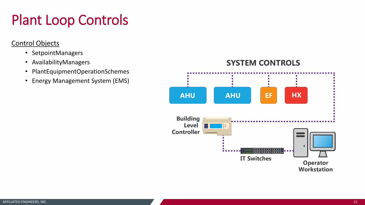
Plant Loop Controls
Control Objects• SetpointManagers
• AvailabilityManagers
• PlantEquipmentOperationSchemes
• Energy Management System (EMS)
AFFILIATED ENGINEERS, INC. 13
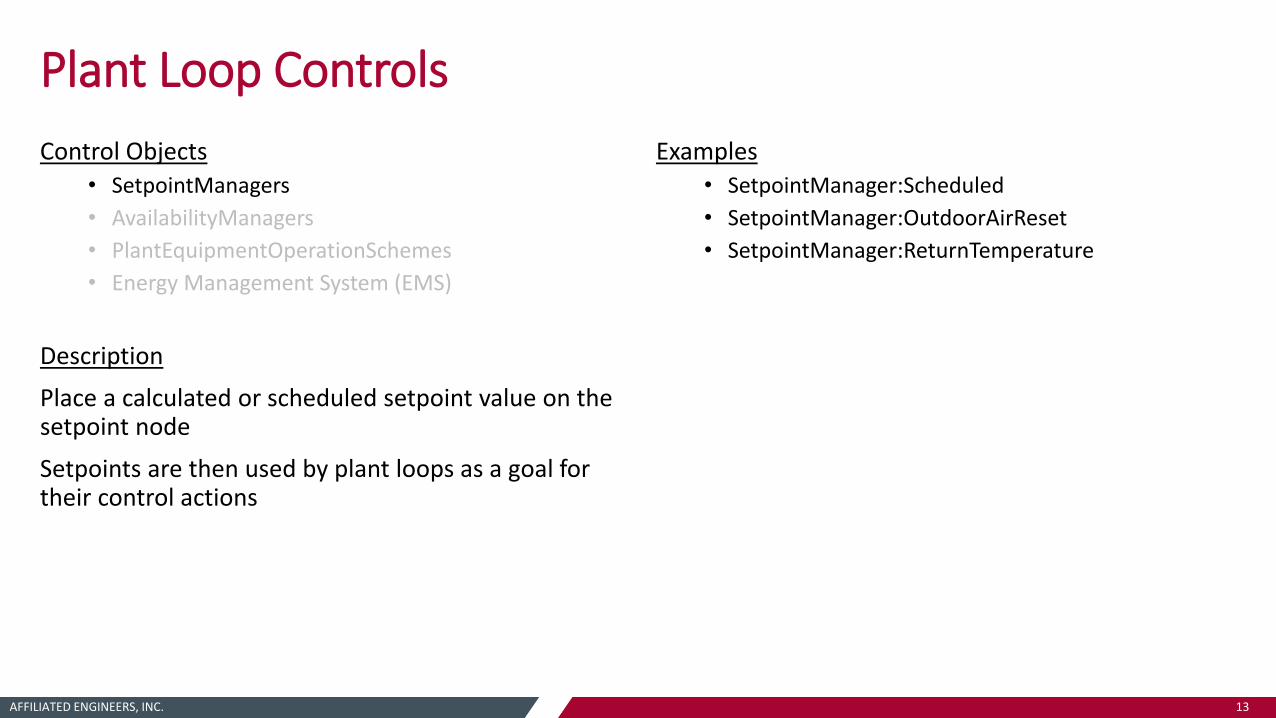
Plant Loop Controls
Control Objects• SetpointManagers
• AvailabilityManagers
• PlantEquipmentOperationSchemes
• Energy Management System (EMS)
Description
Place a calculated or scheduled setpoint value on the setpoint node
Setpoints are then used by plant loops as a goal for their control actions
Examples• SetpointManager:Scheduled
• SetpointManager:OutdoorAirReset
• SetpointManager:ReturnTemperature

AFFILIATED ENGINEERS, INC. 14
Plant Loop Controls
Control Objects• SetpointManagers
• AvailabilityManagers
• PlantEquipmentOperationSchemes
• Energy Management System (EMS)
Description
Access data from node and make a decision on whether a plant loop or equipment should be on or off
Output is an availability status flag
Loop pump then takes action of turning loop on or off – availability manager will overrule the pump on/off schedule
Examples• AvailabilityManager:Scheduled
• AvailabilityManager:DifferentialThermostat
• “ ”:High/Low Temperature Turn On/Off
AFFILIATED ENGINEERS, INC. 15
Plant Loop Controls
Control Objects• SetpointManagers
• AvailabilityManagers
• PlantEquipmentOperationSchemes
• Energy Management System (EMS)
Description
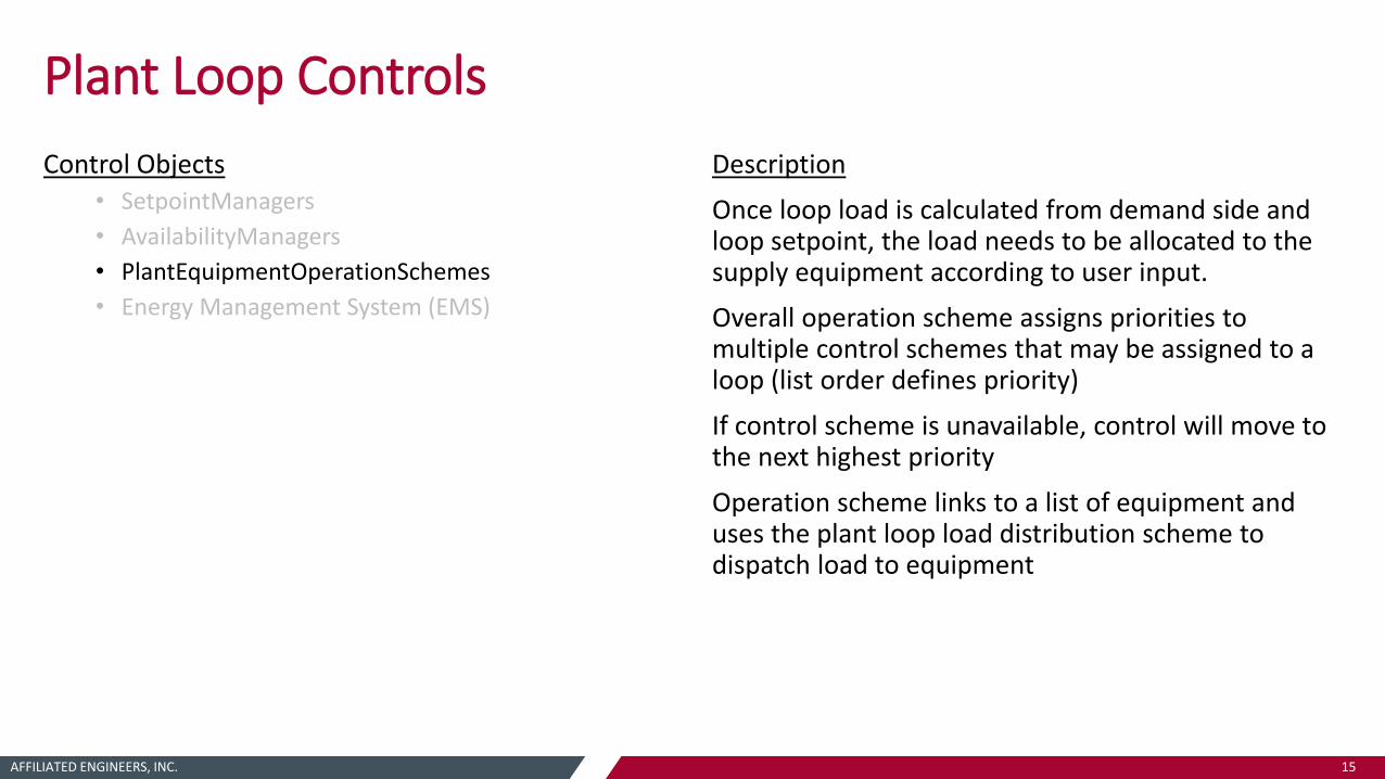
Once loop load is calculated from demand side and loop setpoint, the load needs to be allocated to the supply equipment according to user input.
Overall operation scheme assigns priorities to multiple control schemes that may be assigned to a loop (list order defines priority)
If control scheme is unavailable, control will move to the next highest priority
Operation scheme links to a list of equipment and uses the plant loop load distribution scheme to dispatch load to equipment
AFFILIATED ENGINEERS, INC. 16
Plant Loop Controls
Control Objects• SetpointManagers
• AvailabilityManagers
• PlantEquipmentOperationSchemes
• Energy Management System (EMS)
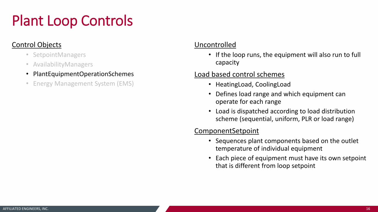
Uncontrolled• If the loop runs, the equipment will also run to full
capacity
Load based control schemes • HeatingLoad, CoolingLoad
• Defines load range and which equipment can operate for each range
• Load is dispatched according to load distribution scheme (sequential, uniform, PLR or load range)
ComponentSetpoint• Sequences plant components based on the outlet
temperature of individual equipment
• Each piece of equipment must have its own setpoint that is different from loop setpoint

AFFILIATED ENGINEERS, INC. 17
Plant Loop Controls
Control Objects• SetpointManagers
• AvailabilityManagers
• PlantEquipmentOperationSchemes
• Energy Management System (EMS)
“The Book of Erl”
Description
EMS provides a way to develop custom control and modeling routines for E+
Provides high-level supervisory control to override selected aspects of E+ simulations
Access sensor data and use this data to direct control actions
Concept is to emulate the types of control possible with DDC building automation systems in real buildings

AFFILIATED ENGINEERS, INC. 18
Plant Loop Controls - EMS
EMS:Sensor• Declares a variable. Used to get information from
somewhere else in the model to use in control calculations.
• Generally uses normal E+ output variables
EMS:Actuator
• EMS initiates control actions by changing the value of this variable.
• Actuators override things in E+. Normal operation resumes when actuator is set to Null.
• Can be scheduled value, on/off status, flow rate, load dispatch, node property, etc.
EMS:Program• Contains control logic (code) to be executed
• Uses simple if/then/else/set statements, functions and expressions to
EMS:ProgramCallingManager
• Defines when in the simulation, and/or timestep, EMS programs are executed
• Also defines when EMS programs are executed relative to other EMS programs
Global/Output/Internal Variables• Another means of accessing and reporting variables
for use in EMS

AFFILIATED ENGINEERS, INC. 19
Plant Loop Controls - EMS

AFFILIATED ENGINEERS, INC. 20
SimulationWorkflow
AFFILIATED ENGINEERS, INC. 21
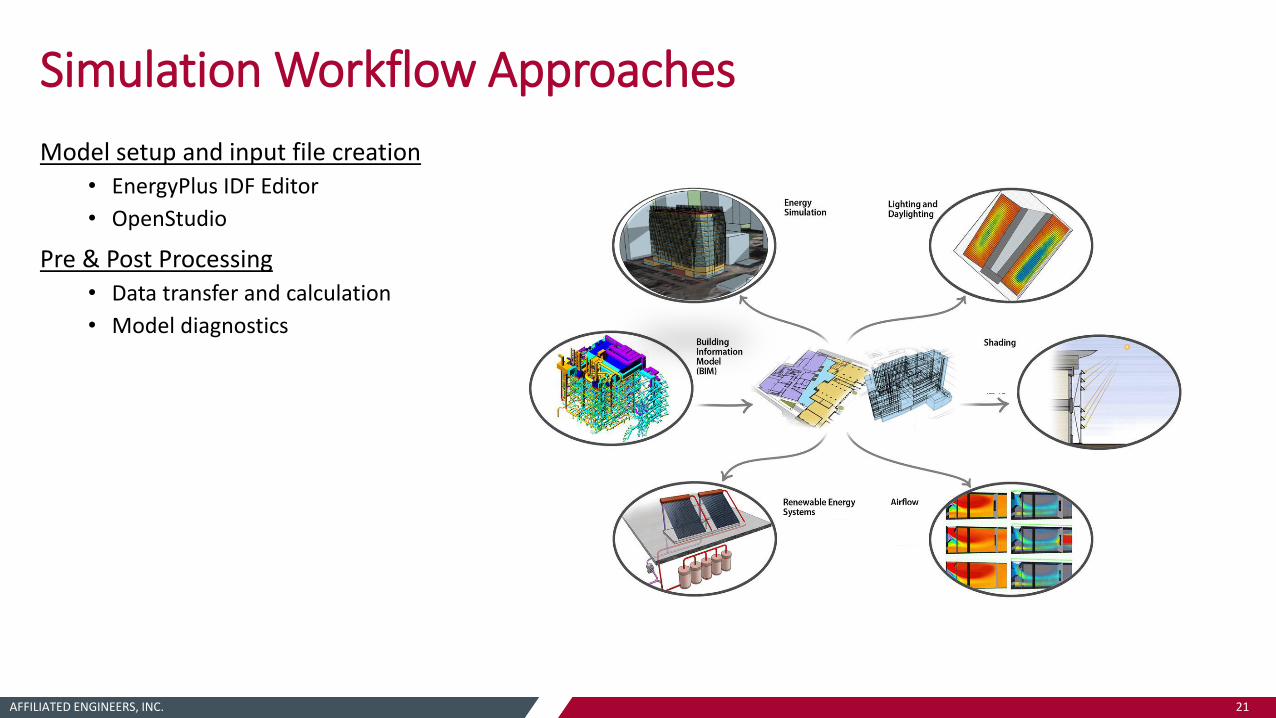
Simulation Workflow Approaches
Model setup and input file creation• EnergyPlus IDF Editor
• OpenStudio
Pre & Post Processing
• Data transfer and calculation
• Model diagnostics

AFFILIATED ENGINEERS, INC. 22
Simulation Workflow – Model Setup
EnergyPlus IDF Editor• ‘GUI’ that is distributed with E+
• No visual representation of system layout until successful setup and simulation
• Many objects to manage for each piece of equipment….
AFFILIATED ENGINEERS, INC. 23
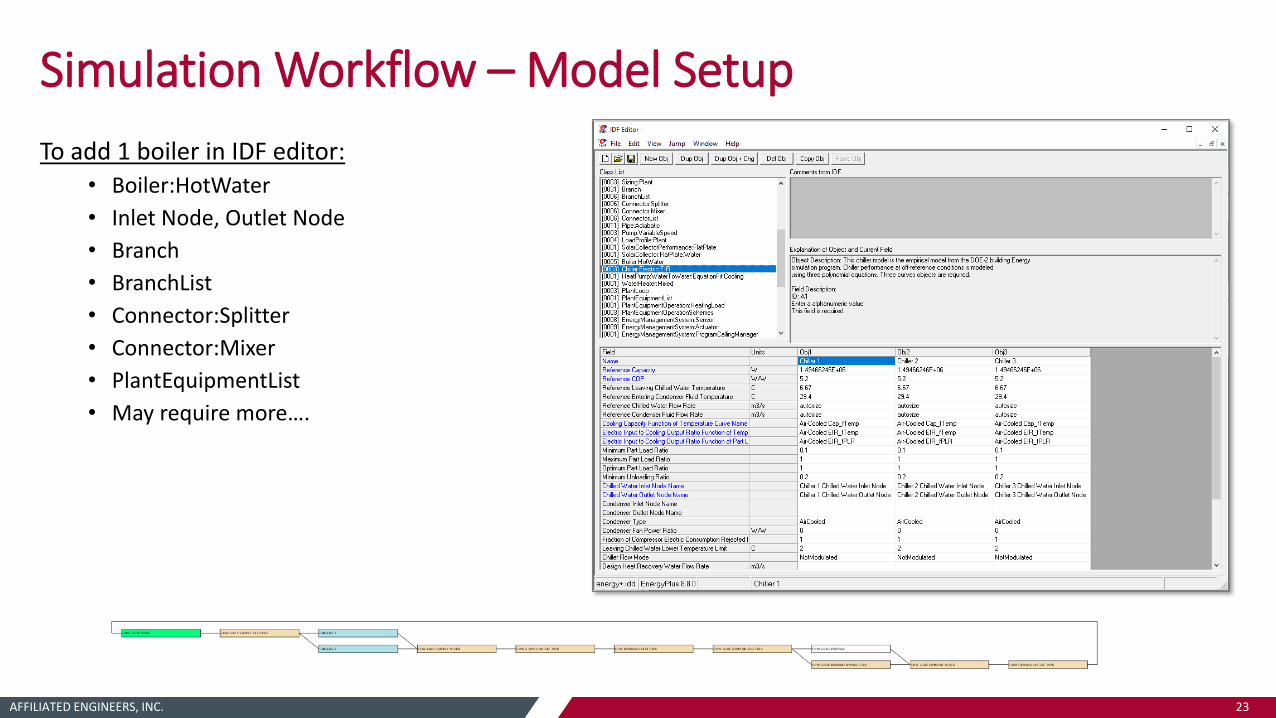
Simulation Workflow – Model Setup
To add 1 boiler in IDF editor:• Boiler:HotWater
• Inlet Node, Outlet Node
• Branch
• BranchList
• Connector:Splitter
• Connector:Mixer
• PlantEquipmentList
• May require more….

AFFILIATED ENGINEERS, INC. 24
Simulation Workflow – Model Setup
OpenStudio (OS)• Collection of tools to support
whole building modeling using E+ simulation engine
• OS Application (GUI)
• OS Software Development Kit (SDK / API)
• OS Measures (scripts)
• Other tools including SketchUp plugin for geometry, parametric analysis tool, Radiance
AFFILIATED ENGINEERS, INC. 25
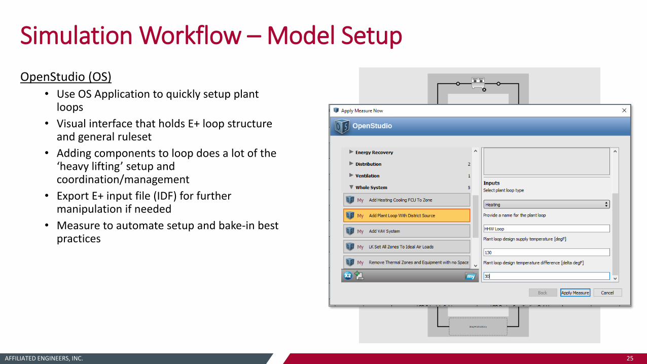
Simulation Workflow – Model Setup
OpenStudio (OS)• Use OS Application to quickly setup plant
loops
• Visual interface that holds E+ loop structure and general ruleset
• Adding components to loop does a lot of the ‘heavy lifting’ setup and coordination/management
• Export E+ input file (IDF) for further manipulation if needed
• Measure to automate setup and bake-in best practices

AFFILIATED ENGINEERS, INC. 26
Simulation Workflow – Model Setup
Custom workflows with OpenStudio API• Use OS SDK to create custom tools that quickly generate E+ plant models
AFFILIATED ENGINEERS, INC. 27
Simulation Workflow – Pre Processing
Plant model can be separate model from whole building model• Multiple buildings fed by a central district or campus plant
• OpenStudio (or other) whole building model and EnergyPlus plant model
• May be easier to setup and troubleshoot plant model in isolation, faster simulation time
• Preference and discretion of modeler
LoadProfile:Plant Object
• Used to transfer loop load/flow information from whole building model to plant model
• Can reference hourly CSV file, or reference manual schedules in E+
• Hourly data for Load [W], Flow Rate [m3/s], Flow Rate Fraction [0-1]
Create hourly variables in whole building model
Use loop design temperature difference and peak hourly load to define flow rates (peak & hourly)
Flow rate fraction is a normalized value of hourly flow rate to peak flow rate

AFFILIATED ENGINEERS, INC. 28
Simulation Workflow – Pre Processing
Data Transfer
Use custom python script to automate this process, which does the following…
• Run OS whole building simulation
• Query results file (SQL) to pull out hourly loop variables
• Calculate peak/hourly/normalized flow rates based on loop design temperature difference
• Write hourly loop information to CSV file referenced by LoadProfile:Plant object
• Run E+ plant simulation
• Query results file (SQL) and combine results from whole building model and plant model as desired

AFFILIATED ENGINEERS, INC. 29
Simulation Workflow – Post Processing
Model Diagnostics
Model results are used to ensure the model is operating as intended and support design
EnergyPlus tabular results
• HTML file and web browser
• CSV / excel
EnergyPlus hourly results• xEsoView
• DView
• CSV / excel
OpenStudio results
• E+ output files (above)
• OS application
• DView now packaged w/ OS
AFFILIATED ENGINEERS, INC. 30
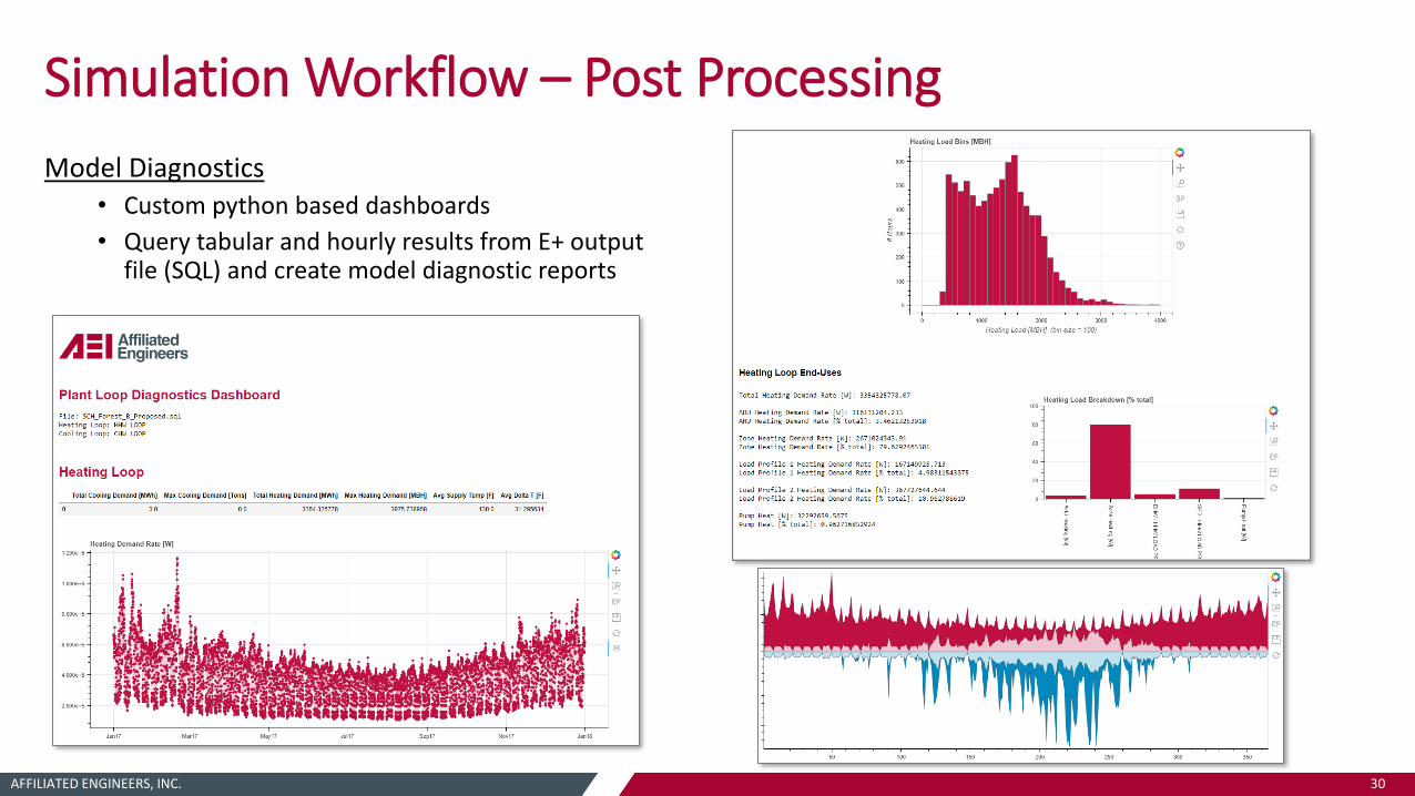
Simulation Workflow – Post Processing
Model Diagnostics• Custom python based dashboards
• Query tabular and hourly results from E+ output file (SQL) and create model diagnostic reports

AFFILIATED ENGINEERS, INC. 31
Simulation Workflow – Post Processing
Model Diagnostics• Visualize design inputs, sizing inputs & results,
tabular results and hourly data side-by-side
• Calculate key performance metrics to assess operational efficiency
• Report key metrics to inform design and write results to integrate with design workflow tools
• Intelligent sorting and binning of data
• Flexible – query model and grab appropriate results, automatically adapts to changes in number of objects & components
• Interactive – scale, zoom, hover, save image with a single click

AFFILIATED ENGINEERS, INC. 32
Plant ModelingCase Studies

AFFILIATED ENGINEERS, INC. 33
Case Studies
Oregon Health & Sciences University – Center for Health and Healing South (OHSU CHH South)• Portland, OR
• Two buildings (B28 & B29) with common central plant
• Heat recovery chiller, exhaust air heat recovery
• ETO incentive modeling
Provincial Health Services Authority – Teck Acute Care Centre (TACC)
• Vancouver, BC
• Air source heat pump
• BC Hyrdo incentive modeling
Seattle Children’s Hospital – Building CARE (SCH CARE)
• Seattle, WA
• Thermal storage
• Solar hot water collectors
AFFILIATED ENGINEERS, INC. 34
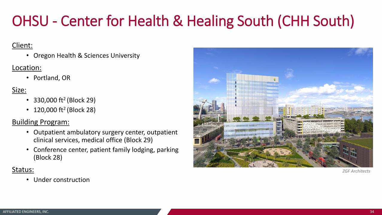
OHSU - Center for Health & Healing South (CHH South)
Client:• Oregon Health & Sciences University
Location:• Portland, OR
Size:• 330,000 ft2 (Block 29)
• 120,000 ft2 (Block 28)
Building Program:
• Outpatient ambulatory surgery center, outpatient clinical services, medical office (Block 29)
• Conference center, patient family lodging, parking (Block 28)
Status:• Under construction
ZGF Architects

AFFILIATED ENGINEERS, INC. 35
OHSU – Center For Health & Healing South
Modeling Services:• Design performance analysis
• Utility incentives (ETO)
• LEED certification
Central Plant:
Located in B29, provides HHW and CHW to B28 & B29, also provides CHW to B25 (CHH North)
• Condensing gas fired boilers
(4x) 5,600 MBH
• High efficiency water-cooled chillers & cooling towers
(2x) 1,000 ton centrifugal chillers
• Water-to-water heat recovery chillers (HRCs) w/ exhaust air heat recovery coils
(2x) 250 ton
90,000 CFM of exhaust air recovery coils
BLOCK 29
BLOCK 28
AFFILIATED ENGINEERS, INC. 36
OHSU – Center For Health & Healing South
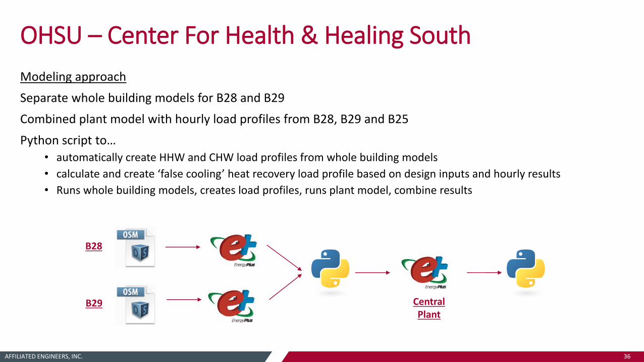
Modeling approach
Separate whole building models for B28 and B29
Combined plant model with hourly load profiles from B28, B29 and B25
Python script to…• automatically create HHW and CHW load profiles from whole building models
• calculate and create ‘false cooling’ heat recovery load profile based on design inputs and hourly results
• Runs whole building models, creates load profiles, runs plant model, combine results
Limited Flexibility
Easy
to
Use
Very Flexible
Hig
hly
Co
mp
lex
Limited FlexibilityEa
sy t
o U
seVery Flexible
Hig
hly
Co
mp
lex
Limited Flexibility
Easy
to
Use
Very Flexible
Hig
hly
Co
mp
lexB28
B29 CentralPlant

AFFILIATED ENGINEERS, INC. 37
OHSU – Center For Health & Healing South
Exhaust Air Heat Recovery w/ HRCs:• Utilize building exhaust as a heat source (70-75F)
for a super efficient form of heat pump heating
~3X more efficient than gas-fired boilers
Boiler COP = 0.9
HRC Heating COP = 3.0 - 3.5
• Capture heat leaving the building and transfer/reuse that heat at a higher grade to HHW loop
• Ability to meet preheat, reheat, and domestic water heating demands
• Operate when heating dominant:
HRC meets simultaneous heating/cooling demand first
Then engage ‘false cooling’ heat recovery coils to provide trim heating
AFFILIATED ENGINEERS, INC. 38
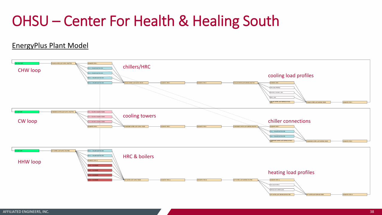
OHSU – Center For Health & Healing South
EnergyPlus Plant Model
CHW loop
CW loop
HHW loop
chillers/HRC
cooling towers
cooling load profiles
chiller connections
heating load profiles
HRC & boilers

AFFILIATED ENGINEERS, INC. 39
OHSU – Center For Health & Healing South
EnergyPlus Objects:
• Boiler:HotWater
• Chiller:Electric:EIR
• CoolingTower:VariableSpeed
• HeatPump:WaterToWater:EquationFit:Cooling
• EnergyManagementSystem:Program (and associated components)
EMS Control Logic:
• HeatPump:WaterToWater:EquationFit:Cooling only controls to cooling demand, condenser heat is passively dumped to HHW loop regardless of demand (results in overheating of loop)
• EMS is used to optimize and control HeatPump based on both CHW and HHW loop demands. Intelligently dispatch loads to HRC, chillers, and boilers.
At every time step…
• EMS reads HHW and CHW loop demands, calculates simultaneous load
• Calculates heating and cooling output of HeatPump based on load and input power at that operating point
• Determines load to be placed on HeatPump based on limiting factor (heating/cooling output)
• Calculates ‘cooling’ dispatch to HeatPump based on desired heating/cooling output
• Takes remaining HHW and CHW demands and dispatches to trim boilers and chillers

AFFILIATED ENGINEERS, INC. 40
OHSU – Center For Health & Healing South
ETO Incentive Modeling Approach:
B28 and B29 as 2 separate ETO projects
Plant savings captured under B29 project
Gas as ‘primary’ heating source with heat recovery in both models.
Baseline plant:• Boilers
• Water-cooled chillers
• Condenser water heat recovery (sized for 30% of peak heat rejection load at design conditions)
AFFILIATED ENGINEERS, INC. 41
OHSU – Center For Health & Healing South
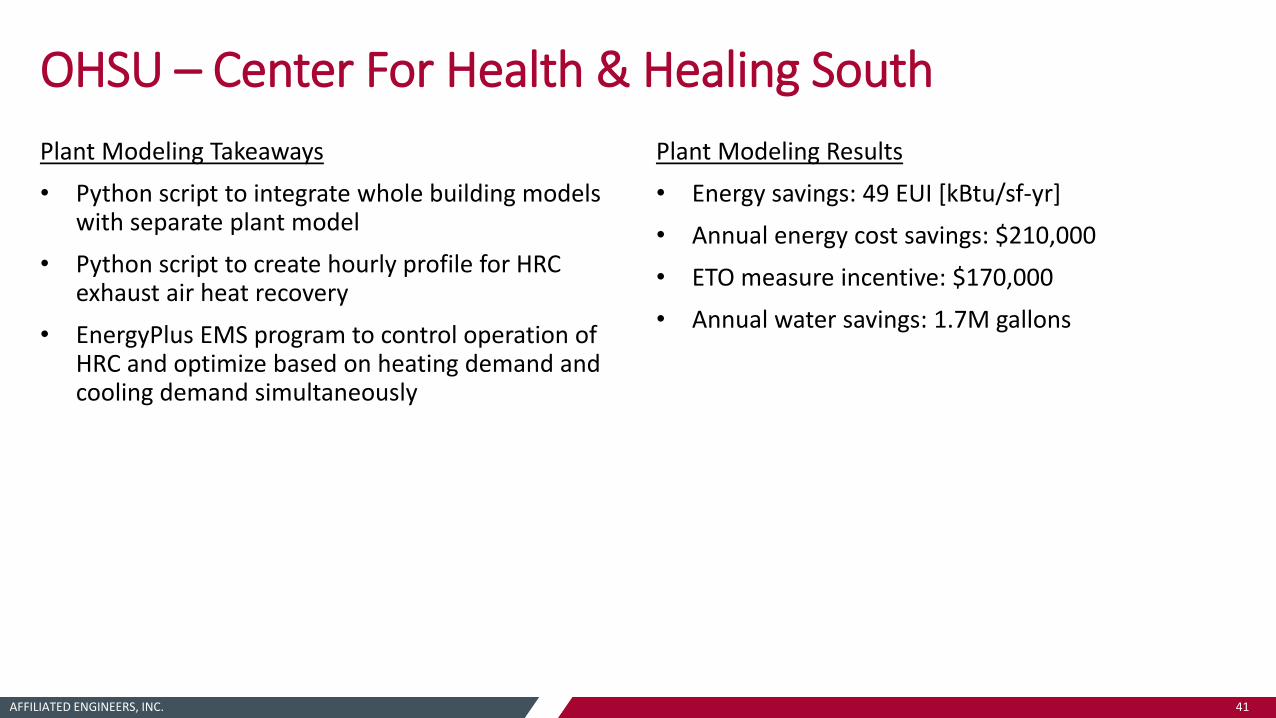
Plant Modeling Takeaways
• Python script to integrate whole building models with separate plant model
• Python script to create hourly profile for HRC exhaust air heat recovery
• EnergyPlus EMS program to control operation of HRC and optimize based on heating demand and cooling demand simultaneously
Plant Modeling Results
• Energy savings: 49 EUI [kBtu/sf-yr]
• Annual energy cost savings: $210,000
• ETO measure incentive: $170,000
• Annual water savings: 1.7M gallons
AFFILIATED ENGINEERS, INC. 42
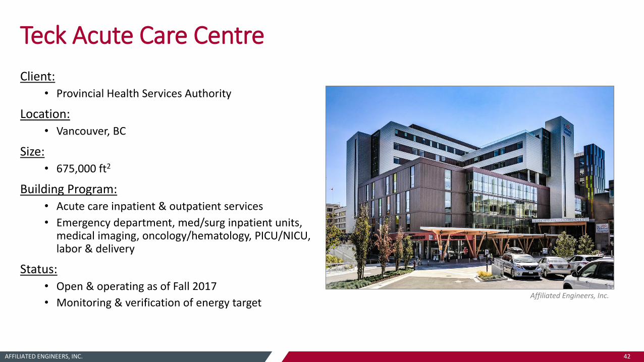
Teck Acute Care Centre
Client:• Provincial Health Services Authority
Location:• Vancouver, BC
Size:• 675,000 ft2
Building Program: • Acute care inpatient & outpatient services
• Emergency department, med/surg inpatient units, medical imaging, oncology/hematology, PICU/NICU, labor & delivery
Status:
• Open & operating as of Fall 2017
• Monitoring & verification of energy targetAffiliated Engineers, Inc.
AFFILIATED ENGINEERS, INC. 43
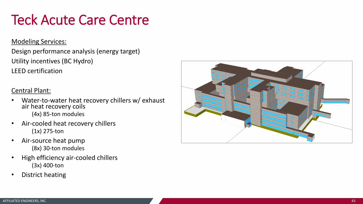
Teck Acute Care Centre
Modeling Services:
Design performance analysis (energy target)
Utility incentives (BC Hydro)
LEED certification
Central Plant:
• Water-to-water heat recovery chillers w/ exhaust air heat recovery coils
(4x) 85-ton modules
• Air-cooled heat recovery chillers(1x) 275-ton
• Air-source heat pump(8x) 30-ton modules
• High efficiency air-cooled chillers(3x) 400-ton
• District heating
AFFILIATED ENGINEERS, INC. 44
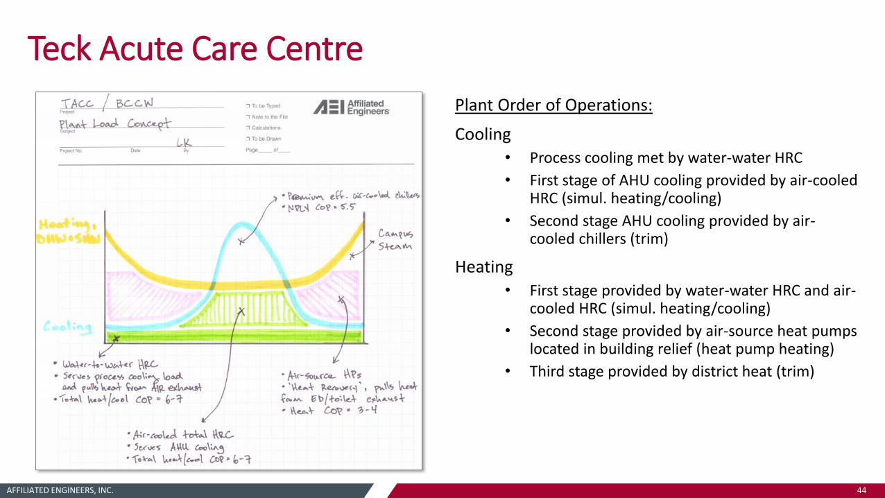
Teck Acute Care Centre
Plant Order of Operations:
Cooling• Process cooling met by water-water HRC
• First stage of AHU cooling provided by air-cooled HRC (simul. heating/cooling)
• Second stage AHU cooling provided by air-cooled chillers (trim)
Heating
• First stage provided by water-water HRC and air-cooled HRC (simul. heating/cooling)
• Second stage provided by air-source heat pumps located in building relief (heat pump heating)
• Third stage provided by district heat (trim)

AFFILIATED ENGINEERS, INC. 45
Teck Acute Care Centre
EnergyPlus Plant Model:
CHW loop
Process CHW loop
Heat recovery loop
HHW loop
Air-source HP
air-cooled HRC
air-cooled chillers
water-water HRC
CHW load profile
process CHW load profile
heat exchanger
HHW load profileheat recovery heat exchanger, boilers

AFFILIATED ENGINEERS, INC. 46
Teck Acute Care Centre
EnergyPlus Objects:
• District:Heating
• Chiller:Electric:EIR
• HeatPump:WaterToWater:EquationFit:Cooling
• WaterHeater:Mixed
• WaterHeater:HeatPump:PumpedCondenser
• Coil:WaterHeating:AirToWaterHeatPump:Pumped
• HeatExchanger:FluidToFluid
• EnergyManagementSystem:Program (and associated components)
WaterHeater:Mixed Object:
Used to approximate air-to-water heat pumps located in building relief airstream*
• Set storage tank volume to 1 gallon (virtually no thermal storage)
• Use heat pump with air-to-water coil
• Schedule evaporator nodes of heat pump coil to equal relief air conditions
*native EnergyPlus air-to-water HP is only for Zone HVAC use, not plant loop

AFFILIATED ENGINEERS, INC. 47
Teck Acute Care Centre
BC Hydro Incentive Modeling Approach:
Unique methodology to baseline plant regarding fuel switching
• Baseline heating plant includes a mix of electric air-to-water heat pumps and gas-fired boilers (matches fuel source mix of proposed heating equipment)
• Baseline heat pumps sized and controlled to match the proportion of annual load met by electricity vs. gas in the proposed model.
Great energy modeling guidelines including detailed modeling procedures and equipment performance tables that are not well defined in reference codes/standards

AFFILIATED ENGINEERS, INC. 48
Teck Acute Care Centre
Plant Modeling Takeaways
• Use of WaterHeater:Mixed object to approximate air-to-water heat pumps connected to plant loop
• For complex equipment control and heat recovery, consider using a separate plant loop as intermediate between CHW and HHW loops
• Innovative approach to fuel switching and baseline heating plant modeling for BC Hydro
Plant Modeling Results
• Annual energy cost savings: $185,000
• BC Hydro measure incentive: $600,000

AFFILIATED ENGINEERS, INC. 49
Seattle Children’s Hospital – Building CARE
Client:• Seattle Children’s Hospital
Location:• Seattle, WA
Size:• 300,000 ft2
Building Program: • Acute care inpatient & outpatient services
• Operating rooms/interventional suites, diagnostic and therapeutic services, inpatient unit, ambulatory clinics, infusion, sterile processing, admin/support
Status:
• In designZGF Architects

AFFILIATED ENGINEERS, INC. 50
Seattle Children’s Hospital – Building CARE
Modeling Services:
Design performance analysis (energy target)
Code compliance (City of Seattle)
Utility incentives (SCL/PSE)
LEED certification
Central Plant:• Water-to-water heat recovery chillers
w/ exhaust air heat recovery coils(1x) 250-ton
• Air-cooled chillers(5x) 525-ton
• Solar thermal array & HW storage(95) Evacuated tube collectors
(4x) 1,250 gallon HW storage tanks
• Condensing gas-fired boilers(5x) 3,400 MBH

AFFILIATED ENGINEERS, INC. 51
Seattle Children’s Hospital – Building CARE
CHW loop
HHW loop
Solar HW loop
water-water HRC
air-cooled chillers
HW storage tanks solar HW collectors
HW storage tank
water-water HRC
boilers
cooling load profiles
heating load profiles
EnergyPlus Plant Model:
AFFILIATED ENGINEERS, INC. 52
Seattle Children’s Hospital – Building CARE
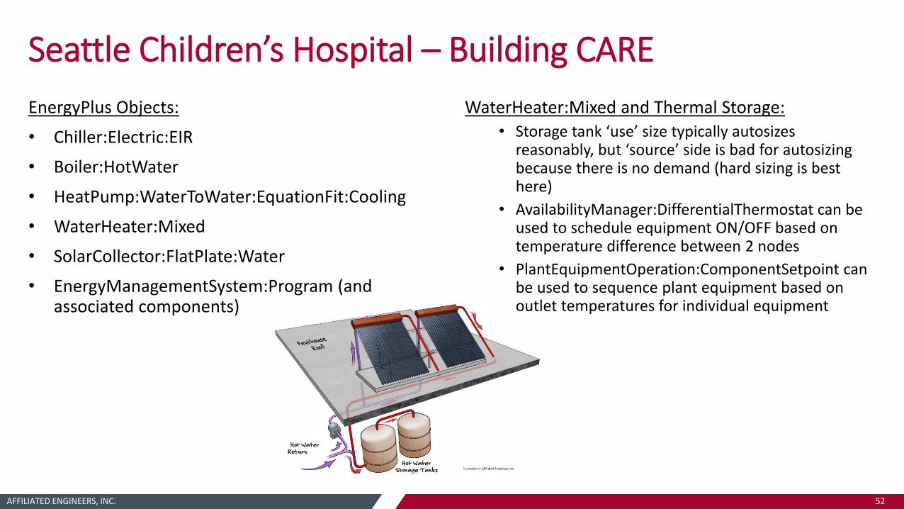
EnergyPlus Objects:
• Chiller:Electric:EIR
• Boiler:HotWater
• HeatPump:WaterToWater:EquationFit:Cooling
• WaterHeater:Mixed
• SolarCollector:FlatPlate:Water
• EnergyManagementSystem:Program (and associated components)
WaterHeater:Mixed and Thermal Storage:• Storage tank ‘use’ size typically autosizes
reasonably, but ‘source’ side is bad for autosizing because there is no demand (hard sizing is best here)
• AvailabilityManager:DifferentialThermostat can be used to schedule equipment ON/OFF based on temperature difference between 2 nodes
• PlantEquipmentOperation:ComponentSetpoint can be used to sequence plant equipment based on outlet temperatures for individual equipment

AFFILIATED ENGINEERS, INC. 53
Heating Demand
Cooling Demand
Heating Demand (Trim)
Simultaneous Demand
Cooling Demand (Trim)
Simultaneous Demand

AFFILIATED ENGINEERS, INC. 54
Boilers
HRC: Simultaneous Heat/Cool
Air-Cooled Chillers
HRC: ‘False Cooling’ Heat Recovery
Solar Water Heating
HRC: Simultaneous Heat/Cool
Air-Cooled Chillers
Boilers
AFFILIATED ENGINEERS, INC. 55
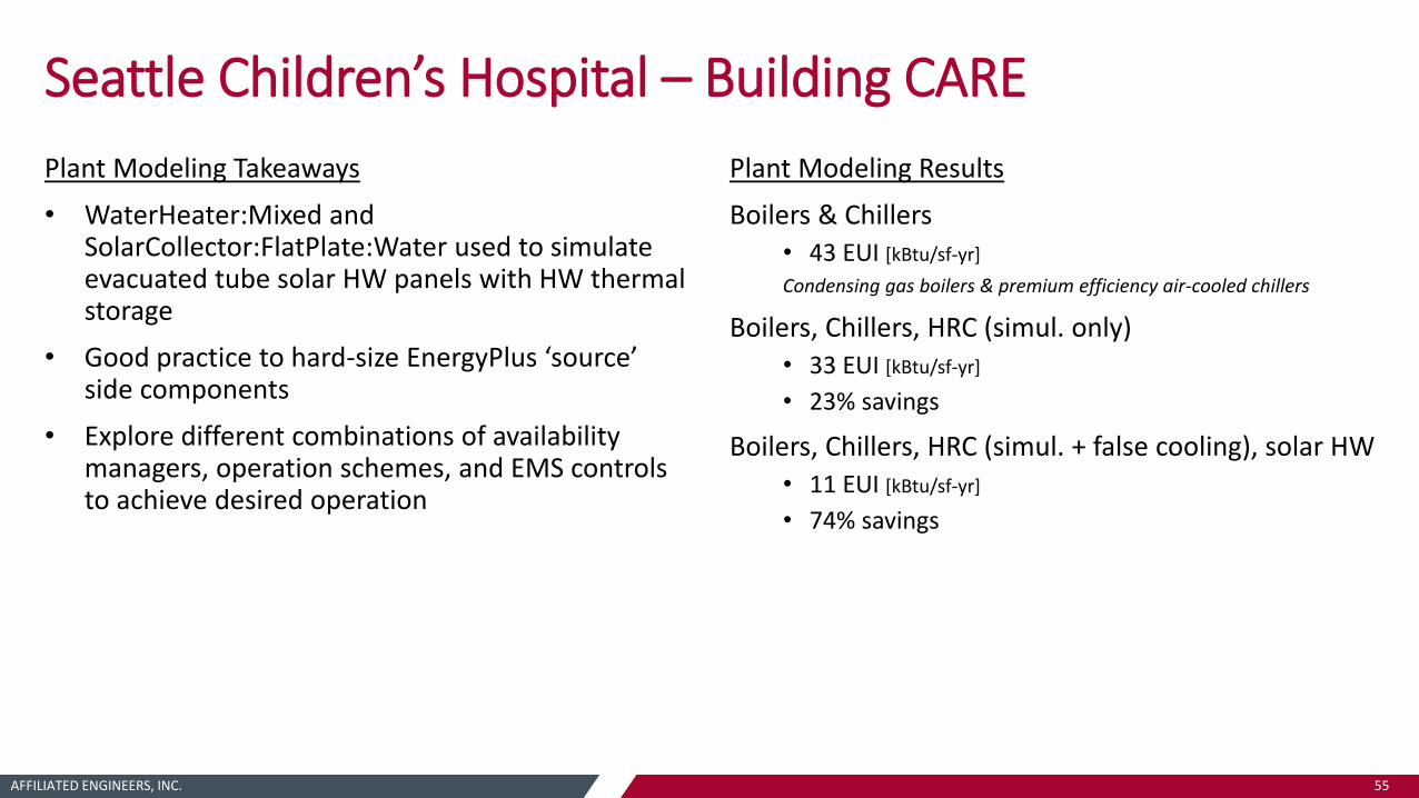
Seattle Children’s Hospital – Building CARE
Plant Modeling Takeaways
• WaterHeater:Mixed and SolarCollector:FlatPlate:Water used to simulate evacuated tube solar HW panels with HW thermal storage
• Good practice to hard-size EnergyPlus ‘source’ side components
• Explore different combinations of availability managers, operation schemes, and EMS controls to achieve desired operation
Plant Modeling Results
Boilers & Chillers • 43 EUI [kBtu/sf-yr]
Condensing gas boilers & premium efficiency air-cooled chillers
Boilers, Chillers, HRC (simul. only)• 33 EUI [kBtu/sf-yr]
• 23% savings
Boilers, Chillers, HRC (simul. + false cooling), solar HW
• 11 EUI [kBtu/sf-yr]
• 74% savings

AFFILIATED ENGINEERS, INC. 56
QUESTIONS?
Lyle Keck, PE, LEED AP BD+C
aeieng.com
AEI/Affiliated Engineers, Inc.
@AEITweets