Embed Size (px)
Citation preview
Complete Teardown, Cleaning, and Reassembly of the Olympus BH2-BI30 Binocular Viewing Head (Rev. 1) Page 1 of 34
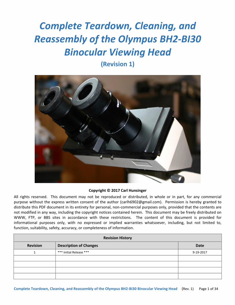
Complete Teardown, Cleaning, and Reassembly of the Olympus BH2-BI30
Binocular Viewing Head (Revision 1)
Copyright © 2017 Carl Hunsinger
All rights reserved. This document may not be reproduced or distributed, in whole or in part, for any commercial purpose without the express written consent of the author ([email protected]). Permission is hereby granted to distribute this PDF document in its entirety for personal, non-commercial purposes only, provided that the contents are not modified in any way, including the copyright notices contained herein. This document may be freely distributed on WWW, FTP, or BBS sites in accordance with these restrictions. The content of this document is provided for informational purposes only, with no expressed or implied warranties whatsoever, including, but not limited to, function, suitability, safety, accuracy, or completeness of information.
Revision History
Revision Description of Changes Date
1 *** Initial Release *** 9-19-2017

Complete Teardown, Cleaning, and Reassembly of the Olympus BH2-BI30 Binocular Viewing Head (Rev. 1) Page 2 of 34
Table of Contents Introduction ............................................................................................................................................................................ 7 Scope of this Document .......................................................................................................................................................... 7 Before Attempting Your Own Service ..................................................................................................................................... 7 Common Problems with the BH2-BI30 Head .......................................................................................................................... 7
Interocular-Distance Slide is Stiff or Seized ........................................................................................................................ 7 Focus Ring on Left-Hand Ocular Tube is Stiff or Seized ...................................................................................................... 7 Internal Optics are Dirty ...................................................................................................................................................... 7 Optical Alignment is Poor ................................................................................................................................................... 8
Left-Hand and Right-Hand Side Designations ......................................................................................................................... 8 Tools Needed .......................................................................................................................................................................... 8 Electric Heat Gun .................................................................................................................................................................... 8 A Few Words about JIS Screws ............................................................................................................................................... 8 Disassembling the BH2-BI30 Viewing Head ............................................................................................................................ 8 Supplies Needed ..................................................................................................................................................................... 9 Recommended Solvents ......................................................................................................................................................... 9 Safety Considerations with Solvents ....................................................................................................................................... 9 Solvent Compatibility with Parts and Finishes ........................................................................................................................ 9 Recommended Lubricants ...................................................................................................................................................... 9 Label Parts for Identification and Reassembly ........................................................................................................................ 9 Servicing the BH2-BI30 Binocular Viewing Head .................................................................................................................... 9
Remove the Helical Focus Ring (Left) ................................................................................................................................ 10 Remove the Plastic Finger Grip (Left) ............................................................................................................................... 10 Remove the Plastic Finger Grip (Right) ............................................................................................................................. 11 Remove the Graduated Center Cover ............................................................................................................................... 11 Remove the Frame Assembly from the Main Housing ..................................................................................................... 12 Remove Mounting Disk Assembly from Main Housing .................................................................................................... 12 Reinstall Mounting Disk Assembly onto Main Housing .................................................................................................... 13 Remove the Tension Springs for the Follower Keys ......................................................................................................... 13 Remove the Follower Keys ................................................................................................................................................ 14 Clean Inner Tubes and Regrease the Helical Focus Ring................................................................................................... 14 Remove the Ocular Slide Assembly (Left) ......................................................................................................................... 17 Remove the Ocular Slide Assembly (Right) ....................................................................................................................... 18 Remove the Brass Pivot Lever ........................................................................................................................................... 18 Clean the Various Mechanical Parts ................................................................................................................................. 19 Remove the P3/P4 Prism Mount ...................................................................................................................................... 20 Reinstall the P3/P4 Prism Mount ...................................................................................................................................... 21 Clean the Various Optical Components ............................................................................................................................ 21 Lubricate the Various Slide Parts ...................................................................................................................................... 23 Reinstall the Ocular Slide Assembly (Left) ........................................................................................................................ 25 Reinstall the Ocular Slide Assembly (Right) ...................................................................................................................... 26 Grease the Follower-Key Slots in the Front Frame ........................................................................................................... 27 Reinstall the Follower Keys ............................................................................................................................................... 27 Reinstall the Tension Springs for the Follower Keys ......................................................................................................... 27 Reinstall the Frame Assembly into the Main Housing ...................................................................................................... 29 Reinstall the Graduated Center Plate ............................................................................................................................... 29 Reinstall the Plastic Finger Grips ....................................................................................................................................... 30 Reinstall the Helical Focus Ring (Left) – Most Accurate .................................................................................................... 31 Reinstall the Helical Focus Ring (Left) – Less Accurate ..................................................................................................... 32 Reinstall the Black Trim Ring for Ocular Tube (Right) ....................................................................................................... 32
Ready for Service .................................................................................................................................................................. 33

Complete Teardown, Cleaning, and Reassembly of the Olympus BH2-BI30 Binocular Viewing Head (Rev. 1) Page 3 of 34
Original Olympus Documentation ........................................................................................................................................ 33 How to Contact the Author ................................................................................................................................................... 33 Appendix 1 ............................................................................................................................................................................ 34 Sources for Replacement Tools and Supplies Referenced in this Document ....................................................................... 34
Table of Figures Figure 1 – The Jentsch style BH2-BI30 viewing head .............................................................................................................. 7
Figure 2 – Head of a typical JIS screw ..................................................................................................................................... 8
Figure 3 – Loosen set screws securing helical focus ring (left) ............................................................................................. 10
Figure 4 – Remove helical focus ring from ocular tube (left) ............................................................................................... 10
Figure 5 – Screws securing finger grip to the slide (left) ....................................................................................................... 10
Figure 6 – Remove screws securing finger grip (left) ............................................................................................................ 10
Figure 7 – Remove front screw from finger grip (left) .......................................................................................................... 10
Figure 8 – Remove finger grip from ocular tube (left) .......................................................................................................... 10
Figure 9 – Screws securing finger grip to slide (right) ........................................................................................................... 11
Figure 10 – Remove screws securing finger grip (right) ........................................................................................................ 11
Figure 11 – Remove front screw from finger grip (right) ...................................................................................................... 11
Figure 12 – Remove finger grip from ocular tube (right) ...................................................................................................... 11
Figure 13 – Remove screws securing center cover (top) ...................................................................................................... 11
Figure 14 – Remove screws securing center cover (bottom) ............................................................................................... 11
Figure 15 – Remove the center cover from the frame ......................................................................................................... 12
Figure 16 – Screws securing front frame to the main housing ............................................................................................. 12
Figure 17 – Remove screws securing front frame to housing .............................................................................................. 12
Figure 18 – Remove frame assembly from main housing..................................................................................................... 12
Figure 19 – Apply tape to mark placement of mounting disk............................................................................................... 12
Figure 20 – Remove screws securing mounting disk assembly ............................................................................................ 12
Figure 21 – Remove the mounting disk assembly ................................................................................................................ 13
Figure 22 – The mounting disk assembly .............................................................................................................................. 13
Figure 23 – Place the mounting disk assembly into position ................................................................................................ 13
Figure 24 – Secure the mounting disk assembly in position ................................................................................................. 13
Figure 25 – The tensions springs for the follower keys ........................................................................................................ 13
Figure 26 – Relieve the pre-load on the straight spring ....................................................................................................... 13
Figure 27 – Remove the screw securing the straight spring ................................................................................................. 14
Figure 28 – Remove the straight spring ................................................................................................................................ 14
Figure 29 – Remove the screw securing the bent spring ...................................................................................................... 14
Figure 30 – Remove the bent spring ..................................................................................................................................... 14
Figure 31 – Remove the follower key (right) ........................................................................................................................ 14
Figure 32 – Remove the follower key (left) .......................................................................................................................... 14
Figure 33 – Remove helical/polished inner tubes (left) ........................................................................................................ 15
Figure 34 – Remove grease from inner tube (left) ............................................................................................................... 15
Figure 35 – Unscrew helical tube from the inner tube (left) ................................................................................................ 15
Figure 36 – Clean old grease from the outer helicoid threads ............................................................................................. 15
Figure 37 – Clean grease from threads of inner tube (left) .................................................................................................. 15
Figure 38 – Apply fresh grease to the outer helicoid threads .............................................................................................. 15
Figure 39 – Apply fresh grease to inner helicoid threads (left) ............................................................................................ 16
Figure 40 – Thread the helical tube into the inner tube (left) .............................................................................................. 16
Figure 41 – Remove grease from the ocular tube (left) ........................................................................................................ 16

Complete Teardown, Cleaning, and Reassembly of the Olympus BH2-BI30 Binocular Viewing Head (Rev. 1) Page 4 of 34
Figure 42 – Reinstall the inner / helical tubes (left) .............................................................................................................. 16
Figure 43 – Remove black trim ring from ocular tube (right) ............................................................................................... 16
Figure 44 – Remove the fixed sleeve/inner tubes (right) ..................................................................................................... 16
Figure 45 – Remove grease from the inner tube (right) ....................................................................................................... 17
Figure 46 – Remove grease from the ocular tube (right) ..................................................................................................... 17
Figure 47 – Reinstall the fixed sleeve / inner tube (right) .................................................................................................... 17
Figure 48 – Remove screws securing dovetail block (left) .................................................................................................... 17
Figure 49 – Remove dovetail block from the frame (left) .................................................................................................... 17
Figure 50 – Remove the ocular slide assembly (left) ............................................................................................................ 17
Figure 51 – The ocular slide assembly (left) .......................................................................................................................... 18
Figure 52 – Remove screws securing dovetail block (right) .................................................................................................. 18
Figure 53 – Remove dovetail block from frame (right) ......................................................................................................... 18
Figure 54 – Remove the ocular slide assembly (right) .......................................................................................................... 18
Figure 55 – The ocular slide assembly (right) ....................................................................................................................... 18
Figure 56 – Remove screw holding brass pivot lever in place .............................................................................................. 18
Figure 57 – Remove brass pivot lever from the frame ......................................................................................................... 19
Figure 58 – Clean old grease from the brass pivot lever ...................................................................................................... 19
Figure 59 – Clean grease from pivot-lever bearing surface .................................................................................................. 19
Figure 60 – Clean grease from the lower dovetail bevels ..................................................................................................... 19
Figure 61 – Clean old grease from upper sliding surfaces .................................................................................................... 19
Figure 62 – Clean old grease from bevels of slide (right) ..................................................................................................... 19
Figure 63 – Clean old grease from bevels of slide (left) ........................................................................................................ 20
Figure 64 – Clean old grease from back of slide (right) ........................................................................................................ 20
Figure 65 – Clean old grease from back of slide (left) .......................................................................................................... 20
Figure 66 – Clean old grease from both dovetail blocks ....................................................................................................... 20
Figure 67 – Remove screws securing the P3/P4 prism mount ............................................................................................. 20
Figure 68 – Remove P3/P4 prism mount with prisms .......................................................................................................... 20
Figure 69 – The P3/P4 prism mount with P3 and P4 prisms ................................................................................................. 21
Figure 70 – Place P3/P4 prism mount into position on frame .............................................................................................. 21
Figure 71 – Reinstall screws to secure P3/P4 prism mount .................................................................................................. 21
Figure 72 – Clean face of prism P1 in mounting dovetail ..................................................................................................... 21
Figure 73 – Clean the face of P2 prism in the main housing ................................................................................................. 21
Figure 74 – Clean three faces of P3/P4 prisms (view 1) ....................................................................................................... 22
Figure 75 – Clean three faces of P3/P4 prisms (view 2) ....................................................................................................... 22
Figure 76 – Remove sleeve/inner tube from ocular tube (right) .......................................................................................... 22
Figure 77 – Clean face 1 of the P5 prism (right) .................................................................................................................... 22
Figure 78 – Clean face 2 of the P5 prism (right) .................................................................................................................... 22
Figure 79 – Lightly grease polished inner tube (right) .......................................................................................................... 22
Figure 80 – Reinstall inner tube/sleeve into ocular tube (right) ........................................................................................... 23
Figure 81 – Remove helical/inner tubes from ocular tube (left) .......................................................................................... 23
Figure 82 – Clean face 1 of the P6 prism (left) ...................................................................................................................... 23
Figure 83 – Clean face 2 of the P6 prism (left) ...................................................................................................................... 23
Figure 84 – Lightly grease the polished inner tube (left) ...................................................................................................... 23
Figure 85 – Reinstall helical/inner tubes into ocular tube (left) ........................................................................................... 23
Figure 86 – Apply grease to lower dovetail bevels of frame ................................................................................................ 24
Figure 87 – Apply grease to upper sliding surfaces of frame ................................................................................................ 24
Figure 88 – Apply grease to pivot-lever bearing surface of frame ....................................................................................... 24

Complete Teardown, Cleaning, and Reassembly of the Olympus BH2-BI30 Binocular Viewing Head (Rev. 1) Page 5 of 34
Figure 89 – Apply grease to the hole and slots in pivot lever ............................................................................................... 24
Figure 90 – Embed brass pivot lever into grease on the frame ............................................................................................ 24
Figure 91 – Reinstall pivot-shaft screw to secure pivot lever ............................................................................................... 24
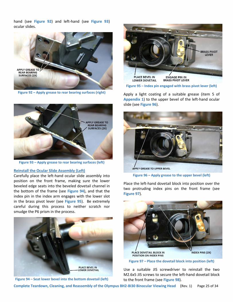
Figure 92 – Apply grease to rear bearing surfaces (right)..................................................................................................... 25
Figure 93 – Apply grease to rear bearing surfaces (left) ....................................................................................................... 25
Figure 94 – Seat lower bevel into the bottom dovetail (left) ............................................................................................... 25
Figure 95 – Index pin engaged with brass pivot lever (left) .................................................................................................. 25
Figure 96 – Apply grease to the upper bevel (left) ............................................................................................................... 25
Figure 97 – Place the dovetail block into position (left) ....................................................................................................... 25
Figure 98 – Reinstall screws to secure dovetail block (left) .................................................................................................. 26
Figure 99 – Seat lower bevel into bottom dovetail (right).................................................................................................... 26
Figure 100 – Index pin engaged with brass pivot lever (right) ............................................................................................. 26
Figure 101 – Apply grease to the upper bevel (right) ........................................................................................................... 26
Figure 102 – Place the dovetail block into position (right) ................................................................................................... 26
Figure 103 – Reinstall screws to secure dovetail block (right) .............................................................................................. 26
Figure 104 – Grease two slots in the top of front frame ...................................................................................................... 27
Figure 105 – Position ocular slide to center hole in slot (left) .............................................................................................. 27
Figure 106 – Reinstall the follower key into the slot (left) ................................................................................................... 27
Figure 107 – Position ocular tube to center hole in slot (right) ............................................................................................ 27
Figure 108 – Reinstall the follower key into the slot (right) ................................................................................................. 27
Figure 109 – Hook straight spring over follower key (right) ................................................................................................. 27
Figure 110 – Align coil of straight spring with hole (right) .................................................................................................... 28
Figure 111 – Secure the straight spring with screw (right) ................................................................................................... 28
Figure 112 – Hook bent spring over follower key (left) ........................................................................................................ 28
Figure 113 – Align coil of bent spring with hole (left) ........................................................................................................... 28
Figure 114 – Secure the bent spring with screw (left) .......................................................................................................... 28
Figure 115 – Pre-load the two tension springs ..................................................................................................................... 28
Figure 116 – Slide the frame assembly into the main housing ............................................................................................. 29
Figure 117 – Position frame so holes line up with housing .................................................................................................. 29
Figure 118 – Secure frame assembly into the main housing ................................................................................................ 29
Figure 119 – Spread the two ocular tubes apart .................................................................................................................. 29
Figure 120 – Position center plate to align with holes in frame ........................................................................................... 29
Figure 121 – Secure the plate with two screws (top) ........................................................................................................... 29
Figure 122 – Secure the plate with two screws (bottom)..................................................................................................... 30
Figure 123 – Set the ocular tubes to their maximum spacing .............................................................................................. 30
Figure 124 – Place the finger grip into position (left) ........................................................................................................... 30
Figure 125 – Reinstall front screw into the finger grip (left) ................................................................................................ 30
Figure 126 – Reinstall back screws into the finger grip (left) ................................................................................................ 30
Figure 127 – Place the finger grip into position (right) ......................................................................................................... 30
Figure 128 – Reinstall front screw into the finger grip (right) .............................................................................................. 31
Figure 129 – Reinstall back screws into the finger grip (right) ............................................................................................. 31
Figure 130 – Place helical focus ring onto ocular tube (left) ................................................................................................ 31
Figure 131 – Tighten set screws to secure helical focus ring ................................................................................................ 31
Figure 132 – Loosen set screws securing helical focus ring .................................................................................................. 32
Figure 133 – Align the zero-diopter marking with white dot ............................................................................................... 32
Figure 134 – Adjust helical focus tube for equal tube lengths ............................................................................................. 32
Figure 135 – Apply spots of adhesive to ocular tube (right) ................................................................................................. 32

Complete Teardown, Cleaning, and Reassembly of the Olympus BH2-BI30 Binocular Viewing Head (Rev. 1) Page 6 of 34
Figure 136 – Place trim ring over the ocular tube (right) ..................................................................................................... 33
Figure 137 – Press trim ring into adhesive to seat it (right) ................................................................................................. 33
Figure 138 – The Olympus BH2-BI30 repair manual ............................................................................................................. 33
Figure 139 – The Olympus BH2 (BHS) repair manual ........................................................................................................... 33

Complete Teardown, Cleaning, and Reassembly of the Olympus BH2-BI30 Binocular Viewing Head (Rev. 1) Page 7 of 34
Introduction The biological microscopes in the Olympus BH-2 line (BHS, BHSU, BHT, and BHTU) have largely been replaced in the professional and clinical world, due to their advancing age and the lack of repair parts from Olympus. A great many of these microscopes were produced in their day, and because of this are they readily available on the used market for very reasonable prices. Thanks to their excellent build quality and solid optical performance, these scopes are now very popular with hobbyists, providing an affordable, high-quality alternative to the Chinese-made scopes prevalent today.
One problem that might be encountered when purchasing one of these scopes is that the interocular-distance adjustment mechanism of the BH2-BI30 binocular viewing head (the BH2-BI30 utilizes a Jentsch design compensated to maintain a fixed optical tube length for all settings of interocular distance) may be stiff or even totally seized, due to the decades-old grease in the ocular slides and in the tube-length compensation mechanism.
Scope of this Document This document describes the complete teardown, cleaning/lubrication, and reassembly of the BH2-BI30 binocular viewing head (see Figure 1). This Jentsch style viewing head was an available option for all stands in the Olympus BH-2 line. The contents of this document should allow a hobbyist with reasonable mechanical abilities to perform a complete teardown and lubrication of the BH2-BI30 binocular viewing head. This document does not cover the optical alignment of the viewing head, since alignment to factory specifications requires specific Olympus tooling which is no longer available.
Figure 1 – The Jentsch style BH2-BI30 viewing head
Before Attempting Your Own Service The service procedures described in this document may adversely impact the alignment of the various optical components (i.e., prisms) within the BH2-BI30 binocular viewing head. Specifically, the alignment of the BH2-BI30 optical path may be impacted to the extent that the viewing head may no longer pass the original Olympus factory specifications. However, these procedures do not typically impact real-world functioning of the viewing head (if the optical performance of the viewing head is acceptable to the microscope operator before the service is performed, it will almost certainly still be acceptable following this procedure). Another consideration before deciding whether or not to perform this repair yourself is that many (if not most) BH2-BI30 binocular viewing heads have been field-repaired at some point in their service lives, and the original factory alignment for these previously serviced units is likely already compromised.
Common Problems with the BH2-BI30 Head A few of the more common problems with the BH2-BI30 binocular viewing head are discussed below.
Interocular-Distance Slide is Stiff or Seized A very common issue with the BH2-BI30 binocular viewing head is a stiff (or completely seized) interocular-distance adjustment mechanism. This problem can be caused by dry or thickened grease in the greased-dovetail slides for the ocular tubes, or by dry or thickened grease in the length-compensating ocular inner tubes. Most often a stubborn interocular-distance mechanism can be attributed to a combination of both of these factors, which can be corrected by performing the cleaning and lubrication procedure described in this document.
Focus Ring on Left-Hand Ocular Tube is Stiff or Seized A less common issue with the BH2-BI30 binocular viewing head is a stiff (or completely seized) helical focus ring on the left-hand ocular tube. This issue is typically caused by dry or thickened grease in the helicoid threads in the focus mechanism, and can be corrected by following the cleaning and lubrication procedure described in this document.
Internal Optics are Dirty Dust, debris, or smudges (fingerprints, etc.) on the various optical prisms within the BH2-BI30 binocular viewing head can cause poor contrast or visible artifacts in the observable field of view. These conditions can usually be corrected by following the specific procedures in this document pertaining to the cleaning

Complete Teardown, Cleaning, and Reassembly of the Olympus BH2-BI30 Binocular Viewing Head (Rev. 1) Page 8 of 34
of the various optical components. Etching or fungus growth on the optics usually must be corrected by replacing the affected prism or prisms, which is outside the scope of this document.
Optical Alignment is Poor Poor optical performance (e.g., poor centering or collimation) can result from misaligned prisms in the BH2-BI30 binocular head. The repair for this is also outside the scope of this document
Left-Hand and Right-Hand Side Designations Throughout this document, references are frequently made to the left-hand and right-hand sides of the BH2-BI30 binocular viewing head. Unless stated otherwise, these designations are from the perspective of the equipment operator. Note that some of the photos in this document show views from behind the equipment, or views with the equipment oriented upside down, and because of this, features referenced in the text as present on a specific side may appear on the opposite sides in these photos.
Tools Needed The following tools will be needed to complete the teardown, cleaning/lubrication, and reassembly of the BH2-BI30 binocular viewing head:
Allen wrench or driver: 1.3mm (item 1 of Appendix 1)
Electric heat gun: (item 2 of Appendix 1)
Screwdriver set, JIS (item 3 of Appendix 1)
Screwdrivers, slotted, various sizes
Tweezers (item 4 of Appendix 1)
Electric Heat Gun An electric heat gun is an absolute necessity for servicing BH-2 microscopes. Heat is ideal for loosening old grease to free stuck or stubborn mechanisms, and for softening the glues and thread-locking adhesives used throughout these microscopes. Do not try to service your BH-2 stand without a suitable heat gun1.
A Few Words about JIS Screws Screws with JIS heads are frequently found in much of the equipment designed and manufactured in Japan. JIS screws look very much like standard Phillips screws, but they differ in that JIS screws were designed to not cam-out under torque, whereas Phillips screws were designed to intentionally cam-out as a means to limit the torque applied to the fasteners. Because of this crucial difference in the geometry of the two screw
1 Stripped fasteners and foul language will be the inevitable result if you ignore this warning.
types, JIS screws will be damaged by standard Phillips drivers if too much torque is applied. JIS screws can usually be identified by the presence of a single dot (or by an “X”) stamped into one of the four quadrants of the cross-point depression (see Figure 2).
Figure 2 – Head of a typical JIS screw
Disassembling the BH2-BI30 Viewing Head The BH2-BI30 binocular viewing head must be fully disassembled in order to perform the maintenance described in this document. One of the first steps in disassembling the BH2-BI30 is to remove the two plastic finger grips on the front of the viewing head (over the ocular tubes), per the procedures described later in this document. This is necessary so that the screws that secure the B2-BI frame assembly into the B2-BIC main housing assembly can be removed. The plastic finger grips are held onto their respective ocular slides via a small screw in the front of each one and two screws in the back of each one. To remove the screws in the back, the interocular-distance slide mechanism must be adjusted sufficiently wide to allow access to the heads of these screws. If for any reason the interocular-distance mechanism is seized in place and the ocular tubes cannot be spread sufficiently wide to access these screws, further disassembly will not be possible and no further service can be performed. Accordingly, it is therefore imperative that the slide mechanism be moved, by hook or by crook, if this is the case2.
The first thing to do to try to coax a stuck slide to move is the application of heat, to loosen the grease in the mechanism. Use a heat gun to apply gentle heat to the top, bottom, and sides of the head (just behind the plastic finger grips), and to the two ocular tubes, such that the grease in the internal mechanism is gradually warmed. Do not apply heat directly to the plastic finger
2 You may get lucky and not have to move the interocular slides, if the head is seized at a wide enough setting that the four screws can be removed.

Complete Teardown, Cleaning, and Reassembly of the Olympus BH2-BI30 Binocular Viewing Head (Rev. 1) Page 9 of 34
grips, and do not apply too much heat, otherwise the plastic finger grips may melt and deform. If heat fails to release the stuck mechanism, apply a few drops of penetrating oil to the ends of the dovetail slide components (as visible on both sides of the head), getting the oil into every nook and cranny that is accessible, and allow sufficient time for the oil to work its way into the seized slide mechanism as much as possible. Repeat this a few times. Next, remove the helical focus ring from the left ocular tube and the black trim ring from the right ocular tube, as described later in this document, and use a cotton swab lightly moistened with a suitable solvent (e.g., acetone) to clean as much of the old lubrication from the polished inside surfaces of the two ocular tubes as possible. Do not use too much solvent here, or it may drip down onto the prisms and leave an oily residue that is very difficult to remove. After the old lubrication has been cleaned from the ocular tubes as well as possible, sparingly apply light machine oil to a cotton swab, and use this to lubricate the polished inner surfaces of the two ocular tubes. Do not use too much oil here, or it may drip down onto the prisms. Repeat the heating procedure described above and attempt once more to move the ocular slides. If the above steps fail, use a Panavise® (or similar work vise) and improvise some method to squeeze the ends of the ocular slides (after warming per above) to break loose the polymerized grease and allow the slides to once again move3. Once the polymerized grease has been broken free in this manner, the ocular tubes should then be able to be spread, so long as the grease in the slide mechanism is kept sufficiently warm during the attempt.
Supplies Needed The following supplies will be needed to complete the teardown, cleaning/lubrication, and reassembly of the BH2-BI30 binocular viewing head:
Cleaning solvent (see Recommended Solvents below)
Cotton swabs
Lens wipes, pre-moistened (item 7 of Appendix 1)
Lubricants (see Recommended Lubricants below)
Recommended Solvents Some type of cleaning solvent will be needed to remove the old grease from the various components of the BH2-BI30 binocular viewing head. Solvents that can be used are acetone (commonly sold as fingernail polish remover), diethyl ether, heptane, hexane, mineral spirits, turpentine, and xylene. Of the solvents listed,
3 Attempt this ONLY if the ocular tubes are not already at their minimum
spacing, otherwise damage to the binocular viewing head may result.
acetone fingernail polish remover is available in most grocery or department stores. Look for a fingernail polish remover that is labeled as 100% acetone.
Safety Considerations with Solvents Regardless of whichever solvent is chosen, make sure that adequate ventilation is present during the cleaning process, and that any necessary personal protective equipment is utilized to minimize exposure. Consult the MSDS sheet before using any unfamiliar solvents. Many of the solvents listed above are flammable, and their vapors may represent an explosion hazard if mishandled. Whichever solvents are chosen, be sure to follow all manufacturer’s instructions and safety precautions.
Solvent Compatibility with Parts and Finishes Many solvents will damage the finish of painted surfaces (isopropyl alcohol or 409 cleaner may be safely used to clean most painted surfaces) or will dissolve or damage plastic parts. Do not allow untested solvents to contact any plastic parts or any painted surfaces. Before using a solvent to clean plastic parts or painted surfaces, test a small amount of the solvent in an inconspicuous area (such as inside a plastic knob) to ensure compatibility with the plastic parts or painted surfaces. Never use xylene to clean nylon parts, as xylene dissolves nylon. Isopropyl alcohol and trichloroethylene will cause swelling of nylon due to solvent absorption. The list of solvents generally considered safe for nylon includes acetone, diethyl ether, heptane, mineral spirits, naphthalene, and turpentine.
Recommended Lubricants Molykote® 44 Light (item 5 of Appendix 1) is the recommended lubricant for the interocular slides and for the ocular tube-length-compensation tubes in the BH2-BI30 binocular viewing head. HELIMAX-XPTM helicoid grease (item 6 of Appendix 1) is the recommended lubricant for the helical focus mechanism.
Label Parts for Identification and Reassembly There are many small parts that make up the BH2-BI30 binocular viewing head. It is critical that these be bagged and tagged as they are removed, to prevent them from getting lost and to facilitate their proper identification during reassembly.
Servicing the BH2-BI30 Binocular Viewing Head Proceed with the repair of the BH2-BI30 binocular viewing head per the following procedure.

Complete Teardown, Cleaning, and Reassembly of the Olympus BH2-BI30 Binocular Viewing Head (Rev. 1) Page 10 of 34
Remove the Helical Focus Ring (Left) Use a 1.3mm (or .050”) Allen wrench or driver to loosen the three M2.6x4 set screws securing the helical focus ring onto the left-hand ocular tube (see Figure 3).
Figure 3 – Loosen set screws securing helical focus ring (left)
Remove the (now loose) helical focus ring from the left-hand ocular tube (see Figure 4).
Figure 4 – Remove helical focus ring from ocular tube (left)
Remove the Plastic Finger Grip (Left) Adjust the interocular-distance slide such that the two M2.6x5 JIS screws securing the left-hand finger grip to the left-hand ocular slide are accessible from the rear of the unit (see Figure 5).
Figure 5 – Screws securing finger grip to the slide (left)
Use a suitable JIS screwdriver to remove the two M2.6x5 JIS screws securing the left-hand finger grip onto the left-hand ocular slide (see Figure 6).
Figure 6 – Remove screws securing finger grip (left)
Use a suitable JIS screwdriver to remove the M2x10 JIS screw from the front of the left-hand finger grip (see Figure 7).
Figure 7 – Remove front screw from finger grip (left)
Remove the (now loose) left-hand finger grip from the left-hand ocular tube (see Figure 8).
Figure 8 – Remove finger grip from ocular tube (left)

Complete Teardown, Cleaning, and Reassembly of the Olympus BH2-BI30 Binocular Viewing Head (Rev. 1) Page 11 of 34
Remove the Plastic Finger Grip (Right) Adjust the interocular-distance slide such that the two M2.6x5 JIS screws securing the right-hand finger grip are accessible from the rear of the right-hand ocular slide (see Figure 9).
Figure 9 – Screws securing finger grip to slide (right)
Use a suitable JIS screwdriver to remove the two M2.6x5 JIS screws securing the right-hand finger grip onto the right-hand ocular slide (see Figure 10).
Figure 10 – Remove screws securing finger grip (right)
Use a suitable JIS screwdriver to remove the M2x10 JIS screw from the front of the right-hand finger grip (see Figure 11).
Figure 11 – Remove front screw from finger grip (right)
Remove the (now loose) right-hand finger grip from the right-hand ocular tube (see Figure 12).
Figure 12 – Remove finger grip from ocular tube (right)
Remove the Graduated Center Cover Use a suitable JIS screwdriver to remove the four M2x4 JIS screws (two on top, two on bottom) securing the graduated center cover to the front frame of the viewing head (see Figure 13 and Figure 14).
Figure 13 – Remove screws securing center cover (top)
Figure 14 – Remove screws securing center cover (bottom)
Remove the (now loose) graduated center cover from the front frame (see Figure 15).

Complete Teardown, Cleaning, and Reassembly of the Olympus BH2-BI30 Binocular Viewing Head (Rev. 1) Page 12 of 34
Figure 15 – Remove the center cover from the frame
Remove the Frame Assembly from the Main Housing Adjust the interocular-distance slide such that the four M3x6 JIS screws securing the B2-BI frame assembly to the B2-BIC main housing assembly are accessible (see Figure 16).
Figure 16 – Screws securing front frame to the main housing
Use a suitable JIS screwdriver to remove the four M3x6 JIS screws securing the B2-BI frame assembly to the B2-BIC main housing assembly (see Figure 17).
Figure 17 – Remove screws securing front frame to housing
Carefully remove the B2-BI frame assembly from the B2-BIC main housing assembly (see Figure 18), being
careful not to damage or smudge the prisms in the process.
Figure 18 – Remove frame assembly from main housing
Remove Mounting Disk Assembly from Main Housing For routine cleaning and lubrication of the BH2-BI30 binocular viewing head, there is no reason to remove the mounting disk from the main housing, but the removal and reinstallation procedure is included below for the sake of completeness of this document.
INCLUDED FOR REFERENCE
Apply adhesive tape to the outer surface of the main housing to mark the position in which mounting disk assembly is currently installed. This will allow the mounting disk assembly to be reinstalled into the same relative position later, thereby minimizing any effect of P1/P2 prism misalignment on the optical performance of the reassembled viewing head (see Figure 19).
Figure 19 – Apply tape to mark placement of mounting disk
Use a suitable JIS screwdriver to remove the three M3x8 JIS screws securing the mounting disk assembly onto the main housing (see Figure 20).
Figure 20 – Remove screws securing mounting disk assembly

Complete Teardown, Cleaning, and Reassembly of the Olympus BH2-BI30 Binocular Viewing Head (Rev. 1) Page 13 of 34
Remove the (now loose) mounting disk assembly from the main housing (see Figure 21 and Figure 22).
Figure 21 – Remove the mounting disk assembly
Figure 22 – The mounting disk assembly
Reinstall Mounting Disk Assembly onto Main Housing INCLUDED FOR REFERENCE
Place the mounting disk assembly into position on the bottom of the main housing and align the three holes in the circular dovetail disk with the tapped holes in the main housing (see Figure 23).
Figure 23 – Place the mounting disk assembly into position
Use a suitable JIS screwdriver to loosely reinstall three M3x8 JIS screws to hold the mounting disk assembly onto the main housing (see Figure 24). Carefully align the edges of the circular dovetail disk with the witness tapes applied earlier and tighten the three M3x8 JIS
screws to secure the mounting disk assembly in its original position (see Figure 24).
Figure 24 – Secure the mounting disk assembly in position
Remove the Tension Springs for the Follower Keys The two tension springs for the tube-length-correction follower keys are shown in Figure 25. Note that (neglecting the coiled portions) one spring is straight and the other is bent. Although the disassembly photos in this document show the straight spring removed from the right-hand follower key and the bent spring removed from the left-hand follower key, the springs may be found installed on either side.
Figure 25 – The tensions springs for the follower keys
Grasp the end of the straight tension spring and lift the end above the slotted retaining screw to relieve the pre-load on the straight spring (see Figure 26).
Figure 26 – Relieve the pre-load on the straight spring

Complete Teardown, Cleaning, and Reassembly of the Olympus BH2-BI30 Binocular Viewing Head (Rev. 1) Page 14 of 34
Use a suitable slotted screwdriver to remove the slotted retaining screw securing the straight tension spring to the spring-mounting bracket on the P3/P4 prism mount (see Figure 27) and remove the straight tension spring (see Figure 28).
Figure 27 – Remove the screw securing the straight spring
Figure 28 – Remove the straight spring
Use a suitable slotted screwdriver to remove the slotted retaining screw securing the bent tension spring to the spring-mounting bracket on the P3/P4 prism mount (see Figure 29) and remove the bent tension spring (see Figure 30).
Figure 29 – Remove the screw securing the bent spring
Figure 30 – Remove the bent spring
Remove the Follower Keys Use a suitable slotted screwdriver to remove the right-hand (see Figure 31) and left-hand (see Figure 32) follower keys from the slots in the top of the frame.
Figure 31 – Remove the follower key (right)
Figure 32 – Remove the follower key (left)
Clean Inner Tubes and Regrease the Helical Focus Ring Grasp the ring of the black helical tube and withdraw the helical tube and polished inner tube together from the left-hand ocular tube (see Figure 33).

Complete Teardown, Cleaning, and Reassembly of the Olympus BH2-BI30 Binocular Viewing Head (Rev. 1) Page 15 of 34
Figure 33 – Remove helical/polished inner tubes (left)
Use a suitable solvent (e.g., acetone) to thoroughly clean the old grease from the outer surface of the polished inner tube (see Figure 34).
Figure 34 – Remove grease from inner tube (left)
Unscrew and remove the black helical tube from the polished inner tube (see Figure 35).
Figure 35 – Unscrew helical tube from the inner tube (left)
Use a suitable solvent (e.g., acetone) to thoroughly remove the old grease from the outer helicoid threads of the black helical tube (see Figure 36).
Figure 36 – Clean old grease from the outer helicoid threads
Use a suitable solvent (e.g., acetone) to thoroughly remove the old grease from the inner helicoid threads of the polished inner tube (see Figure 37).
Figure 37 – Clean grease from threads of inner tube (left)
Apply a very light coating of fresh helicoid grease (item 6 of Appendix 1) to the outer helicoid threads of the black helical tube (see Figure 38) and to the inner helicoid threads of the polished inner tube (see Figure 39).
Figure 38 – Apply fresh grease to the outer helicoid threads

Complete Teardown, Cleaning, and Reassembly of the Olympus BH2-BI30 Binocular Viewing Head (Rev. 1) Page 16 of 34
Figure 39 – Apply fresh grease to inner helicoid threads (left)
Carefully reinstall the black helical tube into the polished inner tube4 (see Figure 40). Screw the helical tube fully into the polished inner tube and remove any visible grease squeeze-out from both ends of the mechanism.
Figure 40 – Thread the helical tube into the inner tube (left)
Use a suitable solvent (e.g., acetone) to thoroughly clean the old grease from the polished inner surface of the left-hand ocular tube (see Figure 41).
Figure 41 – Remove grease from the ocular tube (left)
4 Perfect alignment of the helicoid tubes is necessary for the threads to go into engagement. Keep trying and do not force it. This may take a while.
Temporarily reinsert the ungreased polished inner tube, with the black helical tube, into the left-hand ocular tube (see Figure 42), making sure the tab for the follower key is oriented towards the top and that this tab inserts into the notched opening in the ocular tube.
Figure 42 – Reinstall the inner / helical tubes (left)
Using tweezers in the small notch in the trim ring on the right-hand ocular tube, grasp the trim ring and carefully remove it from the ocular tube (see Figure 43).
Figure 43 – Remove black trim ring from ocular tube (right)
Grasp the fixed sleeve attached to the polished inner tube and withdraw the fixed tube and polished inner tube together from the right-hand ocular tube (see Figure 44).
Figure 44 – Remove the fixed sleeve/inner tubes (right)

Complete Teardown, Cleaning, and Reassembly of the Olympus BH2-BI30 Binocular Viewing Head (Rev. 1) Page 17 of 34
Use a suitable solvent (e.g., acetone) to thoroughly clean the old grease from the outer surface of the polished inner tube (see Figure 45).
Figure 45 – Remove grease from the inner tube (right)
Use a suitable solvent (e.g., acetone) to thoroughly clean the old grease from the polished inner surface of the right-hand ocular tube (see Figure 46).
Figure 46 – Remove grease from the ocular tube (right)
Temporarily reinsert the ungreased polished inner tube (with attached fixed sleeve) into the right-hand ocular tube (see Figure 42), making sure the tab for the follower key is oriented towards the top and that this tab inserts into the notched hole inside the ocular tube.
Figure 47 – Reinstall the fixed sleeve / inner tube (right)
Remove the Ocular Slide Assembly (Left) Use a suitable JIS screwdriver to remove the two M2.6x5 JIS screws securing the left-hand dovetail block onto the left-hand side of the front frame (see Figure 48).
Figure 48 – Remove screws securing dovetail block (left)
Remove the (now loose) left-hand dovetail block from the left-hand side of the front frame (see Figure 49).
Figure 49 – Remove dovetail block from the frame (left)
Lift the left-hand ocular slide assembly to disengage its lower bevel from the bottom dovetail in the front frame, and carefully remove the left-hand ocular slide assembly from the frame by pulling it out from the front of the frame (see Figure 50), making sure that the P6 prism is neither scratched nor smudged in the process.
Figure 50 – Remove the ocular slide assembly (left)

Complete Teardown, Cleaning, and Reassembly of the Olympus BH2-BI30 Binocular Viewing Head (Rev. 1) Page 18 of 34
The components of the left-hand ocular slide assembly are shown in Figure 51.
Figure 51 – The ocular slide assembly (left)
Remove the Ocular Slide Assembly (Right) Use a suitable JIS screwdriver to remove the two M2.6x5 JIS screws securing the right-hand dovetail block onto the front frame (see Figure 52).
Figure 52 – Remove screws securing dovetail block (right)
Remove the (now loose) right-hand dovetail block from the front frame (see Figure 53).
Figure 53 – Remove dovetail block from frame (right)
Lift the right-hand ocular slide assembly to disengage its lower bevel from the bottom dovetail in the front
frame, and carefully remove the right-hand ocular slide assembly from the frame by pulling it out the front of the frame (see Figure 54), making sure that the P5 prism is neither scratched nor smudged in the process.
Figure 54 – Remove the ocular slide assembly (right)
The components of the right-hand ocular slide assembly are shown in Figure 55.
Figure 55 – The ocular slide assembly (right)
Remove the Brass Pivot Lever Use a suitable slotted screwdriver to remove the slotted pivot-shaft screw holding the brass pivot lever in place (see Figure 56) and remove the brass pivot lever from the center support of the front frame (see Figure 57).
Figure 56 – Remove screw holding brass pivot lever in place

Complete Teardown, Cleaning, and Reassembly of the Olympus BH2-BI30 Binocular Viewing Head (Rev. 1) Page 19 of 34
Figure 57 – Remove brass pivot lever from the frame
Clean the Various Mechanical Parts Use a suitable solvent (e.g., acetone) to remove the old grease from the brass pivot lever (see Figure 58).
Figure 58 – Clean old grease from the brass pivot lever
Use a suitable solvent (e.g., acetone) to remove the old grease from the pivot-lever bearing surface on the center support of the front frame (see Figure 59).
Figure 59 – Clean grease from pivot-lever bearing surface
Use a suitable solvent (e.g., acetone) to remove the old grease from the dovetail bevels for the left-hand and right-hand ocular slides in the bottom channel of the front frame (see Figure 60).
Figure 60 – Clean grease from the lower dovetail bevels
Use a suitable solvent (e.g., acetone) to remove the old grease from the flat upper sliding surfaces for the left-hand and right-hand ocular slides, and from the four index pins protruding from the frame (see Figure 61).
Figure 61 – Clean old grease from upper sliding surfaces
Use a suitable solvent (e.g., acetone) to remove the old grease from the beveled dovetail surfaces on the right-hand (see Figure 62) and left-hand (see Figure 63) ocular slides.
Figure 62 – Clean old grease from bevels of slide (right)

Complete Teardown, Cleaning, and Reassembly of the Olympus BH2-BI30 Binocular Viewing Head (Rev. 1) Page 20 of 34
Figure 63 – Clean old grease from bevels of slide (left)
Use a suitable solvent (e.g., acetone) to remove the old grease from the rear sliding surfaces of the right-hand (see Figure 64) and left-hand (see Figure 65) ocular slides.
Figure 64 – Clean old grease from back of slide (right)
Figure 65 – Clean old grease from back of slide (left)
Use a suitable solvent (e.g., acetone) to remove the old grease from the two dovetail blocks (see Figure 66).
Figure 66 – Clean old grease from both dovetail blocks
Remove the P3/P4 Prism Mount For routine cleaning and lubrication of the BH2-BI30 binocular viewing head, there is no reason to remove the P3/P4 prism mount from the front frame, but the removal and reinstallation procedure is included below for the sake of completeness of this document.
INCLUDED FOR REFERENCE
Use a suitable slotted screwdriver to remove the two M3x5 slotted screws securing the P3/P4 prism mount onto the back side of the center support of the front frame (see Figure 67).
Figure 67 – Remove screws securing the P3/P4 prism mount
Carefully remove the P3/P4 prism mount, with P3 and P4 prisms attached (see Figure 68 and Figure 69).
Figure 68 – Remove P3/P4 prism mount with prisms

Complete Teardown, Cleaning, and Reassembly of the Olympus BH2-BI30 Binocular Viewing Head (Rev. 1) Page 21 of 34
Figure 69 – The P3/P4 prism mount with P3 and P4 prisms
Reinstall the P3/P4 Prism Mount INCLUDED FOR REFERENCE
Place the P3/P4 prism mount (with attached P3 and P4 prisms) into position on the back side of the center support of the front frame and align the two holes in the center support with the tapped holes in the P3/P4 prism mount (see Figure 70).
Figure 70 – Place P3/P4 prism mount into position on frame
Use a suitable slotted screwdriver to reinstall two M3x5 slotted screws to secure the P3/P4 prim mount onto the back side of the center support of the front frame (see Figure 71).
Figure 71 – Reinstall screws to secure P3/P4 prism mount
Clean the Various Optical Components If necessary, use a hand-held air blower and a dust-free lens-cleaning brush to remove any loose dust from the exposed face of the P1 columned prism in the center of the circular mounting dovetail on the bottom of the main housing (this is a glass cylinder, rather than a conventional prism). Then use a pre-moistened optical lens-cleaning wipe (item 7 of Appendix 1) to clean the exposed face of columned prism P1 (see Figure 72).
Figure 72 – Clean face of prism P1 in mounting dovetail
If necessary, use a hand-held air blower and a dust-free lens-cleaning brush to remove any loose dust from the exposed face of the P2 prism inside the main housing. Then use a pre-moistened optical lens-cleaning wipe (item 7 of Appendix 1) to clean the exposed face of the P2 prism (see Figure 73).
Figure 73 – Clean the face of P2 prism in the main housing
If necessary, use a hand-held air blower and a dust-free lens-cleaning brush to remove any loose dust from the three exposed faces of the P3 and P4 prisms (mounted onto the back of the center support of the front frame). Then use a pre-moistened optical lens-cleaning wipe

Complete Teardown, Cleaning, and Reassembly of the Olympus BH2-BI30 Binocular Viewing Head (Rev. 1) Page 22 of 34
(item 7 of Appendix 1) to clean the three exposed faces of the P3 and P4 prisms (see Figure 74 and Figure 75).
Figure 74 – Clean three faces of P3/P4 prisms (view 1)
Figure 75 – Clean three faces of P3/P4 prisms (view 2)
In order to gain better access to the face of prism P5 (behind the right-hand ocular tube), remove the (loose) polished inner tube with attached fixed sleeve from the right-hand ocular tube (see Figure 76).
Figure 76 – Remove sleeve/inner tube from ocular tube (right)
If necessary, use a hand-held air blower and a dust-free lens-cleaning brush to remove any loose dust from the two exposed faces of the P5 prism. Then use a pre-
moistened optical lens-cleaning wipe (item 7 of Appendix 1) to clean the two exposed faces of the P5 prism (see Figure 77 and Figure 78).
Figure 77 – Clean face 1 of the P5 prism (right)
Figure 78 – Clean face 2 of the P5 prism (right)
Apply a light coating of a suitable grease (item 5 of Appendix 1) to the outer surface of the polished inner tube (see Figure 79).
Figure 79 – Lightly grease polished inner tube (right)

Complete Teardown, Cleaning, and Reassembly of the Olympus BH2-BI30 Binocular Viewing Head (Rev. 1) Page 23 of 34
Reinstall the polished inner tube (with fixed sleeve attached) into the right-hand ocular tube (see Figure 80).
Figure 80 – Reinstall inner tube/sleeve into ocular tube (right)
In order to gain better access to the exposed face of prism P6 (behind the left-hand ocular tube), remove the loose polished inner tube with black helical tube from the left-hand ocular tube (see Figure 81).
Figure 81 – Remove helical/inner tubes from ocular tube (left)
If necessary, use a hand-held air blower and a dust-free lens-cleaning brush to remove any loose dust from the two exposed faces of the P6 prism. Then use a pre-moistened optical lens-cleaning wipe (item 7 of Appendix 1) to clean the two exposed faces of the P6 prism (see Figure 82 and Figure 83).
Figure 82 – Clean face 1 of the P6 prism (left)
Figure 83 – Clean face 2 of the P6 prism (left)
Apply a light coating of a suitable grease (item 5 of Appendix 1) to the polished outer surface of the left-hand polished inner tube (see Figure 84).
Figure 84 – Lightly grease the polished inner tube (left)
Reinstall the polished inner tube (with black helical tube) into the left-hand ocular tube (see Figure 85).
Figure 85 – Reinstall helical/inner tubes into ocular tube (left)
Lubricate the Various Slide Parts Apply a light coating of a suitable grease (item 5 of Appendix 1) to the two dovetail bevels in the bottom channel of the front frame (see Figure 86).

Complete Teardown, Cleaning, and Reassembly of the Olympus BH2-BI30 Binocular Viewing Head (Rev. 1) Page 24 of 34
Figure 86 – Apply grease to lower dovetail bevels of frame
Apply a light coating of a suitable grease (item 5 of Appendix 1) to the upper sliding surfaces of the front frame (see Figure 87).
Figure 87 – Apply grease to upper sliding surfaces of frame
Apply a light coating of a suitable grease (item 5 of Appendix 1) to the pivot-lever bearing surface on the center support of the front frame (see Figure 88).
Figure 88 – Apply grease to pivot-lever bearing surface of frame
Apply a light coating of a suitable grease (item 5 of Appendix 1) to the center hole and to the two end slots in the brass pivot lever (see Figure 89).
Figure 89 – Apply grease to the hole and slots in pivot lever
Embed the brass pivot lever into the grease on the center support of the front frame (see Figure 90).
Figure 90 – Embed brass pivot lever into grease on the frame
Use a suitable slotted screwdriver to reinstall the slotted pivot-shaft screw to secure the brass pivot lever onto the center support of the front frame (see Figure 91).
Figure 91 – Reinstall pivot-shaft screw to secure pivot lever
Apply a light coating of a suitable grease (item 5 of Appendix 1) to the rear bearing surfaces of the right-
Complete Teardown, Cleaning, and Reassembly of the Olympus BH2-BI30 Binocular Viewing Head (Rev. 1) Page 25 of 34
hand (see Figure 92) and left-hand (see Figure 93) ocular slides.
Figure 92 – Apply grease to rear bearing surfaces (right)
Figure 93 – Apply grease to rear bearing surfaces (left)
Reinstall the Ocular Slide Assembly (Left) Carefully place the left-hand ocular slide assembly into position on the front frame, making sure the lower beveled edge seats into the beveled dovetail channel in the bottom of the frame (see Figure 94), and that the index pin in the index arm engages with the lower slot in the brass pivot lever (see Figure 95). Be extremely careful during this process to neither scratch nor smudge the P6 prism in the process.
Figure 94 – Seat lower bevel into the bottom dovetail (left)
Figure 95 – Index pin engaged with brass pivot lever (left)
Apply a light coating of a suitable grease (item 5 of Appendix 1) to the upper bevel of the left-hand ocular slide (see Figure 96).
Figure 96 – Apply grease to the upper bevel (left)
Place the left-hand dovetail block into position over the two protruding index pins on the front frame (see Figure 97).
Figure 97 – Place the dovetail block into position (left)
Use a suitable JIS screwdriver to reinstall the two M2.6x5 JIS screws to secure the left-hand dovetail block to the front frame (see Figure 98).

Complete Teardown, Cleaning, and Reassembly of the Olympus BH2-BI30 Binocular Viewing Head (Rev. 1) Page 26 of 34
Figure 98 – Reinstall screws to secure dovetail block (left)
Reinstall the Ocular Slide Assembly (Right) Carefully place the right-hand ocular slide assembly into position on the front frame, making sure the lower beveled edge seats into the dovetail channel in the bottom of the frame (see Figure 99), and that the index pin in the index arm engages with the upper slot in the brass pivot lever (see Figure 100). Be careful during this process to neither damage nor smudge the P5 prism in the process.
Figure 99 – Seat lower bevel into bottom dovetail (right)
Figure 100 – Index pin engaged with brass pivot lever (right)
Apply a light coating of a suitable grease (item 5 of Appendix 1) to the upper bevel of the right-hand ocular slide (see Figure 101).
Figure 101 – Apply grease to the upper bevel (right)
Place the right-hand dovetail block into position over the two protruding index pins on the front frame (see Figure 102).
Figure 102 – Place the dovetail block into position (right)
Use a suitable JIS screwdriver to reinstall the two M2.6x5 JIS screws to secure the right-hand dovetail block onto the front frame (see Figure 103).
Figure 103 – Reinstall screws to secure dovetail block (right)
Verify that the interocular-distance slides move freely.
Complete Teardown, Cleaning, and Reassembly of the Olympus BH2-BI30 Binocular Viewing Head (Rev. 1) Page 27 of 34
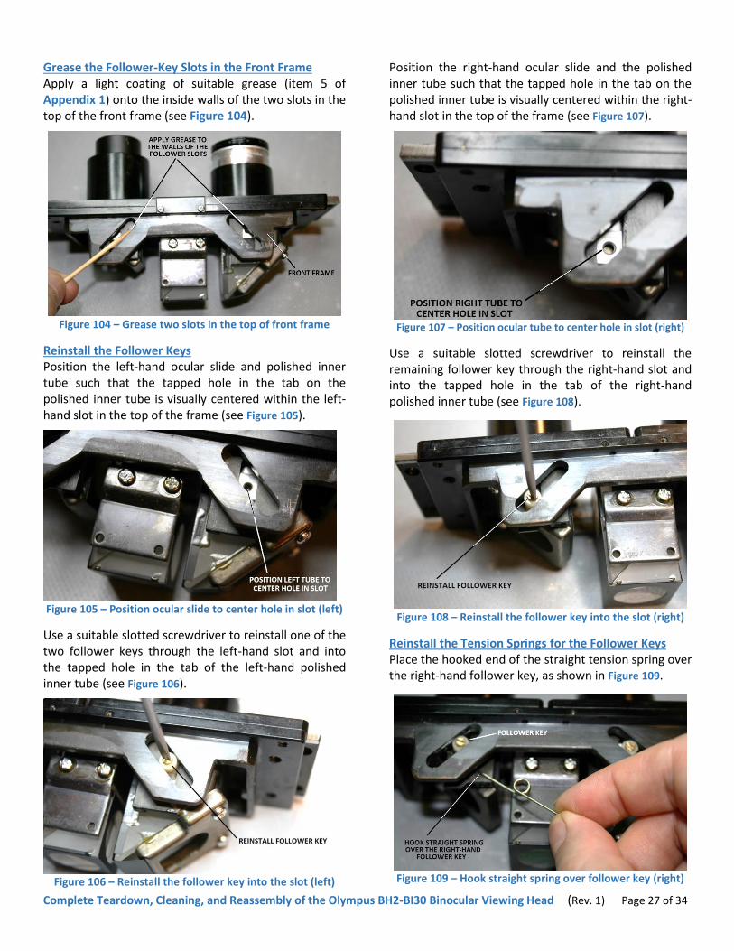
Grease the Follower-Key Slots in the Front Frame Apply a light coating of suitable grease (item 5 of Appendix 1) onto the inside walls of the two slots in the top of the front frame (see Figure 104).
Figure 104 – Grease two slots in the top of front frame
Reinstall the Follower Keys Position the left-hand ocular slide and polished inner tube such that the tapped hole in the tab on the polished inner tube is visually centered within the left-hand slot in the top of the frame (see Figure 105).
Figure 105 – Position ocular slide to center hole in slot (left)
Use a suitable slotted screwdriver to reinstall one of the two follower keys through the left-hand slot and into the tapped hole in the tab of the left-hand polished inner tube (see Figure 106).
Figure 106 – Reinstall the follower key into the slot (left)
Position the right-hand ocular slide and the polished inner tube such that the tapped hole in the tab on the polished inner tube is visually centered within the right-hand slot in the top of the frame (see Figure 107).
Figure 107 – Position ocular tube to center hole in slot (right)
Use a suitable slotted screwdriver to reinstall the remaining follower key through the right-hand slot and into the tapped hole in the tab of the right-hand polished inner tube (see Figure 108).
Figure 108 – Reinstall the follower key into the slot (right)
Reinstall the Tension Springs for the Follower Keys Place the hooked end of the straight tension spring over the right-hand follower key, as shown in Figure 109.
Figure 109 – Hook straight spring over follower key (right)

Complete Teardown, Cleaning, and Reassembly of the Olympus BH2-BI30 Binocular Viewing Head (Rev. 1) Page 28 of 34
Position the straight tension spring such that the coil in the spring aligns with the right-hand tapped hole in the spring-mounting bracket on the P3/P4 prism mount (see Figure 110).
Figure 110 – Align coil of straight spring with hole (right)
Use a suitable slotted screwdriver to reinstall the slotted retaining screw to secure the straight tension spring onto the spring-mounting bracket on the P3/P4 prism mount (see Figure 111).
Figure 111 – Secure the straight spring with screw (right)
Place the hooked end of the bent tension spring over the left-hand follower key, as shown in Figure 112.
Figure 112 – Hook bent spring over follower key (left)
Position the bent tension spring such that the coil in the spring aligns with the left-hand tapped hole in the spring-mounting bracket on the P3/P4 prism mount (see Figure 113).
Figure 113 – Align coil of bent spring with hole (left)
Use a suitable slotted screwdriver to reinstall the slotted retaining screw to secure the bent tension spring onto the spring-mounting bracket on the P3/P4 prism mount (see Figure 114).
Figure 114 – Secure the bent spring with screw (left)
Lift the tails of the two tensions springs and place them over the heads of the opposite retaining screws, thereby pre-loading the tension springs (see Figure 115).
Figure 115 – Pre-load the two tension springs
Complete Teardown, Cleaning, and Reassembly of the Olympus BH2-BI30 Binocular Viewing Head (Rev. 1) Page 29 of 34
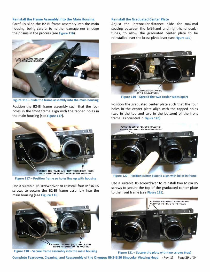
Reinstall the Frame Assembly into the Main Housing Carefully slide the B2-BI frame assembly into the main housing, being careful to neither damage nor smudge the prisms in the process (see Figure 116).
Figure 116 – Slide the frame assembly into the main housing
Position the B2-BI frame assembly such that the four holes in the front frame align with the tapped holes in the main housing (see Figure 117).
Figure 117 – Position frame so holes line up with housing
Use a suitable JIS screwdriver to reinstall four M3x6 JIS screws to secure the B2-BI frame assembly into the main housing (see Figure 118).
Figure 118 – Secure frame assembly into the main housing
Reinstall the Graduated Center Plate Adjust the interocular-distance slide for maximal spacing between the left-hand and right-hand ocular tubes, to allow the graduated center plate to be reinstalled over the brass pivot lever (see Figure 119).
Figure 119 – Spread the two ocular tubes apart
Position the graduated center plate such that the four holes in the center plate align with the tapped holes (two in the top and two in the bottom) of the front frame (as oriented in Figure 120).
Figure 120 – Position center plate to align with holes in frame
Use a suitable JIS screwdriver to reinstall two M2x4 JIS screws to secure the top of the graduated center plate to the front frame (see Figure 121).
Figure 121 – Secure the plate with two screws (top)

Complete Teardown, Cleaning, and Reassembly of the Olympus BH2-BI30 Binocular Viewing Head (Rev. 1) Page 30 of 34
Use a suitable JIS screwdriver to reinstall two M2x4 JIS screws to secure the bottom of the graduated center plate to the front frame (see Figure 122).
Figure 122 – Secure the plate with two screws (bottom)
Reinstall the Plastic Finger Grips Grasp the two ocular tubes and slide them to their maximum spacing such that the screw holes for the plastic finger grips are not obscured by the front frame (see Figure 123, left-hand side holes are shown).
Figure 123 – Set the ocular tubes to their maximum spacing
Place the left-hand finger grip into position over the left-hand ocular tube (see Figure 124).
Figure 124 – Place the finger grip into position (left)
Use a suitable JIS screwdriver to reinstall an M2x10 JIS screw into the front of the left-hand finger grip, to secure it to the left-hand ocular slide (see Figure 125).
Figure 125 – Reinstall front screw into the finger grip (left)
Use a suitable JIS screwdriver to reinstall two M2.6x5 JIS screws through the two holes in the left-hand ocular slide (from the back) to secure the left-hand finger grip to the ocular slide (see Figure 126).
Figure 126 – Reinstall back screws into the finger grip (left)
Place the right-hand finger grip into position over the right-hand ocular tube (see Figure 127).
Figure 127 – Place the finger grip into position (right)

Complete Teardown, Cleaning, and Reassembly of the Olympus BH2-BI30 Binocular Viewing Head (Rev. 1) Page 31 of 34
Use a suitable JIS screwdriver to reinstall an M2x10 JIS screw into the front of the right-hand plastic finger grip to secure it to the right-hand ocular slide (see Figure
128)
Figure 128 – Reinstall front screw into the finger grip (right)
Use a suitable JIS screwdriver to reinstall two M2.6x5 JIS screws through the two holes in the right-hand ocular slide (from the back) to secure the right-hand finger grip to the ocular slide (see Figure 129).
Figure 129 – Reinstall back screws into the finger grip (right)
If desired, you may skip the precise alignment procedure in the following section and proceed instead to the to the Reinstall the Helical Focus Ring (Left) – Less Accurate section of this document, which will allow you to install and adjust the zero-diopter point of the helical focus ring quicker and more simply, but with potentially less accurate results.
Reinstall the Helical Focus Ring (Left) – Most Accurate Place the helical focus ring onto the left-hand ocular tube (see Figure 130) and use a 1.3mm Allen wrench or driver to temporarily snug the three M2.6x4 set screws to temporarily secure the focus ring in position (see Figure 131).
Figure 130 – Place helical focus ring onto ocular tube (left)
Figure 131 – Tighten set screws to secure helical focus ring
Temporarily reinstall the BH2-BI30 binocular viewing head onto a suitable BH-2 microscope stand and place a single 10x ocular into the right-hand ocular tube. Set the microscope up to view a suitable specimen through this single ocular, and carefully focus on an easily-identified test feature of the specimen slide. Now take the 10x ocular out of the right-hand ocular tube and place it into the left-hand ocular tube. Using the same eye as before, once again view the specimen (with the ocular in the left-hand tube this time) and carefully adjust the helical focus ring on the left-hand ocular tube (but do not touch the coarse or fine focus knobs on the stand) to obtain a sharp focus on the test feature, similar to what was previously observed through the other ocular tube. Once the image has been optimally focused, the helical focus tube is adjusted to the zero-diopter point, although the zero-diopter marking on the focus ring will likely not be aligned with the white dot on the plastic finger grip. To correct this, use a 1.3mm Allen wrench or driver to carefully loosen the three M2.6x4 set screws securing the helical focus ring to the black helical tube, without turning the black helical tube in the process (see Figure 132).

Complete Teardown, Cleaning, and Reassembly of the Olympus BH2-BI30 Binocular Viewing Head (Rev. 1) Page 32 of 34
Figure 132 – Loosen set screws securing helical focus ring
Carefully position the now-loosened helical focus ring so that the zero-diopter marking on the focus ring aligns with the white dot on the plastic finger grip (see Figure 133).
Figure 133 – Align the zero-diopter marking with white dot
Next, use a 1.3mm Allen wrench or driver to tighten the three M2.6x4 set screws to secure the helical focus ring onto the black helical tube (see Figure 131), being careful to prevent the helical focus ring from rotating while the set screws are tightened.
If this procedure has been performed properly, the 10x ocular can be removed from the left-hand ocular tube (with the stand focused on the test feature of the specimen and with the helical focus ring set to zero) and placed into the right-hand ocular tube, and the view through the right-hand tube (using the same eye) should still be in correct focus. If this is not the case, repeat the above procedure until satisfactory results are obtained.
Reinstall the Helical Focus Ring (Left) – Less Accurate Carefully adjust the black helical tube on the left-hand ocular tube such that the top surface of the helical tube extends the same distance from the plastic finger grip as does the black fixed sleeve in the right-hand ocular tube (see Figure 134).
Figure 134 – Adjust helical focus tube for equal tube lengths
Place the helical focus ring onto the left-hand ocular tube, being careful to prevent the helical tube from rotating (see Figure 130), and align the zero-diopter marking on the helical focus ring with the white dot on the plastic finger grip (see Figure 133). Use a 1.3mm Allen wrench or driver to tighten the three M2.6x4 set screws to secure the helical focus ring into its final position on the black helical tube (see Figure 131).
Reinstall the Black Trim Ring for Ocular Tube (Right) Place three or four small spots of a suitable adhesive (item 8 of Appendix 1) equidistantly spaced around the inside edge of the right-hand ocular tube, as shown in Figure 135.
Figure 135 – Apply spots of adhesive to ocular tube (right)
Carefully place the black trim ring over the fixed sleeve protruding from the right-hand ocular tube and press it in place until it is properly seated in the adhesive (see Figure 136 and Figure 137). Carefully wipe away any adhesive squeeze-out.

Complete Teardown, Cleaning, and Reassembly of the Olympus BH2-BI30 Binocular Viewing Head (Rev. 1) Page 33 of 34
Figure 136 – Place trim ring over the ocular tube (right)
Figure 137 – Press trim ring into adhesive to seat it (right)
Ready for Service The newly reconditioned BH2-BI30 binocular viewing head is now ready to be put back into service.
Original Olympus Documentation A PDF version of the Olympus repair manual for the BH2-BI30 binocular viewing head was used as a reference during the preparation of this document (see Figure 138).
Figure 138 – The Olympus BH2-BI30 repair manual
In addition to the above-referenced BH2-BI30 binocular viewing head repair manual, a PDF of an early version of the Olympus BH2 (BHS) repair manual was also used (see Figure 139).
Figure 139 – The Olympus BH2 (BHS) repair manual
The PDF versions (scans of original hard copies) of both
of these useful Olympus resources are available for
download at various microscope-related hobbyist sites
on the internet, and can usually be located by searching
for the document title in an internet search engine,
such as Google or Bing.
How to Contact the Author Please feel free to direct any questions or comments regarding this document (or BH-2 microscopes in general) to the author, at the following email address:

Complete Teardown, Cleaning, and Reassembly of the Olympus BH2-BI30 Binocular Viewing Head (Rev. 1) Page 34 of 34
Appendix 1
Sources for Replacement Tools and Supplies Referenced in this Document
Table 1 and Table 2 list specific information for the various tools, and supplies discussed in this document. These tables list only the items that may be difficult to source locally. The pricing and availability listed below is accurate as-of September 2017, but is subject to change without notice.
Item Description Manufacturer Manufacturer Model / # Vendor Vendor # Price
1 1.3mm Allen Driver Wiha 26313 Amazon --- $6.28
2 Heat gun, electric, 1500W Harbor Freight Drill Master Harbor Freight 96289 $12.99
3 Screwdriver set, JIS, 4 pieces Hozan JIS-4 Amazon --- $19.66
4 Tweezers, precision, set of 7 Oulii --- Amazon --- %9.99
Table 1 – Tools referenced in this document
Item Description Manufacturer Manufacturer Model / # Vendor Vendor # Price
5 Molykote® 44 Light grease5, 28g Dow Corning Molykote® 44 Light Amazon --- $6.95
6 HELIMAX-XPTM grease for helicoid focus mechanism, with PTFE, 1oz
µMicroLubrol HELIMAX-XPTM Amazon --- $6.95
7 Lens cleaning wipes, pre-moistened,
6x5 inches, 100 count Zeiss Zeiss Amazon --- $8.79
8 Silicone gasket RTV, black, 3oz J-B Weld® J-B Weld® 32329 Amazon --- $5.84
Table 2 – Supplies referenced in this document
Table 3 lists the contact information for the vendors referenced in Table 1 and Table 2.
Vendor URL Local Phone Toll Free Fax email
Amazon www.amazon.com --- --- --- ---
Harbor Freight www.harborfreight.com --- 1-800-423-2567 --- ---
Table 3 – Vendor Listing
5 Molykote® 44 is available in two weights (Molykote® 44 Light and Molykote® 44 Medium). Be sure to get Molykote® 44 Light, as the
Molykote® 44 Medium is too heavy for this application.