Embed Size (px)
Citation preview
Mea
sure
men
t tec
hnol
ogy
- Mad
e in
Ger
man
y
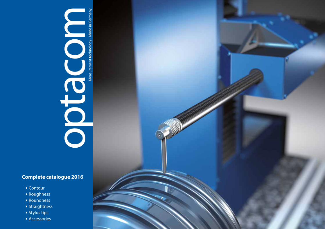
Complete catalogue 2016
4Contour4Roughness4Roundness4Straightness4Stylus tips4Accessories

2 optacom youtube-channel
New products and training videos can be seen at our youtube-channel http://www.youtube.com/user/optacom1.

3Table of contents
optacom youtube-channel 2
Table of Contents 3
optacom measurement technology 4
The advantages of optacom measuring systems 5
optacom product overview 6
optacom LC-10 8
optacom VC-series 10
optacom VC-serie overview 12
optacom VC-10-UL-RDY 14
optacom VC-10-UL-RDSY 16
optacom VC-10-AIR 18
optacom VC-10 thread editon 20
optacom VC-10 tailstock edition 21
optacom zeropoint clamping system 22
optacom thread equipment 24
optacom tailstock 26
optacom thread equipment - spare parts 28
optacom Y-tables 30
optacom rotary-swivel table RSY 240-25 31
optacom automatic 4-way swival table 32
optacom centric clamping vise 33
optacom topdown 34
optacom vises 35
optacom vises 36
optacom stylus tip icons 37
optacom icon explanation 38
optacom stylus tip – coating and time of delivery 39
optacom stylus tips - standard 40
optacom stylus tips - standard conical 43
optacom conical - stylus tips 44
optacom roughness - stylus tips 45
optacom double stylus tips conical 46
optacom double stylus tips 47
optacom disc stylus systems 48
optacom quick-release fastener and miniature stylus arms 50
optacom cross and diamond stylus arms 51
special and ceramic stylus tip 52
optacom stylus pins 53
optacom trapezoidal thread stylus tips 54
optacom thread stylus tips 55
thread sensing arms, thread receptive and quick release fasteners 56
optacom special stylus tips 57
Mahr-compatible stylus tips - standard 58
Mahr-compatible stylus tips - conical 59
Hommel-compatible stylus tips 60
Taylor Hobson-compatible stylus tips 61
Mitutoyo-compatible stylus tips 62
Zeiss-compatible stylus tips - standard 64
Zeiss-compatible stylus tips - conical 65
optacom contour 66
optacom topdown 38
optacom contour - topdown evaluation with tolerances 68
optacom contour - topdown evaluation with roughness 70
optacom contour - topdown evaluation complete 71
optacom rough - roughness in its best shape 72
optacom rough - Parameter overview 73
optacom round 74
optacom round - the extension module for roundness measurements 75
optacom thread software 76
optacom - The best at last 82
Distributors worldwide 83

4 Enjoy the pleasant feeling of doing everything right from the beginning
Your investment in optacom is protected for years to come thanks to:
4Lifetime free software updates
4 Modular expansion of our machines
4 Subsequent expansion via options
4 Certi�cation according to DIN EN ISO 9001:2008
Made in Germany
optacom develops, manufactures and distributes world-class surface measurement systems since its founding in 1999. These measurement systems allow evaluation of contour, roughness, and roundness in a single pass. A foolproof, fully automatic and extremely rapid calibration as well as an equally rapid, uncom-plicated stylus tip replacement constitute the hallmarks of ca-refully crafted precision systems.
Thanks to a broad range of special tracing arms and machine options, e. g. the newly developed rotary-swivel table, even composite or other complicated measuring tasks on complex parts become almost child‘s play. Our products have con-vinced numerous manufacturing and measurement laborato-ries worldwide of the quality, robustness and e�ciency of our measurement systems.
optacom‘s young and enthusiastic team takes care of all custo-mer concerns. The emphasized partnership with the customer ensures the rapid realization of individual needs and special measurement requirements. Anyone who has ever worked with an optacom system is reluctant to change. “Follow-up or-ders are fortunately very common in our daily business. And also the friendly con�rmation of our customers that shows we are on the right track with our concept,” says founder and CEO Diana Erhard. Now, let us show you and win you over.
Innovations made by optacom
5
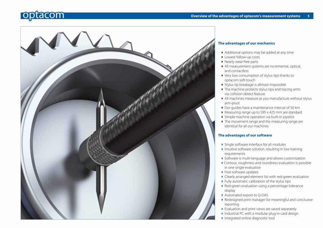
The advantages of our mechanics
4 Additional options may be added at any time4 Lowest follow-up costs4 Nearly wear-free parts4 All measurement systems are incremental, optical, and contactless4 Very low consumption of stylus tips thanks to optacom soft-touch 4 Stylus tip breakage is allmost impossible4 The machine protects stylus tips and tracing arms via collision-detect feature4 All machines measure as you manufacture without stylus arm-pivot4 Our guides have a maintenance interval of 50 km4 Measuring range up to 595 x 425 mm are standard4 Simple machine operation via built-in joystick4 The movement range and the measuring range are identical for all our machines
The advantages of our software
4 Single software interface for all modules 4 Intuitive software solution, resulting in low training requirements 4 Software is multi-language and allows customization 4Contour, roughness and roundness evaluation is possible in one single evaluation 4 Free software updates 4 Clearly arranged element list with red-green evaluation 4 Fully automatic calibration of the stylus tips 4 Red-green evaluation using a percentage tolerance display 4 Automated export to Q-DAS 4Redesigned print manager for meaningful and conclusive reporting 4 Evaluation and print views are saved separately 4 Industrial PC with a modular plug-in card design 4 Integrated online diagnostic tool
Overview of the advantages of optacom‘s measurement systems

optacom product overview
LC-10 VC-10 VC-10-EL VC-10-UL
Resolution in X and Z axis 0.02 µm / 0.79 µin 0.002 µm / 0.079 µin 0.002 µm / 0.079 µin 0.002 µm / 0.079 µin
Measuring range (X axis) 225 mm / 8.86 inch 225 mm | 8.86 inch 325 mm / 12.80 inch 425 mm / 16.73 inch
Measuring range (Z axis) 225 mm / 8.86 inch 225 mm | 8.86 inch 325 mm / 12.80 inch 425 mm / 16.73 inch
Straightness (1.5 + L/100) µm (0.5 + L/100) µm (0.5 + L/100) µm (0.5 + L/100) µm
L in mm / in (59 + L x 10) µin (20 + L x 10) µin (20 + L x 10) µin (20 + L x 10) µin
Accuracy +/- (1.5 + L/100) µm +/- (0.5 + L/100) µm +/- (0.5 + L/100) µm +/- (0.5 + L/100) µm
L in mm / in +/- (59 + L x 10) µin +/- (20 + L x 10) µin +/- (20 + L x 10) µin +/- (20 + L x 10) µin
Contour ✔ ✔ ✔ ✔
roughness ¢ ¢ ¢ ¢
Y-table YTA-25 / YTM-25 ¢ ¢ ¢ ¢
Y-table YTA-100 ¢ ¢ ¢ ¢
RSY 240-25 £ £ ¢ ¢
topdown ¢ ¢ ¢ ¢
Basis with zeropoint clamping ¢ ¢ ¢ ¢
Quick exchange basis for basis with zeropoint clamping ¢ ¢ ¢ ¢
Basis without zeropoint campling incl. quick exchange basis ¢ ¢ ¢ ¢
Tailstock £ £ ¢ ¢
¢ optionally available
6
Basis without zeropoint campling incl. quick exchange basis

optacom productoverview
VC-10-XXL VC-10-UL-RDY VC-10-UL-RDSY VC-10-AIR
Resolution in X and Z axis 0.002 µm / 0.079 µin 0.002 µm / 0.079 µin 0.002 µm / 0.079 µin 0.002 µm / 0.079 µin
Measuring range (X axis) 595 mm / 23.43 inch 425 mm | 16.73 inch 425 mm / 16.73 inch 300 mm / 11.81 inch
Measuring range (Z axis) 425 mm / 16.73 inch 530 mm / 20.86 inch 530 mm / 20.86 inch 325 / 425 mm / 12.8 / 16.73 inch
Straightness (2.0 + L/100) µm (0.5 + L/100) µm (0.5 + L/100) µm (0.25 + L/1000) µm
L in mm / in (79 + L x 10) µin (20 + L x 10) µin (20 + L x 10) µin (10 + L) µin
Accuracy +/- (2.0 + L/100) µm +/- (0.5 + L/100) µm +/- (0.5 + L/100) µm +/- (0.5 + L/200) µm
L in mm / in +/- (79 + L x 10) µin +/- (20 + L x 10) µin +/- (20 + L x 10) µin +/- (20 + L x 5) µin
Contour ✔ ✔ ✔ ✔
Roughness £ ¢ ¢ ¢
Y-table YTA-25 / YTM-25 ¢ ¢ ¢ ¢
Y-table YTA-100 ¢ ¢ ¢ ¢
RSY 240-25 £ ¢ ¢ ¢
topdown ¢ ¢ ¢ ¢
Basis with zeropoint clamping ¢ £ £ £
Quick exchange basis for basis with zeropoint clamping ¢ £ £ £
Basis without zeropoint campling incl. quick exchange basis ¢ £ £ £
Tailstock ¢ £ £ £
¢ optionally available
7

8
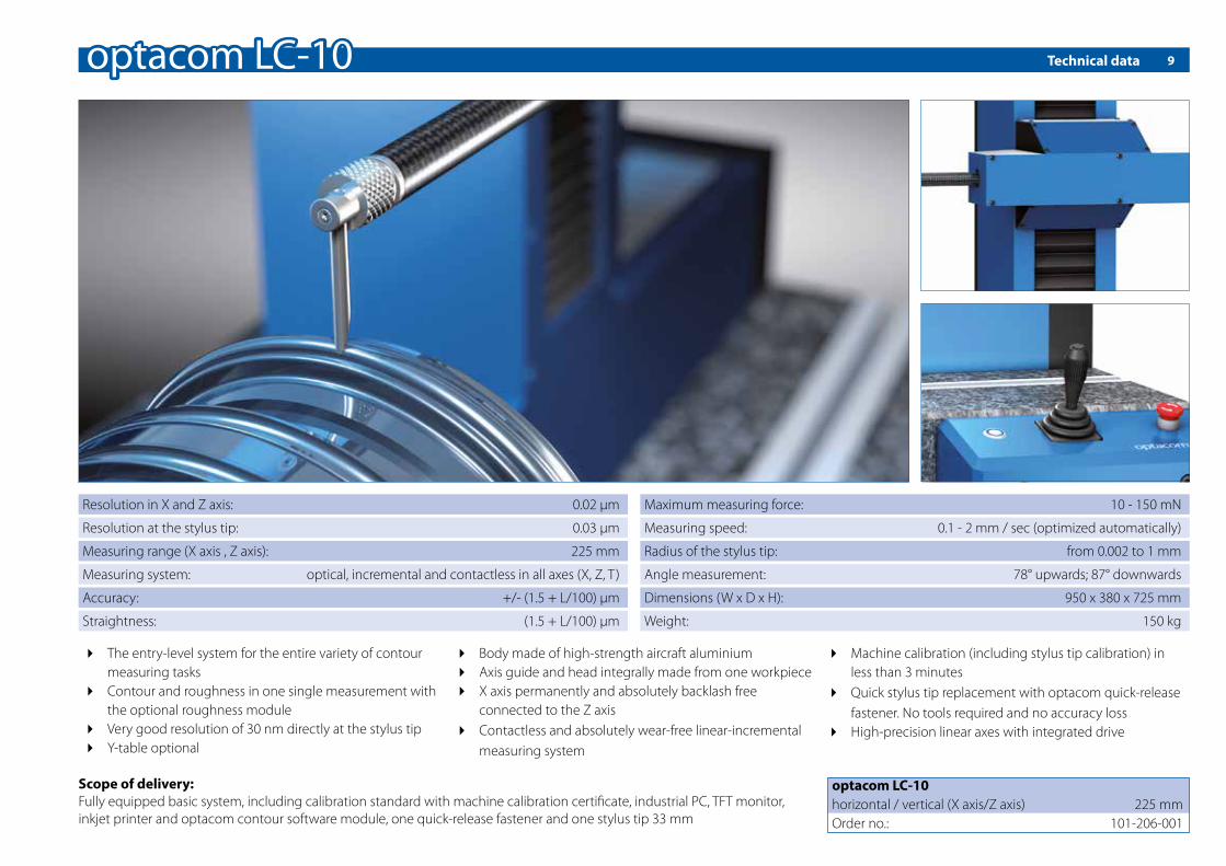
The optacom LC-10 represents the perfect entry model. Espe-cially in cases where the entire scope of service of a modern universal measuring machine is needed, the optacom LC-10 is compared to the high precision of a VC-10 – the most suitable product.It covers the measuring range and features the technical re-�nements of our all-round machine VC-10, thus provides an
outstanding measuring accuracy. Therefore the LC-10 com-bines in a single housing a perfect measurement quality and an attractive price.The LC-10 is a real optacom measuring machine in every detail. It uses a high-precision linear axis with an integrated drive and wear-free, linear incremental system.
It´s body is made of high-strength aircraft aluminium. The ope-ration and the software modules used are identical to those found in other optacom measuring machines.
However the LC-10 cannot be extended to a universal measu-ring machine with the optional rotary-swivel table.
Simply a�ordable - the perfect introduction to contour measurement technology
9Technical data
4 The entry-level system for the entire variety of contour measuring tasks4 Contour and roughness in one single measurement with the optional roughness module4 Very good resolution of 30 nm directly at the stylus tip4 Y-table optional
4 Body made of high-strength aircraft aluminium4 Axis guide and head integrally made from one workpiece4 X axis permanently and absolutely backlash free connected to the Z axis4 Contactless and absolutely wear-free linear-incremental measuring system
4Machine calibration (including stylus tip calibration) in less than 3 minutes4 Quick stylus tip replacement with optacom quick-release fastener. No tools required and no accuracy loss4 High-precision linear axes with integrated drive
Resolution in X and Z axis: 0.02 μm
Resolution at the stylus tip: 0.03 μm
Measuring range (X axis , Z axis): 225 mm
Measuring system: optical, incremental and contactless in all axes (X, Z, T)
Accuracy: +/- (1.5 + L/100) μm
Straightness: (1.5 + L/100) µm
Scope of delivery:Fully equipped basic system, including calibration standard with machine calibration certi�cate, industrial PC, TFT monitor, inkjet printer and optacom contour software module, one quick-release fastener and one stylus tip 33 mm
optacom LC-10horizontal / vertical (X axis/Z axis) 225 mmOrder no.: 101-206-001
Maximum measuring force: 10 - 150 mN
Measuring speed: 0.1 - 2 mm / sec (optimized automatically)
Radius of the stylus tip: from 0.002 to 1 mm
Angle measurement: 78° upwards; 87° downwards
Dimensions (W x D x H): 950 x 380 x 725 mm
Weight: 150 kg

10 The measure of all things - our multitalents for high precision measurement
Are you looking for an all-round system to control the whole variety of contour measurement tasks with outstanding accu-racy? If so, the optacom VC-10 may be the right solution for you. It performs contour measurements alone or in combina-tion with roughness simultaneously as well as roundness mea-surements or composite measurements (e. g., with the new rotary-swivel table).
Even complicated measurement tasks of complex formed ob-jects will be easy to handle. The VC-10-EL/-UL was speci�cally designed for extension with our rotary-swivel table.Through the extension of the measuring range in X and Z axis up to 370 mm, we can fully leverage the possibilities of the rotary-swivel table.
Therefore the VC-10 is a convincing value proposition because of its ease-to-use nature and outstanding precision.At the stylus tip it reaches a genuine - not just simply calculated - resolution of 3 nm over the entire measuring range.

11Technical data
4 The powerful all-round system for the entire variety of contour measurement tasks4 Contour and roughness in one measurement with the optional roughness module4 Roundness measurements and composite measurements with optional rotary-swivel table 4Outstanding genuine resolution of 3 nm direct at the stylus tip4 Y-table optional
4 Axis guide and head integrally made from one workpiece4 X axis permanently and absolutely backlash free connected to the Z axis4 High-precision linear axes with integrated drive4 Body made of high-strength aircraft aluminium4 Contactless and absolutely wear-free linear-incremental measuring system
4Machine calibration (including stylus tip calibration) in less than 3 minutes4 Quick stylus tip replacement with optacom quick-release fastener. No tools required and no accuracy loss4 Fully equipped basic system, including calibration standard, industrial PC with TFT monitor, printer and optacom contour software module
Delivery scope:Measuring machine optacom VC-10, industrial PC with TFT monitor, mouse and keyboard, inkjet printer, Windows operating system, optacom contour software, calibration standard with certi-�cate (for machine calibration purposes), two quick-release fasteners and two stylus tips
Resolution in X and Z axis: 0.002 μm
Resolution at stylus tip: 0.003 µm
Measurement system: optical incremental and contactless in all axis (X, Z, T)
Accuracy: +/- (0.5 + L/100) µm
Straightness: (0.5 + L/100) µm
Maximum measuring force: 10 - 150 mN
Measuring speed: 0.1 – 2 mm/sec (optimized automatically)
Radius of the stylus tip: 0.002 – 1 mm
Measurable gradients: 78° upwards; 87° downwards
Weight VC-10: 150 kg
Weight VC-10-EL: 180 kg
Weight VC-10-UL: 200 kg
Weight VC-10-XXL: 325 kg
A certi�ed calibration standard is supplied with the machine
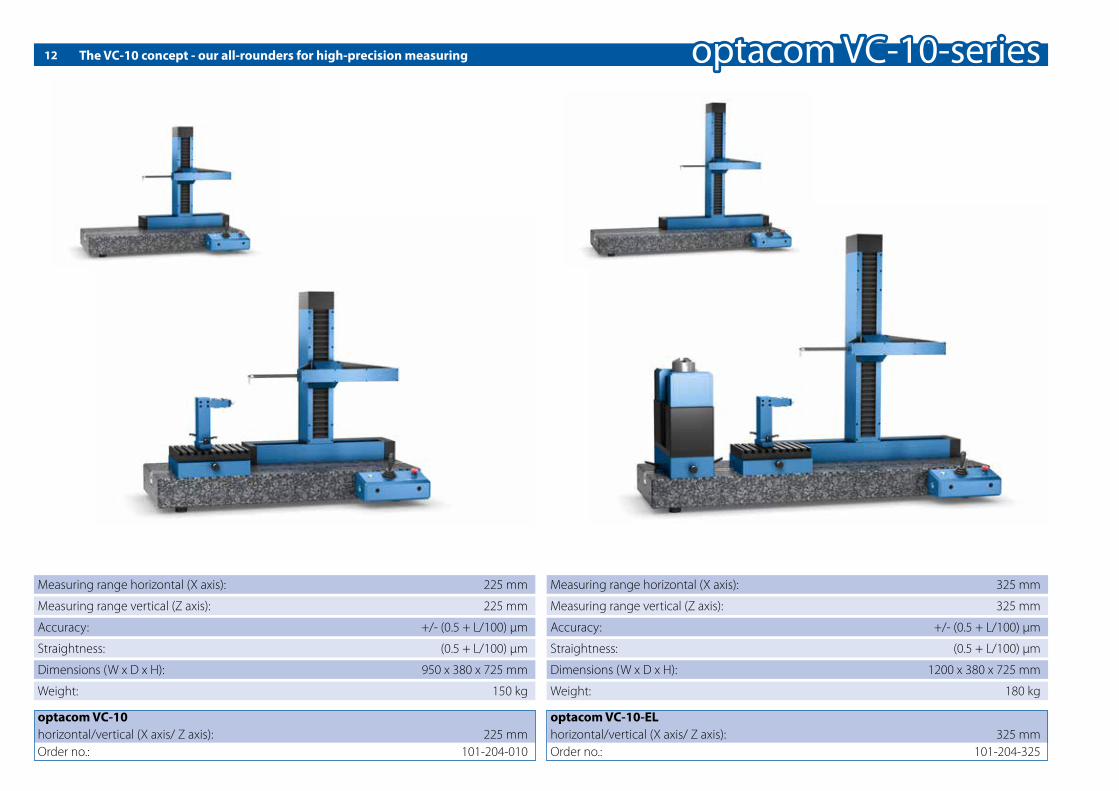
12 The VC-10 concept - our all-rounders for high-precision measuring
VC-10The measure of all things…
VC-10-ELLet’s go round…
optacom VC-10horizontal/vertical (X axis/ Z axis): 225 mmOrder no.: 101-204-010
Measuring range horizontal (X axis): 225 mm
Measuring range vertical (Z axis): 225 mm
Accuracy: +/- (0.5 + L/100) µm
Straightness: (0.5 + L/100) µm
Dimensions (W x D x H): 950 x 380 x 725 mm
Weight: 150 kg
optacom VC-10-ELhorizontal/vertical (X axis/ Z axis): 325 mmOrder no.: 101-204-325
Measuring range horizontal (X axis): 325 mm
Measuring range vertical (Z axis): 325 mm
Accuracy: +/- (0.5 + L/100) µm
Straightness: (0.5 + L/100) µm
Dimensions (W x D x H): 1200 x 380 x 725 mm
Weight: 180 kg

13Technical data
VC-10-ULSize matters…
VC-10-XXLProbably the longest measuring machine in the world…
optacom VC-10-ULhorizontal/vertical (X axis/ Z axis): 425 mmOrder no.: 101-204-425
Measuring range horizontal (X axis): 425 mm
Measuring range vertical (Z axis): 425 mm
Accuracy: +/- (0.5 + L/100) µm
Straightness: (0.5 + L/100) µm
Dimensions (W x D x H): 1200 x 380 x 725 mm
Weight: 200 kg
optacom VC-10-XXLhorizontal/vertical (X axis/ Z axis): 595/425 mmOrder no.: 101-204-595
Measuring range horizontal (X axis): 595 mm
Measuring range vertical (Z axis): 425 mm
Accuracy: +/- (2 + L/100) µm
Straightness: (2 + L/100) µm
Dimensions (W x D x H): 1450 x 450 x 1050 mm
Weight: 325 kg

6 sells ...14
Are you looking for a universal measuring station that not only replaces your contour, roughness and roundness, but also your gear measuring machine?
Then you will de�nitely like our optacom VC-10-UL-RDY. Con-sisting of 6 measuring axes it does contour measurements au-tomatically or in combination with a simultaneous roughness measurement in a perfect manner.
Next to these qualities, it does roundness measurements or composed measurements with an integrated swivel table, which is placed on an installed rotary axis. This leads to the fact that even complicated measuring tasks of complexly formed objects become very easy.
At the stylus tip it reaches a true, not only simply calculated resolution of less than 3 nm and can do this over the entire measuring range.

15
4 The most powerful all-round system for the entire variety of contour measuring tasks4 Contour and roughness in one measurement with the integrated roughness module4 Roundness measurements and gear measurements with the integrated rotary table
4 Y-table with 530 mm travel4 Rotary axis with a rotation angle of 210°4 High-precision linear axis with an integrated drive4 Contact-free, linear incremental measuring systems, absolutely wear free4 Various chucks available
4Machine calibration (including stylus tips calibration) in less than 3 minutes4 Rapid stylus tips change with optacom quick-release fastener4 Body made of high-strength aircraft aluminium
Delivery scope: Measuring machine optacom VC-10-UL-RDY, industrial PC with TFT monitor, mouse and keyboard, inkjet printer, Windows operating system, optacom Suite 2 complete software, calibration standard with certi�cate (for machine calibration purposes), two quick-release fasteners and two stylus tips
Technical data
Resolution in X and Z axis: 0.002 µm
Resolution at stylus tip: 0.003 µm
Measurement system: optical incremental and contactless (X, Z, T, R, D, Y)
Accuracy: +/- (0.5 + L/100) µm
Straightness: (0.5 + L/100) µm
Dimensions (W x D x H): 1065 x 1060 x 980 mm
Measuring speed: 0.1 – 2 mm/sek (optimized automatically)
Measurable gradients: 78° upwards; 87° downwards
Maximum measuring force: 10 - 150 mN
Measuring range (X + Z axis): 425 mm
Measuring range (Y axis): 530 mm
Rotation angle (D): 210°
Weight (about): 275 kg
optacom VC-10-UL-RDYhorizontal/vertical (X axis/Z axis) / Y axis 425 mm / 530 mmOrder no.: 101-227-425
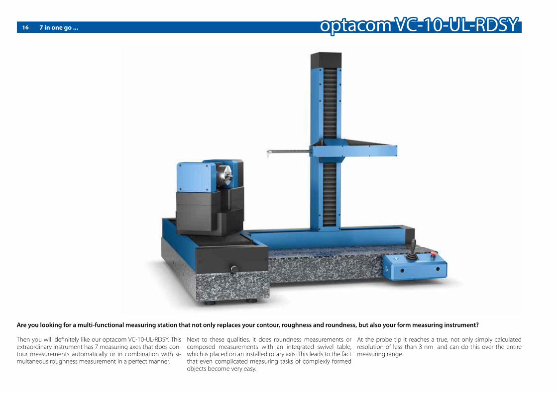
7 in one go ...
Are you looking for a multi-functional measuring station that not only replaces your contour, roughness and roundness, but also your form measuring instrument?
Then you will de�nitely like our optacom VC-10-UL-RDSY. This extraordinary instrument has 7 measuring axes that does con-tour measurements automatically or in combination with si-multaneous roughness measurement in a perfect manner.
Next to these qualities, it does roundness measurements or composed measurements with an integrated swivel table, which is placed on an installed rotary axis. This leads to the fact that even complicated measuring tasks of complexly formed objects become very easy.
At the probe tip it reaches a true, not only simply calculated resolution of less than 3 nm and can do this over the entire measuring range.
16

Technical data
4 The most powerful all-round system for the entire variety of contour measuring tasks4 Contour and roughness in one measurement with the integrated roughness module4 Roundness measurements and consolidated measu- rements with the integrated swiveling table
4 Y-table with 530 mm travel4 Rotary axis with a rotation angle of 210°4 Swivel axis with an angle of 240°4 High-precision linear axis with an integrated drive4 Body made out of high-strength aircraft aluminium
4 Contact-free, linear incremental measuring systems, absolutely wear free4Machine calibration (including unilaterally stylus tips calibration) in less than 3 minutes4 Rapid stylus tips change with optacom quick-release fastener
Delivery scope: Measuring machine optacom VC-10-UL-RDSY, industrial PC with TFT monitor, mouse and keyboard, inkjet printer, Windows operating system, optacom Suite 2 complete software, calibration standard with certi�cate (for machine calibration purposes), two quick-release fasteners and two stylus tips
Resolution in X and Z axis: 0.002 µm
Resolution at stylus tip: 0.003 µm
Measurement system: optical incremental and contactless (X, Z, T, R, S, D, Y)
Accuracy: +/- (0.5 + L/100) µm
Straightness: (0.5 + L/100) µm
Dimensions (W x D x H): 1065 x 1060 x 980 mm
Measuring speed: 0.1 – 2 mm/sek (optimized automatically)
Measurable gradients: 78° upwards; 87° downwards
Measuring range (X + Z axis): 425 mm
Measuring range (Y axis): 530 mm
Rotation angle (D): 210°
Swivel angle (S): 240°
Weight (about): 275 kg
optacom VC-10-UL-RDSYhorizontal/vertical (X axis/Z axis) / Y axis 425 mm / 530 mmOrder no.: 101-228-425
17

18
Absolutely revolution “AIR “- constant accuracy
The new
VC-10-AIRSimple and precise measuring with air!
Accuracy: +/- (0.5 + L/200) µm
Straightness: (0.25 + L/1000) µm
Measuring range vertical:
325 / 425 mm
Measuring range horizontal:
300 mm
Absolutely revolution“AIR“
Absolutely revolution “AIR “- never ending accuracy

19Technical data
Absolutely revolution „AIR“
You have been looking for a high-end system with outstan-ding precision which covers the whole spectrum of contour measuring? Then our newly developed optacom VC-10-AIR will �t your concept perfectly. Thanks to its innovative air guide in the X axis combined with a lateral force free gear, impossible measurements are now do-able.
It completes contour measurements alone or in combination with simultaneously roughness, straightness or combined measurements.That way even complicated measurement tasks at complex formed objects become a childproof practice.The VC-10- AIR was especially designed for straightness and roughness measurements.
Even complicated measuring tasks on complex formed ob-jects become a piece of cake. The AIR was especially designed to measure straightness and roundness.Because of its very high measuring range in the X and Z axis ( 300 /max. 425 mm), even very large measuring tasks can be executed with unheard precision.The AIR will not only convince you thru its easy handling but furthermore because of the wear free air bearing in the X axis.
Resolution in X and Z axis: 0.002 µm
Resolution at stylus tip: 0.003 µm
Measuring range horizontal (X axis): 300 mm
Measuring range vertical (Z axis): 325 mm / 425 mm
Measurement system: optical incremental and contactless in all axes (X, Z, T)
Accuracy: +/- (0.5 + L/200) µm
Straightness: (0.25 + L/1000) µm
Maximum measuring force: 10 - 150 mN
Measuring speed: 0.1 – 2 mm/sec (optimized automatically)
Radius of the stylus tip: 0.002 – 1 mm
Measurable gradients: 78° upwards; 87° downwards
Weight (ca.): 350 kg
A certi�ed calibration standard is supplied with the machine
Scope of delivery:Measuring machine optacom VC-10-AIR, industrial PC, TFT monitor, mouse and keyboard, inkjet printer, Windows operating system, optacom contour software, calibration standard with ma-chine calibration certi�cate , two quick-release fastener and two stylus tips
optacom VC-10-EL-AIRhorizontal/vertical (X axis/Z axis) 300 mm / 325 mmOrder Number: 101-500-325
optacom VC-10-UL-AIRhorizontal/vertical (X axis/Z axis) 300 mm / 425 mmOrder Number: 101-500-425

The VC-10 thread edition20
Are you looking for a test assembly for quick and easy measurement of smooth and threaded ring gauges from M1 to M120?
The VC-10 thread edition features all options required for re-liable measurement in modern production environment: An integrated quick-exchange system and three receptacle plates allow adaptation to di�erent diameters in no time.
As the exchange precision amounts to less than 0.01 mm, se-lection of a di�erent diameter does not involve supplementa-ry procedures for orientation and calibration. It is su�cient to mount the required receptacle plate, to clamp the ring gauge and to start the program.
The entire measuring sequence is performed by the optacom software automatically, together with a particular program and the integrated motorized Y table.
VC-10 thread edition
Order no.: 101-207-225
Scope of delivery: VC-10, YTA, quick exchange basis, basis with zero tension, stud bolt set, set of threaded t nut set, set of threaded receptacle plates (M1 – M120), top down module, incl. thread software ‘Professional’. Stylus tips not included.
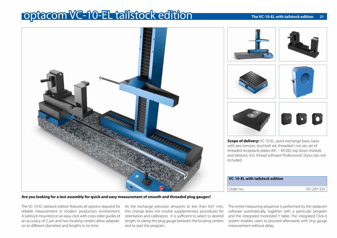
The VC-10-EL with tailstock edition 21
VC-10-EL with tailstock edition
Order no.: 101-207-325
Scope of delivery: VC-10-EL, quick exchange basis, basis with zero tension, stud bolt set, threaded t nut set, set of threaded receptacle plates (M1 – M120), top down module and tailstock, incl. thread software ‘Professional’. Stylus tips not included.
Are you looking for a test assembly for quick and easy measurement of smooth and threaded plug gauges?
The VC-10-EL tailstock edition features all options required for reliable measurement in modern production environment: A tailstock mounted on an easy-click with cross roller guides of an accuracy of 2 µm and two locating centers allow adaptati-on to di�erent diameters and lengths in no time.
As the exchange precision amounts to less than 0.01 mm, this change does not involve supplementary procedures for orientation and calibration. It is su�cient to select to desired length, to clamp the plug gauge between the locating centers and to start the program.
The entire measuring sequence is performed by the optacom software automatically, together with a particular program and the integrated motorized Y table. The integrated Click-it system enables users to proceed afterwards with ring gauge measurement without delay.

Click it ...
optacom Quick Exchange System for Zero Point
Are you looking for a method of speeding up your measurement at maximum repeatability?The quick exchange system for zero point re-presents an extremely sophisticated solution for this challenge: On the one hand, the ex-change precision amounts to less than 0.01 mm at highest repeatability, on the other hand the whole exchange procedure even does not take 10 seconds.
This way, interruptions of the measuring se-quence itself become negligible. Tension is generated by simple pressing in. Tension force amounts to 5.000, retention force to 10.000 N.
Clamping force: 5.000 N
Holding force: 10.000 N
Snap in force: 80 N
Pressure to release: 3 - 8 bar
Repeat accuracy: < 0,01 mm
Clamping time: < 0.1 s
Time to release: ca. 0.1 s
Maintenance interval / cycle: 250.000
22

Accessoires 23
Zeropoint clamping topdown StandardIncl. Zero and Compensation Nipple
Zeropoint clamping Centric Clamping ViseIncl. Zero and Compensation Nipple
Zeropoint clamping T Slot PlateIncl. Zero and Compensation Nipple
Zeropoint clamping topdown Standard
Order no.: 101-202-107
Zeropoint clamping Centric Clamping Vise
Order no.: 101-202-105
Zeropoint clamping T Slot Plate
Order no.: 101-202-108
Zero NippleClamping nipple “Easy Click” with Zero Point
Zero Nipple
Order no.: 101-208-006
Zeropoint clamping Standard Clamping Vise A25Incl. Zero and Compensation Nipple
Zeropoint clamping Standard Clamping Vise A25
Order no.: 101-202-106
Compensation NipplesClamping nipple “Easy Click” with compensation
Compensation Nipples
Order no.: 101-208-007
Automatic Y table YTA-25Y-movement range: 25 mm
Automatic Y table YTA-25
Order no.: 101-204-007
topdown Module for Quick Exchange Basis
topdown Module for Quick Exchange Basis
Order no.: 101-207-008
Centric Clamping Vise
Centric Clamping Vise
Order no.: 101-202-100
Standard Clamping Vise A-25
Standard Clamping Vise A-25
Order no.: 101-202-020

1
2
3
4
5
6
Measure threads ...
Are you looking for convenient measurement equipment for smooth and threaded ring gauges from M1 to M120? An integrated quick-exchange system and three receptacle plates allow adaptation to di�erent diameters in no time. As the exchange precision amounts to less than 0.01 mm, selec-tion of a di�erent diameter does not involve supplementary procedures for orientation and calibration. It is su�cient to mount the required receptacle plate, to clamp the ring gauge and to start the program.
The entire measuring sequence is performed by the optacom software automatically, together with a particular program and the integrated motorized Y table.The zero point quick exchange system is released by air pressu-re of 6 bar within 0.1 s. Tension is generated by simple pressing in. Tension force amounts to 5.000, retention force to 10.000 N.
Thread Software Professionalavailable only combined with optacom thread testing equipment
Order no.: 101-006-PRO
Thread Software Lightavailable only combined with optacom contour measuring machine
Order no.: 101-006-LIG
Thread Software Standardavailable only combined with optacom contour measuring machine
Order no.: 101-006-STA
1
2
3
4
5
6
Quick Exchange Basis Order no.: 101-207-012
Basis with Zeropoint clamping Order no.: 101-207-011
Automatic Y-Table Order no.: 101-204-007
Threaded Receptacle Plate Set M1-M120 Order no.: 101-207-013
Threaded T-Nut Set Order no.: 101-207-005
Stud Bolt Set Order no.: 101-207-002
24
Accessoires 25
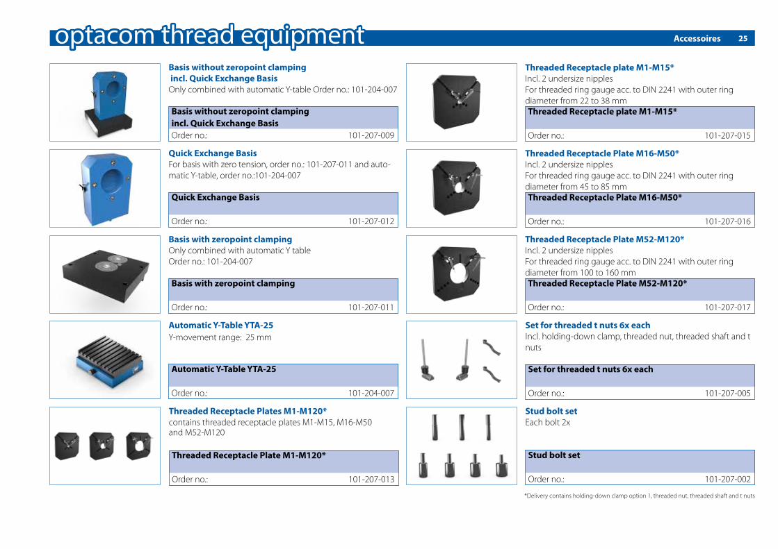
Basis without zeropoint clamping incl. Quick Exchange BasisOnly combined with automatic Y-table Order no.: 101-204-007
Threaded Receptacle plate M1-M15*Incl. 2 undersize nipplesFor threaded ring gauge acc. to DIN 2241 with outer ring diameter from 22 to 38 mm
Threaded Receptacle Plate M16-M50*Incl. 2 undersize nipplesFor threaded ring gauge acc. to DIN 2241 with outer ring diameter from 45 to 85 mm
Threaded Receptacle Plate M52-M120*Incl. 2 undersize nipplesFor threaded ring gauge acc. to DIN 2241 with outer ring diameter from 100 to 160 mm
Basis without zeropoint clamping incl. Quick Exchange BasisOrder no.: 101-207-009
Threaded Receptacle plate M1-M15*
Order no.: 101-207-015
Threaded Receptacle Plate M16-M50*
Order no.: 101-207-016
Threaded Receptacle Plate M52-M120*
Order no.: 101-207-017
Quick Exchange BasisFor basis with zero tension, order no.: 101-207-011 and auto-matic Y-table, order no.:101-204-007
Quick Exchange Basis
Order no.: 101-207-012
Basis with zeropoint clampingOnly combined with automatic Y tableOrder no.: 101-204-007
Basis with zeropoint clamping
Order no.: 101-207-011
Automatic Y-Table YTA-25Y-movement range: 25 mm
Automatic Y-Table YTA-25
Order no.: 101-204-007
Threaded Receptacle Plates M1-M120*contains threaded receptacle plates M1-M15, M16-M50 and M52-M120
Threaded Receptacle Plate M1-M120*
Order no.: 101-207-013
*Delivery contains holding-down clamp option 1, threaded nut, threaded shaft and t nuts
Set for threaded t nuts 6x eachIncl. holding-down clamp, threaded nut, threaded shaft and t nuts
Set for threaded t nuts 6x each
Order no.: 101-207-005
Stud bolt setEach bolt 2x
Stud bolt set
Order no.: 101-207-002
Measure thread ring gauges ...
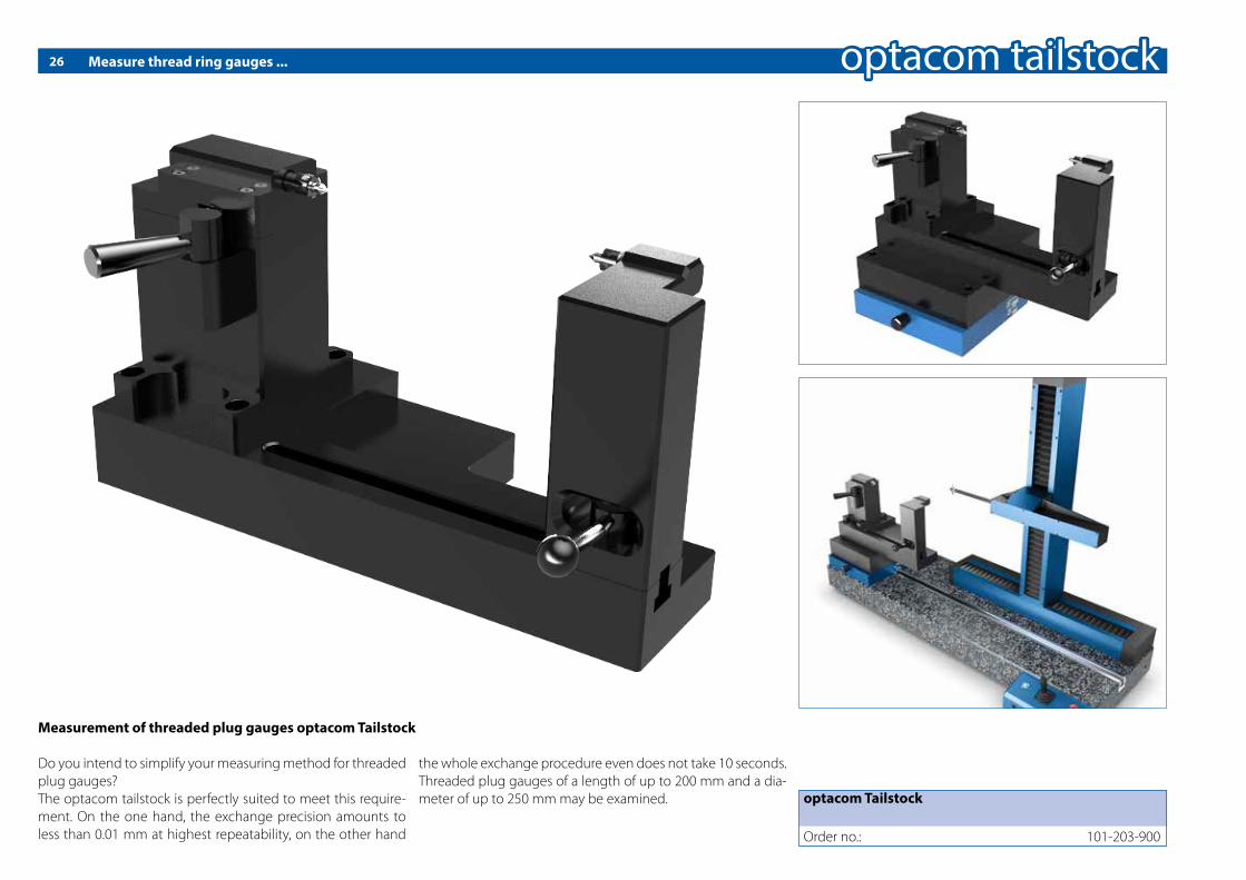
Measurement of threaded plug gauges optacom Tailstock
Do you intend to simplify your measuring method for threaded plug gauges?The optacom tailstock is perfectly suited to meet this require-ment. On the one hand, the exchange precision amounts to less than 0.01 mm at highest repeatability, on the other hand
the whole exchange procedure even does not take 10 seconds. Threaded plug gauges of a length of up to 200 mm and a dia-meter of up to 250 mm may be examined.
26
optacom Tailstock
Order no.: 101-203-900

Accessoires 27
TailstockOnly combined with basis with zero tension, order no.: 101-207-011 and automatic Y table, order no.:101-204-007
Tailstock
Order no.: 101-203-900
Carrying Case Stylus Tips M Threadeach 1x: 101-730-M2,5, 101-730-M03, 101-730-M04, 101-730-M5-8, 101-730-M8-10, 101-730-M10-30/L8, 101-730-M14-30/L10, 101-730-M40, 101-730-M100, 101-632-M2,5, 101-632-5M8, 101-632-8M10, 101-632-10M30, 101-632-M30A, 101-632-M30B, 101-632-M03, 101-632-M04Carrying Case Stylus Tips M Thread
Order no.: 101-207-003
Carrying Case Stylus Tips Trapezoid Threadeach 1x: 101-731-T08, 101-731-T16, 101-731-T22/D1,1, 101-731-T22/D2, 101-632-3M8, 101-632-10M30, 101-633-TSD2
Carrying Case Stylus Tips Trapezoid Thread
Order no.: 101-207-014
Basis with zero tensionOnly combined with automatic Y table
Basis with zero tension
Order no.: 101-207-011
Automatic Y table YTA-25Y-movement range: 25 mm
Automatic Y table YTA-25
Order no.: 101-204-007
Spare parts28
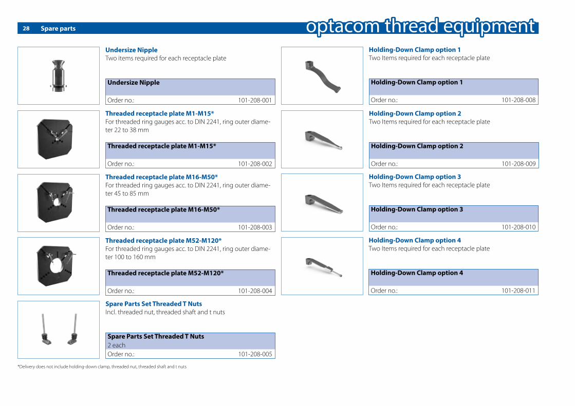
Spare Parts Set Threaded T NutsIncl. threaded nut, threaded shaft and t nuts
Spare Parts Set Threaded T Nuts2 eachOrder no.: 101-208-005
Holding-Down Clamp option 1Two Items required for each receptacle plate
Holding-Down Clamp option 1
Order no.: 101-208-008
Holding-Down Clamp option 2Two Items required for each receptacle plate
Holding-Down Clamp option 2
Order no.: 101-208-009
Holding-Down Clamp option 4Two Items required for each receptacle plate
Holding-Down Clamp option 4
Order no.: 101-208-011
Holding-Down Clamp option 3Two Items required for each receptacle plate
Holding-Down Clamp option 3
Order no.: 101-208-010
Threaded receptacle plate M1-M15*For threaded ring gauges acc. to DIN 2241, ring outer diame-ter 22 to 38 mm
Threaded receptacle plate M16-M50*For threaded ring gauges acc. to DIN 2241, ring outer diame-ter 45 to 85 mm
Threaded receptacle plate M52-M120*For threaded ring gauges acc. to DIN 2241, ring outer diame-ter 100 to 160 mm
Threaded receptacle plate M1-M15*
Order no.: 101-208-002
Threaded receptacle plate M16-M50*
Order no.: 101-208-003
Threaded receptacle plate M52-M120*
Order no.: 101-208-004
Undersize NippleTwo items required for each receptacle plate
Undersize Nipple
Order no.: 101-208-001
*Delivery does not include holding-down clamp, threaded nut, threaded shaft and t nuts

Accessoires 29
Bolts ø 8 mm for thread testing equipmentTwo Items required for each receptacle plate
Bolts ø 8 mm for thread testing equipment
Order no.: 101-208-012
Bolts ø 10 mm for thread testing equipmentTwo Items required for each receptacle plate
Bolts ø 10 mm for thread testing equipment
Order no.: 101-208-013
Bolts ø 11 mm for thread testing equipmentTwo Items required for each receptacle plate
Bolts ø 11 mm for thread testing equipment
Order no.: 101-208-014
Bolts ø 18 mm for thread testing equipmentTwo Items required for each receptacle plate
Bolts ø 18 mm for thread testing equipment
Order no.: 101-208-015
Bolts ø 22 mm for thread testing equipmentTwo Items required for each receptacle plate
Bolts ø 22 mm for thread testing equipment
Order no.: 101-208-016
Bolts ø 24 mm for thread testing equipmentTwo Items required for each receptacle plate
Bolts ø 24 mm for thread testing equipment
Order no.: 101-208-017
Bolts ø 28 mm for thread testing equipmentTwo Items required for each receptacle plate
Bolts ø 28 mm for thread testing equipment
Order no.: 101-208-018
Carrying Case Stylus Tips M Threadeach 1x: 101-730-M2,5, 101-730-M03, 101-730-M04, 101-730-M5-8, 101-730-M8-10, 101-730-M10-30/L8, 101-730-M14-30/L10, 101-730-M40, 101-730-M100, 101-632-M2,5, 101-632-5M8, 101-632-8M10, 101-632-10M30, 101-632-M30A, 101-632-M30B, 101-632-M03, 101-632-M04Carrying Case Stylus Tips M Thread
Order no.: 101-207-003
Carrying Case Stylus Tips Trapezoid Threadeach 1x: 101-731-T08, 101-731-T16, 101-731-T22/D1,1, 101-731-T22/D2, 101-632-3M8, 101-632-10M30, 101-633-TSD2
Carrying Case Stylus Tips Trapezoid Thread
Order no.: 101-207-014

30 Tough, universal, accurate - the perfect addition to your measuring machine
Tough, universal, accurate - optacom Y-tables - the perfect ad-dition to your measuring machine.
Y-tables from optacom are universal, �exible, tough and highly accurate. All in all typical optacom components.They are compact and their linear guides and ball screw drives allow a play-free and accurate movement.
The automatic Y-table also features a stepper motor and an op-tical, incremental and contactless measuring system.
optacom o�ers you the following three di�erent versions:
Y-table manual YTMTo manually search for the highest / lowest point
Y-table automatic YTA-25 / YTA-100To automatically search for the highest / lowest point
For the extension of automated CNC programms on the Y axis to obtain user-independent, reproducible top-down measure-ments in the micrometer range
Automatic Y-table YTA-25 with 25 mm movement rangeOrder no.: 101-204-007
Automatic Y-table YTA-100 with 100 mm movement rangeOrder no.: 101-204-107
Manual Y-table YTM-25 with 25 mm movement rangeOrder no.: 101-204-004
The following speci�cations apply to all Y-tables:YTA-25/YTM-25 length: 185 mm YTA-100 length: 375 mmWidth: 250 mmHeight: 85 mmY-movement range: 25 mm or 100 mmSpindle pitch: 3 mmYTA-25 YTM-25 weight: 11 kgYTA-100 weight: 17 kgTable load: 500 kg

31Simply versatile - The rotary-swiveling table for all measuring tasks
The rotary swiveling table RSY-240-25 from optacom com-bines the advantages of a round table with the advantages of a swiveling holder. Therefore in addition to roundness measu-rements this measuring table focuses especially on the auto-mated and metro logically exact comprehensible swiveling of components. For the �rst time it is possible to measure con-sistently under clearly de�ned conditions. Components with deep grooves and 90° insertions capture �atness and round-ness values that require multiple measurement passes and combine the results of these individual measurements in an error free overall measurement report. Therefore the measu-rement is entirely simpli�ed and more precise. The results are noticeable reduced by monitoring and evaluation.The optacom RSY-240-25 works ultra-precisely, like all our components. The default concentricity is achieved through a mechanical accuracy of 2.5 microns which can be increased by using special chucks to a value below 0.5 micron.By default the RSY 240-25 is delivered with a special developed motorized Y-table with a measuring system and movement range of 25 mm. The integrated Y-table provides the ability to automatically search for the highest / lowest point and allows the expansion of the CNC mode on the Y Axis.
Length: 365 mmWidth: 145 mmHeight: 255 mmY-movement range: 25 mmSpindle pitch: 3 mmSwivel angle: + / -120°Weight: 30 kgMaximum work piece weight: 15 kg
The standard RSY 240-25 is delivered with a manual 3-jaw chuck
4 Fully integrated in the optacom software4 Easy roundness measurement4 Absolute torsion resistant4 In-Out clamping4 Swing diameter over granite base of 190 mm4 Roughness fully measurable on the diameter at circumference4 Fully CNC programmable4Movement controllable via machine console provided with buttons and joystick4 Three integrated optical, incremental and contactless measuring systems
Rotary-swiveling table
Order no.: 101-710-010
Rotary-swiveling table with through-loading max. ø 29 mmOrder no.: 101-710-029
4-times good ...
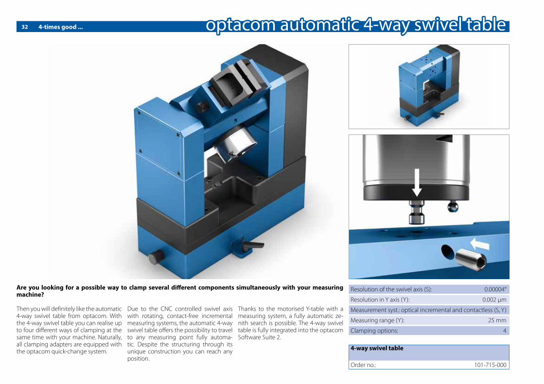
Are you looking for a possible way to clamp several di�erent components simultaneously with your measuring machine?
Then you will de�nitely like the automatic 4-way swivel table from optacom. With the 4-way swivel table you can realise up to four di�erent ways of clamping at the same time with your machine. Naturally, all clamping adapters are equipped with the optacom quick-change system.
Due to the CNC controlled swivel axis with rotating, contact-free incremental measuring systems, the automatic 4-way swivel table o�ers the possibility to travel to any measuring point fully automa-tic. Despite the structuring through its unique construction you can reach any position.
Thanks to the motorised Y-table with a measuring system, a fully automatic ze-nith search is possible. The 4-way swivel table is fully integrated into the optacom Software Suite 2.
4-way swivel table
Order no.: 101-715-000
Resolution of the swivel axis (S): 0.00004°
Resolution in Y axis (Y): 0.002 µm
Measurement syst.: optical incremental and contactless (S, Y)
Measuring range (Y): 25 mm
Clamping options: 4
32

Simply thrilling ...
Are you looking for a possible way to clamp components easily and centrically?
Then you will de�nitely like our completely encapsulated op-tacom centric clamping vice made out of high-strengthen alu-minium. Through the optional available, di�erent, quick to change, hard anodised clamping jaws the widely varying components until 50 mm can be clamped perfectly centrically.
Even thermal expansion is ensured through the centric spindle bearing. In most cases, due to the high centring and repetition accuracy a zenith search after changing parts is not necessary anymore. Our centric clamping vice is equipped standardly with the op-tacom quick-change system.
Dimensions (W x D x H): 145 x 70 x 64 mm
Clamping range w.clamp. jaws for ring clamp.: max. 140 mm
Jaw width: 70 mm
Jaw height (standard): 35 mm
Material: high-strength aircraft aluminium
Centre clamping vice with standard jaws
Order no.: 101-202-100
Clamping jaws for spindle clampingSetOrder no.: 101-202-101
Clamping jaws for ring clampingSetOrder no.: 101-202-102
Flat clamping jawsSetOrder no.: 101-202-103
33
34 The extension module for composite top-down measurements
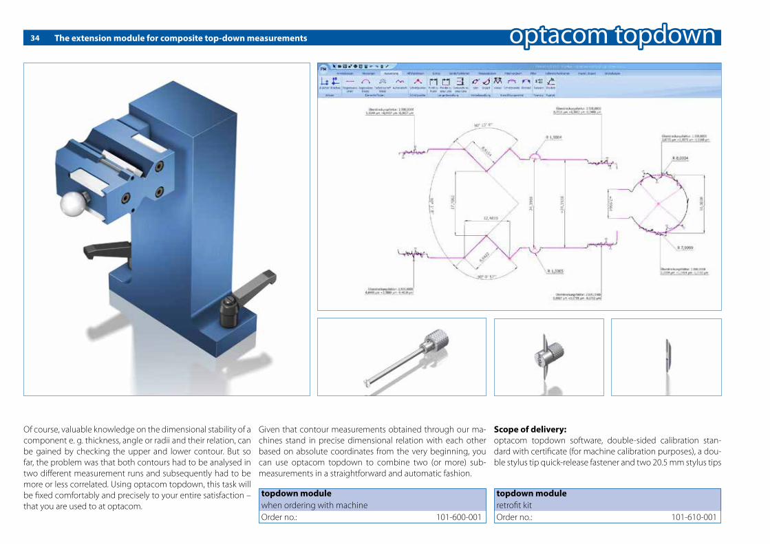
Of course, valuable knowledge on the dimensional stability of a component e. g. thickness, angle or radii and their relation, can be gained by checking the upper and lower contour. But so far, the problem was that both contours had to be analysed in two di�erent measurement runs and subsequently had to be more or less correlated. Using optacom topdown, this task will be �xed comfortably and precisely to your entire satisfaction – that you are used to at optacom.
Given that contour measurements obtained through our ma-chines stand in precise dimensional relation with each other based on absolute coordinates from the very beginning, you can use optacom topdown to combine two (or more) sub-measurements in a straightforward and automatic fashion.
Scope of delivery:optacom topdown software, double-sided calibration stan-dard with certi�cate (for machine calibration purposes), a dou-ble stylus tip quick-release fastener and two 20.5 mm stylus tips
topdown moduleretro�t kitOrder no.: 101-610-001
topdown modulewhen ordering with machineOrder no.: 101-600-001
35Clamping with simplicity
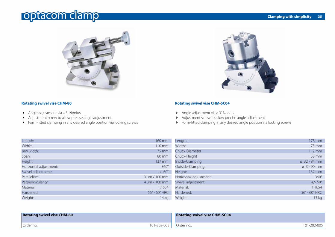
Length: 160 mmWidth: 110 mmJaw width: 75 mmSpan: 80 mmHeight: 137 mmHorizontal adjustment: 360°Swivel adjustment: +/- 60°Parallelism: 3 μm / 100 mmPerpendicularity: 4 μm / 100 mmMaterial: 1.1654Hardened: 56° - 60° HRCWeight: 14 kg
Rotating swivel vise CHM-80
Order no.: 101-202-003
Rotating swivel vise CHM-80
4 Angle adjustment via a 3‘-Nonius4 Adjustment screw to allow precise angle adjustment4 Form-�tted clamping in any desired angle position via locking screws
Length: 178 mmWidth: 75 mmChuck-Diameter 112 mmChuck-Height 58 mmInside-Clamping ø 32 - 84 mmOutside-Clamping ø 3 - 90 mmHeight: 137 mmHorizontal adjustment: 360°Swivel adjustment: +/- 60°Material: 1.1654Hardened: 56° - 60° HRCWeight: 13 kg
Rotating swivel vise CHM-SC04
Order no.: 101-202-005
Rotating swivel vise CHM-SC04
4 Angle adjustment via a 3‘-Nonius4 Adjustment screw to allow precise angle adjustment4 Form-�tted clamping in any desired angle position via locking screws

Clamping with simplicity36
Standard vise A-25
4 Made out of high-quality alloy steel, hardened and grinded4 Very precise, closes absolutely gap-free4 Two integrated side clamping slots
Sine angle vise SA-100
4 Made out of high-quality alloy steel, hardened and grinded4 Angle adjustment via gauge blocks4 Clamping system at the lower part allows a secure angle adjustment
Length: 130 mmWidth: 73 mmSpan: 45 mmHeight: 93 mmSwivel adjustment: 45°Parallelism: 3 μm / 100 mmPerpendicularity: 5 μm / 100 mmMaterial: 1.1654Hardened: 58° - 62° HRCWeight: 6 kg
Length: 140 mmWidth: 63 mmSpan: 85 mmHeight: 69 mmParallelism: 3 μm / 100 mmPerpendicularity: 4 μm / 100 mmMaterial: 1.1654Hardened: 56° - 58° HRCWeight: 4.6 kg
Sine angle vise SA-100
Order no.: 101-202-010
Standard vise A-25
Order no.: 101-202-020
37
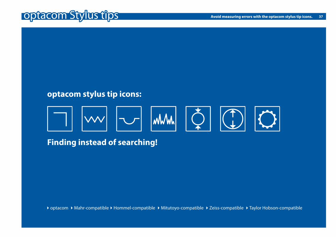
4optacom 4Mahr-compatible 4Hommel-compatible 4Mitutoyo-compatible 4Zeiss-compatible 4Taylor Hobson-compatible4optacom 4Mahr-compatible4Hommel-compatible 4Mitutoyo-compatible 4Zeiss-compatible 4Taylor Hobson-compatible
optacom stylus tip icons:
Finding instead of searching!
Avoid measuring errors with the optacom stylus tip icons.

38 Icon explanation
Angle: This stylus tip is well suited to measure threads and parts with a pitch.
Thread: This stylus tip is well suited to measure threads, ball screws and parts with a pitch.
Track: This stylus tip is well suited to measure parts with symmetric contour. For example - ball screws.
Roughness: This stylus tip is well suited to measure roughness
Top/down external: This stylus tip is best used for top/down measurement.
Top/down internal: This stylus tip is best used for top/down measurements within drill holes.
Gear: This stylus tip is well suited for measurements of geometries in combination with our RSY 240-25. For example – gear wheels.
optacom
approved quality - Made in G
erm
any
optacom stylus tip icons:
Finding instead of searching!
39
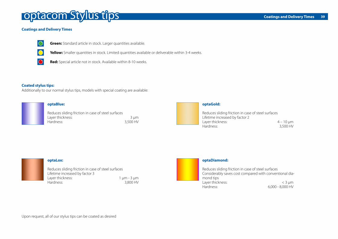
Green: Standard article in stock. Larger quantities available.
Yellow: Smaller quantities in stock. Limited quantities available or deliverable within 3-4 weeks.
Red: Special article not in stock. Available within 8-10 weeks.
Upon request, all of our stylus tips can be coated as desired
Coatings and Delivery Times
Coatings and Delivery Times
optaBlue:
Reduces sliding friction in case of steel surfacesLayer thickness: 3 μmHardness: 3,500 HV
optaGold:
Reduces sliding friction in case of steel surfacesLifetime increased by factor 2Layer thickness: 4 – 10 µmHardness: 3,500 HV
optaLox:
Reduces sliding friction in case of steel surfacesLifetime increased by factor 3Layer thickness: 1 μm - 3 μmHardness: 3,800 HV
optaDiamond:
Reduces sliding friction in case of steel surfacesConsiderably saves cost compared with conventional dia-mond tipsLayer thickness: < 3 μmHardness: 6,000 - 8,000 HV
Coated stylus tips:Additionally to our normal stylus tips, models with special coating are available:
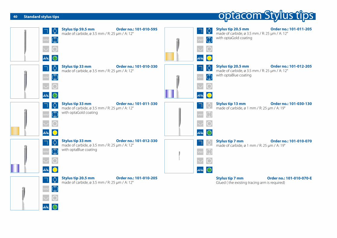
Standard stylus tips40
Stylus tip 59.5 mm Order no.: 101-010-595made of carbide, ø 3.5 mm / R: 25 μm / A: 12°
Stylus tip 33 mm Order no.: 101-010-330made of carbide, ø 3.5 mm / R: 25 μm / A: 12°
Stylus tip 33 mm Order no.: 101-011-330made of carbide, ø 3.5 mm / R: 25 μm / A: 12°with optaGold coating
Stylus tip 33 mm Order no.: 101-012-330made of carbide, ø 3.5 mm / R: 25 μm / A: 12°with optaBlue coating
Stylus tip 20.5 mm Order no.: 101-010-205made of carbide, ø 3.5 mm / R: 25 μm / A: 12°
Stylus tip 20.5 mm Order no.: 101-011-205made of carbide, ø 3.5 mm / R: 25 μm / A: 12°with optaGold coating
Stylus tip 20.5 mm Order no.: 101-012-205made of carbide, ø 3.5 mm / R: 25 μm / A: 12°with optaBlue coating
Stylus tip 13 mm Order no.: 101-030-130made of carbide, ø 1 mm / R: 25 μm / A: 19°
Stylus tip 7 mm Order no.: 101-010-070made of carbide, ø 1 mm / R: 25 μm / A: 19°
Stylus tip 7 mm Order no.: 101-010-070-E Glued ( the existing tracing arm is required)

Standard stylus tips 41
Stylus tip 6 mm Order no.: 101-010-060made of carbide, ø 1 mm / R: 25 μm / A: 19°
Stylus tip 3.5 mm Order no.: 101-030-035made of carbide, ø 0.5 mm / R: 25 μm / A: 19°
Stylus tip 4.5 mm Order no.: 101-010-045made of carbide, ø 1 mm / R: 25 μm / A: 19°
Stylus tip 2.5 mm Order no.: 101-010-025made of carbide, ø 0.5 mm / R: 25 μm / A: 19°
Stylus tip 2.5 mm Order no.: 101-010-025-E Glued ( the existing tracing arm is required)
Stylus tip 6 mm Order no.: 101-010-060-E Glued ( the existing tracing arm is required)
Stylus tip 4.5 mm Order no.: 101-010-045-E Glued ( the existing tracing arm is required)

Standard stylus tips42
Stylus tip 10 mm Order no.: 101-010-100made of carbide, ø 1 mm / R: 25 μm / A: 19°
Stylus tip 105 mm Order no.: 101-010-105made of carbide, ø 3.5 mm / R: 25 μm / A: 12°
Stylus tip 25 mm Order no.: 101-010-250made of carbide, ø 1 mm / R: 25 μm / A: 19°
Stylus tip 90 mm Order no.: 101-010-900made of carbide, ø 3.5 mm / R: 25 μm / A: 12°

Standard stylus tips 43
Stylus tip 20.5 mm conical Order no.: 101-130-620made of carbide, ø 3.5 mm / R: 60 µm
Stylus tip 20.5 mm conical Order no.: 101-134-005made of carbide, ø 3.5 mm, R: 0,05 mm / A: 24°
Stylus tip 20.5 mm conical Order no.: 101-134-010made of carbide, ø 3.5 mm, R: 0,1 mm / A: 24°
Stylus tip 12 mm conical Order no.: 101-140-121made of carbide, ø 1 mm / R: 25 µm / A: 20°

Conical stylus tips44
Stylus tip 33 mm conical Order no.: 101-110-330made of carbide, ø 3.5 mm / R: 25 μm / A: 24°
Stylus tip 20.5 mm conical Order no.: 101-110-205made of carbide, ø 3.5 mm / R: 25 μm / A: 24°
Stylus tip 59.5 mm conical Order no.: 101-110-595made of carbide, ø 3.5 mm / R: 25 μm / A: 24°
Stylus tip 33 mm conical Order no.: 101-111-330made of carbide, ø 3.5 mm / R: 25 μm / A: 24°with optaLox coating
Stylus tip 20.5 mm conical Order no.: 101-111-205made of carbide, ø 3.5 mm / R: 25 μm / A: 24°with optaLox coating
Stylus tip 6 mm conical Order no.: 101-110-060made of carbide, ø 1 mm / R: 25 µm / A: 24°
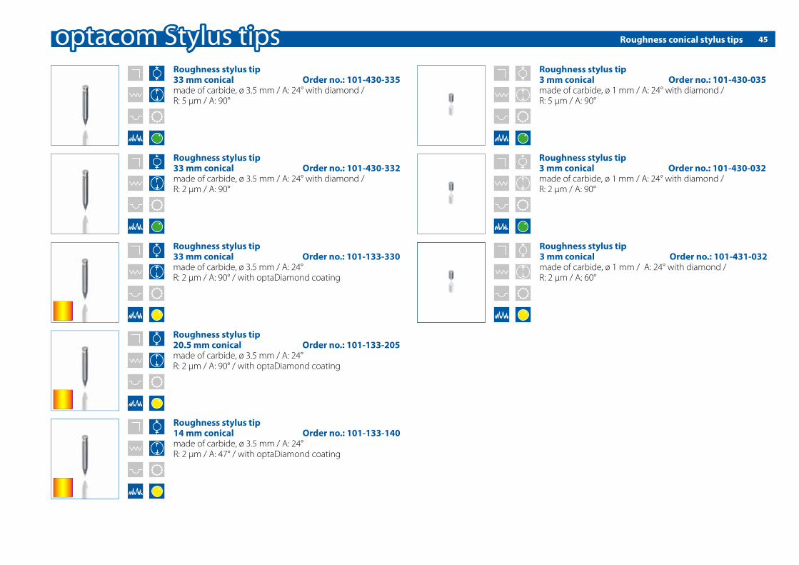
Roughness conical stylus tips 45
Roughness stylus tip3 mm conical Order no.: 101-430-035made of carbide, ø 1 mm / A: 24° with diamond / R: 5 μm / A: 90°
Roughness stylus tip3 mm conical Order no.: 101-430-032made of carbide, ø 1 mm / A: 24° with diamond / R: 2 μm / A: 90°
Roughness stylus tip33 mm conical Order no.: 101-430-332made of carbide, ø 3.5 mm / A: 24° with diamond / R: 2 μm / A: 90°
Roughness stylus tip33 mm conical Order no.: 101-430-335made of carbide, ø 3.5 mm / A: 24° with diamond / R: 5 μm / A: 90°
Roughness stylus tip3 mm conical Order no.: 101-431-032made of carbide, ø 1 mm / A: 24° with diamond / R: 2 μm / A: 60°
Roughness stylus tip20.5 mm conical Order no.: 101-133-205made of carbide, ø 3.5 mm / A: 24°R: 2 μm / A: 90° / with optaDiamond coating
Roughness stylus tip 33 mm conical Order no.: 101-133-330made of carbide, ø 3.5 mm / A: 24°R: 2 μm / A: 90° / with optaDiamond coating
Roughness stylus tip 14 mm conical Order no.: 101-133-140made of carbide, ø 3.5 mm / A: 24°R: 2 μm / A: 47° / with optaDiamond coating

Conical double stylus tips 46
Double-Tastsp. 9 mm conical Order no.: 101-330-090made of carbide, ø 1 mm / R: 25 μm / A: 2 x 24°for topdown measurements
Double-Tastsp. 6 mm conical Order no.: 101-330-060made of carbide, ø 1 mm / R: 25 μm / A: 2 x 24°for topdown measurements
Double-Stylus tip 13 mmconical Order no.: 101-330-130made of carbide, ø 2 mm / R: 25 µm / double-sided cone 24°
Double-Stylus tip 12 mmconical Order no.: 101-330-120made of carbide, ø 3.5 mm / R: 0.1 mm / with double-sided cone 48°
Double-Stylus tip 18 mmconical Order no.: 101-330-180made of carbide, ø 2 mm / R: 25 µm / double-sided cone 24°
Double-Stylus tip 4.4-24°-0.7conical Order no.: 101-330-044made of carbide, ø 1 x 4.4 mm / R: 25 µm / with double-sided cone 24° x 0.7 mm long
Double-Stylus tip 4.4-48°-0.7conical Order no.: 101-330-144made of carbide, ø 1 x 4.4 mm / R: 25 µm / with double-sided cone 48° x 0.7 mm long
Double-Stylus tip 25 mmconical Order no.: 101-330-250made of carbide, ø 2 mm / R: 25 µm / A: 2 x 24 °for topdown measurements
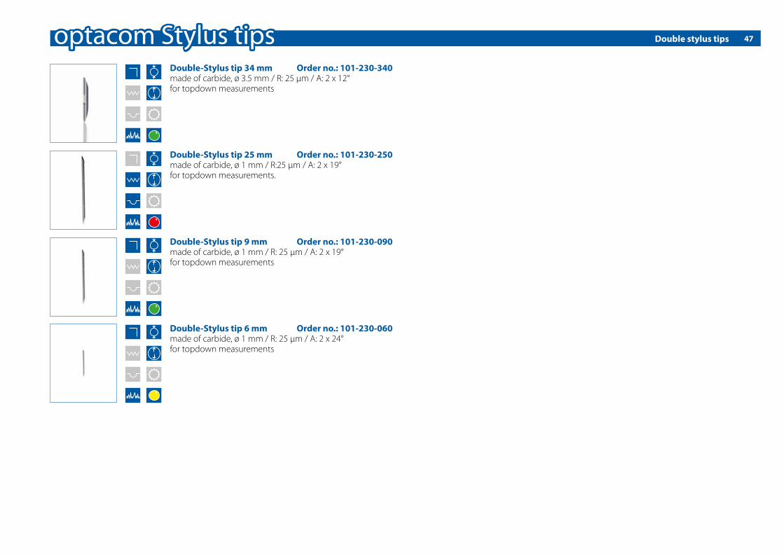
Double stylus tips 47
Double-Stylus tip 34 mm Order no.: 101-230-340made of carbide, ø 3.5 mm / R: 25 μm / A: 2 x 12°for topdown measurements
Double-Stylus tip 9 mm Order no.: 101-230-090made of carbide, ø 1 mm / R: 25 μm / A: 2 x 19°for topdown measurements
Double-Stylus tip 6 mm Order no.: 101-230-060made of carbide, ø 1 mm / R: 25 μm / A: 2 x 24°for topdown measurements
Double-Stylus tip 25 mm Order no.: 101-230-250made of carbide, ø 1 mm / R:25 µm / A: 2 x 19°for topdown measurements.
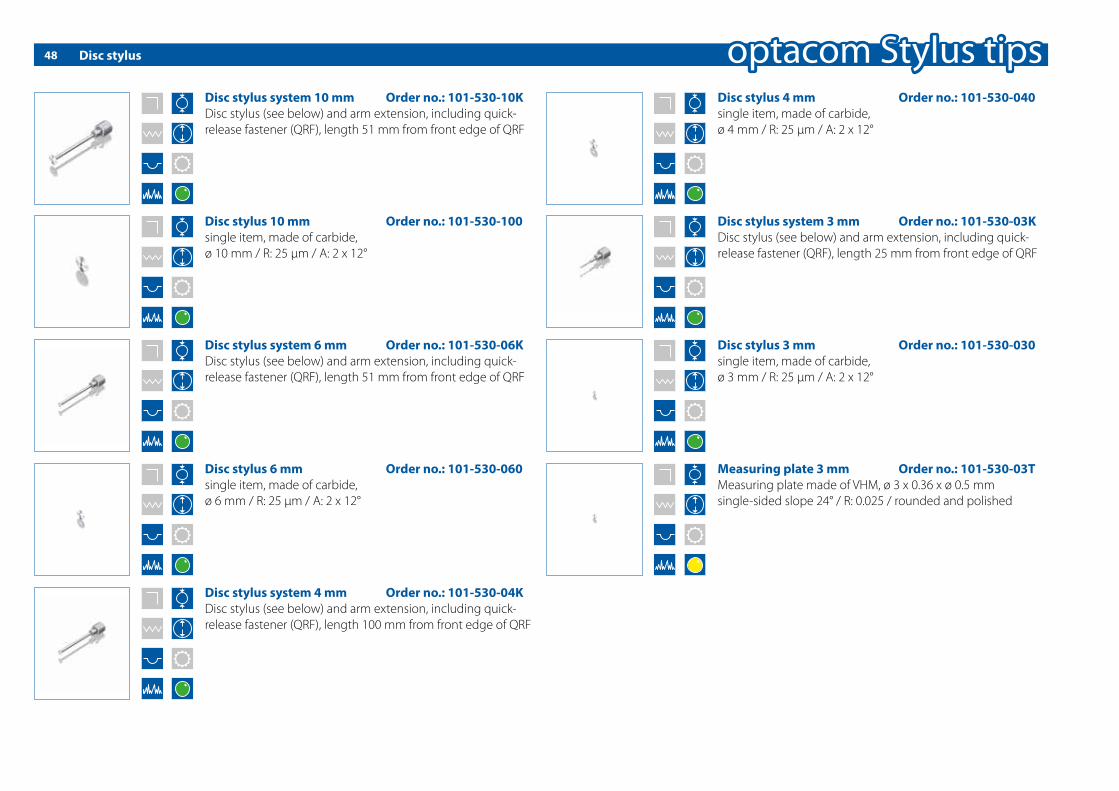
Disc stylus48
Disc stylus 10 mm Order no.: 101-530-100single item, made of carbide, ø 10 mm / R: 25 μm / A: 2 x 12°
Disc stylus system 10 mm Order no.: 101-530-10KDisc stylus (see below) and arm extension, including quick-release fastener (QRF), length 51 mm from front edge of QRF
Disc stylus system 6 mm Order no.: 101-530-06KDisc stylus (see below) and arm extension, including quick-release fastener (QRF), length 51 mm from front edge of QRF
Disc stylus 6 mm Order no.: 101-530-060single item, made of carbide, ø 6 mm / R: 25 μm / A: 2 x 12°
Disc stylus 3 mm Order no.: 101-530-030single item, made of carbide, ø 3 mm / R: 25 μm / A: 2 x 12°
Disc stylus system 3 mm Order no.: 101-530-03KDisc stylus (see below) and arm extension, including quick-release fastener (QRF), length 25 mm from front edge of QRF
Disc stylus system 4 mm Order no.: 101-530-04KDisc stylus (see below) and arm extension, including quick-release fastener (QRF), length 100 mm from front edge of QRF
Disc stylus 4 mm Order no.: 101-530-040single item, made of carbide, ø 4 mm / R: 25 μm / A: 2 x 12°
Measuring plate 3 mm Order no.: 101-530-03TMeasuring plate made of VHM, ø 3 x 0.36 x ø 0.5 mmsingle-sided slope 24° / R: 0.025 / rounded and polished

Disc stylus 49
Disc stylus system 1 mm Order no.: 101-530-01KDisc stylus (see below) incl. quick-release fastener (QRF)
Disc stylus 1 mm Order no.: 101-530-010single item, ø 1 mm / R: 25 μm / A: 2 x 12°, including exension (made of one piece - carbide), length 25 mm from front edge of quick-release fastener

Quick-release fastener and miniature stylus arms50
Miniature stylus arm for removable stylus tip ø 1 mm incl. allen key Order no.: 101-631-060including QRF, standard length 50 mm(other lengths upon request); delivery without stylus tips!
Miniature stylus arm with glued ø 0.5 mmStylus tip / length 3.5 mm Order no.: 101-631-035including QRF, standard length 35 mm (other lengths upon request)
Quick-release fastener Order no.: 101-630-035for Stylus tips with diameters of 3.5 mm
topdown-Quick-release fastener Order no.: 101-630-0TDfor Stylus tips with diameters 3.5 mm for topdown measure-ments; delivery without stylus tips!
Quick-release fastener Order no.: 101-630-040for stylus tips and absorption for dial test indicator with ø 4 mm
Clamping shaftfor dial test indicator ø $ H7 Order no.: 101-631-065needs Quick-release fastener Order no.: 101-630-040
Miniature stylus arm for removable stylus tip ø 2 mm incl. allen key Order no.: 101-631-062including QRF, standard length 150 mm(other lengths upon request); delivery without stylus tips!
Miniature stylus arm for �ush-bondedStylus tip ø 1 mm Order no.: 101-631-010including QRF, standard length 50 mm; delivery without stylus tips!
Miniature stylus arm with glued ø 0.5 mmStylus tip / length 2.5 mm Order no.: 101-631-025including QRF, standard length 35 mm (other lengths upon request)
Miniature stylus arm for �ush-bondedStylus tip ø 1 mm Order no.: 101-631-011including QRF, standard length 100 mm; delivery without stylus tips!

Miniature stylus arm 51
Miniature stylus arm with stylus tip ø 3.5 mm incl. allen key Order no.: 101-631-QA1including QRF, standard length 25 mm, length of cross arm 25 mm; delivery without stylus tips!
Miniature stylus arm with stylus tip ø 3.5 mm incl. allen key Order no.: 101-631-QA3,5including QRF, standard length 50 mm, length of cross arm 25 mm; delivery without stylus tips!
Small diamond stylus arm Order no.: 101-633-0KLClamping ø 3 mm, measurement length 5 mm, shaft ø 1 mm; for topdown roughness measurements in slots and cut-ins min. width of 2 mm.

Special stylus tips und ceramics stylus tips52
Special-Stylus tip 20.5 mm conical Order no.: 101-130-120made of carbide, ø 3.5 mm / R: 0.1 mm / L: 5 mm / A: 10°
Special-Stylus tip 20.5 mm conical Order no.: 101-130-420made of carbide, ø 3.5 mm / R: 0.45 mm / L: 5 mm / A: 10°
Special-Stylus tip 20.5 mm Order no.: 101-030-620made of carbide, ø 3.5 mm / R: 25 µm / A: 6° L: 3 mm
Special-Stylus tip 20.5 mm Order no.: 101-030-820made of carbide, ø 3.5 mm / R: 25 µm / A: 8° L: 10 mm
Special-Stylus tip 16.35 mm conical Order no.: 101-030-16,35made of carbide, ø 3.5 mm / R: 25 µm / A: 16°
Special-Stylus tip 20.5 mm Order no.: 101-030-628made of carbide, ø 3.5 mm / R: 25 µm / 6° auf 8 mm
Special-Stylus tip 13 mm Order no.: 101-830-130made of carbide, ø 2 x ø 1 mm / R: 25 µm / A: 12°
Ceramic Stylus tip 14 mm conical Order no.: 101-641-140made of ceramics, ø 3.5 mm / R: 5 µm / A: 24°
Ceramic Stylus tip 20.5 mm conical Order no.: 101-641-205made of ceramics, ø 3.5 mm / R: 25 µm / A: 24°
Ceramic Stylus tip 33 mm Order no.: 101-640-330made of ceramics, ø 3.5 mm / R: 25 µm / A: 12°
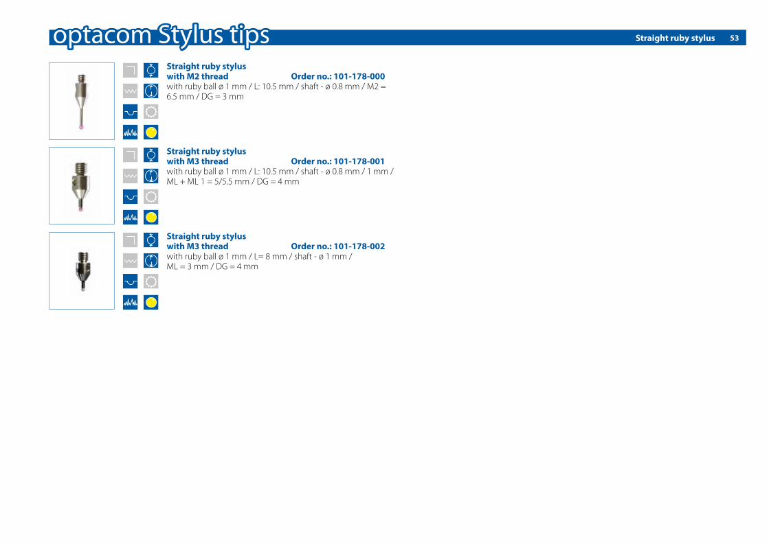
Straight ruby stylus 53
Straight ruby stylus with M2 thread Order no.: 101-178-000with ruby ball ø 1 mm / L: 10.5 mm / shaft - ø 0.8 mm / M2 = 6.5 mm / DG = 3 mm
Straight ruby stylus with M3 thread Order no.: 101-178-001with ruby ball ø 1 mm / L: 10.5 mm / shaft - ø 0.8 mm / 1 mm / ML + ML 1 = 5/5.5 mm / DG = 4 mm
Straight ruby stylus with M3 thread Order no.: 101-178-002with ruby ball ø 1 mm / L= 8 mm / shaft - ø 1 mm / ML = 3 mm / DG = 4 mm

Stylus tips for trapezoidal threads54
Stylus tip for trapezoidal threads8x1.5 - 14x3 Order no.: 101-731-T08made of carbide, ø 0.6 / R: 50 µm / A: 2 x 22.5° / length 6 mm, for topdown measurements
Stylus tip for trapezoidal threads16x2 - 20x4 Order no.: 101-731-T16made of carbide, ø 1.1 / R: 50 µm / A: 2 x 22.5° / length 11 mm, for topdown measurements
Stylus tip for trapezoidal threads22x3 - 60x9 Order no.: 101-731-T22/D1,1made of carbide, ø 1.1 / R: 50 µm / A: 2 x 22.5° / length 17 mm, for topdown measurements
Stylus tip for trapezoidal threads22x3 - 60x9 Order no.: 101-731-T22/D2made of carbide, ø 2 / R: 50 µm / A: 2 x 22.5° / length 17 mm, for topdown measurements
Carrying case with styli for trapezoidal threadsincludes each 1x: 101-731-T08, 101-731-T16, 101-731-T22/D1,1, 101-731-T22/D2, 101-632-3M8, 101-632-10M30, 101-633-TSD2
Carrying case with styli for trapezoidal threads
Order no.: 101-207-014

Stylus tips for threads 55
Stylus tips for M3 threads Order no.: 101-730-M03made of carbide, ø 0.6 h6 / R: 50 µm / A: 2 x 45° / length 2.2 mm, for topdown measurements
Stylus tips for M4 threads Order no.: 101-730-M04made of carbide, ø 0.6 h6 / R: 50 µm / A: 2 x 37.5° / length 3 mm, for topdown measurements
Stylus tips for M14-M30 threads Order no.: 101-730-M14-30/L10made of carbide, ø 1.1 h6 / R: 50 µm / A: 2 x 37.5° / length 10 mm, for topdown measurements
Stylus tips for M10-M30 threads Order no.: 101-730-M10-30/L8made of carbide, ø 1.1 h6 / R: 50 µm / A: 2 x 37.5° / length 8 mm, for topdown measurements
Stylus tips for > M100 threads Order no.: 101-730-M100made of carbide, ø 5 h6 / R: 50 µm / A: 2 x 37.5° / length 50 mm, for topdown measurements
Stylus tips for > M40 threads Order no.: 101-730-M40made of carbide, ø 3.5 h6 / R: 50 µm / A: 2 x 37.5° / length 30 mm, for topdown measurements
Stylus tips for M5-M8 threads Order no.: 101-730-M5-8made of carbide, ø 0.6 h6 / R: 50 µm / A: 2 x 37.5° / length 3.5 mm, for topdown measurements
Stylus tips for M8-M10 threads Order no.: 101-730-M8-10made of carbide, ø 0.8 h6 / R: 50 µm / A: 2 x 37.5° / length 5 mm, for topdown measurements
Stylus tips for M2,5 threads Order no.: 101-730-M2,5made of carbide, ø 0.5 h6 / R: 50 µm / A: 2 x 50° / length 2 mm, for topdown measurements
Carrying case with styli for metric-threadseach 1x: 101-730-M2,5, 101-730-M03, 101-730-M04, 101-730-M5-8, 101-730-M8-10, 101-730-M10-30/L8, 101-730-M14-30/L10, 101-730-M40, 101-730-M100, 101-632-M2,5, 101-632-5M8, 101-632-8M10, 101-632-10M30, 101-632-M30A, 101-632-M30B, 101-632-M03, 101-632-M04Carrying case with styli for metric-threads
Order no.: 101-207-003
Stylus arm for thread styli, fastener for thread stylus tips56
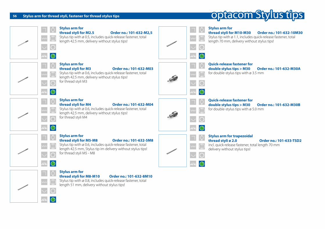
Stylus arm forthread styli for M2.5 Order no.: 101-632-M2,5Stylus tip with ø 0.5, includes quick-release fastener, total length 42.5 mm, delivery without stylus tips!
Stylus arm forthread styli for M5-M8 Order no.: 101-632-5M8Stylus tip with ø 0.6, includes quick-release fastener, total length 42.5 mm, Stylus tip im delivery without stylus tips!for thread styli M5 - M8
Stylus arm forthread styli for M8-M10 Order no.: 101-632-8M10Stylus tip with ø 0.8, includes quick-release fastener, total length 51 mm, delivery without stylus tips!
Stylus arm forthread styli for M10-M30 Order no.: 101-632-10M30Stylus tip with ø 1.1, includes quick-release fastener, total length 70 mm, delivery without stylus tips!
Quick-release fastener fordouble stylus tips > M30 Order no.: 101-632-M30Afor double-stylus tips with ø 3.5 mm
Stylus arm for trapezoidal thread styli ø 2.0 Order no.: 101-633-TSD2incl. quick-release fastener, total length 70 mmdelivery without stylus tips!
Quick-release fastener fordouble stylus tips > M30 Order no.: 101-632-M30Bfor double-stylus tips with ø 5.0 mm
Stylus arm forthread styli for M3 Order no.: 101-632-M03Stylus tip with ø 0.6, includes quick-release fastener, total length 42.5 mm, delivery without stylus tips! for thread styli M3
Stylus arm forthread styli for M4 Order no.: 101-632-M04Stylus tip with ø 0.6, includes quick-release fastener, total length 42.5 mm, delivery without stylus tips!for thread styli M4

Special solutions
A chain is only as strong as its weakest link - a measurement system is only as good as its tracing arm and stylus tip.Thus, we pay serious attention to this detail – as we do to our machines. All stylus systems are manufactured with the same care as optacom´s measurement systems.
Our practice oriented and cost reducing system of various sty-lus tips, disc styli, and miniature tracing arms can be replaced in seconds using the practical optacom quick-release fastener.
This is shown in the daily business of calibration and measuring labs in factories worldwide.
With your input we develop and manufacture e�ective solu-tions to meet your speci�c measurement requirements.
We are looking forward to receive your inquiry.
Miniature stylus arm, angled 90° for 6 mm stylus tip glued at a 45° angle
Miniature tracing arm, angled for 6 mm stylus tip
57

Standard stylus tips58
Stylus tip 59.5 mm Order no.: 101-010-595made of carbide, ø 3.5 mm / R: 25 μm / A: 12°Mahr-compatible (6851517)
Stylus tip 33 mm Order no.: 101-010-330made of carbide, ø 3.5 mm / R: 25 μm / A: 12°Mahr-compatible (6850286)
Stylus tip 20.5 mm Order no.: 101-010-205made of carbide, ø 3.5 mm / R: 25 μm / A: 12°Mahr-compatible (6850289)
Stylus tip 7 mm Order no.: 101-010-070made of carbide, ø 1 mm / R: 25 μm / A: 19°Mahr-compatible vor tracing arm LD C 7-15-25
Stylus tip 4.5 mm Order no.: 101-010-045made of carbide, ø 1 mm / R: 25 μm / A: 19°Mahr-compatible
Stylus tip 2.5 mm Order no.: 101-010-025made of carbide, ø 0.5 mm / R: 25 μm / A: 19°Mahr-compatible
Stylus tip 7 mm Order no.: 101-010-070-E Glued (the existing tracing arm is required)
Stylus tip 2.5 mm Order no.: 101-010-025-E Glued (the existing tracing arm is required)
Stylus tip 4.5 mm Order no.: 101-010-045-E Glued (the existing tracing arm is required)
Stylus tip 6 mm Order no.: 101-010-060made of carbide, ø 1 mm / R: 25 μm / A: 19°Mahr-compatible (6851527)
Stylus tip 6 mm Order no.: 101-010-060-E Glued ( the existing tracing arm is required)
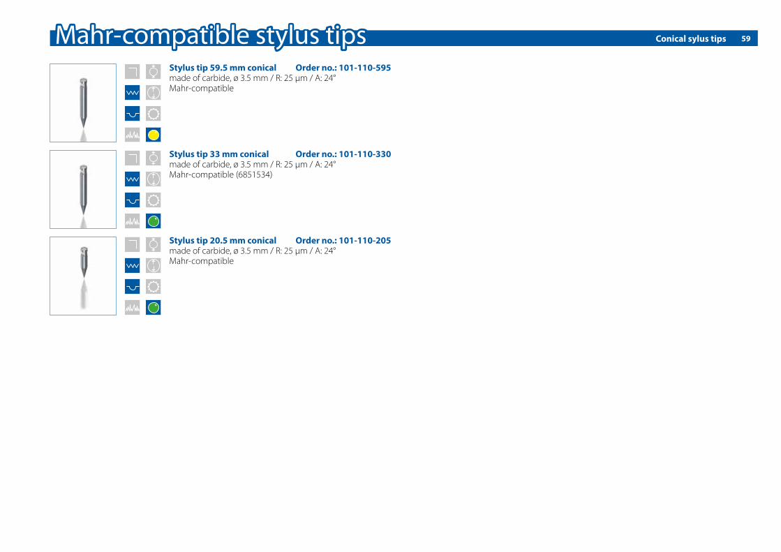
Conical sylus tips 59
Stylus tip 33 mm conical Order no.: 101-110-330made of carbide, ø 3.5 mm / R: 25 μm / A: 24°Mahr-compatible (6851534)
Stylus tip 20.5 mm conical Order no.: 101-110-205made of carbide, ø 3.5 mm / R: 25 μm / A: 24°Mahr-compatible
Stylus tip 59.5 mm conical Order no.: 101-110-595made of carbide, ø 3.5 mm / R: 25 μm / A: 24°Mahr-compatible

60 Standard- and conical stylus tips
Stylus tip 32 mm Order no.: 101-020-320made of carbide, ø 3 mm / R: 20 μm / A: 11° Hommel-compatible (compatible to 284039)
Stylus tip 42 mm Order no.: 101-020-420made of carbide, ø 3 mm / R: 20 μm / A: 11°Hommel-compatible (compatible to 232586)
Stylus tip 52 mm Order no.: 101-020-520made of carbide, ø 3 mm / R: 20 μm / A: 11°Hommel-compatible (compatible to 232633)
Stylus tip 20 mm conical Order no.: 101-120-200made of carbide, ø 1 mm / R: 20 μm / A: 30°Hommel-compatible
Stylus tip 32 mm conical Order no.: 101-120-320made of carbide, ø 3 mm / R: 20 μm / A: 30°Hommel-compatible
Stylus tip 52 mm conical Order no.: 101-120-520made of carbide, ø 3 mm / R: 20 μm / A: 30°Hommel-compatible
Stylus tip 6 mm Order no.: 101-020-060made of carbide, ø 1 mm / R: 20 μm / A: 22° Hommel-compatible
Stylus tip 21 mm Order no.: 101-020-210made of carbide, ø 3 mm / R: 20 μm / A: 11°Hommel-compatible
Stylus tip 6 mm Order no.: 101-020-060-E Glued (the existing tracing arm is required)
Stylus tip 20 mm conical Order no.: 101-120-200-E Glued (the existing tracing arm is required)

61Standard- and conical stylus tips
Stylus tip 26.7 mm conical Order no.: 101-160-267made of carbide, ø 1.6 mm / R: 10 μm / A: 30°Taylor Hobson-compatible
Stylus tip 26.7 mm Order no.: 101-060-267made of carbide, ø 1.6 mm / R: 20 μm / A: 15°Taylor Hobson-compatible (232633)

Standard- and conical stylus tips62
Stylus tip 14 mm conical Order no.: 101-150-140made of carbide, ø 3 mm / R: 25 μm / A: 24°Mitutoyo-compatible
Stylus tip 20 mm conical Order no.: 101-150-200made of carbide, ø 3 mm / R: 25 μm / A: 24°Mitutoyo-compatible
Stylus tip 28 mm conical Order no.: 101-150-280made of carbide, ø 3 mm / R: 25 μm / A: 24°Mitutoyo-compatible
Stylus tip 38 mm conical Order no.: 101-150-380made of carbide, ø 3 mm / R: 25 μm / A: 24°Mitutoyo-compatible
Stylus tip 50 mm conical Order no.: 101-150-500made of carbide, ø 3 mm / R: 25 μm / A: 24°Mitutoyo-compatible
Stylus tip 14 mm Order no.: 101-050-140made of carbide, ø 3 mm / R: 25 μm / A: 11°Mitutoyo-compatible (354882)
Stylus tip 28 mm Order no.: 101-050-280made of carbide, ø 3 mm / R: 25 μm / A: 11°Mitutoyo-compatible (354884)
Stylus tip 38 mm Order no.: 101-050-380made of carbide, ø 3 mm / R: 25 μm / A: 11°Mitutoyo-compatible (354885)
Stylus tip 50 mm Order no.: 101-050-500made of carbide, ø 3 mm / R: 25 μm / A: 11°Mitutoyo-compatible (354886)
Stylus tip 20 mm Order no.: 101-050-200made of carbide, ø 3 mm / R: 25 μm / A: 11°Mitutoyo-compatible (354883)

Standard stylus tips 63
Stylus tip 28 mm Order no.: 101-050-280-0,035made of carbide, ø 3 mm / R: 35 µm / A: 11°Mitutoyo-compatible
Stylus tip 28 mm Order no.: 101-050-280-0,045made of carbide, ø 3 mm / R: 45 µm / A: 11°Mitutoyo-compatible
Stylus tip 28 mm Order no.: 101-050-280-0,075made of carbide, ø 3 mm / R: 75 µm / A: 11°Mitutoyo-compatible
Stylus tip 28 mm Order no.: 101-050-280-0,100made of carbide, ø 3 mm / R: 100 µm / A: 11°Mitutoyo-compatible

Standard stylus tips64
Stylus tip 21 mm Order no.: 101-040-210made of carbide, ø 2 mm / R: 25 μm / A: 11° Zeiss-compatible (DT 45503)
Stylus tip 34 mm Order no.: 101-040-340made of carbide, ø 3 mm / R: 25 μm / A: 11°Zeiss-compatible (DT 45502)
Stylus tip 60 mm Order no.: 101-040-600made of carbide, ø 3 mm / R: 25 μm / A: 11°Zeiss-compatible (DT 45501)
Stylus tip 4.5 mm Order no.: 101-040-045made of carbide, ø 0.8 mm / R: 25 μm / A: 12°Zeiss-compatible (DT 45512 / DT 45083)
Stylus tip 8 mm Order no.: 101-040-080made of carbide, ø 1.2 mm / R: 25 μm / A: 12°Zeiss-compatible (DT 45510 / DT 45081)
Stylus tip 12 mm Order no.: 101-040-120made of carbide, ø 2 mm / R: 25 μm / A: 12°Zeiss-compatible (DT 45510 / DT 45081)
Stylus tip 12 mm Order no.: 101-040-120-E Glued ( the existing tracing arm is required)
Stylus tip 8 mm Order no.: 101-040-080-E Glued ( the existing tracing arm is required)
Stylus tip 4.5 mm Order no.: 101-040-045-E Glued ( the existing tracing arm is required)
Stylus tip 12 mm Order no.: 101-040-121made of carbide, ø 1 h6 / R: 25 µm / A: 10°Zeiss-compatible-/Stk.

Conical stylus tips 65
Stylus tip 4,5 mm conical Order no.: 101-140-045made of carbide, ø 0.8 mm / R: 25 μm / A: 24°Zeiss-compatible (DT 45515)
Stylus tip 12 mm conical Order no.: 101-140-120made of carbide, ø 2 mm / R: 25 μm / A: 24°Zeiss-compatible (DT 45513 / DT 45084)
Stylus tip 21 mm conical Order no.: 101-140-210made of carbide, ø 2 mm / R: 25 μm / A: 24°Zeiss-compatible (DT 45506)
Stylus tip 34 mm conical Order no.: 101-140-340made of carbide, ø 3 mm / R: 25 μm / A: 24° Zeiss-compatible (DT 45505)
Stylus tip 60 mm conical Order no.: 101-140-600made of carbide, ø 3 mm / R: 25 μm / A: 24°Zeiss-compatible (DT 45504)
Stylus tip 12 mm conical Order no.: 101-140-120-E Glued ( the existing tracing arm is required)

66 Life can be so easy
The software for contour measurements The operation of our machines and software was originally designed to ensure stability and ease-of-use. The functional scope is considerably bigger, compared to similar machines with reduction of training. This also applies to our various soft-ware modules.
Using the optional optacom topdown module, an unlimited number of contours can be evaluated within a single represen-tation and without loss of reference.
Using the optional roughness module optacom rough Con-tour, roughness and waviness can be recorded and evaluated in one single measuring run.
Thanks to our available optional software module optacom round, you can now, for the �rst time, measure contour, round-ness, co-axiality and roughness in one single clamping.
One of the most striking arguments for all our software is the lifetime free software update.
optacom contour: functional overview 4 Semi-automatic search of all elements with a single mouse-click4Manual or automatic element adjustment and optimization4 Evaluation of radii, distances and angles4 Creation of intersection points between any elements4 Regression lines or regression circles4 Regression adjustment with speci�ed Gaussian or Chebyshev circles4Multi-part regression lines or regression circles4 Fitting of test balls with a given radius and a de�nable direction angle4 Auxiliary lines: Parallel, perpendicular, straight lines with de�nable angle and distance 4 Auxiliary circles: Through several points at intersections with given diameter4 Auxiliary points: Coordinate points, contour points, contour intersections, etc.4 Finding the highest / lowest point of contours and elements with respect to a reference4 Numeric and graphical determination of form deviations on lines and circles4 Numerical and graphical straightness and pro�le depth of lines 4 Circular opening angle for regression circles4Ordinate guideline for regression circle and regression line
4 Automatic dimensioning with tolerance assessment for repeat measurements4 Zoom from 1:1 to 5000:1 for the evaluation, independent from printing4 Comments and texts4 Export function to Q-DAS4 Export function to Excel4 Newly developed printing functions with various output options4Multi-contour printout supports multiple contours on a sheet4 Flexible representation of your company data, company logo, part numbers, etc.4 Segmented measurements in the entire measuring range without loss of reference4 Stylus tips compensation for all stylus directions4 Fully automatic calibration of stylus tips4 Newly developed tools for evaluating ball screws4 DXF import and sheet comparison4 Reference part database Q-DAS compatible4 All reports can display the reference system4 Extensive element list displays all element details4 Part comparison can also be done with modi�ed measurement conditions or lengths4 Simple red-green evaluation with tolerances

67All important advantages at a glance
4 Lifetime free software updates 4 If required, software updates work fully automatic 4 Single software interface for all modules4 Intuitive software solution, interface in low training requirements4 Using our roughness automation all incorrect measurements are excluded4Q-Stat export interface also works with reference parts4 Integrated database fully compatible with Q-DAS4 New fault-tolerant reference part automation
4 Fully automatic stylus tip calibration in less than 3 minutes4 Signi�cant time savings through automatic element detection4 New algorithm for measuring ball screws and threads4 Due to our intelligent automatic functions, the evaluation time is reduced4 Integrated foil comparison with various integrations4Well arranged list of elements4 References can be shown/hidden4 DXF import
4 Very simple red-green tolerance comparison4 Contour, roughness and roundness analysis in a single evaluation4 Integrated form and position tolerances according to DIN ISO 11014 User-customizable software interface4 Interface language can be changed during runtime4 Integrated online diagnosis tool in the event of problems4 Software includes statistical functions
21,2
080
44,0834 (B)
3,0672 (A)
R 10,0578
0,8Rz
A
Ra0,1
13° B
// 0,1 B
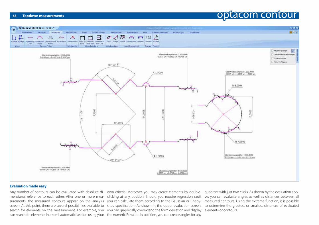
68 Topdown measurements
Any number of contours can be evaluated with absolute di-mensional reference to each other. After one or more mea-surements, the measured contours appear on the analysis screen. At this point, there are several possibilities available to search for elements on the measurement. For example, you can search for elements in a semi-automatic fashion using your
own criteria. Moreover, you may create elements by double-clicking at any position. Should you require regression radii, you can calculate them according to the Gaussian or Cheby-shev speci�cation. As shown in the upper evaluation screen, you can graphically overextend the form deviation and display the numeric Pt value. In addition, you can create angles for any
quadrant with just two clicks. As shown by the evaluation abo-ve, you can evaluate angles as well as distances between all measured contours. Using the extrema function, it is possible to determine the greatest or smallest distances of evaluated elements or contours.
Evaluation made easy

69Topdown evaluation with tolerances
When evaluating serial parts, you have the possibility of indica-ting tolerances. After a fully automatic evaluation through our unique reference run, you can immediately �nd out whether your part is OK or not. The advantage of the element list is in the display of the existing tolerance percentage, in addition to the red-green evaluation. This indicates the exhausted and re-
maining tolerance. This feature prevents unwelcome surprises, as you can immediately see whether you need to counteract the process, thereby avoiding late interventions associated with the usual red-green evaluation. Furthermore, our toleran-ce evaluation allows de�ning intervention limits. These limits are shown in yellow colour when it is time to act. It is possible
to asign a tolerance value to any elements. This works naturally across contours. Simply click on the desired value and type the reference and tolerance value.
Good to know that everything �ts

70 Topdown evaluation with roughness
With our newly developed software algorithms, inexperienced operators are capable to create DIN ISO-compliant measure-ments for the �rst time. Our intelligent algorithms analyse the contour underlying and automatically calculate the proper cut-o� and the compliant cut-o� counts. Just another priceless advantage is the permanent horizontal position of our tracing
arm, which allows roughness measurements on all elements without restrictions to the stylus movement. You may �nd va-rious examples of falling and rising contours and radii in the example above. Needless to say, unrestricted overhead rough-ness evaluations are also supported.
Furthermore, the roughness evaluation is completely integra-ted in the reference run. A further advantage is the possibility of performing di�erent evaluations on one and the same line or radius. In that respect, the ball evaluation above provides an interesting example.
Roughness easy as pie with optacom rough

71Topdown evaluation complete
Our optacom rough and optacom round software modules al-low you to create multiple pro�les. Upon creation, you de�ne uniquely to which norms they should evaluate. These pro�les can then easily be used in our software optacom contour – sim-ply by mouse click. This means that you do not need to adjust any settings when evaluating roughness and roundness. Mo-
reover, all evaluations will be created DIN-compliant and fully automatic. To top this function o�, you not only have a large time-saving, but also the reassuring feeling that possible failu-res cannot happen anymore. In the same easy and trouble-free way in which you create roughness and roundness evaluations, you can obtain form, orientation and position evaluations,
which are already integrated in the optacom contour software module. After having analyzed all required evaluations, you can then focus on printing. Thanks to our print processor, which has an integrated user database as well as customer pro�les, you are able to save your reports as a PDF-document and to send it via email – and this with just a few clicks.
Contour, roughness, roundness, topdown - one software �ts all

72 Roughness in its best shape
4 Signi�cant time savings4 Contour and roughness evaluations in a single measurement run4 No incorrect evaluations because of cut-o� and �ltering automatic4 Due to pro�les, technical knowledge is not needed 4 Several di�erent standards on an single evaluation pro�le
4 Signi�cant cost savings through the use of carbide stylus tips instead of usual diamond stylus tips4 Roughness evaluation on lines, radii and on inclined surfaces; also on topdown and roundness measurements4 Graphical and numerical representation of all reports4 Fully automatic calibration of carbide and diamond stylus tips
4Overhead evaluation of roughness 4 Factory calibration of roughness makes on-site calibration unnecessary4 Roughness automatic facilitates DIN-compliant evaluations4 Roughness evaluation is automatically integrated in reference run
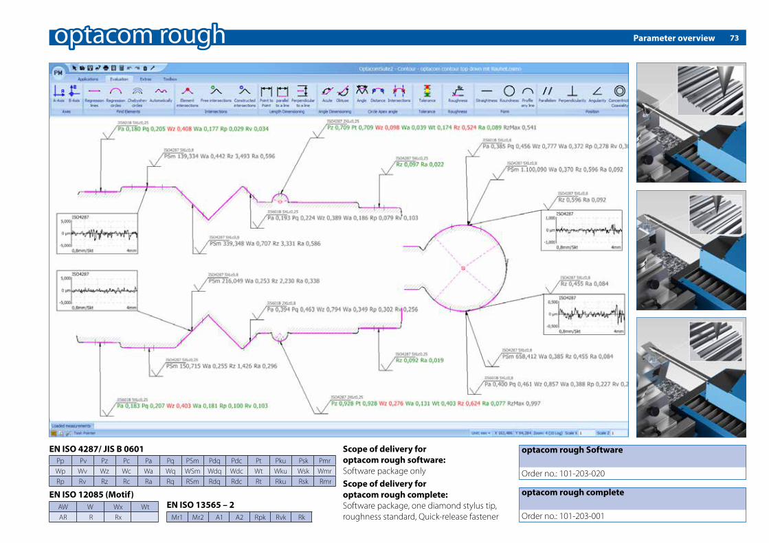
73
optacom rough Software
Order no.: 101-203-020
Scope of delivery foroptacom rough software:Software package only
EN ISO 4287/ JIS B 0601Pp Pv Pz Pc Pa Pq PSm Pdq Pdc Pt Pku Psk PmrWp Wv Wz Wc Wa Wq WSm Wdq Wdc Wt Wku Wsk WmrRp Rv Rz Rc Ra Rq RSm Rdq Rdc Rt Rku Rsk Rmr
EN ISO 12085 (Motif)AW W Wx WtAR R Rx
EN ISO 13565 – 2Mr1 Mr2 A1 A2 Rpk Rvk Rk
optacom rough complete
Order no.: 101-203-001
Scope of delivery foroptacom rough complete:Software package, one diamond stylus tip, roughness standard, Quick-release fastener
Parameter overview
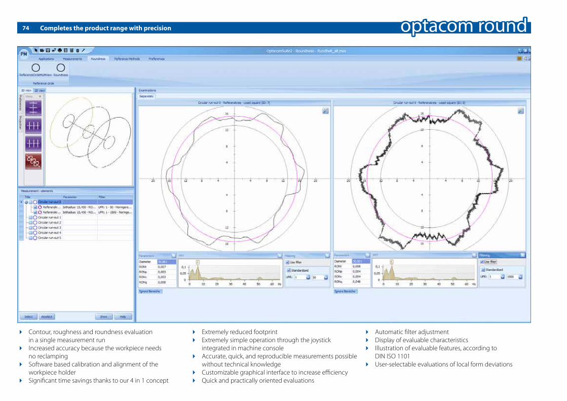
74 Completes the product range with precision
4 Contour, roughness and roundness evaluation in a single measurement run4 Increased accuracy because the workpiece needs no reclamping4 Software based calibration and alignment of the workpiece holder4 Signi�cant time savings thanks to our 4 in 1 concept
4 Extremely reduced footprint4 Extremely simple operation through the joystick integrated in machine console4 Accurate, quick, and reproducible measurements possible without technical knowledge4 Customizable graphical interface to increase e�ciency4Quick and practically oriented evaluations
4 Automatic �lter adjustment4 Display of evaluable characteristics4 Illustration of evaluable features, according to DIN ISO 11014 User-selectable evaluations of local form deviations

75The extension module for roundness measurements
LSCI: Least Square Circle
Regression circle such that the sum of the squares of the local roundness deviations is a mi-nimum
MCCI: Minimum Circumscribed Circle
Smallest circle circumscribing the roundness pro�le
MZCI: Minimum Zone Circle
Two concentric circles enclo-sing the roundness pro�le and having the least radial separa-tion
MICI: Maximum Inscribed Circle
Largest inscribed circle in the roundness pro�le
Filtering method for roundness evaluationFilter de�nition according to DIN EN ISO 11562: Cut-o� numbers: 15, 50, 150, 500, 1500 W/U, arbitrary
Your measuring programme can be perfectly rounded up with our software optacom round and our rotary-swivel table. In this combination it is possible to evaluate and measure contour, roughness and roundness simultaneously (if roughness module optacom rough is installed).
Easy, fast, and comfortable measurements based on a high-precision, program-based operation.
LSCY: Least Square Cylinder
Regression cylinder such that the sum of the squares of the local roundness deviations is a minimum
MCCY: Minimum Circumscribed Cylinder
Cylinder with the smallest possible diameter encompassing the measured cylinder surface
MZCY: Minimum Zone Cylinder
Two concentric cylinder enclosing the round-ness pro�le and having the least radial separation
MICY: Maximum Inscribed Cylinder
Cylinder with the largest possible diameter in-scribed in the measured cylinder surface
Form tolerances:
Straightness
Flatness
Roundness
Cylindricity
Line form
Surface form
without reference speci�cation
Position tolerances
Parallelism
Perpendicularity
Angularity
Coaxiality, Concentricity
Symmetry
Circular run-out
Total run-out
with reference speci�cation
Complete the product range with precisionThe extension module for roundness measurements.

76
Thread Evaluation by optacom
A further analysis option has been added to our well known optacom suite 2, so that additional tasks in production and test laboratories can be performed.
Even complex geometries on workpieces and thread gauges can quickly be assessed at maximum precision, and features for data logging and export are provided.
The user may select between three software con�gurations, according to their particular needs with respect to measure-ments: Light, Standard and Professional.
optacom Thread Software Light
All basic tasks in thread measurement are already o�ered by the Light Version. Even users without particular knowledge may execute thread measurements on workpieces with res-pect to �ank, outer and core diameter, as well as of �ank angle and slope.
A meaningful choice of functions is included to simplify work, like automatic range insulation, this way considerably contri-buting to establish fast and repeatable measuring sequences. Tolerances may be assigned to averages, minimum and maxi-mum limits. Even the smallest edition is able to simultaneously evaluate inner and outer threads.
optacom Thread Software Standard
The standard version has been developed for users examining a large variance of thread types. Additionally to basic thread parameters, further variables are supported, like �ank diameter, single �ank diameter, paired �ank diameter, accumulated slope deviation, partition, conicity, pro�le shape deviation, straight-ness etc., easily to be selected from di�erent thread or factory standards.
The analysis features of the Light version are completed by an optimized window for thread display with enhanced logging possibilities.
Each pass may distinctly be evaluated and presented. All com-mon international standards are supported. Numerous evalua-tion methods, including the usual three-ball method, are provi-ded. Further bene�ts of this software edition are easy handling and a high degree of automation.
optacom Thread Software Professional
Not only threads of workpieces, but also of thread gauges may be assessed at outmost accuracy by means of this software package. For this reason, hardware items developed in-house and intended for safe stretching of ring and plug gauges, are supported.
A software extension for a large quantity of international stan-dards, valid for threaded gauges, is comprised as well, so that users are enabled to perform quick comparison of nominal va-lues and real results.
Detected parameters as well as customized data logging can automatically be exported any time.
optacom Thread Software

77
Function Light Standard Professional
Assessment of basic thread parameters for workpieces ✔ ✔ ✔
Assessment of all thread parameters for workpieces ✔ ✔
Assessment of all thread parameters for gauges ✔
Evaluation by means of three ball method with nominal diameter of measuring wire ✔
Free selection of measuring method ✔ ✔
Free assignment of tolerances, independent of standards ✔ ✔ ✔
Comparison of nominal thread parameters and real results acc. to international standards ✔ ✔
Comparison of nominal thread parameters and real results acc. to international standards (for gauges) ✔
Support for automatic mode (reference run) ✔ ✔ ✔
Support for supplementary thread module of optacom ✔
Automatic range insulation ✔ ✔ ✔
Test possible also for users without particular knowledge ✔ ✔ ✔
Extended display of thread pro�le ✔ ✔
Logging in total view ✔ ✔ ✔
Extended logging (all passes, resp. adaptable) ✔ ✔
Surface optimized for gauge measurement ✔
Quick Start Bar for automatic sequences and evaluations on the basis of measurement programs ✔
optacom Thread Software: Functions o�ered by the distinct versions
optacom Thread Software

78
Type of Thread (Distinguishing Sign) Thread acc. to standards Gauges acc. to standardsMetric thread(M, MF, MJ, UNM, M STI, MJ STI)
ISO 68-1 / ISO 965-1 bis 5 / ISO 1501 / ISO 5855-1DIN 13-1 to 52 / DIN 14 / DIN 2510-2 / DIN 8140ASME 1.13M / ANSI B1.10M / BS 4377 / SAE MA1567
ISO 1502ANSI B1.16M
Cylindrical ISO Pipe Thread ISO 228-1 ISO 228-2
Conical ISO Pipe Thread (R-Rp-Rc, Rp STI, Rc STI) ISO 7-1EN 10226-1, -2
ISO 7-2 / DIN 2999B.S. 21 (A, B)
Round Thread (Rd) DIN 405-1, -2 / DIN 20400 / DIN 405-3
Unity Inch Thread(UNC, UNF, UNEF, UN, UNS, UNRC, UNRF, UNREF, UNR, UNRS, UNJC, UNJF, UNJEF, UNJ, UNJS)
ANSI B1.1 / ANSI B1.15 ANSI B1.2BS 919-1
Whitword Thread (BSW, BSF, Whit.S., Whit., BSW STI, BSF STI, BSP STI)
B.S. 84 BS 919-2
Metric Trapezoid Thread (Tr, ACME, STUB ACME) ISO 2901 / DIN 103-1 to 8 / DIN 380ANSI B1.5 / ANSI B1.8
DIN 103-9ANSI B1.5 / ANSI B1.8
Metric Serrate Thread 33°/ 45° (S), 52° (BUTT) DIN 513-1 to 3 / DIN 20401 / DIN 2781ANSI B1.9 / B.S. 1657
ISO 1502 / DIN 103-9ANSI B1.9
Gas Bottles Conical ISO Thread ISO 11363-1 ISO 11363-2
ANSI Universal Pipe Thread(NPT, NPSC, NPTR, NPSM, NPSL, NPT STI, NPSC STI, ANPT STI))
ANSI B1.20.1SAE AS71051
ANSI B1.20.1SAE AS71051
ANSI Dry-Sealing Pipe Thread (NPTF, PTF-SAE Short, NPSF, NPSI, F-PTF)
ANSI B1.20.3 ANSI B1.20.5
API Thread for Oil Industry(LP, CSG, LCSG, TBG, UPTBG, UPLTBG, IJTBG, BCSG, XCSG, LTC )
API Spec. 5B API Spec. 5B / API Spec. 5B1
ANSI Hose Coupling Thread (NPSH, NH, NHR) ANSI B1.20.7 ANSI B1.20.7
NFPA Hose Coupling Thread for Fire Brigades (NH) NFPA 1963 NFPA 1963
NC Interference Fit Thread Class 5 (NC) (HF/IF; CSF/IF; ONF/INF)
ANSI B1.12 ANSI B1.12
EC Inch Thread (UN STI, UNJ STI, 8 UN STI, 16UN STI) ASME B18.29.1 / ANSI B1.1NASM 33537 / BS 3409
ANSI B1.2BS 919-1
B.A. Thread (BA) B.S. 93 BS 919-2
optacom Thread Software
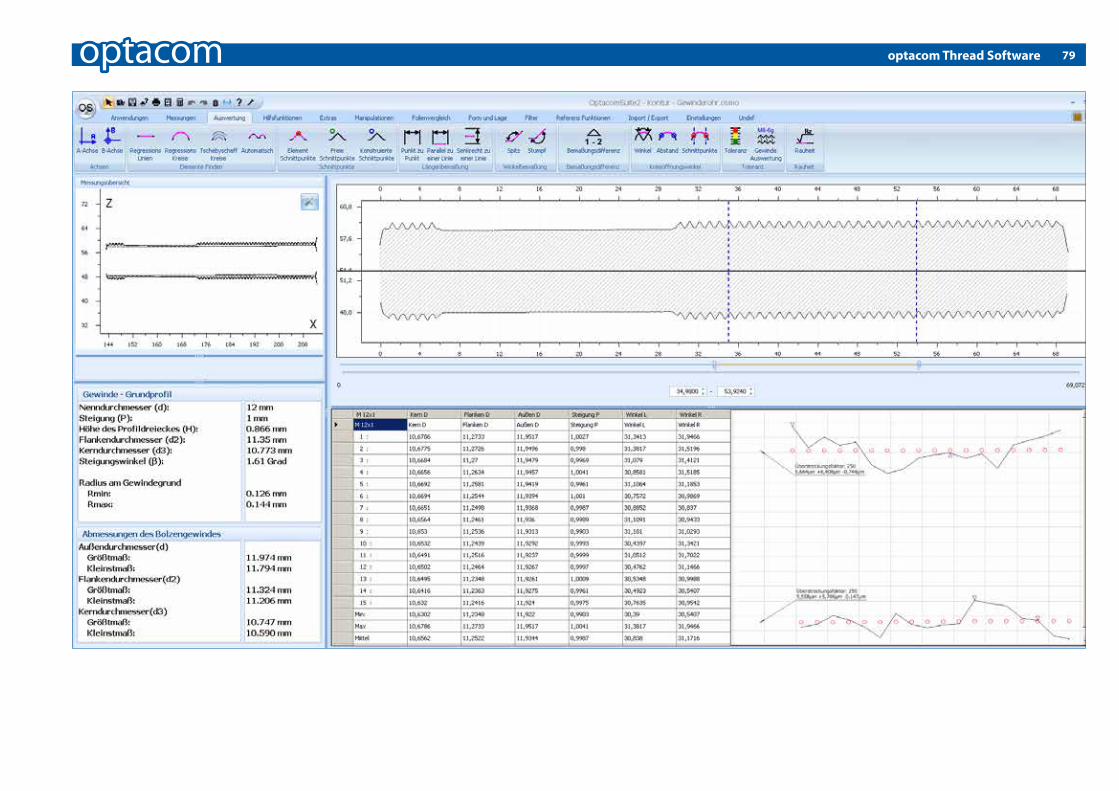
79optacom Thread Software

80
Abbreviation Country Flank Angle German English
ISO 60° Internationale Vereinigung der Standardisierungsgremien International Organization for Standardization
UN USA 60° Amerikanisches Einheitsgewinde mit konstanter Steigung Uni�ed National 8-, 12- and 16 pitch series
UNC USA 60° Amerikanisches Einheitsgewinde, grob Uni�ed National Coarse
UNEF USA 60° Amerikanisches Einheitsgewinde, extra fein Uni�ed National Extra Fine
UNF USA 60° Amerikanisches Einheitsgewinde, fein Uni�ed National Fine
UNJ USA 60° Amerikanisches Einheitsgewinde mit Maßangaben für den Grundradius des Außendurchmessers, vergrößerter Kern-durchmesser des Innengewindes
Uni�ed National thread series with external thread controlled root radius
UNJC USA 60° Amerikanisches Einheitsgewinde, grob, mit Maßangaben für den Grundradius des Außendurchmessers, vergrößerter Kerndurchmesser des Innengewindes
Uni�ed National Coarse thread series with external thread controlled root radius
UNJEF USA 60° Amerikanisches Einheitsgewinde, extrafein, mit Maßangaben für den Grundradius des Außendurchmessers, vergrößerter Kerndurchmesser des Innengewindes
Uni�ed National Extra Fine thread series with external thread controlled root radius
UNJF USA 60° Amerikanisches Einheitsgewinde, fein, mit Maßangaben für den Grundradius des Außendurchmessers, vergrößerter Kerndurchmesser des Innengewindes
Uni�ed National Fine thread series with external thread cont-rolled root radius
UNJS USA 60° Amerikanisches Einheitsgewinde, mit speziellen Durchmes-sern, Steigungen und Einschraublängen, mit Maßangaben für den Grundradius des Außendurchmessers, vergrößerter Kerndurchmesser des Innengewindes
Uni�ed National Special thread series with external thread controlled root radius
UNR USA 60° Amerikanisches Einheitsgewinde mit konstanter Steigung und Maßangaben für den Grundradius
Uni�ed National thread series with external thread controlled root radius
UNRC USA 60° Amerikanisches Einheitsgewinde, grob und Maßangaben für den Grundradius
Uni�ed National Coarse thread series with external thread controlled root radius
UNREF USA 60° Amerikanisches Einheitsgewinde, extrafein und Maßangaben für den Grundradius
Uni�ed National Extra Fine thread series with external thread controlled root radius
UNRF USA 60° Amerikanisches Einheitsgewinde, fein und Maßangaben für den Grundradius
Uni�ed National Fine thread series with external thread cont-rolled root radius
UNRS USA 60° Amerikanisches Einheitsgewinde mit speziellen Durchmes-sern, Steigungen und Einschraublängen und Maßangaben für den Grundradius
Uni�ed National Special thread series with external thread controlled root radius
optacom Thread Software
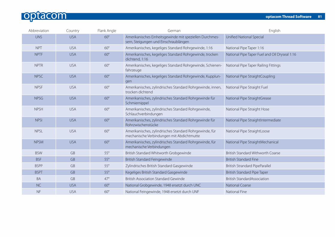
81
Abbreviation Country Flank Angle German English
UNS USA 60° Amerikanisches Einheitsgewinde mit speziellen Durchmes-sern, Steigungen und Einschraublängen
Uni�ed National Special
NPT USA 60° Amerikanisches, kegeliges Standard Rohrgewinde, 1:16 National Pipe Taper 1:16
NPTF USA 60° Amerikanisches, kegeliges Standard Rohrgewinde, trocken dichtend, 1:16
National Pipe Taper Fuel and Oil Dryseal 1:16
NPTR USA 60° Amerikanisches, kegeliges Standard Rohrgewinde, Schienen-fahrzeuge
National Pipe Taper Railing Fittings
NPSC USA 60° Amerikanisches, kegeliges Standard Rohrgewinde, Kupplun-gen
National Pipe StraightCoupling
NPSF USA 60° Amerikanisches, zylindrisches Standard Rohrgewinde, innen, trocken dichtend
National Pipe Straight Fuel
NPSG USA 60° Amerikanisches, zylindrisches Standard Rohrgewinde für Schmiernippel
National Pipe StraightGrease
NPSH USA 60° Amerikanisches, zylindrisches Standard Rohrgewinde, Schlauchverbindungen
National Pipe Straight Hose
NPSI USA 60° Amerikanisches, zylindrisches Standard Rohrgewinde für Rohrzwischenstücke
National Pipe StraightIntermediate
NPSL USA 60° Amerikanisches, zylindrisches Standard Rohrgewinde, für mechanische Verbindungen mit Abdichtmutte
National Pipe StraightLoose
NPSM USA 60° Amerikanisches, zylindrisches Standard Rohrgewinde, für mechanische Verbindungen
National Pipe StraightMechanical
BSW GB 55° British Standard Whitworth Grobgewinde British Standard Withworth Coarse
BSF GB 55° British Standard Feingewinde British Standard Fine
BSPP GB 55° Zylindrisches British Standard Gasgewinde British Strandard PipeParallel
BSPT GB 55° Kegeliges British Standard Gasgewinde British Standard Pipe Taper
BA GB 47° British Association Standard Gewinde British StandardAssociation
NC USA 60° National Grobgewinde, 1948 ersetzt durch UNC National Coarse
NF USA 60° National Feingewinde, 1948 ersetzt durch UNF National Fine
optacom Thread Software

82 The best at last
DIN EN ISO 1101 Geometrical Product Speci�cations (GPS) - Geometrical tolerancing - Tole-rances of form, orientation, location and run-outEN ISO 4287 Geometrical Product Speci�cations (GPS) - Surface texture: Pro�le method -Terms, de�nitions and surface texture parametersEN ISO 4288 Geometrical Product Speci�cations (GPS) - Surface texture: Pro�le method - Ru-les and procedures for the assessment of surface textureEN ISO 12085 Geometrical Product Speci�cations (GPS) - Surface texture: Pro�le method - Motif parameters EN ISO 12562 Geometrical Product Speci�cations (GPS) - Surface texture: Pro�le method - Metrological characteristics of phase correct �ltersEN ISO 13565-1 Geometrical Product Speci�cations (GPS) - Surfaces having strati�ed functio-nal properties-Filtering and general measurement conditionsEN ISO 13565-2 Geometrical Product Speci�cations (GPS) - Surfaces having strati�ed functio-nal properties - Height characterization using the linear material ratio curveJIS B 0601 Surface texture: Pro�le method - Terms, de�nitions and surface texture parameters
Overview of the operation-relevant standards embedded in our software:
500
mm
Measuring range in X
400
300
200
100
0
500
mm
Measuring range in Z
400
300
200
100
0
0,20
μm
Probe arm resolution
0,16
0,12
0,08
0,04
0,18
0,14
0,10
0,06
0,020
optacom Manufacturer x Manufacturer y Manufacturer z
DIN EN ISO 12180-1 Geometrical product speci�cations (GPS) - Cylindricity - Part 1: Vocabulary and parameters of cylindrical formDIN EN ISO 12181-1 Geometrical Product Speci�cations (GPS) -.Roundness - Part 1: Vocabulary and parameters of roundnessDIN EN ISO 12780-1 Geometrical Product Speci�cations (GPS) - Straightness - Part 1: Vocabulary and parameters of straightnessDIN EN ISO 12781-1 Geometrical product speci�cations (GPS) - Flatness - Part 1: Vocabulary and parameters of �atnessVDI / VDE 2631 Sheet 1 Form measurement - Principles for the determination of form and position deviationsVDI / VDE 2631 Sheet 2 Form measurement - Determination of the sensitivity of signal-transmission chainVDI / VDE 2631 Sheet 3 Form measurement - Characteristics and selection of �lters

83Dealers worldwide
The images are not true to scale. Certain images show products with additional equipment.
Technical changes reserved. No liability for errors / printing errors • Rev. 04.2016
BeortekSpain
Taylor HobsonSpain
MetroconseilFrance
BrigelSwiss
Metrology & Quality ServicesEngland
Arnold Instruments Denmark, Finland, Sweden
optacomGermany
Prima BilavcikCzech Republic, Slovenia
PrometSweden
Hanza TarkonEstonia
BaxarPoland
IntratoolRussia
KalibrixMexico
PrimatekItaly
Hommel-TechBrasil
Median L & GHungary
MDMRomania
SC LeadertechRomania
MultisenTurkey
Mehr EngineeringIran, UAE
TrimosIndia
Techno WorldPakistan
DantsinChina
Max ValueThailand
Uni TechSouth Korea, Malaysia,
Thailand, Vietnam

optacom GmbH & Co. KG
4Dürrfelder Straße 18 • D-97508 Obereuerheim4Telephone: +49 (0)9729 90971-0 • Fax: +49 (0)9729 90971-294E-Mail: [email protected] • Internet: www.optacom.com ©
by
koch
-inte
ract
ive.
deM
easu
rem
ent t
echn
olog
y - M
ade
in G
erm
any