Embed Size (px)
Citation preview

NMRA MER 2016Tracks to the Triangle
LCC (Layout Command & Control)
Compiled by: Dick BronsonRR-CirKits, Inc.
Basics of LCC.www.rr-cirkits.com/clinics/MER-2016-LCC.pdf
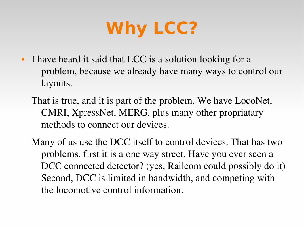
Why LCC?
I have heard it said that LCC is a solution looking for a problem, because we already have many ways to control our layouts.
That is true, and it is part of the problem. We have LocoNet, CMRI, XpressNet, MERG, plus many other propriatary methods to connect our devices.
Many of us use the DCC itself to control devices. That has two problems, first it is a one way street. Have you ever seen a DCC connected detector? (yes, Railcom could possibly do it) Second, DCC is limited in bandwidth, and competing with the locomotive control information.
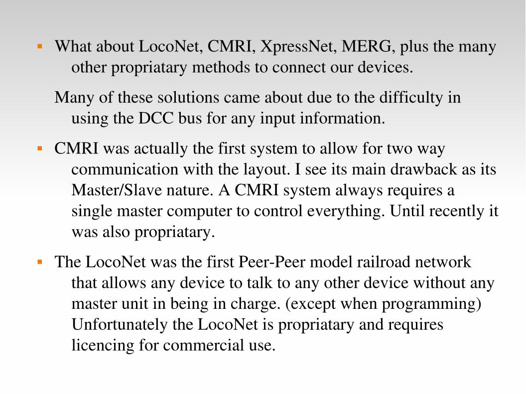
What about LocoNet, CMRI, XpressNet, MERG, plus the many other propriatary methods to connect our devices.
Many of these solutions came about due to the difficulty in using the DCC bus for any input information.
CMRI was actually the first system to allow for two way communication with the layout. I see its main drawback as its Master/Slave nature. A CMRI system always requires a single master computer to control everything. Until recently it was also propriatary.
The LocoNet was the first PeerPeer model railroad network that allows any device to talk to any other device without any master unit in being in charge. (except when programming) Unfortunately the LocoNet is propriatary and requires licencing for commercial use.

The UK based MERG group has many excellent designs, but requires an annual membership fee to access many of them.
The NMRA decided a number of years ago to sponsor an open (license free) common method to interface to your layout. The intent is that, like the DCC standards, many manufacturers will be able to build layout accessory products that will interchange as freely as is now true with mobile decoders.
The bus must use license free commercial standards for its communications as much as is possible. It should be robust and viable into the next generation of electronic products. It should be a peerpeer design with no requirements for any central control. Any two devices from any manufacturers must be able to exchange data.

The result was a set of protocols that can be sent over any media. For example, EtherNet, WiFi, CAN (Control Area Network), and others. (some say tin cans and string, but don’t believe it)
The NMRA calls this LCC. Layout Command and Control. LCC is NOT a replacement for DCC. (unless you consider replacing DCC accessory decoders)
LCC can run along side of DCC, AC, DC, DCS, TMCC, RailPro, Battery power, etc. It is not a way to power your trains, it is a way to control your layout.

Why CAN? It is important to remember that LCC can be transported over many
network technologies.
When we decided to build LCC devices we had to make a choice of which transport to use. Wired Ethernet was one option, but designing a peerpeer network for Ethernet was way above our pay grade. The other problem is that you would require multiport Ethernet Switches with cable connections to each device. This would require more wiring, not less than current options. Wireless has issues with many nodes, and a radio in every node seems like a complex and costly solution as well.
CAN was initially developed as a solution for automotive networking. This means that it is noise tolerant, an industry standard, and designed for the 1224V world. CAN can be operated over a wide speed range, with a linear trade off between bus speed and bus length. The OpenLCB engineers picked a 125Kb rate and 1000’ length as a good compromise for our model railroad use. Also, unlike other PeerPeer systems, CAN can operate at 100% data throughput with error free collision resolution.

Disadvantages. The relatively high CAN bus speed does not allow for free form network designs. A CAN network segment requires a linear bus with a termination at each end. Also due to timing and other electrical limitations a single CAN segment is limited to 40 or fewer physical nodes. There are fairly simple ways to expand a CAN network into multiple segments, so this is not a serious concern.
CAN has several different cabling and connector standards. Some of these use large and costly connectors. Commonly CAN uses the same DB9 connectors used by 9 pin RS232 serial cables. These are still relatively large and no longer so very easy to locate, especially in longer lengths. Another CAN connector option uses the same RJ45 connectors and cables as wired Ethernet does. The OpenLCB engineers opted for RJ45 connectors because of the relatively low cost and their common availability world wide. The 4 pairs of a standard Ethernet cable additionally allow for optional power and other signals in addition to the CAN pair itself.
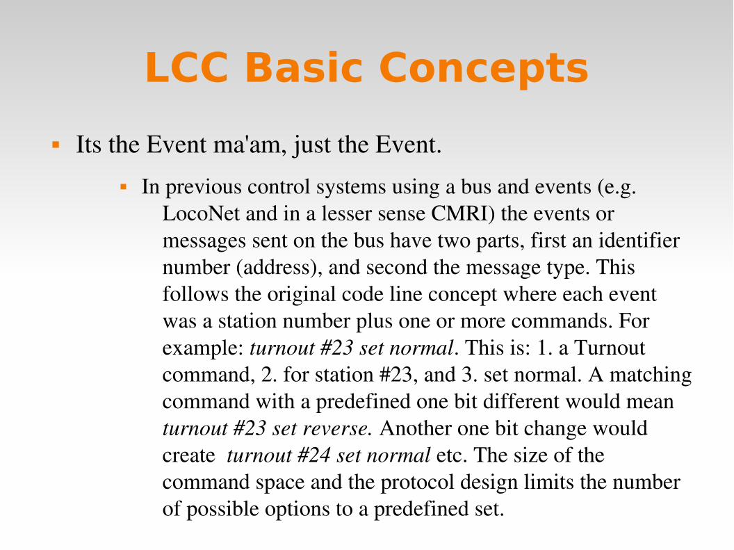
LCC Basic Concepts
Its the Event ma'am, just the Event. In previous control systems using a bus and events (e.g.
LocoNet and in a lesser sense CMRI) the events or messages sent on the bus have two parts, first an identifier number (address), and second the message type. This follows the original code line concept where each event was a station number plus one or more commands. For example: turnout #23 set normal. This is: 1. a Turnout command, 2. for station #23, and 3. set normal. A matching command with a predefined one bit different would mean turnout #23 set reverse. Another one bit change would create turnout #24 set normal etc. The size of the command space and the protocol design limits the number of possible options to a predefined set.

For example turnouts only have two options, normal and reverse. If you have a three way turnout, (very rare on the prototype) sorry, you need to think of it as 2 two position turnouts. Have a three color signal, sorry, you need to think of that as either three different on, off, messages, (CMRI) or else combine two 2 position messages. (LocoNet)
In the LCC world an event has no predefined meanings. None, Keiner, Nada! An LCC event simply says; ’something has happened’, or ’something should happen.’ How it is defined is 100% up to you, the user. In our previous example it could still mean turnout #23 set normal. However with LCC 'turnout #23' is just what you call it on your layout, not that it was pin 23 on some brand of hardware controller. Set normal just means that the event moves the turnout to normal. Undoubtedly you will want another event to move the turnout back, however that will be a completely different event.

Maybe you want all turnouts to move to normal when you first start up. With our conventional control bus you need some way to send the proper commands to each turnout. With the LCC system you could simply define a new Event that says 'all turnouts normal' and then configure each turnout to also respond to that command (by moving in the appropriate direction)
Producer Consumer You will probably hear LCC folks throwing around terms like Producer and Consumer. They aren't talking about a big business takeover. They are trying to sound educated. <G> Producer simply means that some device can create (produce) an Event. Some examples might be a push button or block detector. Consumer just means that some device can respond to (consume) an Event. It could be a lamp, a turnout driver, or anything else that you can control. Events can have from 1 to many Producers. Events can have from 0 to many Consumers.http://openlcb.org/trunk/documents/notes/ProducerConsumerModel.html

To elaborate a little bit. For an event to happen something must have sent it. Therefor there has to be at least one producer. In the LCC world it is possible for many different Producers to create the same event. For example you might want to have turnout control buttons track side and on a remote panel. Thus the statement that every Event has one or more producers.
For consumers the picture is a bit different. There is nothing in the specification that says any device has to respond to an Event. You may have built a panel for a passing siding that doesn't yet exist. If you press its turnout control button an Event message gets sent out. (producer) However there is nothing to respond. (consumer) Later you might add a turnout controller and a computer based CTC machine and have several consumers for that Event. Thus the statement that every Event has zero or more consumers.

LCC driving Signals
Application to SignalsSignaling usually requires more logic than can be handled via raw Events, e.g. occupancy, turnout position, look ahead to the next signals, etc. However a signal controller could be designed to listen to all of the appropriate Events and fully control the signal aspects. Note that it's still useful for a signal system to emit (produce) Events for each aspect change so that e.g. a control panel can mirror the appearance of the onlayout signals, or so that the next signal can know its aspect.
In the following examples we will compare different methods of controlling signals. This varies from individual LEDs to a full blown track side control point.

Signals via individual lamp driversYou can connect the lamps of a signal head to individual Consumers:
This is a powerful but complicated approach. It requires that the controller individually turn each lamp on or off. This can cause excessive control traffic and potentially poor timing of flashing signals. This is the method used by CMRI and currently (as of October 2016) available LCC equipment.

Signals via individual head driversYou can also control signals with Events for the specific colors or functions
of a single head.
This method requires less command traffic than the previous one. However, if the controller does not know how to flash the signals, it may still result in constant streams of messages to be able to show flashing aspects. The Digitrax SE8c falls into this category. It normally only displays Green, Yellow, Red, and Dark. To show ’Flash Y’ you need to alternate between sending Yellow and sending Dark. Got Lunar? Nope!

Signals via aspect driversYou can control an entire signal mast with just one Event for each high
level aspect of the signaling system.
This method requires the minimum amount of command traffic to control the signals themselves. However it still requires an external controller or a program such as JMRI to monitor the layout and calculate the proper aspects. Our RRCirKits SignalMan in NMRA Signal Aspect mode falls into this category.

Signals via control point driversYou could also control an entire interlocking with just single Events for
each highlevel aspect of the signaling system including turnout position.
This method is similar to the signal aspect driver, but includes turnout control and possibly even occupancy detection on the same node. However it still requires an external controller or program such as JMRI to calculate the proper aspects. The RRCirKits LNCP is similar to this option.

Integrated SignalsIn each of the examples above, the signal controller uses (consumes) Events that
directly control the appearances of the signals.
It's also possible to build a signal controller that watches all related status Events from the railroad and CTC panel and makes independent decisions about the proper signal states and appearances. This type of controller would control its signals without any external computer involvement.

LCC BackgroundAt the Detroit NMRA National back in 2007 the NMRA was seeking a network standard to be known as NMRAnet for layout control. They proposed that the Manufacturers Working Group create a standard in a 6 month time frame. (if my memory serves me correctly)
LCC grew out of a concept first presented by John SochaLeialoha during a lunch meeting in the food court following that meeting. John proposed that the PC (Producer Consumer) model be used by this new standard, and proceeded to try to explain to some of us gathered around the table just what he meant by that. Time and politics passed, and the NMRA tentatively accepted one early proposal. However, other folks didn’t agree and formed an independent project known as…
More time and politics passed, and the NMRA finally decided to get out of the specification writing morass, and turned that job over to the original OpenLCB group.

Fast forward to just prior to the Cleveland NMRA National in 2014. The NMRA went back to the OpenLCB group and gave them an ultimatum. Present a proposal to the NMRA or they would declare the project as dead. This created a new sense of urgency and the basic specifications were presented to the NMRA in time for the early 2015 board meetings. Unfortunately in the rush to publish something, some key features were omitted, so it was late 2015 before we (RRCirKits, Inc.) felt that the specifications were mature enough to actually start delivering hardware. Specificly we wanted our users to have an approved method for upgrading their products.
With the NMRA aproval came their new branded version of the OpenLCB specifications. They call it LCC. (Layout Command and Control)
Early Hardware
One of the first manufacturers of CAN based layout control nodes was the MERG group. They proposed that the NMRA accept their protocol. In fact some of the early development work was done using their hardware.
Another early proposal came from Don Voss. (brother of Di Voss) It was Don’s proposal that was originaly entertained by the NMRA as the NMRAnet.
As I previously mentioned, the OpenLCB group felt that these protocols were too restrictive to be chosen as the next generation standard, so they pushed forward with their own ideas and protocol proposals.
Fortunately there were some in the NMRA that were taking notice.

One of the first manufacturers of OpenLCB nodes was Tim Hatch of TCH Technologies. A couple of Tims products are shown here.
These early boards were essentially OpenLCB replacements for the 32 line Bruce Chubb input and output boards. They were developed as a way for the developers to run real hardware to prove out the specifications. Unfortunately they have the same limitations as their CMRI equivilents in that they are strictly input or output slaves to a computer program. These boards are no longer available nor supported by recent JMRI versions.
TCH also manufactured the first CAN bus to USB interface available for the OpenLCB.

Another early hardware developer was Don Goodman of Railstars. His OpenLCB board includes both inputs and outputs. It is called Io. (named for the Jovian moon) http://railstars.com/hardware/io/io/
As far as I know the Railstars Io board is still available. However, like the TCH boards, the Io supports just two producers or consumers per line, so it is essentially an I/O board tied to a computer program.

Configuration of LCC nodes
One of the key new concepts in the LCC protocol is that, not only the configuration, but the ’decoder file’ (in JMRI terms) itself should reside in the LCC node. This is an important change from the status quo.
Originally hardware had a fixed purpose. Each required its own dedicated connections. Lionel crossing gates flashed with contacts.
Then some devices were connected to a bus. (or track) This required assigning addresses or channels. The usual solution for addressing was to include a set of jumpers or switches for the selection. In some cases it was a plug with different component values.
As electronics improved the selection of addresses was moved into the device code itself. An example that we are all familiar with is modern DCC mobile decoders.

One of downsides of this new method is that our decoders now need to be configured with a new (not default) address. That itself was automated by some manufacturers, but it soon became evident that something more was needed than simple interactions through a hand held throttle. Some new decoders currently have 1000 or more values to configure.
JMRI and other programs have come to the rescue, but the decoders are now so complex that a ’decoder file’ is required for each locomotive and stored on a computer to help keep track of changes. The DCC specification does not include an easy way to read information from a decoder except very laboriously and slowly on a special connection. (called a programming track)

This was deemed to be too slow and inflexible for the new LCC equipment. Two key changes were required. The first was that any LCC node could be configured in place on the layout at any time with no need to access it for jumper changes or button presses. The second was that any information required to configure a node should reside in the node itself, and be available to any configuration tool connected to the network. Now any node could be configured in one place and moved to another with all the information moving with the node itself. This means not only configuration values but user names as well.
Another key design choice was that the manufacturer would assign a node ID during manufacturing in a manner that prevents any duplication of addresses…. ever, anywhere! (similar to Ethernet MAC addresses)

Currently Available LCC Hardware
We at RRCirKits watched all the above history unfold, and when we figured that the gyrations were settling down, and the smoke was mostly cleared, we started the design cycle on a family of CAN based OpenLCB boards. The NMRA then branded these as LCC. This initial development process was delayed due to a missing firmware upload protocol, but we finally started shipping hardware to our first customers this past January. (a year after the NMRA accepted the current protocol)
Our present product line includes just the basic items required to start investigating the new LCC bus. We chose our first node to be compatible with our existing product line of I/O daughter cards. This allows the user to do basic train detection, turnout control, and similar functions using existing hardware options.

Power – The LCC CAN bus has two basic options for power supply to the nodes. The first is to supply power to each node. The second is to power the node from the CAN bus cable. Of course a node can also do both. (some early hardware did that) Because one of the desirable features of the LCC is to eliminate as much layout wiring as is practical, we chose the second option. We suggest that the user supply power to the bus as required by using our PowerPoint module and/or our LCC Repeater module.
Termination – The LCC bus is much faster than existing layout control busses, so it requires termination at both ends for proper response. The standard allows this termination to be part of each board, using jumpers or switch selection, or to be seperately provided. We chose the latter option because we feel that it is less likely to be configured incorrectly. The only place that the terminators may be easily connected are at each end of a bus segment, just where they are required, and no place else.

Cables – The CAN version of LCC was specified to use the commonly available CAT5, CAT5E, and CAT6 cables with RJ45 connectors. The industry standard for CAN over CAT5 was chosen. This was done so that the user could easily purchase or else construct his own cables. The 6 conductor silver satin cables used by some other manufacturers are no longer as easy to find as they were 20 years ago. The two different systems (CAN and Ethernet) that use these cables supposedly will not suffer damage if the cables are cross connected accidentally between networks. Of course neither network will work in that case. With the recent addition of an option to place the DCC rail sync information on an otherwise unused pair, CAN can now support smart boosters.
I have referred to the CAN version of LCC. The LCC protocol is capable of being used over different systems, CAN, Ethernet, and WiFi being just a few common ones already in use. Our existing RRCirKits hardware uses the CAN bus version.
Nodes – The LCC is nothing but a piece of cable without nodes to actually connect into your layout. The selection of a ’first’ node to design and build was actually quite simple. We have a whole series of I/O modules that do block detection, stall motor driving, signals, solonoids, optical isolation, etc. Our first LCC node, called the TowerLCC is simply two 8 bit ports that can connect to any of these I/O modules using short ribbon cable jumpers.
The next node we designed was a Signal Driver. It is not yet available because I have not figured out how the user should best configure it.

The Future of LCC
Smart Detector, Railcom, Circuit Breaker, Reversers
Simple Detector, CT coil based.
Stall Motor Driver (Support for ganged Tortoises, MP1, etc.)
Dual Coil Solenoid Driver.
LocoNet to LCC Gateway. (LCC support for existing products)
Ethernet Links.
Wireless Links.
Throttles
Smart Boosters, Command Stations.

LCC Configuration Tools
Because all the configuration information as well as the values and user names reside permanently in the nodes themselves, it is easy to use different configuration tools interchangeably. There is no need to synchronize them externally or move files around.
This information is stored in the node as a CDI file. (Configuration Description Information) The CDI is in .xml format, but because it references internal register locations it is not advisable to attempt making any changes manually.
Example CDI info as stored in a node: <?xml version='1.0'?><cdi xmlns:xsi='http://www.w3.org/2001/XMLSchemainstance' xsi:noNamespaceSchemaLocation= 'http://openlcb.org/schema/cdi/1/1/cdi.xsd'><identification><manufacturer>RRCirKits</manufacturer><model>SignalLCC</model> <hardwareVersion>revA</hardwareVersion><softwareVersion>B1</softwareVersion></identification><segment space='253'>

The original CDI tool was created as a part of JMRI. www.jmri.org
Select OpenLCB and choose ’Configure Nodes’
Next open the node you need to configure.
Open ’Supported Protocols’.
Then choose ’CDI’ to open theJMRI CDI tool and read the node.

This will open the JMRI CDI tool window and allow you to read and write data to the node. The window header shows the node ID that is open and the Identification shows some basic data about the node.
The actual data will not show up unless you choose to ’Read’ it from the node. If you make any changes to the information, then you must ’Write’ the data to store it into the node.
There is a ’Read All’ button at the bottom of the window, but be forwarned, it takes a lot of time to read all of the data in.

Because LCC is an open standard anyone can develop tools for it. One such developer is Robert Heller of Deepwoods Software. This is part of his model railroad software package. http://www.deepsoft.com/home/products/modelrailroadsystem/downloadmr/Run the OpenLCB tool.
If you are using the LCC BufferUSB as your interface device, then select ’Grid Connect CAN over USB’ .
Next select the proper COM port. (this example is on Linux)
Once you click on ’Open’ a similar window to the one you saw in JMRI will open. The first entry is the program connection itself. The other entries are a list of the attached nodes.
As in JMRI, open the node you need to configure by expanding its tree view.

Robert’s CDI tool opens a bit differently than JMRI. You need to drill down in the tree to see more information.
However, because the information actually is stored in the node, you should see the same data.
The CDI tool is started by clicking on ’CDI’ just as it was in JMRI. However, If you missed the LCC traffic indicators, there is no visual feedback that anything has happened, and it takes a long time before the CDI window loads and finally opens. Resist the temptation to click it again.

Be patient and you will be awarded with a much more usable presentation. (In my opinion)
Again the Node ID is found at the top of the window.
Node Identification follows.
Next is any Name and Description that you have given to the node. (be sure to click on ’Read’ to see it.
The key difference is that the data is presented in a tab selected format. Note: the JMRI developers are working on a similar improvement.
In this example we have selected ’CHANNELS’ and ’Channel 1’.
In like manner, any repeated similar items are presented as tab choices.
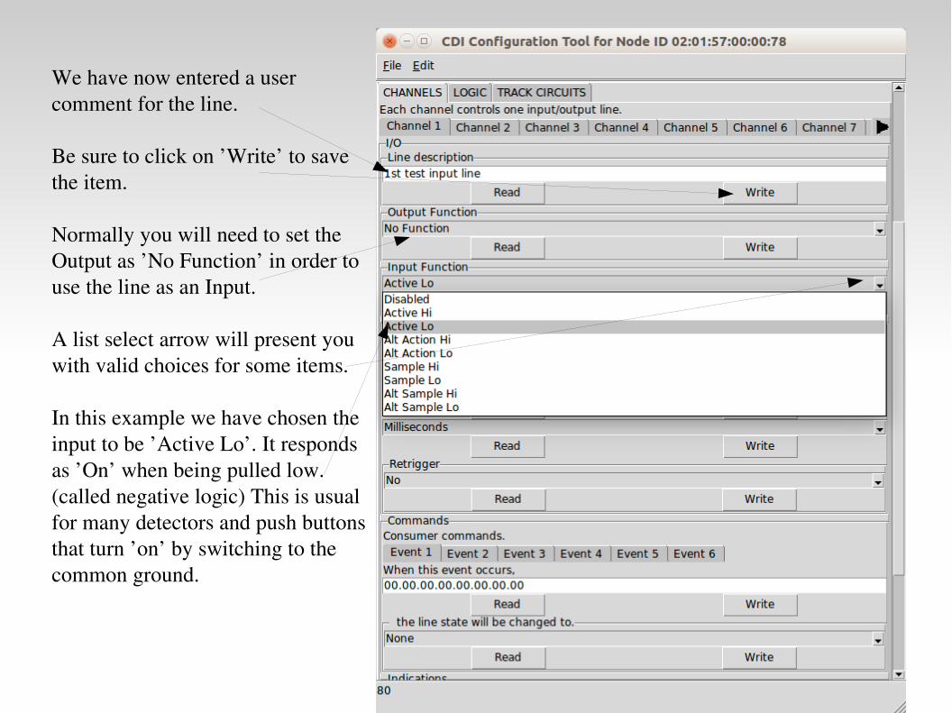
We have now entered a user comment for the line.
Be sure to click on ’Write’ to save the item.
Normally you will need to set the Output as ’No Function’ in order to use the line as an Input.
A list select arrow will present you with valid choices for some items.
In this example we have chosen the input to be ’Active Lo’. It responds as ’On’ when being pulled low. (called negative logic) This is usual for many detectors and push buttons that turn ’on’ by switching to the common ground.

An input line is used to ’Produce’ messages, so scroll down to the ’Indications’ section and pick the first Event.
Select when the event is sent. For this first event it will when the input is ’On’. (low per our initial setting)
For the event number you can either copy an event into the box from someplace else, or else click on ’Read’ to get a new event.
Now select ’Event 2’ and enter the data for the ’Input Off’ event.
For simple setups the remaining events will be unused. Our button or detector or whatever is connected to the line will now send 02.01.57.00.00.78.00.06 when pressed (on) and 02.01.57.00.00.78.00.07 when released. (off)

In like manner outputs (Consumers) may be configured to respond to events. These Events may come from a JMRI program, other inputs, or even logic statements.
Current configuration tools are still under development. One design target is to eliminate any reference to the actual EventID numbers, and simply use the users own names for items.
I am not optimistic about seeing that in my lifetime, but once a line is configured you really can ignore the details of each EventID because you will not need to worry about any duplication, and you do not need to know them ahead of time to properly select the hardware like you do on existing networks. In LCC the hardware either offers you a new unused Event, or you may configure it to respond to your own already defined Events. (just copy your EventID to it)

Other Layout Animation Signaling is normally the most complex animation applied to a model
railroad layout.
Crossing gates and flashers with or without sound is another closely related animation that is often attempted by modelers. Commercial gate animators have various levels of sophistication, from simple on – off, control to reasonably accurate operation. I have seen designers twist themselves into knots trying to figure out how to do it accurately in both directions. However if you think in terms of Events it is actually very simple. Define two blocks. The first covers the entire gate Approach area. The second covers just the highway portion. We call it the Island.The Logic:1. Approach clear AND Island clear = gates up (requires memory of the two events plus AND logic)2. Approach occupied event = gates down3. Island occupied event = gates down4. Island clear event = gates up

Traffic signals. Simple flashers to full four or six cycle control.
Building lighting and signage.
Day – Night lighting.
Street and parking lot lighting.
Operating bridge spans.
Warehouse doors.
Mine skips.
All of the above could be individual devices, or centrally controlled for even more realism. Building lights could follow room lighting, bright in the evening, off late at night, then on again early in the morning. Traffic signals go to flashing mode late at night. Warehouse doors open when trains arrive. Etc.

Questions
?