Embed Size (px)
Citation preview
© 2021 JETIR July 2021, Volume 8, Issue 7 www.jetir.org (ISSN-2349-5162)
JETIR2107088 Journal of Emerging Technologies and Innovative Research (JETIR) www.jetir.org a680
COMPARITIVE ANALYSIS OF RCC BUILDING
WITHOUT OUTRIGGER AND WITH
OUTRIGGER AND DIAGRID SYSTEM
Shreem Sharma1 , Prof. Satyendra Dubey2,
1Student,2 Assistant Professor,
1,2 Civil Engineering Department,
GYAN GANGA INSTITUTE OF TECHNOLOGY & SCIENCES, JABALPUR, MP
Abstract : The development of high strength construction materials, technology, structural systems and analytical methods
for modelling, analysis and design enabled the emergence of high-rise buildings. High rise buildings are subjected to wind
load and seismic load .But as their height increases, lateral loads are induced by wind forces and earthquake forces which
are resisted by shear walls. Now a days diagrids and outriggers are in use. These provide structural stability which
ultimately minimizes structural damages. Outrigeers mainly decreases stiffness which are caused by lateral loads. The
outriggers join the core to exterior columns which reduces drift in the building due to lateral loads. Diagrids are inclined
on exterior surface of structure of the building which helps in resisting lateral loads due to axial action of diagonals. The
analysis of 11 story building with outrigger and diagrids is to be analysed using ETABS 2019. A regular floor plan of
16mx16m is considered and structural elements are designed as per IS code 456:2000 and IS code 800:2007.A comparative
analysis of RCC braced frame structure and a building with outriggers and diagrid will be done. A comparison will be
based on the parameters like base reactions, displacement, moment and shear. The results will be studied, plotted through
graphs and tabulated in the following chapters.
Keywords: Structural Analysis, forces, deflection, lateral forces, Etabs
I. INTRODUCTION
From the ancient times till now, the human race has always been intrigued by height, and we have always aspired to strive for the stars.
Today, there is a shown competition in the human race to claim ownership of the world's tallest skyscraper. Tall buildings first
appeared in the United States of America in the late nineteenth century. They made up the so called "American Building Type," which
means that the majority of the world's tallest structures were constructed in the United States. However, there is currently a global
architectural phenomenon in the creation of tall structures that has progressed quickly in recent years. Since, the metropolitan
population grows the amount of area available for housing decreases. Because of the growth in work opportunities, people from rural
regions are relocating to cities on a daily basis. As a result, cities become more densely inhabited, and the cost of land rises, leading to
the usage of multi-story buildings. As a result, multi-storey structures are the most prominent and efficient answer to these issues. For
designing we should consider all the factors.
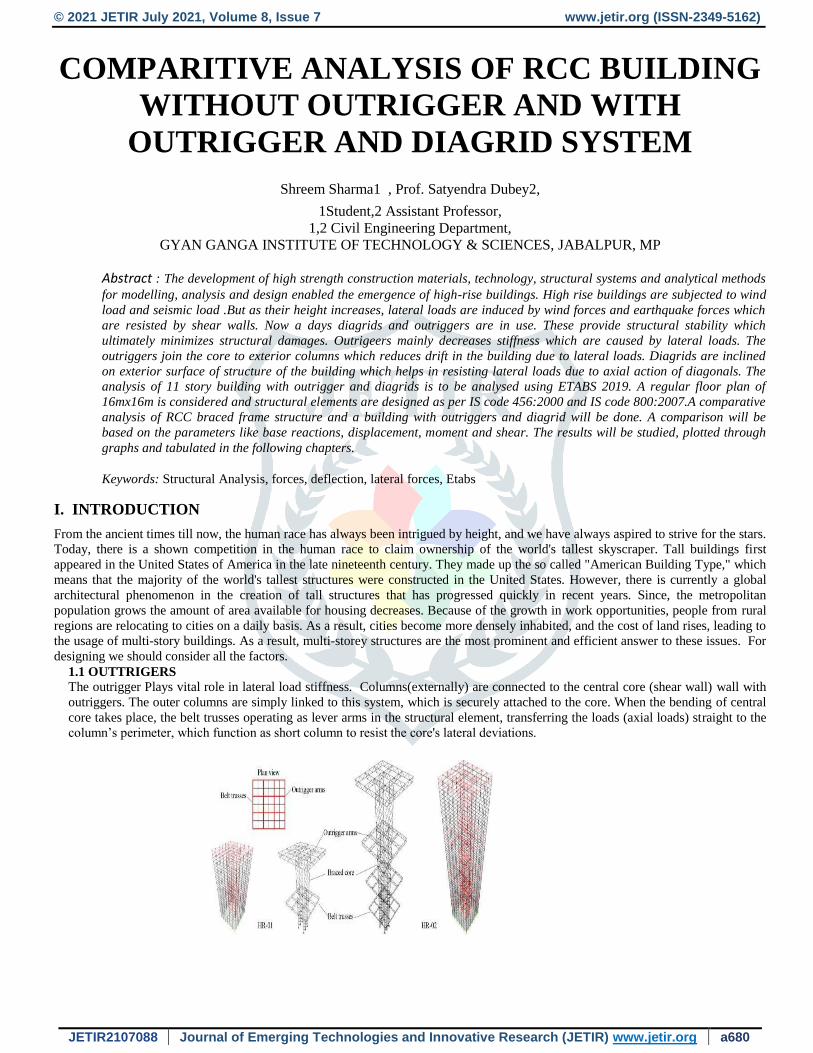
1.1 OUTTRIGERS
The outrigger Plays vital role in lateral load stiffness. Columns(externally) are connected to the central core (shear wall) wall with
outriggers. The outer columns are simply linked to this system, which is securely attached to the core. When the bending of central
core takes place, the belt trusses operating as lever arms in the structural element, transferring the loads (axial loads) straight to the
column’s perimeter, which function as short column to resist the core's lateral deviations.
© 2021 JETIR July 2021, Volume 8, Issue 7 www.jetir.org (ISSN-2349-5162)
JETIR2107088 Journal of Emerging Technologies and Innovative Research (JETIR) www.jetir.org a681
II. ANALYSIS: STATIC AND DYNAMIC
Response spectrum analysis for dynamic analysis
RS is a linear dynamic analysis. Response spectrum(RS) is a graph between maximum responses versus time period in the ground
level conditions. It is obtained from “time history” analysis for ground motion. On considering condition by taking into account of the
values (maximum) response for every single time period in the RS analysis. The response spectrum method (RSM) was first came into
effect in 1932 by Anthony Biot at Caltech.
OBJECTIVE OF THE STUDY
Outriggers provide stable design criteria, design recommendations for high rise unstable structures. This thesis has following
objectives for serving the engineering profession-:
Outrigger bracing systems enables designers to be better prepared for determining outriggers applicability in seismic zone.
Diagrids provide strength and stiffness to large span and high-rise buildings where these have complex geometrics and curved
shapes.
By using outrigger framed systems, diagrids in the building lateral load resisting capacity are increased of high-rise buildings.
III. LITERATURE REVIEW
1. ANALYSIS OF A HIGH RISE BUILDING FRAME CONSIDERING LATERAL LOAD
RESISTING MEMBERS: A REVIEW,2021 Mohit Kumar Prajapati
Tall buildings are subjected to seismic loads and wind loads which stimulates lateral deflections in the building. The resistance to the
horizontal forces is essential for detailing of structural systems. The efforts of structural engineers have made possible to keep raising
the height of the building and keeping the deflections within the permissible limits and restricting the proportion of the materials. In
this paper a research on the efficiency of the framework is seen that is whether the outrigger framework with centre shear divider and
hex lattice frameworks, is able to transfer the horizontal loads evenly to the ground. The end communicated that the hexagrid system is
best as it has least sidelong expulsion and it gives a better designing appearance than the construction.
2. COMPREHENSIVE ANALYSIS OF OUTRIGGER BUILDING SYSTEM 2020, THEJAS H
K,Laxmi S,Abhilash D T
Outriggers and their structural composition are briefly understood by this paper. The lateral deflections and base moment are
significantly reduced by usage of outriggers as they reduce the rotation of the core as compared to free core without outrigger. A
number of studies has been carried out in past 20 years on analysis and design of outriggers. The comparison of core building without
outrigger, single outriggers and double outriggers., The lateral displacements for single outriggers, is observed to be reduction of
68.51%. The storey shear for single outriggers 60.71%. In case of double outriggers system, the lateral displacements are observed to
be having a maximum reduction of 87.49% and in case of storey shear it is expected to be 80.81%.
3. DESIGN AND ANALYSIS OF CORE AND OUTRIGGER STRUCTURAL SYSTEM 2020,
Krutagn Patel, Prof. Vishal Kumar Patel, Dr. Snehal Mevada
This article discusses the use of ETABS software to design Core and Outrigger structural systems, RCC core and steel structure,
seismic analysis and comparison with normal moment resisting framed RCC buildings, and cost efficiency analysis against framed
RCC buildings. More pressures are attracted to the centre of the building and less to the outside perimeter of the building when core
and outrigger structures are used, which has proved to be excellent for seismic resistance. The value of overturning moments shows
that the Core and Outrigger buildings encounter less moment at the base than the RCC building. The inner core is heavy and the
outside structure is light because of the core and outrigger construction. In terms of Forces, Moment, Deflection, and Cost, it
determines the structural stability under lateral forces. As a result, in compared to an RCC construction, ultimate base shear at the base
is relatively low.
IV. METHODOLOGY AND ITS CONSIDERATION
The modelling and analysis of a Outrigger diagrid structural model is carried out using Etabs software. the sizes of structural
members, geometric parameters and load consideration of both the structural. The dead load (875-1987, part-i), live load (875-1987,
part-ii), earth quake (18932002, part-i) and wind load (875-1987, part-iii) and all load combinations are applied to the all models. The
characteristics compressive strength of concrete is taken as 25 N/mm2. the yield strength of main reinforcement is taken as 415
N/mm2.

© 2021 JETIR July 2021, Volume 8, Issue 7 www.jetir.org (ISSN-2349-5162)
JETIR2107088 Journal of Emerging Technologies and Innovative Research (JETIR) www.jetir.org a682
SPECIFICATIONS OF BUILDING’S MODEL
Specifications Data
Storey Height 3.0 m
Base Storey Height 3.0 m
Number Of Bays along X-Direction 6
Number Of Bays along Y-Direction 6
Bay’s Length along X-Direction 3.2 m
Bay’s Length along Y-Direction 3.2 m
Concrete Grade 25
Density of Reinforced cement
concrete
25 kN/m3
Density of Wall Masonry 20 kN/m3
Density of mild steel 76.97 kN/m3
Regular Column dimensions 300 mm x 600 mm
Beam dimensions 300 mm x 450 mm
Live Load
Dead Load
Super dead Load
3 kN/m3
1 kN/m3
6 kN/m3
Soil Conditions Medium
Damping Ratio 5%
Poisson Ratio 0.2
Response Reduction Factor(R) 5
Importance Factor 1.5
Seismic Zone Zone4
Table: SPECIFICATIONS OF BUILDING’S MODEL
a) OUTTRIGER PLACINGS
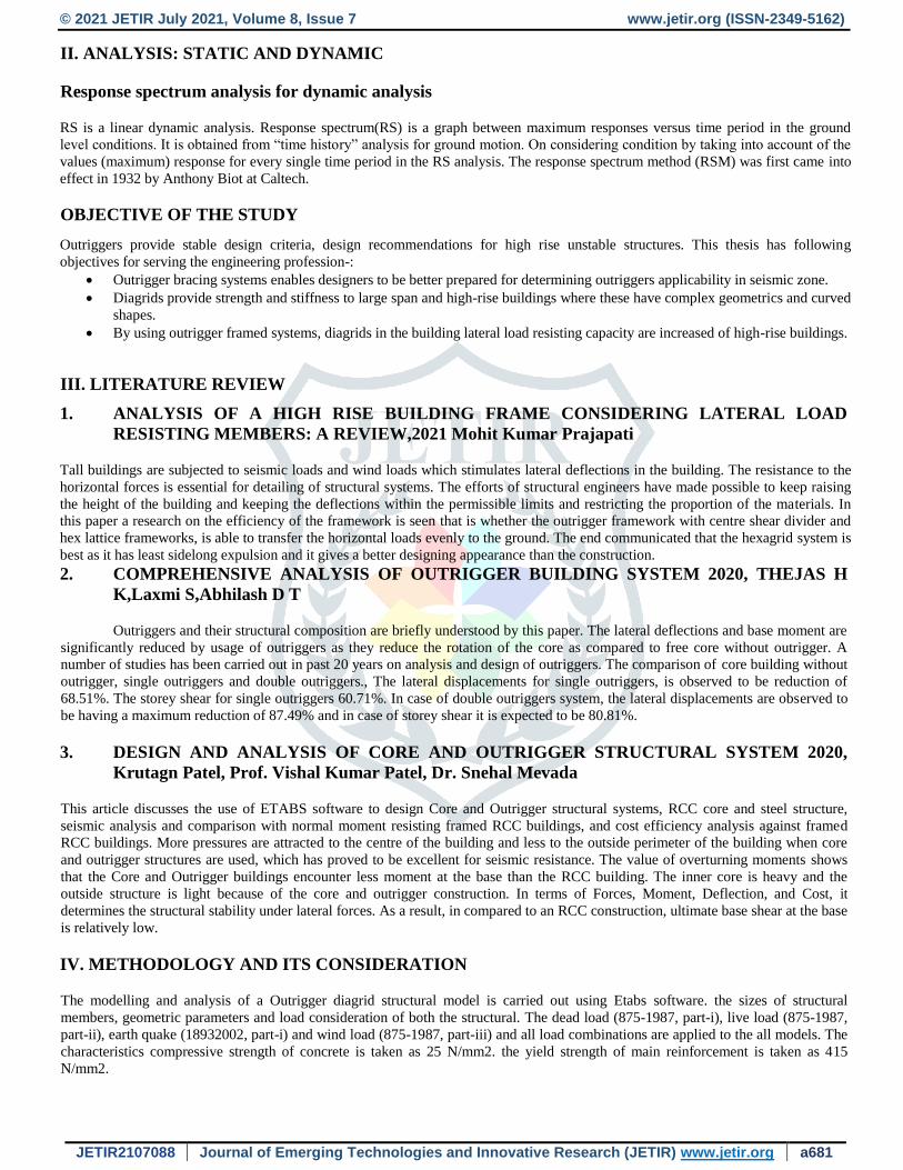
Fig: PLACING OF COLUMN, BEAM, SLAB AND OUTRIGGER WALL
© 2021 JETIR July 2021, Volume 8, Issue 7 www.jetir.org (ISSN-2349-5162)
JETIR2107088 Journal of Emerging Technologies and Innovative Research (JETIR) www.jetir.org a683
Fig: PLACING OF COLUMN, BEAM, SLAB AND OUTRIGGER WALL
V. RESULT AND DISCUSSION
Static and dynamic analysis has been followed by response spectrum method by ETABS software in terms of Maximum Base
Reactions, Maximum Story Displacement in X and Y.
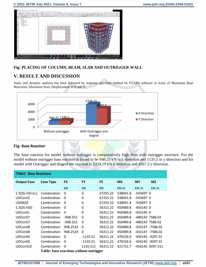
Fig: Base Reaction
Fig: Base Reaction
The base reaction for model without outrigger is comparatively high than with outrigger structure. For the
model without outrigger bass reaction is found to be 948.25 kN in x direction and 1135.5 in y direction and for
model with Outrigger and diagrid the reaction is 5334.19 kN x direction and 4267.3 y direction.
TABLE: Base Reactions
Output Case Case Type FX FY FZ MX MY MZ
kN kN kN kN-m kN-m kN-m
1.5(DL+SD+LL) Combination 0 0 67255.22 538041.8 -543697 0 UDConS2 Combination 0 0 67255.22 538041.8 -543697 0
UDSlbS2 Combination 0 0 67255.22 538041.8 -543697 0
1.5(DL+SD) Combination 0 0 56311.22 450489.8 -456145 0
UDConS1 Combination 0 0 56311.22 450489.8 -456145 0
UDConS7 Combination -948.252 0 56311.22 450489.8 -480143 7586.02
UDConS7 Combination -948.252 0 56311.22 450489.8 -480143 7586.02
UDConS8 Combination 948.2524 0 56311.22 450489.8 -432147 -7586.02
UDConS8 Combination 948.2524 0 56311.22 450489.8 -432147 -7586.02
UDConS9 Combination 0 -1135.51 56311.22 479226.9 -456145 -9297.31
UDConS9 Combination 0 -1135.51 56311.22 479226.9 -456145 -9297.31
UDConS10 Combination 0 1135.511 56311.22 421752.7 -456145 9297.311 Table: base reactions without outrigger
0
2000
4000
6000
Without outtrigger With Outtrigger anddiagrid
948.25
5334.19
1135.5
4267.3
X Direcition
Y Direction
© 2021 JETIR July 2021, Volume 8, Issue 7 www.jetir.org (ISSN-2349-5162)
JETIR2107088 Journal of Emerging Technologies and Innovative Research (JETIR) www.jetir.org a684
Output Case
Case Type Step Type FX FY FZ MX MY MZ
kN kN kN kN-m kN-m kN-m
UDConS2 Combination 0 0 63340.99 507342.3 -512316 0
UDConS17 Combination Max 0.7691 0.0005 56383.42 451681.7 -456338 6.1528
UDConS18 Combination Max 0.0067 0.7613 56383.42 451695.6 -456352 6.206
UDConS1 Combination 0 0 56382.91 451677.7 -456356 0
UDConS7 Combination Max -5334.2 0 56382.91 451677.7 -586653 42673.57
UDConS7 Combination Min -5334.2 0 56382.91 451677.7 -586653 42673.57
UDConS8 Combination Max 5334.196 0 56382.91 451677.7 -326059 -42673.6
UDConS8 Combination Min 5334.196 0 56382.91 451677.7 -326059 -42673.6
UDConS9 Combination Max 0 -4267.36 56382.91 555915.1 -456356 -34609.9
UDConS9 Combination Min 0 -4267.36 56382.91 555915.1 -456356 -34609.9
UDConS10 Combination Max 0 4267.357 56382.91 347440.3 -456356 34609.89
UDConS10 Combination Min 0 4267.357 56382.91 347440.3 -456356 34609.89
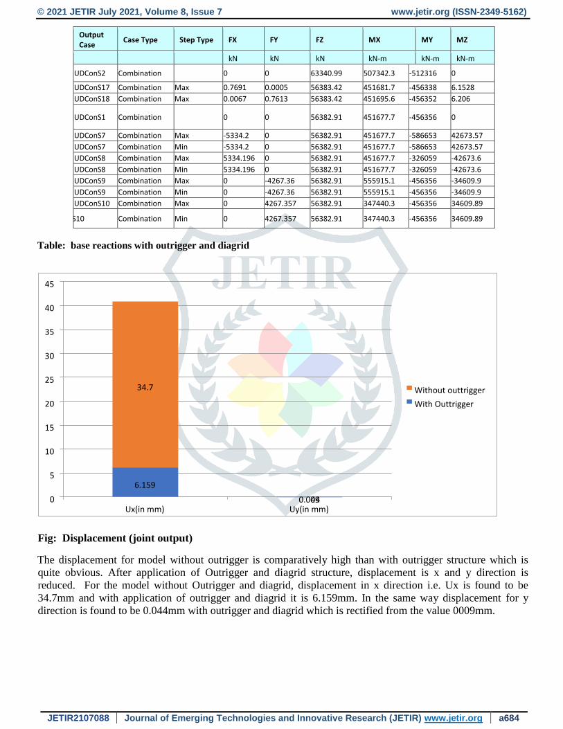
Table: base reactions with outrigger and diagrid
Fig: Displacement (joint output)
The displacement for model without outrigger is comparatively high than with outrigger structure which is
quite obvious. After application of Outrigger and diagrid structure, displacement is x and y direction is
reduced. For the model without Outrigger and diagrid, displacement in x direction i.e. Ux is found to be
34.7mm and with application of outrigger and diagrid it is 6.159mm. In the same way displacement for y
direction is found to be 0.044mm with outrigger and diagrid which is rectified from the value 0009mm.
6.159
44
34.7
0.009 0
5
10
15
20
25
30
35
40
45
Ux(in mm) Uy(in mm)
Without outtrigger
With Outtrigger
© 2021 JETIR July 2021, Volume 8, Issue 7 www.jetir.org (ISSN-2349-5162)
JETIR2107088 Journal of Emerging Technologies and Innovative Research (JETIR) www.jetir.org a685
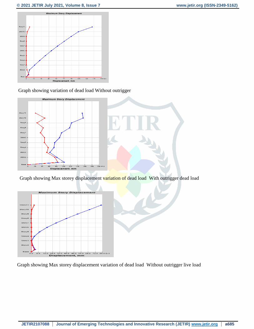
Graph showing variation of dead load Without outrigger
Graph showing Max storey displacement variation of dead load With outrigger dead load
Graph showing Max storey displacement variation of dead load Without outrigger live load

© 2021 JETIR July 2021, Volume 8, Issue 7 www.jetir.org (ISSN-2349-5162)
JETIR2107088 Journal of Emerging Technologies and Innovative Research (JETIR) www.jetir.org a686
Graph showing Max storey displacement variation of live load With outrigger
Graph showing Max storey displacement variation of live load Without outrigger earthquake in x direction
Graph showing Max storey displacement With outrigger earthquake in x direction
© 2021 JETIR July 2021, Volume 8, Issue 7 www.jetir.org (ISSN-2349-5162)
JETIR2107088 Journal of Emerging Technologies and Innovative Research (JETIR) www.jetir.org a687
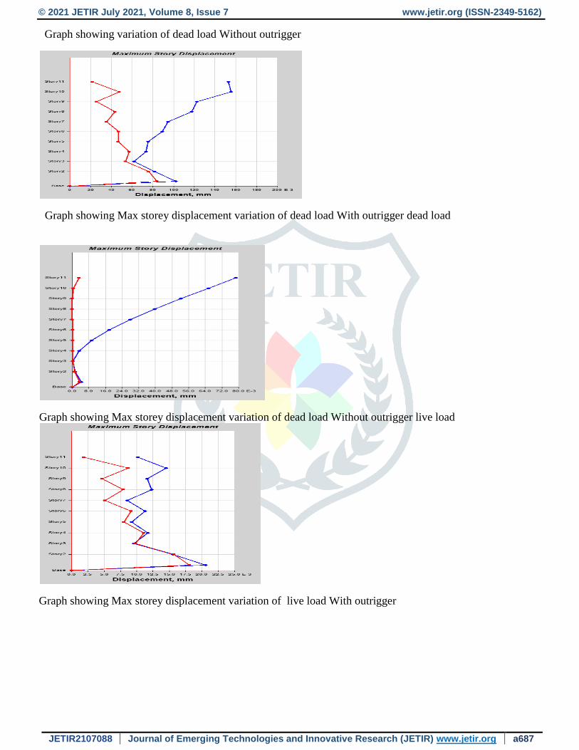
Graph showing variation of dead load Without outrigger
Graph showing Max storey displacement variation of dead load With outrigger dead load
Graph showing Max storey displacement variation of dead load Without outrigger live load
Graph showing Max storey displacement variation of live load With outrigger
© 2021 JETIR July 2021, Volume 8, Issue 7 www.jetir.org (ISSN-2349-5162)
JETIR2107088 Journal of Emerging Technologies and Innovative Research (JETIR) www.jetir.org a688
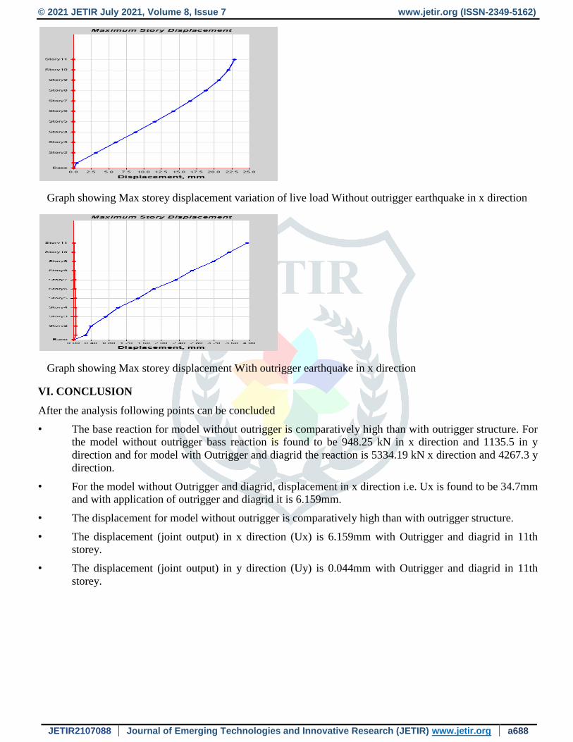
Graph showing Max storey displacement variation of live load Without outrigger earthquake in x direction
Graph showing Max storey displacement With outrigger earthquake in x direction
VI. CONCLUSION
After the analysis following points can be concluded
• The base reaction for model without outrigger is comparatively high than with outrigger structure. For
the model without outrigger bass reaction is found to be 948.25 kN in x direction and 1135.5 in y
direction and for model with Outrigger and diagrid the reaction is 5334.19 kN x direction and 4267.3 y
direction.
• For the model without Outrigger and diagrid, displacement in x direction i.e. Ux is found to be 34.7mm
and with application of outrigger and diagrid it is 6.159mm.
• The displacement for model without outrigger is comparatively high than with outrigger structure.
• The displacement (joint output) in x direction (Ux) is 6.159mm with Outrigger and diagrid in 11th
storey.
• The displacement (joint output) in y direction (Uy) is 0.044mm with Outrigger and diagrid in 11th
storey.

© 2021 JETIR July 2021, Volume 8, Issue 7 www.jetir.org (ISSN-2349-5162)
JETIR2107088 Journal of Emerging Technologies and Innovative Research (JETIR) www.jetir.org a689
VII. REFERENCES
[1] ANALYSIS-OF-A-HIGH-RISE-BUILDING-FRAME-CONSIDERING-LATERAL-LOAD-
RESISTING-MEMBERS-A-REVIEpdf Mohit Kumar Prajapati, International Journal of Civil Engineering
and Technology (IJCIET) Volume 12, Issue 3, March 2021, pp. 1-4, Article ID: IJCIET_12_03_001
[2] Comprehensive Analysis of Outrigger Building System 2020, THEJAS H KLaxmi SAbhilash D
TInternational Journal of Civil Engineering and Technology 11(1), 25-31, 2020H K, Thejas and S, Laxmi
and D T, Abhilash, Comprehensive Analysis of Outrigger Building System (2020). International Journal of
Civil Engineering and Technology 11(1), 25-31, 2020, Available at
SSRN:https://ssrn.com/abstract=3534565
[3] Design and Analysis of Core and Outrigger Structural System 2020, Krutagn Patel, Prof. Vishal
kumarpatel Dr. Snehal Mevada, International Research Journal of Engineering and Technology (IRJET) e-
ISSN: 2395-0056 Volume: 07 Issue: 06 | June 2020 www.irjet.net p-
ISSN: 2395-0072 pgno-3026-3033