Embed Size (px)
Citation preview

COMPARISON OF TWO AND THREE PLATE MOLDS PLASTIC INJECTION
MOLDING FOR MOLD DESIGN SELECTION
AHMAD FAIZOL BIN ISMAIL
UNIVERSITI TEKNIKAL MALAYSIA MELAKA
I admit that had read this dissertation and in my opinion this dissertation is
satisfactory in the aspect of scope and quality for the bestowal of Bachelor of
Mechanical Engineering (Structure and Material)
Signature : ………………
Supervisor Name : MOHD RIZAL BIN ALKAHARI
Date : ………………

COMPARISON OF TWO AND THREE PLATE MOLDS PLASTIC INJECTION
MOLDING FOR MOLD DESIGN SELECTION
AHMAD FAIZOL BIN ISMAIL
This report is proposed to fulfilled some of the requirements to be honor with
Bachelor of Mechanical Engineering (Structure and Material)
Faculty of Mechanical Engineering
Universiti Teknikal Malaysia Melaka
MAY 2009

ii
“I verify that this report is my own work except for the citation and quotation that the source has been clarify for each one of them”
Signature :………………………..
Author : AHMAD FAIZOL BIN ISMAIL
Date :………………………..

iii
To my beloved family for their encouragement and support especially, and for their
understanding in the way I am.

iv
ACKNOWLEDGMENT
First of all, thank to Allah the almighty for the strength and blessing for me
to accomplished this report to fulfill the course requirements of Project Sarjana
Muda II (BMCU 4983).
I would like to give appreciation especially to my supervisor, Encik Mohd
Rizal Bin Alkahari for supervising me at all the way in conducting the research to
complete my Projek Sarjana Muda course.
Appreciation is also to all lectures, technicians and staffs of Faculty of
Mechanical, Universiti Teknikal Malaysia Melaka.
I would like to express my gratitude to my family for their patience and
encouragement, also to all my friends who have been very helpful either directly or
indirectly. I hope this research will be helpful to others in the future.
v
ABSTRACT
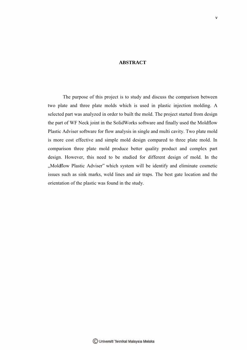
The purpose of this project is to study and discuss the comparison between
two plate and three plate molds which is used in plastic injection molding. A
selected part was analyzed in order to built the mold. The project started from design
the part of WF Neck joint in the SolidWorks software and finally used the Moldflow
Plastic Adviser software for flow analysis in single and multi cavity. Two plate mold
is more cost effective and simple mold design compared to three plate mold. In
comparison three plate mold produce better quality product and complex part
design. However, this need to be studied for different design of mold. In the
„Moldflow Plastic Adviser‟ which system will be identify and eliminate cosmetic
issues such as sink marks, weld lines and air traps. The best gate location and the
orientation of the plastic was found in the study.

vi
ABSTRAK
Kajian ini adalah bertujuan untuk mengkaji perbandingan diantara dua plet
dan tiga plet acuan bagi „plastic injection molding‟. Dua plet acuan mencirikan satu
produk yang kualitinya rendah berbanding tiga plet acuan yang berkualiti tinggi
tetapi harganya jauh lebih murah berbanding tiga plet acuan. Selain itu, proses
pembuatan bagi dua plet acuan ini lebih rendah dan memerlukan kemahiran daripada
individu. Kualiti produk bagi pemilihan acuan ini melibatkan tahap acuan dari segi
pengaliran cecair dan tegangan kekuatannya untuk membentuk produk dalam
keadaan baik tanpa kecacatan permukaannya. Penggunaan simulasi Moldflow
Plastic Adviser (MPA) ini dapat mempertingkatkan kualiti sesuatu produk itu
dengan tahap maksimum yang mengikut prosedur untuk kualiti tinggi merangkumi
segala aspek. Simulasi MPA ini secara tidak langsung dapat mengurangkan kos
perbelanjaan dalam proses penghasilan produk dengan menganalisis awal bagi
menghasilkan produk bermutu tinggi dengan kos yang rendah. Dalam simulasi MPA
ini dapat mempertingkatkan keberkesanan bahan acuan bagi produk pengikat kipas
dinding.

ii
TABLE OF CONTENTS
CHAPTER ITEMS PAGE
DEDICATION iii
ACKNOWLEDGMENT iv
ABSTRACT v
ABSTRAK vi
TABLE OF CONTENTS vii
LIST OF TABLES xii
LIST OF FIGURES xiii
LIST OF APPENDIXS xvii
CHAPTER 1 INTRODUCTION 1
1.1 Background 1
1.2 Objective 2
1.3 Scope 3
1.4 Problem Statement 3
1.5 Outline of research 3
1.5.1 Literature Review 3
1.5.2 Methodology 4
1.5.3 Project Analysis 5
1.5.4 Discussion 5

viii
CHAPTER 2 LITERATURE REVIEW 6
2.1 Plastic Injection Molding 6
2.1.1 Injection Molding Materials 7
2.2 Molds 8
2.2.1 Design of Molds 10
2.2.2 Mold components 13
2.3 Injection Process 17
2.3.1 Injection molding cycle 17
2.3.2 Elements of the Injection 19
Molding Process
2.3.3 Molding Defects 21
CHAPTER 3 METHODOLOGY 22
3.1 Process Flow 22
3.2 Mold Design 23
3.2.1 Two plate molds 23
3.2.2 Three plate molds 24
3.3 Quality of Molds 25
3.4 Moldflow Plastic Advisers (MPA) 26
3.4.1 Quality Prediction Testing 27
3.4.2 Applications by using the MPA
analyze method 28
3.5 User interface & MPA Preferences 29
3.5.1 Toolbars 29
3.5.2 Tasks Panel 30
3.5.3 Projects and Working Studies 31
3.6 The case study for MPA analysis 32
3.7 Workflow Procedure 33
3.7.1 Part Only Result 33

ix
3.7.2 Two plate molds workflow 33
3.7.3 Three plate molds workflow 33
CHAPTER 4 RESULT & ANALYSIS 36
4.1 Analysis of WF Neck Joint design 36
4.2 Part Only of Moldflow Simulation 36
4.2.1 Best Gate Location 37
4.2.2 Molding window analysis 38
4.2.3 Fill and cycle time 39
4.2.4 Plastic flow 40
4.2.5 Confidence of fill 41
4.2.6 Quality prediction 41
4.2.7 Pressure at end of the fill 42
4.2.8 Temperature at flow front 42
4.2.9 Pressure drop 43
4.2.10 Orientation at skin 44
4.2.11 Average temperature 42
4.2.12 Air trap 45
4.2.13 Frozen layer 46
4.2.14 Grow Form 46
4.2.15 Weld line 47
4.2.16 Fill and cycle process 48
4.2.17 Time to reach ejection temperature 49
4.2.18 Volumetric shrinkage at ejection 50
4.2.19 Sink mark 51
4.3 Static Analysis of Cosmos software 52
4.3.1 Stress 52
4.3.2 Displacement 53
4.4 Comparison two plate and three plate molds 54

x
4.4.1 Molds 54
4.4.2 Cycle process 55
4.4.3 Fill time 56
4.4.4 Quality prediction 57
4.4.5 Pressure at end of fill 58
4.4.6 Pressure drop 59
4.4.7 Average Temperature 60
4.4.8 Temperature at flow front 61
4.4.9 Frozen layer fraction at end of fill 62
4.4.10 Air Trap 63
4.4.11 Weld line 64
4.4.12 Sink Marks 65
4.4.13 Grow Form 66
CHAPTER 5 DISCUSSIONS 67
CHAPTER 6 CONCLUSION 71
CHAPTER 7 RECCOMENDATION 72
REFERENCES 73
BIBLIOGRAPHY 75
APPENDIX 76

xii
LIST OF TABLE
TABLE TITLE PAGE
2.1 Acrylonitrile Butadiene Styrene (ABS) Specification 7
2.2 Thermoplastic Polymers Specification 8
2.3 Molding defect specification 21
4.1 Dimension of injection location 38
4.2 Molding window parameters 38
4.3 Filling Process Single Cavity 48
4.4 Cycle Process Single Cavity 48
4.5 Filling and packing for Single Cavity 49
4.6: Sink mark summary 51
5.1 Comparison of part only, single and multi cavity. 67
5.2 Comparison two and three plate molds 70

xiii
LIST OF FIGURE
FIGURE TITLE PAGE
1.1 Flow Chart Methodology 4
2.1 Graph comparison aluminium and steel 10
2.2 Parts of mold 11
2.3 Two plate mold in closed position 13
2.4 Two plate in an open position 14
2.5 Two Plate Mold shown at ejection 15
2.6 The illustration of two balance runner systems 16
2.7 Injection molding cycle 18
2.7 Injection Molding Elements 19
3.1 Flow of process including this study 22
3.2 A two plate mold 24
3.3 A three plate mold 25
3.4 Works Flow of MPA 27
3.5 Quality Prediction Testing 28
3.6 MPA Toolbar 30
3.7 MPA Task Panel 31
3.8 MPA working flow 32
3.9 The existing product of WF neck joint 34
3.10 3D modeling in Solidwork software 35
4.1 Best Gate Location 37
4.2 Dimension of injection location 37
xiv
4.3 Molding window analysis 38
4.4 Filling Time 39
4.5 Plastic flow 40
4.6 ` Confidence of fill 40
4.7 Quality prediction 41
4.8 Pressure at end of the fill 42
4.9 Temperature at flow front 42
4.10 Pressure drop 43
4.11 Orientation at skin 44
4.12 Average Temperature 44
4.13 Air Trap 45
4.14 Frozen Layer 46
4.15 Grow form 46
4.16 Weld line 47
4.17 Time to reach ejection temperature 49
4.18 Volumetric shrinkage at ejection 50
4.19 Sink marks 51
4.20 Analysis stress of body 52
4.21 Analysis displacement of body 53
4.22 Comparison of molds 54
4.23 Comparison of cycle process 55
4.24 Comparison of fill time 56
4.25 Comparison of quality prediction 57
4.26 Comparison of pressure at end of fill 58
4.27 Comparison of pressure drop 59
4.28 Comparison of average temperature 60
4.29 Comparison of temperature at flow front 61
4.30 Comparison of frozen layer fraction at end of fill 62
4.31 Comparison of Air Trap 63
4.32 Comparison of Weld line 64
4.33 Comparison of Sink Marks 65
4.34 Comparison of Grow Form 66

xvi
LIST OF APPENDIX
NO. TITLE PAGE
A Properties of Common Plastic – ABS 76
B Hydraulic Clamp Plastic injection Molding 77
C Existing product of WF Neck Joint (Wall Fan) 78
D 3D Drawing of product 79
E WF Neck Joint 2D Drawing 80
F WF Neck Plate 2D Drawing 81

1
CHAPTER 1
INTRODUCTION
1.1 Background
The plastic injection molding process engaged the injection of a plastic
material melt into a closed mold, at point the plastic cools and solidifies to form a
specific product. The action that takes place is much like a three phase process
comprising filling, packing and cooling phase. In its simplest form, is like the
operation of a plunger needle that a barrel contains heated plastic that is injected by
used of a plunger or auger device into a closed mold that contains a machined,
reverse image of the desire product. While this may seem simple, the process
actually involves many individual activities and parameters that must be tightly
controlled to produce a high-quality product at a reasonable cost. The primary
advantage of this process is that many functions and features can be incorporated
into the product design. This process will minimize, or eliminate, the amount of
secondary work required to produce the same product in other ways or using other
materials. Its popularity is typified by the numerous products produced in this way at
present time (Brydson, 1999).
Mold is the production tooling used to produce plastic parts in molding. The
plastic product begins life in the mold. The mold produces the final shape of the
product before it is ejected out into the world to perform its intended function. In
addition, the process is fast, usually requiring less than one minute for a complete

2
product. The multiple cavity images can be placed in the mold, many products can
be produced at the same time. This makes the cost of an individual part much lower
than if it was molded alone. In theory, the mold can be designed and built to create a
totally finished product, including painted surfaces, assembled units form individual
components and molded-in metal inserts (Crackwell, 1993).
The beginning of simulation software has made a major impact in the
industry where in the past, much was unknown about the injection process itself.
Indeed, it was known by only a handful of experts. To the resourceful user,
simulations can produce a variety of results on ail aspects of injection process.
Traditional trial runs on the factory floor can be replaced by less costly computer
simulations. The performance adviser adds the ability to simulate the packing phase
of the injection molding process to both part and mold. Use Moldflow Plastic
Adviser results to minimize undesirable part shrinkage as well as to assess whether a
part is likely to warp or deform beyond acceptable levels.
1.2 Objective
The purpose of this work are:
i) To compare two and three plate molds in plastic injection molding
process in form of design and product quality.
ii) To select the best mold design in term of good product quality.

3
1.3 Scope
The scopes of this study are:
i) Discover the differences between two and three plates for plastic
injection molding.
ii) The design analysis solution using a software „Moldflow Plastic
Adviser‟.
iii) To improve product quality and to identify eliminate sink marks, weld
lines and air traps.
1.4 Problem Statement.
The task was to selected the comparison two and three plate mold that can be
reducing the cost of the injection molding process and good product quality. The paper
study of flow analysis in mold using computer software analysis. The project was a
design modification of an existing product, not a totally new design from scratch.
1.5 Outline of Research.
The research outlines are as follows:
1.5.1 Literature review.
The principle and theories of the plastic injection molding. Then the comparison
of two and three plates of mold for were reviews from various sources such as journals,
books, previews reports and the world wide website. Summary of the literatures was
presented in Chapter 2.

4
1.5.2 Methodology
The methodology were divided into two phase which are the two plate and three
plates of plastic injection molding. Then the comparison of this part such as the design,
cost, product quality will be selected. The methodology of this task were described in
Chapter 3. The methodology of this study has been summarised in the flow chart
(Figure 1.1) below
Figure 1.1 Flow Chart Methodology
Objectives
Problem Statement
Literature Review
Methodology
Result & Analysis
Discussion, Summarize and Conclusion
Recommendation

5
1.5.3 Project Analysis.
The information that collected from the research were presented by using
statistical analysis. The details were also analyzed to obtain the effect of cost and
quality product by using statistical software analysis. Then select a new design and the
comparisons for each plates were done and the results were discussed in chapter 4.
1.5.4 Discussion.
All results that obtained in the research of this study were compiled and
discussed in chapter 5. Finally, the conclusion and recommendation for future research
were presented in Chapter 6 and Chapter 7.

6
CHAPTER 2
LITERATURE REVIEW
2.1 Plastic Injection Molding
The plastic injection molding is a process that consists of semi-inject the molten
polymer in a closed mold under pressure and cold, through a small hole called a gate.
Molten plastic is injected at high pressure into a mold, which is the inverse of the
product's shape. In that mold material solidifies starting to crystallize polymer semi. The
final part is obtained by opening the mold and remove the cavity of the molded part.
According to Knights (1997), In 1868 John Wesley Hyatt became the first to
inject hot celluloid into a mold, producing billiard balls. He and his brother Isaiah
patented an injection molding machine that used a plunger in 1872 and the process
remained more or less the same until 1946, when James Hendry built the first screw
injection molding machine, revolutionizing the plastics industry. Roughly 95% of all
molding machines now use screws to efficiently heat, mix, and inject plastic into molds.
The injection molding is a very popular technique for the manufacture of
different articles and provides low cost at moderate to large quantities. Plastic molding
is an extremely versatile process for producing a wide range of simple or complex
plastic parts with a good finish.

7
2.1.1 Injection Molding Materials
The huge majority of injection molding is applied to thermoplastic polymers.
The polymers being softened by heat and hardening on cooling even after repeated
cycling. In general, most of thermoplastic materials offer high impact strength, good
corrosion resistance, and easy processing with good flow characteristics for molding
complex designs (Boothroyd 1994).
The thermoplastic separated into two class that namely crystalline and
amorphous. Crystalline polymers have an ordered molecules arrangement with a
sharp melting point which its reflect most incident light and generally appear
opaque. They also undergo a high shrinkage or reduction in volume during
solidification. Crystalline polymers usually are more resistance to organic solvents
and have good fatigue and wear-resistance properties. Besides, this polymers also
are denser and have better mechanical properties than amorphous polymers.
Acrylonitrile Butadiene Styrene (ABS) is among the most popular and
versatile of the resins in the styrene family .Its availability, strength, and limited
shrinkage all help make it widely used as the default choice for most plastic
products. The ABS is an amorphous polymer with good impact strength and
excellent appearance. It is easy to process and is widely used for product has poor
chemical resistance.
Table 2.1: Acrylonitrile Butadiene Styrene (ABS) Specification
(Kenneth Budinski 2005)

8
Table 2.2: Thermoplastic Polymers Specification (Boothroyd et al. 1994)
2.2 Molds
Mold is the common term used to describe the production tooling used to
produce plastic parts in molding. The injection mold is the element of the injection
molding system that receives the molten plastic from the injection unit, forms the
shape of the desired plastic part, provides the necessary cooling to solidify the part
and ejects the part. The choice of material to build a mold from is primarily one of
economics, steel molds generally cost more to construct, but their longer lifespan
will offset the higher initial cost over a higher number of parts made before wearing
out.