Embed Size (px)
Citation preview

International Research Journal of Engineering and Technology (IRJET) e-ISSN: 2395-0056
Volume: 07 Issue: 04 | Apr 2020 www.irjet.net p-ISSN: 2395-0072
© 2020, IRJET | Impact Factor value: 7.529| ISO 9001:2008 Certified Journal | Page 2941
Comparative Study of Voided Bubble Deck Slab and U-Boot
Beton Deck Slab
Jaldhi Patel1, Harnisha Patel1, Vasav Desai1, Vatsal Desai1, Shaikh Mohd Saquib2
1Students, Dept. of Civil Engineering, Laxmi Institute of Technology – Sarigam, Gujarat, India 2Asst. professor, Dept. of Civil Engineering, Government Engineering College – Daman, India
-------------------------------------------------------------------------***-----------------------------------------------------------------------------
Abstract - Bubble deck slab is a slab which is created by inserting voids in the form of bubbles which reduces dead weight and is an eco-friendly practice. In this method, all the concrete which is not performing any structural function is removed. This reduces the dead weight of the structure. High density polyethylene hollow spheres are used which replace the in-effective concrete in the center of the slab. The advantages are reduced weight, savings in materials, faster construction time, less emission of exhaust gases and it is also a green technology. U-Boot beton deck slab is a modern technology which is used to create lightened two-way voided slabs in reinforced concrete structures. U-Boot beton is a box-like formwork structure which is made up of recycled polypropylene. The use of U-Boot beton helps in reducing the dead weight of the structure. This technology is light, quick and easy to position. It is an eco-friendly technology as it uses recycled materials and it does not emit any toxic substances. It also provides great resistance against fire. In this paper, we have designed a voided Bubble Deck Slab and U-Boot beton Deck Slab. The main aim is to compare the design and the overall cost of constructing Bubble Deck Slab and U-Boot beton Deck Slab.
Key Words: Bubble Deck, U-Boot beton, Voided, Slab, Hollow slab, Fire resistance, HDPE spheres, Box formwork
1. INTRODUCTION Bubble deck slab is a biaxial hollow core slab invented in Denmark. Bubble deck slab is a method of virtually eliminating all concrete from the middle of a floor slab, which is not performing any structural function, thereby considerably reducing structural dead weight. High density polyethylene hollow spheres replace the in- effective concrete in the centre of the slab, thus decreasing the dead weight and increasing the efficiency of the floor. Bubble deck slab is constructed by placing prefabricated plastic bubbles and the reinforcement is then placed between and over plastic bubbles and lastly, fresh concrete is poured. The gaps leads to 30 to 50% lighter slab which reduces the loads on the columns, walls and foundations, and of course on the entire building. Bubble deck slab floor can offer the requisite load-bearing capacity at a smaller thickness. This leads to an additional advantage, resulting in a saving of 40 to 50 % of the material consumption in the floor construction. Since the weight of the structure is reduced, this type of structure can be useful to reduce earthquake damage. Bubble deck slab is a new innovative and sustainable floor system to be used as a self-supporting concrete floor.
U-Boot Beton is a recycled polypropylene formwork that was designed to create two-way voided slabs. The U-Boot Beton
formwork builds a grid work of mutually perpendicular beams in the concrete casting. These beams are closed from the bottom and the top by a flat plate that is created with a single casting. This results in considerable reduction in the use of concrete and steel. U-Boot Beton is used to create slabs with large span or that are able to support large loads without beams. This technology is light, quick and easy to position. Due to their modularity the designer can vary the geometric parameters as needed to adapt to all situations. This, in turn, gives great architectural freedom. U-Boot Beton is not subject to deformations, either during or after the casting, either due to the weight of the concrete or the dynamic effect connected to the work operations.
2. LITERATURE REVIEW Extensive literature study has been carried out from national and international journals. These literatures are classified as journals, documents collected from web etc. Abstracts of some literature are included here for the review.

International Research Journal of Engineering and Technology (IRJET) e-ISSN: 2395-0056
Volume: 07 Issue: 04 | Apr 2020 www.irjet.net p-ISSN: 2395-0072
© 2020, IRJET | Impact Factor value: 7.529| ISO 9001:2008 Certified Journal | Page 2942
2.1 Experimental study on bubble deck slab by Mr. Muhammad Shafiq Mushfiq, Shikha Saini, Nishant Rajoria
In this literature, slabs of three kind were tested, one without bubbles (conventional) and two with bubbles. Then they have compared the load bearing capacity of bubble deck slab with conventional slab. It was observed that the bubble deck slabs were not as efficient as the conventional slab, (having lesser load bearing capacity), but they are very much acceptable in slab construction keeping in view the trifling difference in load bearing capacity.
2.2 Study on Structural Behaviour of Bubble Deck Slab using Indian Standards by Immanuel Joseph Chacko, Sneha M. Varghese
In this paper, the authors have studied the structural behaviour of Bubble Deck Slab using Indian Standards by varying
parameters like ball diameter variation. They have studied various factors such as load vs deflection characteristics and load vs strain characteristics and ultimate load. The specimens were tested on a 50 ton loading frame with a load cell of capacity 50 Ton.
2.3 An experimental study on two way bubble deck slab with spherical hollow balls by Bhagyashri G. Bhade and S.M Barelikar
In this paper, authors have compared different parameters between solid conventional slab and bubble deck slab. Parameters which have been compared include load carrying capacity, deflection behavior and weight of the slab. The tested slabs were simply supported and were loaded with a single point load.
2.4 Study of U-Boot Technology in Construction by Ramvath Srikanth, Nampally Anil Kumar, Sandhyaveni Srinath, Chitta Anudeep, Snehalatha Bakshetty
In this paper, the authors have studied about the different properties, parts, sizes and types of U- Boot beton technology. There are mainly 2 types for arranging U-boot betons – Single U-Boot beton and Double U-Boot beton. Parts of U-Boot beton includes foots, U-Boot beton, Spacer joint, Connection bridge and Closing plate. Further the authors have also studied the concepts, advantages, applications and installation of U-Boot beton.
2.5 Modelling and analysis of flyover deck slab with U-Boot technology by Dr. H. Sudarsana Rao and M. Surya Prasanth
The authors have done modeling and analysis of Flyover Deck slab with U-Boot technology in this paper. For modeling of flyover the following components are assembled- Pile, Pile cap, Pier, Pier cap, Bed Block, Rocker and Pin Bearing, Deck Slab with U-Boot. The Project compares two types of flyover i.e., Flyover deck slab With U-Boot and Flyover deck slab without U-Boot. NX-Nastran software has been used for analyzing the model of Flyover Deck slab. The parameters such as maximum principal stress, maximum shear stress and displacements in deck slab have been given due consideration. The comparison of costs of concrete and steel has also been shown.
3. DESIGN METHODOLOGY The Direct Design Method has been used for designing this slab system. In this method, total moment is calculated and then it is distributed to total negative moment and total positive moment. All the negative and positive moments are distributed in the column strips and middle strips respectively.
3.1 Limitations Slab system designed by the direct design method should accomplish the following conditions: a) There shall be minimum of three continuous spans in each direction, b) The panels shall be rectangular, and the ratio of the longer span to the shorter span within a panel shall not be greater than 2.0

International Research Journal of Engineering and Technology (IRJET) e-ISSN: 2395-0056
Volume: 07 Issue: 04 | Apr 2020 www.irjet.net p-ISSN: 2395-0072
© 2020, IRJET | Impact Factor value: 7.529| ISO 9001:2008 Certified Journal | Page 2943
c) It shall be permissible to offset columns to a maximum of 10 percent of the span in the direction of the offset notwithstanding the provision in (b) d) The successive span lengths in each direction shall not differ by more than one-third of the longer span. The end spans may be shorter but not longer than the interior spans, and e) The design live load shall not surpass three times the design dead load.
3.2 Total Design Moment
In the direct design method, the total design moment for a span shall be determined for a strip bounded laterally by the centre-line of the panel on each side of the centre-line of the supports. The absolute sum of the positive and negative bending moments in each direction shall be taken as:
M0 =
where, M0 = Total moment W = Design load on the area L2Ln Ln= Clear span extending from face to face of columns, capitals, brackets or walls but not less than 0.65 L1 L1 = Length of span in the direction of M0; and L2 = Length of span transverse to L1
3.3 Negative and Positive Design Moments
The total design moment M0 in a panel is to be distributed into negative moment and positive moment as specified below:
In an interior span
Negative Design Moment = 0.65 M0
Positive Design Moment = 0.35 M0
In an end span
Interior negative design moment:
Positive design moment:
Exterior negative design moment:
where is the ratio of flexural stiffness of the exterior columns to the flexural stiffness of the slab at a joint taken in the direction moments are being determined and is given by
∑
where,
Kc = Sum of the flexural stiffness of the columns meeting at the joint; and
Ks = Flexural stiffness of the slab, expressed as moment per unit rotation.

International Research Journal of Engineering and Technology (IRJET) e-ISSN: 2395-0056
Volume: 07 Issue: 04 | Apr 2020 www.irjet.net p-ISSN: 2395-0072
© 2020, IRJET | Impact Factor value: 7.529| ISO 9001:2008 Certified Journal | Page 2944
4. PROBLEM STATEMENT AND LOAD CALCULATION One of the most common components in modern building construction is reinforced concrete slab which consume a lot of concrete. Due to the shear amount of concrete required to produce these slabs, the dead weight of these slabs tend to be very large. Lighter structures are more preferable to heavier structures in seismically active regions. In our project, we have discussed about the significance of Bubble Deck slab and U-Boot beton Deck slab over traditional conventional slab. Bubble Deck and U-Boot are recycled polypropylene formwork technology which is used for construction purposes. The use of voided slab helps to create light economical design for the structure. This technology is used to create slabs with large spans or to construct the slabs which support large loads without beams. This type of construction is suitable for high rise buildings, hospitals, parking facilities and for residential and industrial buildings. The most significant cost-effective, practical and operational advantages provided by voided slab for the entire structure includes less use of reinforcement in slabs, columns and foundation up to a total of 15%, less concrete usage, reduced building weight, the architectural freedom of the structure and possibility of slimmer columns and foundations and thus lower cost related to excavation for foundations.
4.1 Structural Loads
The loads acting on the slab may be categorized as:
Dead Load Live Load Floor Finish
4.1.1 Dead Loads
Dead Loads, are those which are associated with the weight of the structure itself. These loads remain stationary and relatively constant over time.
For Bubble Deck slab:
Dead Load = Effective volume * Density of concrete * width
Effective volume = 0.24 m3
Width = 1000 mm
Density of concrete =25N/mm2
Dead Load = 0.24 *25
= 6 kN/m2
For U-Boot beton Deck slab:
Dead Load = Effective volume * Density of concrete * width
Effective volume = 0.0481*6 = 0.288 m3
Width = 1000 mm
Density of concrete =25N/mm2
Dead Load = 0.288 *25
= 7.129 kN/m2
4.1.2 Live Load
Live Loads which are also known as applied or imposed loads or variable actions may vary over time. Live load is assumed in accordance with IS 875 (Part-II) - 1987

International Research Journal of Engineering and Technology (IRJET) e-ISSN: 2395-0056
Volume: 07 Issue: 04 | Apr 2020 www.irjet.net p-ISSN: 2395-0072
© 2020, IRJET | Impact Factor value: 7.529| ISO 9001:2008 Certified Journal | Page 2945
Live load = 4kN/m2 | IS 875 (Part -2)
4.1.3 Floor Finish
Floor Finish = 1kN/m2 | IS 875 (Part –2)
5. MODELLING AND DESIGN
5.1 Model Data for Bubble Deck slab
Size of Panel = 21m x 21m Size of Column = 400mm x 400mm Floor to floor height = 3 m fck = 25 N/mm2 fy = 415 N/mm2 Dead Load = 6 kN/m Live Load = 4 kN/m Floor Finish = 1 kN/m
Fig -1: Structural Layout of the panel
5.2 Design of slab
Based on span and end conditions, the entire floor system can be grouped into 3 groups.
S1 = Corner Panel
S2 = Exterior Panel
S3 = Interior Panel

International Research Journal of Engineering and Technology (IRJET) e-ISSN: 2395-0056
Volume: 07 Issue: 04 | Apr 2020 www.irjet.net p-ISSN: 2395-0072
© 2020, IRJET | Impact Factor value: 7.529| ISO 9001:2008 Certified Journal | Page 2946
5.2.1 Design of Interior Panel (S3)
Reinforcement Details
270 mm2
D = 200 mm2
Table -1: Reinforcement Details for Interior Panel
Strip Moment Ast Bar Diameter Spacing Ast provided
Along X Zone 1 -60.54 906 12 120 942.42 Zone 2 26.079 372 12 300 376.9 Zone 3 -20.18 286 12 300 376.9 Zone 4 17.386 245.8 12 400 282.7 Along Y
Zone 1 -60.54 906 12 120 942.42 Zone 2 -20.18 286 12 300 376.9
Zone 3 26.079 372 12 300 376.9 Zone 4 17.386 245.8 12 400 282.7
5.2.2 Design of Corner Panel (S1)
Effective depth of slab = 200 mm
Effective depth of drop = 200 + 100 = 300 mm
Reinforcement Details
Table -2: Reinforcement Details for Corner Panel Strip Moment Ast Bar Diameter Spacing Ast provided
Along X Zone 1 (exterior)
-41.14 599.88 12 150 753.9
Zone 1 (interior)
-65.11 982 12 100 1130.9
Zone 2 36.3 525.9 12 200 565.45
Zone 3 (interior)
-21.7 308.56 12 300 376.96
Zone 4 24.2 345.19 12 300 376.96
Along Y
Zone 1 (exterior)
-41.14 599.88 12 150 753.9
Zone 1 (interior)
-65.11 982 12 100 1130.9
Zone 2 (interior)
-21.7 308.56 12 300 376.96
Zone 3 36.3 525.9 12 200 565.45
Zone 4 24.2 345.19 12 300 376.96

International Research Journal of Engineering and Technology (IRJET) e-ISSN: 2395-0056
Volume: 07 Issue: 04 | Apr 2020 www.irjet.net p-ISSN: 2395-0072
© 2020, IRJET | Impact Factor value: 7.529| ISO 9001:2008 Certified Journal | Page 2947
5.2.3 Design of Exterior Panel (S2) Reinforcement details
Table -3: Reinforcement Details for Exterior Panel
Strip Moment Ast Bar Diameter Spacing Ast provided Along X
Zone 1 (exterior)
-34.75 502 12 200 565.45
Zone 1 (interior)
-64.5 972.1 12 110 1028
Zone 2 34.96 505.6 12 220 514.04
Zone 3 (interior)
-21.5 305.6 12 300 376.9
Zone 4 23.3 331.97 12 300 376.9
Along Y
Zone 1 (exterior)
-34.75 502 12 200 565.45
Zone 1 (interior)
-64.5 972.1 12 110 1028
Zone 2 (interior)
-21.5 305.6 12 300 376.9
Zone 3 34.96 505.6 12 220 514.04
Zone 4 23.3 331.97 12 300 376.9
5.3 Model Data for U-Boot beton Deck Slab
Size of Panel = 21m x 21m Size of Column = 400mm x 400mm Floor to floor height = 3 m fck = 25 N/mm2 fy = 415 N/mm2 Dead Load = 7.219 kN/m Live Load = 4 kN/m Floor Finish = 1 kN/m
5.4 Design of slab
Based on span and end conditions, the entire floor system can be grouped into 3 groups.
S1 = Corner Panel
S2 = Exterior Panel
S3 = Interior Panel

International Research Journal of Engineering and Technology (IRJET) e-ISSN: 2395-0056
Volume: 07 Issue: 04 | Apr 2020 www.irjet.net p-ISSN: 2395-0072
© 2020, IRJET | Impact Factor value: 7.529| ISO 9001:2008 Certified Journal | Page 2948
5.4.1 Design of Interior Panel (S3)
Reinforcement Details
270 mm2
D = 200 mm2
Table -4: Reinforcement Details for Interior Panel
Strip Moment Ast Bar Diameter Spacing Ast provided
Along X
Zone 1 -67.25 1045.2 12 100 1130.97
Zone 2 28.97 419.66 12 250 452.39
Zone 3 -22.42 321.22 12 300 376.99
Zone 4 19.31 275.48 12 400 282.74
Along Y
Zone 1 -67.25 1045.2 12 100 1130.97
Zone 2 -22.42 419.66 12 300 376.99
Zone 3 28.97 321.22 12 250 452.39
Zone 4 19.31 275.48 12 400 282.74
5.4.2 Design of Corner Panel (S1)
Effective depth of slab = 200 mm
Effective depth of drop = 200 + 100 = 300 mm
Reinforcement Details
Table -5: Reinforcement Details in Corner Panel Strip Moment Ast Bar Diameter Spacing Ast provided
Along X
Zone 1 (exterior)
-26.07 375.89 12 300 376.99
Zone 1 (interior)
-72.59 1140.78 12 90 1256.63
Zone 2 40.92 604.91 12 180 628.31
Zone 3 (interior)
-24.19 347.80 12 300 376.99
Zone 4 27.27 394.07 12 280 403.91
Along Y
Zone 1 (exterior)
-26.07 375.89 12 300 376.99
International Research Journal of Engineering and Technology (IRJET) e-ISSN: 2395-0056
Volume: 07 Issue: 04 | Apr 2020 www.irjet.net p-ISSN: 2395-0072
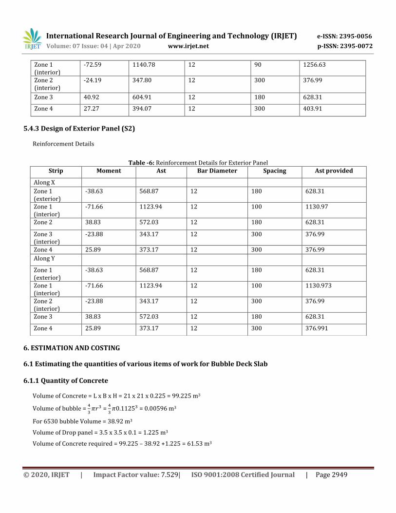
© 2020, IRJET | Impact Factor value: 7.529| ISO 9001:2008 Certified Journal | Page 2949
Zone 1 (interior)
-72.59 1140.78 12 90 1256.63
Zone 2 (interior)
-24.19 347.80 12 300 376.99
Zone 3 40.92 604.91 12 180 628.31
Zone 4 27.27 394.07 12 300 403.91
5.4.3 Design of Exterior Panel (S2)
Reinforcement Details
Table -6: Reinforcement Details for Exterior Panel
6. ESTIMATION AND COSTING
6.1 Estimating the quantities of various items of work for Bubble Deck Slab 6.1.1 Quantity of Concrete
Volume of Concrete = L x B x H = 21 x 21 x 0.225 = 99.225 m3
Volume of bubble =
=
= 0.00596 m3
For 6530 bubble Volume = 38.92 m3
Volume of Drop panel = 3.5 x 3.5 x 0.1 = 1.225 m3
Volume of Concrete required = 99.225 – 38.92 +1.225 = 61.53 m3
Strip Moment Ast Bar Diameter Spacing Ast provided
Along X
Zone 1 (exterior)
-38.63 568.87 12 180 628.31
Zone 1 (interior)
-71.66 1123.94 12 100 1130.97
Zone 2 38.83 572.03 12 180 628.31
Zone 3 (interior)
-23.88 343.17 12 300 376.99
Zone 4 25.89 373.17 12 300 376.99
Along Y
Zone 1 (exterior)
-38.63 568.87 12 180 628.31
Zone 1 (interior)
-71.66 1123.94 12 100 1130.973
Zone 2 (interior)
-23.88 343.17 12 300 376.99
Zone 3 38.83 572.03 12 180 628.31
Zone 4 25.89 373.17 12 300 376.991
International Research Journal of Engineering and Technology (IRJET) e-ISSN: 2395-0056
Volume: 07 Issue: 04 | Apr 2020 www.irjet.net p-ISSN: 2395-0072
© 2020, IRJET | Impact Factor value: 7.529| ISO 9001:2008 Certified Journal | Page 2950
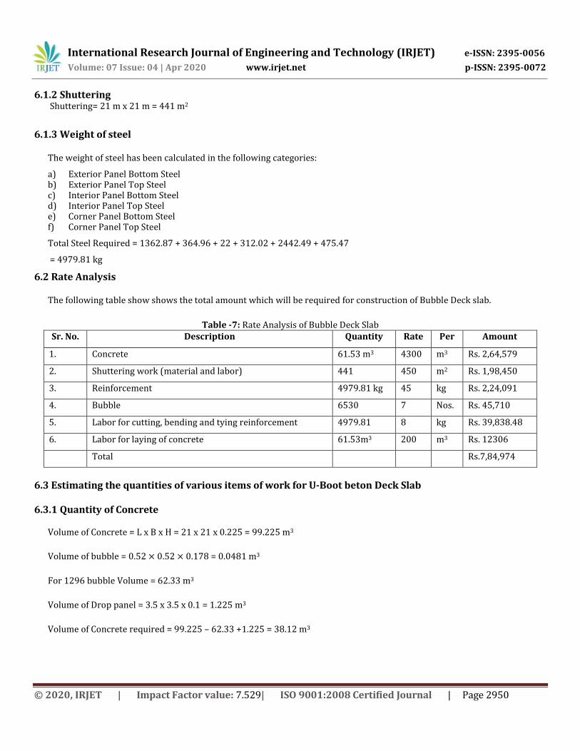
6.1.2 Shuttering Shuttering= 21 m x 21 m = 441 m2
6.1.3 Weight of steel
The weight of steel has been calculated in the following categories:
a) Exterior Panel Bottom Steel b) Exterior Panel Top Steel c) Interior Panel Bottom Steel d) Interior Panel Top Steel e) Corner Panel Bottom Steel f) Corner Panel Top Steel
Total Steel Required = 1362.87 + 364.96 + 22 + 312.02 + 2442.49 + 475.47
= 4979.81 kg
6.2 Rate Analysis
The following table show shows the total amount which will be required for construction of Bubble Deck slab.
Table -7: Rate Analysis of Bubble Deck Slab Sr. No. Description Quantity Rate Per Amount
1. Concrete 61.53 m3 4300 m3 Rs. 2,64,579
2. Shuttering work (material and labor) 441 450 m2 Rs. 1,98,450
3. Reinforcement 4979.81 kg 45 kg Rs. 2,24,091
4. Bubble 6530 7 Nos. Rs. 45,710
5. Labor for cutting, bending and tying reinforcement 4979.81 8 kg Rs. 39,838.48
6. Labor for laying of concrete 61.53m3 200 m3 Rs. 12306
Total Rs.7,84,974
6.3 Estimating the quantities of various items of work for U-Boot beton Deck Slab 6.3.1 Quantity of Concrete
Volume of Concrete = L x B x H = 21 x 21 x 0.225 = 99.225 m3
Volume of bubble = = 0.0481 m3
For 1296 bubble Volume = 62.33 m3
Volume of Drop panel = 3.5 x 3.5 x 0.1 = 1.225 m3
Volume of Concrete required = 99.225 – 62.33 +1.225 = 38.12 m3

International Research Journal of Engineering and Technology (IRJET) e-ISSN: 2395-0056
Volume: 07 Issue: 04 | Apr 2020 www.irjet.net p-ISSN: 2395-0072
© 2020, IRJET | Impact Factor value: 7.529| ISO 9001:2008 Certified Journal | Page 2951
6.3.2 Shuttering
Shuttering = 21 m x21 m = 441 m2
6.3.3 Weight of steel
The weight of steel has been calculated in the following categories: a) Exterior Panel Bottom Steel b) Exterior Panel Top Steel c) Interior Panel Bottom Steel d) Interior Panel Top Steel e) Corner Panel Bottom Steel f) Corner Panel Top Steel
Total Steel Required = 1457.49 + 406.97 + 355.94 + 45.02 + 1014.12 + 254.73
= 3534.27 kg
6.4 Rate Analysis
The following table shows the total amount which will be required for construction of U-Boot beton Deck slab.
Table -8: Rate Analysis of U-Boot beton Deck Slab Sr. No. Description Quantity Rate Per Amount
1. Concrete 38.12 m3 4300 m3 Rs. 1,63,916
2. Shuttering work (material and labor) 441 450 m2 Rs. 1,98,450
3. Reinforcement 3534.27 kg 45 kg Rs. 1,59,042
4. U-Boot 1296 8.5 Nos. Rs. 11,016
5. Labor for cutting, bending and tying reinforcement 3534.27 8 kg Rs. 28,275
6. Labor for laying of concrete 38.12 m3 200 m3 Rs. 7,624
Total Rs. 5,68,323
6.5 Comparison between Bubble Deck Slab and U-Boot Beton Deck Slab
Table -9: Comparison of rates Sr. No. Description
Amount (Bubble
Deck) Amount (U-Boot)
1. Concrete Rs. 2,64,579 Rs. 1,63,916
2. Shuttering work (material and labor) Rs. 1,98,450 Rs. 1,98,450
3. Reinforcement Rs. 2,24,091 Rs. 1,59,042
4. Bubble / U-Boot Rs. 45,710 Rs. 11,016
5. Labor for cutting, bending and tying reinforcement Rs. 39,838.48 Rs. 28,275
6. Labor for laying of concrete Rs. 12,306 Rs. 7,624
Total Rs. 7,84,974 Rs. 5,68,323

International Research Journal of Engineering and Technology (IRJET) e-ISSN: 2395-0056
Volume: 07 Issue: 04 | Apr 2020 www.irjet.net p-ISSN: 2395-0072
© 2020, IRJET | Impact Factor value: 7.529| ISO 9001:2008 Certified Journal | Page 2952
Chart -1: Graph showing comparison of rates
7. CONCLUSION Based on our study regarding U-Boot beton Deck slab system, the following conclusions can be made: The Bubble Deck slab is a technology which helps us to cope up in the present scenario of the construction industries.
These slabs are more economical, easy to construct and environment friendly.
The volume of concrete required in Bubble Deck slab is less. This helps in the savings of materials.
Weight reduction is an important factor which is found in Bubble Deck slab. Reduction in the use of concrete helps to reduce self- weight of the slab. This in turn decreases the amount of load on slabs so that we can design the foundation of the buildings for smaller dead loads.
It helps in saving of cost by using bubbles in the slab.
The Bubble Deck technology is environment friendly and sustainable. It reduces the global CO2 emissions.
Bubble Deck slab is not applicable to slabs having limited thickness.
It requires skilled labour.
The voids in the slab provide excellent thermal insulation property.
It helps in saving time. Construction time can be shortened since Bubble Deck slabs can be precast. As there is considerable less concrete content in the slab, the casting time is quicker.
The Bubble Deck slab is a technology which helps us to cope up in the present scenario of the construction industries. These slabs are more economical, easy to construct and environment friendly.
The U-boot technology is an advanced, economical, eco-friendly and fastest method of construction of slab. This technology provides great resistance against fire. It provides good architectural freedom due to its innovative shape. It is an eco-friendly product due to the lack of dangerous substances in its composition and due to the lack of emissivity of
toxic substances. It requires skilled labours. It helps in saving of cost by using U-Boot in the slab.
0100000200000300000400000500000600000700000800000
Bubble Deck
U-Boot

International Research Journal of Engineering and Technology (IRJET) e-ISSN: 2395-0056
Volume: 07 Issue: 04 | Apr 2020 www.irjet.net p-ISSN: 2395-0072
© 2020, IRJET | Impact Factor value: 7.529| ISO 9001:2008 Certified Journal | Page 2953
REFERENCES [1] Mr. Muhammad Shafiq Mushfiq, Shikha Saini and Nishant Rajoria, “Experimental Study on Bubble Deck slab”, International Research Journal of Engineering and Technology(IRJET) , Volume:04 Issue:05|May 2017 , e-ISSN:2395-0056 [2] Bhagyashri G. Bhade and S.M Barelikar, “An Experimental Study on Two Way Bubble Deck Slab with Spherical Hollow
Balls”, International Journal of Recent Scientific Research (IJRSR), Vol. 7, Issue 6, ISSN:0976-3031
[3] Er. Immanuel Joseph Chacko and Er. Sneha M. Varghese, “Study on Structural Behavior of Bubble Deck Slab using Indian Standards”, International Journal of Innovative Research in Technology (IJIRT), Volume 3,Issue 4, ISSN: 2349-6002
[4] Nagma Fatma and Vinaysingh Chandrakar, To study Comparison between Conventional Slab and Bubble Deck Slab”, International Advanced Research Journal in Science, Engineering and Technology (IARJSET), Vol. 5, Issue 1, ISSN 2393-8021
[5] Bhagyashri G. Bhade and Y.R.Suryawanshi, “Structural Behavior on two way Bubble deck slab using hollow spherical balls” , Vishwakarma Journal of Engineering and Research (VJER), Volume 1, Issue 2, ISSN : 2456-8465
[6] Raj. R. Vakil and Dr. Mangulkar Madhuri Nilesh, “Comparative study of Bubble Deck slab and Solid Deck slab” , International Journal of Advance Research in Science and Engineering (IJARSE) , Vol. 6, Issue 10, ISSN: 2319 -835
[7] Ramvath Srikanth, Nampally Anil Kumar, Sandhyaveni Srinath, Chitta Anudeep and Snehalatha Bakshetty, “Study of U-Boot Technology in Construction”, International Journal for Scientific Research and Development (IJSRD), Vol. 7, Issue 04, ISSN: 2321-0613
[8] H. Sudarshan Rao and M. Surya Prasanth, “Modelling and Analysis of Flyover Deck Slab with U-Boot technology”, International Journal of Civil Engineering and Technology (IJCIET), Vol. 9, Issue 08, ISSN: 0976-6316
[9] Prof. S.C. Tandale , Ganesh Chavan, Sankalp Kokare, Bahubali Khot and Akshay Bhoite, “Analysis of Conventional Slab and Voided Slab with U-Boot Technology”, International Journal for Research in Applied Science and Engineering Technology (IJRASET), Vol. 7, Issue 04, ISSN: 2321-9653
[10] IS 456:2000, Indian Standard Plain and Reinforced Concrete – Code of Practice
[11] IS: 875 (Part 2) – 1987, Indian Standard Code of Practice for Design Loads for Buildings and Structures
[12] http://www.daliform.com
[13] https://theconstructor.org
[14] https://www.engineeringcivil.com