Embed Size (px)
Citation preview

Comparative Study for DC Motor Speed Control Using PID Controller
Ali A. Hassan #1, Nabil K. Al-Shamaa#2, Kasim K. Abdalla*3 #Department of Computer Engineering, Electrical Engineering Technical College, Middle Technical University,
Baghdad, Iraq [email protected]
[email protected], *Department of Electrical Engineering, College of Engineering, University of Babylon, Iraq
Abstract—this paper presents a comparative study between Proportional-Integral-Differential (PID) tuning methods which they are commonly used in industrial application. Modified Ziegler-Nichols, Chien-Hrones-Reswick (CHR), Tyreus–Luyben, Damped Oscillation tuning methods have been chosen for this purpose. The parameters of these methods have been demonstrated. A permanent magnet direct current (PMDC) motor has been introduced as speed control target. The parameters of the PMDC have been calculated practically. Atmega328 microcontroller and IBT-2 driver that control the speed of the selected PMDC using pulse width modulation (PWM) have been adopted as a practical control circuit. For simulation the mathematical models of all PID tuning methods by using Matlab Simulink. All the results show that the Modified Ziegler-Nichols is the most suitable tuning method for targeted system, since this tuning method provides more dynamic response to load disturbance with acceptable overshoot.
Keyword: - Modified Ziegler-Nichols, Chien-Hrones-Reswick (CHR), Tyreus–Luyben, Damped Oscillation, PID Controller
I. INTRODUCTION
Process control industry has seen many advances in the past two decades in terms of the controller design and its implementation methods [1]. Proportional-Integral-Derivative (PID) controller has been used for several decades since 1940 in industries for process control applications. PID controllers tend to bring down the difference between the process variable and set point by comparing the response with the desired value [2]. PID controller is the most common control algorithm used in process control applications [3]. The performance of PID controller mostly depends on the precision of system models and their parameters. A setting of the proportional, integral and derivative values of a controller to get the best response for a process using a tuning algorithm is called tuning of a PID controller [4],[5]. In spite of these advances classical PID controller is undoubtedly the most popular controller in the industry because of its simple structure and robust performance in different operating conditions. It has been reported that 97% controllers in refining paper and pulp industries have PID structure [6].
To implement a PID controller effectively, tuning process of its parameters plays a vital role. J. G. Zeigler and N. B. Nichols were the first to present the simple tuning rules for PID controller [7], [8]. Most of controlled systems became poor in characteristics and even it becomes unstable, if improper values of the controller tuning constants are used [9].
DC motors are the oldest types of electro-mechanical machines. They were invented after the creation of the first sources of DC current. They are more advantageous over other AC machines regarding controlling the speed regulation, they could be found in many applications which require high-speed control accuracy and reliable effective dynamic responses such as industrial, medical and military purposes where the speed must be variable in wide range [10]. DC motor speed is directly proportional to armature voltage, by adjusting the armature voltage. So, it is important to design a proper controller to control the speed of a DC motor. The parameters of the DC motor should be known since they are essential to build the mathematical model [11], and then get the PID controller tuning gains [12]. The organization of this paper is presented mathematical modelling structure in section II, tuning methods of PID controller parameters are presented in section III, simulink model of a dc motor introduced in section IV, comparison of simulation and experimental results are given in section V and conclusions are explained in section VI.
II. MODELLING CONSTRUCTION OF PMDC MOTOR
To represent the DC motor mathematical model, the construction and working should be presented in similar and simpler than the DC motor system [13]. Generally, the PMDC models are composed of two parts: electrical
ISSN (Print) : 2319-8613 ISSN (Online) : 0975-4024 Ali A. Hassan et al. / International Journal of Engineering and Technology (IJET)
DOI: 10.21817/ijet/2017/v9i6/170906069 Vol 9 No 6 Dec 2017-Jan 2018 4181

and mechanical equations. The electrical equation shows the main parameters which they are armature resistance (Ra) and inductance (La). On the other hand, the main parameters of mechanical equation are moment of inertia (Jm) and the friction coefficient (Bm). The targeted plant is PMDC motor (model: YA-070), which has the parameters are shown Table I
TABLE I. Parameters of PMDCMotor
Armature resistance (Ra) 7 Ω
Armature inductance (La) 0.008436 H
Torque constant (Kt) 0.094 Nm/A
Back EMF constant (Kb) 0.094 v/rad/sec
Rotor inertia (Jm) 2.2097e-04 Nm/rad/ sec²
Viscous friction constant(Bm) 1.65e-04 Nm/ rad/ sec
The equations below represent the transfer function of PMDC:
V R I t L
E t (1)
E K ω t (2)
T K I t (3)
T t T t J
B ω t (4)
where, Eb represents back electromotive force, ω is the angular velocity, Tm is the motor torque, Tl is the load torque, Jm is the rotor inertia, Bm is the viscous friction coefficient, Kt is the torque constant, Kb is the back electromotive force constant and Va, Ra, La, Ia, represent the voltage, resistance, inductance and current of armature respectively. By Substituting (2) in (1), (3) in (4) and Tl= 0 result the following equations:
V R I t L
K ω t (5)
K I t J
B ω t (6)
The angular velocity transfer function of the PMDC is written in Eq. (7).
(7)
By integrating Eq. (7), the angular position is written in Eq. (8). Ө
(8)
where θ is the angular position.
III. TUNING METHODS AND OPTIMIZATION
Through the elapsed decades, the techniques of the industrial controlling process have made remarkable advances. Adaptive control, neural control, and fuzzy control have been studied extensively. The proportional-integral-derivative (PID) controller proved worthiness among of these controlling processes, which has been widely implemented in an industrial process due to its simple structure and robust performance for a wide operation range. The Ziegler-Nichols tuning formula is perhaps the mostly known tuning method [14]. Regrettably, it has been difficult to tune the PID gains in a proper way since many industrial plants are often encumbrances with problems such as high order, time delays, and nonlinearities [15]. Moreover fixed gain feedback controllers fail to provide the desired control performance over a wide range of operating conditions.
PID controller has three principle effects, the proportional (P) action which gives a change in the input (manipulated variable) directly proportional to the control error, the integral (I) action which gives change in the input that proportional to the integrated error and its main purpose to eliminate offset point and the less commonly used Derivative (D) action which controls the speed up response or to stabilize the system and gives a change in the input that proportional to the derivative of the controlled error. The overall controller output is the sum of the contributions from these three terms. The corresponding three adjustable PID parameters are shown in [16] and the references cited therein:
1) Controller gain (Kp): increasing Kp value gives more proportional action and faster control. 2) Integral time (Ti): decreasing Ti value gives more integral action and faster control. 3) Derivative time (Td): increasing Td value gives more derivative action and faster control.
The following controlling processes which they are discussed and compared in this paper:
A. Modified Ziegler-Nichols Tuning method
ISSN (Print) : 2319-8613 ISSN (Online) : 0975-4024 Ali A. Hassan et al. / International Journal of Engineering and Technology (IJET)
DOI: 10.21817/ijet/2017/v9i6/170906069 Vol 9 No 6 Dec 2017-Jan 2018 4182

A conservative tuning method which is preferred for control loops at which the measure of oscillation provide ¼ decay ratio and the corresponding large and undesirable overshoots for set point changes. The modified settings are shown in Table II which shows the adjustable PID parameters with/without overshooting of the controller [17].
TABLE II. Modified Ziegler-Nichols Tuning Method
Controller type Kp Ti Td
With less overshooting 0.33Ku Pu/2 Pu/3
Without overshooting 0.2Ku Pu/2 Pu/3
where / , ∗ , Ku is the ultimate proportional gain, Pu is the corresponding period [18].
B. Chien-Hrones-Reswick (CHR) Tuning Method
CHR method has been introduced to enhance set-point regulation and the disturbance rejection. It presents one qualitative specification for the overshoot accommodation. The CHR tuning formula uses the time constant (T), delay time (L) and gain (K) which presented in Fig.1, [19].
Fig. 1 Step response curve
The CHR P, PI and PID controllers tuning formulas for set-point regulation have been presented in Table III. The quickest response without overshoot is titled “without overshoot,” and the quickest response with 20% overshoot is titled “with 20% overshoot”.
TABLE III. CHR tuning formula for set point regulation
Controller type Without overshoot With20%overshoot
Kp Ti Td Kp Ti Td
P 0.3/(kL/T) - - 0.7/(kL/T) - -
PI 0.35/(kL/T) 1.2T - 0.6/(kL/T) T -
PID 0.6/(kL/T) T 0.5L 0.95/(kL/T) 1.4T 0.47L
Similarly, Table IV could use to design P, PI and PID controllers for disturbance rejection purposes.
Table IV. CHR tuning formula for disturbance rejection
Controller type Without overshoot With 20% overshoot
Kp Ti Td Kp Ti Td
P 0.3/(kL/T) - - 0.7/(kL/T) - -
PI 0.6/(kL/T) 4L - 0.7/(kL/T) 2.3L -
PID 0.95/(kL/T) 2.4L 0.42L 1.2/(kL/T) 2L 0.42L
C. Tyreus–Luyben Tuning Method
The Tyreus-Luyben has been improved procedure for PID controller tuning. It’s quite similar to the Ziegler–Nichols method but the final controller settings are not similar [20]. Also this method only proposes settings for PI and PID controllers. This tuning method tends to reduce oscillatory effects and improve robustness. These
ISSN (Print) : 2319-8613 ISSN (Online) : 0975-4024 Ali A. Hassan et al. / International Journal of Engineering and Technology (IJET)
DOI: 10.21817/ijet/2017/v9i6/170906069 Vol 9 No 6 Dec 2017-Jan 2018 4183

settings are depending on ultimate gain and period which they are given in Table V. This method is time consuming and forces the system to margin if instability similarly to ZN method [17], [21].
TABLE V. Tyreus-Luyben tuning formula
Controller type Kp Ti Td
PI Ku /3.2 2.2Pu -
PID Ku /3.2 2.2Pu Pu/6.3
D. Damped Oscillation Tuning Method
In some processes which are not allowable to sustained oscillations and solving stability problem, Harriott has proposed a slight modification of the standard tuning procedure. In this modification of the ultimate method, the gain (proportional control only) is adjusted, using step input analogous to those used in the ultimate method, until a response curve with 1/4 of the decay ratio is obtained, [17],[21]. The controller parameters are calculated as in Table VI.
TABLE VI. Damped Oscillation Tuning Method
Controller type Kp Ti Td P 1.1 Ku - - PI 1.1 Ku Pu/2.6 -
PID 1.1 Ku Pu/3.6 Pu/9
IV. TIME DOMAIN PERFORMANCE INDICES
The output of PID controller given by Equation 9 contains an error e(t), which is the only variable that affects the control system for a constant Kp, Ki and Kd.
u t k e t k e t k (9)
The various time domain performance indices (J) are therefore considered error e(t) as the main variable in their cost function. The cost functions for the integral of absolute error (IAE) as written in Equation 10 and for the integral of squared error ISE Equation 11 criteria contain absolute error and squared error in while the integral of time multiplied squared error (ITSE) Equation 12 and for integral of time multiplied absolute error (ITAE) Equation 13 contain time multiplied by the squared error and absolute error, respectively. The mathematical description of the cost function J of the above time domain performance indices are as follows:
J IAE |e t | dt (10)
J ISE e t dt (11)
J ITSE te t dt (12)
J ITAE t|e t | dt (13)
It should be noted that the presence of time and its higher power in the cost function generally enhances the overshoot but causes fast rise time and reduces settling time, whereas only error term in the cost function results in low rise time and hence gives very less overshoot [22].
V. SIMULATION RESULTS
The overall mathematical model has been built using Matlab Simulink is shown in Fig.2
ISSN (Print) : 2319-8613 ISSN (Online) : 0975-4024 Ali A. Hassan et al. / International Journal of Engineering and Technology (IJET)
DOI: 10.21817/ijet/2017/v9i6/170906069 Vol 9 No 6 Dec 2017-Jan 2018 4184
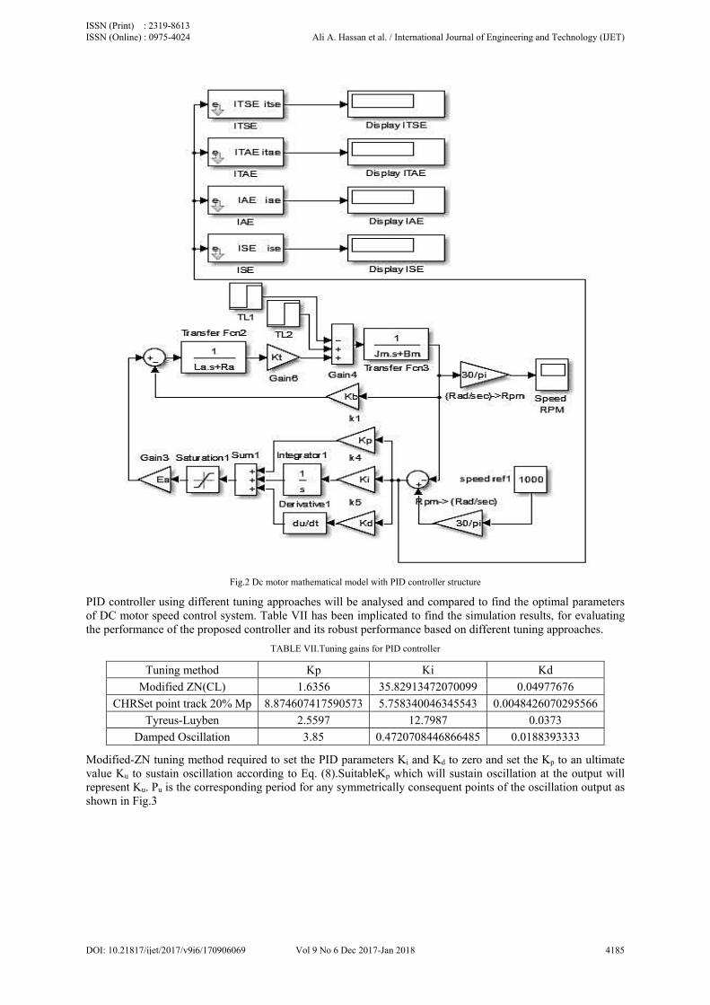
Fig.2 Dc motor mathematical model with PID controller structure
PID controller using different tuning approaches will be analysed and compared to find the optimal parameters of DC motor speed control system. Table VII has been implicated to find the simulation results, for evaluating the performance of the proposed controller and its robust performance based on different tuning approaches.
TABLE VII.Tuning gains for PID controller
Tuning method Kp Ki Kd
Modified ZN(CL) 1.6356 35.82913472070099 0.04977676
CHRSet point track 20% Mp 8.874607417590573 5.758340046345543 0.0048426070295566
Tyreus-Luyben 2.5597 12.7987 0.0373
Damped Oscillation 3.85 0.4720708446866485 0.0188393333
Modified-ZN tuning method required to set the PID parameters Ki and Kd to zero and set the Kp to an ultimate value Ku to sustain oscillation according to Eq. (8).SuitableKp which will sustain oscillation at the output will represent Ku. Pu is the corresponding period for any symmetrically consequent points of the oscillation output as shown in Fig.3
ISSN (Print) : 2319-8613 ISSN (Online) : 0975-4024 Ali A. Hassan et al. / International Journal of Engineering and Technology (IJET)
DOI: 10.21817/ijet/2017/v9i6/170906069 Vol 9 No 6 Dec 2017-Jan 2018 4185

Fig. 3 Critical gain Ku and corresponding ultimate period Pu
The ultimate gain Ku= 8.178, by using the measurement tool in Matlab scope window the corresponding ultimate period has been found Pu=0.0913, then applying these values to Table II to calculate the required PID controller gains. The same procedure could be applied to Tyreus–Luyben tuning method in Table V and damped oscillation tuning method in Table VI. Unlike CHR tuning method, it’s required to find K, L and T, and then to find these required values a step input will be applied to the system. Then inspect the output to measure the required parameters from the curve Fig. 4.
Fig. 4 Step Response Curve for Open Loop
Using the measurement tool in the Matlab scope, the required parameters could be found:
K=101.5, L=0.001161 and T=1.100839, hence KL/T=0.107. Then apply these values to Table III or Table IV to find the required PID controller. A comparison has been made for the proposed PID controller tuning methods by using the given model Fig.2. The simulation results of Modified Ziegler-Nichols Tuning method is shown in Fig. 5. Chien-Hrones-Reswick PID Tuning with Set point track 20% Mp is shown in Fig. 6. Tyreus – Luyben Method is shown in Fig. 7 and Damped Oscillation Tuning Method is shown in Fig. 8.
ISSN (Print) : 2319-8613 ISSN (Online) : 0975-4024 Ali A. Hassan et al. / International Journal of Engineering and Technology (IJET)
DOI: 10.21817/ijet/2017/v9i6/170906069 Vol 9 No 6 Dec 2017-Jan 2018 4186
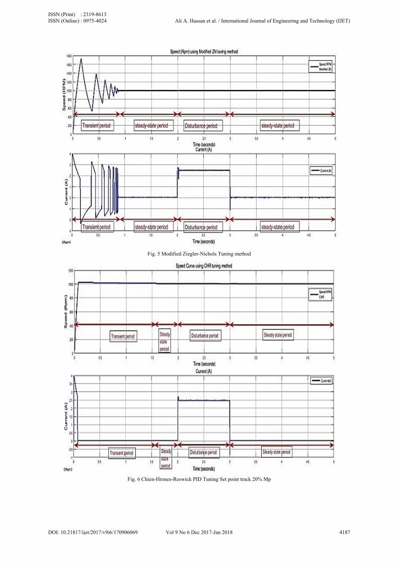
Fig. 5 Modified Ziegler-Nichols Tuning method
Fig. 6 Chien-Hrones-Reswick PID Tuning Set point track 20% Mp
ISSN (Print) : 2319-8613 ISSN (Online) : 0975-4024 Ali A. Hassan et al. / International Journal of Engineering and Technology (IJET)
DOI: 10.21817/ijet/2017/v9i6/170906069 Vol 9 No 6 Dec 2017-Jan 2018 4187

Fig. 7Tyreus-Luyben tuning method
Fig. 8 Damped Oscillation tuning method
The comparison of the overall response results are presented in Table VIII
ISSN (Print) : 2319-8613 ISSN (Online) : 0975-4024 Ali A. Hassan et al. / International Journal of Engineering and Technology (IJET)
DOI: 10.21817/ijet/2017/v9i6/170906069 Vol 9 No 6 Dec 2017-Jan 2018 4188

TABLE VIII.The comparison of the response results
Tuning Method Tr (s) Ts (s) Mp(%) Ess (%) On-load speed(RPM)
Modified- ZN 0.0571 0.874 74.56 0.009 999.991
CHRsetpoint 20% overshoot 0.0583 1.66 1.531 0.002 1002
TyreusLuyben 0.0573 0.714 15.69 0.0012 998.8
Damped Oscillation 0.0578 0.0578 0.02 0.002 1002
Simulation responses represent transient (settling time), steady state, and disturbance of the speed and input current period which shows the response ability of the controller.
In order to analyse, study and comparison the behaviour of the system under different tuning methods is presented in Table IX.
TABLE IX.Performance indices
Tuning method ISE IAE ITAE ITSE
Modified -ZN 871.2 20.54 5.98 173.4 CHR, set point 20%Mp 256.5 7.121 4.978 7.853 Tyreus-Luyben 285.4 7.772 2.327 11.2 Damped oscillation 252.4 4.812 2.721 5.002
VI. PRACTICAL IMPLEMENTATION
Matlab simulink model has been used for tuning of the PID controller which has the parameters as in Table VII. The gains from Table VII have been applied to the practical circuit which consists of microcontroller Atmega328 which has the specifications in [23], PMDC, IBT-2 motor driver that controls the speed by using pulse width modulation (PWM) and tacho-generator which is works as a feedback device that coupled to the motor armature for measuring the actual speed of the motor shaft as shown in Fig. 9. The PMDC motor has the parameters in Table I. Power supply unit has been used to supply the motor with the suitable voltage with the sufficient current. The practical performance can be achieved by made disturbance on the motor shaft under stable condition. Plotting corresponding system responses for each proposed tuning method are presented in Fig. 10 to Fig. 13.
Fig.9 Practical implementation system
ISSN (Print) : 2319-8613 ISSN (Online) : 0975-4024 Ali A. Hassan et al. / International Journal of Engineering and Technology (IJET)
DOI: 10.21817/ijet/2017/v9i6/170906069 Vol 9 No 6 Dec 2017-Jan 2018 4189
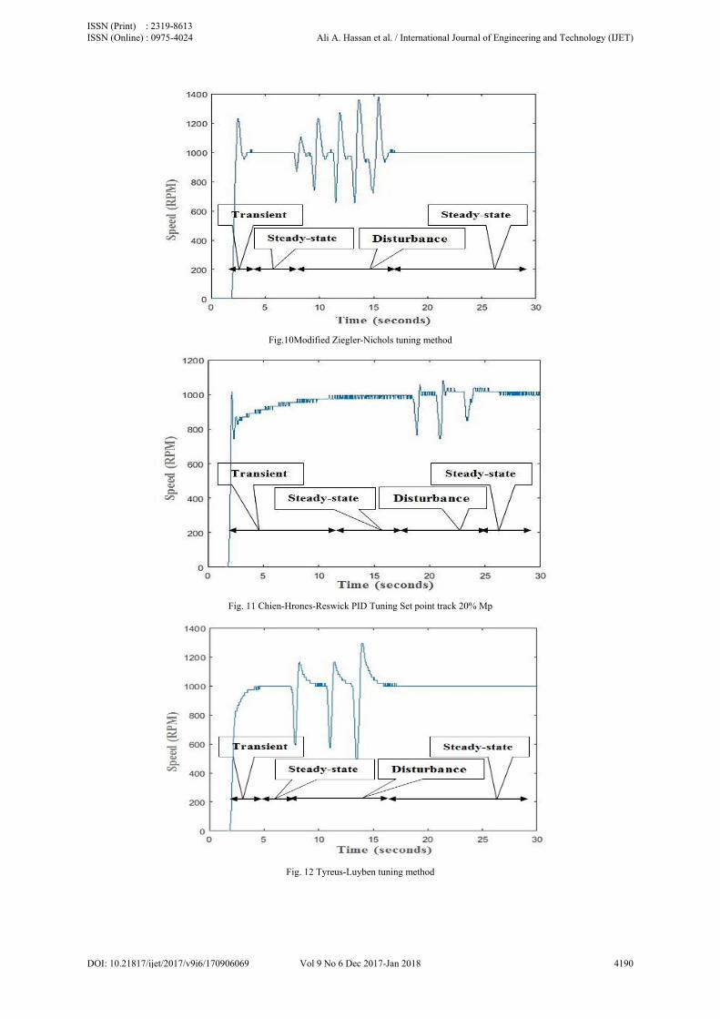
Fig.10Modified Ziegler-Nichols tuning method
Fig. 11 Chien-Hrones-Reswick PID Tuning Set point track 20% Mp
Fig. 12 Tyreus-Luyben tuning method
ISSN (Print) : 2319-8613 ISSN (Online) : 0975-4024 Ali A. Hassan et al. / International Journal of Engineering and Technology (IJET)
DOI: 10.21817/ijet/2017/v9i6/170906069 Vol 9 No 6 Dec 2017-Jan 2018 4190
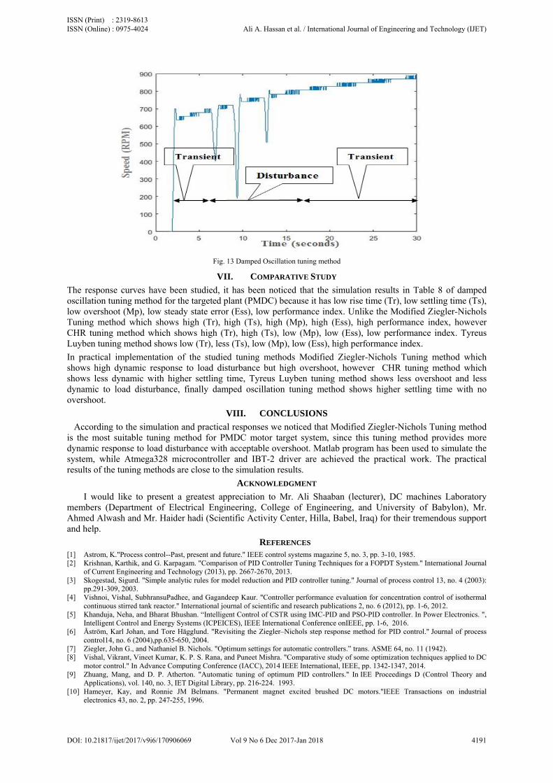
Fig. 13 Damped Oscillation tuning method
VII. COMPARATIVE STUDY
The response curves have been studied, it has been noticed that the simulation results in Table 8 of damped oscillation tuning method for the targeted plant (PMDC) because it has low rise time (Tr), low settling time (Ts), low overshoot (Mp), low steady state error (Ess), low performance index. Unlike the Modified Ziegler-Nichols Tuning method which shows high (Tr), high (Ts), high (Mp), high (Ess), high performance index, however CHR tuning method which shows high (Tr), high (Ts), low (Mp), low (Ess), low performance index. Tyreus Luyben tuning method shows low (Tr), less (Ts), low (Mp), low (Ess), high performance index.
In practical implementation of the studied tuning methods Modified Ziegler-Nichols Tuning method which shows high dynamic response to load disturbance but high overshoot, however CHR tuning method which shows less dynamic with higher settling time, Tyreus Luyben tuning method shows less overshoot and less dynamic to load disturbance, finally damped oscillation tuning method shows higher settling time with no overshoot.
VIII. CONCLUSIONS
According to the simulation and practical responses we noticed that Modified Ziegler-Nichols Tuning method is the most suitable tuning method for PMDC motor target system, since this tuning method provides more dynamic response to load disturbance with acceptable overshoot. Matlab program has been used to simulate the system, while Atmega328 microcontroller and IBT-2 driver are achieved the practical work. The practical results of the tuning methods are close to the simulation results.
ACKNOWLEDGMENT
I would like to present a greatest appreciation to Mr. Ali Shaaban (lecturer), DC machines Laboratory members (Department of Electrical Engineering, College of Engineering, and University of Babylon), Mr. Ahmed Alwash and Mr. Haider hadi (Scientific Activity Center, Hilla, Babel, Iraq) for their tremendous support and help.
REFERENCES [1] Astrom, K."Process control--Past, present and future." IEEE control systems magazine 5, no. 3, pp. 3-10, 1985. [2] Krishnan, Karthik, and G. Karpagam. "Comparison of PID Controller Tuning Techniques for a FOPDT System." International Journal
of Current Engineering and Technology (2013), pp. 2667-2670, 2013. [3] Skogestad, Sigurd. "Simple analytic rules for model reduction and PID controller tuning." Journal of process control 13, no. 4 (2003):
pp.291-309, 2003. [4] Vishnoi, Vishal, SubhransuPadhee, and Gagandeep Kaur. "Controller performance evaluation for concentration control of isothermal
continuous stirred tank reactor." International journal of scientific and research publications 2, no. 6 (2012), pp. 1-6, 2012. [5] Khanduja, Neha, and Bharat Bhushan. “Intelligent Control of CSTR using IMC-PID and PSO-PID controller. In Power Electronics. ",
Intelligent Control and Energy Systems (ICPEICES), IEEE International Conference onIEEE, pp. 1-6, 2016. [6] Åström, Karl Johan, and Tore Hägglund. "Revisiting the Ziegler–Nichols step response method for PID control." Journal of process
control14, no. 6 (2004),pp.635-650, 2004. [7] Ziegler, John G., and Nathaniel B. Nichols. "Optimum settings for automatic controllers.” trans. ASME 64, no. 11 (1942). [8] Vishal, Vikrant, Vineet Kumar, K. P. S. Rana, and Puneet Mishra. "Comparative study of some optimization techniques applied to DC
motor control." In Advance Computing Conference (IACC), 2014 IEEE International, IEEE, pp. 1342-1347, 2014. [9] Zhuang, Mang, and D. P. Atherton. "Automatic tuning of optimum PID controllers." In IEE Proceedings D (Control Theory and
Applications), vol. 140, no. 3, IET Digital Library, pp. 216-224. 1993. [10] Hameyer, Kay, and Ronnie JM Belmans. "Permanent magnet excited brushed DC motors."IEEE Transactions on industrial
electronics 43, no. 2, pp. 247-255, 1996.
ISSN (Print) : 2319-8613 ISSN (Online) : 0975-4024 Ali A. Hassan et al. / International Journal of Engineering and Technology (IJET)
DOI: 10.21817/ijet/2017/v9i6/170906069 Vol 9 No 6 Dec 2017-Jan 2018 4191

[11] Glowacz, Zygfryd, and Antoni Zdrojewski. "Mathematical modelling of commutator DC motor in failure conditions." In Diagnostics for Electric Machines, Power Electronics and Drives, 2005. SDEMPED 2005. 5th IEEE International Symposium on, IEEE, pp. 1-5, 2005.
[12] Galijašević, Sanel, ŠemsudinMašić, SenadSmaka, AbdulahAkšamović, and DinkoBalić. "Parameter identification and digital control of speed of a permanent magnet DC motors." In Information, Communication and Automation Technologies (ICAT), 2011 XXIII International Symposium on, pp. 1-7. IEEE, 2011.
[13] A. Maria, "Introduction to modeling and simulation studies. ",Proc. of the 1997 Winter Simulation Conf. Atlanta, GA, pp. 7-13, Dec. 7-10, 1997.
[14] Payakkawan, Poomyos, KitdakornKlomkarn and PitikhateSooraksa. “Dual-line PID controller based on PSO for speed control of DC motors.” 2009 9th International Symposium on Communications and Information Technology, pp134-139, 2009.
[15] Babu, Reshma, and R. Swarnalath. "Comparison of Different Tuning Methods for pH Neutralization in Textile Industry." Journal of Applied Sciences17, pp. 142-147, 2017.
[16] Shahrokhi, Mohammad, and AlirezaZomorrodi. "Comparison of PID controller tuning methods.” Department of Chemical & Petroleum Engineering Sharif University of Technology (2013).
[17] Copeland, Brian R. "The Design of PID Controllers using Ziegler Nichols Tuning." Journal of Intelligent & Robotic Systems 11, no. 15, pp. 121-127, 2008.
[18] Sheel, Satya, and Omhari Gupta. "New techniques of PID controller tuning of a DC motor—development of a toolbox." MIT IJEIE 2, no. 2, pp. 65-69,2012.
[19] Luyben W.L, M.L. Luyben;Essentials of Process Control: McGraw-Hill, 1997. [20] MURRILL, PW, P. D. SCHNELLE JR, BG LIPTÁK, J. GERRY, M. RUEL, and FG SHINSKEY. Instrument Engineers' Handbook,
(Volume 2) Third Edition: Process Control,pp. 414- 431. [21] Raut, Kiran H., and S. R. Vaishnav. "Performance Analysis of PID Tuning Techniques based on Time Response specification."
International Journal of Innovative Research in Electrical, Electronics, Instrumentation and Control Engineeringvol. 2, issue 1, january 2014.
[22] Das, Saptarshi, Suman Saha, Shantanu Das, and Amitava Gupta. "On the selection of tuning methodology of FOPID controllers for the control of higher order processes." ISA transactions 50, no. 3, pp 376-388,2011.
[23] Datasheet of Arduino Uno, "Arduino UNO" Available in the Site https://www.arduino.cc/en/main/arduinoBoardUno, 2017.
ISSN (Print) : 2319-8613 ISSN (Online) : 0975-4024 Ali A. Hassan et al. / International Journal of Engineering and Technology (IJET)
DOI: 10.21817/ijet/2017/v9i6/170906069 Vol 9 No 6 Dec 2017-Jan 2018 4192


![Armature Voltage Speed Control of DC Motors Based Foraging ...aeuso.org/.../Vol5_Iss14_1940...Speed_Control_of_D.pdf · control etc. [1].DC motors provide excellent control of speed](https://img.dokumen.tips/doc/110x75/5e7b1d6831d1dc7a7e5a6044/armature-voltage-speed-control-of-dc-motors-based-foraging-aeusoorgvol5iss141940speedcontrolofdpdf.jpg)


