Embed Size (px)
Citation preview

e~
Z
MINISTRY OF AVIATION
lOYAl. AfRCRAeT. ~ST~gkrSl,,t~l~,~
~FORD.
AERONAUTICAL RESEARCH COUNCIL REPORTS AND MEMORANDA
R. & M. No. 3488
Comparative Numerical Applications Reverse-flow Theorem to Oscillating
and Control Surfaces
of the Wings
By Doris E. Lehrian, B.Sc., and H. C. Garner, M.A., A.F.R.Ae.S., F.I.M.A.
L O N D O N : HER MAJESTY'S STATIONERY OFFICE
1967
.PRICE 18s. 0d. NET

Comparative Numerical Applications Reverse-flow Theorem to Oscillating
and Control Surfaces
of the Wings
By Dor i s E. Lehr ian , B.Sc., a n d H. C. G a r n e r , M.A. , A . F . R . A e . S . , F . I . M . A .
6 Reports and Memoranda NO. 3488 August, 1965
Summary.
The reverse-flow theorem gives alternative integrals for generalized forces on oscillating wings by linearized theory. Applications to analytical and numerical solutions are discussed, and the latter are considered in some detail. Reverse-flow relations for plunging and pitching derivatives are formuiated in terms of those for the reversed wing, and the accuracy of numerical solutions is examined thereby for wings having streamwise symmetry or mote general planform. The further relations required in the application of the reverse-flow theorem to cases of low frequency are given, and these formulae for the reversed wing are adapted to Multhopp's lifting-surface theory. Finally, for general frequency, treatment of oscillating control surfaces by smooth equivalent upwash functions is considered by means of reverse flow, with particular reference to rectangular wings with full-span controls.
The various applications of the reverse-flow theorem are illustrated by calculated examples for a range of Mach number, frequency, wing planform and control surface. No firm conclusions regarding absolute accuracy are possible, nor can a preference be stated between numerical results by direct flow and reverse flow. Simple indications of inaccuracy due to inadequate collocation are illustrated. Convincing com- parisons between the alternative calculations are found in most examples, and these include lift and pitch- ing moment due to slowly oscillating part-span control surfaces on delta and arrowhead wings.
Section
1.
2.
3.
4.
LIST OF CONTENTS
Introduction
Oscillating Wings in Direct Flow
Reverse-Flow Theorem
Applications to Finite Frequency
4.1 Generalized forces on wings
4.2 Plunging and pitching derivatives
4.3 Equivalent upwashes for control surfaces
*Approved on behalf of Director, N.P.L. by Dr. R. C. Pankhurst, Superintendent of Aerodynamics Division.
Replaces A.R.C. 27166. ~ ('~t... t~-_~"c~ ~ . [ ~ " • i i [o(~

LIST OF CONTENTS--cont inued
. Applications to Low Frequency
5.1 Pitching wings
5.2 Control surfaces
. Numerical Comparisons
6.1 Results for pitching wings
6.2 Results for control surfaces
7. Concluding Remarks
8. Acknowledgements
List of Symbols
References
Tables 1-4
Figures 1-20
1. Introduction. The existence of relationships between the overall aerodynamic characteristics of wings in direct flow
and reverse flow was demonstrated initially for certain planforms in steady supersonic flow. Flax (Ref. 1, 1952) reviewed earlier work and derived general reverse-flow theorems, valid within the limits of linearized lifting-surface theory, for any wing planform in either subsonic or supersonic steady flow. The extension to non-stationary compressible flows soon followed in Refs. 2 and 3. The reverse-flow theorem for simple harmonic motion, presented by Flax (Ref. 2, 1953), was used to determine relations between certain aerodynamic force coefficients in direct and reverse flows; furthermore these coefficients for any wing with arbitrary deformation were expressed in terms of solutions for the wing in reverse flow with simple modes of oscillation. More general reciprocal and reverse-flow theorems for arbitrary time-dependent motions were established by Heaslet and Spreiter (Ref. 3, 1953); in particular, they deduced surface-integral relations for various aerodynamic forces on wings in steady or indicial motion with arbitrary twist, camber or control-surface deflection.
Attention is now restricted to the use of the reverse-flow theorem for oscillatory motion. An interesting application is to the reformulation of the flutter problem for low-aspect-ratio wings in compressible flow 4. A more typical example of the theorem's use is in the exact calculation of generalized forces on an oscillat- ing delta wing witti supersonic edges s. The reverse-flow approach is particularly effective for wings with unswept trailing edges and is used in the development of a numerical box-grid method for subsonic flow a. For wings of general planform, both the direct-flow and reverse-flow solutions are subject to the approxi- mations of a particular box-grid or collocation method. Differences between these solutions do not necessarily indicate the extent of the approximations, but the comparisons are often instructive.
The present report states the reverse-flow theorem and gives alternative expressions for oscillatory generalized forces (Section 3). For plunging and pitching motion the aerodynamic forces are related to those of the reversed wing (Section 4.2). Special attention is given to slow pitching oscillations when reverse-flow relations are derived to first order in frequency (Section 5.1). Results for various planforms by various methods are presented in Section 6.1. The emphasis is on numerical solutions for subsonic flow; few calculations by reverse flow are available for general frequencies of oscillation, but there are more systematic results for low frequency and steady motion.

The lift and pitching moment on a wing with oscillating control surface are treated as a particular case of the reverse-flow relations in Section 4.1. Collocation methods in subsonic flow include the alter- native approach in which a smooth equivalent upwash function replaces the discontinuous boundary condition in direct flow. Davies (Ref. 7, 1963), constructs equivalent upwashes to represent any oscillating part-span control by use of the reverse-flow theorem. Section 4.3 gives a simple presentation of his treatment and considers an adaptation suited to a particular lifting-surface method s for general fre- quencies. The case of low frequency is briefly discussed in Section 5.2. Illustrative examples are given for various wing and control-surface configurations in subsonic flow corresponding to steady motion, low or finite frequency (Section 6.2).
2. OscilIatin9 Vl~ngs in Direct Flow. Oscillatory lifting-surface problems in an incompressible or a compressible airstream are usually
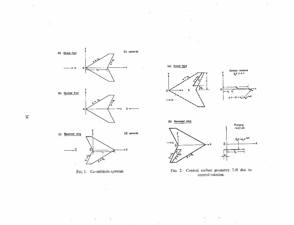
solved by methods based on linearized theory. This implies that the problem can be approximated to that of a thin wing oscillating with small amplitude in a uniform, inviscid stream. A system of rectangular co-ordinates (x,y,z) with the free-stream velocity U in the direction of the positive x-axis is used in Fig. la for the problem in direct flow. In its mean position in the plane z = 0 the wing planform is symmetrical about the x-axis with the leading edge of its root chord at the origin of co-ordinates.
For simple harmonic oscillations of frequency e), the upward deflection of the wing from the plane z = 0 is represented in complex notation as
z(x,y,t) = zj(x,y) bj e ~0'~, (1)
where b i is the amplitude of oscillation and the suffixj indicates an arbitrary mode of oscillation which may be either rigid or flexible, continuous or discontinuous. The upwash distribution w(x,y,t) over the wing surface must satisfy the tangential flow condition given by
Oz v OZ w(x,y,t) = - ~ + Ox
= [ i o o z / x , y ) + U ~ - - ~ z / x , y ~ b ~ e ~'
= w~(x,y) bj e i~t, say. (2)
The corresponding load distribution Ap(x,y,t) over the wing is
Ap(x,y,t) = ½p U z l(x,y,t), (3)
where l(x,y,t) = 1/x,y) bj e i'°t.
For a non-dimensional displacement modef(x,y) the generalized aerodynamic force can be expressed as
F O R C E = I f f ( x , y ) A p ( x , y , t ) d x d y ~UzS "~ b e~,~t = t' ~zi~ ~ , (4) S
whence the non-dimensional force coefficient is
Q~J - 2S (x,y) l~(x,y) dx dy. (5) S

In order to determine the load distribution, it is necessary to solve an integral equation relating wj(x,y) and lj(x,y). Analytical solutions are only possible for special planforms in incompressible or supersonic flow. For general wing planforms there are many numerical techniques for subsonic, sonic and supersonic ranges of Mach number. Various methods for subsonic flow are discussed in Ref. 9; similarly Refs. 10 and 11 review the theoretical treatments available for sonic and supersonic flow respectively. For the purposes of this report, there is no need to consider the details of the different lifting-surface methods.
3. Reverse-Flow Theorem. For a lifting surface in simple harmonic motion Flax establishes a reverse-flow theorem valid for
subsonic and supersonic flow within the limits of linearized theory 2. The theorem gives a general relation between one solution in direct flow and another solution for the same wing planform in reverse flow. Here the oscillatory motions must have the same frequency, although the modes of oscillation will in general be different ;" the free-stream Mach numbers are the same in direct and reverse flow.
The lifting-surface problem and notation in direct flow are outlined in Section 2 where the free-stream velocity is of magnitude U in the direction of the positive x-axis (Fig. la). The reverse flow has a free- stream velocity of - U in the direction of the positive x-axis (Fig. lb); the planform edge x = x~ now acts as a trailing edge subject to the Kutta condition, while the planform edge x = x~ has the singularity in load distribution appropriate to a leading edge. In reverse flow, consider a harmonic motion defined by the wing deflection Z(x,y,t) and the frequency of oscillation ~, so that the upwash distribution W(x,y,t) over the wing planform must satisfy the condition
8Z 8Z w(x,y,t) = - i f - v ~-£.
Then, the reverse-flow theorem 2 states that the corresponding load distribution AP(x,y,t) over the plan- form satisfies the equation
S S
where S is the area of the wing planform and w(x,y,t) and Ap(x,y,t) correspond to any wing deflection mode in direct flow as defined in Section 2. For prescribed modes of oscillation in direct and reverse flow these integrals can be interpreted as overall force coefficients and hence this equation provides a useful technique for simplifying certain lifting-surface problems.
It is not necessary to specify an actual deflection mode for the oscillatory motion Z(x,y,t) of the wing in reverse flow. If the upwash distribution W(x,y,t) is identified with the displacement mode of the generalized force in direct flow, then equation (6) gives an expression for this force in terms of the load distribution AP(x,y,t) over the wing in reverse flow. Take
W(x,y,t) = Wi(x,y) e i°~t = U ~(x,y) ei~t ; (7)
then, as in equation (3), the corresponding load distribution can be written as
AP(x,y,t) = ½pUZ L~(x,y)e i'°' (8)
and equation (6) becomes
S S
(9)
For the wing in direct flow let
w(x,y,t) w j ( x , y ) b j e ic°t iwt = = UFj(x,y) bj e . (10)
The generalized force coefficient in direct flow, as defined by equations (3) and (5), can therefore be expressed as
Qij = l l f Fi(x,y) L~(x,y) dx dy, (11)
S
where by equations (2) and (10)
ico 0 Fj(x,y) = -g- zj(x,y) + 7x zj(x,y). (12)
Thus, in general, the force coefficient Q.ij can be determined from equations (11) and (12) by means of the solution L~(x,y) for the wing in reverse flow corresponding to the upwash distribution W~(x,y) of equation (7).
Evaluation of the force coefficient Q~ by the reverse-flow equation (t 1) is often effected by using solutions for the 'reversed wing' in direct flow (Fig. lc), and it is useful to interpret equations (7) and (11) accordingly.
Consider a second wing in direct flow, whose planform is unspecified initially, then a lifting-surface solution for this wing is defined by equations (1) and (5). In order to distinguish this solution from the original wing problem, replace (id) by (p,q) to define the modes of oscillation and insert a bar over all other quantities. Thus, a generalized force coefficient corresponding to modes (p,q) and a frequency of oscillation c5 in a direct flow U will be defined for the second wing as
~pq = l Iff~(~Y,y) ,q(~,~) d~ d~, (13)
S
where the non-dimensional loading 7q(2,y) bq e ~t corresponds to an upwash distribution ~q(~,y) bq e i~'. The second wing is now identified with the 'reversed wing', and so S = S. The co-ordinates (~,~,~) of this wing problem (Fig. lc) are related to the original co-ordinates (x,y,z) by
,2 = c , - x , y~ = - y , ~ = z. (14)
Taking N = co and U - - U as required by the reverse-flow theorem, we express the solution for the original wing in reverse flow in terms of solutions for the 'reversed wing' in direct flow. The upwash in reverse flow from equation (7) can be expressed as
w~(x,y) = ~ Aii %(x,$), (15) q
so that the corresponding load distribution over the wing in reverse flow is
Li(x,y) = ~ Aiq.7,~(-~,$). (16) q
Furthermore, equation (12) can be expressed as
F~(x,y) = ~ BjpL(x,y). P
(17)

In equations (15) to (17) the coefficients Aiq, Bjp will be functions of frequency on. By equations (14), (16) and (17) the generalized force coefficient in equation (1 1) becomes
S
21S p q I f - - dx dy, = - - ~ ~ BjpA~q L(~,~)I~(~,~) S
and by equation (13)
Q~J = Z ZAi. Bj. 0... (18) P q
Thus, the generalized force coefficient Q~j is obtained as a linear combination of the generalized force coefficients Qpq appropriate to the 'reversed wing' in direct flow.
If the wing planform is symmetrical about a spanwise axis, the 'reversed wing' is identical to the original. Equation (18) then provides the identity
Q~J = Z Z Aiq B~p Qpq (19) P q
between the generalized force coefficients corresponding to different modes of oscillation.
4. Applications to Finite Frequency. The reverse-flow relations in Section 3 apply to any force displacement mode fi(x,y) or upwash mode
wj(x,y), whether continuous or discontinuous. Only continuous modes are now considered forfi(x,y) as illustrated in Section 4.1. A particularly useful application is to a discontinuous mode wj(x,y); at subsonic speeds the transformed problem in reverse flow is then more easily solved. In Section 4.2, we derive relations between the plunging and pitching derivatives of a wing and their values for the reversed wing; these provide useful indications of errors incurred in numerical solutions. In obtaining collocation solutions for part-span control surfaces in subsonic flow it is often expedient to replace the discontinuous upwash wj(x,y) by an equivalent smooth distribution of upwash. Davies 7 has developed this procedure in considerable generality with the aid of the reverse-flow theorem. Section 4.3 considers his treatment in its simplest form and dxscusses its field of application; a modified equivalent upwash, more appropriate to Ref. 8, is suggested.
4.1. Generalized Forces on Wings. A generalized force coefficient QCj, for which the displacement mode f~(x,y) is a smooth continuous
function, can be determined by the reverse-flow theorem for an arbitrary mode of oscillation zj(x,y ). To illustrate this, the application to lift, pitching moment and rolling moment is considered. The non- dimensional displacement modes are defined as
i = 1, A ( x , y ) = 1 .]
i = 2, A(x,y) = x/kt '
i = 3, f z ( x , y ) = y/k
(20)

where k is a representative length of the planform. Then, by the following definitions and equation (4),
L=Lif t=IIApdxdy=pUZSQ1jb3ei~t S
~ ' = Pitching moment about the y-axis
= - f f x Ap dx dy = - p U 2 Sk Q2i bj e i~t S
= Rolling moment about the x-axis
=f lyApdxdy=pU2Sk(2a , bjd~ S
(21)
The generalized coefficients Qij are evaluated from equation (11), viz.,
Qo=lfIF~(x,y)Li(x,y)dxdy, S
(22)
where from equations (10) and (12)
_ w j _ i¢ozj azj Fj(x,y) U U+~Tx"
The load distributions Li(x,y) over the wing in reverse flow correspond to the simple upwash distributions Wi(x,y) from equations (7) and (20)
3 wl(X,y) = u |
W2(x,y) = Ux/k
W3(x,y) = Uy/k
(23)
Hence from equations (21) and (22) the forces L, J~ and ~o on the wing for any oscillatory mode z~(x,y) are obtained quite generally as integral expressions of relatively simple solutions for the wing in reverse flow. For example, Fig. 2 illustrates how the lift due to an oscillating control surface in subsonic flow can be determined without resort to special treatment of the discontinuous boundary condition for wj(x,y).
4.2. Plunging and Pitching Derivatives. To elucidate further the application of the reverse-flow theorem, the specific rigid modes of oscillatory
plunging (j = 1) and pitching (j = 2) are considered. These motions are defined by equation (1) with
Zl = -k , bl = zo/k l (
z = = - x , b2 Oo J (24)
7

where z o and 00 are respectively the amplitudes of the plunging and pitching motion. Reverse-flow relations for the lift and pitching moment are obtained from equations (21) by inserting in equation (22) the appropriate function zj(x,y) from equations (24), that is to say
F l ( x , y ) = __wl = - i v U
W 2 i v x F2(x,y) = ~ - = - 1 - ~ -
(25)
where the frequency parameter v = ook/U. To evaluate these forces, reverse-flow solutions are required for the upwash distributions W, and WE of equations (23). These are written in the form of equation (15), so that
Wl(x,y) = u = All ~ (~ ,y )
Wz(x,y)- U(c~-~) k - Az I~ (~Y 'Y )+A='22 (x 'Y )
(26)
where the co-ordinates (~,y) are defined in equation (14). The bar over any symbol refers that quantity to the reversed win9 in direct flow. Thus the upwash distributions ~q(~,y) for q = 1 and 2 correspond to plunging and pitching oscillations respectively, so that
~1 (~,Y) = u ( - iv)
~2(x,y) = U(-1-i~ -~) (27)
Therefore the coefficients Aiq in equation (26) are
A21. = v~q-~
A22 -~ - - i/V )
Similarly, the functions in equation (25) can be written in the form of equation (17), so that
Fl(x,y) = -- iv = B l l fl(x,Y) ]
F2(x ,y /= - 1 - iv ~ - g - / = B2, f l (~ ,y /+ B = f2(x,y) \ /
where analogous to equations (20)
fl(x,y) = 1 [ .
J f~(x,y) = ~/k
(28)
(29)
(30)

The.coefficients Bjp in equations (29) are therefore
B l l = - i v
B2i = - - 1 - - i v
B 2 2 = iv
(31)
Relations between the force coefficients Qii (i = 1,2 and j = 1,2) on a wing in direct flow and the force coefficients ~9 pq (p = 1,2 and q = 1,2) on the reversed wing in direct flow can be deduced immediately; with the coefficients Aiq and Biq from equations (28) and (31) and A12 = BI2 = 0, equation (18) becomes
Q II ~ QII
Q~ = -Q2~+ Lk vJ Q~
Li - -~ j 2+02 + Lk d o ' '
(32)
The last two relations may be replaced by
b ,l b ,l } Q~- L-E-U Q2, = Q2z- L~-U O2,
(33)
For a combination of plunging motion and pitching about an axis x = Xo we replace equation (24) by
"5 z l = - k , bl = (Zo-OoXo)/k I
z 2 = - -x , b 2 = 0 o
(34)
By equations (21) and (34)
~ ' = Pitching moment about the axis x = x 0 (35)

In the notation of aerodynamic derivative coefficients for plunging and pitching oscillations
L=pU2S~_lz+iV(~)(~)+(lo+ivio)Oole~,t. " z° t '
Jl=pU2SkI(mz+~Vm~)(~)+(mo+ivmo)Oolei~
where v = o)k/U. Equations (35) and (36) give the identities
l~+ivl~ = Q l l
X0 lo+ivlo = Q i 2 - ~ - Q l l
XO --m~-ivme = Q2i-~-Qll
X 0 X(2 "~ 2 -mo-ivmo = Q z 2 - ~ - ( Q 1 2 - t - Q 2 1 ) - } - ~ - ~ - ) Qll
(36)
(37)
for the wing in direct flow. The last two relations may be replaced by
(mz+ivm)+(lo+ivlo) = Q i 2 - Q 2 i ~ .
m° )+ Xo (lo+ivlo)= Xo (38)
The identities in equations (37) and (38) are applied to the reversed wing by placing a bar over all quantities, except v and k. The identities for (l z + iv 7) and ( ~ + iv ~) together with the first two relations in (32) and in (37) combine to give the lift derivatives in direct flow,
l:~ ~ 7 Z
[ cr- xo- ~o) lo =~z+~ ~ 7z+7~
Cr
; (39)
these are derived by eliminating Q i l, Q12, 0`11 and 0.21 and equating real and imaginary parts. Expressions for the pitching moment derivatives in direct flow involve the additional equations (33), (38) and the corresponding relations for the reversed wing. With some manipulation it can be shown that
10
' mz +lo =m~+70 .
m~ + Io = ~ +7o
( c,-xo-~o~. " = ~ 0 + c, x~ x0 mo+k-----~--'-)to+l o ( ) .7o+7 o .. (40)
. 1, 17 ..o. t t- 9 ' ° - 7 °
In equations (39) and (40) the pitching axis 2 = Xo for the reversed wing is independent of the pitching axis x = x 0 of the original wing motion. Although these axes are arbitrary, the relations in equation (40) exhibit a symmetrical form.
For a wing planform which has a spanwise axis of symmetry, the reversed wing is the same as the original wing and the corresponding derivatives are identical when 20 = Xo. It follows from equations (39) and (40) that the plunging and pitching derivatives for an axis x -- Xo satisfy two non-vanishing relations
l o = m , + ( ~ ) l z + l ~ (41)
For small values of v ~ 1, the terms in equations (39) and (40) of O(v -2) will introduce errors into the evaluation of some of the derivatives in direct flow, unless sufficient significant figures are retained in the derivatives for the reversed wing. It would be better to use solutions for the reversed wing which correspond to W 1 and W2 of equation (23) with x = c r -£ . This procedure must be considered for the limiting case v~O (Section 5.1).
4.3. Equivalent Upwashes for Control Surfaces. The deflection mode zj(x,y) of a part-span control will have spanwise discontinuities at y -- Ya, and its
slope OzHOx will be discontinuous along the hinge line x = xa(y ) at the leading edge of the control surface (Fig. 2a). When the force mode f~(x,y) is continuous the reverse-flow relation of equation (11) can be used to evaluate Qu; for example, the lift and pitching moment can be determined from equation (21) by using the reverse-flow solutions Li(x,y), i = 1,2 respectively and evaluating the integrals over the control-surface area C. For trailing-edge controls, the integration of Li(x,y) will involve the loading near the singularity at the leading edge, the region where subsonic lifting-surface theories are least reliable. With collocation methods of solution it can be advantageous to convert the problem into one in direct flow with smooth equivalent upwashes to replace the discontinuous upwash wj(x,y).
Davies v has given a general basis for contructing equivalent upwash functions to represent an oscillating part-span control surface on a wing of arbitrary planform in subsonic flow. It may be helpful to set down the essential formulae irrespective of collocation method. We now denote a discontinuofls mode by j = d in equation (1); typically zfix,y) = 0 off the control surface. By the reverse-flow relation of equation (11) the generalized force coefficient is
Qij = l IfFs(x,y) Li(x,y) dx dy, S
(42)
where Fi~ a-]
11

It is required to replace the discontinuous function Fj(x,y) in equation (42) by a continuous function F~r(x,y) of the form
N - 1 M - 1
F~,(x,Y'= S 2 E j . . , g n ( ~ ) h . , ( Y ' ~ \U' n = O m = O
(43)
where g. and h m a r e polynomials of degree n and m respectively, k is the representative length, and Ejnm are unknown coefficients : thus equation (42) becomes
Qis = l f IF~(x,y) Li(x,y) dx dy. S
(44)
Then, transformation back to direct flow by means of the reverse-flow relation of equation (9) gives
QiJ = ~--~IIf~(x,y) lJ(x,y) dx dy, S
(45)
where the non-dimensional loading l~(x,y) corresponds to the equivalent upwash w~(x,y) = U F~(x,y) over the wing in direct flow, and the coefficients Ejnra in equation (43) are to be determined.
Since fdx,y) is continuous, the loading L~(x,y) in reverse flow is represented by a series
R - - 1 S - 1
Li(x,Y) = [ 2 Eair, ~,(#) ~,(rl)] ( ~ ) -~(l - tl2) ¢ r = O s = O
(46)
where Wr and f~s are polynomials of degree r and s respectively, and
_ - - , x -,_,x,(y) tl = -Y • (47) cry) s
this series gives the correct form of loading over the planform in reverse flow, so long as x~(y) and c(y) are taken to be smooth functions of y. The coefficients E j n m of equation (43) can be determined by identifying the terms in equations (42) and (44) for each coefficient a~rs in the expression for Li(x,y ). It is convenient to choose R = N and S = M in equation (46), so that the NM coefficients E j,,,. can be determined from the set of linear simultaneous equations
N - 1 M - I
2E[E'" ' f fg"(k) h'(k)~r(()f~(rl)(l~--~) ¢(1-@)¢dxdy] n = O m = O S
\ i - ~7 S
{r = O , 1 . . . ( R - 1 ) ; s = 0 , 1 . . . ( S - 1 ) } . (48)
12

However, if N or M is small, there is the practical alternative of taking R > N or S > M and obtaining a least squares solution of (48). It is noted that Fs(x,y) is a linear function of the frequency parameter v = oJk/U. If the polynomials 9,(x/k) and hm(y/k) in equation (43) and ~(~) and f~(r/) in equation (46) are real and independent of frequency, it follows that the coefficients Ej,,, and hence the equivalent upwash w}(x,y) will be a linear function of v and independent of the subsonic Mach number.
In Section 8 of Ref. 7, Davies develops this treatment and replaces equation (43) by the function
N - 1 M - 1
k F~(x,Y)=~fi-)ZZEJ,,,~,(~)f~m(r/),
n = 0 m = 0
(49)
where ¢ and r/are defined in equation (47). The polynomials W,(~) and f~m(r/) are identified with Wr(~) and f~s(r/) of equation (46). Further, he takes Wr(~) as a polynomial of degree r which is orthogonal* with respect to the weight function ~/(1 -~)~ over the range 0~< ~ ~< 1. By Appendix III of Ref. 7
cos(r+~)O 'er(~) = (~)*cos½d' (50)
where 1 - ~ = 2!(1-cos 0) for the wing in reverse flow; then
1
~P,(~) ~F,(~) d~ = 0 when n #
0
= 1 when n = r
(51)
Similarly, f~s(r/) is a polynomial of degree s which is orthogonal* with respect to the weight function (1 2± __ r/ )2 over the range -- 1 ~< r/~< 1 ; thus
sin(s + 1)¢ f~,(r/) = @a)}sin~ b , (52)
where q = cos qS, and then
1 1 I f~m(r/) f~s(r/) (1 - r/2) "~ d r /= 0 when m # s
- 1
= 1 when m = s
(53)
*C. Lanczos : Applied Analysis. Pitman & Sons, Ltd., 1957. See Sections 16 to 21 of Chap. V for a discussion of orthogonal function systems and the Jacobi
polynomials.
13
Now, if equation (46) with R = N and S = M is inserted into the identity given by equations (44) and (49) and equation (42), and the variables of integration are changed to (~,t/) of equation (47), we obtain the set of equations
N - 1 M - 1 11
n = 0 m = 0 - 1 0
*(1 - rt2) } d{ dr/1
1 1
- 1 0
{r = 0 , 1 . . . ( N - l ) ; s = 0 , 1 . . . ( M - l ) } .
It follows immediately from the orthogonal relations of equations (51) and (53) that the left-hand side of theseNM equations reduces to E}rs. Hence the required coefficients are
E~Jnm
11
I~c-~-'F j(~,q) ~tln(~) ~,n(rl) ( ~ ) ~(.1-172)~ d~ d~l, - l o
{n = 0 , 1 . . . ( N - l ) ; m = 0 , 1 . . . ( M - l ) } . (54)
Values of the equivalent upwashes w~, = UF~(x,y) can be determined from equations (49) and (54) for particular collocation positions (x,y).
The simplest application of equation (54) is to a rectangular wing with oscillating full-span control of constant chord ratio E. In this case Fs is a function of x only, defined by
F s = 0 for . 0~<~<(1-E) [ , / .
= - [ l + i v ( ~ - l + e ) ] for ( 1 - E ) ~ 1
where v = coc/U and ~ = x/c. With k = c, equation (54) becomes
1 1
s ~ 2 e~... - n.~(,7)(1-~ )2 & [ l + i v ( ~ - l + E ) ] %(0 a~; - 1 1 - E
by equation (52)
1
Ej. o = - (½re) ~- [1 + iv(~- 1 ~ E)] ~=(~) ~ d~
1-E
E).,. = 0for m>~l
(55)
14

Hence, by equation (49), the equivalent upwash is
N - 1
we, = UF~, = U Z ( ½ ~ ) - ~ , ( ~ ) E ' s , o
n = 0
N-- I 1
n = 0 1 - - E
(56)
which is independent of spanwise position y. The same forrhula is obtained if we use equation (43) for the equivalent upwash. For non-rectangular wings, however, this is not the case because the parameter
in equation (47) is then a function ofx and y. When the planform has a central kink, the use of equation (49) may be criticized on the grounds that ~ has corresponding kinks in the (x,y) plane. Thus, when applied to a constant-chord swept wing with full-span control of constant E, Davies' treatment would would lead to an equivalent upwash of identical form to equation (56) with ~ = Ix-xl(y)]/c; w~,(x,y) would be a continuous but not a smooth function across y = 0. This drawback is avoided if equation (43) is used, with the coefficients Es, m determined by equation (48), and this alternative equation would seem to be a better, if less convenient, representation of the equivalent upwash on kinked planforms.
It should be noted that any representation based on the form of loading in equation (46) may be inconsistent with the details of a particular lifting-surface theory. For example, Acum's 8 theory would imply that in equation (46) ~-~/(1-~) ~ should be replaced by e i°~x/v ~/ (1 -~) ~ and ( l -q2) ~ by [s/c(y)] (1 -q2)~. The simultaneous equations for Es,m would then be more complicated than equations (48) and the equivalent upwash from equation (43) would be non-linear in frequency parameter. In Section 6.2, calculations made on this basis for a rectangular wing show only a small non-linear variation of w~(x,y) with v.
The reverse-flow theorem provides a means of constructing equivalent upwashes which can deal simultaneously with chordwise and spanwise discontinuities in upwash ws(x,y) over wings of arbitrary planform. In this Section, equivalent upwashes have been formulated for deflected control surfaces on the assumption that the force modes f (x ,y ) are continuous. In the case of hinge moment, the chordwise singularity i n f is less severe than that in ws, but the spanwise discontinuities persist into the reverse flow; equation (46) for L i is not strictly valid, nor are the equivalent upwashes. It does seem, however, that collocation methods of evaluating direct control derivatives and generalized forces in other discontinuous modes must rely on some approximate treatment with smooth equivalent upwash functions. The use of x~alues we,(x,y) appears preferable to satisfying the exact Ws(x,y ) at a limited number of collocation positions. Provided that M and N are not too small, the coefficients Esn m from (48) together with equations (43) and (45) should determine the generalized forces Qu in discontinuous modesf to practical accuracy.
5. Applications to Low Frequency.
It has already been shown from equations (39) and (40) that in the limiting case v-~0 the derivatives l o and - m o cannot be evaluated in terms of the plunging and pitching derivatives of the reversed wing. The difficulty can be avoided by working from the reverse-flow relations~]n Section 4.1 and neglecting terms of O(v 2) in the integral for Qij in equation (22). This procedure has been used in Ref. 12 for certain hexagonal planforms in supersonic flow.
An application to subsonic flow is now illustrated by Multhopp's lifting-surface theory for v~0 (Ref. 13, 14). In this theory the complex upwash w is split into distinct parts each of which is treated as if the flow were steady. The reverse-flow theorem can be applied so as to derive alternative expressions for the oscillatory generalized forces, likewise in terms of integrated steady loadings on the reversed wing. Pitching derivatives are thus formulated in Section 5.1, and in Section 5.2 a corresponding treatment of oscillating control surfaces is outlined.
15
5.1. Pitching g4ngs. In the subsonic theory of Ref. 14 the upwash and load distributions on a pitching wing are equivalent to
w [1 iv( kx°!] ei~t U - ~ = - -t 0o (57)
and
l= [l +iv{I2- 1 MZ/x -Iz) e (58)
where the small frequency parameter v =ok~U, k is a representative length (usually 0 , x = x o is the pitching axis, 0o is the ampli tude of pitching oscillation, f12 = 1 - M 2, and the loadings l,(x,y) correspond to steady incidences o~,(x,y) as defined below. The linear relationship between I, and % implicit in equat ion (47) of Ref. 14 fnay be written in matrix form
c% = AI. whence 1. = A-1 e,,.
The corresponding operat ion for (~3, defined in equat ion (64) of Ref. 14 with k = ~, may similarly be written as
ea = BI1 = B A - l cq.
Thus
~l(x,y) = 1
~2(x,y) = x / k
%(x,y) = B A - l e l
(59)
The integrated lift and pitching moment f rom equat ion (58) are written as
C L
X o C m - - ~ CL =
f12 _ M 2 1 M 2
I(Cm)l +, ( x 0 f12-M2 1 M 2 l v l - ~ ( C m ) l + ~ - - ( C m ) 2 + ~ ( C m ) s + ~ - C * } ] O o d ~ t
(60)
where the coefficients are given as surface integrals over the p lanform
c~ = j j k s
( - Cm). = s
I X21l - c * = j j p dS
(61)
16

The pitching derivatives of equations (36) are then formulated as
l o = ~(CL) 1
[ - k f12 - M2f12 1 M 2 1 i,0 = ½ (c~), ~ (c~h + ~ ( c & +-~( -c~) ,
-mo= ½[-~(CL)~ +( 2C.,)I]
Xo f flZ--M 2 1 1 "( -m° = ½ Ltdrx! (CLh_T ~_U_(c,.h +~ (C,h +~( - C~h
{ t~2-M~ ~ M~ }1 + ~(-Cm)~+F(-C,.)~+-y(-C*~)
(62)
The reverse-flow theorem is stated in equation (9), viz.,
Ufffi(x,y) l(x,y,O dx dy = ffw(x,y,t) Lj+(x,y)dx dy. S S
(63)
To obtain lift and pitching moment, we must take w and I from eqt~ations (57) and (58) and choose - %
f~= 1 = --~ ]' U
(64) x c r - - .~ ~ H +
f~ k T - U
in turn. The loadings Li(x,y) in reverse flow are expressed as loadings ]i(x,y) and ]u(x,/P) on the reversed wing corresponding to the upwashes of equations (64). For the reversed wing, illustrated in Fig. l(c), we define the steady incidences
~(~,y) = 1
~2(~,Y) = ~/k
~a() ,Y) = BA- x51 , (65)
~+(x,y) = (~/ky as(2,Yi = BA- la 2
where the matrix BA -~ is the equivalent of BA =x for the reversed wing. Then, just as equation (58) is derived from equation (57) in Ref. 14, so the loadings on the reversed wing to first order in frequency are
+I ,)}i • 7,+ =~ ++ h+n, ~ - t~+-p- &-7
(66)
1 7

where the loadings 7. correspond to the incidences 8. of equations (65) for the reversed wing. Equation (63) therefore yields
.= ~lO--
", (67) x0
- C m - I - ~ - C L = = J j V s ~/,r~-
where 7i and 7ix are given in equations (66) and w/U is regarded as a function of ~, so that in place of equation (57)
w E, U - q 0o e ~'. (68)
Therefore
1 - M 2 - M 2 -
and 1 - M 2 - M 2 -
--Cr--X~ 0 [(CL)2 + iv{~(CL)5----~-(Cm)2---~-(CL)4} - C , . k C L = - -
q_ . fCr -- X 0
in the notation of equations (61) the coefficients for the reversed wing are
(69)
(-era), = y -g-
Hence the pitching derivatives are
l o = ½ ( e L ) l
[ c @ ~ - ~ _ ~ _ 1 ]
[(_c,- xo) ~ (c, ~- Xo) c r - xo -
132-M 2 - c , - x o (CL)3+ 7(CL) , - -- ~ ( - c,.)2 + - - U U (cL)5
(70)
(71)
18

r The seven coefficients (CL). (n = 1,2 . . . . 5) and ( -C, , ) , (n = 1,2) for the reversed wing thus determine
the required pitching derivatives just as the seven coefficients (CL)I, (CL)2, (CL)3, C~ = (-C,,)I , (-Cm)2, ( - C,,)3 and - C* do in direct flow. Identification of equations (62) and (71) gives six relations between the two sets of coefficients; with the further application of the steady reverse-flow theorem
{ x ) 21 d S : f I [ ( ~ ) 7 7 1 2c, -]dS - C * = I I t, k)f , ~ s -T-h+hJ ~-
2 2 = ( k ) (CL)I--k(CL)2"~-(CL)4' (7.2)
it can be shown that
= 1 0 ! ( c ~ h | ,l - 1 [ (-c,.h / '~ o / ( - c.): / ,12 -,l
- cm \ ~ ! 0 and \ (CL)a / = (CL)a
( - c,.)3
o o i)° /(c.,\ o o o i ( - c . ) ~ I 1 0 - / (cL)2 ]
- Z 1 1(-C~,,)2 ] --2~ 0 t (CL)4/
= 2(CLh--(CL)5
(73)
where 2 = c,/k. For planforms with symmetry about a spanwise axis (CL). = (CL)., (--Cz). = (--C,,),, and the seven reverse-flow relations reduce to three independent ones
( - cm)l = Z(CLh-- (G)2 ] ( - Cm)3 Z(CL)3 -- (CL)s I " (74) -- C* Z2(CL)I -- 22(CL) 2 + (CL) 4
Appropriately enough, the 5 x 5 matrix of equation (73) has the property of self-inversion, so that the column matrices on the two sides of the equation can beinterchanged.-
5.2. Control Surfaces.,: Section 4.3 has already established the importance of the reverse-flow theorem in relation to generalized
wing forces Qu produced by an oscillating control surface. Provided that the mode i is smooth, the discontinuity in upwash Ws imposed by the control surface can be avoided by evaluating forces on a portion of the reversed wing. The boundary condition in place of equation (57) is
} w = Ws _ 1-~ iv( xh ~lo e~°~ on the control surface C U U - ,
0 on the remainder of the planform (S-C)
(75)
where r/o is the amplitude of the control deflection and x = xh(y ) is the equation of the hinge line. The lift and pitching moment are expressed in derivative form
C L = 2 El n +ivler ] ~oeiC°t I }- , (76)
Cm = 2 [m~+ivm~] qoe~°'t| 3
19
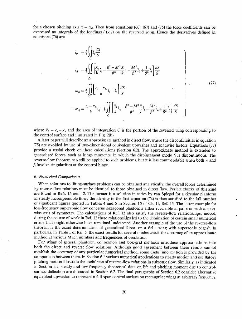
for a chosen pitching axis x -- Xo. Then from equations (66), (67) and (75) the force coefficients can be expressed as integrals of the loadings 7 (x,y) on the reversed wing. Hence the derivatives defined in equations (76) are
1# =
mm~
dS
b
.f12 __ M 2 ~ _ M 2_ 1 _ 1 dS
IIrCr-XO_ . ll -g
- -mq f l 2 - M 2 x ~ M2.7 1 ]7
(77)
where ~h = Cr--Xh and the area of integration C is the port ion of the reversed wing corresponding to the control surface and illustrated in Fig. 2(b).
• A later paper will describe an approximate method in direct flow, where the discontinuities in equation (75) are avoided by use of two-dimensional equivalent upwashes and spanwise factors. Equations (77) provide a useful check on these calculations (Section 6.2). The approximate method is extended to generalized forces, such as hinge moments, in which the displacement mode f~ is discontinuous. The reverse-flow theorem can still be applied to such problems, but it is less commendable when both w and f~ involve singularities at the control hinge.
6. Numerical Comparisons.
When solutions to lifting-surface problems can be obtained analytically, the overall forces determined by reverse-flow relations must be identical to those obtained in direct flow. Perfect checks of this kind are found in Refs. 15 and 12. The former is a solution in series by van Spiegel for a circular planform in steady incompressible flow; the identity in the first equation (74) is then satisfied to the full number of significant figures quoted in Tables 4 and 5 in Section 15 of Ch. II, Ref. 15. The latter example for low-frequency supersonic flow concerns hexagonal planforms either reversible in pairs or with a span- wise axis of symmetry. The calculations of Ref. 12 also satisfy the reverse-flow relationships; indeed, during the course of work in Ref. 12 these relationships led to the elimination of certain small numerical errors that might otherwise have remained undetected. Another example of the use of the reverse-flow theorem is the exact determination of generalized forces on a delta wing with supersonic edges 5. In particular, in Table 1 of Ref. 5, the exact results for several modes check the accuracy of an approximate method at various Mach numbers and frequencies of oscillation.
For wings of general planform, collocation and box-grid methods introduce approximations into both the direct and reverse flow solutions. Although good agreement between these results cannot establish the accuracy of any particular numerical method, some useful information is provided by the comparison between them. In Section 6.1 various numerical applications to steady motion and oscillatory pitching motion illustrate the usefulness of reverse-flow relations in subsonic flow. Similarly, as indicated in Section 5.2, steady and low-frequency theoretical data on lift and pitching moment due to control- surface deflection are discussed in Section 6.2. The final paragraphs of Section 6.2 consider alternative equivalent upwashes to represent a full-span control surface on rectangular wings at arbitrary frequency.
20

6.1. Results for Pitching 14~ngs. Overall force coefficients obtained by both direct-flow and reverse-flow solutions are presented in
Tables 1 to 3 and Figs. 3 to 10 for wings of moderate to low aspect ratio with planform varying from rectangular to highly swept arrowhead. The aerodynamic derivative coefficients for pitching oscillations are defined by equations (36) with k = ~ and v = o~/U = ~. With the exception of Figs. 5 and 10, the results to be discussed in this section are from collocation methods developed from. Multhopp's la subsonic lifting-surface theory; the refinement of Ref. 16 is incorporated for steady flow, for slow pitching oscillations (v~0) 14 and for the general oscillatory methods of Refs. 7 and 8.
Programmes for high-speed computers have extended the scope oI these collocation methods to solutions with more spanwise and chordwise positions, of number m and N respectively. Steady solutions are first considered. In direct flow the lift slope coefficient ~CrJOe = (CL}I and the aerodynamic centre
xac = ~(- Cm)I/(CL)j (78)
are defined by equation (61) with k = a. For wing planforms with a spanwise axis of symmetry, the reverse-flow relations of equations (73) and (74) lead to the same OCL/&Z = (CL)I but an alternative
xoc = c r - ~ ( C L ) 2 / ( C L h . (79)
Equations (78) and (79) are used to study the relative merits of particular combinations re(N) for certain planforms. Results for various solutions re(N)are presented in Table 1 for rectangular wings in subsonic flow over the range of reduced aspect ratio 0.2821 ~<flA~<4. The values of fl OCL/Oe for flA = 1 are in good agreement, but as flA increases to 2 and 4 there are notable differences between the various solutions re(N); for m = 7, an increase in N from 2 to 3 or 4 does not appear to improve accuracy when flA/> 2. In Figs. 3a and 3b, results for x J c show the effect of'varying independently the number of m spanwise and N chordwise collocation positions and illustrate the discrepancies between the direct-flow a n d reverse-flow solutions. Of the direct-flow results, it is noted that re(N) = 7(2) and 15(3) are in closest agreement for all flA. Results for m = 7 in Fig. 3a agree satisfactorily when ]~A = 1 but the discrepancy increases as flA or N increases; at/?A = 4 the discrepancy appears unacceptable for all N. In Fig. 3b for N = 3, an increase in m from 7 t o 15 is seen to decrease the discrepancy for all flA. Further com- parisons can be made from the two sets of values of x, Jc for rectangular wings in Table 1. It seems perhaps that N is best restricted* to the integer (~<4) nearest to (m+l)/2flA. As flA decreases from 1.6 0.2821 satisfactory agreement is maintained by the solution re(N)= 11(3). Similar comparisons for symmetrically tapered wings in steady subsonic flow are given in Table 2, with re(N) -- 11(3). Again there are significant discrepancies between the x,J~ values from equations (78) and (79) for the larger values of flA. Satisfactory agreement is evident for 1.<flA<2 but, in the absence of solutions for other combinations re(N), this alone does not establish the accuracy of the results.
Exact solutions are not generally available, but for the circular wing in incompressible flow van Spiegel's is solution establishes the absolute accuracy of collocation solutions. For a very low frequency, Woodcock w has tabulated solutions for various re(N) by the method of Ref. 7. The corresponding direct-flow and reverse-flow values of x,~/cr are obtained from equations (78) and (79) respectively. In Fig. 4 the discrepancy between these two values is plotted against the deficit in the direct-flow value from the exact value x,Jc, = 0.2395. Points for constant m are joined by dotted curves ; the more reliable dashed curves for constant N = 2, 4, 6 show in each case how,the solutions improve with increasing m. In only two cases, re(N) = 4(4) and re(N) = 4(2), do the discrepancies in aerodynamic centre exceed 0-007 c~, and errors of this order occur in both of the direct-flow and reverse-flow values. Whereas in the case re(N) -- 4(4) this is revealed by the application of equation (79), the case re(N) = 4(2) illustrates the possibility of a good reverse-flow check with inaccurate solutions. It is instructive to group the solutions according as N is greater or less than (m+ 1)/2A. From the discussion on rectangular wings, the latter group is expected to be more reliable and this is indicated by the solid circles in Fig. 4. Likewise, the solution re(N) = 7(2) from Ref. 14 is very satisfactory.
*This restriction is overcome by Garner and Fox by improved spanwise integration and a modified collocation method (A.R.C. 27926, April, 1966). ~
' 21

For a rectangular wing A = 4 describing pitching oscillations in incompressible flow, values of the lift derivatives lo and lo, obtained by two different collocation theories (Refs. 18 and 19), are plotted against frequency parameter ~ = co6/U in Fig. 5. The solutions denoted as reverse-flow were determined from the relations (41) with appropriate values of the plunging derivatives. The agreement between the direct-flow and reverse-flow solutions from the low-aspect-ratio theory of Lawrence and Gerber is is excellent throughout the range 0.25 ~ ~ ~2.0, but there are discrepancies between the results from the vortex-lattice theory of Ref. 19 for ~ > 1 ; probably two chordwise collocation positions are insufficient. It is interesting to see how well the results agree for ~< 0.6, especially as Refs. 18 and 19 introduce very distinct approximations into the, basic theory.
Pitching derivatives for highly sweptback wings oscillating at small frequency (9--*0) are plotted against pitching axis in Figs. 6 to 8. These results were evaluated by the method of Ref. 14 as indicated in Section 5.1; with re(N) = 15(3), the derivatives were determined by substituting direct-flow solutions into. equations (62) and from equations (71) by using solutions for the reversed wing. Comparisons in Fig. 6 for the cropped delta wing A = 1"8 at M = 0, show very good agreement between these solutions particularly for the d e r i v a t i v e - m o at all axis positions x o. In Fig. 7, the agreement is nearly as good for the cropped delta A = 3 at M = 0.8. Although this does not establish the accuracy of the solutions, it gives confidence in the use of the method for general planforms in subsonic flow. This is further sup- ported by the satisfactory results in Fig. 8 for a cropped arrowhead wing at M = 0.781. For the examples considered in Figs, 6'to 8 the reverse-flow relation for the derivative lo, namely (CL)I = (CL)I by equations (62) and (71), is satisfied to an accuracy of ½ per cent or better.
Solutions for high subsonic Mach number obtained by the general oscillatory theory of Ref.. 8 are presented in Table 3 and Fig. 9. For the planforms in Table 3 with a spanwise axis of symmetry, the reverse-flow relations in equations (41) lead to alternative results for lo and lo. The solutions for the rectangular wing A = 4 at M = 0.866 were obtained as the initial application of Ref. 8 with the limited number of collocation positions re(N) = 7(2): the discrepancy between the two ratios lo/lo at ~ = 0.3 is not dissimilar to that between the values of xac/c for/?A = 2 in Table 1. However, the discrepancies increase with the frequency parameter P, and from the numerical discrepancy of 0.04 in lo at ~ = 1-2 it is apparent that re(N) = 7(2) is inadequate when ~ is so large. Similarly, the rectangular wing A. = 2 at M = 0-866 and M = 0"99 is comparable with/~A = 1 and 0.2821 respectively and discrepancies from Table 3 follow the trend of those in Table i for the same value of m. There is good agreement at M = 0.99 when re(N) = 11(3) except for lo at ~ = 0"6. The results in Table 3 for the symmetrically tapered wing A = 4.329 at ~7 = 0.19 also show significant differences in l o, which can be attributed either to the small number of spanwise terms m or to the high subsonic Mach number M. In each case the reverse-flow check appears to indicate the order of accuracy in l o. In Fig. 9, the four pitching derivatives for the cropped arrowhead planform A = 2 at M = 0.781 are plotted against frequency parameter for 0 < ~ < 1 . These results correspond to re(N) = 15(3), the reverse-flow solutions being determined by equations (39) and (40). Discrepancies between the direct-flow and reverse-flow results are similar to those for ~--*0 and do not increase appreciably as ~ increases to 1.0.
A final comparison of the derivative l o for the symmetrically tapered wing A = 4.329 at ~ = 0.19 is made in Fig. 10 for the transonic range 0.9 < M < 1.2. Here results by different subsonic 8,2°, sonic 1° and supersonic 2~ lifting-surface methods show greater discrepancies for the Mach numbers closer to M = 1. Of interest for subsonic flow is the large difference between the results of Refs. 8 and 20 at M = 0.99, though the latter happens to satisfy the reverse-flow check. For supersonic flow both results by Ref. 21 show the kink at M = 1.035 when the leading edge becomes sonic.
6.2. Results for Control Surfaces.
Indirect force coefficients in subsonic flow due to steady or slowly oscillating control surfaces are presented in Figs. 11 to 16 for various symmetrical configurations of wing and control surface. The direct-flow solutions are evaluated by using the Multhopp low-frequency collocation method 14 with two-dimensional equivalent upwashes and spanwise factors in the case of part-span controls, as mentioned in Sect. 5.2. ,Thereverse-flow solutions for v ~ 0 are determined by using equations (77) with the appro-
22

priate reversed-wing solutions. The lift derivatives I, and l o and the pitching-moment derivatives m, and m~ are defined by equations (76) with length k = ~, frequency parameter ~ = o)~/U and pitching axis Xo = 0.
Firstly we consider steady motion. Let (CL)o~ denote the two-dimensional lift coefficient corresponding to infinite aspect ratio. Then Fig. 11 shows the lift factor CL/(CL)~o plotted against E, the ratio of the control chord to wing chord for a rectangular wing (/?A = 2) with a full-span deflected control surface. For control-surface calculations it would seem likely that greater numbers of collocation positions re(N) are needed in the numerical solutions. When the number of chordwise positions N is varied in solutions with m = 15, the reverse-flow solutions (N = 2,3,4) agree quite well for E> 0-3, but those for N = 2 become less satisfactory as E decreases. Both direct-flow and reverse-flow solutions involve greater uncertainties for the smaller values of E. Discrepancies between them indicate that N = 4 is least consistent for the whole range 0.05 ~<E~<0.50. Thus, it would seem that N = 3 provides the most systematic results when m = 15 and is the optimum choice for the rectangular wing of reduced aspect ratio/~A = 2. For re(N) = 15(3), Fig. 12 shows the steady centre of lift xcp/c defined similarly to equations (78) and (79). Only small discrepancies are found for/~A = 2 over the whole range of E; variation of reduced aspect ratio shows a striking improvement for/3A = 1 but much larger discrepancies for/~A = 4, as might be expected from the trends in Fig. 3b.
Low-frequency lift and pitching-moment derivatives are illustrated in Figs. 13 to 16 by Solutions re(N) = 15(3) for sweptback wings with oscillating part-span control-surfaces. In Figs. 13 and 14, damping derivatives l~ and -m~ for a cropped delta planform A = 1"8 at M = 0 are plotted against y,/s, where y, < y < s denotes the control span. For the unswept hinge line in Fig. 13, reverse-flow solutions are plotted for the range 0 <~y,]s<~0"9. Comparison of the direct flow results for y, = 0 indicates that the equivalent upwash procedure is satisfactory for the full-span control. A similar comparison in Fig. 14 for the 15 per cent chord controls shows slightly better agreement between the direct-flow and reverse-flow solutions. Although the discrepancies for y, = 0.5s in both figures are nearly double those for y, = 0, it is thought that the direct-flow treatment for slowly oscillating part-span controls gives reasonably good results for both types of control surface. A more severe test is the application to a cropped arrowhead wing with oscillating part-span controls in compressible flow M = 0.781 (Fig. 15). In this example the stiffness derivatives l, and -ran and the damping derivatives l o and -m~, in Figs. 15 and 16 respectively, show good agreement over the range 0 ~. y,/s <~0.9. Minor discrepancies between the solutions for the damping derivatives are apparent, especially the irregularities for small q, that may be attributable to the central kink of the trailing edge.
Section 4.3 describes reverse-flow methods of constructing equivalent upwashes to represent any configuration of wing with oscillating control surface. In the simplest application to a rectangular wing with full-span control of constant E, the equivalent upwash is independent of aspect ratio and identical for all spanwise collocation positions. However, the assumed form of load distribution does influence the equivalent upwash w~r(x). That based on Davies' method in equation (56) is linear in frequency and independent of Mach number; on the other hand Acum's theory 8 uses a wing loading proportional to e ~'~x/v and when this exponential is inserted into the integrands of the simultaneous equations (48) the present equivalent upwash from equation (43) remains independent of Mach number but is non-linear in frequency.
It is interesting to compare the present equivalent upwash in the special case v--*0 with that derived by Davies in equation (56). For a rectangular wing with full-span control of constant E, the present equivalent upwash will be of similar form
F~ = w~r/U
N - 1
= 2 ( ~ ) - ~'en (X/C) Ejn 0 n=O
(8o)
23

where the polynomials W.(¢) are defined by equatio n (50). The coefficients E.~.0 are determined by neglecting terms of O(v 2) in the set of simultaneous equations appropriate to Acum's loading as indicated above. For an arbitrary number of chordwise terms N, it can be shown that
Es.o = E's.o for n = 0,1 . . . . . ( N - 2 )
E' iv ~sinNOh sin(N+ 1)Oh_ 1 e,°o= - j f o r n = ( N - 1 )
(81)
where v = ooc/U and cos Oh = 1 - 2 E defines the control hinge. It follows from equations (56), (80) and (81) that the present equivalent upwash for v ~ 0 amounts to Davies' equivalent upwash with the imaginary increment
cos(N-½)O[sinNOh sin(N + 1)Oh_l AF~(x/c) = - i v 4z~cos½0 L - - ~ q N+- i -.J' (82)
where x = lc(1 + cos 0). This increment vanishes if
i.e.,
cos(N-½)O = O,
x/c = ½ ~ l - c o s ~ ) , { p = 1,2.. . ( N - l ) } ,
which may be recognised as the collocation positions appropriate to ( N - 1) chordwise terms. When N = 3, both the real and imaginary parts of F~ are quadratic in x/c. Curves of R(F~) and I(F~s/v)
are presented in Figs. 17 and 18 for E = 0.25; while Davies gives curves independent of frequency, those based on Acum's wing loading 8 depend on frequency. The latter calculations are plotted for v--+0 and v = 2.0, and it is interesting to find the frequency effect is so small. When v-*0, the two methods give identical R(F~r) but fundamentally different curves of I(F~r/v), as is apparent from equation (82); the differences can read!ly be calculated for any values of N and E. Applications of the present equivalent upwash and Davies equivalent u p , ash with N = 3 are made to different full-span controls oscillating with frequen-ey parameter 7̀ = oUU\= 0"6 on a rectangular wing A = 2 at M = 0.866. Lift and pitching moment about the leading edge are g\ven as derivatives in Table 4 for control-chord ratios in the range 0.05~E-~0-40. Results obtained by m~,ans of the reverse-flow theorem (Section 4.1) are also tabulated. All solutions were calculated from Acum's 8 lifting-surface theory with re(N) = 7(3). The three sets of results are compared in Figs. 19 and 20, where stiffness and damping derivatives respectively are plotted against E. The two sets based on equivalent uowashes show good agreement in l~ for all values of E; the differences between values of the other derivatives appear systematic and are much smaller than Fig. 18 might suggest. The excellent agreement in the tabulated values for E = 0.20 is easily explained; when N = 3, equation (82) gives zero increment AF~ for E = 0-1962, and the small effect of a change in frequency from ,7--*0 to ~ = 0.6 on the present equivalent upwash (Figs. 17 and 18) hardly influences the alfferences between the two sets'. The third set by reverse flow shows good agreement with the other two as regards stiffness derivatives, but poorer agreement on l 0 and rno in Fig. 20. These last results are not necessarily the least, accurate, since the chief cause of inaccuracy is probably the small value m = 7 and errors from this cause would not be revealed by comparisons between the results from the two sets of equivalent upwashes.
Although me lift and moment derivatives appear relatively insensitive to the changes in equivalent upwash distribution in Fig. 18, this would be less true of more complicated generalized forces. It is tempting to apply these distributions to discontinuous displacement modes, to obtain rough estimates of, say, control hinge moment or hinge reaction. This procedure would naturally require a larger value
24

of N, but in any case the present equivalent upwash would probably be the better choice when Acum's theory is used. On theother hand, for all but the most special wing-control configurations, Davies' equivalent upwash from equations (49) and (54) is much less difficult to calculate.
7. Concluding Remarks. Even in the restricted field of oscillatory aerodynamics the reverse-flow theorem of equation (6) is
seen to have numerous roles. At the two extremes, both sides of the equation may be evaluated either analytically or by some approximate technique, and the resulting agreement or discrepancy is often found to provide useful information. Other applications are illustrated in equations (39) and (40), (71) and (73), or (49) and (54); these involve analytical manipulation of equation (6) before the numerical comparisons are introduced, and may lead to more economical computations or again provide indications of accuracy or error.
In relation to analytical solutions, the reverse-flow theorem may give an alternative expression for a generalized oscillatory force involving simpler algebra. In supersonic flow, for example, it may be pre- ferable to treat a subsonic leading edge rather than a subsonic trailing edge. Where solutions can be obtained in both direct and reverse flow as expansions in powers of frequency or other parameters, an exact analytical check becomes available.
In general, the solutions for oscillating lifting surfaces involve the use of collocation or a box grid, and it is impracticable tO establish the absolute accuracy of such numerical approximations. Independent solutions to the same problem can reveal the presence of errors, but not necessarily their full amount; a nearly perfect check by application of the reverse-flow theorem might well be illusory. There is no basis for preferring results by reverse flow to those by direct flow. The examples in Tables 1 to 4 and Figs. 3 to 20 provide ample evidence of discrepancies simply revealed (Fig. 3) and comparisons which encourage confidence (Fig. 6). The latter place current theoretical methods in a favourable light.
In Section 4.2, there are derived relationships (39) and (40) between the plunging and pitching derivatives for any planform and for the corresponding reversed planform. These are convenient, but reduced in number, when the planform has streamwise symmetry (Table 3). For a more general planform in high subsonic flow satisfactory checks on the derivatives are found for a range of frequency parameter (Fig. 9).
When the frequency parameter is very small, many of the relationships of Section 4.2 become trivial or useless. However, the analysis in Section 5.1 leads to seven equations (73) relating aerodynamic coefficients for the direct and reversed planforms, that determine the required subsonic pitching derivatives in equations (62) and (71) respectively. Comparative calculations from the two sets of coefficients are very satisfactory (Fig. 8). A corresponding reverse-flow treatment of slowly oscillating control surfaces is outlined in Section 5.2; the calculated lift and pitching moment compare reasonably with approximate solutions in direct flow from equivalent two-dimensional upwashes with allowance for part-span controls (Figs. 15 and 16).
The subject of smooth equivalent upwash distributions to represent oscillating control surfaces is analysed in Section 4.3. An appraisal is made of the important method developed by Davies 7 on the basis of the reverse-flow theorem. When collocation is carried out by the lifting-surface theory of Ref. 8, alternative equivalent upwash distributions are more appropriate. In general, those of Davies in equations (49) and (54) are linear in frequency and much less difficult to calculate. In a simple application to the lift and pitching moment on a rectangular wing with rapidly oscillating full-span controls, the two procedures are in remarkable agreement (Figs. 19 and 20).
8. Acknowledgements. The authors acknowledge the assistance of Mrs. S. Lucas who, with the co-operation of Mathematics
Divisio n, N.P.L., was responsible for most of the calculations and helped to prepare the illustrations.
i5
a
A
Aiq, Bjp
bj
c(y)
c~(y)
Or
C
CL
C..
(cL)., ( - c,.).
c~, - c *
OC ff &z
E
E sm., Ej,..
f~(x,y)
F j(x,y)
f~,(x,y)
AF~(x/c)
i
J
k
l(x,y,t)
tJ~,y)
I~(x,y)
l.(x,y)
71, 7n
LIST OF SYMBOLS
Speed of sound
Aspect ratio of planform (= 4s2/S)
Coefficients relating Qu and Qpq in equation (18)
Amplitude of oscillation of wing in fh mode
Amplitude of oscillation of reversed wing in qth mode
Local wing chord; chord of rectangular wing
Geometric mean chord (S/2s)
Local chord of control surface
Root chord of wing
Area of control surface
Lift coefficient (= L/½pU2S)
Pitching moment coefficient (= ~ /½p2 Sk )
Coefficients CL, --Cm(xo = 0) corresponding to steady incidence a.
Force coefficients defined in equation (61)
Lift curve slope [ = (CLh]
Ratio of control chord to wing chord
Coefficients determining equivalent upwash in equations (43), (49) respectively
Non-dimensional displacement for wing in i th mode
Non-dimensional displacement for reversed wing in pth mode
Non-dimensional displacement in jth mode for wing in reverse flow [equation (12)3
Non-dimensional equivalent upwash function in equation (43) or (49)
Increment in equation (82)
Suffix denoting displacement mode in direct flow and upwash mode in reverse flow
Suffix denoting upwash mode in direct flow and displacement mode in reverse. flow
Suffix denoting discontinuous mode j.
Representative length, ~ in numerical examples
Non-dimensional load distribution in equation (3)
J Complex load distribution corresponding to upwash wj
Complex load distribution in equation (45) corresponding to w3
Load distribution due to steady incidence a.
Complex load distribution on reversed wing corresponding to upwash~q
Complex load distributions on reversed wing in equation (66)
26

/z, l~
lolo
L
Li(x,Y)
m
mz, m ~
mo~ m#
m,. m#
M
M
d/l
N
Ap(x.y.t)
AP(x.y.O
Q~j
s
S
t
U
w(x,y,t)
w~(x,y)
w~(x,y) %(~,Y)
WI, WII
W(x,y,t)
W~(x,y)
(x,y,z)
Xo
Xa¢
Xcp
Xh(Y)
LIST OF SYMBOLS--continued
Lift derivatives for plunging oscillations in equation (36)
Lift derivatives for pitching oscillations in equation (36)
Lift derivatives for control oscillations in equation .(76)
' Lift force
Complex load distribution on wing in reverse flow corresponding to upwash W~
Rolling moment about x-axis in equation (21)
Number of spanwise terms (positions) in collocation solutions
Pitching-moment derivatives for plunging oscillations in equation (36)
Pitching-moment derivatives for pitching oscillations in equation (36)
Pitching-moment derivatives for control oscillations in equation (76)
Mach number of free stream (= U/a)
Number of spanwise terms in Section 4.3
Nose-up pitching moment about axis x = Xo, z = 0
Number of chordwise terms (positions) in collocation solutions
Local pressure difference, lift per unit area
Local pressure difference across wing in reverse flow
Generalized aerodynamic force coefficient in equation (5)
Generalized aerodynamic force coefficient for reversed wing in equation (13)
Semi-span of wing
Area of wing planform
Time
Free-stream velocity
Upwash distribution on wing
Complex upwash for wing i n f h mode [-equation (2)]
Equivalent upwash [ = UF~r(x,y)]
Complex upwash for reversed wing in qth mode
Upwash distributions on reversed wing in equation (64)
Upwash distribution on wing in reverse flow
Complex upwash in reverse flow for wing in i th mode
Rectangular co-ordinates in Fig. la
Location of pitching axis
Location of aerodynamic centre in equation (78) or (79)
Centre of lift for steady control deflection
Hinge line of control surface
• 2 7

xz(y)
xt(y)
(~,y,~)
Y~
z(x,y,t)
Z o
zj(x,y)
Z(x,y,t)
C~
~.(x,y) ~.(~,y)
qo
0
Oh
Oo
V
(~,n)
P
4)
(D
Superscript
LIST OF SYMBOLS--continued
Leading edge of wing
Trailing edge of wing
Rectangular co-ordinates for reversed wing in Fig. lc
Ordinate defining span of outboard control surface in Fig. 2a
Upward deflection of wing surface
Amplitude of plunging oscillation
Upward deflection of wing in fh mode
Upward deflection of wing surface in reverse flow
Incidence, downwash angle (= -w/U)
Steady incidence distributions in equation (59)
Steady incidence distributions in equation (65)
Compressibility factor (1 - M2) ~
Amplitude of control-surface oscillation
Angular chordwise ordinate for reversed wing in equation (50)
Ordinate of control hinge [-= cos- 1 (1-2E)]
Amplitude of pitching oscillation
Frequency parameter (= o~k/U)
Mean frequency parameter (= (nUU)
Non-dimensional co-ordinates defined in equation (47)
Free-stream density
Angular spanwise ordinate (= cos-lq)
Polynomial in equation (50) of degree r
Circular frequency of oscillation
Polynomial in equation (52) of degree s
Bar indicates that symbol is referred to co-ordinate system (2,y,~) of reversed wing, e.g., xz, x~ as in Fig. 2b; i o, 70 denote lift derivatives for reversed wing with pitching axis ~ = ~o-
28 ?.,

REFERENCES
No. Author(s)
1 A.H. Flax . . . .
2 A.H. Flax . . . . . .
3 M.A. Heaslet and .. J. R. Spreiter
4 G. Zartarian, P. T. Hsu and H. M. Voss
5 J. Walsh, G. Zartarian and H. M. Voss
6 V.J.E. Stark . . . .
7 D.E. Davies
8 W.E.A. Acum . . . .
9 D.E. Williams . . . .
10 D.E. Davies . . . .
11 C.E. Watkins . . . .
12 D.E. Lehrian . . . .
77tie, etc.
General reverse-flow and variational theorems in lifting-surface theory.
J.Aero Sci., Vol. 19, p. 361-374, 1952.
Reverse-flow and variational theorems non-stationary compressible flow.
J.Aero. Sci., Vol. 20, p. 120-126, 1953.
Reciprocity relations in aerodynamics. N.A.C.A. Report 1119, 1953.
for lifting surfaces in
Application of numerical integration techniques to the low aspect-ratio flutter problem in subsonic and supersonic flows.
Aeroelastic and Structures Research Laboratory, Mass. Inst. of Tech. Tech. Report 52-3, October, 1954.
Generalized aerodynamic forces on the delta wing with super- sonic leading edges.
J.Aero. Sci., Vol. 21, p. 739-748, 1954.
Aerodynamic forces on rectangular wings oscillating in subsonic flow.
SAAB TN 44, February, 1960.
Calculation of unsteady generalised airforces on a thin wing oscillating harmonically in subsonic flow.
A.R.C.R. & M. 3409. August, 1963.
Theory of lifting surfaces oscillating at general frequencies in a stream of high subsonic Mach number.
A.R.C.17 824. August, 1955. Corri: 25th October, 1956. [See also A.R.C.18 630 (1956), 19 229 (1957) and 20 771 (1959)].
Three-dimensional subsonic theory. Manual on Aeroelasticity, Vol. 2, Ch. 3. AGARD (ed., W. P. Jones).
Three-dimensional sonic theory. Manual on Aeroelasticity, Vol. 2, Ch. 4. AGARD (ed., W. P. Jones).
Three-dimensional supersonic theory. Manual on Aeroelasticity, Vol. 2, Ch. 5. AGARD (ed., W. P. Jones).
Calculation of stability derivatives for tapered wings of hexagonal planform oscillating in a supersonic stream.
A.R.C.R. & M. 3298. September, 1960.
29

No. Author(s)
13 H. Multhopp ..
14 H.C. Garner ..
15 E. van Spiegel . . . .
16 K.W. Mangler an&. .. B. F. R. Spencer
17 D.L. Woodcock . . . .
18 H.R. Lawrence and E. H. Gerber
19 D.E. Lehrian . . . .
20 J.R. Richardson . . . .
21 D.J. Allen and D. S. Sadler
REFERENCES--continued
Title, etc.
Methods for calculating the lift distribution of wings. (Subsonic lifting-surface theory).
A.R.C.R. & M. 2884. January, 1950.
Multhopp's subsonic lifting-surface theory of wings in slow pitching oscillations.
A.R.C.R. & M. 2885. July, 1952.
Boundary Value problems in lifting-surface theory. N.L.L Technical Report W.1. March, 1959.
Some remarks on Multhopp's subsonic lifting-surface theory. A.R.C.R. & M. 2926. August, 1952.
On the accuracy of collocation solutions of the integral equation of linearized subsonic flow past an oscillating aerofoil.
Proceedings of the International Symposium on Analogue and Digital Techniques Applied to Aeronautics, Li6ge, 9th to 12th September, 1963.
The aerodynamic forces on low aspect-ratio wings oscillating in an incompressible flow.
J.Aero. Sci., Vol. 19, p. 769-781, November, 1952.
Calculated derivatives for rectangular wings oscillating in com- pressible subsonic flow.
A.R.C.R. & M. 3068. July, 1956.
A method for calculating the lifting forces on wings (Unsteady subsonic and supersonic lifting-surface theory ) .
A.R.C.R. & M. 3157. April, 1955.
Oscillatory aerodynamic forces in linearised supersonic flow for arbitrary frequencies, planforms and Mach numbers.
A.R.C.R. & M. 3415. January, 1963.
30

TABLE 1
Calculated Aerodynamic Centres of Rectangular 14~n#s in Direct Subsonic Flow and by Reverse-Flow Theorem
~A re(N)* 0__c
4 7(2) 3-5792 7(3) 3.4809 7(4) 3.4194
15(2) 3.6251 15(3) 3"6013 15(4) 3.5802
3 15(2) 3-1522
2 7(2) 2.4785 7(3) 2.4711 7(4) 2.4540
15(2) 2.4750 15(3) 2.4782 15(4) 2-4738
1 7(2) 1.4580 7(3) 1.4617 7(4) 1.4601
11(3) 1-4610
15(3) 1.4609
1.6 11(3) 2.1226
1.2 11(3) 1-7007
1.0 11(3) 1-4610
0.7599 11(3) 1.1z~63
0.6245 11(3) 0.9560
0-4862 11(3) 0.7533
0-2821 11(3) 0.4422
x.c/c Direct Reverse
0.2290 0-2519 0.2396 0-2669 0.2499 0-2661
0.2297 0.2334 0.2284 0.2428 0-2327 0.2454
0-2239 0.2238
0.2076 0.2112 0.2064 0.2209 0-2113 0.2245
0.2101 0.2084 0.2077 0.2105 0.2069 0.2126
0.1697 0-1670 0.1652 0.1680 0.1644 0-1701
0.1667 0"1663
0-1671 0.1666
0-1962 0.1988
0.1793 0.1797
0.1667 0"1663
0.1456 0.1447
0.1298 0-1289
0-1102 0.1092
0"0755 0.0740
* m and N denote the respective numbers of collocation points in the spanwise and chordwise directions.
31

TABLE 2
Calculated Aerodynamic Centres of Symmetrically Tapered 14~ngs* in Direct Subsonic Flow and by Reverse-Flow Theorem
4-329
3.463
2.598
1.887
1.352
0.611
m(N) fi aCE aa
11(3)
11(3)
11(3)
11(3)
11(3)
11(3)
3.8205
3.4674
2.9684
2-4088
1-8718
0.9326
Xae/ C Direct Reverse
0'5001 0.5196
0.4943 0-5087
0.4875 0-4948
0.4793 0.4793
0.4690 0.4634
0.4389 0.4320
TABLE 3
Lift Derivatives Calculated by Ref 8 for Three Pitchin 0 Wings (Xo = O) in Direct Subsonic Flow and by Reverse-Flow Theorem
lMng
Rect. A = 4
Rect. A = 2
A = 4"329*
M
0.866
0.866
0.990
0-900
0.990
m(N)
7(2) 7(2) 7(2)
11(3) 7(3) 7(3)
0-3 0.6 1-2
0"3 0.3 0-6
0-1 0-3 0.6
Direct
2.432 2.413 2.184
1.486 1-486 1.625
Reverse
2-428 2 .399 2-165
1.486 1.487 1.621
11(3) 11(3) 11(3)
0"19 0"19
1.592 1.856 1.982
1.591 1-854 1-978
Direct
0"892 0"960 0"936
1-691 1"692 1-698
2"310 1"784 1.022
11(3) 7(3)
11(3) 7(3)
0'19 0"19
2"737 2"742
3-000 2.967
2.736 2.741
2.999 2.961
1"278 1-281
-2"217 - 2"460
lo
Reverse
0.905 0.979 0.978
1.690 1.695 1.700
2"310 1.785 1"035
1"281 1"305
- 2-058 -2 .291
* The symmetrically tapered planform A = 4.329 is illustrated in Fig. 10. Root chord c~ = 1.58&
32

TABLE 4
Derivatives for Oscillating Full-Span Control Surfaces on a Rectangular Wing (A = 2, M = 0.866, "~ = 0-6, X° = 0)
Derivative
-:- mq
Method*
1
2 3
E = 0.05
0.478 0-476 0.487
-0 .390 -0 .380 - 0.373
0"460 0.447 0.466
- 0'205 - 0.201 -0 .183
E = 0-10
0.679 0.677 0.689
-0 .462 -0 .455 -0 .442
0.610 0.600 0.617
- 0-200 -0 .196 -0 .173
E = 0.20
0.960 0.960 0.969
-0-420 - 0.420 -0 .399
0.754 0-754 0-760
-0 .058 - 0.059 -0-035
E = 0-30
1.167 1.168 1-172
-0 .252 -0 .259 -0 .234
0.799 0.807 0.802
0.152 0"148 0"169
E = 0.40
1.326 1.328 1:327
-0 .016 - 0"024 - 0.002
0.787 0"798 0-787
0-380 0.375 0.389
* Acum's theory of Ref. 8 with re(N) = 7(3) is applied with three different conditions: 1. Present equivalent upwash (Section 6.2) 2. Davies' equivalent upwash from equation (56) 3. Reverse-flow solution (Section 4.1).
33 cJ
(a) Direct flow
~- U
(b) Reverse flow
(c) Reversed win~
L~
Y Oz upwards
Y
~ x U o
0
O~ upwards
FIG. 1, Co-ordinate systems.
(a) Direct f low
Control rotation
o.~ . . - ' ;Z71 - ~ ,o-~ ,-~'
- - . - u ".., \ = = - (x -~h~
(b) Reversed wing
-----~U O
Plunging -s.<y ~,s
7oi -z o ¢ i=t 8
! xt <,
FIo. 2. Control surface geometry. Lift due to control rotation.

0.2(
0,24
0.22 Xoc
c
0.20
0,I0
0"16
0"26
0"24
O'ZZ
¢
O.ZO
0"10
0"16
FIG. 3.
(0) E//ect of N (m ,-7)
. / -,," "
j J "
e,-
j f f f j , ~
j f l f
f
Direct-flow solution
. . . . Reverse-flow solution
z /3A 3
(b) Effect of
/ / "
,,,"..-.~ ,"/7/
. , '~ Y
m Number of spanwise terms
N N~mbcr of chordwise terms
~BA 3 4
7 [4)
7 (z~ 7 (4)
7 (z)
7(3)
ns(~) 7(3)
is(3)
Aerodynamic centres of rectangular wings in subsonic flow for various re(N).
0"012
w -~ 0"010
o
~ o.oo8 CI
I
0.006 tB 0
0.004
0.002
-0 .002 - 0.004
--: ::_-I.~oc A = 4 / r Cr
Exact value xclc/Cr= 0,2395 (van Spiegel, Ref, IS)
Constant m ~Woo~cock I Const onl N J ( v - 0,[~ff,17
T O N > ( m + l ) / 2 A • N < ( r n + l ) / 2 A
. ° • • . - - . . . . . . . . . . . . . . . , .
-"" "~ 4 ('4) m--4 .7 / ",
o,*" ,., / \ y , / !
°. ', ,, '" / :
, ' " Na6 N~4/
... ...... ..... .../ ..- ..... ,,(& ~,, i
~'"" /'\ i e(6) . / :, ,, o6 (z) : :
/ 0~ -.N-2 i ./ ~
/ 12 (4) 4 (z) f
~ . ~7 (z) / r~.14
20(4) I -0 .002 0 0"002 0"004 0"006
Exact value - Direct flaw value
FIG. 4. Aerodynamic centre of circular wing in incompressible flow; differences in Xac/Cr from
solut!ons for various re(N).
0.008

1,8
~ k f ~ 1.6 ~ ~ ~ ~ ~-----'-~,~ ~ t . . . ~ 0 ,
1.4 /
1.2
1 . 0
'kXX
Solution Re/. 18 Ref. 19 \ Direct-flow - - ~ \ Reverse-flow A ---o---- ~ \
k ' \
0.8
0.6
0.4
0 .2
0 0'5 : 1.0 ~ 1"5 2"0 Z.S
FIG. 5. Variation of lift derivatives lo and lo with frequency parameter for a pitching rectangular
wing (A = 4, M = 0, Xo = 0).
2,0
1".~, ~ ~
1,6
1"4
1,2
,oXx, 0,8 \ 0'4
0'2
0
-0-2
-0"4
-0 "G 0 0.Z
FZG. 6.
D;r¢ct-flow solution ~ mCN~ i ~ , . . . . . Reverse-fl~ solut~J=l$(3) I
%
\ \
\
\
\ 0"4 0.6 0"8Xo]~l'0 1.2 I-4 I-6 1"8
Oscillatory derivatives against pitching axis of a cropped delta wing
(A = 1.8, M = 0, ~ 0 ) .

2"0
I.B
1.6 ~
1"4 " ~
i .2
I ' 0
0"8
0"6
0"4
O"
-0 "2
-0"4
-0"6 0 0'2
FIo. 7.
\\
% \ \
~'° \
Direct-flow solution~ re(N} . . . . . R~vcr,aG flow solution J~15(3)
/ -2
0.4 0-6 O-Bxo] 1.0 I-2 1,4 . 1.6
Oscillatory derivatives against pitching axis of a cropped delta wing
(A = 3-0, M = 0.8, ~--*0).
hh
1"8
1"6 ~ Dir~at-flow em&L~a'~m(N')
..... Rmve'~q~ ~u~l~m(~O
l°t
O,6 ~ l
\ 0;4
0"2
\
-0.;
-0 .d 0.4 0.6 0.8
FIG. 8. Oscillatory derivatives against pitching axis of an arrowhead wing
(A = 2.0, M = 0.781, ~ 0 ) .
\ ~x
"m 0
\ 1.0 I "2 1"4 I "6 | -8 XolE

C~
1"4~
1.4( " ' ~ 1"20
/ 1.15 ~ - - - -
'0 /::0 7 1.3! /
/ / 1,30 ,~==... ~ / 1.05
1,2! P001 0 0'2 0.4 3 0.6 0.8 1.0 0 0.2 0 -4~0"6 0-8 I '0
Direct-flow solution ]. Refs.8,14 . . . . . Rewrseoflowsolution [ re(N)-15('5)
0.1 5 0-G0
0'10 ~ 0"55 I
.
0.05 " ~, ~ 0"50
0 0"451 0 0"2 0"4 ~ 0.6 0"6 1"0 0 0,2 0'4 -v 0"6 0-8 1.0
F]G. 9. Effect of frequency parameter on pitching derivatives of an arrowhead wing
(A = 2.0, M = 0.781, xo = g).
1"5
I - { '~
0•5
zo 0
-0 -5
- I ' 0
- I "5
- 2 -0
-Z ' 5
-3 -0
-3•5 0"9O
FIG. 10.
Direct Reverse Method f low f l o w
E3
Acum (Ref.8) • ~7 Richordson (Ref. Z0) ~ Cl
Oovis (Ref.10) O o
Allen and ScKIler (Ref.21) ~ t,
~'I l i
A=4-329 ; ~=0-19
o.
o°
• [
0"95 I'00 1"05 M I'10 1"15 1"20
Transonic variation of l o for a symmetric- ally tapered wing•
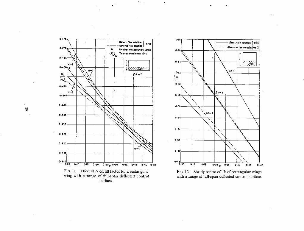
0.475 \
0,4TC ~\\
0.46! ~ \ \
N:4 \ \ \ 0.46C ~ \ \
N-3 e, ~ /
- - \ V (% 0.456 ~
N=2 ~ \
0.440
0.435
0.43
0,42
0.420
0.415
Direct-flowsolution ~ m-15 . . . . . Reverse-flow so~eaonj
N Number of chordwlse terms (CL) m Two-dimensional lift
/3A=2
- N
N =4
0-410 o.os oqo O.lS o-zo o-zs e 0-30 0.33 0-40 0-43 o-so
FIG. 11. Effect of N on lift factor for a rectangular wing with a range of full-span deflected control
surface.
0"6B
o \ 0,64
0.62 xc.__P e 0.60
\ \
0.58
0.5q
0.5
0.52
0"50
0"48
0"46 0-03
\ \
\
\
• \ ~ A =4
\
Direct-flow solution lm(N~ ----Reverse-flow SolutionJ-13(3)
d
BA- 2
, \
~ , \
'<,,, e,lO O.lS o.zo E o.ZS 0-30 0.3s 0 -40
FIG. 12. Steady centre of lift of rectangular wings with a range of full-span deflected control surface.

0.24
X o.zz \
\
O,ZO
0.18
0.1,.
0.14
O,IZ ~ "-~
O-IC
0"08
0 .06
0 .04
0-02
' \ \
\
\ \
D i r e c t - f l ~ 5olutfon~ m(N) . . . . . Reverse-flow solut(onJ=lS(3)
\ \ \ \
\ \
\ -m~
\ \
\ ~,.
%
'Ya '
c = s(7s-61Yl)l 18 Of= 5s / I 8
\ \
\ \
" - %
\ \
%
0 0.1 0"Z 0"3 0"4ya/s 0"5 0-6 0-7 0-8 0-9
FIG. 13. Damping derivatives l~ and -mo against control span of a cropped delta wing with constant-
chord controls (A = 1.8, M = 0, 9~0).
O.lO
o.o~
0'08
0"O7
0,06
0"05
0"04
O,OZ
0.01
0
-0.01
\ \ \ \ \
\ \
\
0 Direct.-flowsolution ~ m(N) Reverse-flow solut.ionJ - 15 (3)
\ \ \ \ \
\ \
\
\ \
\ \
\
c ~ s (Ts- 6[yl)/l~ cf=O'lSc
\ \
\ \
\ \
"N
0.1 O'Z 0"3 0,4 0,8 0"6 0-7 O, 8 0"9 ya/s
FIG. 14. Damping derivatives I~ and - m o against control span of a cropped delta wing with 15 per
cent chord control (A = 1.8, M = 0, ~ 0 ) .

1"3 \ ~
1.2
1.0
0.9 ~ 0"8 \'~
o, \ \ 0,6
0"5
0.4
0.3
0.2
0"1
Direct-flow solution l rn(N) . . . . Reverse-flow solutionJ ~15 (3)
\ \
\ \
, /
0 0 0.1 0.2 0.3
Cr =(Z4~+3) s/4 c - Cr- (4~- ½)IY ~- (3s - Z yl)/8
~ m~
\
0,4 yo/~ 0,5 0.6 0,7 0.8 0"9
FIG. 15. Oscillatory lift and moment against control span of arrowhead wing; stiffness deriva-
tives for M = 0.781 and ~--*0.
. . . . Rever1~-flow solutionJ - 15 B) O'OZ
0'01
-0'01 I ""
00, ~ ~ ~ / -°°: <~ 2~ j
-0'05 /
/ -0.0, / / ~
-0"0' / / / \ Z~
~0~0~
0 0
-0. I0~ 0"1 O,Z 0-3 0"4 ya/$0'5 0.6 0.7 0.1~ 0.9
FIG.16. Oscillatory lift and moment against control span of arrowhead wing; damping deriva-
tives for M = 0.781 and ~--*0.

_ _ ~ - - - o Eqn.(56) Davies" equivalent upwash
0,10
"o ----PO} Present equivalent, upwash (Section 6.2)
. . . . . . Eqn. ('56) Davies' equivalent upwash
t~
\ °
-13"
- 0 . 6
- 0 . 8
-I.O I
- I . 2 0 0.2 0.4 x/c 0.6 0'.8 I-0
FIG. 17. Real part of equivalent upwash distri- butions (N = 3) for rectangular wings with
oscillating full-span control (E = 0.25).
0.05
--0"0
// \ I II \\
I II ~ I I I
-0-10 /
-0-15
-0-20
-0- 25 0 0.2 0.4 x /c 0.6 0.8 1,0
FIG. 18. Imaginary part of equivalent upwash distributions (N- -3 ) for rectangular wings with
oscillating full-span control (E = 0"25).

a*
©
>
o~
1.4
1.3
0.0
0'7
S f ° '6j/ '~"
0. g
Present equivalent upwash
. . . . . Davies' equivalent upwash
- - - - - Reverse - f low solution
/ /
/ J
/ /
f -m (% = o)
m (~) = 7(3)
0.~ 0.05 0,10 0-15 0.20 E 0-25 0.30 0-35 0,4
FIG. 19. Stiffness derivatives I, and. - m , against chord of full-span control on a rec tangular wing
(A = 2, M = 0.866, 9 = 0.6).
0.4
0.3
Present. equivaient upwash
Davies ~ equivalent upwash
Reverse - flow solution
0'Z
0 /
0 / / / J<
-0.1 / / ~
-0-2
-0' 3 / /
-0.4 j ~ \
=7(3)
( x o = 0 )
/
FIG. 20. D a m p i n g derivatives l0 and - m o against chord of full-span control on a rec tangular wing
(A = 2, M = 0.866, ~ = 0"6).
-0.5 0.05 0.10 0.15 0-20 E 0.25 0-30 0.35 0"40

R. & M. No. 3488
© Crown copyright, 1967
Published by HER MAJESTY'S STATIONERY OFFICE
To be purchased from 49 High Holborn, London w.c.1 423 Oxford Street, London w.1 13A Castle Street, Edinburgh 2
109 St. Mary Street, Cardiff Brazennose Street/Manchester 2
50 Fairfax Street, Bristol 1 35 Smallbrook, Ringway, Birmingham 5
7-I 1 Linenhall ELreet, Belfast 2. or through any bookseller
Ro & Mo No. 348g
S.O. C o d e N o . 23-3488


