Embed Size (px)
Citation preview

UIC FREIGHT DEPARTMENTComparative analysis of the combined transport
usages and standards (CACTUS)Final Report
October 2021

ISBN 978-2-7461-3130-9
WarningNo part of this publication may be copied, reproduced or distributed by any means whatsoever, including electronic, except for private and individual use, without the express permission of the International Union of Railways (UIC). The same applies for translation, adaptation or transformation, arrangement or reproduction by any method or procedure whatsoever. The sole exceptions - noting the author’s name and the source - are “analyses and brief quotations justified by the critical, argumentative, educational, scientific or informative nature of the publication into which they are incorporated” (Articles L 122-4 and L122-5 of the French Intellectual Property Code).
© International Union of Railways (UIC) - Paris, 2021
1
ContentsForeword ........................................................................................................................................... 2Acronyms and abbreviations ............................................................................................................. 3Reference documents ....................................................................................................................... 41. Introduction .................................................................................................................................. 5
1.1. Background ........................................................................................................................... 51.2. The CACTUS Project ............................................................................................................ 5
2. Scope ........................................................................................................................................... 73. Codification in combined transport ............................................................................................... 8
3.1. Allocation of the wagon compatibility code ............................................................................ 93.2. Codification of ILUs ............................................................................................................. 123.3. Combined Transport Profiles and codification of combined transport lines ......................... 143.4. Identification of the entities in charge of coding CT lines, approving and coding ILUs, and
allocating the WCC and correction digits to CT wagons ........................................................ 153.4.1. Coding CT lines ......................................................................................................... 153.4.2. Approving and coding ILUs ....................................................................................... 153.4.3. Allocation of WCC and correction digits to CT wagons ............................................. 16
4. Wagon-related topics ................................................................................................................. 174.1. Overview of current regulations, standards and guidelines ................................................. 174.2. Overlaps, duplications and contradictions ........................................................................... 214.3. Potential areas of improvement, cross-referencing and harmonisation needs ................... 51
5. ILU-related topics ....................................................................................................................... 565.1. Intermodal Loading Units for vertical transhipment ............................................................. 56
5.1.1. Semi-trailers .............................................................................................................. 565.1.2. ISO containers .......................................................................................................... 895.1.3. ILUs other than ISO containers and semi-trailers ................................................... 116
5.2. ILUs for horizontal transhipment (other than semi-trailers) ............................................... 1635.2.1. Roller units .............................................................................................................. 163
6. Infrastructure-related topics ..................................................................................................... 1746.1. CT lines ............................................................................................................................. 175
6.1.1. Overview of current regulations, standards and guidelines .................................... 1756.1.2. Overlaps, duplications and contradictions ............................................................... 1766.1.3. Potential areas of improvement, cross-referencing and harmonisation needs ....... 183
7. Recommendations ................................................................................................................... 1877.1. The codification system ..................................................................................................... 1877.2. CT wagons ........................................................................................................................ 1897.3. Intermodal Loading Units .................................................................................................. 1917.4. CT lines ............................................................................................................................. 196
Appendix A: tables and figures ...................................................................................................... 197A.1. List of tables .................................................................................................................... 197A.2. List of figures ................................................................................................................... 197
Appendix B .................................................................................................................................... 199

Comparative analysis of the combined transport usages and standards (CACTUS) - Final Report
2
ForewordCombined transport (CT) relates to the conveyance of Intermodal Loading Units (ILUs) using multiple modes of transportation (rail, road and maritime (short-sea shipping and inland waterways)). When transported by rail, ILUs carried on dedicated wagons may exceed the gauge of the lines. According to the latest study by UIC-UIRR, road-rail combined transport represents about 50% of all current rail freight volumes (https://uic.org/special-groups/combined-transport-group/#documents).
To ensure the safe transport of ILUs, UIC has established a codification system of lines, ILUs and wagons in collaboration with UIRR. This codification ensures compatibility between the loaded wagon profile and the line gauge, and the operation of combined transport trains without constraints.
The stakeholders involved in combined transport must deal with several regulations and standards (TSIs, EN, IRS, ISO, etc.). These define the design/testing requirements for ILUs and their constituent parts and set the conditions for the compatibility of ILUs with the means used for their conveyance in the different transport modes (trucks, wagons and ships) and for their transhipment in terminals. The following graphic summarises the standardisation ecosystem of combined transport with a focus on the road-rail application.

3
Acronyms and abbreviations
Acronyms and abbreviationsADRATOATP
CACTUSCENCEN/TSCOTIFCSCCTCUVDACDeBoECECMENERAERADISERATVEUEVNGCUIECILUILUCSIMIMDGIMOINF TSIIRSISONandoNOI TSINSAOPE TSIOTIFPPV/PPW
RASCOPRIDRINFRUSBSTTENTSITWGUICUIRRUNECEUNMMWCCWAG
European agreement concerning the international carriage of dangerous goods by roadAutomatic Train OperationAgreement for the international carriage of perishable foodstuffs and on the special equipment to be used for this carriageComparative Analysis of the Combined Transport Usages and StandardsEuropean Committee for StandardizationTechnical Specification published by CENConvention concerning International Carriage by RailInternational Convention for Safe ContainersCombined TransportContract of Use of Vehicles in International Rail TrafficDigital Automatic CouplingDesignated BodyEuropean CommissionEntity in Charge of MaintenanceEuropean StandardEuropean Union Agency for RailwaysEuropean Railway Agency Database of Interoperability and SafetyEuropean Register of Authorised Types of VehiclesEuropean UnionEuropean Vehicle NumberGeneral Contract of Use for wagonsInternational Electrotechnical CommissionIntermodal Loading UnitIntermodal Loading Units and Cargo SecuringInfrastructure managerInternational Maritime Dangerous Goods CodeInternational Maritime OrganisationInfrastructure TSIInternational Railway SolutionsInternational Organization for StandardizationNew Approach Notified and Designated OrganisationsRolling stock - Noise TSINational Safety Authority OSS One Stop ShopTSI relating to the operation and traffic management subsystem of the rail systemIntergovernmental Organisation for International Carriage by RailRussian abbreviation for Rules for use of railway vehicles in international traffic (Prawila Polzowaniia Wagonami w mejdunarodnom soobqenii)Rail Standardisation Coordination Platform for EuropeRegulations concerning the international carriage of dangerous goods by railRegister of InfrastructureRailway undertakingSwap bodySemi-trailerTrans European NetworkTechnical Specification for InteroperabilityTopical Working GroupInternational Union of RailwaysInternational Union for Road-Rail Combined TransportUnited Nations Economic Commission for EuropeUnited Nations Monitoring MechanismWagon Compatibility CodeTSI Freight wagons TSI
4
Comparative analysis of the combined transport usages and standards (CACTUS) - Final Report
Reference documentsThe analysis of combined transport performed by the CACTUS Project Team considered:
� the European legal framework; and
� regulatory and normative documents, standards, International Railway Solutions and guidelines published by:
y United Nations Economic Commission for Europe (UNECE),
y Intergovernmental Organisation for International Carriage by Rail (OTIF),
y International Organisation for Standardisation (ISO),
y European Committee for Standardisation (CEN),
y International Union of Railways (UIC), and
y GCU Bureau.
The list of the reference documents relevant to each analysed topic are provided in:
y Point 4.1: Wagons,
y Point 5.1.1.1: Semi-trailers,
y Point 5.1.2.1: ISO containers,
y Point 5.1.3.1: ILUs other than semi-trailers and ISO containers,
y Point 5.2.1.1: Roller units, and
y Point 6.1.1: CT lines.
For dated references, only the edition cited applies. For undated references, the latest edition of the referenced document (including any amendments) applies.
5
Introduction
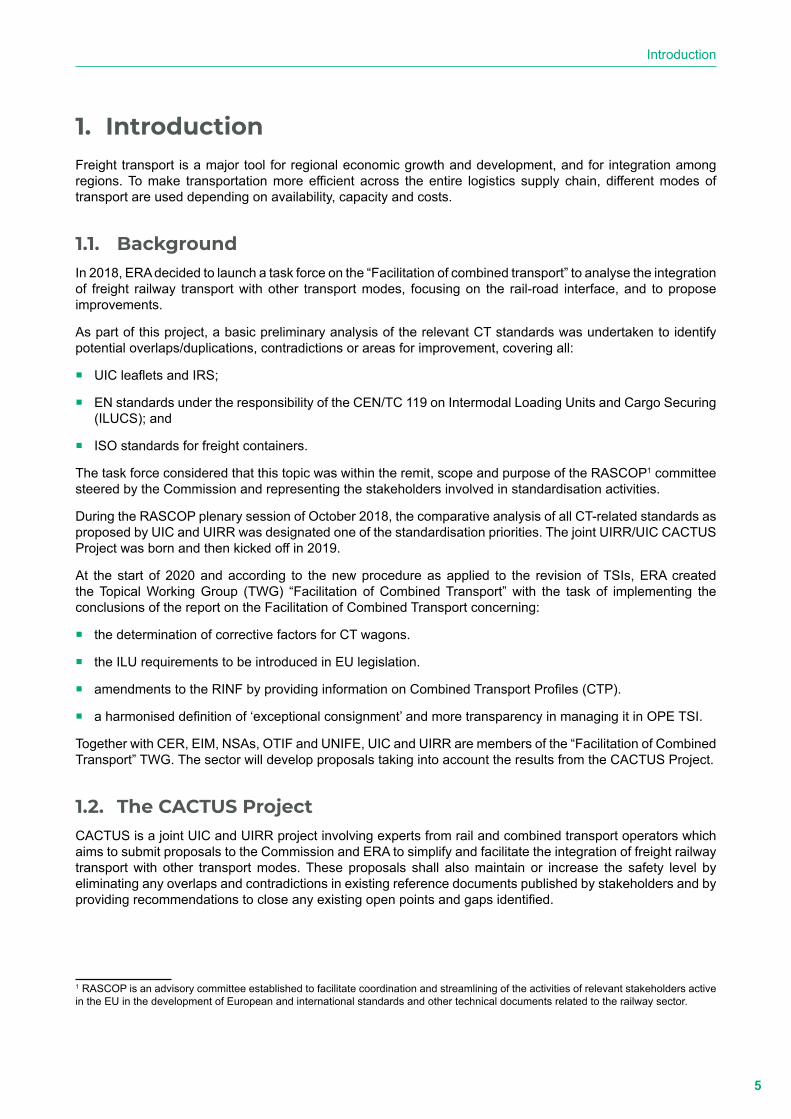
1. IntroductionFreight transport is a major tool for regional economic growth and development, and for integration among regions. To make transportation more efficient across the entire logistics supply chain, different modes of transport are used depending on availability, capacity and costs.
1.1. BackgroundIn 2018, ERA decided to launch a task force on the “Facilitation of combined transport” to analyse the integration of freight railway transport with other transport modes, focusing on the rail-road interface, and to propose improvements.
As part of this project, a basic preliminary analysis of the relevant CT standards was undertaken to identify potential overlaps/duplications, contradictions or areas for improvement, covering all:
� UIC leaflets and IRS;
� EN standards under the responsibility of the CEN/TC 119 on Intermodal Loading Units and Cargo Securing (ILUCS); and
� ISO standards for freight containers.
The task force considered that this topic was within the remit, scope and purpose of the RASCOP1 committee steered by the Commission and representing the stakeholders involved in standardisation activities.
During the RASCOP plenary session of October 2018, the comparative analysis of all CT-related standards as proposed by UIC and UIRR was designated one of the standardisation priorities. The joint UIRR/UIC CACTUS Project was born and then kicked off in 2019.
At the start of 2020 and according to the new procedure as applied to the revision of TSIs, ERA created the Topical Working Group (TWG) “Facilitation of Combined Transport” with the task of implementing the conclusions of the report on the Facilitation of Combined Transport concerning:
� the determination of corrective factors for CT wagons.
� the ILU requirements to be introduced in EU legislation.
� amendments to the RINF by providing information on Combined Transport Profiles (CTP).
� a harmonised definition of ‘exceptional consignment’ and more transparency in managing it in OPE TSI.
Together with CER, EIM, NSAs, OTIF and UNIFE, UIC and UIRR are members of the “Facilitation of Combined Transport” TWG. The sector will develop proposals taking into account the results from the CACTUS Project.
1.2. The CACTUS ProjectCACTUS is a joint UIC and UIRR project involving experts from rail and combined transport operators which aims to submit proposals to the Commission and ERA to simplify and facilitate the integration of freight railway transport with other transport modes. These proposals shall also maintain or increase the safety level by eliminating any overlaps and contradictions in existing reference documents published by stakeholders and by providing recommendations to close any existing open points and gaps identified.
1 RASCOP is an advisory committee established to facilitate coordination and streamlining of the activities of relevant stakeholders active in the EU in the development of European and international standards and other technical documents related to the railway sector.

6
Comparative analysis of the combined transport usages and standards (CACTUS) - Final Report
The analysis focuses on the requirements on:
� CT wagons designed for the conveyance of Intermodal Loading Units.
� ILUs designed for vertical and horizontal transhipment.
� lines on which combined trains can be operated without constraints.
The following experts are members of the CACTUS Project Team:
� Constanze BANNHOLZER (UIC Freight Department)
� Eric LAMBERT (Chairman of UIC SET 03)
� Stefano GUIDI (UIC Rail System Department)
� Eric FEYEN (UIRR - Technical Director)
� Louis BRUNEAU (UIRR - External expert)

7
Scope
2. ScopeThe primary aims of this comparative study are to:
� analyse the current standardisation ecosystem in combined transport;
� identify any possible overlaps, contradictions and gaps; and
� draw up recommendations.
The current final report has been structured as follows:
� Chapter 1 introduces the CACTUS project.
� Chapter 2 defines the scope and the overall structure of the report.
� Chapter 3 provides an overview of the UIC combined transport codification in accordance with IRS 50596-6.
� Chapters 4, 5 and 6 expand the analysis of the three different areas that are deemed relevant for combined transport:
y Combined transport wagons (Chapter 4)
y ILUs for vertical and horizontal transhipment (Chapter 5):
• Semi-trailers (Point 5.1.1)
• ISO containers (Point 5.1.2)
• ILUs other than semi-trailers and ISO containers, known as swap bodies or non- ISO containers (Point 5.1.3)
• Roller units (Point 5.2.1)
y Combined transport lines (Chapter 6).
The above-mentioned chapters and paragraphs are structured as follows:
1. Identification and overview of regulations, standards and guidelines.
2. Identification of overlaps, duplications and contradictions.
3. Identification of potential areas of improvement, cross-referencing and harmonisation needs.
Chapter 7 details the recommendations, based on the results of the comparative analysis, submitted by UIC and UIRR to the Commission, ERA and the stakeholders as a contribution to the facilitation of combined transport.

8
Comparative analysis of the combined transport usages and standards (CACTUS) - Final Report
3. Codification in combined transportCombined transport deals with the conveyance of Intermodal Loading Units (ILUs) by road, rail, inland waterways and short-sea shipping.
The dimensions of most ILUs (semi-trailers, swap bodies and roller units) are optimised for road transport and when forwarded on wagons, their upper sections exceed the standard loading gauge in terms of height in several European Member States in a relevant number of cases.
The most common solution is to use and apply the procedures for exceptional consignments according to UIC Leaflet 502-1. The nature of this procedure is cumbersome as it obliges railway undertakings to obtain specific authorisation from all involved infrastructure managers and to check the size of the ILUs when loaded on the wagons to ensure that they do not exceed the authorised dimensions.
The codification system as per IRS 50596-6 was established by UIC in collaboration with UIRR to facilitate and speed up the conveyance of ILUs in a reliable manner, even when their upper dimensions exceed those compatible with the loading gauge of the line (see Figure 1).
(Provided by Paolo Cavicchi - FSI/Mercitalia Rail)
Figure 1: Route Xxxx to Yyyy (Loading gauge G1, CTPn C/P 45) Comparison between the maximum upper dimensions of swap bodies which are permitted when a
line is classified G1 according to INF TSI and C45 according to IRS 50596-6.
The codification system as defined in IRS 50596-6 has been applied for several decades by various RUs and IMs in the combined transport chain and ensures the safe operation of ILUs loaded on compatible wagons when transported on codified lines. IRS 50596-6 provides the system requirements for:
� the allocation of the wagon compatibility code and correction digits to wagons;
9
Codification in combined transport
� the codification of ILUs;
� the codification of lines;
� the verification of compatibility between ILUs and wagons; and
� the assessment of compatibility between ILUs conveyed on suitable wagons and lines.
3.1. Allocation of the wagon compatibility codeILUs are conveyed on wagons which may be compatible with one or more types of ILU. The CT wagons currently used are as follows:
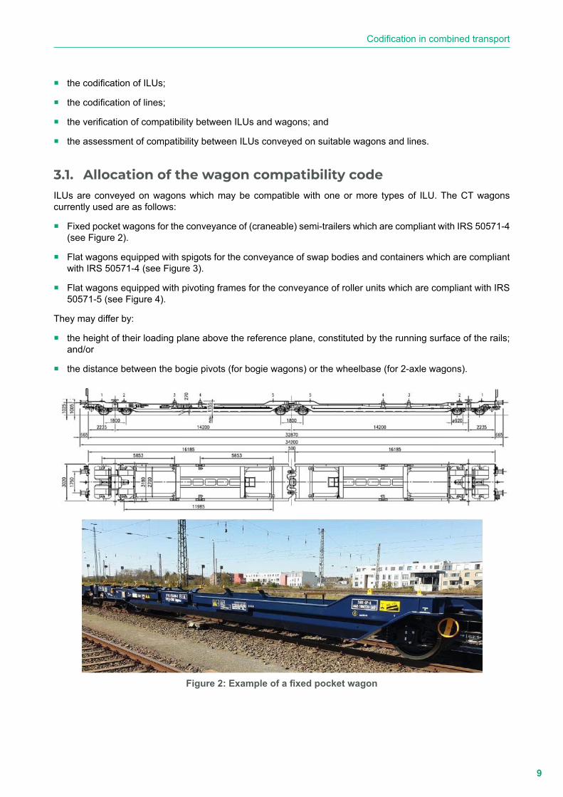
� Fixed pocket wagons for the conveyance of (craneable) semi-trailers which are compliant with IRS 50571-4 (see Figure 2).
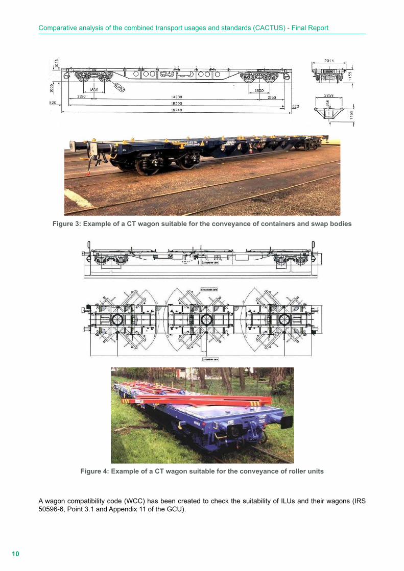
� Flat wagons equipped with spigots for the conveyance of swap bodies and containers which are compliant with IRS 50571-4 (see Figure 3).
� Flat wagons equipped with pivoting frames for the conveyance of roller units which are compliant with IRS 50571-5 (see Figure 4).
They may differ by:
� the height of their loading plane above the reference plane, constituted by the running surface of the rails; and/or
� the distance between the bogie pivots (for bogie wagons) or the wheelbase (for 2-axle wagons).
Figure 2: Example of a fixed pocket wagon
10
Comparative analysis of the combined transport usages and standards (CACTUS) - Final Report
Figure 3: Example of a CT wagon suitable for the conveyance of containers and swap bodies
Figure 4: Example of a CT wagon suitable for the conveyance of roller units
A wagon compatibility code (WCC) has been created to check the suitability of ILUs and their wagons (IRS 50596-6, Point 3.1 and Appendix 11 of the GCU).
11
Codification in combined transport
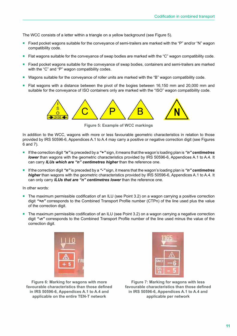
The WCC consists of a letter within a triangle on a yellow background (see Figure 5).
� Fixed pocket wagons suitable for the conveyance of semi-trailers are marked with the “P” and/or “N” wagon compatibility code.
� Flat wagons suitable for the conveyance of swap bodies are marked with the “C” wagon compatibility code.
� Fixed pocket wagons suitable for the conveyance of swap bodies, containers and semi-trailers are marked with the “C” and “P” wagon compatibility codes.
� Wagons suitable for the conveyance of roller units are marked with the “B” wagon compatibility code.
� Flat wagons with a distance between the pivot of the bogies between 16,150 mm and 20,000 mm and suitable for the conveyance of ISO containers only are marked with the “ISO” wagon compatibility code.
Figure 5: Example of WCC markings
In addition to the WCC, wagons with more or less favourable geometric characteristics in relation to those provided by IRS 50596-6, Appendices A.1 to A.4 may carry a positive or negative correction digit (see Figures 6 and 7).
� If the correction digit “n” is preceded by a “+” sign, it means that the wagon’s loading plan is “n” centimetres lower than wagons with the geometric characteristics provided by IRS 50596-6, Appendices A.1 to A.4. It can carry ILUs which are “n” centimetres higher than the reference one.
� If the correction digit “n” is preceded by a “-” sign, it means that the wagon’s loading plan is “n” centimetres higher than wagons with the geometric characteristics provided by IRS 50596-6, Appendices A.1 to A.4. It can only carry ILUs that are “n” centimetres lower than the reference one.
In other words:
� The maximum permissible codification of an ILU (see Point 3.2) on a wagon carrying a positive correction digit “+n” corresponds to the Combined Transport Profile number (CTPn) of the line used plus the value of the correction digit.
� The maximum permissible codification of an ILU (see Point 3.2) on a wagon carrying a negative correction digit “-n” corresponds to the Combined Transport Profile number of the line used minus the value of the correction digit.
Figure 6: Marking for wagons with more
favourable characteristics than those defined in IRS 50596-6, Appendices A.1 to A.4 and
applicable on the entire TEN-T network
Figure 7: Marking for wagons with less
favourable characteristics than those defined in IRS 50596-6, Appendices A.1 to A.4 and
applicable per network
12
Comparative analysis of the combined transport usages and standards (CACTUS) - Final Report
3.2. Codification of ILUsThe following ILUs can be conveyed on suitable wagons within the framework of codified combined transport:
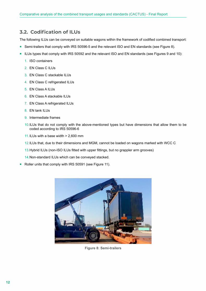
� Semi-trailers that comply with IRS 50596-5 and the relevant ISO and EN standards (see Figure 8).
� ILUs types that comply with IRS 50592 and the relevant ISO and EN standards (see Figures 9 and 10):
1. ISO containers
2. EN Class C ILUs
3. EN Class C stackable ILUs
4. EN Class C refrigerated ILUs
5. EN Class A ILUs
6. EN Class A stackable ILUs
7. EN Class A refrigerated ILUs
8. EN tank ILUs
9. Intermediate frames
10. ILUs that do not comply with the above-mentioned types but have dimensions that allow them to be coded according to IRS 50596-6
11. ILUs with a base width ˃ 2,600 mm
12. ILUs that, due to their dimensions and MGM, cannot be loaded on wagons marked with WCC C
13. Hybrid ILUs (non-ISO ILUs fitted with upper fittings, but no grappler arm grooves)
14. Non-standard ILUs which can be conveyed stacked.
� Roller units that comply with IRS 50591 (see Figure 11).
Figure 8: Semi-trailers

13
Codification in combined transport
Figure 9: Containers
Figure 10: Swap bodies
Figure 11: Roller units
14
Comparative analysis of the combined transport usages and standards (CACTUS) - Final Report
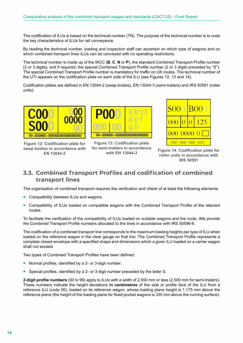
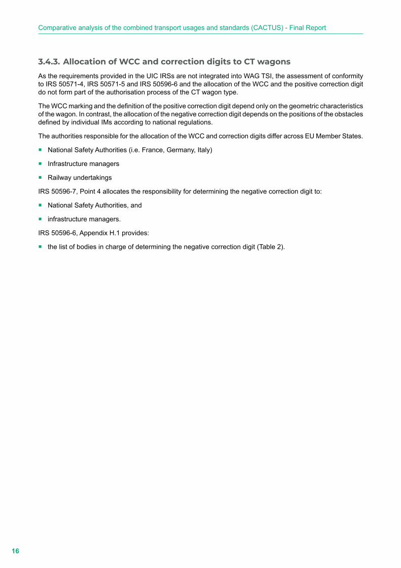
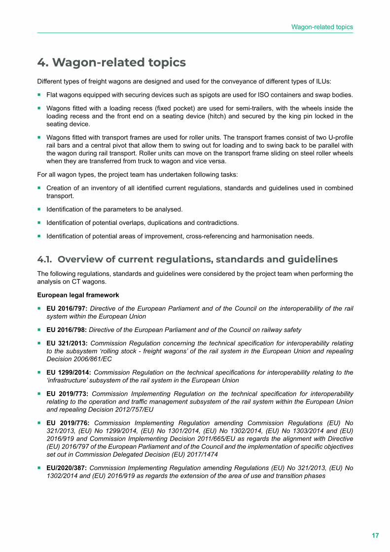
The codification of ILUs is based on the technical number (TN). The purpose of the technical number is to code the key characteristics of ILUs for rail conveyance.
By reading the technical number, loading and inspection staff can ascertain on which type of wagons and on which combined transport lines ILUs can be conveyed with no operating restrictions.
The technical number is made up of the WCC (B, C, N or P), the standard Combined Transport Profile number (2 or 3 digits), and if required, the special Combined Transport Profile number (2 or 3 digits preceded by “S”). The special Combined Transport Profile number is mandatory for traffic on UK routes. The technical number of the UTI appears on the codification plate on each side of the ILU (see Figures 12, 13 and 14).
Codification plates are defined in EN 13044-2 (swap bodies), EN 13044-3 (semi-trailers) and IRS 50591 (roller units):
Figure 12: Codification plate for swap bodies in accordance with
EN 13044-2
Figure 13: Codification plate
for semi-trailers in accordance with EN 13044-3
Figure 14: Codification plate for roller units in accordance with
IRS 50591
3.3. Combined Transport Profiles and codification of combined transport lines
The organisation of combined transport requires the verification and check of at least the following elements:
� Compatibility between ILUs and wagons.
� Compatibility of ILUs loaded on compatible wagons with the Combined Transport Profile of the relevant routes.
To facilitate the verification of the compatibility of ILUs loaded on suitable wagons and the route, IMs provide the Combined Transport Profile numbers allocated to the lines in accordance with IRS 50596-6.
The codification of a combined transport line corresponds to the maximum loading heights per type of ILU when loaded on the reference wagon in the clear gauge on that line. The Combined Transport Profile represents a complete closed envelope with a specified shape and dimensions which a given ILU loaded on a carrier wagon shall not exceed.
Two types of Combined Transport Profiles have been defined:
� Normal profiles, identified by a 2- or 3-digit number.
� Special profiles, identified by a 2- or 3-digit number preceded by the letter S.
2-digit profile numbers (00 to 99) apply to ILUs with a width of 2,550 mm or less (2,500 mm for semi-trailers). These numbers indicate the height deviations in centimetres of the side or profile face of the ILU from a reference ILU (code 00), loaded on its reference wagon, whose loading plane height is 1,175 mm above the reference plane (the height of the loading plane for fixed-pocket wagons is 330 mm above the running surface).

15
Codification in combined transport
3-digit profile numbers (330 to 429) apply to ILUs with a width greater than 2,550 mm and less than or equal to 2,600 mm (between 2,500 mm and 2,600 mm for semi-trailers). These numbers indicate the total height in centimetres of the top angle of the side face of the ILU loaded on its reference wagon, in relation to the reference plane.
Examples:
The numbered profile 22 allows a height of 22 cm higher than the minimum profile (coded 00) for swap bodies and roller units up to 2,550 mm wide.
According to IRS 50596-6, Appendix C.1, the minimum profile 00 for swap bodies and roller units up to a maximum width of 2,550 mm corresponds to a height of the top angle of the side face of the ILU of 330 cm from the reference plane. Profile 22 allows an additional 22 cm in height, corresponding to a height of the top angle of the side face of the ILU of 352 cm.
The numbered profile 341 allows for swap bodies and roller units with a width of more than 2,550 mm and less than or equal to 2,600 mm to be 11 cm higher than the minimum profile.
According to IRS 50696-6, Appendix C.2, the minimum profile 330 for swap bodies and roller units with a width greater than 2,550 mm and less than or equal to 2,600 mm corresponds to a height of the top angle of the side face of the ILU of 330 cm in relation to the reference plane. Profile 341 allows an additional 11 cm in height, corresponding to a height of the top angle of the side face of the ILU of 341 cm.
3.4. Identification of the entities in charge of coding CT lines, approving and coding ILUs, and allocating the WCC and correction digits to CT wagons
IRS 50596-7 defines the roles, responsibilities and requirements of the entity in charge of coding CT lines, approving and coding ILUs, and allocating the WCC and correction digits to CT wagons.
3.4.1. Coding CT lines
IRS 50596-7, Point 3 allocates the responsibility for CT line coding as per IRS 50596-6 to the IMs involved for each combined transport line.
3.4.2. Approving and coding ILUs
IRS 50596-7, Point 4 allocates the responsibility for approving and coding ILUs to:
� National Safety Authorities,
� infrastructure managers,
� freight railway undertakings, and
� subjects delegated by the above-mentioned entities.
IRS 50596-7, Point 4.2 lists the requirements for entities charged with performing ILU type approval and coding.
IRS 50596-6, Appendix H.1 provides:
� the list and codes of bodies recognised by UIC to grant ILU codification (Table 1); and
� the list of bodies in charge of ILU approval, ILU coding and coding plate delivery (Table 2).
16
Comparative analysis of the combined transport usages and standards (CACTUS) - Final Report
3.4.3. Allocation of WCC and correction digits to CT wagons
As the requirements provided in the UIC IRSs are not integrated into WAG TSI, the assessment of conformity to IRS 50571-4, IRS 50571-5 and IRS 50596-6 and the allocation of the WCC and the positive correction digit do not form part of the authorisation process of the CT wagon type.
The WCC marking and the definition of the positive correction digit depend only on the geometric characteristics of the wagon. In contrast, the allocation of the negative correction digit depends on the positions of the obstacles defined by individual IMs according to national regulations.
The authorities responsible for the allocation of the WCC and correction digits differ across EU Member States.
� National Safety Authorities (i.e. France, Germany, Italy)
� Infrastructure managers
� Railway undertakings
IRS 50596-7, Point 4 allocates the responsibility for determining the negative correction digit to:
� National Safety Authorities, and
� infrastructure managers.
IRS 50596-6, Appendix H.1 provides:
� the list of bodies in charge of determining the negative correction digit (Table 2).
17
Wagon-related topics
4. Wagon-related topicsDifferent types of freight wagons are designed and used for the conveyance of different types of ILUs:
� Flat wagons equipped with securing devices such as spigots are used for ISO containers and swap bodies.
� Wagons fitted with a loading recess (fixed pocket) are used for semi-trailers, with the wheels inside the loading recess and the front end on a seating device (hitch) and secured by the king pin locked in the seating device.
� Wagons fitted with transport frames are used for roller units. The transport frames consist of two U-profile rail bars and a central pivot that allow them to swing out for loading and to swing back to be parallel with the wagon during rail transport. Roller units can move on the transport frame sliding on steel roller wheels when they are transferred from truck to wagon and vice versa.
For all wagon types, the project team has undertaken following tasks:
� Creation of an inventory of all identified current regulations, standards and guidelines used in combined transport.
� Identification of the parameters to be analysed.
� Identification of potential overlaps, duplications and contradictions.
� Identification of potential areas of improvement, cross-referencing and harmonisation needs.
4.1. Overview of current regulations, standards and guidelinesThe following regulations, standards and guidelines were considered by the project team when performing the analysis on CT wagons.
European legal framework
� EU 2016/797: Directive of the European Parliament and of the Council on the interoperability of the rail system within the European Union
� EU 2016/798: Directive of the European Parliament and of the Council on railway safety
� EU 321/2013: Commission Regulation concerning the technical specification for interoperability relating to the subsystem ‘rolling stock - freight wagons’ of the rail system in the European Union and repealing Decision 2006/861/EC
� EU 1299/2014: Commission Regulation on the technical specifications for interoperability relating to the ‘infrastructure’ subsystem of the rail system in the European Union
� EU 2019/773: Commission Implementing Regulation on the technical specification for interoperability relating to the operation and traffic management subsystem of the rail system within the European Union and repealing Decision 2012/757/EU
� EU 2019/776: Commission Implementing Regulation amending Commission Regulations (EU) No 321/2013, (EU) No 1299/2014, (EU) No 1301/2014, (EU) No 1302/2014, (EU) No 1303/2014 and (EU) 2016/919 and Commission Implementing Decision 2011/665/EU as regards the alignment with Directive (EU) 2016/797 of the European Parliament and of the Council and the implementation of specific objectives set out in Commission Delegated Decision (EU) 2017/1474
� EU/2020/387: Commission Implementing Regulation amending Regulations (EU) No 321/2013, (EU) No 1302/2014 and (EU) 2016/919 as regards the extension of the area of use and transition phases

18
Comparative analysis of the combined transport usages and standards (CACTUS) - Final Report
� EU 1304/2014: Commission Regulation on the technical specification for interoperability relating to the subsystem ‘rolling stock - noise’ amending Decision 2008/232/EC and repealing Decision 2011/229/EU
� EU 2019/774: Commission implementing Regulation amending Regulation EU 1304/2014 as regards application of the technical specification for interoperability relating to the subsystem ‘rolling stock - noise’ to the existing freight wagons
� EU 445/2011: Commission Regulation on a system of certification of entities in charge of maintenance for freight wagons and amending Regulation (EC) No 653/2007
United Nations Economic Commission for Europe (UNECE)
� Regulation No. 55: Uniform provisions concerning the approval of mechanical coupling components of combinations of vehicles, Ed. 2018
International Union of Railways (UIC)
� IRS 50571-4: Wagons for combined transport - Vertical transhipment - Characteristics
� IRS 50571-5: Wagons for combined transport - Roller units for horizontal transhipment - Characteristics
� IRS 50596-6: Conditions for coding intermodal loading units in combined transport, combined transport lines and wagons, Ed. 2018
� IRS 50596-7: Railway Application - Rolling Stock - Conformity Assessment - Requirements for bodies performing the certification of coding in accordance with UIC Leaflet 596-6 (Competent Authorities), Ed. 2017
� UIC Leaflet 502-1: Exceptional consignments - Regulations concerning the preparation and management of exceptional consignments, Ed. 2016
� UIC Leaflet 572: Wagons composed of permanently coupled units (multiple wagons) and articulated wagons, Ed. 2011
� UIC Leaflet 430-1: Conditions with which wagons must comply in order to be accepted for transit between standard gauge railways and the Spanish and Portuguese broad-gauge railways, Ed. 2012
� UIC Leaflet 430-3: Freight wagons - Technical conditions for freight wagons capable of running on both standard-gauge and Finnish broad-gauge systems, Ed. 1995
� UIC Leaflet 535-2: Standardisation and positioning on wagons of steps, end platforms, gangways, handrails, tow hooks, automatic coupler (AC), automatic draw-on coupling and brake valve controls on the UIC member RUs and OSJD member RUs, Ed. 2006
� UIC Leaflet 575: Wagons - Label holders (Interchangeability) and hazard identification panels, Ed. 1996
� UIC Leaflet 540: Brakes - Air Brakes for freight trains and passenger trains, Ed. 2006
� UIC Leaflet 541-1: Brakes - Regulations concerning the design of brake components, Ed. 2014
� UIC Leaflet 541-4: Brakes - Composite brake blocks - General conditions for certification and use, Ed. 2010
� UIC Leaflet 542: Brake parts - Interchangeability, Ed. 2015
� UIC Leaflet 544-1: Brakes - Braking performance, Ed. 2014
� Loading Guidelines, Volume 1: Code of practice for the loading and securing of goods on railway wagons - Principles, Ed. 2020
� Loading Guidelines, Volume 2: Code of practice for the loading and securing of goods on railway wagons - Goods, Ed. 2020
19
Wagon-related topics
GCU Bureau
� GCU: General Contract for Use of wagons, Ed. 2020
European Union Agency for Railways (ERA)
� ERA/TD/2012-04/INT: Attachment devices for rear-end signals, clearance for draw hooks, space for shunting staff operation, footsteps and handrails - Version 1.0, Ed. 2012
� ERA/ TD/2013-02/INT: Friction elements for wheel tread brakes for freight wagons - Version 3.0, Ed. 2015
� ERA/ERTMS/033281: Interfaces between control-command and signalling trackside and other subsystems - rev. 4, Ed. 2018
European Committee for Standardization (CEN)
� EN 15551: Railway applications - Railway rolling stock - Buffers, Ed. 2009 + A1, Ed. 2010
� EN 15566: Railway applications - Railway rolling stock - Draw gear and screw coupling, Ed. 2009 + A1, Ed. 2010
� EN 16116-2: Railway applications - Design requirements for steps, handrails and associated access for staff - Part 2: Freight wagons, Ed. 2013
� EN 12663-1: Railway applications - Structural requirements of railway vehicle bodies - Part 1: Locomotives and passenger rolling stock (and alternative method for freight wagons), Ed. 2010 + A1, Ed. 2010
� EN 12663-2: Railway applications - Structural requirements of railway vehicle bodies - Part 2: Freight wagons, Ed. 2010
� EN 15877-1: Railway applications - Marking on railway vehicles - Part 1: Freight wagons, Ed. 2012
� EN 15273-2: Railway applications - Gauges - Part 2: Rolling stock gauge, Ed. 2013
� EN 15528: Railway applications - Line categories for managing the interface between load limits of vehicles and infrastructure, Ed. 2008
� EN 15437-1: Railway applications - Axle box condition monitoring - Interface and design requirements - Part 1: Track side equipment and rolling stock axle box, Ed. 2009
� EN 14363: Railway applications - Testing and simulation for the acceptance of running characteristics of railway vehicles - Running behaviour and stationary tests, Ed. 2016
� EN 15839: Railway applications - Testing for the acceptance of running characteristics of railway vehicles - Freight wagons - Testing of running safety under longitudinal compressive forces, Ed. 2012
� EN 15687: Railway applications - Testing for the acceptance of running characteristics of freight vehicles with static axle loads higher than 225 kN and up to 250 kN, Ed. 2010
� EN 15827: Railway applications - Requirements for bogies and running gears, Ed. 2011
� EN 16235: Railway applications - Testing for the acceptance of running characteristics of railway vehicles - Freight wagons - Conditions for dispensation of freight wagons with defined characteristics from on-track tests according to EN 14363, Ed. 2013
� EN 13749: Railway applications - Wheelsets and bogies - Method of specifying the structural requirements of bogie frames, Ed. 2011
� EN 13260: Railway applications - Wheelsets and bogies - Wheelsets - Product requirements, Ed. 2009 + A1, Ed. 2010
� EN 13979-1: Railway applications - Wheelsets and bogies - Monobloc wheels - Technical approval procedure - Part 1: Forged and rolled wheels, Ed. 2003+ A1, Ed. 2009 + A2, Ed. 2011
20
Comparative analysis of the combined transport usages and standards (CACTUS) - Final Report
� EN 13262: Railway applications - Wheelsets and bogies - Wheels - Product requirements, Ed. 2004
� EN 13103: Railway applications - Wheelsets and bogies - Part 1: Design method for axles with external journals, Ed. 2009 + A1, Ed. 2010
� EN 12082: Railway applications - Axle boxes - Performance testing, Ed. 2007 + A1, Ed. 2010
� EN 15355: Railway applications - Braking - Distributor valves and distributor-isolating devices, Ed. 2008 + A1, Ed. 2010
� EN 15611: Railway applications - Braking - Relay valves, Ed. 2008 + A1, 2010
� EN 15624: Railway applications - Braking - Empty-loaded changeover devices, Ed. 2008 + A1, 2010
� EN 15625: Railway applications - Braking - Automatic variable load sensing devices, Ed. 2008 + A1, 2010
� EN 15807: Railway applications - Pneumatic half couplings, Ed. 2011
� EN 286-3: Simple unfired pressure vessels designed to contain air or nitrogen - Part 3: Steel pressure vessels designed for air braking equipment and auxiliary pneumatic equipment for railway rolling stock, Ed. 1994
� EN 286-4: Simple unfired pressure vessels designed to contain air or nitrogen - Part 4: Aluminium alloy pressure vessels designed for air braking equipment and auxiliary pneumatic equipment for railway rolling stock, Ed. 1994
� EN 14601: Railway applications - Straight and angled end cocks for brake pipe and main reservoir pipe, Ed. 2005 + A1, Ed. 2010
� EN 15595: Railway applications - Braking - Wheel slide protection, Ed. 2009 + A1, Ed. 2011
� EN 14531-1: Railway applications - Methods for calculation of stopping and slowing distances and immobilization braking - Part 1: General algorithms utilizing mean value calculation for train sets or single vehicles, Ed. 2015
� EN 14531-6: Railway applications - Methods for calculation of stopping and slowing distances and immobilisation braking - Part 6: step by step calculations for train sets or single vehicles, Ed. 2009
� EN 50125-1: Railway applications - Environmental conditions for equipment - Part 1: rolling stock and on-board equipment, Ed. 2009
� EN 1363-1: Fire resistance tests - Part 1: General requirements, Ed. 2012
� EN13501-1: Fire classification of construction products and building elements - Part 1: Classification using data from reaction to fire tests, Ed. 2007 + A1, Ed. 2009
� EN 50355: Railway applications - Railway rolling stock cables having special fire performance - Guide to use, Ed. 2013
� EN 50343: Railway applications - Rolling stock - Rules for installation of cabling, Ed. 2014
� EN 45545-2: Railway applications - Fire protection on railway vehicles - Part 2: Requirements for fire behaviour of materials and components, Ed. 2015
� EN 45545-7: Railway applications - Fire protection on railway vehicles - Part 7: fire safety requirements on flammable liquid and flammable gas installations, Ed. 2009
� EN 15085 -1: Railway applications - Welding of railway vehicles and components - Part 1: General part, Ed. 2007 + A1: 2013
� EN 15085 -2 to 5: Railway applications - Welding of railway vehicles and components - Part 2: Requirements for welding manufacturer / Part 3: Design requirements / Part 4: Production requirements / Part 5: Inspection, testing and documentation, Ed. 2007

21
Wagon-related topics
� EN 50153: Railway applications. Rolling stock. Protective provisions relating to electrical hazards, Ed. 2015
International Organization for Standardization (ISO)
� ISO 5658-2: Reaction to fire tests - Spread of flame - Part 2: Lateral spread on building and transport products in vertical configuration, Ed. 2006 + AMD1, Ed. 2011
� ISO 5660-1: Reaction-to-fire tests - Heat release, smoke production and mass loss rate - Part 1: Heat release rate (cone calorimeter method) and smoke production rate (dynamic measurement), Ed. 2015
4.2. Overlaps, duplications and contradictionsThe goal of the comparative analysis of the documents listed in Point 4.1 is the identification of:
� the requirements provided by each document for selected parameters;
� overlaps, duplications and contradictions; and
� potential areas of improvement, cross-referencing and harmonisation needs (see Point 4.3).
a. Parameters and items
The analysis is focused on the following parameters:
1 Definitions
1000 General
1001 Interoperability essential requirements and functional and technical specifications
1002 Payload
1002.1 Axle load
1002.2 Minimum axle load
1003 Structural requirements of wagon bodies
1004 Braking equipment
1005 Shunting conditions
1006 Buffer and coupling
1007 Digital Automatic Coupling
1008 Conveyance of wagons on ferries
1100 Specific parameters for wagons for the conveyance of semi-trailers (verticaltranshipment)
1101 Loading position of the semi-trailer
1102 Wagon envelope
1102.1 Dimensions
1102.2 Compatibility with the semi-trailer envelope
1103 Intermediate support
1104 Seating device
1104.1 Position
1104.2 Height
1104.3 Width
1104.4 Compatibility with the semi-trailer king pin

22
Comparative analysis of the combined transport usages and standards (CACTUS) - Final Report
1104.5 Compatibility with the semi-trailer steering wedge
1104.6 Locking device
1104.7 Visibility of the locking state during the conveyance of semi-trailers
1105 Bearing plates
1105.1 Dimensions
1105.2 Location
1200 Specific parameters for wagons for the conveyance of ISO containers and swap bodies (vertical transhipment)
1201 Spigots
1201.1 Types
1201.2 Shape, dimensions and positioning
1201.3 Strength
1201.4 Tests
1202 Supports for the load transfer areas of containers and swap bodies
1300 Specific parameters for wagons for the conveyance of roller units (horizontal transhipment)
1301 Pivoting frames
1302 Systems for securing and blocking roller units
1302.1 Locking system
1302.2 Stoppers
1303 Tests
1303.1 Test requirements for wagons and for intermediary underframes with pivoting frames
1303.2 Supplementary impact tests for pivoting frames and pivoting frames on intermediary underframes
1303.3 Static tests for pivoting frames and pivoting frames on intermediary underframes
1400 Parameters linked to the WCC allocation
1401 Height of the loading plane
1402 Bogie wagons: distance between pivots
1403 2-axle wagons: wagon wheelbase
1404 Overhang
1405 Bogie wheelbase
1406 Side bearers
1406.1 Side bearers play (j)
1406.2 Half-distance between side bearers (bG)
1407 Total lateral play (q+w)
1408 Vehicle flexibility coefficient (s)
1409 Dissymmetry (η0)
1410 Height of the roll centre
1411 Tolerances (centring)
1411.1 Tolerances to the right of the tyres

23
Wagon-related topics
1411.2 Tolerances to the right of the king pin
1411.3 Tolerances to the right of the spigots
300 Identification and markings
300.1 Identification
300.2 Operational markings
400 Maintenance
500 Operational control
600 Certification
600.4 Vehicle type authorisation
700 Route compatibility assessment
700.1 Allocation of correction digits
b. Results of the analysis
This point provides a summary of the results of the dry and comparative analysis. It is focused on the identification of the requirements on each parameter that are provided by the reference documents, highlighting:
� requirements which are provided in a reference document and not considered in IRS 50571-4, IRS 50571-5 and IRS 50596-6.
� requirements which are provided in IRS 50571-4, IRS 50571-5 and IRS 50596-6 and not considered in the rest of the reference documents.
� contradictions between the requirements provided by the different reference documents.
� requirements that are not provided by any reference document and need to be implemented.
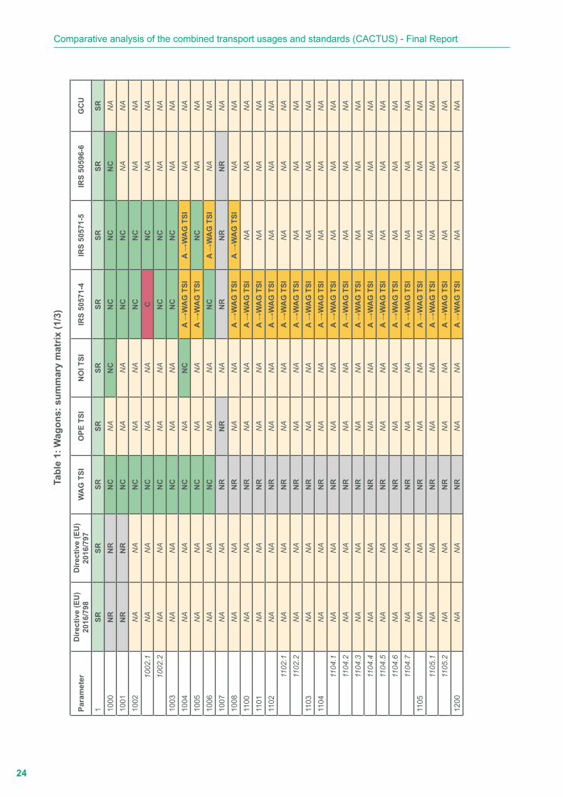
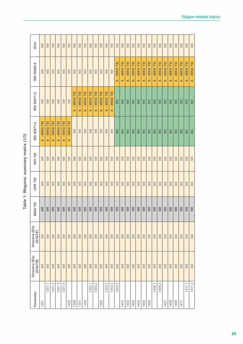
b.1. Summary (matrix table)
Table 1 provides a matrix compiling the parameters and the analysed reference documents.
� Requirements which are provided by each reference document with no contradictions are identified by the
following marking in a green box: NC
� Contradictions between requirements provided by the relevant reference documents are identified by the
following marking in a red box: C
� Specific requirements provided by a reference document are identified by the following marking in a green
box: SR
� Requirements which are not considered in the relevant reference documents are identified by the following
marking in a yellow box: A → EU 20XX/YY
� Requirements that are not considered in the relevant reference documents are identified by the following
marking in a grey box: NR
� Requirements which are out of the scope of the relevant documents are identified by the following marking
in a light brown box: NA
24
Comparative analysis of the combined transport usages and standards (CACTUS) - Final Report
Tabl
e 1:
Wag
ons:
sum
mar
y m
atrix
(1/3
)
Para
met
erD
irect
ive
(EU
) 20
16/7
98D
irect
ive
(EU
) 20
16/7
97W
AG
TSI
OPE
TSI
NO
I TSI
IRS
5057
1-4
IRS
5057
1-5
IRS
5059
6-6
GC
U
1SR
SRSR
SRSR
SRSR
SRSR
1000
NR
NR
NC
NA
NC
NC
NC
NC
NA
1001
NR
NR
NC
NA
NA
NC
NC
NA
NA
1002
NA
NA
NC
NA
NA
NC
NC
NA
NA
1002
.1N
AN
AN
CN
AN
AC
NC
NA
NA
1002
.2N
AN
AN
CN
AN
AN
CN
CN
AN
A10
03N
AN
AN
CN
AN
AN
CN
CN
AN
A10
04N
AN
AN
CN
AN
CA
→W
AG
TSI
A →
WA
G T
SIN
AN
A10
05N
AN
AN
CN
AN
AA
→W
AG
TSI
NC
NA
NA
1006
NA
NA
NC
NA
NA
NC
A →
WA
G T
SIN
AN
A10
07N
AN
AN
RN
RN
AN
RN
RN
RN
A10
08N
AN
AN
RN
AN
AA
→W
AG
TSI
A →
WA
G T
SIN
AN
A11
00N
AN
AN
RN
AN
AA
→W
AG
TSI
NA
NA
NA
1101
NA
NA
NR
NA
NA
A →
WA
G T
SIN
AN
AN
A11
02N
AN
AN
RN
AN
AA
→W
AG
TSI
NA
NA
NA
1102
.1N
AN
AN
RN
AN
AA
→W
AG
TSI
NA
NA
NA
1102
.2N
AN
AN
RN
AN
AA
→W
AG
TSI
NA
NA
NA
1103
NA
NA
NR
NA
NA
A →
WA
G T
SIN
AN
AN
A11
04N
AN
AN
RN
AN
AA
→W
AG
TSI
NA
NA
NA
1104
.1N
AN
AN
RN
AN
AA
→W
AG
TSI
NA
NA
NA
1104
.2N
AN
AN
RN
AN
AA
→W
AG
TSI
NA
NA
NA
1104
.3N
AN
AN
RN
AN
AA
→W
AG
TSI
NA
NA
NA
1104
.4N
AN
AN
RN
AN
AA
→W
AG
TSI
NA
NA
NA
1104
.5N
AN
AN
RN
AN
AA
→W
AG
TSI
NA
NA
NA
1104
.6N
AN
AN
RN
AN
AA
→W
AG
TSI
NA
NA
NA
1104
.7N
AN
AN
RN
AN
AA
→W
AG
TSI
NA
NA
NA
1105
NA
NA
NR
NA
NA
A →
WA
G T
SIN
AN
AN
A11
05.1
NA
NA
NR
NA
NA
A →
WA
G T
SIN
AN
AN
A11
05.2
NA
NA
NR
NA
NA
A →
WA
G T
SIN
AN
AN
A12
00N
AN
AN
RN
AN
AA
→W
AG
TSI
NA
NA
NA
25
Wagon-related topics
Tabl
e 1:
Wag
ons:
sum
mar
y m
atrix
(1/3
)
Para
met
erD
irect
ive
(EU
) 20
16/7
98D
irect
ive
(EU
) 20
16/7
97W
AG
TSI
OPE
TSI
NO
I TSI
IRS
5057
1-4
IRS
5057
1-5
IRS
5059
6-6
GC
U
1201
NA
NA
NR
NA
NA
A →
WA
G T
SIN
AN
AN
A12
01.1
NA
NA
NR
NA
NA
A →
WA
G T
SIN
AN
AN
A12
01.2
NA
NA
NR
NA
NA
A →
WA
G T
SIN
AN
AN
A12
01.3
NA
NA
NR
NA
NA
A →
WA
G T
SIN
AN
AN
A12
01.4
NA
NA
NR
NA
NA
A →
WA
G T
SIN
AN
AN
A12
02N
AN
AN
RN
AN
AA
→W
AG
TSI
NA
NA
NA
1300
NA
NA
NR
NA
NA
NA
A →
WA
G T
SIN
AN
A13
01N
AN
AN
RN
AN
AN
AA
→W
AG
TSI
NA
NA
1302
NA
NA
NR
NA
NA
NA
A →
WA
G T
SIN
AN
A13
02.1
NA
NA
NR
NA
NA
NA
A →
WA
G T
SIN
AN
A13
02.2
NA
NA
NR
NA
NA
NA
A →
WA
G T
SIN
AN
A13
03N
AN
AN
RN
AN
AN
AA
→W
AG
TSI
NA
NA
1303
.1N
AN
AN
RN
AN
AN
AA
→W
AG
TSI
NA
NA
1303
.2N
AN
AN
RN
AN
AN
AA
→W
AG
TSI
NA
NA
1303
.3N
AN
AN
RN
AN
AN
CN
CA
→W
AG
TSI
NA
1401
NA
NA
NR
NA
NA
NC
NC
A →
WA
G T
SIN
A14
02N
AN
AN
RN
AN
AN
CN
CA
→W
AG
TSI
NA
1403
NA
NA
NR
NA
NA
NC
NC
A →
WA
G T
SIN
A14
04N
AN
AN
RN
AN
AN
CN
CA
→W
AG
TSI
NA
1405
NA
NA
NR
NA
NA
NC
NC
A →
WA
G T
SIN
A14
06N
AN
AN
RN
AN
AN
CN
CA
→W
AG
TSI
NA
1406
.1N
AN
AN
RN
AN
AN
CN
CA
→W
AG
TSI
NA
1406
.2N
AN
AN
RN
AN
AN
CN
CA
→W
AG
TSI
NA
1407
NA
NA
NR
NA
NA
NC
NC
A →
WA
G T
SIN
A14
08N
AN
AN
RN
AN
AN
CN
CA
→W
AG
TSI
NA
1409
NA
NA
NR
NA
NA
NC
NC
A →
WA
G T
SIN
A14
11N
AN
AN
RN
AN
AN
CN
CA
→W
AG
TSI
NA
1411
.1N
AN
AN
RN
AN
AN
CN
CA
→W
AG
TSI
NA
1411
.2N
AN
AN
RN
AN
AN
CN
CA
→W
AG
TSI
NA

26
Comparative analysis of the combined transport usages and standards (CACTUS) - Final Report
Tabl
e 1:
Wag
ons:
sum
mar
y m
atrix
(3/3
)
Para
met
erD
irect
ive
(EU
) 20
16/7
98D
irect
ive
(EU
) 20
16/7
97W
AG
TSI
OPE
TSI
NO
I TSI
IRS
5057
1-4
IRS
5057
1-5
IRS
5059
6-6
GC
U
300
NA
NA
SRSR
NA
SRSR
SRSR
300.
1N
AN
AN
RSR
NA
NR
NR
NR
NR
300.
2N
AN
ASR
NC
NA
A →
WA
G T
SIA
→W
AG
TSI
NC
NC
400
NC
NC
NC
NR
NC
NA
NA
NA
NC
500
SRN
CN
CN
CN
CN
AN
AN
AN
C60
0N
RN
CSR
NR
NA
NA
NA
NA
NA
600.
4N
CSR
NC
NC
NC
NA
NA
NA
NA
700
NC
NC
NC
NC
NC
NA
NA
NC
NC
700.
1N
RN
RN
RN
RN
AN
CN
CA
→W
AG
TSI
NC

27
Wagon-related topics
b.2. Summary of the outputs of the performed analysisThe following section describes in detail - for each parameter - the requirements provided by the reference documents highlighting any contradictions, overlaps and possible gaps. For ease of reading, a comprehensive description of each parameter has been added.
� Definitions (Parameter 1)
Definitions of wagons and wagon-related items are provided by all the technical documents listed in Point 4.1 of this report.
Due to the large number of technical documents involved, the search for appropriate definitions is difficult, and overlaps between definitions given by different standards are possible.
A single standard providing a complete set of definitions does not exist.
� General (Parameter 1000)
Wagons used for the conveyance of ILUs (CT wagons), like all types of wagons, shall be compliant with the requirements provided by WAG TSI and NOI TSI.
y WAG TSI applies to:
• wagons with a maximum operating speed lower than or equal to 160 km/h and a maximum axle load lower than or equal to 25 t.
• wagons which are intended to be operated on one or more of the following nominal track gauges: 1,435 mm, 1,524 mm, 1,600 mm and 1,668 mm (it does not apply to wagons operating mainly on the 1,520 mm track gauge, which may occasionally be operated on 1,524 mm track gauge).
y NOI TSI sets out the optimal level of harmonisation related to specifications on the rolling stock subsystem intended to limit the noise emission of the rail system within the European Union. It applies to new and existing wagons, within the scope of WAG TSI (including vehicles designed to carry lorries), which are designed for being used on railway infrastructure designated as quieter routes.2
According to Article 5a of the Commission Implementing Regulation (EU) 2019/774 of 16 May 2019 amending Regulation (EU) No 1304/2014 as regards application of the technical specification for interoperability relating to the subsystem ‘rolling stock - noise’ to the existing freight wagons, from 8 December 2024 wagons within the scope of Regulation (EU) No 321/2013 which are not covered by Point 7.2.2.2 of the Annex to this Regulation shall not be operated on the quieter routes.
Point 7.2.2.2: Wagons operated on quieter routes
Wagons belonging to one of the categories below can be operated on the quieter routes within their area of use:
� Wagons holding an EC declaration of verification against Commission Decision 2006/66/EC concerning the technical specification for interoperability relating to the subsystem ‘rolling stock noise’ of the trans-European conventional rail system;
� Wagons holding an EC declaration of verification against Commission Decision 2011/229/EU concerning the technical specifications of interoperability relating to the subsystem ‘rolling stock noise’ of the trans-European conventional rail system;
� Wagons holding an EC declaration of verification against this TSI;
� Wagons fitted with quieter brake blocks as defined in Point 7.2.2.1 or brake discs for the service brake function;
2 A quieter route means a part of the railway infrastructure with a minimum length of 20 km on which the average number of daily operated freight trains during the nighttime as defined in national legislation transposing Directive 2002/49/EC of the European Parliament and of the Council was higher than 12. The freight traffic in the years 2015, 2016 and 2017 shall be the basis for the calculation of that average number. In case the freight traffic due to exceptional circumstances diverges in a given year from that average number by more than 25%, the Member State concerned can calculate the average number on the basis of the remaining two years.

28
Comparative analysis of the combined transport usages and standards (CACTUS) - Final Report
� Wagons fitted with composite brake blocks listed in Appendix E for the service brake function. The operation of these wagons on the quieter routes shall be limited in accordance with the conditions described in this appendix.
In addition, CT wagons shall comply with the requirements provided by IRS 50571-4, IRS 50571-5 and IRS 50596-6, Point 3 and Appendices A.1 to A.4 to allow them to be marked with the wagon compatibility code (WCC) and used in the framework of codified combined transport as defined in IRS 50596-6.
When a WCC (see Point 3.1) is allocated to a CT wagon, the Notified Body (NoBo) shall assess the conformity of the wagon with the requirements provided in IRS 50571-4 or IRS 50571-5 (see also Parameters 600 and 600.4).
Article 3 of Directive (EU) 2016/797 on interoperability states that the rail system, its subsystems and interoperability components shall meet the relevant essential requirements. The essential requirements are set out in general terms in Annex III of the directive.
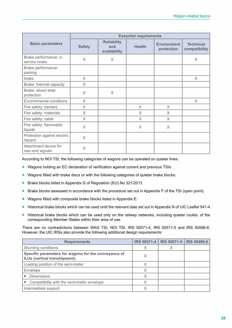
The basic wagon-specific parameters and their correspondence with the essential requirements are set out in Table 1 of WAG TSI:
Basic parameters
Essential requirements
SafetyReliability
and availability
Health Environment protection
Technical compatibility
End coupling XInner coupling XStrength of unit XIntegrity of the unit XGauging X XCompatibility with load carrying capacity of lines X X
Compatibility with train detection system X X
Axle bearing condition monitoring X X
Safety against derailment running on twisted track X X
Running dynamic behaviour X X
Structural design of bogie frame X
Characteristics of the wheelset X X
Characteristics of wheels X XCharacteristics of axles XAxle box/bearings XVariable gauge wheelsets XRunning gear for manual change of wheels X
Brake: safety requirements X X
Brake: general functional requirements X X
29
Wagon-related topics
Basic parameters
Essential requirements
SafetyReliability
and availability
Health Environment protection
Technical compatibility
Brake performance: in service brake X X X
Brake performance: parkingbrake X XBrake: thermal capacity XBrake: wheel slide protection X X
Environmental conditions X XFire safety: barriers X X XFire safety: materials X X XFire safety: cable X X XFire safety: flammable liquids X X X
Protection against electric hazard X
Attachment device for rear-end signals X
According to NOI TSI, the following categories of wagons can be operated on quieter lines:
� Wagons holding an EC declaration of verification against current and previous TSIs.
� Wagons fitted with brake discs or with the following categories of quieter brake blocks:
� Brake blocks listed in Appendix G of Regulation (EU) No 321/2013
� Brake blocks assessed in accordance with the procedure set out in Appendix F of the TSI (open point).
� Wagons fitted with composite brake blocks listed in Appendix E:
� Historical brake blocks which can be used until the relevant date set out in Appendix N of UIC Leaflet 541-4
� Historical brake blocks which can be used only on the railway networks, including quieter routes, of the corresponding Member States within their area of use.
There are no contradictions between WAG TSI, NOI TSI, IRS 50571-4, IRS 50571-5 and IRS 50596-6. However, the UIC IRSs also provide the following additional design requirements:
Requirements IRS 50571-4 IRS 50571-5 IRS 50596-6Shunting conditions X XSpecific parameters for wagons for the conveyance of ILUs (vertical transhipment) X
Loading position of the semi-trailer XEnvelope X � Dimensions X � Compatibility with the semi-trailer envelope X
Intermediate support X

30
Comparative analysis of the combined transport usages and standards (CACTUS) - Final Report
Requirements IRS 50571-4 IRS 50571-5 IRS 50596-6Seating device X � Position X � Dimensions X � Height X � Compatibility with the semi-trailer king pin X � Compatibility with the semi-trailer steering wedge X � Locking X � Visibility of the locking state during the conveyance of
semi-trailers X
Bearing plates X � Position X � Dimensions X
Specific parameters for wagons for the conveyance of swap bodies and ISO containers (vertical transhipment) X
Spigots X � Types X � Shape, dimensions and positioning X � Tests X
Supports for the load transfer areas of swap bodies and containers X
Specific parameters for wagons for the conveyance of roller units X
Pivoting frames XSystems for securing and blocking roller units X � Locking system X � Stoppers X
Tests X � Test requirements for wagons and for intermediary
underframes with pivoting frames X
� Supplementary impact tests for pivoting frames and pivoting frames on intermediary underframes X
� Static tests for pivoting frames and pivoting frames on intermediary underframes X
Parameters linked to the WCC allocation XHeight of the loading plane XBogie wagons: distance between the pivots X2-axle wagons: wagon wheelbase XBogie wheelbase XOverhang XSide bearers X � Side bearers play (j) X � Half-distance between side bearers (bG) X
Total lateral play (q+w) XVehicle flexibility coefficient (s) X

31
Wagon-related topics
Requirements IRS 50571-4 IRS 50571-5 IRS 50596-6Dissymmetry XHeight of the roll centre XTolerances (centring) X � Tolerances to the right of the tyres X � Tolerances to the right of the king pin X � Tolerances to the right of the spigots X
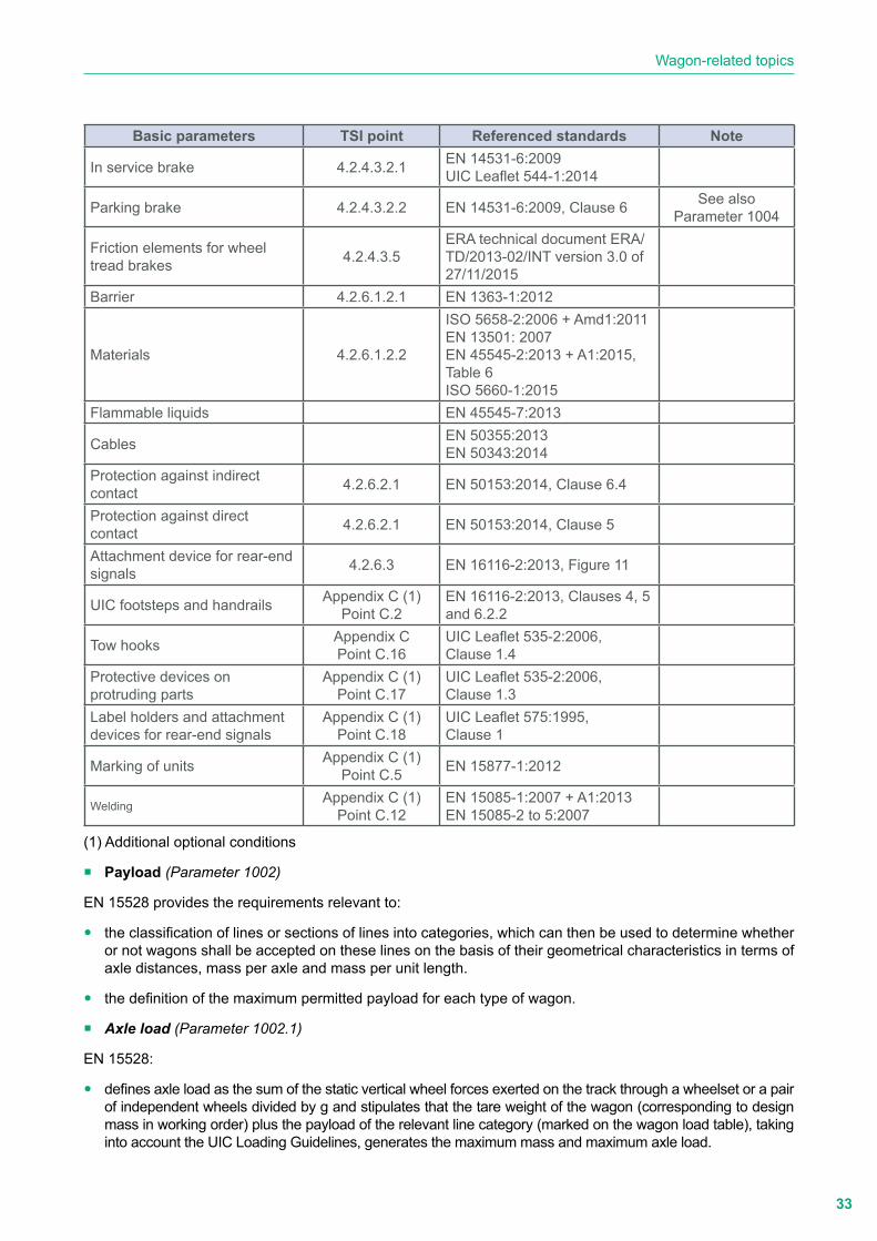
� Interoperability essential requirements and functional and technical specifications (Parameter 1001)
Considering the essential requirements and basic parameters, Chapter 4.2 of WAG TSI provides the functional and technical specifications on:
y structures and mechanical parts (Point 4.2.2);
y gauging and vehicle track interaction (Point 4.2.3);
y brakes (Point 4.2.4);
y environmental conditions (Point 4.2.5); and
y system protection (Point 4.2.6).
Chapter 4.3 provides the functional and technical specifications of the interfaces with:
y the infrastructure subsystem (Table 5);
y the operational and traffic management subsystem (Table 6); and
y the command and signalling subsystem (Table 7).
Appendix C provides additional optional conditions.
For each basic parameter requirement and additional optional condition, the following table shows the technical document to which WAG TSI points refer:
Basic parameters TSI point Referenced standards NoteEnd coupling 4.2.2.1.1
No referenceSee also
Parameters 1006 and 1007Inner coupling 4.2.2.1.2
Manual coupling system Appendix C (1) Point C.1
EN 15551:2009 + A1:2010 EN 15566:2009 + A1:2010(except Clause 4.4)EN 15887-1:2012, Figure 75EN 16116-2:2013,Clause 6.3.2
See also Parameters 1006
and 1007
Strength of unit 4.2.2.2
EN 12663-1:2010 + A1:2014,Clause 9.2EN 12663-2:2010, Clauses 5,6 and 7EN 15877-1:2012, Clauses 4,5 and 14
Integrity of the unit 4.2.2.3 No reference
Ability to be humped and shunted
Appendix C (1) Point C.3
EN 12663-2:2010, Clauses 5and 8
See also Parameter 1005

32
Comparative analysis of the combined transport usages and standards (CACTUS) - Final Report
Basic parameters TSI point Referenced standards Note
Gauging 4.2.3.1 EN 15273-2:2013 See also Parameter 300
Compatibility with load carrying capacity of lines 4.2.3.2 EN 15528:2015, Clauses 6.1
and 6.2See also
Parameter 1002.1Compatibility with train detection system 4.2.3.3 ERA/ERTMS/033281 rev. 4.0
Axle bearing condition monitoring 4.2.3.4 EN 15437-1:2009,
Clauses 5.1 and 5.2Safety against derailment running on twisted track 4.2.3.5.1 EN 14363: 2014, Clauses 4,
5 and 6.1Test concerning long compressive forces
Appendix C (1) Point C.8 EN 15839:2012 + A1:2015
Running dynamic behaviour 4.2.3.5.2
EN 14363: 2016, Clauses 4,5 and 7EN 16235:2013EN 13749:2011, Clause 6.2
Structural design of bogie frame 4.2.3.5.3 EN 13749:2011, Clause 6.2
Characteristics of the wheelset 4.2.3.6.2 EN 13260:2009 + A1:2010,Clause 3.2.1
Characteristics of wheels 4.2.3.6.3 EN 13979-1:2003 + A1:2009 +A2:2011, Clauses 7 and 6.2
Specific product properties concerning the wheels
Appendix C (1) Point C.15
EN 12362:2004EN 13979-1:2003
Characteristics of axles 4.2.3.6.4 EN 13103:2009 + A2:2012,Clauses 4, 5, 6 and 7
Axle box/bearings 4.2.3.6.5 EN 12082:2007 + A1:2010,Clause 6
Variable gauge wheelsets 4.2.3.6.5 No reference
Running gear for manual change of wheels 4.2.3.6.7
UIC Leaflet 430-1:2012,Appendices B, H and I UIC Leaflet 430-3:1995,Appendix 7
Brake: safety requirements 4.2.4.2 Reference for UIC brake toAppendix C, Point C.9
See alsoParameter 1004
Brake: general functional requirements 4.2.4.3.1 ISO 5658-2:2006 + Am1:2011
EN 13501-1:2007 + A1:2009
UIC brake Appendix C (1) Point C.9
EN 15355:2008 + A1:2010 EN 15611:2008 + A1:2010 EN 14531-1:2015EN 15624:2008 + A1:2010 EN 15625:2008 + A1:2010 EN 286-3:1994EN 286-4:1994EN 15807:2011EN 14601:2005 + A1:2010 EN 15595:2009 + A1:2011UIC Leaflet 540:2014UIC Leaflet 541-1:2014UIC Leaflet 541-4:2010UIC Leaflet 542:2015
33
Wagon-related topics
Basic parameters TSI point Referenced standards Note
In service brake 4.2.4.3.2.1 EN 14531-6:2009UIC Leaflet 544-1:2014
Parking brake 4.2.4.3.2.2 EN 14531-6:2009, Clause 6 See alsoParameter 1004
Friction elements for wheel tread brakes 4.2.4.3.5
ERA technical document ERA/TD/2013-02/INT version 3.0 of 27/11/2015
Barrier 4.2.6.1.2.1 EN 1363-1:2012
Materials 4.2.6.1.2.2
ISO 5658-2:2006 + Amd1:2011 EN 13501: 2007EN 45545-2:2013 + A1:2015,Table 6ISO 5660-1:2015
Flammable liquids EN 45545-7:2013
Cables EN 50355:2013EN 50343:2014
Protection against indirect contact 4.2.6.2.1 EN 50153:2014, Clause 6.4
Protection against direct contact 4.2.6.2.1 EN 50153:2014, Clause 5
Attachment device for rear-end signals 4.2.6.3 EN 16116-2:2013, Figure 11
UIC footsteps and handrails Appendix C (1) Point C.2
EN 16116-2:2013, Clauses 4, 5and 6.2.2
Tow hooks Appendix CPoint C.16
UIC Leaflet 535-2:2006,Clause 1.4
Protective devices on protruding parts
Appendix C (1) Point C.17
UIC Leaflet 535-2:2006,Clause 1.3
Label holders and attachment devices for rear-end signals
Appendix C (1) Point C.18
UIC Leaflet 575:1995,Clause 1
Marking of units Appendix C (1) Point C.5 EN 15877-1:2012
Welding Appendix C (1) Point C.12
EN 15085-1:2007 + A1:2013EN 15085-2 to 5:2007
(1) Additional optional conditions
� Payload (Parameter 1002)
EN 15528 provides the requirements relevant to:
y the classification of lines or sections of lines into categories, which can then be used to determine whether or not wagons shall be accepted on these lines on the basis of their geometrical characteristics in terms of axle distances, mass per axle and mass per unit length.
y the definition of the maximum permitted payload for each type of wagon.
� Axle load (Parameter 1002.1)
EN 15528:
y defines axle load as the sum of the static vertical wheel forces exerted on the track through a wheelset or a pair of independent wheels divided by g and stipulates that the tare weight of the wagon (corresponding to design mass in working order) plus the payload of the relevant line category (marked on the wagon load table), taking into account the UIC Loading Guidelines, generates the maximum mass and maximum axle load.
34
Comparative analysis of the combined transport usages and standards (CACTUS) - Final Report
y provides the tolerances for the categorisation of the wagons into line categories and requires that the payloads of the load table shall be revised if changes in axle load of more than 100 kg, whether because of technical alterations or as a change of the axle load distribution, occur.
The compatibility of wagons and their loads with the load capacity of lines is determined by their geometrical and load characteristics, i.e. axle spacing, axle loads and the resulting mass per unit length.
Annexes G, H and I provide the methodology for calculating the maximum permissible payload and axle load for each type of wagon corresponding to each line category.
The above payload limits are only valid if the permissible payload is evenly distributed over the length of the wagon. In the case of longitudinally displaced or unevenly distributed loading, the payload shall be reduced, so that the value of the permissible axle load is not exceeded.
As an exception, 20 t axle loads may be exceeded by up to 0.5 t on Category C lines for:
y 2-axle wagons with 20 t axle loads and 14.10 m < length over buffers < 15.50 m to bring their payload up to 25 t.
y wagons designed for 22.5 t axle loads to offset the extra tare incurred in making them suitable for such axle loads.
The maximum permissible wheel load shall be 11.1 t.
EN 15528 does not provide a methodology for calculating axle load limits and the payload when the wagon load is unevenly distributed or articulated wagons are concerned (i.e. articulated wagons equipped with three 2-axle bogies).
The number of articulated wagons represents a significant proportion of the CT wagon fleet. Due to the maximum gross weight (MGW), ILU length and their combinations when they are loaded on the wagons, the distribution of the wagon load is never uniform.
� Minimum axle load (Parameter 1002.2)
The minimum axle load corresponds to the value measured when the wagon is empty.
Axle load activates pedals and treadles and has also a beneficiary effect on the resistance between wheel and track, which is important for the operation of track circuits. Friction elements acting on wheel surfaces help to keep them clean and limit the increase of contact resistance.
ERA/ERTMS/033281 rev. 04 provides the following vehicle axle load harmonised parameters for 1,435 mm, 1,524 mm, 1,600 mm and 1,668 mm track gauges:
y at least 3.5 t for wagons with more than 4 axles and wheel tread brakes;
y at least 4 t for wagons with 4 axles and wheel tread brakes; and
y at least 5 t for wagons that do not fall into the above-mentioned categories (i.e. disc brakes).
In all cases, the minimum axle load of a wagon depends on the tare of the type that has been successfully submitted to the strength, dynamic and derailment tests on twisted tracks according to the technical documents referenced in WAG TSI.
� Structural requirements of wagon bodies (Parameter 1003)
In accordance with IRS 50571-4 (Point 1) and IRS 50571-5 (Point 1).
y CT wagons shall comply with the version of WAG TSI in force at the time the order to develop/build the wagons was made.
y In deviation from UIC Leaflet 530-1, Point 2.1.1, CT wagons may be built to withstand pressure stresses of:

35
Wagon-related topics
• 1,200 kN along the wagon centreline, and
• 600 kN on each buffer, along the buffer centreline, in accordance with EN 12663-2.
y It shall be possible for loaded wagons to be lifted at the designated points, as specified by EN 15877-1.
� Braking equipment (Parameter 1004)
In addition to the mandatory requirements provided by WAG TSI, NOI TSI and the referenced technical documents, the following requirements apply:
y IRS 50571-4, Point 1.6 and IRS 50571-5, Point 2.2.1: CT wagons shall be equipped with a self- adjusting load-proportional brake.
y IRS 50571-5, Point 2.2.1: wagons suitable for the conveyance of roller units shall be equipped with a parking brake that can be operated from the ground.
� Shunting conditions (Parameter 1005)
In accordance with IRS 50571-4, Point 1.7, in order to avoid damage to ILUs and/or their load, care shall be taken when shunting loaded wagons.
The wagons shall not buff other wagons unbraked and must be protected against being buffed by other unbraked wagons. During operation, the maximum buffing speed must not exceed 6 km/h (empty wagons are not subject to this restriction). If a loaded wagon must be protected from bumping, a dedicated marking shall be affixed to the CT wagons.
� Buffer and coupling (Parameter 1006)
In addition to the mandatory requirements provided by WAG TSI and the referenced technical documents, the following requirements are provided by IRS 50571-5 and UIC Leaflet 572.
UIC Leaflet 572 applies to the inner coupling of multiple wagons (permanently coupled).
In accordance with IRS 50571-5, Point 2.2, carrier wagons suitable for the carriage of roller units shall be fitted with buffers or shock absorbers that ensure that the acceleration on the pivoting frame does not exceed 4 g during impact at speeds of 12 km/h. If this requirement is not met, these wagons may not be hump-shunted and shall be marked with a pictogram as per EN 15877-1, Figure 54a.
� Digital Automatic Coupling (Parameter 1007)
No requirements are provided in WAG TSI, IRS 50571-4 and IRS 50571-5 on Digital Automatic Coupling.
� Conveyance of wagons on ferries (Parameter 1008)
In accordance with IRS 50571-4 (Point 1.9) and IRS 50571-5 (Point 1.6), CT wagons shall be able to run over a maximum break angle of 1° 30' on a 120 m-radius curve on ferry lines.
� Specific parameters for wagons for the conveyance of semi-trailers (vertical transhipment) (Parameter 1100)
In addition to the requirements provided by WAG TSI, the referenced technical documents, IRS 50571-4 and IRS 50596-5, provide requirements on the following parameters related to CT wagons suitable for the conveyance of semi-trailers:
y Loading position of the semi-trailer
y Semi-trailer envelope
y Intermediate supports
y Seating device
y Bearing plates

36
Comparative analysis of the combined transport usages and standards (CACTUS) - Final Report
� Loading position of the semi-trailer (Parameter 1101)
IRS 50571-4 provides requirements on two types of pocket wagons designed for the conveyance of semi-trailers:
y Pocket wagons with wagon compatibility code P and equipped with a loading recess and a seating device
y Pocket wagons with wagon compatibility code N and equipped with a loading recess and bearing plates fitted with UIC-compliant spigots
Once loaded on a pocket wagon with wagon compatibility code P, the semi-trailer stands with its wheels placed in the loading recess (fixed pocket) and its fifth wheel positioned on the seating device. It is secured lengthwise by its king pin, blocked by the seating device and wheel scotches if necessary.
Semi-trailers loaded on wagons with wagon compatibility code N stand with their wheels placed in the loading recess and the front part positioned on the bearing plates. They are secured crosswise in the wagon using the spigots and lengthwise by the wheel scotches in the recess.
� Wagon envelope (Parameter 1102)
The term ‘wagon envelope’ identifies the lower space provided in the pocket wagon for the placement of the semi-trailer wheels. For the design of the wagon envelope, IRS 50571-4, Point 3.3.1.1 refers to IRS 50596-5 (Appendices F.1 to F.9).
� Dimensions (Parameter 1102.1)
IRS 50596-5, Appendices F.1 to F.9 provide, for each type of semi-trailer identified by its wagon compatibility code:
y the dimensions of the lower part of the semi-trailer envelope which must be taken into account for the design of the envelope of the compatible pocket wagon.
y the values of the loading plane height and the distance between the pivot of the bogies (if this last value is modified, the requirements provided in IRS 50596-6 shall be considered).
IRS 50596-6 provides the value of the centring tolerances (clearances) between the wheels of the semi-trailer and the pocket.
� Compatibility with the semi-trailer envelope (Parameter 1102.2)
The envelope compatibility code identifies the compatibility between the pocket wagon and one or more types of semi-trailers. The list of envelope compatibility codes is provided in IRS 50596-5.
In accordance with IRS 50571-4, each type of pocket wagon shall be assigned one or more envelope compatibility codes depending on its characteristics.
Envelope compatibility codes are assigned by UIC SET 03 following the examination of a technical file submitted by an applicant. The relevant envelope is published as an appendix to IRS 50596-5.
� Intermediate support (Parameter 1103)
In accordance with Point 2.3, pocket wagons shall be equipped with intermediate supports for the conveyance of ILUs (length groups: 40 to 53 and 91 to 98) to limit vertical vibrations and avoid excessive stresses on the ILU structure.
In accordance with Point 3.3.1.5, where pocket wagons are fitted with intermediate supports for swap bodies, each intermediate support must be able to absorb a force of 75 kN in the vertical direction.
Intermediate supports must be positioned to meet the requirements provided in IRS 50592 for ILUs other than semi-trailers.

37
Wagon-related topics
� Seating device (Parameter 1104)
The term ‘seating device’ (‘hitch’ in some documents) identifies the equipment that supports the front part of the semi-trailer when it is loaded onto a pocket wagon.
To prevent the semi-trailer from flying away due to the aerodynamic effects occurring during transport, the seating device is provided with a dedicated tool that locks the king pin.
IRS 50571-4 provides requirements on:
y the dimensions, position and height in relation to height of the loading plane of the seating device;
y the compatibility of the seating device with the semi-trailer king pin and steering wedge;
y the locking of the king pin by the dedicated tool provided in the seating device; and
y he visibility of the state of the locking during the conveyance of semi-trailers.
� Position (Parameter 1104.1)
Pocket wagons can be equipped with:
y an adjustable seating device which can move longitudinally to meet the position of the king pin of the semi-trailer when its wheels are positioned in the recess and secured by the scotches; or
y a non-adjustable seating device which is fastened to the wagon frame and secures the semi- trailer during rail transport.
The range within which the longitudinal positioning of the seating device is possible is shown in IRS 50596-5, Appendices F.1 (compatibility code a), F.4 (compatibility code d), F.8 (compatibility code h) and F.9 (compatibility code i).
IRS 50596-5, Appendices F.5 (compatibility code e), F.6 (compatibility code f) and F.7 (compatibility code g) provide the position of the non-adjustable seating device in relation to the bogie pivot.
� Height (Parameter 1104.2)
The value of this parameter corresponds to the height of the supporting plane of the seating device in relation to the level of the loading plane of the recess (pocket). It depends on the types of semi- trailer which can be conveyed on the pocket wagon.
Recent types of pocket wagons are fitted with height adjustable seating devices allowing two or three height levels.
IRS 50596-5, Appendices F.1 to F.9 provide the values of the height of the seating devices in relation to the compatibility code of the wagons.
Appendix F.1: Height of the seating device = 1,130/980 mm (compatibility code a)
Appendix F.4: Height of the seating device = 1,130/980/850 mm (compatibility code d)
Appendix F.5: Height of the seating device = 1,130/980/880 mm (compatibility code e)
Appendix F.6: Height of the seating device = 1,130/980/850 mm (compatibility code f)
Appendix F.7: Height of the seating device = 1,130/980/850 mm (compatibility code g)
Appendix F.8: Height of the seating device = 1,130/980/850 mm (compatibility code h)
Appendix F.9: Height of the seating device = 1,130/980/850 mm (compatibility code i)

38
Comparative analysis of the combined transport usages and standards (CACTUS) - Final Report
� Width (Parameter 1104.3)
In accordance with IRS 50571- 4, Point 3.4.6, the seating device width must comply with the requirements provided in Regulation (EC) No 661/2009.
� Compatibility with the semi-trailer king pin (Parameter 1104.4)
In accordance with IRS 50571-4, Point 3.4.2, the seating device is to be configured to be coupled with H-type 2" king pins complying with Regulation (EC) No 661/2009.
NB Regulation (EC) No 661/2009 amended and supplemented by Regulation (EU) 166/2015 requires the mandatory application of UNECE Regulation No. 55 to mechanical coupling components of road vehicles of categories N and O.In accordance with UNECE Regulation No. 55 (paragraph 8.1), the dimensions of the king pin shall be compliant with ISO 337 requirements.
� Compatibility with the semi-trailer steering wedge (Parameter 1104.5)
In accordance with IRS 50571-4:
y Point 3.4.4: The dimensions of the seating device shall meet the criteria for steering wedges laid down by Regulation (EC) No 661/2009 (this requirement only applies to new semi- trailers).
y Point 3.4.5. If the seating device is not suitable for semi-trailers with steering wedges, the wagon is to be marked with a specific pictogram.
� Locking device (Parameter 1104.6)
In accordance with IRS 50571-4, Point 3.4.2, the seating device must be fitted with a simple device which locks the fifth king pin automatically in the slot and can be unlocked manually from either side.
� Visibility of the locking state during the conveyance of semi-trailers (Parameter 1104.7)
IRS 50571-4, Point 3.4.3 provides requirements to be fulfilled by the locking device to let train inspectors:
y confirm, from a standing position at ground level from either side of the wagon, that the king pin is correctly locked in the seating device; and
y relock the king pin without having to lift the semi-trailer again.
� Bearing plates (Parameter 1105)
Pocket wagons with wagon compatibility code N may be provided, in addition to the restraint devices used for the conveyance of swap bodies and ISO containers, with specific bearing plates fitted with spigots complying with the requirements provided by IRS 50571-4.
� Dimensions (Parameter 1105.1)
The dimensions of the bearing plates shall be compatible with those of the supporting shoes of the semi-trailer as provided in IRS 50596-5, Appendices C and D.
� Location (Parameter 1105.2)
The location of the bearing plates to be used when semi-trailers are conveyed is provided by IRS 50596-5, Appendix C.
� Specific parameters for wagons for the conveyance of swap bodies and ISO containers(Parameter 1200)
In addition to the requirements provided by WAG TSI and the referenced technical documents, IRS 50571-4 and IRS 50592 provide requirements for the following parameters of CT wagons suitable for the conveyance of swap bodies (wagon compatibility code C) and ISO containers (wagon compatibility code ISO):
39
Wagon-related topics
y Spigots
y Supports for the load transfer areas of containers and swap bodies
� Spigots (Parameter 1201)
In accordance with IRS 50571-4, Point 2.4, CT wagons shall be equipped with restraining devices to secure containers and swap bodies through their lower corner fittings.
� Types (Parameter 1201.1)
In accordance with IRS 50571-4, Point 2.4, CT wagons may be equipped with fixed, fold-away, retractable, adjustable devices to secure containers and swap bodies through their lower corner fittings. Other solutions are permitted if these offer equivalent effectiveness.
� Shape, dimensions and positioning (Parameter 1201.2)
IRS 50571-4, Appendix B.1 provides the manufacturing dimensions and tolerances of the spigots.
IRS 50571-4, Appendix B.2 provides the limit values of the functional dimensions of the cross- distance between spigots and the limit values for the spigots themselves.
IRS 50571-4, Appendix B.3 provides an assembly diagram for fold-down spigots complying with the limit values provided in Appendix B.2.
� Strength (Parameter 1201.3)
In accordance with IRS 50571-4, Point 2.3, if the restraining devices are fitted with spigots for securing ILUs, the material from which the spigot is made shall, as a minimum, meet the strength requirements for materials in EN 10293, category GE270. By extension, this also applies to the means by which the restraining devices are fixed to the wagon (welding, screw, form fit, etc.), which transmit the forces to the wagon structure.
In accordance with IRS 50592, Point 5.1, CT wagons designed for the conveyance of heavy-duty ILUs (MGM > 36,000 kg) shall be equipped with reinforced restraining devices (to be tested under maximum ILU mass against EN 12663-2).
� Tests (Parameter 1201.4)
In accordance with:
y IRS 50571-4, Point 2.3, the test requirements on CT wagon restraining devices are defined in EN 12663-2.
y IRS 50592, Point 5.1, the reinforced restraining devices fitted to CT wagons designed for the conveyance of heavy-duty ILUs shall be tested under maximum ILU mass against EN 12663-2.
� Supports for the load transfer areas of containers and swap bodies (Parameter 1202)
As ILUs other than semi-trailers are fitted with load transfer areas in their base structure allowing load transfer to the longitudinal members of carrying vehicles (road and rail), CT wagons shall be equipped with supports which are able to limit vertical vibrations exceeding the permissible limit of the ILU structure (IRS 50571-4, Point 2.3).
� Specific parameters for wagons for the conveyance of roller units (vertical transhipment)(Parameter 1300)
In addition to the requirements provided by WAG TSI and the referenced technical documents, IRS 50571-4 and IRS 50591 provide requirements for the following parameters of CT wagons suitable for the conveyance of roller units:
y Pivoting frames
y Systems for securing and blocking the roller units
y Tests
40
Comparative analysis of the combined transport usages and standards (CACTUS) - Final Report
� Pivoting frames (Parameter 1301)
The following mandatory requirements on pivoting frames are provided in IRS 50571-5, Point 2.3:
y Pivoting frames may either be an inseparable part of the wagon underframe or be secured by means of an intermediary underframe fixed to the container wagon, as per IRS 50571-4.
y Pivoting frames and intermediary underframes shall be able to withstand the forces exerted during operation.
y Pivoting frames shall be designed to receive compatible roller units as defined in IRS 50591; the characteristics of the pivoting frames for each roller unit type are set out in Appendices A.2, A.3 and A.4.
y It shall be possible for the frame to pivot on both sides, and it shall be possible to move the pivoting frame inwards and outwards from the road vehicle using, for example, a sling.
� Systems for securing and blocking roller units (Parameter 1302)
IRS 50571- 5 provides requirements on the locking system and stoppers.
� Locking system (Parameter 1302.1)
Point 2.4.1 provides the following requirements on the system fitted to the wagons to secure and block roller units:
y The locking system shall be able to withstand the maximum loads occurring during tests and regular service.
y It shall be possible to lock the pivoting frame into the central position (transport position), both in empty and in laden mode.
y Two pivoting-prevention devices, which operate independently of one another, shall be provided for each pivoting frame. At least one of them must be positioned in such a way that it is easily visible and checkable from the outside.
If this pivoting-prevention device is not in the correct position, a pneumatic monitoring system must operate on the brake system to prevent the departure of the train. In order to prevent the system disrupting operations, a shut-off valve shall be provided to isolate the system.
y The locking system shall be able to prevent any uplift or displacement of the roller units when loaded onto the wagon. It shall be possible to combine anti-sliding, anti-uplift and anti-pivoting locking devices.
y It shall be possible to operate the levers for locking the load from track level on the side of the wagon used for loading and unloading.
� Stoppers (Parameter 1302.2)
Stoppers are devices installed on wagons to limit the pivoting angle of the frame. They do not have a locking function.
In accordance with Point 2.4.2, the frame shall be fitted with at least one stopper to maintain it in its central position.
� Tests (Parameter 1303)
IRS 50571-5 provides specific requirements on:
y tests to be performed on wagons suitable for the conveyance of roller units and intermediary underframes with pivoting frames (Point 2.8.3);
y supplementary impact tests for pivoting frames and pivoting frames on intermediary underframes (Point 2.8.4); and
y static tests for pivoting frames and pivoting frames on intermediary underframes (Points 2.5 and 2.8.5).
41
Wagon-related topics
� Test requirements for wagons and intermediary underframes with pivoting frames(Parameter 1303.1)
In accordance with Point 2.8.3.1, the two end roller units on the wagon shall be loaded to the maximum permissible load for their pivoting frames; the roller unit in the middle shall only be loaded to reach the maximum permissible load of the wagon.
y Wagons fitted with Category A buffers shall be impact-tested up to a speed of 7 km/h.
y Wagons fitted with Category L buffers shall be impact-tested up to a speed of 12 km/h.
Before each impact test, the play between the roller units and the stoppers shall be at maximum level.
The stoppers and locking systems which transmit longitudinal forces from the roller unit to the wagon must be evaluated in respect of the stresses and elongations they have sustained. The elastic limit must not be exceeded.
� Supplementary impact tests for pivoting frames and pivoting frames on intermediary underframes (Parameter 1303.2)
Impact tests on a single pivoting frame under maximum load shall be conducted to test the functions of the pivoting frame and to check the strength of the locks when subjected to the maximum accelerations encountered in service for a loaded pivoting frame.
Maximum forces are only exerted on the pivoting frame, its stoppers and locking system when the pivoting frame is loaded to the maximum permissible limit.
The pivoting frame to be tested shall be located on the side of the impact.
� Static tests for pivoting frames and pivoting frames on intermediary underframes(Parameter 1303.3)
To ensure safety against overturning of the wagon during loading and unloading, the maximum number of frames that may be pivoted without compromising safety against overturning shall be defined by means of static tests or calculations.
If static tests are performed, the roller units shall be loaded to 1.4 times the permitted load for the pivoting frame, with the load spread evenly and the frame in fully pivoted position. The non-pivoted frames are to be empty.
� Parameters linked to the WCC allocation (Parameter 1400)
The wagon compatibility code (P, N, C, ISO, B) identifies CT wagons suitable for the transport of the different types of ILUs.
The P or N marking is affixed to pocket wagons complying with the requirements of IRS 50571-4 and suitable for the transport of semi-trailers complying with IRS 50596-5.
The C or ISO marking is affixed to carrier wagons complying with the requirements of IRS 50571-4 and suitable for the transport of ILUs complying with IRS 50592.
The B marking is affixed to carrier wagons complying with the requirements of IRS 50571-5 and suitable for the transport of ILUs complying with IRS 50591.
The values of the parameters to be considered for the allocation of the WCC to CT wagons are provided in IRS 50596-6, Points 1.3, 1.4 and 3.1 (Table 2) and Appendices 4.1 to 4.4.
CT lines are coded based on the characteristics of the reference wagons provided in IRS 50596-6, Point 1.3 (semi-trailer) and Point 1.4 (swap bodies and ISO containers). These characteristics correspond to those of the CT wagon types used in codified combined transport since the beginning.

42
Comparative analysis of the combined transport usages and standards (CACTUS) - Final Report
The evolution of the dimensions and maximum gross mass of ILUs and the requirements of stakeholders have meant that the length of the loading plane of CT wagons has increased and, consequently, new requirements have been introduced to ensure that the change in the longitudinal dimensions of wagons has no impact on compatibility with the CTP of lines.
Appendices A.1 to A.4 provide the criteria for defining the equivalence between the reference wagons and CT wagons with characteristics other than those provided by IRS 50596-6, Points 1.3 and 1.4.
� Height of the loading plane (Parameter 1401)
� Bogie wagons: distance between the pivots (Parameter 1402)
� 2-axle wagons: wagon wheelbase (Parameter 1403)
� Overhang (Parameter 1404)
Appendix A.1 provides the equivalence curve (height of the loading plane vs. distance between bogie pivots) for bogie wagons suitable for the conveyance of swap bodies and roller units.
Depending on the distance between the bogie pivots, the height of the loading plane in relation to the rail level decreases:
y from 1,175 mm to 1,100 mm (wagons suitable for the conveyance of swap bodies); and
y from 1,400 mm to 1,325 mm (wagons suitable for the conveyance of roller units). The maximum permitted value for the distance between the pivot bogies is 16,150 mm.
Appendix A.3 provides the equivalence curve for bogie wagons suitable for the conveyance of semi- trailers.
Depending on the distance between the bogie pivots, the height of the loading plane in relation to the rail level decreases from 330 mm to 270 mm.
The height of the plane of the seating device in relation to the height of the loading plane depends on the compatibility code of the semi-trailer (see also Parameter 1104).
The maximum permitted value for the distance between the pivot bogies is 14,200 mm.
Appendix A.4 provides the equivalence curve (height of the loading plane vs. distance between bogie pivots) for bogie wagons suitable for the conveyance of ISO containers.
Depending on the distance between the bogie pivots, the height of the loading plane in relation to the rail level decreases from 1,175 mm to 1,010 mm.
The maximum permitted value for the distance between the pivot bogies is 19,300 mm.
The maximum value of the overhang in relation to the bogie pivot shall be such as to allow the fulfilment of the following requirement:
Ei > Ea
Where:
y Ei is the reduction value for the reference profile half-width dimensions for the sections located between the end axles of vehicles not mounted on bogies or between the pivots of vehicles mounted on bogies.
y Ea is the reduction value for the reference profile half-width dimensions for the sections beyond the end axles of vehicles not mounted on bogies or the pivots of vehicles mounted on bogies.
Appendix A.2 provides the equivalence curve (height of the loading plane vs. overhang) for 2-axle wagons suitable for the conveyance of swap bodies and roller units. It applies to 2-axle wagons with a wheelbase of 8,000 mm, 9,000 mm or 10,000 mm.

43
Wagon-related topics
Depending on the overhang in relation to the axles, the height of the loading plane in relation to the rail level decreases:
y from 1,175 mm to 1,155 mm (wagons suitable for the conveyance of swap bodies); and
y from 1,400 mm to 1,380 mm (wagons suitable for the conveyance of roller units).
The following table provides the maximum permitted value for the overhang as a function of the CT wagon wheelbase.
Wheelbase Max. overhang8,000 mm 2,270 mm9,000 mm 2,550 mm10,000 mm 2,550 mm
� Bogie wheelbase (Parameter 1405)
See Table A below.
� Side bearers (Parameter 1406)
The interface of the wagon underframe with the bogie of the wagon consists of a pivot bearer and two spring side bearers. The coupling between the bogie and the wagon underframe is made by means of the central pin.
The interface allows the pivoting and rotation of the bogie and the pivot bearing, and the spring side bearers provide the wagon with the rotational torque it needs to have an acceptable dynamic behaviour.
� Side bearers play (j) (Parameter 1406.1)
The value of this parameter corresponds to that of the vertical displacement of the side bearer supporting plate (see Table A below).
� Half-distance between side bearers (bG) (Parameter 1406.2)
The value of this parameter corresponds to that of the distance between the side bearer and the pivoting centre (see Table A below).
� Total lateral play (q+w) (Parameter 1407)
The total lateral play of the CT wagon (q+w) corresponds to the sum of the transverse clearance q between wheelset and bogie frame or between wheelset and body for wagons not fitted with bogies and of the transverse clearance w between the bogie frame and the body (see Table A below).
� Vehicle flexibility coefficient (s) (Parameter 1408)
Whenever a stationary wagon loaded with a compatible ILU is placed on a canted track whose running surface lies at an angle δ to the horizontal, its body leans on its suspension and forms an angle η with the perpendicular to the rail level. The vehicle flexibility coefficient s is defined by the ratio:
s = η/ δ
See Table A below.
� Dissymmetry (η0) (Parameter 1409)
The value of this parameter corresponds to the angle η0 that would be made by the centreline of the body of a stationary vehicle on a level track relative to the vertical in the absence of any friction (see Table A below).
� Height of the roll centre (Parameter 1410)
The value of this parameter corresponds to the height of the roll centre of the ILU + CT wagon (see Table A below).

44
Comparative analysis of the combined transport usages and standards (CACTUS) - Final Report
� Tolerances (centring) (Parameter 1411)
The tolerances to be considered during the coding process according to IRS 50596-6 are the subject of Parameters 1411.1 to 1411.3.
� Tolerances to the right of the tyres (Parameter 1411.1)
� Tolerances to the right of the king pin (Parameter 1411.2)
� Tolerances to the right of the spigots (Parameter 1411.3)
Table A provides the values of the maximum offset of ILUs as a result of centring tolerances near the wheels, near the seating or bearing devices for semi-trailers, containers, swap bodies and roller units.
Parameter
Bogie wagons 2-axle wagons
Semi- trailers
Swap bodies &
containers
Roller units
Swap bodies &
containers
Roller units
Bogie wheelbase 2,000 mm 2,000 mm 2,000 mmSide bearer � Play (j) 12 (+2/0) mm (a) � Half-distance (bG) 850 mm
Total lateral play (q+w) 11.5 11.5 11.5 11.5 11.5Wagon flexibility (s) 0.30 0.15 0.15 0.15 0.15Height of the roll centre (HC) � Semi-trailers + pocket wagons 1,000 mm � Swap bodies, ISO containers, roller
units + CT wagons 500 mm 500 mm 500 mm 500 mm
Tolerances (centring) � Tolerances to the right of the tyres 10 mm � Tolerances to the right of the king
pin 10 mm
� Tolerances to the right of the spigots 10 mm 10 mm 10 mm 10 mm
� Lateral play between the roller unit and the pivoting frame 20 mm 20 mm
(a) For new and modified wagons, the value of 9 (+1/0) mm is admitted
Table A: Characteristics of CT wagons
� Identification and markings (Parameter 300)
Requirements on wagon identification and markings are provided by WAG TSI, OPE TSI, IRS 50571-4, IRS 50571-5, IRS 50596-6 and the GCU, Appendix 11.
� Identification (Parameter 300.1)
In accordance with OPE TSI, Point 4.2.2.3 and Appendix H, wagons are identified by a marking consisting of:
y the European Vehicle Number (EVN) assigned as defined in Appendix 6 of Annex II to the Commission Implementing Decision (EU) 2018/1614;
y the acronym of the registering country; and
y the acronym of the wagon keeper.
45
Wagon-related topics
It shall also be possible to identify operational restrictions applicable to the wagons.
TEN marking is assigned to wagons which are provided with an authorisation valid for an area of use covering all European Member States.
PPV/PPW marking is assigned to wagons which are provided with PPV/PPW or PGW agreement (inside OSJD countries).
Wagons which are provided with an authorisation valid for an area of use which does not cover all European Member States need a marking indicating the Member States which are part of the area of use of the vehicle. Examples of this marking are provided in OPE TSI, Appendix H, Point 6.
CT wagons with more favourable or less favourable characteristics than the reference wagon are identified by a marking providing the corresponding correction digit for each Member State.
� Operational markings (Parameter 300.2)
In accordance with WAG TSI, Chapter 7, wagons shall be marked with all applicable markings in accordance with EN 15877-1:2012, in particular with markings on the following:
y The allocated interoperable gauge
y The vehicle tare weight
y The vehicle load table
y The length over buffers
y Maintenance dates
y Lifting and re-railing signs
y The distance between the two end axles of the unit
y The distance between bogie centres
y The brake weight
y The track gauge(s) the unit is compatible with and was assessed for
Concerning CT wagons, EN 15877- 1 provides the following markings:
y WCC for wagons suitable for the conveyance of swap bodies (Figure 84)
y WCC and correction digits for wagons suitable for the conveyance of swap bodies, with more favourable or less favourable characteristics than the reference wagon (Figure 85)
y WCC for wagons suitable for the conveyance of P coded semi-trailers (Figure 86)
y WCC and correction digits for wagons suitable for the conveyance of semi-trailers, with more favourable or less favourable characteristics than the reference wagon (Figures 87a and 87b)
y WCC for wagons suitable for the conveyance of N coded semi-trailers (Figure 90)
y WCC for wagons suitable for the conveyance of roller units (Figure 88)
CT wagons bearing a marking complying with Figures 85, 87 or 89 (left-hand image of EN 15877-1) shall be fitted in addition with a derogation plate complying with Figure 77 of EN 15877-1.
IRS 50571-4 refers to EN 15877-1 and in addition provides requirements on the mandatory marking of CT wagons with:
y numbers for identifying the position of the spigots;

46
Comparative analysis of the combined transport usages and standards (CACTUS) - Final Report
y the loading diagram, including the spigot positions and their length dimensions relative to the centre of the bogie and the spigot position number (Appendix A, Figure 1);
y an additional loading diagram for wagons fitted with reinforced spigots for the conveyance of heavy-duty containers in accordance with IRS 50592 (Appendix E.1, Figure 11);
y the pictogram “Heavy duty” for wagons designed for the conveyance of heavy-duty containers in accordance with IRS 50592 (Appendix E.2, Figure 12);
y the pictogram “Fly and hump-shunting of loaded wagons not permitted” (Appendix F, Figure 13);
y the pictogram for seating devices unsuitable for use with steering wedges (Appendix C, Figure 8); and
y the pictogram showing the last four digits of the wagon number to be allocated on the upper surface of the outer solebars of the solebar to help crane operators identify the wagon (Appendix D, Figure 9).
IRS 50571-5 refers to EN 15877-1 and in addition provides requirements on the mandatory marking of wagons suitable for the conveyance of roller units with:
y warning “Not to be moved with frame in pivoted position” (Appendix A.6, Figures 1 and 2);
y pictogram showing the “Procedure for loading and unloading” (Appendix A.6, Figure 3);
y pictogram for “Maximum permitted number of frames that may be pivoted without compromising safety against overturning” (Appendix B.1);
y pictogram for “Pivoting frame overhang” (Appendix B.2); and
y pictogram for “Locking lever during transport” (Appendix B.3).
The GCU Appendix describes the inscriptions and signs to be affixed to wagons and indicates where they should be positioned.
As this document is intended for RU operational staff, the inscriptions and signs have been grouped together according to certain processes or operations: the loading and provision of wagons, combined transport, train preparation, shunting, technical inspections, workshops, and key warning signs.
� Maintenance (Parameter 400)
In accordance with Directive (EU) 2016/798 (Safety directive) each wagon, before being used on the network, shall be assigned an Entity in Charge of Maintenance (ECM).
The ECM shall be certified in accordance with Regulation (EU) 445/2011 and registered as such in the vehicle register.
The ECM is responsible for establishing a maintenance system for the wagons and, by means of that system, it shall ensure that wagons are maintained in accordance with the relevant maintenance file and the requirements in force, including maintenance rules and relevant TSI provisions.
The keeper shall provide the ECM with the full maintenance file that is part of the technical file submitted to the ERA or to a National Safety Authority (NSA) when the application for marketing authorisation for the type of wagon is made.
In accordance with WAG TSI, Point 4.5, the maintenance file shall consist of:
y the general documentation (Point 4.5.1);
y the maintenance design justification file (Point 4.5.2); and
y the maintenance description file (Point 4.5.3).
This documentation may be modified later by the ECM in accordance with the corresponding EU legislation, considering the existing operating and maintenance conditions of the wagon.
47
Wagon-related topics
The general documentation consists of:
y drawings and description of the wagon and its components;
y any legal requirements concerning the maintenance of the wagon;
y drawings of systems (electrical, pneumatic, hydraulic, control-circuit diagrams, etc.);
y additional on-board systems (description of the systems, including description of functionality, specification of interfaces and data processing, and protocols); and
y configuration files for each wagon (parts list and bill of material) to enable (but not only) traceability during maintenance activities.
The maintenance design justification file explains how maintenance activities are defined and designed to ensure that the rolling stock characteristics will be kept within permissible limits of use during its lifetime. The file shall give input data to determine the criteria for inspection and the periodicity of maintenance activities. The maintenance design justification file consists of:
y the precedents, principles and methods used to design the maintenance of the wagon;
y the limits of normal use of the wagon (e.g. km/month, climatic limits, foreseen types of loads, etc.);
y the relevant data used to design the maintenance and the origin of this data (return of experience); and
y tests, investigations and calculations carried out to design the maintenance.
The maintenance description file:
y describes how maintenance activities can be conducted. Maintenance activities include, among other things, inspections, monitoring, tests, measurements, replacements, adjustments and repairs. Maintenance activities are split into:
• preventive maintenance (scheduled and controlled) and
• corrective maintenance.
y includes:
• the component hierarchy and functional description which sets up the boundaries of the rolling stock by listing all the items belonging to the product structure of that rolling stock and using an appropriate number of discrete levels (the lowest item of the hierarchy shall be a replaceable component);
• the parts list, which contains technical and functional descriptions of the spare (replaceable) parts and includes all parts specified for changing based on condition, which may require a replacement following electrical or mechanical malfunction or which will foreseeably require a replacement after accidental damage;
• component limit values which are not to be exceeded in service. It is permitted to specify operational restrictions in degraded mode (limit value reached);
• list of references to the European legal obligations to which components or subsystems are subject;
• the maintenance plan (structured set of tasks to perform maintenance, including activities, procedures and means); and
• the necessary tests and procedures to be undertaken after each maintenance operation before re-entry into service of wagons.
This documentation may be modified later by the ECM in accordance with the corresponding EU legislation, considering the existing operating and maintenance conditions of the wagon.
In accordance with the GCU.
48
Comparative analysis of the combined transport usages and standards (CACTUS) - Final Report
y The ECM is appointed by the wagon keeper and ensures that wagons are maintained in line with the laws, regulations and mandatory standards.
y Repair work in application of the provisions of Appendix 10 may only be performed by approved workshops which:
a. have a valid certificate as an entity in charge of maintenance (ECM certificate) containing the maintenance delivery function as a minimum;
b. are listed in the European Railway Agency Database of Interoperability and Safety (ERADIS); and
c. are well acquainted with Appendices 7, 9, 10 and 13 of the GCU and instruct their employees on changes to the GCU on a regular basis.
Appendix 10 is intended for use by staff in workshops and provides:
y the minimum condition and limit values for dimensions, the indications for corrective maintenance measures, the admissible procedures and the prohibitions (Chapter A);
y provisions for dealing with wagons after specific incidents which have caused, or potentially caused, damage (Chapter B); and
y provisions on preventive maintenance (Chapter C),
There are no contradictions between the GCU and EU directives and regulations, but no provision governing the maintenance of the components fitted to CT wagons to secure ILUs (seating devices, spigots, pivoting frames, etc.) is given by Appendix 10 of the GCU.
� Operational control (Parameter 500)
Operational controls are the responsibility of wagon keepers, railway undertakings (RU) and infrastructure managers (IM).
The wagon keeper is identified by the above-mentioned EU directives as the natural or legal person that, being the owner of the vehicle or having the right to use it, exploits the wagon as a means of transport and is registered in the vehicle register.
The RU is responsible for drawing up the operating rules within the procedures described in its Safety Management System.
These rules consider the documentation related to operation which forms part of the technical file submitted to the ERA or to a National Safety Authority (NSA) when the application for marketing authorisation for the type of wagon is made.
The documentation related to operation describes the characteristics of the unit in relation to the design operating state to be considered in order to define the operating rules in normal and in various reasonably foreseeable degraded modes. It is composed of:
y a description of operation in normal mode, including the operational characteristics and limitations of the unit (e.g. vehicle gauge, maximum design speed, axle loads, brake performance, compatibility with train detection systems, etc.); and
y a description of operation in degraded mode (when equipment or functions described in this TSI suffer safety failures) as far as can be reasonably predicted, together with the relevant acceptable limits and operating conditions of the unit that could be experienced.
The original documentation provided by the applicant may be modified later, considering the existing operating and maintenance conditions of the wagons.
The General Contract of Use for wagons (GCU) is a multilateral contract based on the international convention COTIF 1999 and its Annex CUV. The GCU specifies the mutual rights and obligations of wagon keepers and railway undertakings with regard to the use of rail freight wagons as a means of transport throughout Europe and beyond.
49
Wagon-related topics
The wagon keeper shall ensure that its wagons are:
y technically admitted in accordance with the national and international laws and regulations in force at the time of admission and that they remain technically admitted throughout the period of their use; and
y maintained in accordance with the laws, regulations and mandatory standards in force. In particular:
The wagon keeper shall appoint a certified Entity in Charge of Maintenance (ECM) and ensure that it performs all its assigned tasks.
Appendix 9 of the GCU provides a catalogue of irregularities, including indications to facilitate their detection, and the actions to be taken during:
y technical inspections upon handover, conducted by the transferor RU;
y technical inspections upon acceptance, conducted by the transferee RU; and
y technical inspections conducted at a different location from the handover point (conducted by the transferor RU).
In accordance with the GCU, Article 29, RUs shall ensure that shippers comply with the UIC Loading Guidelines in force. The text of the contract and its appendices are periodically revised to introduce new conditions or modifications, taking the evolution of the legal and technical framework and stakeholder feedback into account.
IRS 50571-4, IRS 50571-5, IRS 50596-6 and IRS 50596-7 do not provide any requirements on this parameter.
� Certification (Parameter 600)
Directive (EU) 2016/797 allocates the responsibility of carrying out the conformity assessment tasks assigned by WAG TSI to conformity assessment bodies, classified as “Notified Bodies” following notification by a Member State.
A conformity assessment body is classified as a “Designated Body” when it has been designated by a Member State to check compliance with national rules.
The Commission shall make the list of the bodies notified under Directive (EU) 2016/797 available, including their allocated identification numbers and the activities for which they have been notified.
The list is published in the Nando (New Approach Notified and Designated Organisations) Information System and can be accessed via the following link: https://ec.europa.eu/growth/tools- databases/nando/.
� Vehicle type authorisation (Parameter 600.4)
Before a new or modified wagon vehicle is permitted to operate on the EU railway network it must be authorised. Authorisation is granted for a wagon type and for individual wagons that conform to a vehicle type that has already been authorised for placing on the market.
The authorisation process allows the authorising entity to achieve a reasonable assurance that the applicant and the other entities involved in the design, manufacture, verification and validation of the vehicle and/or vehicle type have fulfilled their obligations and responsibilities to ensure that the wagon type conforms to:
y the applicable laws;
y WAG TSI; and
y the applicable national rules.
A wagon and/or wagon type authorisation is valid for a defined area of use, i.e. a network or networks within one or more Member States in which the vehicle may be used. A further authorisation is required if changes are made to the area of use (extension of the area of use).
The applicant for vehicle authorisation is the natural or legal person requesting an authorisation. It can be an RU, an IM, a manufacturer, an owner or a keeper.

50
Comparative analysis of the combined transport usages and standards (CACTUS) - Final Report
The application is made to the authorising entity. In the case of wagons and/or wagon types to be operated in more than one Member State, ERA will be the authorising entity.
All applications for authorisation of a vehicle and/or vehicle type must be electronically submitted through the One Stop Shop (OSS).
After its authorisation, the vehicle type information is made available through the European Register for Authorised Types of Vehicles (ERATV) and certain documents forming part of the authorisation process are made available through the European Railway Agency Database of Interoperability and Safety (ERADIS).
� Route compatibility assessment (Parameter 700)
In accordance with Commission Implementing Regulation (EU) 2019/776 amending Commission Regulation 321/2013 (WAG TSI), before the use of the authorised wagon, RUs shall check its compatibility with the route parameters provided in Appendix D1 of Commission Implementing Regulation (EU) 2019/773 - OPE TSI (i.e. load carrying capacity, gauging, line geometry, train detection systems, etc.) and available in the Register of Infrastructure (RINF) or provided by IMs until the RINF is complete.
OPE TSI sets out all the parameters that shall be used by RUs, before the first use of a vehicle or train configuration, to ensure all vehicles composing a train are compatible with the route(s) the train is planned to operate on, including quieter routes as defined in NOI TSI and, where appropriate, deviation routes and routes to workshops. Modifications of the route and any changes of infrastructure characteristics must be taken into account.
The following route information on gauging is available in the Register of Infrastructure (RINF) or provided by IMs until the RINF is complete:
y Interoperable gauge (GA, GB, GC, G1, DE3, S and IRL1 as defined in EN 15273-3)
y Multinational gauge (G2, GB1 and GB2 as defined in EN 15273-3)
y National gauge as defined in EN 15273-3 or another local gauge
y Standard Combined Transport Profile number for swap bodies as defined in UIC Code
y Standard Combined Transport Profile number for semi-trailers as defined in UIC Code
y Railway location of particular points requiring specific checks
y Document with the transversal section of the particular points requiring specific checks
y Railway location of particular points requiring specific checks
y Document with the transversal section of the particular points requiring specific checks
The route compatibility assessment process shall not duplicate processes performed as part of the vehicle authorisation to ensure technical compatibility between the vehicle and the network(s).
Parameters listed in Appendix D1 that have already been verified and checked during vehicle authorisation or other similar processes shall not be reassessed in the framework of the route compatibility check.
For vehicles authorised under Directive (EU) 2016/797, as the relevant vehicle data related to parameters listed in Appendix D1 that have already been checked during the authorisation process is part of the technical file of the wagon, it shall be provided by the applicant for the vehicle authorisation or by the keeper to the railway undertaking upon request, when such information is not available in ERATV or other registers for rail vehicles.
For vehicles authorised before Directive (EU) 2016/797, the relevant vehicle data related to the parameters listed in Appendix D1 shall be provided to the railway undertaking by the holder of the vehicle authorisation documentation or the keeper upon request, when such information is not available in ERATV or other registers for rail vehicles.
51
Wagon-related topics
� Allocation of correction digits (Parameter 700.1)
IRS 50596-6, Point 3, Table 2 and Appendices A.1 to A.4 apply to the allocation of the WCC and, where appropriate, correction digits to CT wagons.
IRS 50596-6, Table 2 provides the characteristics of CT wagons and Appendices A.1 to A.4 provide the limit curves for the definition of the representative point of the CT wagons (correspondence between the loading height and the distance of the bogie pivots for bogie wagons, and the overhang for 2-axle wagons).
y Appendix A.1 applies to bogie wagons for the conveyance of swap bodies and roller units.
y Appendix A.2 applies to 2-axle wagons for the conveyance of swap bodies and roller units.
y Appendix A.3 applies to bogie wagons for the conveyance of semi-trailers.
y Appendix A.4 applies to bogie wagons for the conveyance of ISO containers.
Wagons whose characteristics comply with the requirement set out in Table 2 of IRS 50596-6 and whose representative point lies on the limit curve provided in Appendices A.1 to A.4, may be operated with ILUs coded like the reference wagon and shall be marked with the WCC (letter in a triangle) complying with Figures 86, 88, 90, 92 of EN 15877-1.
If the characteristics of the wagon are more favourable than those provided in Table 2 (i.e. the representative point of the wagon is in the positive correction number zone of Appendices A.1 to A.4), the correction digit is the difference between the height of the limit curve for the distance between the bogie pivots/overhang in question and the height of the loading plane for the wagon concerned. The marking shall comply with Figures 85, 87 or 89 (right-hand image) of EN 15877-1, without a derogation plate.
A positive correction digit may be requested for specific (S) networks and the wagon shall be marked with a marking complying with Figures 85, 87 or 89 (left-hand image) of EN 15877-1, and with a derogation plate complying with Figure 77 of EN 15877-1.
If the characteristics of the wagon are less favourable than those in Table 2 (i.e. the representative point of the wagon is in the zone above the equivalence curve of Appendices A.1 to A.4) and/or exceeds the limit values of the distances between the bogie pivots provided in Appendices A.1 and A.3, it shall be marked with a marking complying with Figures 85, 87 or 89 (left-hand image) of EN 15877-1, and with the derogation plate complying with Figure 77 of EN 15877-1.
The allocation of a correction digit must be requested from each IM. In the absence of a response from the IM, the wagon may not be used for conveying ILUs on the infrastructure. However, it may be operated as an exceptional consignment.
4.3. Potential areas of improvement, cross-referencing and harmonisation needs
Based on the results of the analysis (see Point 4.2), the following areas were identified as requiring improvement and harmonisation.
The jointly elaborated UIC/UIRR recommendations for better harmonisation and integration of the CT-related standardisation requirements are integrated in Chapter 7 of this report.
General
In accordance with Directive (EU) 2016/797, the Technical Specifications for Interoperability (TSI) provide the requirements by which each subsystem or part of it must be covered to meet the essential requirements and ensure the interoperability of the EU rail system.
As far as CT wagons are concerned, the following four TSIs apply:

52
Comparative analysis of the combined transport usages and standards (CACTUS) - Final Report
� WAG TSI applies to “freight wagons including vehicles designed to carry lorries” and specifies the essential requirements and the technical specifications determined, particularly in respect of components and interfaces, to meet those essential requirements.
� OPE TSI indicates the parameters of the vehicles and fixed subsystems to be checked by the railway undertaking and the procedures to be applied to check those parameters after the delivery of the vehicle authorisation for placing on the market and before the first use of the vehicle to ensure compatibility between vehicles and the routes on which they are to be operated.
� INF TSI identifies and describes (from a standpoint of technical compatibility) the following interfaces of the infrastructure subsystem with the rolling stock/freight wagons system: track gauge, gauge, axle load and axle spacing, running dynamic behaviour, longitudinal actions (brakes), minimum curve radius, vertical curve, and cross wind.
� NOI TSI applies to new and existing wagons, within the scope of WAG TSI (including vehicles designed to carry lorries), which are designed for use on railway infrastructure designated as quieter routes and establishes the basic parameters relevant to the essential requirements as set out in Annex III of Directive (EU) 2016/797 (stationary noise and pass-by noise are the parameters relevant to wagons), the corresponding acceptable limit values for each type of vehicle, and the process for the demonstration of conformity.
A. Compatibility between CT wagons and ILUs and allocation of the WCC to CT wagons
While conventional freight transport involves different types of wagons loaded with cargo secured in accordance with the UIC Loading Guidelines and positioned to avoid the engagement of the loading gauge, CT transport performed in accordance with IRS 50596-6 allows ILUs with dimensions higher than those compatible with the standard loading gauge to be conveyed as normal consignments.
For 40 years, combined transport has been regulated by the codification system defined in UIC Leaflet 596-6 (migrated into IRS 50596-6), UIC Leaflet 571-4 (migrated into 50571-4), UIC Leaflet 571-5 (migrated into 50571-5), UIC Leaflet 592 (migrated into IRS 50592), UIC Leaflet 591 (migrated into IRS 50591) and UIC Leaflet 596-5 (migrated into IRS 50596-5), which all provide a consistent set of requirements to ensure:
� ILUs can withstand the solicitation occurring during rail transport;
� compatibility between ILUs and the CT wagons used for their conveyance;
� the classification of lines in accordance with defined CTPs; and
� the identification of wagons suitable for the carriage of ILUs on lines codified according to CTPs;
� ILUs are allocated a technical number allowing shippers and RU inspection staff to ascertain on which CT wagon types ILUs can be loaded and then on which CT routes they can be conveyed as normal consignments.
The current versions of WAG TSI, OPE TSI and INF TSI do not consider CT transport as a specific type of freight transport where consolidated regulations are applied in addition to, but not in contradiction with, the interoperability and safety requirements already defined for conventional freight transport.
The basic requirements related to safety and technical compatibility provided by WAG TSI need to be integrated with the requirements on:
� devices designed for securing ILUs at loading facilities and during rail transport; and
� the parameters of CT wagons laid down in IRS 50596-6 to ensure the cohesiveness of the CT codification system.
CT wagons are equipped with specific devices for securing ILUs during rail transport.

53
Wagon-related topics
� Containers and swap bodies are secured through spigots. The interaction between the spigots and the lower corner fittings of the ILU is fundamental to prevent tipping and falling of swap bodies and containers during transport (i.e. in windy conditions).
� Semi-trailers are secured against tipping and falling by a dedicated device that locks the semi- trailer king pin in the seating device (as for the first category of ILUs, it is again essential that all types of semi-trailers are secured to avoid tipping and falling during railway operation).
� Roller units are placed on frames which may be pivoted for loading and unloading and then locked during transport (roller units are secured on the pivoting frame to prevent them from falling).
A.1. Compatibility between CT wagons and ILUs
Requirements need to be introduced in WAG TSI on the following.
a. The materials and strength of spigots, their components and their attachment to CT wagons suitable for the conveyance of:
y ILUs authorised for a maximum gross mass (MGM) of 36,000 kg; and
y Heavy-duty ILUs (MGM > 36,000 kg).
b. The shape and nominal dimensions (and tolerances) of spigots.
c. The longitudinal and transversal position (dimensions and tolerances) of spigots.
d. The permissible operational dimensions and position of spigots.
e. The design, functions, characteristics and strength of the seating device (under various conditions).
f. The functions and characteristics of the locking device designed to allow inspection staff (terminal operators, RUs, etc.) to check that the semi-trailer king pin is locked correctly in the seating device.
g. The functions, characteristics and strength of pivoting frames.
h. The functions and characteristics of the locking device for locking pivoting frames to the wagon frame and the roller unit to the pivoting frame, designed to allow RU staff to check that the pivoting frame and the roller unit are correctly secured.
A.2. Compatibility between CT wagons and ILUs and allocation of the WCC and correction digits to CT wagons
The criteria provided in IRS 50596-6 for the allocation of:
� the WCC marking to CT wagons which are compliant with the requirements provided in IRS 50596-6; and
� the correction digit to CT wagons whose characteristics are more favourable or less favourable than those provided in IRS 50596-6
are not integrated in WAG TSI and they are not considered during the conformity assessment of the CT wagon type made by the Notified Body as part of the authorisation process as per Directive (EU) 2016/797, Article 24.
The integration of the above-mentioned criteria and requirements into WAG TSI is necessary. Consequently, the allocation of the WCC marking and the definition of the positive correction digit,
which depend only on the characteristics of the wagon, will become part of the assessment performed by the Notified Body when authorising the wagon.
In contrast, the allocation of the negative correction digit will remain part of the process performed by RUs to assess the compatibility of the CT wagon type loaded with the relevant ILUs before its introduction into the market. The correction digit is defined by IMs according to national regulations.

54
Comparative analysis of the combined transport usages and standards (CACTUS) - Final Report
The definition of a harmonised methodology for the calculation of the negative correction digit to be referenced in WAG TSI and INF TSI is useful to minimise the differences between the values of the negative correction digits authorised by IMs in the different EU Member States. However, it shall not be a tool to impose the assignment of a single value of the negative correction digit to a wagon type whose characteristics are less favourable than those provided in IRS 50596-6 because that would penalise wagons when they are operated on networks where they have no limitation (correction digit = 0 or positive)
The harmonised methodology may be based on the use of kinematic calculation of the lineside clearances and tolerances calculated according to standard criteria.
B. Articulated wagon payload
WAG TSI requires that the wagon payload shall be calculated in accordance with EN 15528 which provides the methodology for the calculation of the maximum permissible payload, for each type of wagon and per line category.
Calculated payload limits are only valid if the permissible payload is evenly distributed over the length of the wagon. In the case of longitudinally displaced or unevenly distributed loading, the payload shall be reduced, so that the value of the permissible axle load is not exceeded.
EN 15528 does not provide a methodology for the calculation of axle load limits and the payload when the wagon load is unevenly distributed, in particular when articulated wagons are concerned (i.e. articulated wagons equipped with three 2-axle bogies).
The number of articulated wagons represents a significant proportion of the CT wagon fleet. Due to the maximum gross mass (MGM), ILU length and their combinations when they are loaded on the wagons, the distribution of the wagon load is never uniform.
To avoid confusion and misunderstandings regarding the application of the requirements of the standard, the introduction of a specific method for the calculation of the payload of articulated wagons is needed.
C. Digital Automatic Coupling
The adaptation to wagons and freight trains of technologies already widespread in the passenger transport sector and in other sectors can increase the safety level of rail freight transport and, at the same time, make it more profitable.
As coupling/decoupling is one of the two main procedures in train operations (train assembly and train driving), its automation is of the utmost importance. Europe is the last continent to use standard manual couplers.
Digital Automatic Coupling is a project initiated by DB, ÖBB and SBB and it is supported by the Rail Freight Forward members (BLS Cargo, CD Cargo, CFL cargo, DB Cargo, Green Cargo, Lineas, LTE, ÖBB RCG, Ost-West Logistik, PKP Cargo, RENFE Mercancias, SBB Cargo, Fret SNCF, FS/Mercitalia Rail and ZSSK Cargo) and by the sector associations CER, CIT, ERFA, FTE, UIC, UIP and VDV.
The goal of the project is to fully deploy DAC technology by 2030, at the latest, to significantly improve the competitiveness of the rail sector by providing electricity and data bus lines across trains, automated brake testing and electro-pneumatic brakes. It will also enable train consistency checks, which represent an infrastructural prerequisite for the introduction of ERTMS Level 3.
The EU DAC Delivery Programme is currently being set up under the umbrella of the Shift2Rail Joint Undertaking.
According to this programme, DAC will generate benefits when combined with other innovations (such as ATO), including:
� reduction of train preparation and inspection times by using digital brake tests and replacing visual inspections with remote controls; and
� improved train capacity (longer and heavier trains by reducing the longitudinal compressive forces during train operation).

55
Wagon-related topics
The success of the DAC deployment depends on the different stages: demonstrating the benefits of the available prototypes; assessing DAC prototypes and defining the European DAC open standard; establishing a feasible migration programme; and identifying the relevant funding model to enable, accelerate and bridge the transition process until deployment is completed.
The DAC Delivery Programme shall address the specificities of combined transport regarding the essential basic wagon parameters (weight, length, etc.) and the first/last mile operations from/to the terminal facilities. DAC benefits should be developed and demonstrated within a combined transport focused business case and all interested CT stakeholders should join forces to develop such a case. UIRR/UIC CTG members are ready to instigate such an initiative.
D. Maintenance
Seating devices on pocket wagons, spigots on wagons conveying containers/swap bodies, and devices designed for securing and locking roller units on suitable wagons are fundamental to ensuring the safe operation of combined transport.
The GCU provides a catalogue of irregularities, including indications to facilitate their detection, and the actions to be taken during:
� technical inspections upon handover, conducted by the transferor RU;
� technical inspections upon acceptance, conducted by the transferee RU; and
� technical inspections conducted at a different location from the handover point (conducted by the transferor RU).
In addition to the manufacturing dimensions and tolerances of spigots, IRS 50571-4 provides:
� limit values of the functional dimensions of the cross-distance between spigots and limit values for the spigots themselves; and
� an assembly diagram for fold-down spigots complying with the limit values provided in Appendix B.2.
No provision governing the maintenance of the components fitted to CT wagons to secure ILUs (seating devices, spigots, pivoting frames, etc.) is given by Appendix 10 of the GCU.
The introduction in Appendix 10 of the GCU of the minimum condition and limit values for dimensions, the indications for corrective maintenance measures, the provisions on preventive maintenance, the admissible procedures, and the prohibitions for
� seating devices (including their locking device),
� spigots and
� pivoting frames (including their securing and locking system) is necessary and urgent.

56
Comparative analysis of the combined transport usages and standards (CACTUS) - Final Report
5. ILU-related topicsIntermodal Loading Units (ILU) can be classified into two different categories depending on the transport mode used to shift them on/off wagons.
� ILUs for vertical transhipment
� ILUs for horizontal transhipment
For both ILU categories, the project team has undertaken the following tasks:
� Creation of an inventory of all identified current regulations, standards and guidelines used in combined transport.
� Identification of the parameters to be analysed.
� Identification of potential overlaps, duplications and contradictions.
� Identification of potential areas of improvement, cross-referencing and harmonisation needs.
The analysis performed by the project team does not consider semi-trailers on bogies whose requirements are only specified in UIC Leaflet 597.
5.1. Intermodal Loading Units for vertical transhipmentThis category includes the following ILUs designed for vertical transhipment:
� Craneable semi-trailers
� ISO containers
� ILUs other than ISO containers and semi-trailers
5.1.1. Semi-trailers
In combined transport, semi-trailers may be conveyed vertically or horizontally on specially designed wagons (e.g. fixed pocket wagons). For vertical transhipment by gantry cranes, reach stackers or straddle carriers, they shall be equipped with grappler arms or a spreader (hereafter called ‘craneable semi-trailers’). The other category of semi-trailer, known as ‘non-craneable semi-trailers’, can be handled horizontally (see Figure 15) or vertically using interfaces that allow them to be lifted by cranes and reach stackers and conveyed on suitable wagons or fixed pocket wagons (see Figure 16).
Figure 15: Example of a semi-trailer that can be handled horizontally
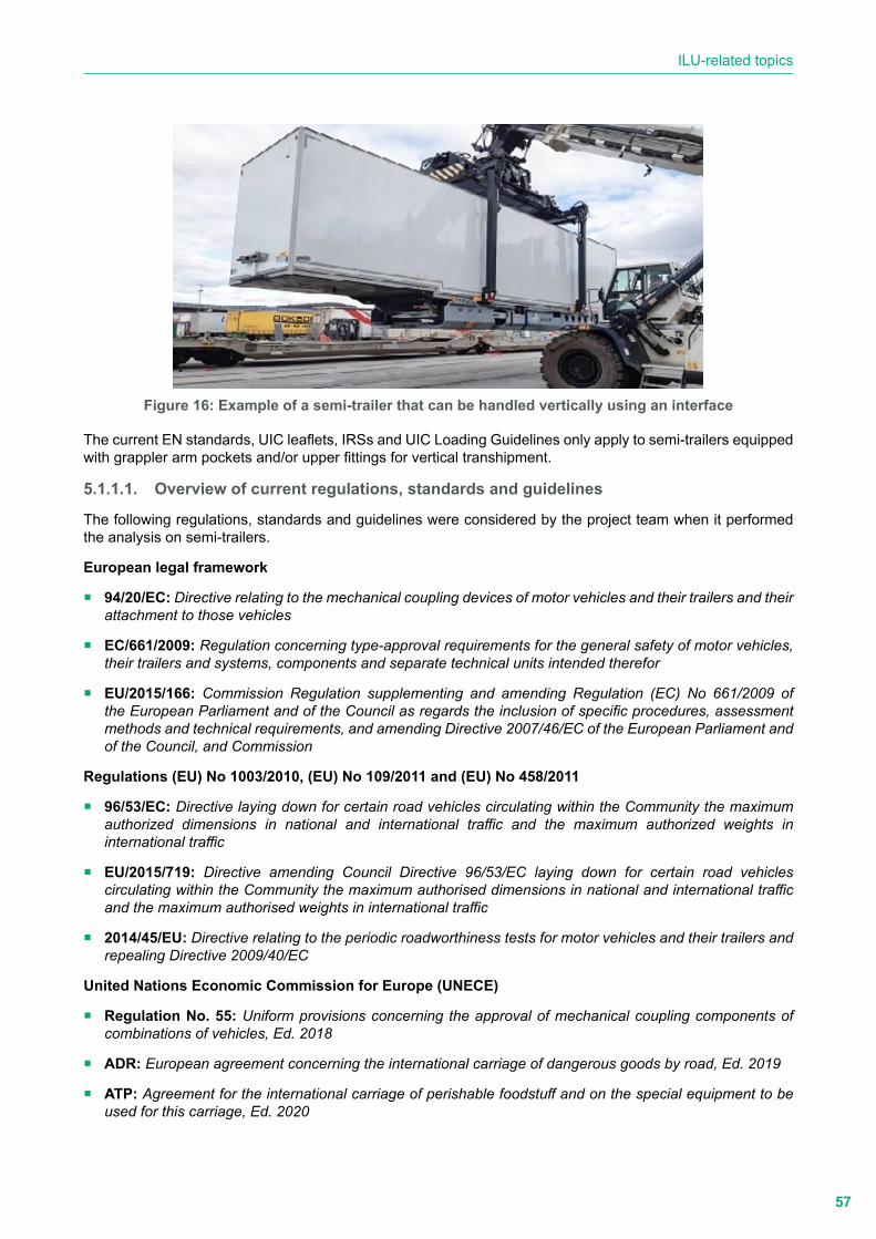
57
ILU-related topics
Figure 16: Example of a semi-trailer that can be handled vertically using an interface
The current EN standards, UIC leaflets, IRSs and UIC Loading Guidelines only apply to semi-trailers equipped with grappler arm pockets and/or upper fittings for vertical transhipment.
5.1.1.1. Overview of current regulations, standards and guidelines
The following regulations, standards and guidelines were considered by the project team when it performed the analysis on semi-trailers.
European legal framework
� 94/20/EC: Directive relating to the mechanical coupling devices of motor vehicles and their trailers and their attachment to those vehicles
� EC/661/2009: Regulation concerning type-approval requirements for the general safety of motor vehicles, their trailers and systems, components and separate technical units intended therefor
� EU/2015/166: Commission Regulation supplementing and amending Regulation (EC) No 661/2009 of the European Parliament and of the Council as regards the inclusion of specific procedures, assessment methods and technical requirements, and amending Directive 2007/46/EC of the European Parliament and of the Council, and Commission
Regulations (EU) No 1003/2010, (EU) No 109/2011 and (EU) No 458/2011
� 96/53/EC: Directive laying down for certain road vehicles circulating within the Community the maximum authorized dimensions in national and international traffic and the maximum authorized weights in international traffic
� EU/2015/719: Directive amending Council Directive 96/53/EC laying down for certain road vehicles circulating within the Community the maximum authorised dimensions in national and international traffic and the maximum authorised weights in international traffic
� 2014/45/EU: Directive relating to the periodic roadworthiness tests for motor vehicles and their trailers and repealing Directive 2009/40/EC
United Nations Economic Commission for Europe (UNECE)
� Regulation No. 55: Uniform provisions concerning the approval of mechanical coupling components of combinations of vehicles, Ed. 2018
� ADR: European agreement concerning the international carriage of dangerous goods by road, Ed. 2019
� ATP: Agreement for the international carriage of perishable foodstuff and on the special equipment to be used for this carriage, Ed. 2020

58
Comparative analysis of the combined transport usages and standards (CACTUS) - Final Report
� CSC: International Convention for Safe Containers, Ed. 2014
European Committee for Standardization (CEN)
� EN 12195-1+ 1/AC: Load restraining on road vehicles - Safety - Part 1: Calculation of securing forces, Ed. 2014/1.AC 2019
� EN 12195-2: Load restraint assemblies on road vehicles - Safety - Part 2: Web lashing made from man-made fibres, Ed. 2000
� EN 12195-3: Load restraint assemblies on road vehicles - Safety - Part 3: Lashing chains, Ed. 2001
� EN 12195-4: Load restraint assemblies on road vehicles - Safety - Part 4: Lashing steel wire ropes, Ed. 2003
� EN 12640: Intermodal loading units and commercial vehicles - Lashing points for cargo securing - Minimum requirements and testing, Ed. 2019
� EN 12641-1: Intermodal loading units and commercial vehicles - Tarpaulins - Part 1: Minimum requirements, Ed. 2019
� EN 12641-2: Intermodal loading units and commercial vehicles - Tarpaulins - Part 2: Minimum requirements for curtainsiders, Ed. 2019
� EN 12642: Securing of cargo on road vehicles - Body structure of commercial vehicles - Minimum requirements, Ed. 2016
� EN 13044-1: Intermodal Loading Units - Marking - Part 1: Markings for identification, Ed. 2011/AC 2014
� EN 13044-3: Intermodal Loading Units - Marking - Part 3: Markings of semi-trailers related to rail operation, Ed. 2011
� EN 16973: Road vehicles for combined transport - Semitrailer - Vertical transhipment, Ed. 2017
International Organization for Standardization (ISO)
� ISO 337 + Tech. Corr. 1: Road vehicles - 50 semi-trailer fifth wheel coupling pin - Basic and mounting and interchangeability dimensions, Ed. 1981/Tech. Corr. 1 Ed. 1990
� ISO 1161: Series 1 freight containers - Corner and intermediate fittings - Specifications, Ed. 2016
� ISO 1726-1: Road vehicles - Mechanical coupling between tractors and semi-trailers - Part 1: Interchangeability between tractors and semi-trailers for general cargo, Ed. 2000/Tech. Corr. 1 Ed. 2007
� ISO 1726-2: Road vehicles - Mechanical couplings between tractors and semi-trailers - Part 2: Interchangeability between low-coupling tractors and high-volume semi-trailers, Ed. 2007
� ISO 1726-3: Road vehicles - Mechanical couplings between tractors and semi-trailers - Part 3: Requirements for semi-trailer contact area to fifth wheel, Ed. 2010
� ISO 17025: General requirements for the competence of testing and calibration laboratories, Ed. 2017
� ISO 17065: Conformity assessment - Requirements for bodies certifying products, processes and services, Ed. 2012
International Union of Railways (UIC)
� IRS 50571-4: Wagons for combined transport - Vertical transhipment - Characteristics, Ed. 2020
� IRS 50596-5: Transport of road vehicles on wagons - Technical organisation - Conveyance of semi-trailers with P coding or N coding on recess wagons, Ed. 2020
� IRS 50596-6: Conditions for coding intermodal loading units in combined transport, combined transport

59
ILU-related topics
lines and wagons, Ed. 2018
� IRS 50596-7: Railway applications - Rolling stock - Conformity assessment - Requirements for bodies performing the certification of coding in accordance with UIC Leaflet 596-6 (Competent Authorities), Ed. 2017
� Loading Guidelines, Volume 1: Code of practice for the loading and securing of goods on railway wagons - Principles, Ed. 2020
� Loading Guidelines, Volume 2: Code of practice for the loading and securing of goods on railway wagons - Goods, Ed. 2020
GCU Bureau
� GCU: General Contract of Use for wagons, Ed. 2020
5.1.1.2. Overlaps, duplications and contradictions
The goal of the comparative analysis of the documents listed under Point 5.1.1.1 is the identification of:
� the requirements provided by each document for the selected parameters (see Clause a of the current point);
� overlaps, duplications, contradictions and gaps (see Clause b of the current point); and
� potential cross-referencing, areas of improvement and harmonisation needs (see Point 5.1.1.3).
a. Parameters and items
The analysis is focused on the following parameters:
1 Definitions
2 Classification
3 Dimensions
3.1 External dimensions
3.2 Internal dimensions
4 Ratings
8 Upper and bottom fittings
8.1 Upper (corner/intermediate) fittings: dimensions and location
8.3 Technical requirements
9 Grappler arm grooves: dimensions and location
10 Landing gear
15 Semi-trailer envelope
15.1 Lower part
15.2 Upper part
16 King pin
17 Steering wedge
18 Axle assembly and pneumatic suspension
19 Body structure
20 Tarpaulins
21 Ladders

60
Comparative analysis of the combined transport usages and standards (CACTUS) - Final Report
22 Walkways
23 Dimensions and position of supporting shoes (N technology)
24 Cargo securing
24.1 Anchor and lashing points
25 Load restraint and lashing devices for cargo securing
27 Refrigeration and heating equipment
28 Thermal characteristics of the isothermal body
29 Devices for hanging cargo
100 Tests
101 General
103 Lifting
103.1 Lifting from the grappler arm grooves
103.2 Lifting from the four upper fittings
109 Strength of end walls
109.1 Static tests
109.2 Dynamic tests
110 Strength of side walls
110.1 Static tests
110.2 Dynamic tests
111 Strength of the semi-trailer body structure
112 Strength of the roof
113 Strength of tarpaulins
114 Floor strength
117 Testing ladders
118 Testing walkways
119 Pressure tests
122 Testing supporting shoes (N technology)
123 Weatherproofness
124 Testing lashing points for cargo security
200 Design loadings
300 Identification and markings
300.1 Identification
300.2 Operational markings
400 Maintenance
500 Operational control
600 Certification
600.1 Codification
600.2 ILU approval
600.3 Coding plate delivery

61
ILU-related topics
b. Results of the dry and comparative analyses
The outputs of the dry analysis of the requirements on the relevant parameters (references to parameter numbers in brackets) provided by the selected documents are shown in Appendix B (ST_Dry analysis_sheet).
This point summarises the outputs of the dry and comparative analyses and is focused on the requirements provided by the reference documents, highlighting, for each parameter:
� design and testing requirements that are provided by IRS 50596-5 and/or EN 16973 and by the other selected reference documents;
� requirements that are not covered or referenced in IRS 50596-5 and/or EN 16973 but provided by one of the other analysed reference documents;
� documents that are not linked with any reference documents but need to be cross-referenced; and
� overlaps and possible contradictions between the requirements provided by the selected reference documents.
b.1. Summary (matrix table)
Table 2 provides a matrix compiling the parameters and the analysed reference documents.
� Requirements that are provided by the reference documents with no contradictions are identified by the
following marking in a green box: NC
� Contradictions are identified by the following marking in a red box: C
� Specific requirements provided by a standard are identified by the following marking in a light green box: SR
� Requirements provided by a standard and not considered in IRS 50596-5 or EN 16973 are identified by the following marking in an orange box: Not in EN 16973, IRS 50596-5
� Requirements provided by IRS 50596-5 for which there is a reference in EN 16973 and those provided by other relevant standards for which a reference was implemented in IRS 50596-5 and/or in EN 16973 are
identified by the following marking in a yellow box: A → EN 1XYZV
� Requirements that are not considered in the relevant reference documents are identified by the following
marking in a grey box: NR
� Requirements that are out of the scope of the relevant documents are identified by the following marking in
a light brown box: NA

62
Comparative analysis of the combined transport usages and standards (CACTUS) - Final Report
Tabl
e 2:
Sem
i-tra
ilers
: sum
mar
y m
atrix
(1/3
)
Para
met
er
EU le
gal
docs
ILU
ILU
sub
-ass
embl
ies,
com
pone
nts
and
acce
ssor
ies
Oth
er
96/5
3/EC
EU
20
15/7
19IR
S 50
596-
5EN
16
973
EN 1
2640
EN 1
2641
-1EN
126
41-2
EN 1
2642
EN
1304
4-1
EN
1304
4-3
EN
1219
5-1,
12
195-
2,
1219
5-3,
12
195-
4
IRS
5059
6-6
IRS
5059
6-7
GC
U
UIC
Loa
ding
G
uide
lines
, Vo
lum
es1
& 2
1C
CC
SRC
CSR
CC
SRC
CC
C2
NC
Not
in E
N 1
6973
NR
NR
NR
NR
NC
NC
NR
NC
NA
NA
NC
3C
NC
NC
NA
NA
NA
NA
NA
NA
NA
NA
NA
NA
NA
3.1
CN
CN
CN
AN
AN
AN
AN
AN
AN
AN
AN
AN
AN
A3.
2N
RN
RN
RN
AN
AN
AN
AN
AN
AN
AN
AN
AN
AN
A4
CN
RN
RN
AN
AN
AN
AN
AN
AN
AN
AN
AN
AN
A8
NA
Not
in E
N 1
6973
NA
NA
NA
NA
NA
NA
NA
NA
NA
NA
NA
8.1
NA
Not
in E
N 1
6973
NA
NA
NA
NA
NA
NA
NA
NA
NA
NA
NA
8.2
NA
Not
in E
N 1
6973
NA
NA
NA
NA
NA
NA
NA
NA
NA
NA
NA
9N
AA
→ E
N 1
6973
NC
NA
NA
NA
NA
NA
NA
NA
NA
NA
NA
NA
10N
AN
ot in
EN
169
73N
AN
AN
AN
AN
AN
AN
AN
AN
AN
AN
A15
NA
CC
NA
NA
NA
NA
NA
NA
NA
NA
NA
NA
NA
16N
AA
→ E
N 1
6973
NC
NA
NA
NA
NA
NA
NA
NA
NA
NA
NA
NA
17N
AA
→ E
N 1
6973
NC
NA
NA
NA
NA
NA
NA
NA
NA
NA
NA
NA
18N
AA
→ E
N 1
6973
NC
NA
NA
NA
NA
NA
NA
NA
NA
NA
NA
NA
19N
AC
CN
AN
AN
AA
→IR
S 50
596-
5N
AN
AN
AN
AN
AN
AN
A
20N
AN
ot in
EN
169
73N
AA
→IR
S 50
596-
5A
→IR
S 50
596-
5N
AN
AN
AN
AN
AN
AN
AN
A
21N
AN
RN
RN
AN
AN
AN
AN
AN
AN
AN
AN
AN
AN
A22
NA
NR
NR
NA
NA
NA
NA
NA
NA
NA
NA
NA
NA
NA
23N
AN
ot in
EN
169
73N
AN
AN
AN
AN
AN
AN
AN
AN
AN
AN
A24
NA
NR
NR
SRN
AN
AN
RN
AN
AN
AN
AN
AN
AN
A24
.1N
AN
RN
RSR
NA
NA
NR
NA
NA
NA
NA
NA
NA
NA
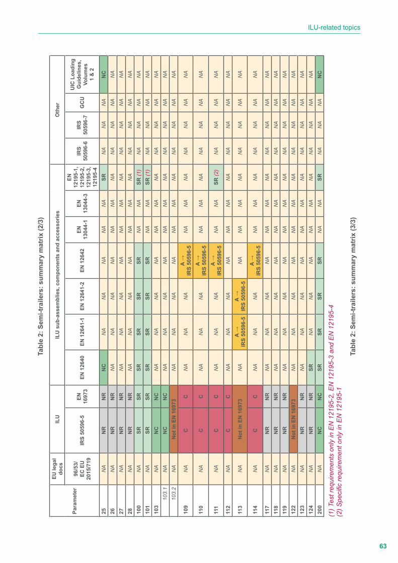
63
ILU-related topics
Tabl
e 2:
Sem
i-tra
ilers
: sum
mar
y m
atrix
(2/3
)
Para
met
er
EU le
gal
docs
ILU
ILU
sub
-ass
embl
ies,
com
pone
nts
and
acce
ssor
ies
Oth
er
96/5
3/EC
EU
20
15/7
19IR
S 50
596-
5EN
16
973
EN 1
2640
EN 1
2641
-1EN
126
41-2
EN 1
2642
EN
1304
4-1
EN
1304
4-3
EN
1219
5-1,
12
195-
2,
1219
5-3,
12
195-
4
IRS
5059
6-6
IRS
5059
6-7
GC
U
UIC
Loa
ding
G
uide
lines
, Vo
lum
es1
& 2
25N
AN
RN
RN
CN
AN
AN
AN
AN
ASR
NA
NA
NA
NC
26N
AN
RN
RN
AN
AN
AN
AN
AN
AN
AN
AN
AN
AN
A27
NA
NR
NR
NA
NA
NA
NA
NA
NA
NA
NA
NA
NA
NA
28N
AN
RN
RN
AN
AN
AN
AN
AN
AN
AN
AN
AN
AN
A10
0N
ASR
SRSR
SRSR
SRN
AN
ASR
(1)
NA
NA
NA
NA
101
NA
SRSR
SRSR
SRSR
NA
NA
SR (1
)N
AN
AN
AN
A10
3N
AN
CN
CN
AN
AN
AN
AN
AN
AN
AN
AN
AN
AN
A10
3.1
NA
NC
NC
NA
NA
NA
NA
NA
NA
NA
NA
NA
NA
NA
103.
2N
AN
ot in
EN
169
73N
AN
AN
AN
AN
AN
AN
AN
AN
AN
AN
A
109
NA
CC
NA
NA
NA
A →
IRS
5059
6-5
NA
NA
NA
NA
NA
NA
NA
110
NA
CC
NA
NA
NA
A →
IRS
5059
6-5
NA
NA
NA
NA
NA
NA
NA
111
NA
CC
NA
NA
NA
A →
IRS
5059
6-5
NA
NA
SR (2
)N
AN
AN
AN
A
112
NA
CC
NA
NA
NA
NA
NA
NA
NA
NA
NA
NA
NA
113
NA
Not
in E
N 1
6973
NA
A →
IRS
5059
6-5
A →
IRS
5059
6-5
NA
NA
NA
NA
NA
NA
NA
NA
114
NA
CC
NA
NA
NA
A →
IRS
5059
6-5
NA
NA
NA
NA
NA
NA
NA
117
NA
NR
NR
NA
NA
NA
NA
NA
NA
NA
NA
NA
NA
NA
118
NA
NR
NR
NA
NA
NA
NA
NA
NA
NA
NA
NA
NA
NA
119
NA
NR
NR
NA
NA
NA
NA
NA
NA
NA
NA
NA
NA
NA
122
NA
Not
in E
N 1
6973
NA
NA
NA
NA
NA
NA
NA
NA
NA
NA
NA
123
NA
NR
NR
NA
NA
NA
NA
NA
NA
NA
NA
NA
NA
NA
124
NA
NR
NR
SRN
AN
AN
AN
AN
AN
AN
AN
AN
AN
A20
0N
AN
CN
CSR
SRSR
SRN
AN
ASR
NA
NA
NA
NC
(1) T
est r
equi
rem
ents
onl
y in
EN
121
95-2
, EN
121
95-3
and
EN
121
95-4
(2) S
peci
fic re
quire
men
t onl
y in
EN
121
95-1
Tabl
e 2:
Sem
i-tra
ilers
: sum
mar
y m
atrix
(3/3
)
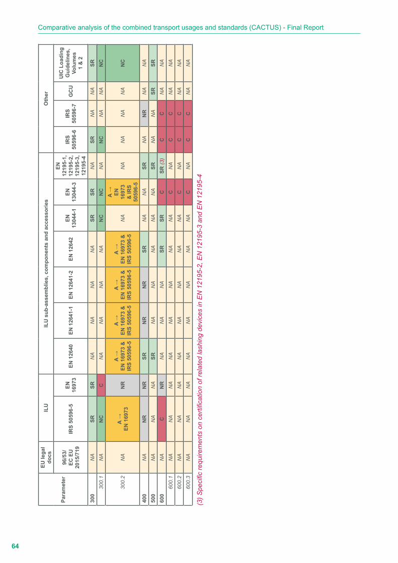
64
Comparative analysis of the combined transport usages and standards (CACTUS) - Final Report
Para
met
er
EU le
gal
docs
ILU
ILU
sub
-ass
embl
ies,
com
pone
nts
and
acce
ssor
ies
Oth
er
96/5
3/EC
EU
20
15/7
19IR
S 50
596-
5EN
16
973
EN 1
2640
EN 1
2641
-1EN
126
41-2
EN 1
2642
EN
1304
4-1
EN
1304
4-3
EN
1219
5-1,
12
195-
2,
1219
5-3,
12
195-
4
IRS
5059
6-6
IRS
5059
6-7
GC
U
UIC
Loa
ding
G
uide
lines
, Vo
lum
es1
& 2
300
NA
SRSR
NA
NA
NA
NA
SRSR
NA
SRN
AN
ASR
300.
1N
AN
CC
NA
NA
NA
NA
NC
NC
NA
NC
NA
NA
NC
300.
2N
AA
→EN
169
73N
RA
→EN
169
73 &
IR
S 50
596-
5
A →
EN 1
6973
&
IRS
5059
6-5
A →
EN 1
6973
&
IRS
5059
6-5
A →
EN 1
6973
&
IRS
5059
6-5
NA
A → EN
16
973
& IR
S 50
596-
5
NA
NA
NA
NA
NC
400
NA
NR
NR
SRN
RN
RSR
NA
NA
SRN
AN
RN
AN
A50
0N
AN
AN
ASR
NA
NA
NA
NA
NA
SRN
AN
ASR
SR60
0N
AC
NR
NA
NA
NA
SRSR
CSR
(3)
CC
NA
NA
600.
1N
AN
AN
AN
AN
AN
AN
AN
AC
NA
CC
NA
NA
600.
2N
AN
AN
AN
AN
AN
AN
AN
AC
NA
CC
NA
NA
600.
3N
AN
AN
AN
AN
AN
AN
AN
AC
NA
CC
NA
NA
(3) S
peci
fic re
quire
men
ts o
n ce
rtific
atio
n of
rela
ted
lash
ing
devi
ces
in E
N 1
2195
-2, E
N 1
2195
-3 a
nd E
N 1
2195
-4
65
ILU-related topics
b.2. Summary of the outputs of the performed analyses
The following section describes in detail - for each parameter - the requirements provided by the reference documentation highlighting any contradictions, overlaps and possible gaps. For ease of reading, a comprehensive description of each parameter has been added.
� Definitions (Parameter 1)
In all reference documents, some definitions and descriptions related to semi-trailers, although not in contradiction with each other, have been integrated considering the prevailing scope of the directives, regulations, standards and guidelines. To illustrate this, the definitions of ‘semi-trailer’ and ‘envelope’ are further described.
Semi-trailer
Directive 96/53/EC defines the semi-trailer as a: “vehicle intended to be coupled to a motor vehicle in such a way that part of it rests on the motor vehicle with a substantial part of its weight and of the weight of its load being borne by the motor vehicle and constructed and equipped for the carriage of goods”.
The suitability of semi-trailers for rail-road combined transport is not considered.
EU Directive 2015/719 amending Directive 96/53/EC introduces the following definition of intermodal transport operation:
a. the combined transport operations defined in Article 1 of Council Directive 92/106/EEC engaged in the transport of one or more containers or swap bodies, up to a total maximum length of 45 ft; or
b. transport operations engaged in the transport of one or more containers or swap bodies, up to a total maximum length of 45 ft, using waterborne transport, provided that the length of the initial or the final road leg does not exceed 150 km in the territory of the Union. The distance of 150 km referred to above may be exceeded to reach the nearest suitable transport terminal for the envisaged service in the case of:
i. vehicles complying with Point 2.2.2(a) or (b) of Annex I; or
ii. vehicles complying with Point 2.2.2(c) or (d) of Annex I, in cases where such distances are permitted in the relevant Member State.
For the purposes of Council Directive 92/106/EEC, ‘combined transport’ means the transport of goods between Member States where the lorry, trailer, semi-trailer, with or without tractor unit, swap body or container of 20 ft or more uses the road on the initial or final leg of the journey and, on the other leg, rail or inland waterway or maritime services where this section exceeds 100 km as the crow flies and make the initial or final road transport leg of the journey:
y between the point where the goods are loaded and the nearest suitable rail loading station for the initial leg, and between the nearest suitable rail unloading station and the point where the goods are unloaded for the final leg, or
y within a radius not exceeding 150 km as the crow flies from the inland waterway port or seaport of loading or unloading.
Even if semi-trailers are considered by Council Directive 92/106/EEC as combined transport units together with lorries, trailers, swap bodies or containers of 20 ft or more, Directive 96/53/EC and EU Directive 2015/719 do not identify semi-trailers as ILUs.
EN 16973, IRS 50596-5, IRS 50596-6, 50596-7, the GCU and UIC Loading Guidelines describe semi-trailers as “ILUs that are able to be transported by rail loaded on pocket wagons, are suitable for handling by gantry or mobile transhipment equipment and equipped with grappler arm grooves and upper fittings (this last requirement is present only in IRS 50596-5).”
EN 12641-1 and EN 12641-2 (Point 3.1) define semi-trailers as ILUs in the same way as containers, swap bodies, road-trailers and commercial vehicles suitable for intermodal transport.

66
Comparative analysis of the combined transport usages and standards (CACTUS) - Final Report
EN 13044-1 and EN 14044-3 (Point 3.1) define semi-trailers as ILUs suitable for European intermodal transport on road, rail, inland waterway and sea, but not as ISO containers according to ISO 830.
EN 12640 and EN 12195-1 to 5 provide specific definitions of items related to their application field and do not define semi-trailers.
Envelope
The boundary of the space which can be filled by the semi-trailer in the stipulated loading position on the pocket wagon is known as:
y ‘swept envelope’ in EN 16973; and
y ‘envelope’ in IRS 50596-5 and IRS 50596-6.
The harmonisation of terms and definitions used in all the relevant technical documents is necessary.
� Classification (Parameter 2)
There are no contradictions and overlaps between Directive 96/53/EC, Directive (EU) 2015/719, EN 13044-1, EN 13044-3, IRS 50596-5, IRS 50596-6 and UIC Loading Guideline Volume 2. In particular:
y Directive 96/53/EC, which applies to all road vehicles, classifies freight motor vehicles into Categories N2 and N3 and semi-trailers into Categories O3 and O4.
y In IRS 50596-5, IRS 50596-6 and UIC Loading Guidelines, Volume 2, semi-trailers suitable for vertical transhipment and equipped with grappler arm pockets and/or upper fittings are classified according to the wagon compatibility code (WCC) and the compatibility of their envelope with that of the wagon (semi-trailer envelope compatibility code).
y EN 13044-1 and EN 13044-3 do not provide requirements for the classification of semi-trailers and refer to IRS 50596-6.
No classification of semi-trailers is made in EN 16793.
The classification of semi-trailers is out of the scope of EN 12640, EN 12641-1, EN 12641-2, EN 12642 and EN 12195-1 to 2. The classification provided by these standards concerns only the typologies of concerned sub-assemblies and components.
The classification of semi-trailers, including their sub-assemblies and components, is out of the scope of IRS 50596-7, the GCU and UIC Loading Guidelines, Volume 1.
� Dimensions (Parameter 3)
The provision of requirements on the dimension of semi-trailers is out of the scope of EN 12640, EN 12641-1, EN 12641-2, EN 12642, EN 12195-1 to 5, EN 13044-1, EN 13044-3, IRS 50596-5,
IRS 50596-6, IRS 50596-7, the GCU and UIC Loading Guidelines, Volumes 1 & 2.
Directive (EU) 2015/719 amending Directive 96/53/EC considers the transport of one or more containers or swap bodies, up to a total maximum length of 45 ft. In this case, the maximum authorised length of articulated vehicles and the maximum authorised distance between the axle of the king pin and the rear of the semi-trailer may be exceeded by 0.15 m (Article 10c).
These provisions do not apply to other types of semi-trailers because, unlike ISO containers and swap-bodies, they are not considered in both directives as ILUs.
� External dimensions (Parameter 3.1)
y Maximum length,
y Maximum width,
y Maximum height,
67
ILU-related topics
y Maximum distance between the king-pin axis and the rear part of the semi-trailer, and
y Maximum distance between the king-pin axis and the front part of the semi-trailer.
Maximum length
y Directive 96/53/EC, Annex I - Point 1.1
• Articulated vehicles = 16.50 m
• Road trains = 18.75 m
y Directive (EU) 2015/719, Article 10c amending Point 1.1 of Directive 96/53/EC, Annex I Vehicles carrying 45 ft containers and 45 ft swap bodies
• Articulated vehicles = 16.50 m
• Road trains = 18.90 m
Maximum width
Directive 96/53/EC, Annex I - Point 1.2 (as amended by Directive (EU) 2015/719, Article 10j):
a. All vehicles except those referred to Point (b) = 2.55 m
b. Superstructure of conditioned vehicles or conditioned containers or swap bodies transported by vehicles = 2.60 m
Maximum height
Directive 96/53/EC, Annex I - Point 1.3: All vehicles = 4.00 m.
Maximum distance between the king-pin axis and the rear part of the semi-trailer
y Directive 96/53/EC, Annex I - Point 1.6
• Articulated vehicles = 12.00 m
y Directive (EU) 2015/719, Article 10c amending Point 1.6 of Directive 96/53/EC, Annex I
• Articulated vehicles carrying 45 ft containers and 45 ft swap bodies = 12.15 m
Maximum distance between the king-pin axis and the front part of the semi-trailer
y Directive 96/53/EC, Annex I - Point 1.6: All semi-trailers = 2.04 m
There are no contradictions between EN 16973 and IRS 50596-5 on the dimensions of the front free space. The goose-neck contour shall be compliant with ISO 1726-1 and ISO 1726-3.
� Internal dimensions (Parameter 3.2)
No requirements on internal dimensions are provided in the reference documents.
� Ratings (Parameter 4)
Directive (EU) 2015/719 amending Directive 96/53/EC considers the intermodal transport of one or more containers or swap bodies, up to a total maximum length of 45 ft. In this case, the following provisions on the maximum authorised weight apply:
y 2-axle motor vehicles with 3-axle semi-trailer carrying, in intermodal transport operations, one or more containers or swap bodies, up to a total maximum length of 45 ft: 42 t (40 t for other types of semi-trailers).
y 3-axle motor vehicles with 2- or 3-axle semi-trailer carrying, in intermodal transport operations, one or more containers or swap bodies, up to a total maximum length of 45 ft: 44 t (40 t for other types of semi-trailers).
68
Comparative analysis of the combined transport usages and standards (CACTUS) - Final Report
These provisions do not apply to semi-trailers because, unlike ISO containers and swap-bodies, they are not considered in both directives as ILUs.
y Maximum authorised weight of semi-trailers, and
y Maximum authorised axle weight of semi-trailers.
Maximum authorised weight of semi-trailers
y Directive 96/53/EC, Annex I, Point 2
Maximum authorised weight of articulated vehicles (motor vehicle + semi-trailer)
• 2-axle motor vehicle + 2-axle semi-trailer = 36 t
• 2-axle motor vehicle + 2-axle semi-trailer = 38 t (18 t + 20 t) [*]
• 2-axle motor vehicle + 3-axle semi-trailer = 40 t
• 3-axle motor vehicle + 2- or 3-axle semi-trailer = 40 t
• 3-axle motor vehicle + 2- or 3-axle semi-trailer = 44 t (when carrying one 40 ft ISO container) [*] distance between the axles of the semi-trailer = 1.8 m
y Directive (EU) 2015/719, Article 10j
Maximum authorised weight of articulated vehicles (motor vehicle + semi-trailer) when carrying one or more swap bodies and ISO containers up to total maximum length ≤ 45 ft:
• 2-axle motor vehicle + 3-axle semi-trailer = 42 t
• 3-axle motor vehicle + 2- or 3-axle semi-trailer = 44 t
Maximum authorised axle weight of semi-trailers.
y In accordance with Directive 96/53/EC, Annex I, depending on the distance between the axles of the semi-trailer (d), the sum of the axle weights shall not exceed the following values.
• Tandem axles (Point 3.2): d ˂ 1.0 m → 11.0 t
1.0 m ≤ d ˂ 1.3 m → 16.0 t
1.3 m ≤ d ˂ 1.8 m → 18.0 t d ≥ 1.8 m → 20.0 t
• Tri-axles (Point 3.3): d ≤ 1.3 m → 21.0 t
1.3 m ˂ d ≤ 1.8 m → 24.0 t
The requirements on this specific item were not modified by Directive (EU) 2015/719.
No specific requirements in EN 16973, IRS 50596-5 and UIC Loading Guidelines.
� Upper and bottom fittings (Parameter 8)
The provision of the requirements on the dimensions, location and technical requirements of upper and bottom fittings is out of the scope of Directive 96/53/EC, Directive (EU) 2015/719, EN 12640, EN 12641-1, EN 12641-2, EN 12642, EN 12195-1 to 5, EN 13044-1, EN 13044-3, IRS 50596-6,
IRS 50596-7, the GCU and UIC Loading Guidelines, Volumes 1 & 2.
� Upper (corner/intermediate) fittings: dimensions, position and technical requirements(Parameters 8, 8.1 and 8.3)

69
ILU-related topics
According to IRS 50596-5, as an alternative to grab handling grooves, semi-trailers may be provided with upper corner fittings, which shall comply with the requirements of IRS 50592 and ISO 1161.
The position of the upper corner fittings is defined in Appendix A.3.
No requirements for upper corner fittings are provided in EN 16973 (only grappler grooves are foreseen).
� Grappler arm grooves: dimensions and location (Parameter 9)
The provision of requirements on the dimensions and location of the grappler arm grooves is out of the scope of Directive 96/53/EC, Directive (EU) 2015/719, EN 12640, EN 12641-1, EN 12641-2,
EN 12642, EN 12195-1 to 5, EN 13044-1, EN 13044-3, IRS 50596-6, IRS 50596-7, the GCU and UIC Loading Guidelines, Volumes 1 & 2.
IRS 50596-5, in addition to the requirements in common with EN 16973, requires that the distance between the grab handling grooves underside and the wagon solebar shall be at least 100 mm.
NB This requirement was introduced in IRS 50596-5 to ensure safety during loading and unloading of semi-trailers and to prevent damage to the wagon structure.
� Landing gear (Parameter 10)
The term ‘landing gear’ identifies the vertical support mounted on a semi-trailer and serving as a bearing point for the vehicle when it is uncoupled. The landing gear is also used for hitching or unhitching a semi-trailer to or from a tractor to reduce the pressure that holds them together.
The provision of requirements on landing gear is out of the scope of Directive 96/53/EC, Directive (EU) 2015/719, EN 12640, EN 12641-1, EN 12641-2, EN 12642, EN 12195-1 to 5, EN 13044-1,
EN 13044-3, IRS 50596-6, IRS 50596-7, the GCU and UIC Loading Guidelines, Volumes 1 & 2.
According to IRS 50596-5, it shall be possible to manipulate the landing gear when the grab handles are in the grab handling groves.
There are no requirements in EN 16973.
� Semi-trailer envelope (Parameter 15)
The position of semi-trailers on compatible pocket wagons depends (see Figure 17) on:
y the location of the axle-assembly in relation to the king pin position;
y the type of axle assembly (2- or 3-axles); and
y the distance between the axles (depending on the maximum allowable axle-load).
Figure 17: Positioning of semi-trailers on compatible wagons depending on their design
characteristics

70
Comparative analysis of the combined transport usages and standards (CACTUS) - Final Report
While the maximum allowable dimensions of road vehicles (including semi-trailers) are fixed by Directive 96/53/EC amended by Directive (EU) 2015/719 thus ensuring road interoperability in EU Member States, the choice of axle assembly type and its location depends on the design characteristics of the semi-trailer.
The term ‘semi-trailer envelope’ identifies the boundary of the volume that can be occupied by different types of semi-trailers when they are loaded on compatible pocket wagons without interference with the structure of the pocket wagon and in accordance with their Combined Transport Profile number. The semi-trailer envelope may be divided into a lower and an upper part.
y The lower part includes the semi-trailer components located under the level of the lifting surfaces of the grappler arm grooves. It is essential for the assessment of the compatibility of the semi-trailer with the pocket wagon and for the allocation of the envelope compatibility code on the coding plate.
y The upper part includes the superstructure of the semi-trailer and must be considered for the allocation of the Combined Transport Profile number to the semi-trailer.
Figure 18 shows an example of a semi-trailer envelope with:
y the lower part marked in red; and
y the upper part marked in green.
Figure 18: Semi-trailer envelope
The provision of requirements on the semi-trailer envelope is out of the scope of Directive 96/53/EC, Directive (EU) 2015/719, EN 12640, EN 12641-1, EN 12641-2, EN 12642, EN 12195-1 to 5, EN 13044-1, EN 13044-3, IRS 50596-6, IRS 50596-7, the GCU and UIC Loading Guidelines, Volumes 1 & 2.
The following contradictions exist between the requirements provided by EN 16875 and IRS 50596- 5 on semi-trailer envelope compatibility with related pocket wagons and the dedicated CTP of the line.
71
ILU-related topics
y Upper part (Parameter 15.1)
According to EN 16973:
• semi-trailers may not exceed the envelope defined in Annex 1; and
• the transversal dimensions of semi-trailers should be compatible with CTPs defined by UIC Leaflet 596-6.
In contradiction with the above-mentioned requirement, according to IRS 50596-6:
• semi-trailers shall not exceed the boundary of the envelope identified by its envelope compatibility code; and
• the transversal dimensions of semi-trailers shall be compatible with the CTPs defined by IRS 50596-6.
y Lower part (Parameter 15.2)
Regarding the lower part of the semi-trailer envelope in the stipulated loading position.
• According to EN 16973, the semi-trailer may not exceed the swept envelope (envelope in IRS 50596-5) defined in Annex 1.
• In contradiction with the above-mentioned requirement, according to IRS 50596-5, the compliance of the dimensions and boundary of the relevant envelope profile is mandatory for all CT semi-trailers.
� King pin (Parameter 16)
The provision of requirements on the king pin is out of the scope of Directive 96/53/EC, Directive (EU) 2015/719, EN 12640, EN 12641-1, EN 12641-2, EN 12642, EN 12195-1 to 5, EN 13044-1,
EN 13044-3, IRS 50596-6, IRS 50596-7, the GCU and UIC Loading Guidelines, Volumes 1 & 2.
Regulation (EU) 661/2009 repealing Directive 94/20/EC (see Directive 94/20/EC:2014) and then amended and supplemented by Regulation (EU) 166/2015 requires the mandatory application of UNECE Regulation No. 55 to mechanical coupling components of road vehicles of categories N and O.
For king pin requirements, UNECE Regulation No. 55 (paragraph 8.1) refers to ISO 337. EN 16973, Point 4.2 refers to Directive 94/20/EC:2014.
IRS 50596-5 provides the following requirements in addition to those laid down in EN 16973:
y Reference to ISO 337 for P coded semi-trailers.
y Specific requirements for N coded semi-trailers.
NB UNECE Regulation No. 55, Point 7.4 also provides requirements for locking devices to prevent the uncoupling of the king pin from the coupling plate (road saddle surface).
y The king pin shall be locked in the coupled position by two positive mechanical locking devices each of which shall remain effective should the other failure.
y The primary locking device shall operate automatically but the secondary locking device may either be automatic or be engaged manually.
y The secondary locking device may be designed to work in conjunction with the primary device and provide an additional positive mechanical lock for the primary device. It shall only be possible to engage the secondary locking device if the primary device is properly engaged.
y It shall not be possible for the locking devices to be released inadvertently. Release shall require intentional action by the driver or operator of the vehicle.

72
Comparative analysis of the combined transport usages and standards (CACTUS) - Final Report
y The closed and locked position of the coupling shall be indicated visually by a mechanical device, and it shall be possible to verify the position of the indicator by feel, for example, to allow the position to be checked during darkness.
y The indication device shall indicate the engagement of both primary and secondary locking devices; however, it is sufficient for the engagement of only one device to be indicated if, in this case, the engagement of the other device is a simultaneous and inherent feature of the design.
According to Point 7.5:
y In the closed position the operating devices or release mechanisms shall be prevented from being operated inadvertently or accidentally. The locking system shall be such as to require positive, conscious action to release the locking device to operate coupling release mechanism.
IRS 50571-4, Points 3.4.2 and 3.4.3 provide the requirements for locking devices to prevent the uncoupling of the king pin from the coupling plate and for its visual check.
� Steering wedge (Parameter 17)
Steering wedges are devices mounted on semi-trailers which control positive steering of the trailer in conjunction with the fifth wheel coupling.
The provision of requirements on the steering wedge is out of the scope of Directive 96/53/EC, Directive (EU) 2015/719, EN 12640, EN 12641-1, EN 12641-2, EN 12642, EN 12195-1 to 5, EN 13044-1, EN 13044-3, IRS 50596-6, IRS 50596-7, the GCU and UIC Loading Guidelines, Volumes 1 & 2.
Directive 94/20/EC was repealed by Regulation (EU) 661/2009 (ref. Directive 94/20/EC:2014) then amended and supplemented by Regulation (EU) 166/2015. According to this regulation the application of the UNECE Regulation No. 55 is mandatory for mechanical coupling components of road vehicles of categories N and O.
According to UNECE Regulation No. 55, Annex 5 (paragraph 7.8), steering wedges shall be spring mounted.
The dimensions, functions and mandatory operational requirements of the steering wedge are specified in paragraphs 7.8.1 and 7.8.2.
No contradictions. In addition to the requirements laid down in EN 16973, IRS 50596-5 requires the mandatory identification of semi-trailers equipped with a steering wedge by a specific marking.
� Axle assembly and pneumatic suspension (Parameter 18)
The provision of requirements on the axle assembly and pneumatic suspension is out of the scope of Directive 96/53/EC, Directive (EU) 2015/719, EN 12640, EN 12641-1, EN 12641-2, EN 12642, EN 12195-1 to 5, EN 13044-1, EN 13044-3, IRS 50596-6, IRS 50596-7, the GCU and UIC Loading
Guidelines, Volumes 1 & 2.
Additional requirements to those laid out in EN 16973 are provided by IRS 50596-5:
y P and N coded semi-trailers:
• Position of the device for releasing brakes (mandatory).
• Functions and position of the central draining valve (mandatory).
• Marking of the central draining valve (recommended).
y N coded semi-trailers only:
• Automatic deflation of the suspension before loading the semi-trailer on the wagon (recommended).
73
ILU-related topics
� Body structure (Parameter 19)
The provision of requirements on the semi-trailer body structure is out of the scope of Directive 96/53/EC, Directive (EU) 2015/719, EN 12640, EN 12641-1, EN 12641-2, EN 12195-1 to 5, EN 13044-1, EN 13044-3, IRS 50596-6, IRS 50596-7, the GCU and UIC Loading Guidelines, Volumes 1 & 2.
EN 12642 defines the minimum requirements for standard vehicles bodies (Code L) and reinforced vehicle bodies (Code XL) and specifies appropriate tests (see also Parameters 109, 110 and 111).
It applies to the following types of body structures:
y Box type
y Drop side body with side and tail boards without tarpaulin cover
y Drop side body with side and tail boards with tarpaulin cover
y Curtainsider
A calculation for the complete system, consisting of front, rear and side walls, roof, and floor, is necessary for the entire structure even if individual components have been taken from sample structures which have been calculated or tested with positive results before.
The current edition of IRS 50596-5 refers to the requirements in EN 12642.
According to Point 1.2.8.2, the semi-trailer body structure for railway transport shall be compliant with EN 12642, Code XL.
Point 1.2.8.2 also provides requirements for:
y securing devices for roof and tarpaulins designed to remain closed during transport; and
y the mechanical locking system of roof support pillars equipping semi-trailers with a height- adjustable roof for loading purposes.
According to Point 1.2.8.2.1, the superstructure of semi-trailers with special equipment for transporting cargo subject to compacting must be certified for the respective load and must not exceed the semi-trailer’s overall maximum width.
EN 16973 refers to UIC Leaflet 596-5. This document has been updated, introducing, inter alia, the above-mentioned requirements, and migrated into IRS 50596-5.
� Tarpaulins (Parameter 20)
The provision of requirements on tarpaulins is out of the scope of Directive 96/53/EC, Directive (EU) 2015/719, EN 12640, EN 12642, EN 12195-1 to 5, EN 13044-1, EN 13044-3, IRS 50596-6,
IRS 50596-7, the GCU and UIC Loading Guidelines, Volumes 1 & 2.
EN 12641-1 provides the following minimum requirements regarding the rigidity of tarpaulins used on semi-trailers for road and road/rail combined transport and of their attachments:
y Materials (Point 4.3)
y Construction (Point 4.4)
y Fixation of tarpaulins (Point 4.5)
EN 12641-2 provides minimum requirements for curtainsiders, in particular:
y Materials to be used for tarpaulins (Point 4.2)
y Tarpaulin reinforcements (Point 4.3)

74
Comparative analysis of the combined transport usages and standards (CACTUS) - Final Report
y Belt hooks (Point 4.4)
y Vertical tensioning devices (Point 4.5.2)
y Horizontal tensioning devices (Point 4.5.3)
Tarpaulins compliant with this standard only work with a semi-trailer body structure according to EN 12642.
There are no requirements in EN 16973.
The following requirements are not present in EN 16973 but are provided by IRS 50596-5, Point 1.2.8.3:
Semi-trailers with tarpaulins and tension belts:
y Tarpaulins and tension belts shall meet the strength and securing conditions defined in EN 12641-1 and EN 12641-2.
y Mandatory use of tensioning systems (ratchet and belts) tested as per EN 12641-2.
Semi-trailers with side walls and tarpaulins:
y Tarpaulins shall meet the strength and securing conditions defined in EN 12641-1.
y Tension belt and locks shall be compliant with EN 12641-2.
Semi-trailers with height-adjustable tarpaulins:
y These shall meet the strength and securing conditions defined in EN 12641-1.
y Tensioning closures shall be compliant with EN 12642-2 (maximum distance between two tensioners: 1,200 mm)
y Mandatory equipment of roof columns with a mechanical safety device ensuring that the roof does not exceed the maximum permitted height.
In all cases, elastic tarpaulins fastenings are not permitted.
There are no contradictions between EN 12641-1, EN 12641-2 and IRS 50596-5.
� Ladders (Parameter 21)
The provision of requirements on ladders is out of the scope of Directive 96/53/EC, Directive (EU) 2015/719, EN 12640, EN 12641-1, EN 12641-2, EN 12642, EN 12195-1 to 5, EN 13044-1,
EN 13044-3, IRS 50596-6, IRS 50596-7, the GCU and UIC Loading Guidelines, Volumes 1 & 2. No requirements on ladders are provided in EN 16973 and IRS 50596-5.
Requirements on ladders are provided in EN 1432 (swap tanks) and ISO 1496-3 (tank containers).
� Walkways (Parameter 22)
The provision of requirements on walkways is out of the scope of Directive 96/53/EC, Directive (EU) 2015/719, EN 12640, EN 12641-1, EN 12641-2, EN 12642, EN 12195-1 to 5, EN 13044-1, EN 13044-3, IRS 50596-6, IRS 50596-7, the GCU and UIC Loading Guidelines, Volumes 1 & 2. No requirements on walkways are provided in EN 16973 and IRS 50596-5.
Requirements on walkways are provided in EN 1432 (swap tanks) and ISO 1496-3 (tank containers).
� Supporting shoes: dimensions and location (Parameter 23)
The provision of requirements on ladders is out of the scope of Directive 96/53/EC, Directive (EU) 2015/719, EN 12640, EN 12641-1, EN 12641-2, EN 12642, EN 12195-1 to 5, EN 13044-1, EN 13044-3, IRS 50596-6, IRS 50596-7, the GCU and UIC Loading Guidelines, Volumes 1 & 2. There are no requirements in EN 16973.
Additional mandatory requirements are provided in IRS 50596-5 for N coded semi-trailers.
75
ILU-related topics
� Cargo securing (Parameter 24)
The provision of requirements on this parameter is out of the scope of Directive 96/53/EC, Directive (EU) 2015/719, EN 12641-1, EN 12641-2, EN 12195-1 to 5, EN 13044-1, EN 13044-3,
IRS 50596-6, IRS 50596-7, the GCU and UIC Loading Guidelines, Volumes 1 & 2.
� Lashing points (Parameter 24.1)
In accordance with EN 12640, the term ‘lashing points’ identifies security devices located as near as possible to the platform longitudinal edges and/or integrated in the outer frame to which the lashing equipment may be directly attached.
EN 12640 does not distinguish between lashing points and anchor points, unlike ISO 1496-1 and 1496-5 where:
y anchor points are securing devices located in the base structure of the container; and
y lashing points are securing devices located in any part of the container other than their base structure.
EN 12640 provides requirements on:
y single lashing points: design and strength;
y multi-point lashing systems: design and strength;
y number and layout of lashing points;
y lashing points in the front wall; and
y optional single lashing points or multi-point lashing systems.
There are no specific requirements for lashing points for cargo securing in EN 16973, EN 12642 and IRS 50596-5 and no reference to EN 12640.
� Lashing devices for cargo securing (Parameter 25)
The term ‘lashing device’ identifies the equipment to be attached to the lashing points in order to secure the cargo on an ILU and consisting of tensioning elements (e.g. webbing, chain, wire, rope, etc.), tensioning devices (e.g. wrench, ratchet, spanner, tension jack, etc.) and connecting components, if required (e.g. hook, terminal link, etc.).
The provision of requirements on this parameter is out of the scope of Directive 96/53/EC, Directive (EU) 2015/719, EN 12641-1, EN 12641-2, EN 12642, EN 13044-1, EN 13044-3,
IRS 50596-6, IRS 50596-7, the GCU and UIC Loading Guidelines, Volume 1.
No specific requirement is provided in EN 16973 and IRS 50596-5. EN 12640 refers to:
y EN 12195-2: Web lashing made from man-made fibres;
y EN 12195-3: Lashing chains; and
y EN 12195−4: Lashing steel wire ropes.
EN 12195-1 applies to load restraining on ILUs designed for rail transport and provides:
y method calculations;
y test requirements; and
y acceleration values for cargo on semi-trailers during rail transport.
According to EN 12195-1, Table 3: Acceleration coefficients cx, cy and cz during rail transport

76
Comparative analysis of the combined transport usages and standards (CACTUS) - Final Report
Securing inAcceleration coefficients
cx, longitudinallycy, transversely
cz, minimum vertically downSliding Tilting Sliding Tilting
Longitudinal direction 1.0 0.6 - 1.0 1.0
Transverse direction - - 0.5 0.7 1.0
EN 12195-2 to 4 apply to:
y web lashing made from man-made fibres (EN 12195-2);
y lashing chains (EN 12195-3); and
y lashing steel wire ropes (EN 12195−4).
For each lashing device, the EN standards:
y specify safety requirements and methods for testing; and
y deal with the significant hazards which could occur when web lashings are in use as intended and under conditions foreseen by the manufacturer.
No reference is provided in EN 16973 and IRS 50596-5 to EN 12195-1 to 4.
UIC Loading Guidelines, Volume 1, Point 1.3 sets out the value of the stresses arising during rail transport:
y Longitudinal acceleration = 1.0 g
y Lateral acceleration = 0.5 g
y Vertical acceleration = 0.3 g (in contradiction with EN 12195-1, Table 3)
UIC Loading Guidelines, Volume 2 refers to:
y EN 12195-1 for the identification of stresses during transport/relevant accelerations (Point 9.0.1) and for the determination of the friction coefficients (Point 9.0.6); and
y EN 12195-1 to 4 as applicable regulations for load securing (Point 9.0.1).
There are no contradictions between UIC Loading Guidelines, Volume 2 and EN 12195-1 to 4.
� Refrigeration and heating equipment (Parameter 27)
EN 16973 and IRS 50596-5 do not provide any requirements on the design and performance of the refrigeration and thermal equipment of thermal semi-trailers, nor any reference to the Agreement on the international carriage of perishable foodstuff and on the special equipment to be used for such carriage (ATP) published by UNECE.
Requirements on this item are out of the scope of the remaining reference documents.
� Thermal characteristics of the isothermal body (Parameter 28)
EN 16973 and IRS 50596-5 do not provide any requirements on the thermal characteristics of the isothermal body (global thermal transmission coefficient K) of thermal semi-trailers and nor any reference to the ATP.
Requirements on this item are out of the scope of the remaining reference documents.
� Devices for hanging cargo (Parameter 29)
EN 16973 and IRS 50596-5 do not provide any requirements on devices for hanging cargo in thermal semi-trailers.

77
ILU-related topics
Requirements on this item are out of the scope of the remaining reference documents.
� Tests (Parameter 100)
The provision of test requirements is out of the scope of Directives 96/53/EC, Directive (EU) 2015/709, EN 13044-1, 13044-3, IRS 50596-6, IRS 50596-7, the GCU and UIC Loading Guidelines, Volumes 1 & 2.
Testing requirements for semi-trailers suitable for railway transport are provided by EN 16973 and IRS 50596-5 (see Parameters 103 to 123).
These tests, except the weatherproofness test (Parameter 123), are relevant for ensuring safety in the various phases of railway operation (handling in terminals, conveyance, inspection, etc.). The weatherproofness test is linked to the performance quality of semi-trailers.
EN 12640, EN 12641-1, 12641-2 and 12195-1 to 4 provide specific requirements for ILU components and equipment (lashing points, tarpaulins and lashing devices for cargo securing).
EN 12642 provides testing requirements for ILU body structures.
� General (Parameter 101)
After testing, the semi-trailer shall not exhibit any permanent deformations or other changes which would prevent its use in accordance with regulations; the dimensions required for handling, securing and transhipment shall be maintained.
The strength of semi-trailers may be assessed through tests and/or calculations based on verifiable procedures (i.e. FEM), but the reference documents do not provide any requirements on the CAD/FEM models to be used or on the documentation (i.e. digital 3D wagon drawings) to be provided by wagon manufacturers upon the request of semi-trailer manufacturers.
� Lifting (Parameter 103)
Lifting tests shall be carried out to prove the ability of a semi-trailer to withstand being lifted, from the grappler arm pockets or from the upper fittings, with the lifted forces applied as specified by EN 16973 and IRS 50596-5.
� Lifting from the grappler arm grooves (Parameter 103.1)
There is no contradiction between EN 16973 and IRS 50596-5: Test load: 1.25 R for at least 5 minutes.
� Lifting from four upper fittings (Parameter 103.2)
A specific additional requirement is provided in IRS 50596-5: Test load: 1.25 R for at least 5 minutes.
EN 16973 does not provide any requirements on this parameter.
� Strength of end walls (Parameter 109)
EN 16973 refers to UIC Leaflet 596-5. This document has been updated and migrated into IRS 50596-5.
� Static tests (Parameter 109.1)
Front walls:
According to IRS 50596-5, as part of the body structure, static tests shall be performed as per EN 12642 (Code XL), Points 5.2.1 and 5.2.3 and Annex A.
Rear walls:
According to IRS 50596-5, as part of the body structure, static tests shall be performed as per Points 5.2.1 and 5.2.4 and Annex A.
78
Comparative analysis of the combined transport usages and standards (CACTUS) - Final Report
� Dynamic tests (Parameter 109.2)
Front and rear walls:
According to IRS 50596-5, as part of the body structure, front walls shall be tested as per EN 12642, Code XL. In this case, EN 12642, Point 5.3.1 and Annex B apply.
� Strength of side walls (Parameter 110)
EN 16973 refers to UIC Leaflet 596-5. This document has been updated and migrated into IRS 50596-5.
� Static tests (Parameter 110.1)
According to IRS 50596-5, as part of the body structure, static tests shall be performed as per EN 12642 (Code XL), Points 5.2.1 and 5.2.5 and Annex A.
� Dynamic tests (Parameter 110.2)
According to IRS 50596-5, as part of the body structure, front walls shall be tested as per EN 12642, Code XL. In this case, EN 12642, Point 5.3.1 and Annex B apply.
� Strength of the semi-trailer body structure (Parameter 111)
EN 16973 refers to UIC Leaflet 596-5. This document has been updated and migrated into IRS 50596-5.
According to IRS 50596-5:
y Point 1.2.8.2: Vehicle body structures shall be tested in accordance with EN 12642, Code XL.
y Point 1.2.8.2.1: The superstructure of semi-trailers with special equipment for transporting cargo subject to compacting shall be checked according to Annex A of EN 12642 and certified for the respective load and must not exceed the semi-trailer’s overall maximum width.
� Strength of the roof (Parameter 112)
EN 16973 refers to UIC Leaflet 596-5. This document has been updated and migrated into IRS 50596-5.
According to IRS 50596-5, Point 1.2.8.2:
A load of 300 kg from above and below and distributed on a flat continuous surface measuring 700 mm x 300 mm. (In EN standards on swap bodies, the surface dimensions are 600 mm x 300 mm).
The test from below must take place on one of the end wall sides, on either the left- or right-hand side, at 200 mm.
The test from above is to take place on the weakest part of the roof.
� Strength of tarpaulins (Parameter 113)
EN 12641-1 provides test requirements to be performed on tarpaulins to prove their compliance with the minimum requirements on their rigidity and attachments.
EN 12641-2 provides requirements about tests to be performed on tarpaulins used as curtainsiders on ILUs to prove their ability to withstand the solicitations encountered during road and rail transport.
EN 16793 refers to EN 12641-1 and 12641-2 only in the bibliography. Specific requirements are provided by IRS 50596-5:
Semi-trailers with tarpaulins and tension belts (Point 1.2.8.3)
y Tarpaulin tests in accordance with EN 12641-1.
y Tension belts in accordance with EN 12641-2.
79
ILU-related topics
Semi-trailers with side walls and tarpaulins (Point 1.2.8.3.1)
y Tarpaulins tests in accordance with EN 12641-1.
y Tension belts and locks in accordance with EN 12641-2.
Deviations
y In the event of deviation from EN 12641, or in the case of a tarpaulin without a tension belt which does not comply with EN 12641-1, additional dynamic tests as per EN 12641-2 are provided in Point 1.2.8.3.3.
� Floor strength (Parameter 114)
No contradiction: EN 16973 refers to the requirements in UIC Leaflet 596-5. This document has been updated and migrated into IRS 50596-5.
According to IRS 50596-5, as part of the body structure, the floor shall be tested as per EN 12642, Code XL. In this case, EN 12642, Point 1 recommends testing as per EN 283, Point 5.8.
� Testing ladders (Parameter 117)
No requirements are provided in EN 16973 and IRS 50596-5. Specific requirements are provided in EN 1432 and ISO 1496-3 for testing ladders installed on swap tanks and tank ISO containers.
� Testing walkways (Parameter 118)
No requirements on walkways are provided in EN 16973 and IRS 50596-5. Specific requirements are provided in EN 1432 and ISO 1496-3 for testing walkways installed on swap tanks and tank ISO containers.
� Pressure tests (Parameter 119)
No requirements for tank semi-trailers are provided in EN 16973 and IRS 50596-5. Pressure tests are out of the scope of the remaining reference documents.
Pressure test requirements for swap tanks and tanks ISO containers are provided by EN 1432, ISO 1496-3 and IRS 50592.
� Testing supporting shoes (Parameter 122)
There are no specific requirements for N coded semi-trailers in EN 16973. IRS 50596-5 provides the test method for supporting shoes.
� Weatherproofness (Parameter 123)
This test is performed to prove the water tightness of the semi-trailer.
No requirements on this item are provided in EN 16973 and IRS 50596-5, or in any other reference document.
� Testing lashing points for cargo security (requirement 124)
Test methods for lashing points for cargo security are specified by EN 12640.
There are no requirements in EN 16973 and IRS 50596-5 for lashing points for cargo security and no reference to EN 12640.
� Design loadings (Parameter 200)
The basic parameters for the design of semi-trailers are:
- P = Maximum permissible payload;
- R = Permissible total mass of the semi-trailer; and
- T = Tare mass.
80
Comparative analysis of the combined transport usages and standards (CACTUS) - Final Report
The values of the test loadings and the forces to apply to semi-trailers during testing are defined in the requirements provided for the above-mentioned parameters by IRS 50596-5 and EN 16973.
EN 12640, EN 12641-1, EN 12641-2, EN 12642, EN 12195-1 and EN 12195-2 to 4 provide requirements for components (lashing points, tarpaulins, body structure and lashing devices).
The UIC Loading Guidelines, Volume 2 provides all the necessary measures for loading and securing goods, and is designed to guarantee operating safety and ensure damage-free conveyance of goods. The guidelines refer to EN 12195-1 to 4.
There is no contradiction between IRS 50596-5, EN 16973, EN 12640, EN 12641-1, EN 12641-2, EN 12642, EN 12195-1, EN 12195-2 to 4 and UIC Loading Guidelines.
� Identification and markings (Parameter 300)
Identification and marking of semi-trailers and their components are out of the scope of Directive 96/53/E, Directive (EU) 2015/709, EN 12195-1 to 4, IRS 50596-6, IRS 50596-7, the GCU and UIC Loading Guidelines, Volume 1.
EN 16973, EN 13044-1, EN 13044-3, IRS 50596-5 and UIC Loading Guidelines, Volume 2 provide requirements for the identification and marking of semi-trailers.
EN 12640, EN 12641-1, EN 12641-2 and EN 12642 provide requirements for the identification of ILU components.
� Identification (Parameter 300.1)
The identification of semi-trailers is based on the owner code, serial number, check digit and coding plates.
EN 13044-1 and EN 13044-3 provide a system for the identification of semi-trailers (4 letters, 6 digits + & check digit - ILU code) and requirements on the layout and content of coding plates.
There is no contradiction between EN 13044-1, EN 13044-3, IRS 50596-5, IRS 50596-6 and UIC Loading Guidelines, Volume 2 on semi-trailer identification systems.
EN 16973 provides an example of coding plate to affix to semi-trailers compliant with the standard (Figure 4). The coding plate does not correspond to the types defined in EN 13044, Figures 1 and 2. The same information is provided in EN 16973 but the reference to the standard was added.
According to IRS 50596-5, IRS 50596-6 and UIC Loading Guidelines, Volume 2, coding plates affixed on:
y semi-trailers built before 1 July 2011 shall be compliant with UIC Leaflet 596-6, 5th edition of November 2006;
y semi-trailers built after 1 July 2011 shall be compliant with EN 13044-1 and EN 13044-3; and
y height adjustable semi-trailers shall be compliant with Appendix K, Figures 24 and 25 (coding plates not yet integrated into EN 13044-3).
� Operational markings (Parameter 300.2)
In addition to the requirements provided by EN 16973 in Point 4.1.1 (Figure 2, Note 1) for grab handling grooves marking:
y EN 12640, EN 12641-1, EN 12641-2 and EN 12642 provide specific markings to indicate the conformity of lashing points, tarpaulins and body structure to the relevant standards.
y In addition to the mandatory marking for semi-trailers equipped with ladders, EN 13044-3 provides the following optional markings for semi-trailers suitable for conveyance on inland waterways and by sea:
• Maximum gross mass (kg)
• Tare mass (kg)

81
ILU-related topics
y IRS 50596-5 and UIC Loading Guidelines, Volume 2 indicate the following mandatory markings for semi-trailers:
• Air suspension pictogram
• Steering wedge pictogram
• Pictogram for N coded semi-trailers (supporting shoes)
• Electricity warning
• Semi-trailers with special equipment for transporting cargo subject to compacting
• Special marking for height-adjustable semi-trailers
� Maintenance (Parameter 400)
The maintenance of semi-trailers is out of the scope of Directive 96/53/EC, Directive (EU) 2015/709, EN 12640, EN 12641-1, EN 12641-2, EN 12195-1 to 5, EN 13044-1, EN 13044-3, IRS 50596-6 and IRS 50596-7.
Directive 2014/45/EU establishes minimum requirements for a regime of periodic roadworthiness tests for semi-trailers designed and constructed for the carriage of goods, with a maximum mass exceeding 3.5 t and belonging to vehicle categories O3 and O4 (see Parameter 2).
Article 5 requires that semi-trailers (categories O3 and O4) shall be subject to a roadworthiness test at least one year after the date on which the vehicle was first registered, and thereafter annually.
In accordance with Article 6, EU Member States shall ensure that roadworthiness tests cover at least the following areas:
y Identification of the vehicle
y Braking equipment
y Steering
y Visibility
y Lighting equipment and parts of the electrical system
y Axles, wheels, tyres and suspension
y Chassis and chassis attachments
y Other equipment
y Nuisance
Article 7 categorises the deficiencies that are found during periodic tests of vehicles into the following groups:
y Minor deficiencies have no significant effect on the safety of the vehicle or impact on the environment and include other minor non-compliances.
y Major deficiencies may prejudice the safety of the vehicle or have an impact on the environment or put other road users at risk, and may include other more significant non- compliances.
y Dangerous deficiencies constitute a direct and immediate risk to road safety or have an impact on the environment and provide justification for a Member State, or its competent authorities, to prohibit the use of the vehicle on public roads.
Annex I, Point 3 provides contents and methods of testing and a minimum list of possible deficiencies and their level of severity.

82
Comparative analysis of the combined transport usages and standards (CACTUS) - Final Report
Article 5 and Annex I do not consider components like the grappler arm grooves, the upper fittings and curtainsiders. The inspection of these components is relevant to assess that:
y grappler arms and upper fittings are not affected by fractures or permanent deformations and that their dimensions affecting handling are satisfied; and
y all curtainsider components (tarpaulins, belt hooks, tarpaulin reinforcements, tensioning devices, etc.) are not affected by abnormalities which render them unsuitable.
In accordance with Article 8, the testing centre or, if relevant, the competent authority of the Member State that has carried out a roadworthiness test on a vehicle registered in its territory shall provide a proof, such as an indication on the vehicle registration document, a sticker, a certificate or any other easily accessible information, for each vehicle which has passed such a test. The proof shall indicate the date by which the next roadworthiness test is to take place.
No requirements on semi-trailer maintenance and no identification of a subject in charge for the maintenance of the semi-trailers are provided in EN 16973, IRS 50596-5, the GCU or UIC Loading Guidelines.
EN 12640 (lashing points) and EN 12642 (body structure) oblige manufacturers to provide users with instructions for the inspection of the condition of the relevant parts of the semi-trailer.
� Operational control (Parameter 500)
Operational control is out of the scope of Directive 96/53/EC, Directive (EU) 2015/709, EN 12640, EN 12641-1, EN 12641-2, EN 13044-1, EN 13044-3, IRS 50596-6 and IRS 50596-7.
Instructions for use
No requirements on instructions for use of the semi-trailers are provided in EN 16973 and IRS 50596-5.
According to EN 12195-1, instructions for the use of load securing devices shall be provided.
EN 12195-2, EN 12195-3 and EN 12195-4 oblige manufacturers to provide instructions for the use of web lashing devices, lashing chains and lashing steel wire ropes (Appendix B to each standard).
Conditions for the technical transfer inspection of wagons
No requirements are provided in EN 16973 and IRS 50596-5.
The GCU, including its appendices, sets out the conditions for the provision of wagons for use as a means of transport by RUs in national and international traffic within the scope of application of the COTIF in force.
Each RU shall carry out all the safety-related inspections referenced in Appendix 9 “Conditions for the technical transfer inspection of wagons”. Appendix 9, Annex 1 provides the catalogue of irregularities and the actions to be taken by qualified RU inspectors. The irregularities concerning semi-trailers loaded on pocket wagons are referenced in Points 7.7.1, 7.7.4 to 7.7.9, 7.8.1, 7.8.3 and 7.8.4.
Loading and securing guidelines
According to the GCU, Article 29, RUs shall ensure that shippers comply with the UIC Loading Guidelines in force.
The UIC Loading Guidelines, Volume 2 provides all the necessary measures for loading and securing goods, and is designed to guarantee operating safety and ensure damage-free conveyance of goods.
i. Measures for loading semi-trailers
UIC Loading Guidelines, Volume 2 (Loading methods 9.4 and 9.4.1) provides requirements for the appropriate loading of semi-trailers on compatible pocket wagons.
Loading method 9.01 provides guidelines and requirements for loading cargo on semi-trailers (stresses during transit acceleration in accordance with EN 12195-1, Table 3).

83
ILU-related topics
Loading method 9.0.1 provides measures to ensure the stability of cargo.
ii. Measures for securing semi-trailers
UIC Loading Guidelines, Volume 2 (Loading methods 9.4 and 9.4.1) provides requirements for securing semi-trailers loaded on compatible pocket wagons through an appropriate use of:
y the wagon pocket;
y the wheels cradle; and
y the seating device (king pin slotted into the seating device and properly positioned and locked).
� Certification (Parameter 600)
Certification of semi-trailers is out of the scope of Directive 96/53/EC, Directive (EU) 2015/709, EN 12640, EN 12641-1, EN 12641-2, EN 12195-1 to 5, EN 13044-3, the GCU and UIC Loading Guidelines.
There are no contradictions between EN 16973, EN 12642, EN 13044-1, IRS 50596-6 and IRS 50596-7.
The registration of the ILU-code owner key (EN 13044-1) is carried out by UIRR.
Concerning semi-trailers, IRS 50596-6 specifies that codification, the approval of semi-trailers and the delivery of coding plates is made by bodies recognised by UIC and listed in IRS 59596-6 (more details available in the following points on Parameters 600.1, 600.2 and 600.3).
According to EN 12642, Appendix C, the test certificate of body structures compliant with EN 12642 shall be issued and signed by the subject responsible for the tests.
Concerning securing devices that may be used in combined transport, the layout and content of the manufacturer’s certificate are provided by EN 12195-3, Point 9 (Lashing chains) and EN 12195-4, Point 9 (Lashing steel wire ropes). The subject in charge of certification is not identified.
No requirements on certification are provided in IRS 12195-2
� Codification (Parameter 600.1)
� Semi-trailer approval (Parameter 600.2)
� Coding plate delivery (Parameter 600.3)
For these parameters, see also Chapter 3 of this document.
IRS 50596-6 defines the criteria for the codification of semi-trailers.
IRS 50596-5 and UIC Loading Guidelines, Volume 2 refer to IRS 50596-6.
EN 16973 and EN 13044-3 refer to UIC Leaflet 596-5 and UIC Leaflet 596-6 which have been updated and migrated into IRS 50596-5 and IRS 50596-6 respectively.
IRS 50596-7 provides the requirements for bodies to be recognised by UIC for performing type approval, granting semi-trailer codification and delivering codification plates. In particular, it details the competencies of bodies recognised by UIC to perform one or more of the following tasks:
y ILU type approval (list and identification numbers)
y ILU codification
y Delivery of the coding plates
IRS 50596-5 refers to IRS 50596-6 for the codification process of semi-trailers.
There are no requirements in EN 16973.
84
Comparative analysis of the combined transport usages and standards (CACTUS) - Final Report
Contradictions exist between EN 13044-3 and IRS 50596-5, IRS 50596-6 and IRS 50596-7.
According to IRS 50596-6:
y Codification is granted by a body recognised by UIC and listed in Appendix H.1.
y Semi-trailer approval and coding plate delivery are carried out by a body agreed by UIC and listed in Appendix H.1.
IRS 50596-7, Point 4.2 requires that approval and coding of semi-trailers and the delivery of coding plates can be carried out by:
y National Safety Authorities,
y infrastructure managers,
y freight railway undertakings, and
y delegated bodies.
The list of bodies which have been recognised by UIC to grant codification (Table 1), to approve semi-trailers (Table 2) and to deliver coding plates (Table 2) is provided by IRS 50596-6, Appendix H.1.
Appendix H.1 to IRS 50596-6 can be obtained free-of-charge via the following link:https://uic.org/IMG/pdf/irs_50596x6_appendix_h1_26_03_2020_en.pdf
Before 1 July 2011, codification was granted by RUs, IMs or CT companies agreed by UIC and identified by a national number.
RS 50596-6, Appendix H.2 provides the complete lists and the identification numbers (national number) of bodies that have been recognised by UIC Leaflet 596-5 (5th edition) for granting codification and delivering plates before 1 July 2011.
Appendix H.2 can be obtained free-of-charge via the following link:https://uic.org/rail-system/rolling-stock/#UIC-leaflets-on-Combined-Transport
5.1.1.3. Potential areas of improvement, cross-referencing and harmonisation needs
Based on the results of the dry and comparative analysis (see Point 5.1.1.2), the following areas were identified as requiring improvement and harmonisation.
The UIC and UIRR recommendations for better harmonisation and integration of the requirements for the transport of semi-trailers in combined transport, taking into account their compatibility with carrying wagons and the interoperability of combined transport trains and their interface with the railway infrastructure, are the subject of Chapter 7.
A. Vocabulary
As highlighted in the summary of the results of the analysis performed on semi-trailers, some definitions and descriptions, although not in conflict with each other, are defined in all the reference documents considering the prevailing scope of the directives, regulations, standards and guidelines.
There is currently no EN standard or UIC document available that provides definitions of terms related to semi-trailers (and, more generally, ILUs, CT wagons and CT lines) which, as a reference document, would constitute provisions for all EN standards and other technical documents on rail- road combined transport.
B. Types of semi-trailers not considered in the reference documentation
B.1. Semi-trailers not equipped with vertical lifting devices
Currently, UIC leaflets, IRSs, UIC Loading Guidelines and EN standards only apply to semi-trailers equipped with grappler arm pockets and/or upper fittings for vertical transhipment.

85
ILU-related topics
None of the above-mentioned reference documents concern semi-trailers which are not fitted with grappler arm pockets and/or upper fittings and which are currently admitted to national and international transport because of national authorisations or multilateral agreements between two or more railway undertakings.
This type of semi-trailers (hereafter called ‘non-craneable semi-trailers’) may be handled:
� horizontally, or
� vertically using interfaces that enable them to be lifted by cranes and reach stackers;
and conveyed on:
� specialised wagons, or
� fixed pocket wagons.
To ensure safety during rail transport and the unhindered handling and conveyance of non-craneable semi-trailers, it is necessary to determine:
B.1.1. The requirements on the compatibility of non-craneable semi-trailers with wagons intended for their conveyance.
B.1.2. The strength requirements of the structure and components of non-craneable semi-trailers by referring to the relevant basic parameters used for this analysis and to those relating to the compatibility conditions defined in the previous point and handling techniques.
B.1.3. The parameters and their values to be considered for the codification of non-craneable semi-trailers and CT lines in the event of transport of semi-trailers on wagons other than pocket wagons.
B.1.4. Any operational measures necessary for the conveyance, handling and inspection of non- craneable semi-trailers.
B.1.5. Specific markings.
B.2. Thermal semi-trailers
The permitted dimensions of thermal semi-trailers are not defined in the relevant EN standard and IRS:
� There are no requirements in EN 16973.
� In IRS 50596-5, the impact of the dimensions and position of the refrigeration and heating equipment in the front end of the semi-trailer envelope is shown in IRS 50596-5, Appendices C and F.1 (the aim of this requirement is to ensure safe conditions for shunting staff during coupling and uncoupling and when standing on footsteps).
No requirements on the compliance of semi-trailers to the ATP on the thermal characteristics of the isothermal body and the performance of the thermal equipment are provided in the above-mentioned EN standard and IRS.
B.3 Tank semi-trailers
The main dimensional and design characteristics, ratings, test methods and operational requirements of tank semi-trailers (including those designed for the carriage of goods defined as dangerous by RID) are not yet defined in the referenced EN standards and IRSs.
B.4 Semi-trailers equipped with aerodynamic devices
Directive (EU) 2015/719 amending Directive 96/53/EC with the aim of improving the energy efficiency of freight vehicles or vehicle combinations provides requirements for units equipped with retractable or foldable aerodynamic devices attached to their rear end.
86
Comparative analysis of the combined transport usages and standards (CACTUS) - Final Report
When equipped with aerodynamic devices, vehicles or vehicle combinations may exceed the maximum lengths provided in Point 1.1 of Annex I to Directive 96/53/EC, to allow the application of such devices to the rear of them.
Currently, UIC leaflets, IRSs and EN standards do not consider semi-trailers equipped with aerodynamic devices. To ensure safety during rail transport and the unhindered handling of this type of semi-trailer, it is necessary to determine:
B.4.1. The impact of the dimensions of aerodynamic devices on semi-trailer envelopes.
B.4.2. The strength requirements of aerodynamic devices.
B.4.4. Any operational measures necessary for the conveyance, handling and inspection of non- craneable semi-trailers.
B.4.5. Specific markings.
B.5. Weights and dimensions.
C. Markings
The number of markings to be affixed to semi-trailers suitable for rail transport is relevant and often spread across different EN standards, IRSs and guidelines.
There is currently no EN standard or UIC document available that identifies all the information required to be marked on semi-trailers (and more generally, on ILUs) or parts of them, relating to their technical and operational characteristics.
The results of the performed analysis highlight the need for one single document providing:
� the characteristics of the markings;
� the requirements pertaining to their presentation;
� their shape and position on the semi-trailer; and
� their meanings.
D. Updating EN standards, IRSs and other relevant technical documents
During the last five years:
a. New documents have been published:
y EN 12642 (2016)
y EN 16973 (2019)
y IRS 50596-7 (2017)
b. Existing documents have been amended:
y EN 12195-1 (2020)
y EN 12640 (2019)
y EN 12641-1 (2019)
y EN 127641-2 (2019)
y IRS 50596-5 (2019)
y IRS 50596-6 (2018)
y The GCU (2020)

87
ILU-related topics
y UIC Loading Guidelines (2020)
c. The publication of other new and updated document is expected in the next twelve months:
y EN 17321
y IRS 50596-6
y IRS 50596-7
New and updated requirements concerning the parameters considered in the analysis have been/are going to be introduced.
The revision of the following technical documents is necessary to introduce the new and updated requirements and to eliminate the contradictions and deficiencies highlighted by the analysis carried out, while taking into account the different objectives of the EN and ISO standards (standardisation of ILUs and their components), the IRSs (definition, based on the needs of railway operators, of the requirements necessary to ensure the interoperability and safety of rail transport), and the UIC Loading Guidelines (providing railway operators with precise indications on loading standards, safety checks at the time of acceptance of transport, and identification of ILUs):
� IRS 50696-5
� UIC Loading Guidelines, Volumes 1 and 2
� EN 16973
E. Harmonisation of current regulations, standards and guidelines on cargo securing for different modes of transport
The principles for cargo securing in Intermodal Loading Units (ILUs) differs between the different regulations, standards and guidelines. Some of them can be used for intermodal transport and are valid for more than one mode of transport.
The definition of a set of harmonised (at European level) load securing best practice guidelines, information and training materials for railway undertakings, cargo owners, logistics service providers and forwarders is necessary. This goal may be achieved with all the stakeholders of intermodal transport using the results of the gap analysis carried out as part of the DESTINY project as a basis.
DESTINY is a co-funded project under the umbrella of the Marco Polo programme of the European Commission. The project aims to provide a common learning action to improve efficiency in the intermodal transport chain and to deploy best practices in the implementation of existing standards related to load securing.
The following rules, regulations and guidelines have been evaluated:
� EN 12195-1:2010
� European Best Practice Guidelines on Cargo Securing for Road Transport
� IMO/ILO/UN ECE Guidelines for Packing of Cargo Transport Units (CTUs)
� The CTU Code (revised IMO/ILO/UN ECE Guidelines)
� UIC Loading Guidelines
� Belgian road regulation: Federale Overheidsdienst Mobilitet en Vervoer, 27 April 2007.
� German standard: VDI 2700
� Swedish Road Regulation: TSVFS 1978:10 and VVFS 1998:95
� BGL Praxishandbuch - Laden und Sichern
� B-cargo Combined traffic - Loading Guide applicable to Intermodal Traffic Units
88
Comparative analysis of the combined transport usages and standards (CACTUS) - Final Report
As underlined in the report on the results of the project, the basic requirements in each regulation and standard are different for each mode of transport, i.e.
� the values and the combination of the accelerations for the design of cargo securing arrangements in different directions;
� the basic design principles for top-over lashing and blocking such as friction, safety factors, permissible free space, etc.;
� the use of safety factors; and
� the permissible free space in a blocking arrangement within a cargo transport unit.
The proposed harmonised guidelines shall be:
� validated by a risk analysis; and
� verified by a programme focused on:
� the measurement of load accelerations within ILUs during a representative number of transports in the various transport modes,
� ILU inspections, and
� dynamic tests reproducing the accelerations occurring during intermodal transport.
F. FEM calculations
According to EN 16973 and IRS 50596-5, loading tests may be replaced by calculations (i.e. FEM).
CAD/FEM models used for wagon design are not validated through a uniform protocol defined by an ISO or EN standard.
There is no obligation for wagon manufacturers to provide information on the calculations made to define the wagon structure when requested to do so by semi-trailer manufacturers, and no requirements on the documentation to be provided are stipulated in WAG TSI or any relevant document.
G. Maintenance
The maintenance of road vehicles is governed by Directive 2014/45/EU. For the time being, there is no European obligation to affix the date of the next inspection on semi-trailers (as requested, for example, by CSC for containers).
The safety of road and railway operations may be improved with the adoption of the following measures, avoiding the risk of handling and carrying semi-trailers that have not been submitted to the periodic roadworthiness test in due time:
� Introducing an obligation to affix the date of the next roadworthiness test on semi-trailers, and to design an adequate marking, into the European legal framework (Directive 2014/45/EU).
� Updating the current Annex 1 of Directive 2014/45/EU with additional items to be controlled (e.g. tarpaulins, king pin, body structure, craneability features, etc.).
� Adding a cross-reference to the new marking in EN 16973.
� Introducing the expiration of the date on the next roadworthiness test and the lack of the related marking into the catalogue of the irregularities provided in the GCU, Appendix 9, Annex 1.
� Introducing a reference to the marking provided by EN 16973 into IRS 50596-5.
� Introducing the marking into UIC Loading Guidelines, Volume 2, Point 9.4.

89
ILU-related topics
5.1.2. ISO containers
Containers were the first type of Intermodal Loading Units designed and built for intermodal freight transport. They can be used across different modes of transport without loading/unloading their cargo.
Containers can be lifted by their corner fittings (sometimes fork-lift pockets) and transferred between ships, wagons and trucks by cranes, fork-lifts, reach stackers or straddle cranes.
They can also be stacked (empty and/or loaded) in intermodal terminals, when carried on ships, and sometimes by rail (only double stacked).
Since the beginning, ISO containers have represented the majority of containers transported in international traffic.
They are the subject of the following ISO standards:
� ISO 668, defining their dimensions and ratings
� ISO 1496-1, providing specifications and testing requirements for general cargo containers
� ISO 1496-2, providing specifications and testing requirements for thermal containers
� ISO 1496-3, providing specifications and testing requirements for tank containers for liquids, gases and pressurised dry bulk
� ISO 1496-4, providing specifications and testing requirements for non-pressurised containers for dry bulk
� ISO 1496-5, providing specifications and testing requirements for platforms and platform- based containers
Other ISO standards provide:
� the dimensions and the functional and testing requirements for corner and intermediate fittings (ISO 1161);
� requirements for the interface connections for tank containers (IS0 9669);
� methods of handling and securing containers (ISO 3874);
� a system for the identification and presentation of information about containers (ISO 6346); and
� the automatic identification of containers (ISO 10374).
5.1.2.1. Overview of current regulations, standards and guidelines
The following regulations, standards and guidelines were considered by the project team when it performed the analysis on ISO containers.
European legal framework
� 96/53/EC: Directive laying down for certain road vehicles circulating within the Community the maximum authorized dimensions in national and international traffic and the maximum authorized weights in international traffic
� EU/2015/719: Directive amending Council Directive 96/53/EC laying down for certain road vehicles circulating within the Community the maximum authorised dimensions in national and international traffic and the maximum authorised weights in international traffic
United Nations Economic Commission for Europe
� ADR: European agreement concerning the international carriage of dangerous goods by road
� ATP: Agreement for the international carriage of perishable foodstuff and on the special equipment to be used for this carriage
� CSC: International Convention for Safe Containers
90
Comparative analysis of the combined transport usages and standards (CACTUS) - Final Report
International Organization for Standardization (ISO)
� ISO 830: Freight containers - Vocabulary, Ed. 1999/Tech. Corr.1 Ed. 2001
� ISO 668: Series 1 freight containers - Classification, dimensions and ratings, Ed. 2020
� ISO 6346: Freight containers - Coding, identification and marking, Ed. 1995/AMD 3 Ed. 2012
� ISO 1161: Series 1 freight containers - Corner and intermediate fittings - Specifications, Ed. 2016
� ISO 1496-1: Series 1 freight containers - Specification and testing - Part 1: General cargo containers for general purposes, Ed. 2013/ AMD 1 Ed. 2016
� ISO 1496-2: Series 1 freight containers - Specification and testing - Part 2: Thermal containers, Ed. 2018
� ISO 1496-3: Series 1 freight containers - Specification and testing - Part 3: Tank containers for liquids, gases and pressurized dry bulk, Ed. 2019
� ISO 1496-4: Series 1 freight containers - Specification and testing - Part 4: Non-pressurized containers for dry bulk, Ed. 1991/AMD 1 Ed. 1994/COR 1 Ed. 2006
� ISO 1496-4: Series 1 freight containers - Specification and testing - Part 5: Platform and platform-based containers, Ed. 2108
� ISO 3874: Series 1 freight containers - Handling and securing, Ed. 2017
� ISO 3874: Freight containers - Coding, identification and marking, Ed. 1995/AMD 3 Ed. 2012
� ISO 10374: Freight containers - Automatic identification, Ed. 1991/AMD 1 Ed. 1995
� ISO/TR 15070: Series 1 freight containers - Rationale for structural test criteria, Ed. 1996/AMD 1 Ed. 2005 and AMD 2 Ed. 2007
� ISO 9669: Series 1 freight containers - Interface connections for tank containers, Ed. 1990/AMD 1 Ed. 1992
International Union of Railways (UIC)
� IRS 50571-4: Wagons for combined transport - Vertical transhipment - Characteristics, Ed. 2020
� IRS 50592: Intermodal Transport Units (other than semi-trailers) for vertical transhipment and suitable for carriage on wagons - Minimum requirements, Ed. 2019
� IRS 50596-6: Conditions for coding intermodal loading units in combined transport, combined transport lines and wagons, Ed. 2018
� UIC Leaflet 592-3: Large containers (CT), swap bodies (CM) and transport frames for horizontal transhipment (CA) - Standard report on acceptance tests, Ed. 1998
� Loading Guidelines, Volume 1: Code of practice for the loading and securing of goods on railway wagons - Principles, Ed. 2020
� Loading Guidelines, Volume 2: Code of practice for the loading and securing of goods on railway wagons - Goods, Ed. 2020
GCU Bureau
� GCU: General Contract of Use for wagons, Ed. 2020
5.1.2.2. Overlaps, duplications and contradictions
The goal of the comparative analysis of the documents listed in Point 5.1.2.1 is the identification of:
� the requirements provided by each document for the selected parameters (see Clause a of the current point);

91
ILU-related topics
� overlaps, duplications, contradictions and gaps (see Clause b of the current point); and
� potential cross-referencing, areas of improvement and harmonisation n e e d s (see Point 5.1.2.3).
a. Parameters and items
The analysis is focused on the following parameters:
1 Definitions
2 Classification
3 Dimensions
3.1 External dimensions
3.2 Internal dimensions
4 Ratings
5 Load transfer areas
7 Gooseneck tunnel: dimensions and location
8 Upper and bottom fittings
8.1 Top fittings (corner/intermediate): dimensions and location
8.2 Bottom fittings (corner/intermediate): dimensions and location
8.3 Technical requirements
9 Grappler arm grooves: dimensions and location
11 Fork-lift pockets: dimensions and location
12 Slinging apertures: dimensions and location
14 Front fittings in the front face of the ILU
19 Body structure
20 Tarpaulins
21 Ladders
22 Walkways
24 Cargo securing
24.1 Anchor and lashing points
24.2 Shoring slots
27 Refrigeration and heating unit
28 Thermal characteristics of the isothermal body
30 Tank characteristics
31 Electrical aspects
32 Interlocked pile of folded containers
100 Tests
101 General
102 Stacking

92
Comparative analysis of the combined transport usages and standards (CACTUS) - Final Report
103 Lifting
103.1 Lifting from the grappler arm pockets
103.2 Lifting from the four upper fittings
103.3 Lifting from the four bottom fittings
103.4 Lifting from the slinging apertures
103.5 Lifting from fork-lift pockets
104 External restraint (longitudinal)
105 Internal restraint (longitudinal)
106 Internal restraint (lateral)
107 Rigidity (longitudinal)
108 Rigidity (transversal)
109 Strength of end walls
110 Strength of side walls
112 Strength of the roof
114 Floor strength
117 Testing ladders
118 Testing walkways
119 Pressure tests
120 Testing shoring slots
121 Testing load transfer areas
123 Weatherproofness
124 Testing anchor/lashing points for cargo security
125 Testing refrigeration/heating unit performance
125.1 Performance tests
125.2 Energy consumption
126 Testing refrigeration/heating unit attachments (mounting devices)
127 Testing thermal characteristics
127.1 Heat leakage tests
127.2 Airtightness tests
128 Testing devices for hanging cargo
200 Design loadings
300 Identification and markings
300.1 Identification
300.2 Operational markings
400 Maintenance
500 Operational control
600 Certification
600.2 ISO container approval

93
ILU-related topics
b. Results of the dry and comparative analyses
The outputs of the dry analysis of the requirements on the relevant parameters (references to parameter numbers in brackets) provided by the selected documents are shown in Appendix B (ISO Contain_Dry analysis_sheet).
This point gives a summary of the outputs of the dry and comparative analyses and is focused on the requirements provided by the reference documents, highlighting, for each parameter:
� requirements provided by IRS 50592 and/or ISO 830, ISO 668. ISO 6346, ISO 1496-1, ISO 1496- 2, ISO 1496-3, ISO 1496-4, ISO 1496-5 or by other reference documents;
� requirements that are not present or referenced in IRS 50592 and/or ISO 830, ISO 668, ISO 6346, ISO 1496-1, ISO 1496-2, ISO 1496-3, ISO 1496-4 and ISO 1496-5 but are provided by one of the analysed reference documents;
� documents that are not provided by any reference document and need to be implemented; and
� contradictions between the requirements provided by the different reference documents.
b.1. Summary (matrix table)
Table 3 provides a matrix compiling the parameters and the analysed reference documents.
� Requirements that are provided by the reference documents with no contradictions are identified by the
following marking in a green box: NC
� Contradictions are identified by the following marking in a red box: C
� Specific requirements provided by a standard are identified by the following marking in a light green box: SR
� Requirements provided by a standard and not considered in IRS 50592 and/or ISO 830, ISO 668, ISO 6346, ISO 1496-1, ISO 1496-2, ISO 1496-3, ISO 1496-4 and ISO 1496-5 are identified by the following marking in an orange box: Not in ISO 668, IRS 50592
� Requirements provided by IRS 50592 for which there is a reference in ISO 830, ISO 668, ISO 6346, ISO 1496-1, ISO 1496-2, ISO 1496-3, ISO 1496-4 or ISO 1496-5 and those provided by other relevant standards for which a reference was implemented in IRS 50592 and/or ISO 830, ISO 668, ISO 6346, ISO 1496-1, ISO 1496-2, ISO 1496-3, ISO 1496-4 and ISO 1496-5 are identified by the following marking in a
yellow box: A → ISO 1XYZV
� Requirements that are not considered in the relevant reference documents are identified by the following
marking in a grey box: NR
� Requirements which are out of the scope of the relevant document are identified by the following marking
in a light brown box: NA

94
Comparative analysis of the combined transport usages and standards (CACTUS) - Final ReportTa
ble
3: IS
O c
onta
iner
s: s
umm
ary
mat
rix (1
/2)
Para
met
ers
96/5
3/EC
EU
20
15/7
19C
SCIS
O
830
ISO
66
8IS
O
1496
-1IS
O 1
496-
2IS
O 1
496-
3IS
O
1496
-4IS
O
1496
-5IS
O
6346
IRS
5059
2 (ty
pe 1
.1)
IRS
5059
6-6
GC
UU
IC L
oadi
ng
Gui
delin
es,
Volu
me
1
UIC
Loa
ding
G
uide
lines
, Vo
lum
e 2
1N
AN
CN
CN
CN
CN
CN
CN
CN
CN
CN
RN
AN
AN
AN
A2
NA
NA
NC
NC
NC
NC
NC
NC
NC
NC
NC
NA
NA
NA
NA
3N
CN
AN
AN
CN
CN
CN
CN
CN
CN
AN
CN
AN
AN
AN
A3.
1N
CN
AN
AN
CN
CN
CN
CN
CN
CN
AN
CN
AN
AN
AN
A3.
2N
AN
AN
AN
CN
CN
CN
AN
CN
AN
AN
CN
AN
AN
AN
A4
NC
NA
NA
NC
NC
NC
NC
NC
NC
NA
NC
NA
NA
NA
NA
5N
AN
AN
AN
CN
CN
CN
CN
CN
CN
AN
CN
AN
AN
AN
A7
NA
NA
NA
NC
NC
NC
NC
NC
NR
NA
NC
NA
NA
NA
NA
8N
AN
AN
AN
CN
CN
CN
CN
CN
CN
AN
CN
AN
AN
AN
A8.
1N
AN
AN
AN
CN
CN
CN
CN
CN
CN
AN
CN
AN
AN
AN
A8.
2N
AN
AN
AN
CN
CN
CN
CN
CN
CN
AN
CN
AN
AN
AN
A8.
3N
AN
AN
AN
CN
CN
CN
CN
CN
CN
AN
CN
AN
AN
AN
A9
NA
NA
NA
NR
NR
NR
NR
NC
NR
NA
NC
NA
NA
NA
NA
11N
AN
AN
AN
AN
CN
CN
AN
CN
CN
AN
CN
AN
AN
AN
A12
NA
NA
NA
NC
NC
NC
NC
NC
NC
NA
NC
NA
NA
NA
NA
19N
AN
AN
AN
AN
CN
CN
CN
CN
CN
AN
CN
AN
AN
AN
A21
NA
NA
NA
NA
NR
NR
NC
NC
NR
NA
NC
NA
NA
NA
NA
22N
AN
AN
AN
AN
RN
RN
CN
CN
RN
AN
CN
AN
AN
AN
A24
NA
NA
NA
NA
NC
NC
NA
NA
NC
NA
NC
NA
NA
NA
NA
24.1
NA
NA
NA
NA
NC
NC
NA
NA
NC
NA
NC
NA
NA
NA
NA
24.2
NA
NA
NA
NA
NC
NC
NA
NA
NC
NA
NC
NA
NA
NA
NA
27N
AN
AN
AN
AN
AN
CN
AN
AN
AN
AN
CN
AN
AN
AN
A28
NA
NA
NA
NA
NA
NC
NA
NA
NA
NA
NC
NA
NA
NA
NA
30N
AN
AN
AN
AN
AN
AN
CN
AN
AN
AN
CN
AN
AN
AN
A31
NA
NA
NA
NA
NA
NC
NA
NA
NA
NA
NC
NA
NA
NA
NA
32N
AN
AN
AN
AN
AN
AN
AN
AN
CN
AN
CN
AN
AN
AN
A10
0N
AN
CN
AN
AN
CN
CN
CN
CN
CN
AN
CN
AN
AN
AN
A10
1N
AN
CN
AN
AN
CN
CN
CN
CN
CN
AN
CN
AN
AN
AN
A10
2N
AC
NA
NA
NC
NC
NC
NC
NC
NA
NC
NA
NA
NA
NA
103
NA
NC
NA
NA
NC
NC
NC
NC
NC
NA
NC
NA
NA
NA
NA
103.
1N
AN
CN
AN
AN
RN
RN
RN
CN
RN
AN
CN
AN
AN
AN
A10
3.2
NA
NC
NA
NA
NC
NC
NC
NC
NC
NA
NC
NA
NA
NA
NA
103.
3N
AN
CN
AN
AN
CN
CN
CN
CN
CN
AN
CN
AN
AN
AN
A10
3.4
NA
NC
NA
NA
NC
NC
NC
NC
NC
NA
NC
NA
NA
NA
NA
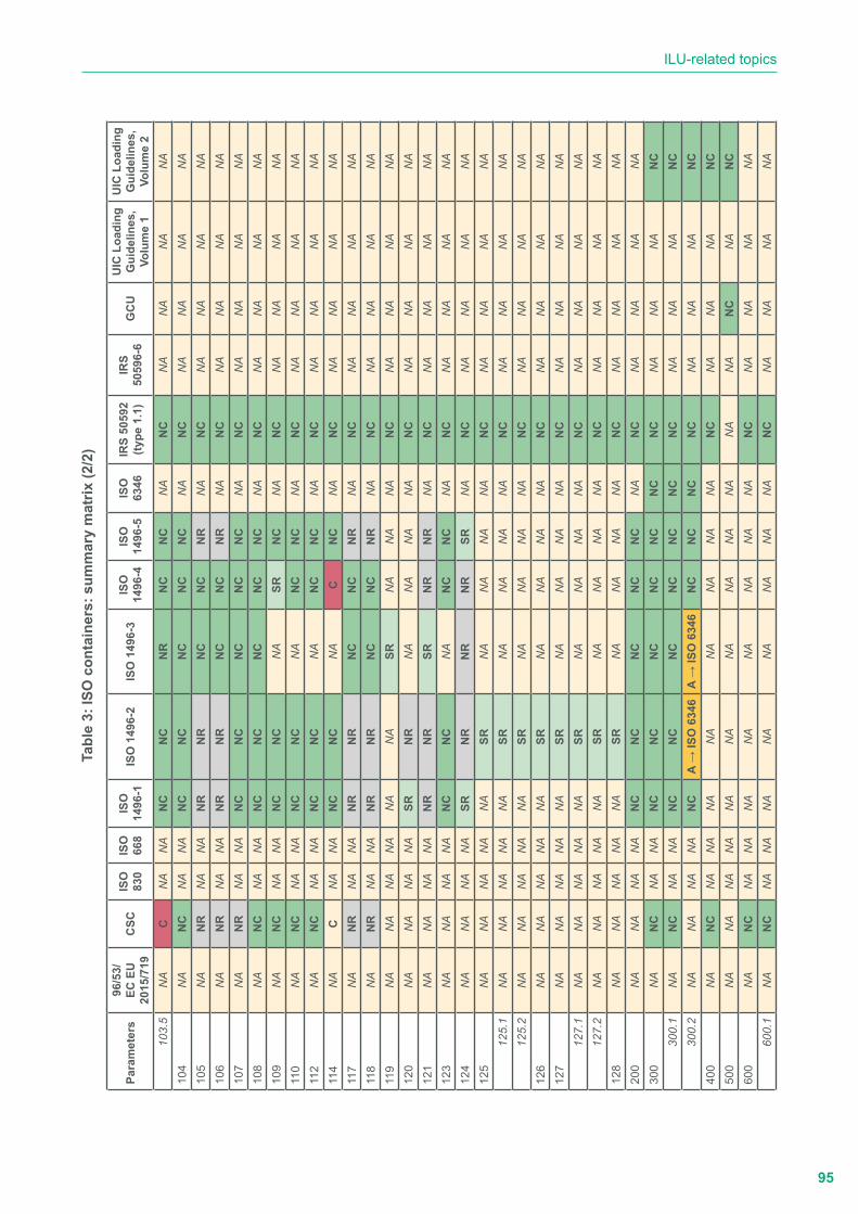
95
ILU-related topics
Tabl
e 3:
ISO
con
tain
ers:
sum
mar
y m
atrix
(2/2
)
Para
met
ers
96/5
3/EC
EU
20
15/7
19C
SCIS
O
830
ISO
66
8IS
O
1496
-1IS
O 1
496-
2IS
O 1
496-
3IS
O
1496
-4IS
O
1496
-5IS
O
6346
IRS
5059
2 (ty
pe 1
.1)
IRS
5059
6-6
GC
UU
IC L
oadi
ng
Gui
delin
es,
Volu
me
1
UIC
Loa
ding
G
uide
lines
, Vo
lum
e 2
103.
5N
AC
NA
NA
NC
NC
NR
NC
NC
NA
NC
NA
NA
NA
NA
104
NA
NC
NA
NA
NC
NC
NC
NC
NC
NA
NC
NA
NA
NA
NA
105
NA
NR
NA
NA
NR
NR
NC
NC
NR
NA
NC
NA
NA
NA
NA
106
NA
NR
NA
NA
NR
NR
NC
NC
NR
NA
NC
NA
NA
NA
NA
107
NA
NR
NA
NA
NC
NC
NC
NC
NC
NA
NC
NA
NA
NA
NA
108
NA
NC
NA
NA
NC
NC
NC
NC
NC
NA
NC
NA
NA
NA
NA
109
NA
NC
NA
NA
NC
NC
NA
SRN
CN
AN
CN
AN
AN
AN
A11
0N
AN
CN
AN
AN
CN
CN
AN
CN
CN
AN
CN
AN
AN
AN
A11
2N
AN
CN
AN
AN
CN
CN
AN
CN
CN
AN
CN
AN
AN
AN
A11
4N
AC
NA
NA
NC
NC
NA
CN
CN
AN
CN
AN
AN
AN
A11
7N
AN
RN
AN
AN
RN
RN
CN
CN
RN
AN
CN
AN
AN
AN
A11
8N
AN
RN
AN
AN
RN
RN
CN
CN
RN
AN
CN
AN
AN
AN
A11
9N
AN
AN
AN
AN
AN
ASR
NA
NA
NA
NC
NA
NA
NA
NA
120
NA
NA
NA
NA
SRN
RN
AN
AN
AN
AN
CN
AN
AN
AN
A12
1N
AN
AN
AN
AN
RN
RSR
NR
NR
NA
NC
NA
NA
NA
NA
123
NA
NA
NA
NA
NC
NC
NA
NC
NC
NA
NC
NA
NA
NA
NA
124
NA
NA
NA
NA
SRN
RN
RN
RSR
NA
NC
NA
NA
NA
NA
125
NA
NA
NA
NA
NA
SRN
AN
AN
AN
AN
CN
AN
AN
AN
A12
5.1
NA
NA
NA
NA
NA
SRN
AN
AN
AN
AN
CN
AN
AN
AN
A12
5.2
NA
NA
NA
NA
NA
SRN
AN
AN
AN
AN
CN
AN
AN
AN
A12
6N
AN
AN
AN
AN
ASR
NA
NA
NA
NA
NC
NA
NA
NA
NA
127
NA
NA
NA
NA
NA
SRN
AN
AN
AN
AN
CN
AN
AN
AN
A12
7.1
NA
NA
NA
NA
NA
SRN
AN
AN
AN
AN
CN
AN
AN
AN
A12
7.2
NA
NA
NA
NA
NA
SRN
AN
AN
AN
AN
CN
AN
AN
AN
A12
8N
AN
AN
AN
AN
ASR
NA
NA
NA
NA
NC
NA
NA
NA
NA
200
NA
NA
NA
NA
NC
NC
NC
NC
NC
NA
NC
NA
NA
NA
NA
300
NA
NC
NA
NA
NC
NC
NC
NC
NC
NC
NC
NA
NA
NA
NC
300.
1N
AN
CN
AN
AN
CN
CN
CN
CN
CN
CN
CN
AN
AN
AN
C30
0.2
NA
NA
NA
NA
NC
A →
ISO
634
6A
→ IS
O 6
346
NC
NC
NC
NC
NA
NA
NA
NC
400
NA
NC
NA
NA
NA
NA
NA
NA
NA
NA
NC
NA
NA
NA
NC
500
NA
NA
NA
NA
NA
NA
NA
NA
NA
NA
NA
NA
NC
NA
NC
600
NA
NC
NA
NA
NA
NA
NA
NA
NA
NA
NC
NA
NA
NA
NA
600.
1N
AN
CN
AN
AN
AN
AN
AN
AN
AN
AN
CN
AN
AN
AN
A
96
Comparative analysis of the combined transport usages and standards (CACTUS) - Final Report
b.2. Summary of the findings of the performed analysis
The requirements to be applied to containers to ensure their suitability for international exchange and for conveyance by road, rail and sea, including interchanges between these forms of transport, are provided by a complete set of ISO standards.
CSC provides regulations for the testing, inspection, approval and maintenance of containers in order to:
� maintain a high level of safety during their transport and handling; and
� facilitate the international transport of containers by providing uniform international safety regulations, equally applicable to all modes of transport.
UIC IRSs and Loading Guidelines provide requirements and best practices to ensure the conveyance of ISO containers by rail without hindrance.
Within this framework, IRS 50592, IRS 50596-6 and UIC Loading Guidelines, Volumes 1 & 2 refer to ISO-related standards and CSC, with no contradictions or overlap.
� Definitions (Parameter 1)
The definitions of ISO containers are out of the scope of Directive 96/53/EC and Directive (EU) 2015/719, IRS 50596-6, the GCU and UIC Loading Guidelines, Volumes 1 & 2.
No contradictions or overlaps in the relevant ISO standards.
ISO 830 provides definitions of terms relating to freight containers.
y Point 3: General terms and definitions
y Point 4: Container types
y Point 5: Terms and definitions related to container characteristics
y Point 6: Container components and structures
y Point 7: Terms and definitions applicable to certain types of containers
y Point 8: Definitions applicable to container handling and securing, visual identification and automatic identification
ISO 668 provides the following definitions:
y Point 3.1: Freight containers
y Point 3.2: ISO containers
y Point 3.3: Rating
y Point 3.4: Nominal dimension
y Point 3.5: Internal dimensions
y Point 3.6: Door opening
ISO 1496-1 and ISO 1496-3 refer to ISO 830.
Additional definitions for specific components and items are provided by:
y ISO 1496-2: Thermal containers;
y ISO 1496-4: Non-pressurized containers for dry bulk;
y ISO 1496-5: Platform and platform-based containers; and
y ISO 10374: Automatic identification of freight containers.
97
ILU-related topics
No definitions are provided by ISO 6346.
CSC provides, inter alia, the following definitions thus overlapping the same definitions provided by ISO 830:
y Container
y Corner fittings
y Rating (R)
y Maximum permissible Payload (P)
y Tare weight (T)
No definitions on containers and their related items are provided by IRS 50592.
� Classification (Parameter 2)
The classification of ISO containers is out of the scope of Directive 96/53/EC and Directive (EU) 2015/719, CSC, IRS 50596-6, the GCU and UIC Loading Guidelines, Volumes 1 & 2.
In accordance with ISO 830, container types are grouped, and groups are subdivided according to the following concepts:
y Mode of transport
y Categories of cargo
y Physical characteristics of the container
The main classification is made in terms of the type of cargo for which a container is primarily intended:
a. General cargo containers
1. General purpose containers
2. Specific purpose containers:
• closed ventilated containers
• open top containers
• platform (containers)
• platform-based containers:
• with incomplete superstructure and fixed ends
• with incomplete superstructure and folding ends
• with complete superstructure
b. Specific cargo containers
1. Thermal containers:
• insulated containers
• mechanically refrigerated containers
• refrigerated and heated containers
Thermal containers are also classified based on their ability to maintain a temperature under stated conditions (W/K, maximum allowable new thermal container heat-leakage rate).
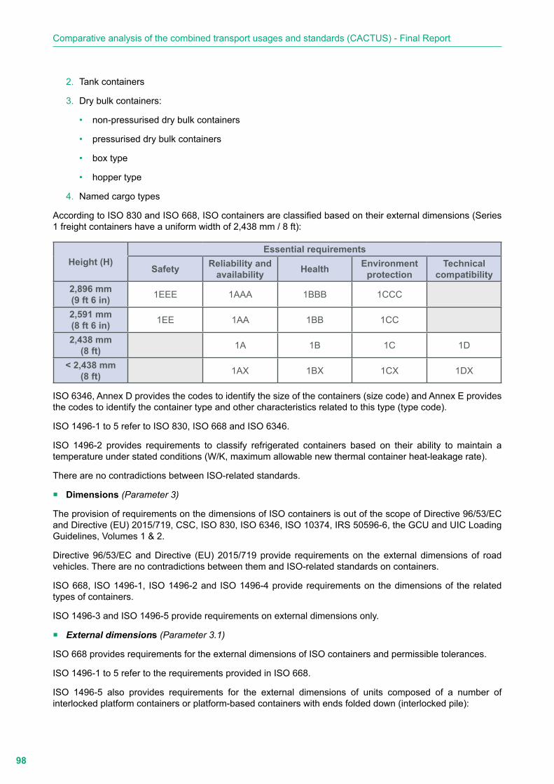
98
Comparative analysis of the combined transport usages and standards (CACTUS) - Final Report
2. Tank containers
3. Dry bulk containers:
• non-pressurised dry bulk containers
• pressurised dry bulk containers
• box type
• hopper type
4. Named cargo types
According to ISO 830 and ISO 668, ISO containers are classified based on their external dimensions (Series 1 freight containers have a uniform width of 2,438 mm / 8 ft):
Height (H)Essential requirements
Safety Reliability and availability Health Environment
protectionTechnical
compatibility2,896 mm(9 ft 6 in) 1EEE 1AAA 1BBB 1CCC
2,591 mm(8 ft 6 in) 1EE 1AA 1BB 1CC
2,438 mm(8 ft) 1A 1B 1C 1D
˂ 2,438 mm(8 ft) 1AX 1BX 1CX 1DX
ISO 6346, Annex D provides the codes to identify the size of the containers (size code) and Annex E provides the codes to identify the container type and other characteristics related to this type (type code).
ISO 1496-1 to 5 refer to ISO 830, ISO 668 and ISO 6346.
ISO 1496-2 provides requirements to classify refrigerated containers based on their ability to maintain a temperature under stated conditions (W/K, maximum allowable new thermal container heat-leakage rate).
There are no contradictions between ISO-related standards.
� Dimensions (Parameter 3)
The provision of requirements on the dimensions of ISO containers is out of the scope of Directive 96/53/EC and Directive (EU) 2015/719, CSC, ISO 830, ISO 6346, ISO 10374, IRS 50596-6, the GCU and UIC Loading Guidelines, Volumes 1 & 2.
Directive 96/53/EC and Directive (EU) 2015/719 provide requirements on the external dimensions of road vehicles. There are no contradictions between them and ISO-related standards on containers.
ISO 668, ISO 1496-1, ISO 1496-2 and ISO 1496-4 provide requirements on the dimensions of the related types of containers.
ISO 1496-3 and ISO 1496-5 provide requirements on external dimensions only.
� External dimensions (Parameter 3.1)
ISO 668 provides requirements for the external dimensions of ISO containers and permissible tolerances.
ISO 1496-1 to 5 refer to the requirements provided in ISO 668.
ISO 1496-5 also provides requirements for the external dimensions of units composed of a number of interlocked platform containers or platform-based containers with ends folded down (interlocked pile):

99
ILU-related topics
y Plan dimensions as specified in ISO 668
y Pile height not exceeding 2,896 mm
� Internal dimensions (Parameter 3.2)
ISO 668 provides requirements for minimum internal dimensions and door openings dimensions. ISO 1496-1, ISO 1496-2 and ISO 1496-4 refer to the requirements provided in ISO 668.
� Ratings (Parameter 4)
The provision of requirements on ISO containers ratings is out of the scope of Directive 96/53/EC, Directive (EU) 2015/719, CSC, ISO 830, ISO 6346, ISO 10374, IRS 50596-6, the GCU and UIC Loading Guidelines, Volumes 1 & 2.
Directive 96/53/EC and Directive (EU) 2015/719 provide requirements on the maximum permitted masses of road vehicles. There are no contradictions between them and ISO-related standards on containers.
ISO 668 provides requirements for the maximum gross mass of containers. ISO 1496-1 to 5 refer to the requirements provided in ISO 668.
� Load transfer areas (Parameter 5)
The provision of requirements on load transfer areas is out of the scope of Directive 96/53/EC, Directive (EU) 2015/709, CSC, ISO 830, ISO 6346, ISO 10374, IRS 50596-6, the GCU and UIC Loading Guidelines, Volumes 1 & 2.
ISO 668 and ISO 1496-1 to 5 provide, with no contradictions or overlap, the requirements on the dimensions and position of load transfer areas for the relevant types of containers:
y ISO 668, Appendix B provides the requirements for load transfer areas:
• Minimum number (Point B.2.2)
• Position (Point B.2.3)
• Dimensions (Point B.2.4).
y ISO 1496-1, Point 5.3.2 and Annex B provide additional requirements to those provided in ISO 668.
y ISO 1496-2, Point 7.3.2 and Annex B provide additional requirements to those provided in ISO 668.
y ISO 1496-3: load transfer areas are optional; Point 5.3.2 provides additional requirements to those provided in ISO 668.
y ISO 1496-4: load transfer areas are optional; Point 5.3.2 and Annex B provide additional requirements to those provided in ISO 668.
y ISO 1496-5, Point 5.3.2 and Annex B provide additional requirements to those provided in ISO 668.
� Gooseneck tunnel/steering tunnel: dimensions and location (Parameter 7)
The provision of requirements on gooseneck tunnels is out of the scope of Directive 96/53/EC, Directive (EU) 2015/709, CSC, ISO 830, ISO 6346, ISO 10374, IRS 50596-6, the GCU and UIC Loading Guidelines, Volumes 1 & 2.
ISO 668 and ISO 1496-1 to 4 provide, with no contradictions or overlap, the requirements on the dimensions and position of gooseneck tunnels for the relevant types of containers:
ISO 668, Point 5.2.3: equipping containers with a gooseneck tunnel is:
y mandatory for 1EEE and 1AA, and
y optional for 1EE, 1AA, 1A and 1AX.

100
Comparative analysis of the combined transport usages and standards (CACTUS) - Final Report
Space required according to Appendix C, Figure C.1. Dimensions according to Appendix C, Table C.1.
y ISO 1496-1: no additional requirements to those provided in ISO 668.
y ISO 1496-2, Point 7.9.2: mandatory for 1AAA and optional for 1AA, 1A, 1BB and 1B; space and dimensions compliant with ISO 668.
y ISO 1496-3, Point 5.7.1: mandatory for 1AAA and optional for 1AA and 1A; space and dimensions compliant with ISO 668.
y ISO 1496-4, Point 5.10.3: mandatory for 1AAA and optional for 1AA and 1A; space and dimensions compliant with Annex E.
ISO 1496-5 does not provide any requirements.
� Upper and bottom fittings (Parameter 8)
Requirements on the location and technical characteristics of upper and bottom corner fittings are out of the scope of Directive 96/53/EC, Directive (EU) 2015/709, CSC, ISO 830, ISO 6346, ISO 10374, IRS 50596-6, the GCU and UIC Loading Guidelines, Volumes 1 & 2.
Requirements on the location and technical characteristics of upper and bottom corner fittings are provided in ISO 668 and ISO 1496-1 to 5.
� Upper (corner/intermediate) fittings: dimensions and location (Parameter 8.1)
� Bottom (corner/intermediate) fittings: dimensions and location (Parameter 8.2)
ISO 668, Appendix A, Figure A.1 and Table A.1 provide requirements for the location of corner fittings, the location of top (upper) and bottom corner fittings, and centre to centre distances:
y 1EEE and 1EE = 13,509 mm
y 1AAA, 1AA, 1A and 1AX = 11,985 mm
y 1BBB, 1BB, 1B and 1BX = 8,518 mm
y 1CCC, 1CC, 1C and 1CX = 5,853 mm
y 1D and 1DX = 2,787 mm
Equipping ISO containers with upper (top) and bottom corner fittings is a mandatory requirement provided by ISO 1496-1 to 5. Their location is defined in ISO 668, Appendix A (Figure A.1 and Table A.1).
Point 5.2: all general cargo containers for general purposes shall be equipped with top and bottom corner fittings; 1EEE and 1EE units shall also have intermediate fittings in the 1 AAA/1 AA/1 A position.
� Technical requirements (Parameter 8.3)
According to ISO 668 and ISO 1496-1 to 5, the upper and bottom corner and intermediate fittings shall be compliant with ISO 1661.
� Grappler arm grooves: dimensions and location (Parameter 9)
In accordance with ISO 1496-4, Point 5.10.2, equipping non-pressurised containers for dry bulk with grappler arm grooves is optional. Annex D provides requirements on the location and dimensions of grappler arm grooves.
No requirements are provided in ISO 668, ISO 1496-1, ISO 1496-2, ISO 1496-3 and ISO 1496-5.
Requirements on the location and dimensions of grappler arm grooves are out of the scope of Directive 96/53/EC, Directive (EU) 2015/709, CSC, ISO 830, ISO 6346, ISO 10374, IRS 50596-6, the GCU and UIC Loading Guidelines, Volumes 1 & 2.
101
ILU-related topics
� Fork-lift pockets: dimensions and location (Parameter 11)
Equipping the following types of containers with fork-lift pockets is prohibited:
y ISO 1496-1: 1EEE, 1EE, 1AAA, 1AA, 1AX, 1BBB, 1BB, 1B and 1BX
y ISO 1496-3: all types
y ISO 1496-4: 1AAA, 1AA, 1AX, 1BBB, 1BB, 1B and 1BX
Equipping other types of containers with fork-lift pockets is optional. ISO 1496-1, ISO 1496-2, ISO 1496-4 and ISO 1496-5 provide requirements on the dimensions and location of fork-lift pockets when designed for handling by fork-lifts.
y Loaded and empty:
• ISO 1496-1: 1CC, 1C, 1CX, 1D and 1DX
• ISO 1496-2: 1CC, 1C and 1D
• ISO 1496-3: 1CC, 1C, 1CX, 1D and 1DX
y Only empty:
• ISO 1496-2: 1AAA, 1AA, 1A, 1BBB, 1BB and 1B
• ISO 1496-5: 1AAA, 1AA, 1A, 1AX, 1BBB, 1BB, 1B and 1BX
Providing a second set of fork-lift pockets for empty handling only is permitted in accordance with:
y ISO 1496-1: 1 CC, 1C and 1 CX
y ISO 1496-2: 1CC and 1C
y ISO 1496-4: 1 CC, 1C and 1 CX
y ISO 1496-5: 1AAA, 1AA, 1A, 1AX, 1BBB, 1BB, 1B and 1BX
Requirements on the location and dimensions of fork-lift pockets are out of the scope of Directive 96/53/EC, Directive (EU) 2015/709, CSC, ISO 830, ISO 6346, ISO 668, ISO 10374, IRS 50596-6, the GCU and UIC Loading Guidelines, Volumes 1 & 2.
� Slinging apertures: dimensions and location (Parameter 12)
Requirements on the location and dimensions of slinging apertures are out of the scope of Directive 96/53/EC, Directive (EU) 2015/709, CSC, ISO 830, ISO 6346, ISO 10374, IRS 50596-6, the GCU and UIC Loading Guidelines, Volumes 1 & 2.
In accordance with ISO 668, slinging apertures are integrated into the bottom fittings. ISO 1496-1 to 5 do not provide any additional requirements.
� Body structure (Parameter 19)
Requirements on ISO container body structure are out of the scope of Directive 96/53/EC, Directive (EU) 2015/709, CSC, ISO 830, ISO 6346, ISO 668, ISO 10374, IRS 50596-6, the GCU and UIC Loading Guidelines, Volumes 1 & 2.
ISO 1496-1 to 5 provide design requirements for the body structure of containers in accordance with the requirements provided by ISO 668 for load transfer areas (see Parameter 5).
Common requirements that are sometimes integrated by specific clauses related to container types are provided for:
y base structure,
102
Comparative analysis of the combined transport usages and standards (CACTUS) - Final Report
y end structure, and
y side structure.
In addition, dedicated requirements for the design of components of the different container types are provided by:
y 1496-1:
• Door openings
y 1496-2:
• Walls
• Door openings
• Sanitary and taint free requirements
• Openings in one end of a thermal container to accommodate an integral refrigeration unit (picture frame)
y 1496-4:
• Walls (box type)
• Shell (hopper type)
• Door openings
• Openings for loading
• Openings for discharging
• Inspection and maintenance openings
y 1496-5:
• Walls
� Ladders (Parameter 21)
Requirements on ladders are out of the scope of Directive 96/53/EC, Directive (EU) 2015/709, CSC, ISO 830, ISO 6346, ISO 668, ISO 10374, IRS 50596-6, the GCU and UIC Loading Guidelines, Volumes 1 & 2.
In accordance with ISO 1496-3 and ISO 1496-4 the equipment of tank containers and non-pressurised containers for dry bulk with ladders is optional. ISO 1496-3, Point 5.7.3 and ISO 1496-4, Point 5.10.5 provide mandatory requirements for the design of ladders.
No requirements on ladders are provided in ISO 1496-1, ISO 1496-2 and ISO 1496-5.
� Walkways (Parameter 22)
Requirements on walkways are out of the scope of Directive 96/53/EC, Directive (EU) 2015/709, CSC, ISO 830, ISO 6346, ISO 668, ISO 10374, IRS 50596-6, the GCU and UIC Loading Guidelines, Volumes 1 & 2.
In accordance with ISO 1496-3 and ISO 1496-4 the equipment of tank containers and non-pressurised containers for dry bulk with walkways is optional. ISO 1496-3, Point 5.7.2 and ISO 1496-4, Point 5.10.4 provide mandatory requirements for the design of walkways.
No requirements on walkways are provided in ISO 1496-1, ISO 1496-2 and ISO 1496- 5.
� Cargo securing (Parameter 24)
Requirements on cargo securing systems are out of the scope of Directive 96/53/EC, Directive (EU) 2015/709, CSC, ISO 830, ISO 6346, ISO 668, ISO 1496-3, ISO 1496-4, ISO 10374, IRS 50596-6,the GCU and UIC Loading Guidelines, Volumes 1 & 2.

103
ILU-related topics
Cargo securing systems are designed to restrain the movement of cargo caused by dynamic forces induced during transportation. They consist of:
y cargo securing devices,
y shoring, or
y a combination of the above.
� Anchor and lashing points (Parameter 24.1)
Cargo securing devices are permanent fixtures to which lashings (such as ropes, straps, chains, cables, etc.) may be attached. Such devices are not intended for any other purpose, for example, handling or securing containers. They are either fixed, hinged or sliding eyes, rings or bars.
Two types of cargo securing devices are considered by ISO 1496-1 and 1496-5:
y Anchor points
y Shoring slots
Anchor points are securing devices located in the base structure of the container.
Lashing points are securing devices located in any part of the container other than their base structure.
Equipping all series 1 general purpose containers with anchor points and lashing points for cargo securing is optional for all series 1 general purpose containers and mandatory for:
y containers provided with end walls which are not able to withstand the relevant strength tests; and
y containers which have no side walls.
ISO 1496-1, Annex C and ISO 1496-5, Annex C provide mandatory requirements for anchor points and lashing points.
ISO 1496-2 does not provide requirements on anchor points and lashing points.
Tank containers compliant with ISO 1496-3 and non-pressurised containers for dry bulk compliant with ISO 1496-4 are not equipped with anchor points and lashing points.
� Shoring slots (Parameter 24.2)
The shoring slot is a permanent fixture into which cargo securing bars or boards can be inserted.
Shoring slot systems are designed to restrain the cargo from forcing the door open during sudden stops or tilts of the container during transportation. They consist of shoring slots and one or more cargo securing bars.
Shoring slots are optional features in all series 1 general purpose containers. ISO 1496-2 and ISO 1496-5 do not provide requirements on shoring slots.
Tank containers compliant with ISO 1496-3 and non-pressurised containers for dry bulk compliant with ISO 1496-4 are not equipped with shoring slots.
� Refrigeration/heating unit (Parameter 27)
ISO 1496-2 does not provide requirements on the technical characteristics of refrigeration/heating units but provides requirements for their mechanical interfacing with the body structure of the thermal container and an example of installation (Point 9.5.2, Annexes B and F).
Requirements on refrigeration/heating units are out of the scope of the remaining relevant reference documentation.

104
Comparative analysis of the combined transport usages and standards (CACTUS) - Final Report
Thermal characteristics of the isothermal body (Parameter 28)
In contrast to what is required for thermal swap bodies, the thermal characteristics of ISO thermal containers are not defined in conformity with the ATP convention.
In accordance with ISO 1496-2, thermal containers shall be able to withstand the following performance tests specified in Chapter 8 in which the related limit values are defined:
y Airtightness (Point 8.2.3)
y Heat leakage (Point 8.3.4)
y Performance of a thermal container under refrigeration by a mechanical refrigeration unit (Point 8.4.4)
y Performance of a thermal container at high ambient temperatures while being cooled by a mechanical refrigeration unit (Point 8.5.5)
y Energy consumption of a thermal container at defined ambient temperatures while being cooled by a mechanical refrigeration unit (Point 8.6.5)
Requirements on thermal characteristics are out of the scope of the remaining relevant reference documentation.
� Tank characteristics (Parameter 30)
EN 1496-2 provides:
y Mandatory requirements for:
• Design and construction (Point 5.6.1)
• Corrosion allowance (Point 5.6,2)
• Tank openings (Point 5.6.3)
• Pressure and vacuum relief devices (Point 5.6.4)
• Opening for inspection, cleaning and maintenance (Point 5.6.5)
• Gauging devices (Point 5.6.6)
• Sealings (Point 5.6.7)
y Optional requirements for:
• Insulation (Point 5.7.4)
• Heating and refrigeration (Point 5.7.5)
Requirements on the characteristics of tanks installed on tank containers are out of the scope of the remaining relevant reference documentation.
� Electrical aspects (Parameter 31)
The following requirements provided by ISO 1496-2 are only intended to govern those aspects of electrically powered thermal containers that affect interchange or are the minimum needed to affect safety. They do not constitute a detailed electrical specification.
Point 9.2 provides general requirements for standard voltage equipment and the following:
y In Annex D, requirements for wiring plugs and sockets for standard voltage equipment.
y In Annex E, requirements for electric plug and socket, four-pin, 380 V/440 V, 50 Hz/60 Hz, 32 A.
y In Annex F, information concerning electrical power supplies for thermal containers.

105
ILU-related topics
y In Annex G, general requirements for 220 V and dual voltage equipment. Point 9.3 provides optional requirements for remote condition monitoring.
The electrical aspects of ISO containers are out of the scope of the remaining relevant reference documentation.
� Interlocked pile of folded containers (Parameter 32)
Interlocked piles are units composed of number of interlocked platform containers or platform-based containers with ends folded down.
ISO 1496-5, Point 5.2 provides requirements for the design of interlocked piles of either platform or folded platform-based containers:
y Dimensions: horizontal free play shall be limited between individual folded containers forming an interlocked pile, so that the pile complies with the dimensional requirements of 2,896 mm.
y Ratings: the sum of the tare masses of the platform containers forming an interlocked pile, together with any required securing devices, shall not exceed the maximum gross mass (MGM) specified in ISO 668 for the container size in question.
� Tests (Parameter 100)
In order to maintain a high level of safety when transporting and handling containers and to facilitate the international transport of containers by providing uniform international safety regulations, equally applicable to all modes of surface transport, CSC provides a set of test procedures and related strength requirements which represent a combination of safety requirements for both inland and maritime modes of transport.
ISO 1496-1 to 5 provide test requirements that are intended to demonstrate the capability of the related types of containers to withstand, without failures of any kind during their service life, the loads encountered under the dynamic and normal operating conditions of various forms of intermodal transport.
They are also intended to simulate the dynamic stresses exerted on the related types of containers during the various modes of transportation employed in use and, for reasons of reproducibility and ease of handling, all tests, except internal restraint tests on tank containers, are carried out when static.
� General (Parameter 101)
Test requirements on containers are out of the scope of Directive 96/53/EC, Directive (EU) 2015/709, ISO 830, ISO 6346, ISO 668, ISO 10374, IRS 50596-6, the GCU and UIC Loading Guidelines,
Volumes 1 & 2.
IRS 50592 refers to ISO 1496-1 to 5 test requirements.
The following tests are considered in both CSC and ISO 1496-1:
y Stacking
y Lifting from the grappler arm grooves
y Liftings from four upper corner fittings
y Lifting from four bottom corner fittings
y Lifting from the slinging apertures
y Lifting from fork-lift pockets
y External restraint (longitudinal)
y Rigidity (transversal)
y Strength of end walls

106
Comparative analysis of the combined transport usages and standards (CACTUS) - Final Report
y Strength of side walls
y Strength of the roof
y Floor strength
� Stacking (Parameter 102)
CSC and ISO 1496-1 to 5 provide requirements for testing the ability of fully loaded containers to support a superimposed mass of containers, considering conditions aboard ships at sea and the relative eccentricities between superimposed containers.
In all the above-mentioned documents, the formula set up to define the value of the force to be applied in stacking tests is the same (all four corners simultaneously).
Force = (1.8g x MAS) [kN]
where MAS is the value of the allowable superimposed stacking mass [kg].
The MAS value differs depending on the related documents:
y ISO 1496-1 to 5: MAS = (30,240 X 7) kg corresponding to a superimposed mass of 8-high stacking, i.e. 7 fully loaded containers stacked on top of one container (all being rated to 30,480 kg).
y CSC: the MAS value is indicated in the Safety Approval Plate and may correspond to the mass of a lower number of superimposed containers.
ISO 1496-5, Point 7.2 provides, with no contradictions, specific requirements for tests to be carried out to prove the ability of a folding container when folded.
� Lifting (Parameter 103)
CSC and ISO 1496-1 to 5 provide requirements for testing the ability of a container, whether loaded or empty, to withstand being lifted vertically using the upper and bottom fittings, grappler arm grooves, slinging apertures or fork-lifts.
� Lifting from the grappler arm grooves (Parameter 103.1)
CSC and ISO 1496-4 provide, without contradiction, requirements for testing the ability of containers to be lifted from grappler arm grooves:
y Combined mass of container + test load (uniformly distributed) = 1.25 R for at least 5 minutes
ISO 1496-1, ISO 1496-2, ISO 1496-3 and ISO 1496-5 do not provide requirements for testing the ability of the related containers to be lifted with grappler arm grooves.
� Lifting from the four upper fittings (Parameter 103.2)
CSC and ISO 1496-1 to 5 provide, without contradiction, requirements for testing the ability of containers to be lifted from their four upper fittings:
y Combined mass of container + test load = 2.0 R for at least 5 minutes
y Lifting forces applied vertically
y Only for 1D and 1DX, angle between each lifting device and the horizontal: α = 60°
ISO 1496-5, Point 7.3 provides specific requirements for tests to be carried out to prove the resistance of either a platform or a folded container connected to an interlocked pile when lifted from above with the lifting forces applied vertically.
� Lifting from the four bottom fittings (Parameter 103.3)

107
ILU-related topics
CSC and ISO 1496-1 to 5 provide, without contradiction, requirements for testing the ability of containers to be lifted from their four bottom fittings:
y Combined mass of container + test load = 2.0 R for at least 5 minutes
y Depending on the container length:
1EEE, 1EE, 1AAA, 1AA and 1A → α = 30°
1BBB, 1BB,1B and 1BX → α = 37°
1CC, 1C and 1CX → α = 45°
1D and 1DX → α = 60°
Where α is the angle between the direction of the lifting force and the horizontal.
� Lifting from the slinging apertures (Parameter 103.4)
As per Parameter 103.3.
� Lifting from fork-lift pockets (Parameter 103.5)
CSC, ISO 1496-1, ISO 1496-2 and ISO 1496-4 provide requirements for this parameter. In contradiction with CSC, ISO 1496-1, ISO 1496-2 and ISO 1496-4 set the combined mass of the swap body and the test load to 1.60 R instead of 1.25 R.
In accordance with ISO 1496-3, tank swap bodies are not equipped with fork-lift pockets.
� External restraint (longitudinal) (Parameter 104)
CSC and ISO 1496-1 to 5 provide requirements for static tests to be performed to prove an ILU’s ability to withstand longitudinal external restraint under the dynamic conditions of railway operation:
y Combined mass of container + test load (uniformly distributed) = 1.0 R
y Applied longitudinal force = 2.0 Rg on the base of the container for at least 5 minutes
� Internal restraint (longitudinal) (Parameter 105)
ISO 1496-3 and ISO 1496-4 (only for hopper containers) provide requirements for tests to be performed to prove a container’s ability to withstand longitudinal internal restraint under the dynamic conditions of railway operation.
y Combined mass of container + test load = 1.0 R
y Longitudinal acceleration = - 2 g
Dynamic tests are performed on a dedicated test platform according to the procedure specified in ISO 1496, Annex B.
� Internal restraint (lateral) (Parameter 106)
ISO 1496-3 and ISO 1496-4 (only for hopper containers) provide requirements for static tests to be performed to prove a tank container’s ability to withstand lateral internal restraint under the dynamic conditions of transport:
y Combined mass of container + test load = 1.0 R
y Tank container positioned for at least 5 minutes with its transverse axis vertical
This type of test is not required by CSC.
� Rigidity (longitudinal) (Parameter 107)

108
Comparative analysis of the combined transport usages and standards (CACTUS) - Final Report
ISO 1496-1 to 5 provide requirements for static tests to be performed to prove a container’s ability to withstand longitudinal racking forces resulting from ship movement:
y Combined mass of container + test load = T (empty container)
y Force of 75 kN applied to each of the top corner fittings on one end of the container in lines parallel both to the base of the container and to the planes of the sides of the container (first towards and then away from the top corner fitting)
� Rigidity (transverse) (Parameter 108)
CSC and ISO 1496-1 to 5 provide requirements for static tests to be performed to prove a container’s ability to withstand longitudinal racking forces resulting from ship movement:
y Combined mass of container + test load = T (empty container)
y Force of 75 kN applied to each of the top corner fittings on one side of the container in lines parallel both to the base of the container and to the planes of the sides of the container (first towards and then away from the top corner fitting)
� Strength of end walls (Parameter 109)
CSC, ISO 1496-1, 1496-2, ISO 1496-4 and ISO 1496-5 provide requirements for tests to be performed to prove a container’s ability to withstand the forces caused by the cargo under the dynamic conditions of railway operations:
y ISO 1496-1, ISO 1496-2, and ISO 1496-5: Test force = 0.4 Pg uniformly distributed for at least 5 minutes
y ISO 1496-4:
• 1AAA, 1AA, 1A, 1AX, 1BB, 1B and 1BX: Test force = 0.4 Pg uniformly distributed for at least 5 minutes
• 1CCC, 1CC, 1C and 1CX: Test force = 0.4 Pg uniformly distributed for at least 5 minutes
In accordance with CSC, if test force ≠ 0.4 Pg, this shall be indicated in the Safety Approval Plate.
� Strength of side walls (Parameter 110)
CSC, ISO 1496-1, ISO 1496-2 and ISO 1496-4 provide requirements for tests to be performed to prove a container’s ability to withstand the forces caused by the cargo under the dynamic conditions of ship operations:
y Test force = 0.6 Pg uniformly distributed for at least 5 minutes
In accordance with CSC, if test force ≠ 0.6 Pg, this shall be indicated in the Safety Approval Plate.
� Strength of the roof (Parameter 112)
CSC, ISO 1496-1, ISO 1496-2, ISO 1496-4 and ISO 1496-5 provide requirements for tests to be performed to prove the ability of the rigid roof of a container to withstand the forces caused by the loads imposed by persons working on the roof:
y Test load = 300 kg uniformly distributed on an area of 600 mm x 300 mm for 5 minutes
� Floor strength (Parameter 114)
CSC, ISO 1496-1, ISO 1496-2 and ISO 1496-4 provide requirements for tests to be performed to prove the ability of a container floor to withstand concentrated dynamic loading during cargo operations involving trucks or similar devices. CSC and ISO standards provide different requirements:
y CSC and ISO 1496-4: Two concentrated loads of 2,730 kg applied through a contact area of 142 cm2
(width = 180 mm and spaced 760 mm apart, centre to centre)
y ISO 1496-1, ISO 1496-2 and ISO 1496-5: Two concentrated loads of 3,630 kg applied through a contact area of 142 cm2 (width = 180 mm and spaced 760 mm apart, centre to centre)
109
ILU-related topics
� Testing ladders (Parameter 117)
ISO 1496-3 and ISO 1496-4 provide requirements for tests to be performed to prove the ability of the ladder equipping a tank container or non-pressurised container for dry bulk to withstand the loads imposed by persons working thereon:
y Test load = 200 kg at the centre of the widest rung
� Testing walkways (Parameter 118)
ISO 1496-3 and ISO 1496-4 provide requirements for tests to be performed to prove the ability of the walkways equipping a tank container or non-pressurised container for dry bulk to withstand the loads imposed by persons working thereon:
y Test load = 300 kg uniformly distributed on an area of 600 mm x 300 mm for 5 minutes
� Pressure tests (Parameter 119)
ISO 1496-3 provides requirements for pressure tests to be carried out on every tank container to prove the ability of the tank to withstand the specified internal pressure. In accordance with Point 6.13.2, the tank shall be hydraulically tested.
Pressure test requirements are out of the scope of CSC, ISO 1496-1, ISO 1496-2, ISO 1496-4 and ISO 1496-5.
� Testing shoring slots (Parameter 120)
ISO 1496-1 provides requirements for tests to be performed to prove the ability of the shoring slots to withstand the loads caused by the cargo, while it is restrained, from forcing the door open during sudden stops or tilts of the container during transportation:
y Test force = 0.6 Pg for at least 2 minutes
Test requirements on shoring slots are out of the scope of CSC, ISO 1496-3, ISO 1496-4 and ISO 1496-5.
ISO 1496-2 does not provide any test requirements on shoring slots.
� Testing load transfer areas (Parameter 121)
ISO 1496-3 provides requirements for tests to be performed to prove the ability of a tank container to avoid leakage, permanent deformation or abnormality which would render it unsuitable for use. Additionally, the dimensional requirements affecting handling, securing and interchange shall be satisfied.
y Combined mass of tank container + test load = 2 R for at least 5 minutes
No specific test requirements are provided in ISO 1496-1, ISO 1496-2, ISO 1496-4 and ISO 1496- 5.
Test requirements on load transfer areas are out of the scope of CSC.
� Weatherproofness (Parameter 123)
ISO 1496-1, ISO 1496-2, ISO 1496-4 and ISO 1496-5 provide, with no contradictions, requirements for tests to be performed to prove the ability of the related types of containers to remain watertight after a stream of water has been applied on all exterior joints and seams.
Requirements on this test are out of the scope of CSC and ISO 1496-3.
� Testing anchor and lashing points (Parameter 124)
ISO 1496-1 and ISO 1496-5 provide requirements for tests to be performed to prove the ability of the related types of containers to withstand the loads caused by the cargo while it is secured to prevent the movement resulting from dynamic forces induced during transportation.
y Tensile test force = 1.5 times the rated load

110
Comparative analysis of the combined transport usages and standards (CACTUS) - Final Report
y Rated loads:
• ISO 1496-1 = 1,000 kg for anchor points and 500 kg for lashing points, applied according to the procedure set up in Annex C
• ISO 1496-5 (platform-based containers) = 3,000 kg for anchor points and 1,000 kg for lashing points, applied according to the procedure set up in Annex C
No specific test requirement is provided in ISO 1496-2, ISO 1496-3 and ISO 1496-4. Test requirements on load transfer areas are out of the scope of CSC.
� Testing refrigeration/heating unit performance (Parameter 125)
ISO 1496-2 provides specific requirements for the following tests to be performed on refrigeration/heating units:
y Performance and function tests
y Energy consumption tests
Test requirements on refrigeration/heating unit performance are out of the scope of CSC, ISO 1496- 1, ISO 1496-3, ISO 1496-4 and ISO 1496-5.
� Performance and functional tests (Parameter 125.1)
Performance tests
ISO 1496-2, Point 8.4 provides requirements on performance tests of a thermal container under refrigeration by a mechanical refrigeration unit (MRU) to prove that it is able to maintain the average inside temperature of the thermal container at the specified level for a period of at least 8 h and then for a further period of at least 4 h with additional heat load equal to at least 35% of the total heat leakage rate for the containers, as determined in the heat leakage test (see Parameter 127.2).
Functional tests
ISO 1496-2, Point 8.5 provides requirements on functional tests of a thermal container at high ambient temperatures while being cooled by a mechanical refrigeration unit (MRU) to verify its unrestricted function.
� Energy consumption (Parameter 125.2)
ISO 1496-2, Point 8.6 provides requirements on energy consumption tests of a thermal container at defined ambient temperatures while being cooled by a mechanical refrigeration unit (MRU) to verify the energy consumption. The test shall be carried out with additional heat load to simulate metabolic activity where appropriate above that leaking through the walls of the container.
� Testing refrigeration/heating unit attachments (mounting devices) (Parameter 126)
ISO 1496-2, Point 8.7 provides requirements for tests to be carried out to prove the ability of the thermal container end frame to support loading in the vertical (Point 8.7.3) and horizontal (Point 8.7.3) directions due to the installed mass of the removable equipment, taking into account road and rail modes of transport.
Test requirements related to this parameter are out of the scope of CSC, ISO 1496-1, ISO 1496-3, ISO 1496-4 and ISO 1496-5.
� Testing thermal characteristics (Parameter 127)
ISO 1496-2 provides specific requirements for heat leakage tests and airtightness tests to be performed on thermal containers.
Test requirements on heat leakage and airtightness tests of thermal containers are out of the scope of CSC, ISO 1496-1, ISO 1496-3, ISO 1496-4 and ISO 1496-5.
ISO 1496-4 provides specific requirements for testing the airtightness of dry bulk non-pressurised containers (only box and hopper type). This is not a thermal requirement.

111
ILU-related topics
Test requirements related to this parameter are out of the scope of CSC, ISO 1496-1, ISO 1496-3, ISO 1496-4 and ISO 1496-5.
� Heat leakage tests (Parameter 127.1)
ISO 1496-2, Point 8.3 provides requirements for tests to be carried out to establish heat leakage for thermal containers.
It shall be carried out after successful completion of the airtightness tests (see Parameter 127.2). It shall be performed using the inner heating method only.
� Airtightness tests (Parameter 127.2)
ISO 1496-2, Point 8.2 provides requirements for tests to be carried out on thermal containers to prove that the air leakage rate, expressed in standard atmospheric conditions, shall not exceed 5 m3/h (an extra allowance of 5 m3/h is granted for each additional door opening provided).
This test shall be carried out after all structural tests have been completed and prior to the heat leakage test (see Parameter 127.1).
ISO 1496-4, Point 6.19 provides requirements for tests to be carried out on box-type and hopper- type containers to prove that the air leakage rate, expressed in standard atmospheric conditions, shall not exceed the limits provided in Point 6.19.3, Table 3 5.
This test shall be carried out after all structural tests have been completed.
� Design loadings (Parameter 200)
The basic parameters for the design of ILUs are:
y P = Maximum permissible payload
y R = Permissible total mass of the ILU
y T = Tare mass
The values of the test loads and forces to apply to ILUs and their components when tests are performed are defined in the requirements provided for the above-mentioned parameters by CSC and ISO 1496-1 to 5.
There are no contradictions between IRS 50592 and ISO standards.
� Identification and markings (Parameter 300)
Requirements on the identification and marking of ISO containers are out of the scope of Directive 96/53/EC, Directive (EU) 2015/709, ISO 830, ISO 668, IRS 50596-6, the GCU and UIC Loading Guidelines, Volume 1.
CSC, ISO 1496-1 to 5, ISO 6346 and UIC Loading Guidelines, Volume 2 provide requirements for the identification and marking of ILUs other than semi-trailers.
IRS 50592 refers to the requirements provided by ISO 6346.
UIC Loading Guidelines, Volume 2 provides the list of container markings, together with explanations of their purpose for operational staff.
� Identification (Parameter 300.1)
ISO 6346 provides:
y an identification system with mandatory marks for the presentation of the identification system for visual interpretation and features to be used in optional Automatic Equipment Identification and Electronic Data Interchanging; and
y a coding system for data on container size and type.
112
Comparative analysis of the combined transport usages and standards (CACTUS) - Final Report
The identification system consists of:
y owner code (3 letters),
y equipment category identifier (1 letter),
y serial number (6 numerals), and
y check digit (1 numeral).
The owner code shall be unique and shall be registered with BIC (Bureau International des Containers).
Requirements for the definition of the equipment category identifier, the serial number and the check digit are provided in Points 3.1.2 and 3.1.3 and Annex A.
The coding system consists of:
y size code (2 alphanumerical characters), and
y type code (2 characters).
Requirements for the definition of the size code are provided in Point 4.2.1 and Annex D; those for the definition of the type code, in Point 4.2.2 and Annex E.
ISO 1496-4 to1496-5 and IRS 30592 refer to ISO 6346.
� Operational markings (Parameter 300.2)
ISO standards provide the following requirements on container markings.
ISO 6346
y Mandatory application:
• Maximum gross mass value
• Warning sign of overhead electrical danger
• Height mark for containers higher than 2.6 m (8 ft 6 in)
y Optional marking:
• Maximum net mass
ISO 1496-4 and 1496-5 refer to ISO 6346.
ISO 1496-2 refers to ISO 6346 and provides requirements on the mandatory application of specific markings when thermal containers are:
y fitted with an air circulation system;
y fitted with automated fresh air ventilation line;
y manufactured to operate with a modified or controlled atmosphere, which can be injurious to health until appropriately vented.
ISO 1496-2 refers to ISO 6346 and requires the mandatory marking of tanks with the following data:
y Date of initial hydraulic test, year and month
y Test pressure
y Maximum allowable working pressure
y Total capacity
y Date of periodic inspection and test
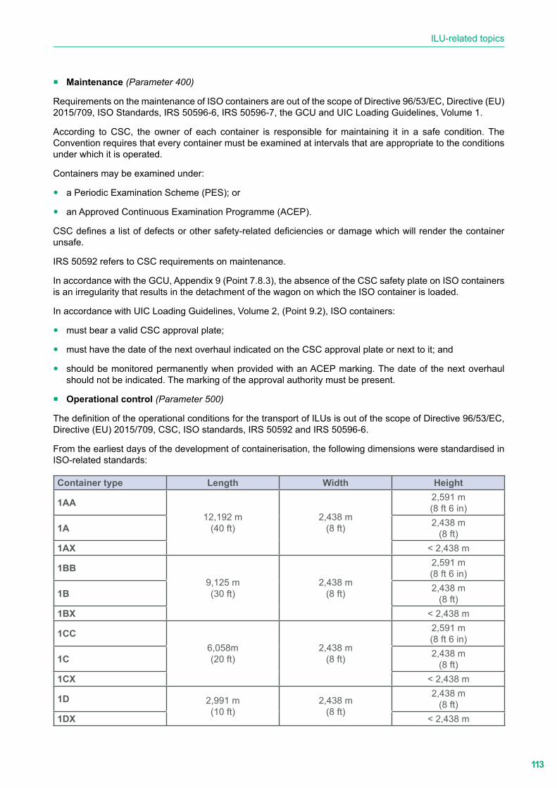
113
ILU-related topics
� Maintenance (Parameter 400)
Requirements on the maintenance of ISO containers are out of the scope of Directive 96/53/EC, Directive (EU) 2015/709, ISO Standards, IRS 50596-6, IRS 50596-7, the GCU and UIC Loading Guidelines, Volume 1.
According to CSC, the owner of each container is responsible for maintaining it in a safe condition. The Convention requires that every container must be examined at intervals that are appropriate to the conditions under which it is operated.
Containers may be examined under:
y a Periodic Examination Scheme (PES); or
y an Approved Continuous Examination Programme (ACEP).
CSC defines a list of defects or other safety-related deficiencies or damage which will render the container unsafe.
IRS 50592 refers to CSC requirements on maintenance.
In accordance with the GCU, Appendix 9 (Point 7.8.3), the absence of the CSC safety plate on ISO containers is an irregularity that results in the detachment of the wagon on which the ISO container is loaded.
In accordance with UIC Loading Guidelines, Volume 2, (Point 9.2), ISO containers:
y must bear a valid CSC approval plate;
y must have the date of the next overhaul indicated on the CSC approval plate or next to it; and
y should be monitored permanently when provided with an ACEP marking. The date of the next overhaul should not be indicated. The marking of the approval authority must be present.
� Operational control (Parameter 500)
The definition of the operational conditions for the transport of ILUs is out of the scope of Directive 96/53/EC, Directive (EU) 2015/709, CSC, ISO standards, IRS 50592 and IRS 50596-6.
From the earliest days of the development of containerisation, the following dimensions were standardised in ISO-related standards:
Container type Length Width Height
1AA12,192 m
(40 ft)2,438 m
(8 ft)
2,591 m(8 ft 6 in)
1A 2,438 m(8 ft)
1AX ˂ 2,438 m
1BB9,125 m(30 ft)
2,438 m(8 ft)
2,591 m(8 ft 6 in)
1B 2,438 m(8 ft)
1BX ˂ 2,438 m
1CC6,058m(20 ft)
2,438 m(8 ft)
2,591 m(8 ft 6 in)
1C 2,438 m(8 ft)
1CX ˂ 2,438 m
1D 2,991 m(10 ft)
2,438 m(8 ft)
2,438 m(8 ft)
1DX ˂ 2,438 m

114
Comparative analysis of the combined transport usages and standards (CACTUS) - Final Report
By the end of the 20th century, demand for the transport of 9 ft 6 in containers (high cube) became significant.
In 2013, ISO 668 was amended, introducing the following new types:
Container type Length Width Height1EEE 13,716 m
(45 ft)2,438 m
(8 ft)2,896 m(9 ft 6 in)1EE
1AAA 12,192 m(40 ft)
2,438 m(8 ft)
2,896 m(9 ft 6 in)
1BBB 9,125 m(30 ft)
2,438 m(8 ft)
2,896 m(9 ft 6 in)
1CCC 6,058m(20 ft)
2,438 m(8 ft)
2,896 m(9 ft 6 in)
The conveyance of these higher containers as a normal consignment was not always possible on all railway lines and the use of exceptional consignments was widespread in most countries.
As it is not feasible to extend the codification of ISO containers, the following solutions were found and introduced into the UIC code to reduce the number of exceptional consignments:
y Use of low floor flat wagons
y Transport on CT lines codified with a suitable code in accordance with IRS 50596-6 requirements and UIC Loading Guidelines, Volume 2
IRS 50596-6 requirements
IRS 50596-6 provides the operational conditions for the transport of ISO containers on CT lines as normal consignments.
To avoid extending the coding of ISO containers (considered impossible), IRS 50596-6, Point 2.2.2 defines the equivalence of the profiles of 8 ft, 8 ft 6 in, 9 ft 6 in high ISO containers and those of the swap bodies provided by Appendix C.1.
In particular:
1EEE, 1AAA, 1BBB and 1CCC (identified as ISO 45) → C44
1AA, 1BB and 1CC (identified as ISO 14) → C12
1A, 1B and 1C (identified as ISO 00) → C00
UIC Loading Guidelines operational conditions
If the conveyance of containers and swap bodies is performed using flat wagons other than those compliant with IRS 50571-4 and they are not provided with a WCC and correction number, IRS 50596-6 does not apply.
UIC Loading Guidelines, Volume 2, Point 9.0 provides the list of the equivalent values of the codes of ILUs that may be transported as a normal consignment on all lines (coded and non-coded) depending on the national networks and the following flat wagon characteristics.
Loading and securing guidelines
According to the GCU, Article 29, RUs shall ensure that shippers comply with the UIC Loading Guidelines in force.
In addition to the above-mentioned requirements, the UIC Loading Guidelines, Volume 2:
y provides all the necessary measures for the loading and securing of goods. They are designed to guarantee operating safety and ensure damage-free conveyance of goods (Loading method 9.2).

115
ILU-related topics
y provides guidelines and requirements for loading cargo on containers (stresses during transit acceleration in accordance with EN 12195-1, Table 3) and measures to ensure the stability of the cargo (Loading method 9.0.1).
Conditions for the technical transfer inspection of wagons
The GCU, including its appendices, sets out the conditions for the provision of wagons for use as a means of transport by RUs in national and international traffic within the scope of application of the COTIF in force.
Each RU shall carry out all the safety-related inspections referred to in Appendix 9 “Conditions for the technical transfer inspection of wagons”.
The GCU, Appendix 9, Annex 1 provides the catalogue of irregularities and the actions to be taken by qualified RU inspectors. The irregularities concerning ISO container bodies loaded on container carrier wagons are referenced in Points 7.5.1, 7.5.2, 7.5.4 to 7.5.7, 7.6, 7.7.1, 7.7.9 and 7.8.1 to 7.8.4.
� Certification (Parameter 600)
Certification of ISO containers is out of the scope of Directive 96/53/EC, Directive (EU) 2015/709, ISO 668, ISO 830, ISO 6346, the GCU and UIC Loading Guidelines, Volumes 1 & 2.
� Container safety approval (Parameter 600.2)
According to CSC, the approval of containers is made by governments (in the following Administrations) or by parties to which Administrations have delegated their responsibility for approving containers.
The International Maritime organisation (IMO) publishes the annual CSC Circulars that list the organisations entrusted to approve, test and inspect containers.
CSC, Annex I provides regulations for the approval of:
y New containers by design type (Chapter II);
y New containers by individual approval (Chapter III);
y Existing and new containers not approved at time of manufacture (Chapter IV); and
y Modified containers (Chapter V).
The approval is evidenced by the Safety Approval Plate. Once the Administration has notified the applicant that the container meets the CSC requirements, the manufacturer is entitled to affix the CSC Safety Approval Plate to the container.
The layout and content of the Safety Approval Plate are provided in the Appendix to CSC, Annex I. ISO 1496-1 to 5 and IRS 50592 refer to CSC.
5.1.2.3. Potential areas of improvement, cross-referencing and harmonisation needs
ISO standards define intermodal freight containers, related equipment and technology applicable to the intermodal, containerised movement of freight. They form a coherent body that helped harmonize national and regional standards and are cited as normative references in other international standards and in national, regional and international legislation.
ISO 668 and ISO 1496-1 to 5 provide requirements on the design and testing of:
� all types of general and specific (thermal, tank, bulk, platform and platform-based) containers;
� handling and securing equipment; and
� equipment to load, stow and secure freight containers on vessels and other conveyances.
ISO specific standards also provide requirements on:
116
Comparative analysis of the combined transport usages and standards (CACTUS) - Final Report
� equipment to load, stow and secure freight containers on vessels and other conveyances;
� identification of containers and their contents and electronic tagging;
� electronic and mechanical container seals;
� electronic data exchange and interchange message formats;
� container markings and container security, tracking and tracing from a design and application perspective; and
� terminology.
ISO 1496-1 to 5 have a common configuration that makes them easy to consult and understand. Cross-referencing to specific standards avoids overlaps and possible contradiction.
As is normal for ISO standards, they are reviewed by the relevant technical committee every five years to see if revision is required to keep them current and relevant.
The structure and process for reviewing ISO standards for freight containers can be considered best practice for the creation of a renewed set of EN standards on swap bodies, swap body components and securing equipment, and swap body identification and markings.
5.1.3. ILUs other than ISO containers and semi-trailers
Intermodal Loading Units other than ISO containers and semi-trailers designed for vertical transhipment, better known as swap bodies, may be divided into two categories:
� Swap bodies compliant with related EN standards.
� Non-EN standardised ILUs compliant with the requirements set out in IRS 50592 including:
y ILUs whose dimensions allow them to be coded according to IRS 50596-6;
y ILUs with a base width > 2,600 mm;
y ILUs which due to their dimensions or maximum gross mass may not be freely loaded onto CT wagons marked with wagon compatibility code C;
y hybrid ILUs (fitted with upper corner fittings but no grab handling grooves); and
y flat ILUs.
5.1.3.1. Overview of current regulations, standards and guidelines
The following regulations, standards and guidelines were considered by the project team when it performed the analysis on ILUs other than ISO containers and semi-trailers.
European legal framework
� 96/53/EC: Directive laying down for certain road vehicles circulating within the Community the maximum authorized dimensions in national and international traffic and the maximum authorized weights in international traffic
� EU/2015/719: Directive amending Council Directive 96/53/EC laying down for certain road vehicles circulating within the Community the maximum authorised dimensions in national and international traffic and the maximum authorised weights in international traffic
United Nations Economic Commission for Europe (UNECE)
� ADR: European agreement concerning the international carriage of dangerous goods by road, Ed. 2019

117
ILU-related topics
� ATP: Agreement for the international carriage of perishable foodstuff and on the special equipment to be used for this carriage, Ed. 2020
Intergovernmental Organisation for International Carriage by Rail (OTIF)
� RID: Regulation concerning the International Carriage of Dangerous Goods by Rail, Ed. 2019
European Committee for Standardization (CEN)
� EN 283: Swap bodies - Testing, Ed. 1991
� EN 284: Swap bodies - Non-stackable swap bodies of Class C - Dimensions and general requirements, Ed. 1992
� EN 452: Swap bodies - Swap bodies of Class A - Dimensions and general requirements, Ed. 1995
� EN 1432: Swap bodies - Swap tanks - Dimensions, requirements, test methods, operation condition, Ed. 1997
� EN 12406: Swap bodies - Thermal swap bodies of Class C - Dimensions and general requirements, Ed. 1999
� EN 12410: Swap bodies - Thermal swap bodies of Class A - Dimensions and general requirements, Ed. 1999
� CEN/TS 13853: Swap bodies for combined transport - Stackable swap bodies type C 745- S16 - Dimensions, design requirements and testing, Ed. 2003
� CEN/TS 14993: Swap bodies for combined transport - Stackable swap bodies type A 1371 - Dimensions, design requirements and testing, Ed. 2005
� EN 12640: Swap bodies - Thermal swap bodies of Class A - Dimensions and general requirements, Ed. 2019
� EN 12641-1: Intermodal loading units and commercial vehicles - Tarpaulins - Part 1: Minimum requirements, Ed. 2019
� EN 12641-2: Intermodal loading units and commercial vehicles - Tarpaulins - Part 2: Minimum requirements for curtainsiders, Ed. 2019
� EN 12642: Securing of cargo on road vehicles - Body structure of commercial vehicles - Minimum requirements, Ed. 2016
� EN 13044-1 + AC: Intermodal Loading Units - Marking - Part 1: Markings for identification, Ed. 2011/AC, 2014
� EN 13044-2: Intermodal Loading Units - Marking - Part 2: Markings of swap bodies related to rail operation, Ed. 2011
� pr EN 17321: Intermodal loading units and commercial vehicles - Transport stability of packages - Minimum requirements and tests (under approval)
� EN 12195-1 + AC: Load restraining on road vehicles - Safety - Part 1: Calculation of securing forces, Ed. 2014/1.AC, 2019
� EN 12195-2: Load restraint assemblies on road vehicles - Safety - Part 2: Web lashing made from man-made fibres, Ed. 2000
� EN 12195-3: Load restraint assemblies on road vehicles - Safety - Part 3: Lashing chains, Ed. 2001
� EN 12195-4: Load restraint assemblies on road vehicles - Safety - Part 4: Lashing steel wire ropes, Ed. 2003

118
Comparative analysis of the combined transport usages and standards (CACTUS) - Final Report
International Organization for Standardization (ISO)
� ISO 668: Series 1 freight containers - Classification, dimensions and ratings, Ed. 2000
� ISO 830: Freight containers - Vocabulary, Ed. 1999/Tech. Corr. 1, Ed. 2001
� ISO 1161: Series 1 freight containers - Corner and intermediate fittings - Specifications, Ed. 2016
International Union of Railways (UIC)
� IRS 50571-4: Wagons for combined transport - Vertical transhipment - Characteristics, Ed. 2020
� IRS 50592: Intermodal Loading Units (other than semi-trailers) for vertical transhipment and suitable for carriage on wagons - Minimum requirements, Ed. 2021
� IRS 50596-6: Conditions for coding intermodal loading units in combined transport, combined transport lines and wagons, Ed. 2018
� IRS 50596-7: Railway application - Rolling stock - Conformity assessment - Requirements for bodies performing the certification of coding in accordance with UIC Leaflet 596-6 (Competent Authorities), Ed. 2017
� Loading Guidelines, Volume 1: Code of practice for the loading and securing of goods on railway wagons - Principles, Ed. 2020
� Loading Guidelines, Volume 2: Code of practice for the loading and securing of goods on railway wagons - Goods, Ed. 2020
GCU Bureau
� GCU: General Contract of Use for wagons, Ed. 2020
5.1.3.2. Overlaps, duplications and contradictions
The goal of the comparative analysis of the documents listed in Point 5.1.3 is the identification of:
� the requirements provided by each document for the selected parameters (see Clause a of the current point);
� overlaps, duplications, contradictions and gaps (see Clause b of the current point); and
� potential cross-referencing, areas of improvement and harmonisation needs (see Point 5.1.1.3).
a. Parameters and items
The analysis is focused on the following parameters:
1 Definitions
2 Classification
3 Dimensions
3.1 External dimensions
3.2 Internal dimensions
4 Ratings
5 Load transfer areas
6 Intermediate support: dimensions and location
7 Gooseneck tunnel/steering tunnel: dimensions and location
8 Upper and bottom fittings
119
ILU-related topics
8.1 Upper (corner/intermediate) fittings: dimensions and location
8.2 Bottom (corner/intermediate) fittings: dimensions and location
8.3 Technical requirements
9 Grappler arm grooves: dimensions and location
10 Supporting legs: dimensions and location
11 Fork-lift pockets: dimensions and location
12 Slinging apertures: dimensions and location
13 Front stop (at the front-end wall)
14 Front fittings in the front face of the ILU
19 Body structure
20 Tarpaulins
21 Ladders
22 Walkways
24 Cargo securing
24.1 Anchor and lashing points
25 Load restraint and lashing devices for cargo securing
26 Interface between road chassis and ILU
27 Refrigeration and heating equipment
28 Thermal characteristics of the isothermal body
29 Devices for hanging cargo
30 Tank characteristics
100 Tests
101 General
102 Stacking
103 Lifting
103.1 Lifting from the grappler arm grooves
103.2 Lifting from the four upper fittings
103.3 Lifting from four bottom fittings
103.4 Lifting from the slinging apertures
103.5 Lifting from the fork-lift pockets
104 External restraint (longitudinal)
104.1 Static tests
104.2 Dynamic tests
106 Internal restraint (lateral)
107 Rigidity (longitudinal)
108 Rigidity (transverse)
109 Strength of end walls
109.1 Static tests

120
Comparative analysis of the combined transport usages and standards (CACTUS) - Final Report
109.2 Dynamic tests
110 Strength of side walls
111 Strength of the ILU body structure
112 Strength of the roof
113 Testing tarpaulins
114 Floor strength
115 Testing the stability of ILUs standing on support legs
116 Testing support legs
117 Testing ladders
118 Testing walkways
119 Pressure tests
120 Testing shoring slots
121 Testing load transfer areas
123 Weatherproofness
124 Testing lashing points for cargo security
125 Testing refrigeration/heating unit performance
126 Testing refrigeration/heating unit attachments
127 Testing the thermal characteristics of the isothermal body
128 Testing devices for hanging cargo
129 Concluding test
200 Design loadings
300 Identification and markings
300.1 Identification
300.2 Operational markings
400 Maintenance
500 Operational control
600 Certification
600.1 Codification
600.2 ILU approval
600.3 Coding plate delivery
b. Results of the dry and comparative analyses
The outputs of the dry analysis of the requirements on the relevant parameters (references to parameter numbers in brackets) provided by the selected documents are shown in Appendix B (SB_Dry analysis_sheet).
This point gives a summary of the outputs of the dry and comparative analyses and is focused on the requirements provided by the reference documents, highlighting, for each parameter:
� requirements provided by IRS 50592 and/or EN 284, EN 452, EN 1432, EN 12406, EN 12410, CEN/TS 13853, CEN/TS 14993 and ISO 668 and by other reference documents;
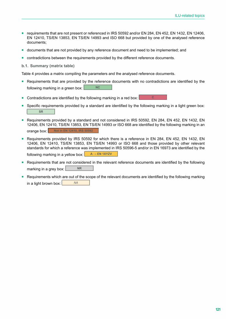
121
ILU-related topics
� requirements that are not present or referenced in IRS 50592 and/or EN 284, EN 452, EN 1432, EN 12406, EN 12410, TS/EN 13853, EN TS/EN 14993 and ISO 668 but provided by one of the analysed reference documents;
� documents that are not provided by any reference document and need to be implemented; and
� contradictions between the requirements provided by the different reference documents.
b.1. Summary (matrix table)
Table 4 provides a matrix compiling the parameters and the analysed reference documents.
� Requirements that are provided by the reference documents with no contradictions are identified by the
following marking in a green box: NC
� Contradictions are identified by the following marking in a red box: C
� Specific requirements provided by a standard are identified by the following marking in a light green box: SR
� Requirements provided by a standard and not considered in IRS 50592, EN 284, EN 452, EN 1432, EN 12406, EN 12410, TS/EN 13853, EN TS/EN 14993 or ISO 668 are identified by the following marking in an orange box: Not in EN 12410, IRS 50592
� Requirements provided by IRS 50592 for which there is a reference in EN 284, EN 452, EN 1432, EN 12406, EN 12410, TS/EN 13853, EN TS/EN 14993 or ISO 668 and those provided by other relevant standards for which a reference was implemented in IRS 50596-5 and/or in EN 16973 are identified by the
following marking in a yellow box: A → EN 1XYZV
� Requirements that are not considered in the relevant reference documents are identified by the following
marking in a grey box: NR
� Requirements which are out of the scope of the relevant documents are identified by the following marking
in a light brown box: NA
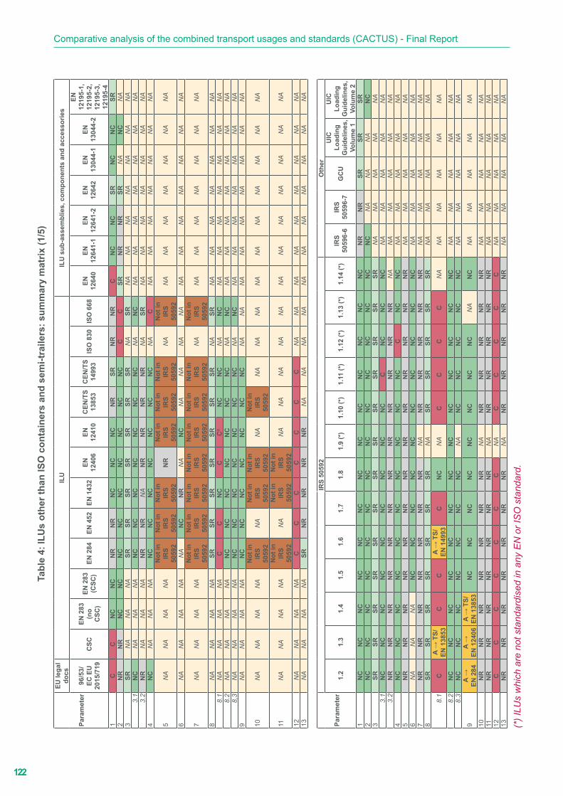
122
Comparative analysis of the combined transport usages and standards (CACTUS) - Final ReportTa
ble
4: IL
Us
othe
r tha
n IS
O c
onta
iner
s an
d se
mi-t
raile
rs: s
umm
ary
mat
rix (1
/5)
Para
met
er
EU le
gal
docs
ILU
ILU
sub
-ass
embl
ies,
com
pone
nts
and
acce
ssor
ies
96/5
3/EC
EU
20
15/7
19C
SCEN
283
(n
o C
SC)
EN 2
83
(CSC
)EN
284
EN 4
52EN
143
2EN
12
406
EN
1241
0C
EN/T
S 13
853
CEN
/TS
1499
3IS
O 8
30IS
O 6
68EN
12
640
EN
1264
1-1
EN
1264
1-2
EN
1264
2EN
13
044-
1EN
13
044-
2
EN
1219
5-1,
12
195-
2,
1219
5-3,
12
195-
41
CC
NC
NC
NR
NR
NC
NC
NC
NR
SRN
RN
RC
NC
NC
SRN
CN
CSR
2N
RN
RN
CN
CN
CN
CN
CN
CN
CN
CN
CC
CSR
NR
NR
SRN
AN
CN
A3
SRN
AN
AN
ASR
SRSR
SRSR
SRSR
NA
SRN
AN
AN
AN
AN
AN
AN
A3.
1N
CN
AN
AN
AN
CN
CN
CN
CN
CN
CN
CN
AN
CN
AN
AN
AN
AN
AN
AN
A3.
2N
RN
AN
AN
AN
RN
RN
AN
RN
RN
RN
RN
ASR
NA
NA
NA
NA
NA
NA
NA
4N
CN
AN
AN
AN
CN
CN
CN
CN
CN
CN
CN
AC
NA
NA
NA
NA
NA
NA
NA
5N
AN
AN
AN
AN
ot in
IR
S50
592
Not
in
IRS
5059
2
Not
in
IRS
5059
2N
RN
ot in
IR
S50
592
Not
in
IRS
5059
2
Not
in
IRS
5059
2N
AN
ot in
IR
S50
592
NA
NA
NA
NA
NA
NA
NA
6N
AN
AN
AN
AN
AN
CN
RN
AN
CN
AN
AN
AN
AN
AN
AN
AN
AN
AN
AN
A
7N
AN
AN
AN
AN
ot in
IR
S50
592
Not
in
IRS
5059
2
Not
in
IRS
5059
2
Not
in
IRS
5059
2
Not
in
IRS
5059
2
Not
in
IRS
5059
2
Not
in
IRS
5059
2N
AN
ot in
IR
S50
592
NA
NA
NA
NA
NA
NA
NA
8N
AN
AN
AN
ASR
SRSR
SRSR
SRSR
NA
SRN
AN
AN
AN
AN
AN
AN
A8.
1N
AN
AN
AN
AC
CN
CC
C²
NC
NC
NA
NC
NA
NA
NA
NA
NA
NA
NA
8.2
NA
NA
NA
NA
NC
NC
NC
NC
NC
NC
NC
NA
NC
NA
NA
NA
NA
NA
NA
NA
8,3
NA
NA
NA
NA
NC
NC
NC
NC
NC
NC
NC
NA
NC
NA
NA
NA
NA
NA
NA
NA
9N
AN
AN
AN
AN
CN
CN
CN
CN
CN
CN
CN
AN
AN
AN
AN
AN
AN
AN
AN
A
10N
AN
AN
AN
AN
ot in
IR
S50
592
NA
Not
in
IRS
5059
2
Not
in
IRS
5059
2N
AN
ot in
IR
S50
592
NA
NA
NA
NA
NA
NA
NA
NA
NA
NA
11N
AN
AN
AN
AN
ot in
IR
S50
592
NA
Not
in
IRS
5059
2
Not
in
IRS
5059
2N
AN
AN
AN
AN
AN
AN
AN
AN
AN
AN
AN
A
12N
AN
AN
AN
AC
CC
CC
CC
NA
NA
NA
NA
NA
NA
NA
NA
NA
13N
AN
AN
AN
ASR
NR
NR
NR
NR
NA
NA
NA
NA
NA
NA
NA
NA
NA
NA
NA
Para
met
er
IRS
5059
2O
ther
1.2
1.3
1.4
1.5
1.6
1.7
1.8
1.9
(*)
1.10
(*)
1.11
(*)
1.12
(*)
1.13
(*)
1.14
(*)
IRS
5059
6-6
IRS
5059
6-7
GC
U
UIC
Lo
adin
g G
uide
lines
, Vo
lum
e 1
UIC
Lo
adin
g G
uide
lines
, Vo
lum
e 2
1N
CN
CN
CN
CN
CN
CN
CN
CN
CN
CN
CN
CN
CN
RN
RSR
SRSR
2N
CN
CN
CN
CN
CN
CN
CN
CN
CN
CN
CN
CN
CN
CN
AN
AN
AN
C3
SRSR
SRSR
SRSR
SRSR
SRSR
SRSR
SRN
AN
AN
AN
AN
A3.
1N
CN
CN
CN
CN
CN
CN
CN
CN
CC
NC
NC
NC
NA
NA
NA
NA
NA
3.2
NR
NR
NR
NR
NR
NR
NR
NR
NR
NR
NR
NR
NA
NA
NA
NA
NA
NA
4N
CN
CN
CN
CN
CN
CN
CN
CN
CN
CC
NC
NC
NA
NA
NA
NA
NA
5N
RN
RN
RN
RN
RN
RN
RN
RN
RN
RN
RN
RN
RN
AN
AN
AN
AN
A6
NA
NA
NA
NC
NC
NC
NC
NC
NC
NC
NC
NC
NC
NA
NA
NA
NA
NA
7N
RN
RN
RN
RN
RN
RN
RN
AN
RN
RN
RN
RN
RN
AN
AN
AN
AN
A8
SRSR
SRSR
SRSR
SRN
ASR
SRSR
SRSR
NA
NA
NA
NA
NA
8.1
CA
→ T
S/EN
138
53C
CA
→ T
S/EN
149
93C
NC
NA
CC
CC
NA
NA
NA
NA
NA
NA
8.2
NC
NC
NC
NC
NC
NC
NC
NC
NC
NC
NC
NC
NC
NA
NA
NA
NA
NA
8.3
NC
NC
NC
NC
NC
NC
NC
NA
NC
NC
NC
NC
NC
NA
NA
NA
NA
NA
9A
→EN
284
A →
EN 1
2406
A →
TS/
EN 1
3853
NC
NC
NC
NC
NC
NC
NC
NC
NA
NC
NA
NA
NA
NA
NA
10N
RN
RN
RN
RN
RN
RN
RN
AN
RN
RN
RN
RN
RN
AN
AN
AN
AN
A11
NR
NR
NR
NR
NR
NR
NR
NA
NR
NR
NR
NR
NR
NA
NA
NA
NA
NA
12C
CC
CC
CC
NA
CC
CC
CN
AN
AN
AN
AN
A13
NR
NR
NR
NR
NR
NR
NR
NA
NR
NR
NR
NR
NR
NA
NA
NA
NA
NA
(*) I
LUs
whi
ch a
re n
ot s
tand
ardi
sed
in a
ny E
N o
r IS
O s
tand
ard.

123
ILU-related topicsTa
ble
4: IL
Us
othe
r tha
n IS
O c
onta
iner
s an
d se
mi-t
raile
rs: s
umm
ary
mat
rix (2
/5)
Para
met
er
EU le
gal
docs
ILU
ILU
sub
-ass
embl
ies,
com
pone
nts
and
acce
ssor
ies
96/5
3/EC
EU
20
15/7
19C
SCEN
283
(n
o C
SC)
EN 2
83
(CSC
)EN
284
EN 4
52EN
143
2EN
12
406
EN
1241
0C
EN/T
S 13
853
CEN
/TS
1499
3IS
O 8
30IS
O 6
68EN
12
640
EN
1264
1-1
EN
1264
1-2
EN
1264
2EN
13
044-
1EN
13
044-
2
EN
1219
5-1,
12
195-
2,
1219
5-3,
12
195-
414
NA
NA
NA
NA
NR
SRN
RN
RSR
NR
SRN
AN
AN
AN
AN
AN
AN
AN
AN
A
19N
AN
AN
AN
AN
CN
CC
NC
NC
NC
NC
NA
NA
NA
NA
NA
A →
EN
s (1
)N
AN
AN
A
20N
AN
AN
AN
AN
CN
RN
AN
AN
AN
AN
AN
AN
AN
AN
CN
CN
AN
AN
AN
A21
NA
NA
NA
NA
NR
NR
SRSR
NR
NR
NR
NA
NA
NA
NA
NA
NA
NA
NA
NA
22N
AN
AN
AN
AN
RN
RSR
NR
NR
NR
NR
NA
NA
NA
NA
NA
NA
NA
NA
NA
24N
AN
AN
AN
ASR
NR
NA
NR
NR
SRSR
NA
NA
SRN
AN
AN
AN
AN
AN
A24
.1N
AN
AN
AN
AN
CN
RN
AN
RN
RN
CN
CN
AN
AN
CN
AN
AN
AN
AN
AN
A25
NA
NA
NA
NA
NA
NA
NA
NA
NA
NA
NA
NA
NA
NC
NA
NA
NA
NA
NA
NC
26N
AN
AN
AN
AN
RSR
NR
NR
NC
NR
NR
NA
NA
NA
NA
NA
NA
NA
NA
NA
27N
AN
AN
AN
AN
AN
AN
AN
CN
CN
AN
AN
AN
AN
AN
AN
AN
AN
AN
AN
A28
NA
NA
NA
NA
NA
NA
NA
NC
NC
NA
NA
NA
NA
NA
NA
NA
NA
NA
NA
NA
29N
AN
AN
AN
AN
AN
AN
ASR
SRN
AN
AN
AN
AN
AN
AN
AN
AN
AN
AN
A30
NA
NA
NA
NA
NA
NA
SRN
AN
AN
AN
AN
AN
AN
AN
AN
AN
AN
AN
AN
A10
0N
AN
CN
CN
CN
CN
CN
CN
CN
CN
CN
CN
CN
CN
CN
CN
CN
CN
CN
CN
C10
1N
AN
CN
CN
CN
CN
CN
CN
CN
CN
CN
CN
CN
CN
CN
CN
CN
CN
CN
CN
C10
2N
AN
CN
RN
RN
AN
AN
CN
AN
AN
CN
CN
AN
AN
AN
AN
AN
AN
AN
AN
A10
3N
AN
CN
CN
CN
CN
CN
CN
CN
CN
CN
CN
AN
AN
AN
AN
AN
AN
AN
AN
A10
3.1
NA
NC
NC
NC
NC
NC
CN
CN
CN
CN
CN
AN
AN
AN
AN
AN
AN
AN
AN
A10
3.2
NA
NC
NR
NR
NA
NA
NC
NA
NA
NC
NC
NA
NA
NA
NA
NA
NA
NA
NA
NA
103.
3N
AN
CN
CN
CN
CN
CN
CN
CN
CN
CN
CN
AN
AN
AN
AN
AN
AN
AN
AN
A10
3.4
NA
NC
NC
NC
NC
NC
NC
NC
NC
NC
NC
NA
NA
NA
NA
NA
NA
NA
NA
NA
Para
met
er
IRS
5059
2O
ther
1.2
1.3
1.4
1.5
1.6
1.7
1.8
1.9
(*)
1.10
(*)
1.11
(*)
1.12
(*)
1.13
(*)
1.14
(*)
IRS
5059
6-6
IRS
5059
6-7
GC
U
UIC
Lo
adin
g G
uide
lines
, Vo
lum
e 1
UIC
Lo
adin
g G
uide
lines
, Vo
lum
e 2
14N
RN
RN
RN
RN
RN
RN
RN
AN
RN
RN
RN
RN
RN
AN
AN
AN
AN
A
19A
→EN
284
A →
TS/
EN 1
3853
A →
EN 1
2406
A →
EN 4
52A
→ T
S/EN
149
93A
→EN
124
10C
SRSR
SRSR
SRSR
NA
NA
NA
NA
NA
20A
→EN
284
NA
NA
A →
EN 4
52N
AN
AN
AN
AN
CN
CN
CN
CN
AN
AN
AN
AN
AN
A
21N
RN
RN
RN
RN
RN
RN
RN
AN
RN
RN
RN
RN
AN
AN
AN
AN
AN
A22
NR
NR
NR
NR
NR
NR
NR
NA
NR
NR
NR
NR
NA
NA
NA
NA
NA
NA
24N
RN
RN
AN
RN
RN
AN
AN
AN
RN
RN
RN
RN
CN
AN
AN
AN
AN
A24
.1N
RN
RN
AN
RN
RN
AN
AN
AN
RN
RN
RN
RN
CN
AN
AN
AN
AN
A25
NA
NA
NA
NA
NA
NA
NA
NA
NA
NA
NA
NA
NA
NA
NA
NA
NC
NC
26N
RN
RN
RN
RN
RN
RN
RN
AN
RN
RN
RN
RN
RN
AN
AN
AN
AN
A27
NA
NA
NC
NA
NA
NC
NA
NA
NA
NA
NA
NA
NA
NA
NA
NA
NA
NA
28N
AN
AN
CN
AN
AN
CN
AN
AN
AN
AN
AN
AN
AN
AN
AN
AN
AN
A29
NA
NA
NR
NA
NA
NR
NA
NA
NA
NA
NA
NA
NA
NA
NA
NA
NA
NA
30N
AN
AN
AN
AN
AN
CN
AN
AN
AN
AN
AN
AN
AN
AN
AN
AN
AN
A10
0N
CN
CN
CN
CN
CN
CN
CN
CN
CN
CN
CN
CN
CN
CN
CN
CN
CN
C10
1N
CN
CN
CN
CN
CN
CN
CN
CN
CN
CN
CN
CN
CN
CN
CN
CN
CN
C10
2N
AN
CN
AN
AN
CN
AN
AN
AN
AN
AN
AN
RN
AN
AN
AN
AN
AN
A10
3N
CN
CN
CN
CN
CN
CN
CN
CN
CN
CN
CN
CN
CN
AN
AN
AN
AN
A
103.
1A
→EN
283
A →
TS/
EN 1
3853
NC
A →
EN 2
83A
→ T
S/EN
149
93N
CN
CC
A →
EN 2
83A
→EN
283
A →
EN 2
83N
AA
→EN
283
NA
NA
NA
NA
NA
103.
2N
AA
→ C
SCN
AN
AA
→ C
SCN
AN
CN
AA
→ C
SCA
→ C
SCA
→ C
SCA
→ C
SCN
AN
AN
AN
AN
AN
A10
3.3
NC
NC
NC
NC
NC
NC
NC
NC
NC
NC
NC
NC
NC
NA
NA
NA
NA
NA
103.
4N
CN
CN
CN
CN
CN
CN
CN
CN
CN
CN
CN
CN
CN
AN
AN
AN
AN
A
(*) I
LUs
whi
ch a
re n
ot s
tand
ardi
sed
in a
ny E
N o
r IS
O s
tand
ard
(1) E
N 2
84, E
N 4
52, E
N 1
2406
, EN
124
10, C
EN
/TS
138
53 a
nd C
EN
/TS
149
93

124
Comparative analysis of the combined transport usages and standards (CACTUS) - Final Report
Tabl
e 4:
ILU
s ot
her t
han
ISO
con
tain
ers
and
sem
i-tra
ilers
: sum
mar
y m
atrix
(3/5
)
Para
met
er
EU le
gal
docs
ILU
ILU
sub
-ass
embl
ies,
com
pone
nts
and
acce
ssor
ies
96/5
3/EC
EU
20
15/7
19C
SCEN
283
(n
o C
SC)
EN 2
83
(CSC
)EN
284
EN 4
52EN
143
2EN
12
406
EN
1241
0C
EN/T
S 13
853
CEN
/TS
1499
3IS
O 8
30IS
O 6
68EN
12
640
EN
1264
1-1
EN
1264
1-2
EN
1264
2EN
13
044-
1EN
13
044-
2
EN
1219
5-1,
12
195-
2,
1219
5-3,
12
195-
410
3.5
NA
CN
CC
NC
NA
NA
NC
NA
NC
NA
NA
NA
NA
NA
NA
NA
NA
NA
NA
104
NA
NC
(**)
NC
NC
NC
NC
NC
NC
NC
NC
(**)
NC
(**)
NA
NA
NA
NA
NA
NA
NA
NA
NA
104.
1N
AN
CN
CN
CN
CN
CN
CN
CN
CN
CN
CN
AN
AN
AN
AN
AN
AN
AN
AN
A10
4.2
NA
NR
NC
NC
NC
NC
NC
NC
NC
NR
NR
NA
NA
NA
NA
NA
NA
NA
NA
NA
106
NA
NR
NR
NR
NR
NR
NC
NR
NR
NA
NA
NA
NA
NA
NA
NA
NA
NA
NA
NA
107
NA
NR
NR
NR
NR
NR
NR
SRSR
NR
NR
NA
NA
NA
NA
NA
NA
NA
NA
NA
108
NA
NC
NA
NC
NR
NR
NR
NR
NR
NC
NC
NA
NA
NA
NA
NA
NA
NA
NA
NA
109
NA
NC
NC
NC
NC
NC
NA
NC
NC
NC
NC
NA
NA
NA
NA
NA
NA
NA
NA
NA
109.
1N
AN
CN
CN
CN
CN
CN
AN
CN
CN
CN
CN
AN
AN
AN
AN
AC
NA
NA
NA
109.
2N
AN
CN
CN
CN
CN
CN
AN
CN
CN
CN
CN
AN
AN
AN
AN
AC
NA
NA
NA
110
NA
SR (2
)N
CN
CN
CN
CN
AN
CN
CN
C (2
)N
C (2
)N
AN
AN
AN
AN
AC
NA
NA
NA
111
NA
SR (3
)N
CN
C (3
)N
CN
CSR
(4)
SRSR
NC
(3)
NC
(3)
NA
NA
NA
NA
NA
NC
NA
NA
NA
112
NA
NC
NC
NR
NR
NR
NA
NC
NC
NC
NC
NA
NA
NA
NA
NA
NA
NA
NA
NA
113
NA
NA
NR
NR
NR
NR
NA
NA
NA
NA
NA
NA
NA
NA
SRSR
NA
NA
NA
NA
114
NA
CC
CC
CN
AC
CC
CN
AN
AN
AN
AN
AN
AN
AN
AN
A11
5N
AN
AN
CN
CN
CN
AN
CN
CN
AN
CN
AN
AN
AN
AN
AN
AN
AN
AN
AN
A11
6N
AN
AN
CN
CN
CN
AN
CN
CN
AN
CN
AN
AN
AN
AN
AN
AN
AN
AN
AN
A11
7N
AN
AN
RN
RN
RN
RN
CN
RN
RN
AN
AN
AN
AN
AN
AN
AN
AN
AN
AN
A
Para
met
er
IRS
5059
2O
ther
1.2
1.3
1.4
1.5
1.6
1.7
1.8
1.9
(*)
1.10
(*)
1.11
(*)
1.12
(*)
1.13
(*)
1.14
(*)
IRS
5059
6-6
IRS
5059
6-7
GC
U
UIC
Lo
adin
g G
uide
lines
, Vo
lum
e 1
UIC
Lo
adin
g G
uide
lines
, Vo
lum
e 2
103.
5N
CN
CN
AN
AN
AN
AN
AN
AN
CN
CN
CN
CN
CN
AN
AN
AN
AN
A10
4N
CN
CN
CN
CN
CN
CN
CN
CN
CN
CN
CN
CN
CN
AN
AN
AN
AN
A10
4.1
NC
NC
NC
NC
NC
NC
NC
NC
NC
NC
NC
NC
NC
NA
NA
NA
NA
NA
104.
2N
CN
CN
CN
CN
CN
CN
CN
CN
CN
CN
CN
CN
CN
AN
AN
AN
AN
A10
6N
RN
RN
RN
RN
RN
RN
CN
RN
RN
CN
CN
CN
RN
AN
AN
AN
AN
A10
7N
RN
RN
RN
RN
RN
RN
RN
RN
RN
RN
RN
RN
RN
AN
AN
AN
AN
A10
8N
RN
RN
RN
RN
RN
RN
RN
RN
RN
RN
RN
RN
RN
AN
AN
AN
AN
A10
9N
CN
CN
CN
CN
CN
CN
AN
AN
CN
CN
CN
CN
AN
AN
AN
AN
AN
A10
9.1
NC
NC
NC
NC
NC
NC
NA
NA
NC
NC
NC
NC
NA
NA
NA
NA
NA
NA
109.
2N
CN
CN
CN
CN
CN
CN
AN
AN
CN
CN
CN
CN
AN
AN
AN
AN
AN
A11
0N
CN
C (2
)N
CN
CN
C (2
)N
CN
AN
AN
CN
CN
CN
CN
AN
AN
AN
AN
AN
A
111
A →
EN
283
, EN
284
, EN
452
, EN
124
06, E
N 1
2410
, CEN
/TS
1385
3an
d C
EN/T
S 14
993
SRN
AN
CN
CN
CN
AN
AN
AN
AN
AN
A
112
CC
CC
CC
CN
AN
AC
CC
NA
NA
NA
NA
NA
NA
113
NC
NA
NA
NC
NA
NA
NA
NA
NC
NC
NC
NC
NA
NA
NA
NA
NA
NA
114
CN
AN
AC
NA
NA
NA
NA
CC
CC
NA
NA
NA
NA
NA
NA
115
NR
NR
NR
NA
NA
NA
NC
NA
NR
NR
NA
NA
NA
NA
NA
NA
NA
NA
116
NR
NR
NR
NA
NA
NA
NC
NR
NR
NR
NA
NA
NA
NA
NA
NA
NA
NA
117
NR
NR
NR
NR
NR
NR
NC
NA
NR
NR
NR
NR
NA
NA
NA
NA
NA
NA
(*) I
LUs
whi
ch a
re n
ot s
tand
ardi
sed
in a
ny E
N o
r IS
O s
tand
ard
(**)
CS
C, C
EN
/TS
138
53 a
nd C
EN
/TS
149
93 p
rovi
de re
quire
men
ts o
nly
for s
tatic
test
s(2
) The
val
ue o
f the
test
forc
e ap
plie
d to
sta
ckab
le IL
Us
(0.6
0 P
xg) i
s hi
gher
than
that
app
lied
to n
on-s
tack
able
ILU
s (0
.30
Pxg
)(3
) Spe
cific
requ
irem
ent f
or s
tack
able
ILU
s(4
) Spe
cific
requ
irem
ent f
or re
frige
rate
d IL
Us
equi
pped
with
refri
gera
ting/
heat
ing
equi
pmen
t

125
ILU-related topics
Tabl
e 4:
ILU
s ot
her t
han
ISO
con
tain
ers
and
sem
i-tra
ilers
: sum
mar
y m
atrix
(4/5
)
Para
met
er
EU le
gal
docs
ILU
ILU
sub
-ass
embl
ies,
com
pone
nts
and
acce
ssor
ies
96/5
3/EC
EU
20
15/7
19C
SCEN
283
(n
o C
SC)
EN 2
83
(CSC
)EN
284
EN 4
52EN
143
2EN
12
406
EN
1241
0C
EN/T
S 13
853
CEN
/TS
1499
3IS
O 8
30IS
O 6
68EN
12
640
EN
1264
1-1
EN
1264
1-2
EN
1264
2EN
13
044-
1EN
13
044-
2
EN
1219
5-1,
12
195-
2,
1219
5-3,
12
195-
411
8N
AN
AN
RN
RN
RN
RN
CN
RN
RN
AN
AN
AN
AN
AN
AN
AN
AN
AN
AN
A11
9N
AN
AN
AN
AN
AN
AN
CN
AN
AN
AN
AN
AN
AN
AN
AN
AN
AN
AN
AN
A12
0N
AN
AN
R (5
)N
R (5
)N
R (5
)N
R (5
)N
AN
AN
AN
R (5
)N
R (5
)N
AN
AN
AN
AN
AN
AN
AN
AN
A12
1N
AN
AN
AN
AN
AN
AN
CN
AN
AN
AN
AN
AN
AN
AN
AN
AN
AN
AN
AN
A12
3N
AN
AN
CN
CN
CN
CN
RN
RN
RN
CN
CN
AN
AN
AN
AN
AN
AN
AN
AN
A12
4N
AN
AN
RN
RN
CN
RN
AN
AN
AN
CN
CN
AN
AN
CN
AN
AN
AN
AN
AN
A12
5N
AN
AN
AN
AN
AN
AN
AN
CN
CN
AN
AN
AN
AN
AN
AN
AN
AN
AN
AN
A12
6N
AN
AN
AN
AN
AN
AN
AN
CN
CN
AN
AN
AN
AN
AN
AN
AN
AN
AN
AN
A12
7N
AN
AN
AN
AN
AN
AN
AN
CN
CN
AN
AN
AN
AN
AN
AN
AN
AN
AN
AN
A12
8N
AN
AN
AN
AN
AN
AN
ASR
SRN
AN
AN
AN
AN
AN
AN
AN
AN
AN
AN
A12
9N
AN
AN
RN
RN
RN
RN
RN
RN
RN
RN
RN
AN
AN
AN
AN
AN
AN
AN
AN
A20
0N
AN
CN
CN
CN
CN
CN
CN
CN
CN
CN
CN
CN
CSR
NC
NC
NC
NA
NA
SR30
0N
ASR
NA
NA
SRSR
SRSR
SRSR
SRN
AN
ASR
SRSR
SRSR
SRN
A30
0.1
NA
NA
NA
NA
CC
CC
CC
CN
AN
ASR
SRSR
SRN
CN
CN
A30
0.2
NA
NA
NA
NA
NC
NC
NC
NC
NC
NC
NC
NA
NA
SRSR
SRSR
NC
NC
NA
400
NA
CN
AN
AN
RN
RN
RN
RN
RN
RN
RN
AN
ASR
NR
NR
SRN
AN
AN
A
Para
met
er
IRS
5059
2O
ther
1.2
1.3
1.4
1.5
1.6
1.7
1.8
1.9
(*)
1.10
(*)
1.11
(*)
1.12
(*)
1.13
(*)
1.14
(*)
IRS
5059
6-6
IRS
5059
6-7
GC
U
UIC
Lo
adin
g G
uide
lines
, Vo
lum
e 1
UIC
Lo
adin
g G
uide
lines
, Vo
lum
e 2
118
NA
NA
NR
NR
NR
NR
NC
NR
NR
NA
NA
NA
NA
NA
NA
NA
NA
NA
119
NA
NA
NA
NA
NA
NA
A →
EN
14
32N
AN
AN
AN
AN
AN
AN
AN
AN
AN
AN
A
120
NR
(5)
NR
(5)
NA
NR
(5)
NR
(5)
NA
NA
NA
NR
(5)
NR
(5)
NR
(5)
NR
(5)
NA
NA
NA
NA
NA
NA
121
NA
NA
NA
NA
NA
NA
NC
NA
NA
NA
NA
NA
NA
NA
NA
NA
NA
NA
123
NR
NR
NR
NR
NR
NR
NR
NA
NR
NR
NR
NR
NA
NA
NA
NA
NA
NA
124
NR
NR
NR
NR
NR
NR
NA
NA
NR
NR
NR
NR
NA
NA
NA
NA
NA
NA
125
NA
NA
NC
NA
NA
NC
NA
NA
NA
NA
NA
NA
NA
NA
NA
NA
NA
NA
126
NA
NA
NC
NA
NA
NC
NA
NA
NA
NA
NA
NA
NA
NA
NA
NA
NA
NA
127
NA
NA
NC
NA
NA
NC
NA
NA
NA
NA
NA
NA
NA
NA
NA
NA
NA
NA
128
NA
NA
NR
NA
NA
NR
NA
NA
NA
NA
NA
NA
NA
NA
NA
NA
NA
NA
129
A →
EN
283
, EN
284
, EN
452
, EN
124
06, E
N 1
2410
, CEN
/TS
1385
3 an
d C
EN/T
S 14
993
NA
NA
NA
NA
NA
200
NC
NC
NC
NC
NC
NC
NC
NC
NC
NC
NC
NC
NC
NA
NA
NA
NA
NA
300
SRSR
SRSR
SRSR
SRSR
SRSR
SRSR
SRSR
NA
NA
NA
SR30
0.1
NC
NC
NC
NC
NC
NC
NC
NC
NC
NC
NC
NC
NC
NC
NA
NA
NA
NC
300.
2A
→ E
N 2
83, E
N 2
84, E
N 4
52, E
N 1
2406
, EN
124
10, C
EN/T
S 13
853
and
CEN
/TS
1499
3N
AN
AN
AN
AN
C40
0C
CC
CC
CC
CC
CC
CC
NA
NA
NA
NA
NA

126
Comparative analysis of the combined transport usages and standards (CACTUS) - Final Report
Tabl
e 4:
ILU
s ot
her t
han
ISO
con
tain
ers
and
sem
i-tra
ilers
: sum
mar
y m
atrix
(5/5
)
Para
met
er
EU le
gal
docs
ILU
ILU
sub
-ass
embl
ies,
com
pone
nts
and
acce
ssor
ies
96/5
3/EC
EU
20
15/7
19C
SCEN
283
(n
o C
SC)
EN 2
83
(CSC
)EN
284
EN 4
52EN
143
2EN
12
406
EN
1241
0C
EN/T
S 13
853
CEN
/TS
1499
3IS
O 8
30IS
O 6
68EN
12
640
EN
1264
1-1
EN
1264
1-2
EN
1264
2EN
13
044-
1EN
13
044-
2
EN
1219
5-1,
12
195-
2,
1219
5-3,
12
195-
450
0N
AN
AN
AN
AN
RN
RN
RN
RN
RN
RN
RN
AN
AN
AN
AN
AN
AN
AN
ASR
600
NA
NA
NA
NA
NR
NR
NR
NR
NR
NR
NR
NA
NA
NA
NA
NA
NA
NA
CN
A60
0.1
NA
NA
NA
NA
NR
NR
NR
NR
NR
NR
NR
NA
NA
NA
NA
NA
NA
NA
CN
A60
0.2
NA
NA
NA
NA
NR
NR
NR
NR
NR
NR
NR
NA
NA
NA
NA
NA
NA
NA
CN
A60
0.3
NA
NA
NA
NA
NR
NR
NR
NR
NR
NR
NR
NA
NA
NA
NA
NA
NA
NA
CN
A
Para
met
er
IRS
5059
2O
ther
1.2
1.3
1.4
1.5
1.6
1.7
1.8
1.9
(*)
1.10
(*)
1.11
(*)
1.12
(*)
1.13
(*)
1.14
(*)
IRS
5059
6-6
IRS
5059
6-7
GC
U
UIC
Lo
adin
g G
uide
lines
, Vo
lum
e 1
UIC
Lo
adin
g G
uide
lines
, Vo
lum
e 2
500
NR
NR
NR
NR
NR
NR
NR
NR
NR
NR
NR
NR
NR
NA
NA
NC
NA
NC
600
NC
NC
NC
NC
NC
NC
NC
NC
NC
NC
NC
NC
NC
NC
NC
NA
NA
NA
600.
1N
CN
CN
CN
CN
CN
CN
CN
CN
CN
CN
CN
CN
CN
CN
CN
AN
AN
A60
0.2
NC
NC
NC
NC
NC
NC
NC
NC
NC
NC
NC
NC
NC
NC
NC
NA
NA
NA
600.
3N
CN
CN
CN
CN
CN
CN
CN
CN
CN
CN
CN
CN
CN
CN
CN
AN
AN
A

127
ILU-related topics
b.2. Summary of the outputs of the performed analysis
A preliminary consideration concerns the applicability of the International Convention for Safe Containers (CSC) to swap bodies.
The International Convention for Safe Containers (CSC 1972) has two goals:
� To maintain a high level of safety of human life in the transport and handling of containers by providing tests, procedures and strength requirements.
� To facilitate the international transport of containers by providing uniform international safety regulations, equally applicable to all modes of transport.
CSC 1972 sets out procedures whereby containers used in international transport must be approved for safety by the Administration of a Contracting Party or by an organisation acting on their behalf. This approval is evidenced by the Safety Approval Plate and should be recognised by other Contracting Parties.
CSC 1972 has been amended several times and the current edition is CSC 2014 which contains three annexes:
� Annex I provides regulations for the testing, inspection, approval and maintenance of containers.
� Annex II provides requirements on structural safety and tests.
� Annex III provides specific control measures for authorised officers to assess the integrity of structurally sensitive components of containers and to decide whether they should be stopped until remedial action has been taken.
The Convention also has a supplement on recommendations for harmonised interpretation and implementation of the International Convention for Safe Containers, edition 1972, as amended. This supplement does not constitute any part of the convention.
According to the above-mentioned supplement, ‘swap body’ is a term that can be used for describing containers that generally operate solely within the wider continent of Europe.
CSC does not apply to:
� swap bodies designed and used for carriage by road only or by rail and road only and which are without stacking capability and top lift facilities; and
� swap bodies transported by sea on condition that they are mounted on a road vehicle or rail wagon.
However, CSC applies to swap bodies used in transoceanic services.
� Definitions (Parameter 1)
Directive (EU) 2015/719 amending Directive 96/53/EC considers intermodal transport and sets out requirements for freight road vehicles linked to the conveyance of swap bodies, but there is no definition of ‘swap body’ in the two directives.
There is no definition in EN 284, EN 452 and CEN/TS 13853.
ISO 830 and ISO 668 do not provide definitions for ‘swap body’ and ‘Intermodal Loading Unit’. They are considered to be ‘freight containers’ (see definition below):
Point 3.1: Freight container article of transport equipment:
a. of a permanent character and accordingly strong enough to be suitable for repeated use,
b. specially designed to facilitate the carriage of goods by one or more modes of transport, without intermediate reloading,
c. fitted with devices permitting its ready handling, particularly its transfer from one mode of transport to another,
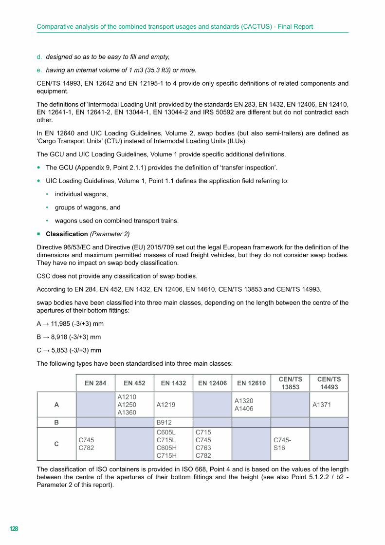
128
Comparative analysis of the combined transport usages and standards (CACTUS) - Final Report
d. designed so as to be easy to fill and empty,
e. having an internal volume of 1 m3 (35.3 ft3) or more.
CEN/TS 14993, EN 12642 and EN 12195-1 to 4 provide only specific definitions of related components and equipment.
The definitions of ‘Intermodal Loading Unit’ provided by the standards EN 283, EN 1432, EN 12406, EN 12410, EN 12641-1, EN 12641-2, EN 13044-1, EN 13044-2 and IRS 50592 are different but do not contradict each other.
In EN 12640 and UIC Loading Guidelines, Volume 2, swap bodies (but also semi-trailers) are defined as ‘Cargo Transport Units’ (CTU) instead of Intermodal Loading Units (ILUs).
The GCU and UIC Loading Guidelines, Volume 1 provide specific additional definitions.
y The GCU (Appendix 9, Point 2.1.1) provides the definition of ‘transfer inspection’.
y UIC Loading Guidelines, Volume 1, Point 1.1 defines the application field referring to:
• individual wagons,
• groups of wagons, and
• wagons used on combined transport trains.
� Classification (Parameter 2)
Directive 96/53/EC and Directive (EU) 2015/709 set out the legal European framework for the definition of the dimensions and maximum permitted masses of road freight vehicles, but they do not consider swap bodies. They have no impact on swap body classification.
CSC does not provide any classification of swap bodies.
According to EN 284, EN 452, EN 1432, EN 12406, EN 14610, CEN/TS 13853 and CEN/TS 14993,
swap bodies have been classified into three main classes, depending on the length between the centre of the apertures of their bottom fittings:
A → 11,985 (-3/+3) mm
B → 8,918 (-3/+3) mm
C → 5,853 (-3/+3) mm
The following types have been standardised into three main classes:
EN 284 EN 452 EN 1432 EN 12406 EN 12610 CEN/TS 13853
CEN/TS 14493
AA1210A1250A1360
A1219 A1320A1406 A1371
B B912
C C745C782
C605LC715LC605HC715H
C715C745C763C782
C745-S16
The classification of ISO containers is provided in ISO 668, Point 4 and is based on the values of the length between the centre of the apertures of their bottom fittings and the height (see also Point 5.1.2.2 / b2 - Parameter 2 of this report).
129
ILU-related topics
IRS 50692 and 50596-6 provide the conditions for uniform, safe and interoperable conveyance of ILUs loaded onto CT wagons. Within this framework, the following length codes are defined by IRS 50592 to facilitate the identification of swap bodies in terminals so as to ensure that they are loaded onto CT wagons in the correct position (loading diagram):
y Appendix H.1: Coding of ILU length for symmetrical dimensions: 20, 21, 22, 23, 24, 26, 27, 28, 29, 30, 31, 40, 42, 44, 45, 48, 49, 5 and 53.
y Appendix H.2: Coding of swap body length for asymmetrical dimensions: 60, 81, 82, 84, 85, 86, 91, 94, 95, 96, 97 and 98.
NB According to IRS 50592 and considering their longitudinal dimensions, ILUs are
y symmetrical when the values of their overhang are the same; and
y asymmetrical when the values of their overhang are different.
There are no contradictions between EN 283, EN 284, EN 452, EN 1432, EN 12406, EN 12410, TS/EN 13853, EN 14493, ISO 668 and IRS 50592 considering the different aims of the ILU classification provided by EN and ISO related standards and the ILU classification, via the length code, defined in IRS 50592.
UIC Loading Guidelines are not concerned with ILU classification; UIC Loading Guidelines, Volume 2, Point 9.0 refers to the length code, as defined by IRS 50592, when providing information on the content of the coding plates.
EN 13044-2 lists the length codes in accordance with IRS 50592 in Point 4.1, Table 1, but the list is not complete.
EN 13044-1 covers an identification system for swap bodies via their owner code and serial number, and it does not cover classification based on the dimensions of units.
EN 12640, EN 12641-1, EN 12641-2, EN 12642 and EN 12195-1 to 4 refer to ILU components/equipment and do not provide requirements on SB classification. EN 12640, EN 12641- 1, EN 12641-2 and EN 12642 only provide requirements for the classification of related items.
The GCU is not applicable to ILU classification.
� Dimensions (Parameter 3)
The provision of requirements on the dimensions of swap bodies is out of the scope of EN 12640, EN 12641-1, EN 12642- 1, EN 12641-2, EN 12642, EN 12195 1 to 5, EN 13044-1, EN 13044-2,
IRS 50596-6, IRS 50596-7, the GCU and UIC Loading Guidelines, Volumes 1 & 2.
Directive (EU) 2015/719 amending Directive 96/53/EC introduces the reference to swap bodies transported on semi-trailers up to a length of 45 ft into the European legal framework on freight road vehicles, increases the maximum length of semi-trailers, and sets the value of the maximum width of swap bodies at 2,600 mm (Appendix I, Point 1.2(b)).
Mandatory requirements on the dimensions of swap bodies, ISO containers and ILUs which can be conveyed on CT wagons are provided by:
y EN 284, EN 452, EN 1432, EN 12406, EN 12410, CEN/TS 15853 and CEN/TS 14993
y ISO 668
y IRS 50592
ISO 668 sets out:
y the external dimensions of standardised freight containers (Point 5.3, Table 2); and
y the internal dimensions of standardised freight containers.

130
Comparative analysis of the combined transport usages and standards (CACTUS) - Final Report
� External dimensions (Parameter 3.1)
EN 284 (Point 3, Table 1), EN 452 (Point 3, Table 1), EN 1432 (Point 4, Table 1), EN 12406 (Point 4,
Table 1), EN 12410 (Point 4, Table 1), EN 1432 (Point 4, Table 1), CEN/TS 13583 (Point 4, Table 1) and CEN/TS 14493 (Point 4, Table 1) provide the values of the external dimensions of EN standardised swap bodies.
As shown in the following table, some contradictions exist between EN 452, EN 1432 and the provisions of Directive 56/95/EC amended by Directive (EU) 2015/719.
EN 284 EN 452 EN 1432 EN 12406 EN 12610 CEN/TS13853
CEN/TS14493
A
Length (mm)A1210:L = 12,100 mmA1250:L = 12,500 mmA1360:L = 13,600 mm
A1219:L = 12,192 mm
A1320:L = 13,200 mmA1404:L =14,040 mm
A1371:L = 13,716 mm
Width2,550 mm 2,500 mm 2,600 mm 2,550 mm
Height value coherent with the CTPn resulting from the coding plate
B
LengthB912(L= 9,125 mm)
Width2,500 mm
Height value coherent with the CTPn resulting from the coding plate
C
Length
C745(L= 7,450 mm)C782(L= 7,820 mm)
C605L(L= 6,058 mm)C715L(L= 7,150 mm)C605H(L= 6,058 mm)C715H(L= 7,150 mm)
C715(L= 7,150 mm)C745(L= 7,450 mm)C763(L= 7,150 mm)C782(L= 7,150 mm)
C745-S16(L= 7,450 mm)
Width2,550 mm 2,500 mm 2,600 mm 2,550 mm
Height value coherent with the CTPn resulting from the codification plate
In particular EN 452 and EN 1432, making reference to Directive 85/3/EEC, limit the maximum width of Class A swap bodies and all types of swap tanks to 2,500 mm (a width of 2,600 mm is permitted for thermal swap bodies and refrigerated swap tanks).
Directive 85/3/EEC repealed by Directive 56/95/EC (then amended by Directive (EU) 2015/719) changed the value of the width of freight road vehicles from 2,500 mm to 2,550 mm (width = 2,600 mm is permitted for the superstructure of conditioned vehicles and conditioned containers or swap bodies transported by road vehicles).
IRS 50592 determines the dimensions of all existing ILU types (standardised or not) which can be conveyed on CT wagons without hindrance.
y Length value in accordance with the length code (IRS 50592, Appendix H).
y Max width:
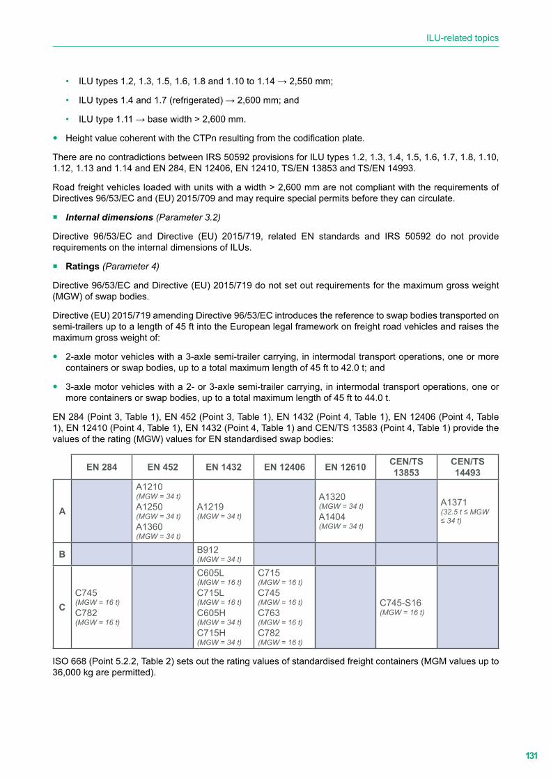
131
ILU-related topics
• ILU types 1.2, 1.3, 1.5, 1.6, 1.8 and 1.10 to 1.14 → 2,550 mm;
• ILU types 1.4 and 1.7 (refrigerated) → 2,600 mm; and
• ILU type 1.11 → base width > 2,600 mm.
y Height value coherent with the CTPn resulting from the codification plate.
There are no contradictions between IRS 50592 provisions for ILU types 1.2, 1.3, 1.4, 1.5, 1.6, 1.7, 1.8, 1.10, 1.12, 1.13 and 1.14 and EN 284, EN 12406, EN 12410, TS/EN 13853 and TS/EN 14993.
Road freight vehicles loaded with units with a width > 2,600 mm are not compliant with the requirements of Directives 96/53/EC and (EU) 2015/709 and may require special permits before they can circulate.
� Internal dimensions (Parameter 3.2)
Directive 96/53/EC and Directive (EU) 2015/719, related EN standards and IRS 50592 do not provide requirements on the internal dimensions of ILUs.
� Ratings (Parameter 4)
Directive 96/53/EC and Directive (EU) 2015/719 do not set out requirements for the maximum gross weight (MGW) of swap bodies.
Directive (EU) 2015/719 amending Directive 96/53/EC introduces the reference to swap bodies transported on semi-trailers up to a length of 45 ft into the European legal framework on freight road vehicles and raises the maximum gross weight of:
y 2-axle motor vehicles with a 3-axle semi-trailer carrying, in intermodal transport operations, one or more containers or swap bodies, up to a total maximum length of 45 ft to 42.0 t; and
y 3-axle motor vehicles with a 2- or 3-axle semi-trailer carrying, in intermodal transport operations, one or more containers or swap bodies, up to a total maximum length of 45 ft to 44.0 t.
EN 284 (Point 3, Table 1), EN 452 (Point 3, Table 1), EN 1432 (Point 4, Table 1), EN 12406 (Point 4, Table 1), EN 12410 (Point 4, Table 1), EN 1432 (Point 4, Table 1) and CEN/TS 13583 (Point 4, Table 1) provide the values of the rating (MGW) values for EN standardised swap bodies:
EN 284 EN 452 EN 1432 EN 12406 EN 12610 CEN/TS 13853
CEN/TS 14493
A
A1210(MGW = 34 t)A1250(MGW = 34 t)A1360(MGW = 34 t)
A1219(MGW = 34 t)
A1320(MGW = 34 t)A1404(MGW = 34 t)
A1371(32.5 t ≤ MGW ≤ 34 t)
B B912(MGW = 34 t)
CC745(MGW = 16 t)C782(MGW = 16 t)
C605L(MGW = 16 t)C715L(MGW = 16 t)C605H(MGW = 34 t)C715H(MGW = 34 t)
C715(MGW = 16 t)C745(MGW = 16 t)C763(MGW = 16 t)C782(MGW = 16 t)
C745-S16(MGW = 16 t)
ISO 668 (Point 5.2.2, Table 2) sets out the rating values of standardised freight containers (MGM values up to 36,000 kg are permitted).
132
Comparative analysis of the combined transport usages and standards (CACTUS) - Final Report
IRS 50592 refers to the above-mentioned EN and ISO standards (Point 1, Table 1) and allows (Point 5.1):
y ILUs with a length of 10 ft: MGM = 10,400 kg;
y ILUs with a length ≥ 20 ft: MGM = 36,000 kg; and
y ILU type 1.12: MGM ≥ 36,000 kg (only when carried on wagons equipped with reinforced restraining devices).
In contradiction with IRS 50592, MGM values higher than 36,000 kg are not permitted by related EN and ISO standards.
Road freight vehicles loaded with ILUs whose maximum gross mass value is higher than 36,000 kg are not compliant with the requirements of Directive 96/53/EC and Directive (EU) 2015/709 and may require special permits before they can circulate.
� Load transfer areas (Parameter 5)
Requirements on load transfer areas are out of the scope of Directive 96/53/EC, Directive (EU) 2015/709, CSC, EN 283, EN 12640, EN 12641-1, EN 12641-2, EN 12642, EN 13044-1, EN 13044-2, EN 12195-1 to 4, ISO 830, IRS 50596-6, IRS 50596-7, the GCU and UIC Loading Guidelines, Volumes 1 & 2.
EN 284, EN 452, EN 12406, EN 1432, EN 12410, CEN/TS 13853 and CEN/TS 14993 provide requirements on the dimensions and position of load transfer areas for the relevant types of swap bodies:
y EN 284, Point 5.3
y EN 452, Point 5.5
y EN 1432, Point 8.8.2 (equipping tank containers with load transfer areas is optional)
y EN 12410, Point 6.3
y CEN/TS 13853, Point 5.3.3.2
y CEN/TS 14493, Point 5.4.1.3
There are no requirements in EN 12406 and IRS 50592.
ISO 668, Appendix B provides requirements for load transfer areas:
y Minimum number (Point B.2.2)
y Position (Point B.2.3)
y Dimensions (Point B.2.4)
� Intermediate supports: dimensions and location (Parameter 6)
Requirements on intermediate support dimensions and location are out of the scope of Directive 96/53/EC, Directive (EU) 2015/709, CSC, EN 283, EN 284, EN 12406, CEN/TS 13853, CEN/TS 14993, EN 12640, EN 12641-1, EN 12641-2, EN 12642, EN 13044-1, EN 13044-2, EN 12195-1 to 4, ISO 668, ISO 830, IRS 50596-6, IRS 50596-7, the GCU and UIC Loading Guidelines, Volumes 1 & 2.
EN 452 and EN 12410 provide requirements on the dimensions and position of the intermediate supports for the relevant types of swap bodies:
y EN 452, Point 6 (optional)
y EN 12410, Point 9.2 (optional)
IRS 50592, Point 3 and Appendix G provide requirements for intermediate support areas for ILU types 1.5 to 1.14 (optional for length codes 40 to 53 and 91 to 98).

133
ILU-related topics
There are no requirements in EN 1432.
There are no contradictions between the requirements on this parameter provided by EN 452, EN 12410 and IRS 50592, but there is overlap between IRS 50592, Appendix G/Figure 31 and EN 452, Point 6/Figure 8.
� Gooseneck tunnel/steering tunnel: dimensions and location (Parameter 7)
Requirements on the gooseneck/steering tunnel are out of the scope of Directive 96/53/EC, Directive (EU) 2015/709, CSC, EN 12640, EN 12641-1, EN 12641-2, EN 12642, EN 13044-1, EN 13044.2, EN 12195-1 to 4, ISO 830, IRS 50596-6, IRS 50596-7, the GCU and UIC Loading Guidelines, Volumes 1 & 2.
EN 284, EN 452, EN 12406, EN 1432, EN 12406, EN 12410, CEN/TS 13853 and CEN/TS 14993
provide requirements on the dimensions and position of the gooseneck tunnel/steering tunnel for the relevant types of swap bodies:
y EN 284, Point 5.3
y EN 452, Point 5.3.4;
y EN 1432, Point 8.2.4
y EN 12406, Point 6.3
y EN 12410, Point 6.3
y CEN/TS 13853, Point 5.3.2
y CEN/TS 14493, Point 5.4.3
In ISO 668, Point 5.2.3, the equipment of containers with the gooseneck tunnel is:
y mandatory for 1EEE and 1AA; and
y optional for 1EE, 1AA, 1A and 1.AX.
Space required according to Appendix C, Figure C.1. Dimensions according to Appendix C, Table C.1.
There are no specific requirements in IRS 50592 which refers to EN 284, EN 452, EN1432, EN 12406 and EN 12410 for the relevant types.
� Upper and bottom fittings (Parameter 8)
Requirements on the location and technical characteristics of upper and bottom corner fittings are out of the scope of Directive 96/53/EC, Directive (EU) 2015/709, CSC, EN 12640, EN 12641-1, EN 12641-2, EN 12642, EN 13044-1, EN 13044-2, EN 12195-1 to 4, ISO 668, ISO 830, IRS 50596-6, IRS 50596-7, the GCU and UIC Loading Guidelines, Volumes 1 & 2.
� Upper (corner/intermediate) fittings: dimensions and location (Parameter 8.1)
Swap bodies compliant with EN 284, EN 452, EN 12406 and EN 12410 are not equipped with upper (corner/intermediate) fittings.
According to EN 1432, Point 9.1, equipping tank swap bodies with upper (corner/intermediate) fittings is optional.
Equipping swap bodies with upper (corner/intermediate) fittings is mandatory for stackable swap bodies compliant with CEN/TS 13853 (Point 5.2) and CEN/TS 14993 (Point 5.2).
According to ISO 1496-1 to 5, equipping ISO containers with upper (top) corner fittings is mandatory. Their location is defined in ISO 668, Appendix A (Figure A.1 and Table A.1).
ISO container types 1EEE and 1EE shall also be equipped with intermediate fittings.

134
Comparative analysis of the combined transport usages and standards (CACTUS) - Final Report
According to IRS 50592, equipping ILUs with upper (corner/intermediate) fittings is:
y optional for types 1.2, 1.4, 1.5, 1.7 (in contradiction with the corresponding EN standards), 1.10, 1.12, 1.14 (these types are not standardised in any EN standard) and 1.8 (tank swap bodies - as per EN 1432); and
y mandatory for types 1.3, 1.6 (stackable - as per CEN/TS13853, CEN/TS 14993 and ISO 1496-1 to 5) and 1.11 (this type is not standardised in any EN standard).
� Bottom (corner/intermediate) fittings: dimensions and location (Parameter 8.2)
EN 284, EN 452, EN 12406, EN 1432, EN 12406, EN 12410, CEN/TS 13853 and CEN/TS 14993 provide requirements on the dimensions and location of bottom (corner/intermediate) fittings for the relevant types of swap bodies:
y EN 284, Point 3
y EN 452, Point 3
y EN 1432, Point 8.1 (C715 swap bodies shall be equipped with intermediate bottom fittings)
y EN 12406, Point 6.1
y EN 12410, Point 6.1
y CEN/TS 13853, Point 4
y CEN/TS 14493, Point 4
ISO 668, Appendix A (Figure A.1 and Table A.1) sets out the location of bottom (corner/intermediate) fittings.
ISO container types 1EEE and 1EE shall also be equipped with intermediate fittings.
IRS 50592 sets out:
y for all ILU types and depending on the length code, the location of the bottom fittings (Appendix C.1); and
y requirements on the dimensions of the bottom fittings (Appendices D.1 and D.3).
There are no contradictions between related EN standards, ISO 668 and IRS 50592, but there is overlap between IRS 50592, Appendices D.1 and D.2 and the requirements on the dimensions of the bottom fittings provided by the above-mentioned EN standards.
� Technical requirements (Parameter 8.3)
There are no contradictions between EN standards, ISO 668 and IRS 50592.
According to IRS 5052 (Point 4), ILUs designed to be lifted from the top shall be provided with upper fittings compliant with ISO 1161 or have dimensions as per Appendix I (also known as simplified upper fittings).
Appendix I provides requirements on the dimensions of the simplified upper fittings, and the clearances to be kept.
� Grappler arm grooves: dimensions and location (Parameter 9)
Requirements on the dimensions and position of grappler arm grooves are out of the scope of Directive 96/53/EC, Directive (EU) 2015/709, CSC, EN 283, EN 12640, EN 12641-1, EN 12641-2, EN 12642, EN 12433-1, EN 12433-2, EN 12195-1 to 4, ISO 668, ISO 830, IRS 50592 (type 1.13),
IRS 50596-6, IRS 50596-7, the GCU and UIC Loading Guidelines, Volumes 1 & 2.
Requirements for grappler arm grooves are provided by EN 284, EN 452, EN 1432, EN 12406, EN 12410, CEN/TS 13853 and CEN/TS 14993 for the relevant types of swap bodies and by IRS 50592 for ILU types 1.2 to 1.12 and 1.14. Types 1.1 (ISO containers) and 1.13 (hybrid ILUs) are not equipped with grappler arm groves.

135
ILU-related topics
NB The term ‘hybrid ILU’, as identified in IRS 50592, means Intermodal Loading Units other than ISO containers equipped with upper fittings but without grappler arm grooves.
EN 284, EN 452, EN 1432, EN 12406, EN 12410, CEN/TS 13853, CEN/TS 14993 and IRS 50592 provide requirements on the dimensions and location of grappler arm grooves and their provision with end stops on either side to prevent the grappler arms from slipping out of the groove lifting areas when the relevant ILUs are longitudinally translated during transhipment.
y According to EN 284, Point 5.2, EN 12406, Point 6.1 and TS/EN 13853, Point 5.7.2:
• Where the length of the lifting area = 500 mm, equipping grappler arm grooves with end stops on either side is mandatory.
• Where the length of the lifting area = 850 mm, no end stop is required on either side.
y According to EN 452, Point 5.4.1, EN 12410, Point 6.1 and CEN/TS 14993, Point 5.8.1, equipping swap bodies with measures to prevent grappler arms from sliding is mandatory.
y According to EN 1432, Point 8.2.5, equipping grappler arm grooves with end stops on either side is mandatory.
IRS 50592 refers to EN 284 and EN 452 whose application is mandatory depending on the length of the ILU (Point 4).
In addition to the requirements provided by the above-mentioned standards, IRS 50592 requires the mandatory equipment of closed box ILUs with grappler arm grooves fitted with end stops on either side.
� Supporting legs: dimensions and location (Parameter 10)
Requirements on the dimensions and location of supporting legs are out of the scope of Directive 96/53/EC, Directive (EU) 2015/709, CSC, EN 283, EN 12640, EN 12641-1, EN 12641-2, EN 12642, EN 12433-1, EN 12433-2, EN 12195-1 to 4, ISO 668, ISO 830, IRS 50596-6, IRS 50596-
7, the GCU and UIC Loading Guidelines, Volumes 1 & 2.
Swap bodies compliant with EN 452, EN 12410 and CEN/TS 14993 are not equipped with supporting legs.
According to EN 284, Point 5.5, equipping Class C non-stackable swap bodies with supporting legs is mandatory.
The position of supporting legs is shown in Figure 7, which also specifies the mandatory values of clear width and clear height underneath a swap body on its supporting legs.
Annex B provides mandatory requirements on safety devices, mechanical strength, dimensions for interchangeability, and specific markings.
According to EN 1432, Point 8.2.4, equipping swap tank types C605L and C715L with supporting legs according to EN 284, Point 5.5 is mandatory.
EN 12406, Point 6.5 and CEN/TS 13853, Point 5.3.3.1 refer to EN 284, Point 5.5.
Equipping swap tank types C605L and C715L with supporting legs compliant with EN 284, Point 5.5 is mandatory.
No additional or specific requirements on supporting legs and no reference to EN or ISO standards are provided in IRS 50592.
� Fork-lift pockets: dimensions and location (Parameter 11)
Requirements on the dimensions and location of fork lift pockets are out of the scope of Directive 96/53/EC, Directive (EU) 2015/709, CSC, EN 12640, EN 12641-1, EN 12641-2, EN 12642, EN 12433-1, EN 12433-2, EN 12195-1 to 4, ISO 668, ISO 830, IRS 50596-6, IRS 50596-7, the GCU and UIC Loading Guidelines, Volumes 1 & 2.

136
Comparative analysis of the combined transport usages and standards (CACTUS) - Final Report
Swap bodies compliant with EN 452, EN 12410 and CEN/TS 14993 are not equipped with fork-lift pockets. There are no requirements in EN 12406 for Class C refrigerated swap bodies.
According to EN 284, Point 6.1 and CEN/TS 13853, Point 5.7.1, equipping Class C non-stackable swap bodies with fork-lift pockets used for handling them when loaded or unloaded is optional. If provided, they shall pass completely through the base structure of the swap body so that lifting devices can be inserted from either side.
Figure 8 shows the position and dimensions of fork-lift pockets (the eccentricity of the centre of gravity should not exceed 10% of the length of the swap body).
According to EN 1432, Point 5.5, equipping swap tanks with fork-lift pockets is prohibited (safety requirement).
No additional or specific requirements on fork-lift pockets and no reference to EN or ISO standards are provided in IRS 50592.
� Slinging apertures: dimensions and location (Parameter 12)
Requirements on the dimensions and location of slinging apertures are out of the scope of Directive 96/53/EC, Directive (EU) 2015/709, CSC, EN 12640, EN 12641-1, EN 12641-2, EN 12642, EN 12433-1, EN 12433-2, EN 12195-1 to 4, ISO 668, ISO 830, IRS 50596-6, IRS 50596-7, the GCU and UIC Loading Guidelines, Volumes 1 & 2.
As per:
y EN 284 (Point 5.1.2) and EN 12406 (Point 6.1), the slinging apertures of Class C non-stackable swap bodies are integrated into the bottom fittings. The dimensions of the slinging apertures are provided by Annex A which refers to, and overlaps with, ISO 1161.
y CEN/TS 13853 (Point 6.4.2) and CEN/TS 14993 (Point 5.2), the slinging apertures of stackable swap bodies are integrated into the intermediate bottom fittings; both documents refer, without overlap, to ISO 1161.
y EN 452 (Point 5.4.2) and EN 12410 (Point 6.2.2), Class A swap bodies shall be equipped with four slinging apertures positioned between the bottom fittings; the dimensions and location of these slinging apertures are provided by EN 452, Figures 7a and 7b (no overlap with ISO 1161).
y EN 1432 (Point 8.2.6), swap tanks shall be equipped with lateral openings for slinging according to EN 284, EN 452, ISO 1161 and UIC Leaflet 592-2 (repealed and partially migrated into IRS 50592).
y ISO 668, slinging apertures are integrated into the corner or intermediate bottom fittings.
In contradiction with related EN standards, according to IRS 50592, Point 4, equipping ILUs with slinging apertures positioned between the bottom fittings is optional.
If bottom fittings have such apertures, these shall comply with Appendix D, Points D.1 and D.2. As the drawings provided in Appendix D constitute a specific application of ISO 1661 to ILUs other than ISO containers (2,500 mm ≤ width ≤ 2,600 mm), they do not contradict the requirements provided by ISO 1161.
There is no overlap with related EN standards.
Slinging apertures not tested for use during transhipment shall be rendered inoperable.
� Front stop at the front-end wall (Parameter 13)
Requirements on the dimensions and location of the front stop at the front-end wall are out of the scope of Directive 96/53/EC, Directive (EU) 2015/709, CSC, EN 283, EN 12640, EN 12641-1, EN 12641-2, EN 12642, EN 12433-1, EN 12433-2, EN 12195-1 to 4, ISO 668, ISO 830, IRS 50596-6, IRS 50596-7, the GCU and UIC Loading Guidelines, Volumes 1 & 2.
According to EN 284, Point 5.4, equipping Class C swap bodies with a front stop at the front-end wall is mandatory. The standard provides requirements on its position and dimensions.
137
ILU-related topics
EN 12406, Point 6.4 refers to EN 284, Point 5.4.
No requirements are provided in EN 452, EN 12410, EN 1432, EN 12410, CEN/TS 13853, CEN/TS 14993 and IRS 50592.
� Front fittings in the front face of the ILU (Parameter 14)
Requirements on the dimensions and location of the front fittings in the front face of the ILU are out of the scope of Directive 96/53/EC, Directive (EU) 2015/709, CSC, EN 283, EN 12640, EN 12641- 1, EN 12641-2, EN 12642, EN 12433-1, EN 12433-2, EN 12195-1 to 4, ISO 668, ISO 830, IRS 50596-6, IRS 50596-7, the GCU and UIC Loading Guidelines, Volumes 1 & 2.
According to EN 452 (Point 5.3.1), EN 12406 (Point 9.1) and CEN/TS 14993 (Point 5.2), equipping Class A swap bodies with two front fittings is mandatory. The standard provides requirements for their dimensions and location on flat bottom swap bodies and on those with a base structure with longitudinal tunnel over the whole length.
No requirements are provided in EN 284, EN 12406, EN 1432, EN 12410, CEN/TS 13853 and IRS 50592.
� Body structure (Parameter 19)
Requirements related to Parameter 19 are out of the scope of Directive 96/53/EC, Directive (EU) 2015/709, CSC, EN 283, ISO 830, ISO 668, EN 12640, EN 12641-1, EN 12641-2, EN 12433-1, EN 12433-2, EN 12195-1 to 4, IRS 50596-6, IRS 50596-7, the GCU and UIC Loading Guidelines, Volumes 1 & 2.
EN 12642 defines the minimum requirements for standard vehicle bodies (Code L) and reinforced vehicle bodies (Code XL) and specifies appropriate tests (see also Parameters 109, 110 and 111).
It applies to the following types of body structure:
y Box type
y Drop side body with side and tail boards without tarpaulin cover
y Drop side body with side and tail boards with tarpaulin cover
y Curtainsider
A calculation for the complete system, consisting of front, rear and side walls, roof, and floor, is necessary for the entire structure, even if individual components have been taken from sample structures which have been calculated or tested with positive results before.
According to EN 284 (Point 4), EN 452 (Point 4), EN 12406 (Point 5.1.2) and EN 12410 (Point 5.1.2), swap bodies, as complete units, shall be able to withstand the loads and loadings specified in EN 283.
EN 1432 refers to UIC Leaflet 592-2 which was cancelled in 2014. The relevant requirements have been integrated into IRS 50592.
Points 8.2, 9.4 and 9.5 of this IRS provide the minimum requirements for the location of base structure attachments (reinforcements) or components such as the bottom side rail (optional) and doubler plates (optional).
According to Point 9.1, the top structure, when provided, can be equipped with top corner or intermediate fittings (compliant with ISO 1161).
The slanted transition between upper ISO dimensions to 2.5 mm frame width shall be in accordance with the relevant UIC Leaflet 592-2 requirements.
Concerning the requirements for the body structure of Class C stackable swap bodies, CEN/TS 13853 refers to EN 284.
Requirements for the body structure of Class A stackable swap bodies are provided by CEN/TS 14993, Point 5.4.1.1 and Appendix B.1.

138
Comparative analysis of the combined transport usages and standards (CACTUS) - Final Report
IRS 50592, Point 2 refers to EN 12642, Code XL requirements. In addition, the following requirements are provided:
Point 5.1: As ILUs can be conveyed in both directions at a maximum speed of 120 km/h, their superstructure (in particular, doors, shutters and collapsible sides) and their fittings shall withstand wind pressure (specifically, pressure increases and drops of minimum 1,500 Pa, as occur when traversing tunnels or passing another train).All external mobile parts of ILUs likely to exceed the railway loading gauge shall be equipped with a double locking system.
Point 5.11: The shape and dimensions of restraining devices on intermediate frames (fastenings, spigots, etc.) for loading units shall, when newly manufactured, meet the requirements of IRS 50571-4 (Point 2.3 and Appendix B) (see Normative references - page 3). The material from which restraining devices are fashioned shall, as a minimum, meet the strength requirements for materials in EN 10293, category E 260/450M.
� Tarpaulins (Parameter 20)
Requirements on tarpaulins are out of the scope of Directive 96/53/EC, Directive (EU) 2015/709, CSC, EN 283, EN 1432, EN 12406, EN 12410, CEN/TS 13853, CEN/TS 14993, ISO 830, ISO 668, EN 12640, EN 12642, EN 12433-1, EN 12433-2, EN 12195-1 to 4, IRS 50592 (types 1.3, 1.4, 1.6, 1.7 , 1.8, 1.9 and 1.14), IRS 50596-6, IRS 50596-7, the GCU and UIC Loading Guidelines, Volumes 1 & 2.
EN 12641-1 provides the following minimum requirements for the rigidity of tarpaulins used on semi- trailers for road and road/rail combined transport and of their attachments:
y Materials (Point 4.3)
y Construction (Point 4.4)
y Fixation of tarpaulins (Point 4.5)
EN 12641-2 provides minimum requirements for curtainsiders, in particular:
y Materials to be used for tarpaulins (Point 4.2)
y Tarpaulin reinforcements (Point 4.3)
y Belt hooks (Point 4.4)
y Vertical tensioning devices (Point 4.5.2)
y Horizontal tensioning devices (Point 4.5.3)
Tarpaulins compliant with this standard only work with a semi-trailer body structure according to EN 12642.
According to EN 284:
y Tarpaulins and their fitting devices used on drop sided Class C swap bodies shall be compliant with EN 12641-1 (Point 6.2.1).
y Tarpaulins used for curtainsiders shall be compliant with EN 12641-2 (Point 6.2.2).
No requirements and no reference are provided in EN 452 for Class A swap bodies.
The following requirements provided by IRS 50592, Point 5.4.2 are either not present in EN 452 or partially contradict EN 284:
Swap bodies with tarpaulins and tension belts:
y Tarpaulins and tension belts shall meet the strength and securing conditions defined in EN 12641.1 and EN 12641-2.
139
ILU-related topics
y Mandatory use of tensioning systems (ratchet and belts) tested as per EN 12641-2.
Swap bodies with side walls and tarpaulins:
y Tarpaulins shall meet the strength and securing conditions defined in EN 12641-1.
y Tension belts and locks shall be compliant with EN 12641-2.
Swap bodies with height-adjustable tarpaulins:
y Tarpaulins shall meet the strength and securing conditions defined in EN 12641-1.
y Tensioning closures shall be compliant with EN 12642-2 (maximum distance between two tensioners = 1,200 mm).
y Mandatory equipment of roof columns with a mechanical safety device to ensure that the roof does not exceed the maximum permitted height.
In all cases, elastic tarpaulin fastenings are not permitted.
� Ladders (Parameter 21)
Requirements on ladders are out of the scope of Directive 96/53/EC, Directive (EU) 2015/709, CSC, EN 283, EN 12640, EN 12641-1, EN 12641-2, EN 12642, EN 12433-1, EN 12433-2, EN 12195-1 to
4, ISO 668, ISO 830, IRS 50592 (types 1.9 and 1.14), IRS 50596-6, IRS 50596-7, the GCU and UIC Loading Guidelines, Volumes 1 & 2.
No requirements are provided in EN 284, EN 452, EN 12410, CEN/TS 13853, CEN/TS 14993 and IRS 50592 (types 1.2 to 18 and 1.10 to 1.13).
EN 1432, Point 9.7 sets out the value of the load to be supported by each ladder step. EN 12406, Point 7.4 provides requirements for ladder attachments.
� Walkways (Parameter 22)
Requirements on walkways are out of the scope of Directive 96/53/EC, EU Directive 2015/709, CSC, EN 283, EN 12640, EN 12641-1, EN 12641-2, EN 12642, EN 12433-1, EN 12433-2, EN 12195-1 to 4, ISO 668, ISO 830, IRS 50592 (types 1.9 and 1.14), IRS 50596-6, IRS 50596-7, the GCU and UIC Loading Guidelines, Volumes 1 & 2.
No requirements are provided in EN 284, EN 452, EN 12406, EN 12410, CEN/TS 13853,
CEN/TS 14993 and IRS 50592 (types 1.2 to 1.8 and 1.10 to 1.13).
EN 1432, Point 7.6 sets out the value of the loads to be withstood by walkways.
� Cargo securing (Parameter 24)
Requirements on the design of cargo securing devices are out of the scope of Directive 96/53/EC, Directive (EU) 2015/709, CSC, EN 283, EN 1432, EN12641-1, EN 12641-2, EN 12642, EN 12433-
1, EN 12433-2, EN 12195-1 to 4, ISO 668, ISO 830, IRS 50592 (types 1.4, 1.7, 1.8, 1.9), IRS 50596-6, IRS 50596-7 and the GCU.
� Anchor and lashing points (Parameter 24.1)
EN 12640 provides requirements on:
y single lashing point design (Point 4.2);
y multi-point lashing system design (Point 4.3);

140
Comparative analysis of the combined transport usages and standards (CACTUS) - Final Report
y number and layout of lashing points (Point 4.5);
y lashing points in the front wall (Point 4.6); and
y optional single lashing points or multi-point lashing systems (Point 4.7).
There are no contradictions or overlap between EN 12640, EN 284, CEN/TS 13853, CEN/TS 14993 and IRS 50592 (type 1.14).
As per:
y EN 284, Point 6.3, lashing points for cargo securing devices are mandatory for curtainsider swap bodies and optional for other types; when provided, they shall be compliant with EN 12640 and EN 12642.
y CEN/TS 13853, Point 5.7.3, equipping stackable swap bodies with lashing points is optional; when provided, lashing points for securing cargo shall be compliant with EN 12640.
y CEN/TS 14993, Point 5.8.2, equipping stackable swap bodies with lashing points is optional; when provided, lashing points for securing cargo shall be compliant with EN 452, Annex B (open point).
y IRS 50592, Points 5.7 and 5.8, flat ILUs with and without end walls (type 1.14) shall be equipped with lashing points in accordance with EN 12640.
No specific requirement on lashing points for cargo securing is provided in EN 452, EN 12406, EN 12410 and IRS 50592 (types 1.2, 1.3, 1.5, 1.6, 1.10, 1.11, 1.12 and 1.13) and there is no reference to EN 12640.
� Load restraint and lashing devices for cargo securing (Parameter 25)
Requirements on the design of lashing devices for cargo securing are out of the scope of Directive 96/53/EC, Directive (EU) 2015/709, CSC, EN 283, EN 284, EN 452, EN 1432, EN 12406, EN 12410, CEN/TS 13853, CEN/TS 13853, TS/EN 14993, EN12641-1, EN 12641-2, EN 12642, EN 12433-1, EN 12433-2, EN 12195-1 to 4, ISO 668, ISO 830, IRS 50592 (types 1.4, 1.7, 1.8 and 1.9), IRS 50596-6, IRS 50596-7 and the GCU.
EN 12195-1 applies to load restraining on ILUs designed for rail transport and provides:
y methods for calculations;
y test requirements; and
y acceleration values for cargo on ILUs during rail transport.
According to EN 12195-1, Table 3: Acceleration coefficients cx, cy and cz during rail transport
Securing inAcceleration coefficients
cx, longitudinallycy, transversely
cz, minimum vertically downSliding Tilting Sliding Tilting
Longitudinal direction 1.0 0.6 - 1.0 1.0
Transverse direction - - 0.5 0.7 1.0
EN 12195-2 to 4 apply to:
y web lashing made from man-made fibres (EN 12195-2);
y lashing chains (EN 12195-3); and
y lashing steel wire ropes (EN 12195−4).
For each of lashing devices, the EN standards:

141
ILU-related topics
y specify safety requirements and methods for testing; and
y deal with the significant hazards which could occur when web lashings are in use as intended and under conditions foreseen by the manufacturer.
EN 12640 refers to:
y EN 12195-2: Web lashing made from man-made fibres;
y EN 12195-3: Lashing chains; and
y EN 12195−4: Lashing steel wire ropes.
UIC Loading Guidelines, Volume 1, Point 1.3 sets out the value of the stresses arising during rail transport:
y Longitudinal acceleration = 1.0 g
y Lateral acceleration = 0.5 g
y Vertical acceleration = 0.3 g (in contradiction with EN 12195-1, Table 3)
UIC Loading Guidelines, Volume 2 refers to:
y EN 12195-1 for the identification of stresses during transport/relevant accelerations (Point 9.0.1) and for the determination of the friction coefficients (Point 0.6); and
y EN 12195-1 to 4 as applicable regulations for load securing (Point 9.0.1).
There is no contradiction between UIC Loading Guidelines, Volume 2 and EN 12195-1 to 4.
� Interface between road chassis and ILU (Parameter 26)
Requirements on the interface between the ILU and the road chassis are out of the scope of Directive 96/53/EC, Directive (EU) 2015/709, CSC, EN 283, EN 12640, EN 12641-1, EN 12641-2, EN 12642, EN 12433-1, EN 12433-2, EN 12195-1 to 4, ISO 668, ISO 830, IRS 50596-6, IRS 50596-7, the GCU and UIC Loading Guidelines, Volumes 1 & 2.
EN 452, Point 5.3 and Annex A provide the requirements for the interface between:
y Class A flat bottom swap bodies and Class A longitudinal tunnel swap bodies; and
y The vertical pin-type road chassis (Annex A, Point A.1) and the front horizontal pin-type road chassis (Annex A, Point A.2).
EN 12410, Point 9.1 refers to EN 452, Point 5.3 and Annex A.
No requirements on this parameter and no reference to EN 452 are provided in EN 284, EN 12406, EN 1432, CEN/TS 13853, CEN/TS 14993 and IRS 50592.
� Refrigeration and heating unit (Parameter 27)
Requirements on refrigeration/heating units are out of the scope of Directive 96/53/EC, Directive (EU) 2015/709, CSC, EN 283, EN 284, EN 452, EN 1432, CEN/TS 13853, CEN/TS 14993, EN 12640, EN 12641-1, EN 12641-2, EN 12642, EN 12433-1, EN 12433-2, EN 12195-1 to 4, ISO 668, ISO 830, IRS 50596-6, IRS 50596-7, the GCU and UIC Loading Guidelines, Volumes 1 & 2.
EN 12406 and EN 12410:
y provide requirements for refrigeration/heating units (Point 7) and electrical equipment (Point 8); and
y stipulate that refrigeration/heating units shall meet the Class C requirements of the ATP (Point 5.1.1).
IRS 50592 refers to EN 12406, EN 12410 and the ATP and requires in addition that the longitudinal dimensions and position of the refrigeration/heating equipment shall be considered when determining the length code of swap body types 1.4 and 1.7 (Point 5.2).
142
Comparative analysis of the combined transport usages and standards (CACTUS) - Final Report
� Thermal characteristics of the isothermal body (Parameter 28)
Requirements on the thermal characteristics of refrigerated ILUs are out of the scope of Directive 96/53/EC, Directive (EU) 2015/709, CSC, EN 283, EN 284, EN 452, EN 1432, CEN/TS 13853, CEN/TS 14993, EN 12640, EN 12641-1, EN 12641-2, EN 12642, EN 12433-1, EN 12433-2, EN 12195-1 to 4, ISO 668, ISO 830, IRS 50596-6, IRS 50596-7, the GCU and UIC Loading Guidelines, Volumes 1 & 2.
According to EN 12406 (Point 5.1.1) and EN 12410 (Point 5.1.1), the thermal characteristics of the isothermal body and the performance of the thermal device shall meet the Class C requirements of the ATP.
IRS 50592 refers to EN 12406, EN 12410 and the ATP. There are no contradictions with the requirements of IRS 50592, Point 5.2 for refrigerated ILU types 1.4 and 1.7.
� Devices for hanging cargo (Parameter 29)
Requirements on devices for hanging cargo inside refrigerated ILUs are out of the scope of Directive 96/53/EC, Directive (EU) 2015/709, CSC, EN 283, EN 284, EN 452, EN 1432, CEN/TS 13853, CEN/TS 14993, EN 12640, EN 12641-1, EN 12641-2, EN 12642, EN 12433-1, EN 12433-2, EN 12195-1 to 4, ISO 668, ISO 830, IRS 50596-6, IRS 50596-7, the GCU and UIC Loading Guidelines, Volumes 1 & 2.
EN 12406 (Point 5.2) and EN 12410 (Point 5.2) provide requirements on devices for hanging cargo inside refrigerated swap bodies (when provided).
No additional requirements are provided in IRS 50592, which refers to EN 12406 and EN 12410.
� Tank characteristics (Parameter 30)
Requirements on the characteristics of tanks equipping tank ILUs are out of the scope of Directive 96/53/EC, Directive (EU) 2015/709, CSC, EN 283, EN 284, EN 452, EN 12406, EN 12410,
CEN/TS 13853, CEN/TS 14993, EN 12640, EN 12641-1, EN 12641-2, EN 12642, EN 12433-1, EN 12433-2, EN 12195-1 to 4, ISO 668, ISO 830, IRS 50592 (types 1.2 to 1.6 and 1.8 to 1.14), IRS 50596-6, IRS 50596-7, the GCU and UIC Loading Guidelines, Volumes 1 & 2.
EN 1432 provides:
y mandatory requirements on:
• Tank securing (Point 6.1),
• Tank openings (Point 6.2),
• Pressure and vacuum relief devices (Point 6.3),
• Opening for inspection, cleaning, maintenance (Point 6.4),
• Gauging devices (Point 6.5), and
• Sealings (Point 6.6); and
y optional requirements on:
• Insulation (Point 7.1), and
• Heating and refrigeration (Point 7.2).
There are no contradictions with IRS 50592 (type 1.7), which refers to EN 1432 and to ADR/RID.
� Tests (Parameter 100)
Testing requirements are out of the scope of Directive 96/53/EC, Directive (EU) 2015/709, EN 13044-1, EN 13044-2, ISO 880, ISO 668, IRS 50596-6, IRS 50596-7, the GCU and UIC Loading Guidelines, Volumes 1 & 2.
CSC provides requirements for tests on containers covered by the convention. EN 283 provides basic testing requirements for Class A, B and C swap bodies.

143
ILU-related topics
EN 284 and EN 452 refer to EN 283 for testing requirements for Class C and A swap bodies.
EN 1432 refers to EN 283 for basic testing requirements and provides specific tests for swap tanks.
EN 12406 and EN 12410 452 refer to EN 283 for testing and provide specific tests for Class C and A refrigerated swap bodies.
CEN/TS 13853 and CEN/TS 14993 provide requirements on testing for stackable Class C and A swap bodies.
IRS 50592 refers to EN and ISO standards and CSC for test requirements and adds some requirements for tests on ILU typologies that are not yet covered by EN or ISO standards.
EN 12640, EN 12641-1, EN 12641-2 and EN 12195-1 to 4 provide specific requirements for ILU components and equipment.
EN 12642 provides testing requirements for ILU body structures.
� General (Parameter 101)
The strength of ILUs may be assessed through tests and/or calculations based on verifiable procedures (i.e. FEM).
No requirements are provided in the reference documents on the validation of CAD/FEM models used or on the documentation (i.e. digital 3D wagon drawings) to be provided by wagon manufacturers upon the request of ILU manufacturers.
After testing, ILUs shall not exhibit any permanent deformation or other changes which would make it impossible to use them in accordance with regulations; the dimensions required for handling, securing and transhipment shall be maintained.
� Stacking (Parameter 102)
Test requirements on the stacking ability of ILUs are out of the scope of Directive 96/53/EC, Directive (EU) 2015/709, EN 284, EN 452, EN 12406, EN 12410, EN 12640, EN 12641-1, EN 12640-2, EN 12642, EN 13044-1, EN 13044-2, EN 12195-1 to 4, ISO 880, ISO 668, IRS 50596-6, IRS 50596-7, the GCU and UIC Loading Guidelines, Volumes 1 & 2.
CSC, EN 1432, CEN/TS 13853 and CEN/TS 14993 provide requirements on testing the stacking ability of containers and swap bodies.
In all the above-mentioned documents the formula to define the value of the force to be applied in stacking tests is the same:
Force = (1.8 g x 0.25 x MAS) [kN]
where MAS is the value of the permitted superimposed stacking mass [kg].
The MAS value differs depending on the standard:
y CSC: MAS corresponds to the value indicated in the Safety Approval Plate.
y EN 1432: MAS corresponds to the mass of two laden swap tanks (34,000 kg).
y CEN/TS 133853: MAS = 192,000 kg (no correspondence between this value and mass of the superimposed swap bodies is provided in the document).
y CEN/TS 14993: MAS =
• 128,000 kg (mass of four laden swap bodies) when Test 1.A is performed;
• 64,000 kg (mass of two laden swap bodies) when Tests 1.B and 1.C are performed; and
• 32,000 kg (mass of one laden swap body) when Test 1.D is performed.
144
Comparative analysis of the combined transport usages and standards (CACTUS) - Final Report
NBTest 1A: Swap body supported by bottom corner fittings and test force applied to top corner fittings.Test 1B: Swap body supported by intermediate bottom fittings and test force applied to top corner fittings. Test
1C: Swap body supported by bottom corner fittings and test force applied to intermediate top fittings.Test 1D: Swap body supported by one pair of bottom corner fittings and one pair of supplementary fittings
spaced 11,985 mm apart and test force applied to top corner fittings.There are no requirements in EN 283 for testing the stacking ability of swap bodies. IRS 50592 (types 1.3 and 1.6) refers to CSC.
� Lifting (Parameter 103)
Test requirements on lifting are out of the scope of Directive 96/53/EC, Directive (EU) 2015/709, EN 12640, EN 12641-1, EN 12641-2, EN 12642, EN 13044-1, EN 13044-2, EN 12195-1 to 4, ISO 880, ISO 668, IRS 50596-6, IRS 50596-7, the GCU and UIC Loading Guidelines, Volumes 1 & 2.
CSC provides requirements on tests for lifting containers from their upper fittings. Compliance with CSC test requirements is mandatory for swap bodies fitted with a CSC Safety Approval Plate.
� Lifting from the grappler arm grooves (Parameter 103.1)
There are no contradictions between the test load values (combined mass of ILU + test load = 1.25 R for at least 5 minutes) and process set out in CSC, EN 283, EN 284, EN 452, EN 12406, EN 12410, TS/EN 13853, TS/EN 14993 and IRS 50592 (types 1.2 to 1.8, 1.10 to 1.12 and 1.14).
EN 1432 sets out the same value and process as per the above-mentioned standards, but adds a requirement on the compliance of tank swap bodies to UIC Leaflet 592-4 (for tank swap bodies for the transport of dangerous goods: combined mass of swap tank + test load = 2.0 R).
UIC Leaflet 592-4 has been cancelled and replaced by IRS 50592.
IRS 50592, Point 6.14.2 provides additional requirements to EN 283, CEN/TS 13583 and CEN/TS 14993 for testing the ability of ILU types 1.2, 1.3, 1.5, 1.6, 1.10, 1.11, 1.12 and 1.14 to be lifted from the grappler arm grooves when they are designed for the carriage of concentrated loads (Point 6.14.2).
The test load remains unchanged (combined mass of ILU + test load = 1.25 R for at least 5 minutes), but in this case the worst-case load scenario shall be tested on one third of the loading length.
� Lifting from the upper fittings (Parameter 103.2)
EN 284, EN 452, EN 12406 and EN 12410 standardised swap bodies and IRS 50592, types 1.2, 1.4. 1.5, 1.7, 1.9, 1.10 and 1.14 are not fitted with upper fittings.
EN 283 provides no requirements.
CSC (Annex II, Point A - i), EN 1432 (Point 10.5), CEN/TS 13853 (Point 6.3) and CEN/TS 14993
(Point 6.3) provide the following requirements on tests for lifting swap tanks and Class C and A stackable swap bodies:
y Combined mass of container + test load = 2.0 R for at least 5 minutes
y Lifting forces applied vertically
y Only for 1D and 1DX, angle between each lifting device and the horizontal: α = 60°
IRS 50592:
y Types 1.3, 1.6, 1.10, 1.11, 1.12 and 1.13: CSC applies.
y Type 11.8 (swap tanks): EN 1432 applies.
y Provides additional requirements to CSC for lifting tests on ILU types 1.3, 1.6, 1.10, 1.11, 1.12 and 1.13 suitable for the carriage of concentrated loads.
145
ILU-related topics
y Point 6.14.2 provides additional requirements to EN 283, CEN/TS 13583 and CEN/TS 14993 for testing the ability of ILU types 1.3, 1.5, 1.6, 1.10, 1.11, 1.12 and 1.14 to be lifted from the upper fittings when they are designed for the carriage of concentrated loads (Point 6.14.2).The test load remains unchanged (combined mass of ILU + test load = 2.0 R for at least 5 minutes), but in this case the worst-case load scenario shall be tested on one third of the loading length.
� Lifting from the bottom fittings (Parameter 103.3)
CSC provides requirements on containers to assess their ability to be lifted from the bottom fittings:
y Combined mass of container + test load = 2.0 R for at least 5 minutes
y Depending on container length (Lc):
Lc ≥ 12,000 mm → β = 30°
9,000 mm ≤ Lc ˂ 12,000 mm → β = 37°
6,000 mm ≤ Lc ˂ 9,000 mm → β = 45°
Lc ˂ 6,000 mm → β = 60°
where β is the angle between the direction of the lifting force and the horizontal.
EN 283, Point 5.2 provides requirements for swap bodies to assess their ability to be lifted from the bottom fittings:
y Combined mass of swap body + test load (uniformly distributed) = 1.50 R for at least 5 minutes
y Lifting forces shall be applied vertically
Appendix A to EN 283 sets out test requirements for swap bodies which are also submitted to CSC testing to receive the CSC Safety Approval Plate:
y Combined mass of swap body + test load (uniformly distributed) = 2.0 R applied for at least 5 minutes
y Depending on the class of the swap body:
Class A → β = 30°
Class B → β = 37°
Class C → β = 45°
where β is the angle between the direction of the lifting force and the horizontal.
There is no contradiction with CSC requirements; EN 283, Appendix A provides the same value for the test load and refers to Classes A, B and C rather than container length when providing the values of the angle between the direction of the lifting force and the horizontal (β).
EN 1432, Point 10.3 provides specific requirements for swap tanks:
y Dangerous goods: Combined mass of swap body + test load = 2.0 R and β = 45°
y Non-dangerous goods: Combined mass of swap body + test load = 1.5 R and β = 90°
where β is the angle between the direction of the lifting force and the horizontal.
The value of the test loads provided for swap tanks designed for the carriage of dangerous goods correspond to those set out in CSC.
The value of the test loads provided for swap tanks designed for the carriage of non-dangerous goods is lower than those set out in CSC. In this case, if CSC approval is requested, the values provided by the convention apply.

146
Comparative analysis of the combined transport usages and standards (CACTUS) - Final Report
CEN/TS 13853 provides specific requirements for Class C stackable swap bodies:
a. Point 6.4: Lifting from the four intermediate bottom fittingsCombined mass of swap body + test load (uniformly distributed) = 2.0 R and β = 45°
b. Point 6.5: Lifting from the four bottom fittingsCombined mass of swap body + test load (uniformly distributed) = 2.0 R and 37°≤ β ≤ 45°
where β is the angle between the direction of the lifting force and the horizontal.
There is no contradiction with CSC requirements; CEN/TS 13853 provides requirements for performing tests to prove the ability of stackable swap bodies type C 745 - S16 to be lifted from their bottom corner fittings and their bottom intermediate fittings.
CEN/TS 14993 provides specific requirements for Class A stackable swap bodies:
Point 6.4: Lifting from the four intermediate bottom fittings
Combined mass of swap body + test load (uniformly distributed) = 2.0 R and β = 30° Where β is the angle between the direction of the lifting force and the horizontal.
There is no contradiction with CSC requirements; CEN/TS 13853 provides requirements for performing tests to prove the ability of stackable swap bodies type A 1371 to be lifted from their bottom intermediate fittings.
EN 284, EN 452, EN 12406 and EN 12410 refer to EN 283.
IRS 50592 provides specific requirements for ILU types 1.2, 1.4, 1.5 and 1.7 to 1.14 and refers to CSC for stackable ILU types 1.3 and 1.6.
There are no contradictions between CSC, EN 283, EN 284, EN 452, EN 12406, EN 12410, CEN/TS 13853 and CEN/TS 14993.
There is no contradiction between IRS 50592, CSC and the above-mentioned EN standards.
� Lifting from the slinging apertures (Parameter 103.4)
As per Parameter 103.3.
� Lifting from the fork-lift pockets (Parameter 103.5)
CSC, Annex II (Point 1, clause B(i)) and EN 283, Point 5.4 provide requirements for this parameter. In contradiction with CSC, EN 283 sets out the combined mass of the swap body and the test load at 1.60 R (instead of 1.25 R as per CSC).
EN 284, EN 12406 and CEN/TS 13853 refer to EN 283.
Swap bodies compliant with EN 452, EN 12410, EN 1432 and CEN/TS 14993 are not fitted with fork- lift pockets.
The requirements provided in IRS 50592, Point 6.9 apply to ILU types 1.2, 1.3 and 1.10 to 1.14 (code lengths 20 to (29) and (60) only). There is no contradiction between IRS 50592 and the above- mentioned EN standards.
� External restraint (longitudinal) (Parameter 104)
The provision of requirements on this type of tests is out of the scope of Directive 96/53/EC, Directive (EU) 2015/709, EN 12640, EN 12641-1, EN 12641-2, EN 12642, EN 13044-1, EN 13044-2, EN 12195-1 to 4, ISO 880, ISO 668, IRS 50596-6, IRS 50596-7, the GCU and UIC Loading Guidelines, Volumes 1 & 2.
CSC, CEN/TS 13853 and CEN/TS 14993 provide requirements on static testing to be performed to prove the ability of ILUs to withstand longitudinal external restraint under dynamic conditions.
EN 283, EN 1432 and IRS 50592 (all types) provide requirements on both static and dynamic tests (as an alternative to static tests, dynamic tests may be performed).
EN 284, EN 452, EN 12406 and EN 12410 refer to EN 283.

147
ILU-related topics
� Static tests (Parameter 104.1)
There is no contradiction between the requirements provided by CSC, EN 283, EN 284, EN 452, EN 1432, EN 12406, EN 12410, CEN/TS 13853, CEN/TS 14993 and IRS 50592 (all types).
� Dynamic tests (Parameter 104.2)
There is no contradiction between EN 283, EN 284, EN 452, EN 12406, EN 12410 and IRS 59592 (types 1.2 to 1.7 and 1.9 to 1.14).
EN 1432, Point 10.7.2 and IRS 50592, Point 6.17.1 (type 1.8) provide requirements and a specific process for performing dynamic tests on swap tanks:
y Test load = 1.0 R (swap tank filled to a maximum of 97% of its volume capacity with water or another suitable fluid)
y Impact test carried out in both directions against a stationary wagon of 80 t: acceleration G = -2 g
y If the combined mass of the ILU and the filling fluid (R1) is lower than R, the test acceleration is to be changed as follows:
• g1 = (R/R1) x g and
• 2 g ≤ g1 ≤ 6 g
IRS 50592, Point 6.17.1 provides additional requirements for testing tank ILUs designed for the transport of dangerous goods:
y Test load = 1.0 R (swap tank filled to a maximum of 97% of its volume capacity with water or another suitable fluid)
y Impact test carried out in both directions against a stationary wagon of 80 t: acceleration G = -2 g
y If the combined mass of the ILU and the filling fluid (R1) is lower than R, the test acceleration is to be changed as follows:
• g1= (R/R1) x g and
• 3 g ≤ g1 ≤ 6 g
NB Impact tests on tank ILUs are not performed with the tank filled with dangerous goods. If the combination of the tare of the ILU and the filled mass is lower than the MGW for which the container was designed, the value of the maximum acceleration during the impact test shall be augmented and calculated according to the above-mentioned formula and the limit conditions changed from 2 g ≤ g1 ≤ 6 g to 3 g ≤ g1 ≤ 6 g.
The same requirements also apply to ILU types 1.10, 1.12 and 1.13 where tank ILUs are concerned.
RID, Point 7.1.3 refers to UIC Leaflets 592 (status at 1 October 2013, 2nd edition), 592-2 (status at 1 October 2004, 6th edition), 592-3 (status at 1 January 1998, 2nd edition) and 592-4 (status at 1 May 2007, 3rd edition) for the acceptance of tank containers. The next edition of RID will be updated to refer to IRS 50592.
� Internal restraint (lateral) (Parameter 106)
The provision of requirements on this type of test is out of the scope of Directive 96/53/EC, Directive (EU) 2015/709, CEN/TS 13853, CEN/TS 14993, EN 12640, EN 12641-1, EN 12640-2, EN 12642, EN 13044-1, EN 13044-2, EN 12195-1 to 4, ISO 880, ISO 668, IRS 50596-6, IRS 50596-7, the GCU and UIC Loading Guidelines, Volumes 1 & 2.
EN 1432 and IRS 50592 (types 1.8, 1.10, 1.12 and 1.13) provide:
y general requirements for testing to prove the ability of tank ILUs to withstand transverse internal restraint under dynamic conditions; and
y specific requirements for ILUs designed for the transport of dangerous goods.

148
Comparative analysis of the combined transport usages and standards (CACTUS) - Final Report
CSC, EN 283, EN 284, EN 452, EN 12406, EN 12410 and IRS 50592 (types 1.2 to 1.7 and 1.9, 1.10 and 1.14) do not provide any requirements.
� Rigidity (longitudinal) (Parameter 107)
The provision of requirements on such tests is out of the scope of Directive 96/53/EC, Directive (EU) 2015/709, EN 12640, EN 12641-1, EN 12641-2, EN 12642, EN 13044-1, EN 13044-2, EN 12195-1 to 4, ISO 880, ISO 668, IRS 50596-6, IRS 50596-7, the GCU and UIC Loading Guidelines, Volumes 1 & 2.
CEN/TS 13853 and CEN/TS 14993 provide specific requirements for tests to prove the ability of ILUs to withstand the longitudinal racking forces resulting from ship movement.
No test requirements related to this parameter are provided in CSC, EN 283, EN 284, EN 452, EN 1432, EN 12406, EN 12410 and IRS 50592.
� Rigidity (transverse) (Parameter 108)
The provision of requirements on such tests is out of the scope of Directive 96/53/EC, Directive (EU) 2015/709, EN 283 (no CSC swap bodies), EN 12640, 12641-1, 12641-2, EN 12642, EN 13044-1, EN 13044-2, EN 12195-1 to 4, ISO 880, ISO 668, IRS 50596-6, IRS 50596-7, the GCU and UIC Loading Guidelines, Volumes 1 & 2.
CSC, EN 283 (for swap bodies tested according to CSC requirements), CEN/TS 13853 and CEN/TS 14993 provide specific requirements for tests to prove the ability of ILUs to withstand the transverse racking forces resulting from ship movement.
No test requirements related to this parameter are provided by EN 284, EN 452, EN 1432, EN 12406, EN 12410 and IRS 50592.
� Strength of end walls (Parameter 109)
Requirements for testing the end walls of ILUs are out of the scope of Directive 96/53/EC, Directive (EU) 2015/709, EN 1432, EN 12640, EN 12641-1, EN 12641-2, EN 13044-1, EN 13044-2, EN 12195-1 to 4, IRS 50592 (types 1.8, 1.9 and 1.14), IRS 50596-6, IRS 50596-7, the GCU and UIC Loading Guidelines, Volumes 1 & 2.
EN 12642 specifies appropriate tests for standard (Code L) vehicle bodies (side walls, front and rear walls) and for reinforced (Code XL) vehicle bodies.
CSC, EN 283, CEN/TS 13853, CEN/TS 14993 and IRS 50592 (types 1.2 to 1.7 and 1.10 to 1.13) provide requirements for testing the relevant ILUs.
EN 284, EN 452, EN 12406 and EN 12410 refer to EN 283.
� Static tests (Parameter 109.1)
There are no contradictions between CSC, EN 283, EN 284, EN 452, EN 12406, EN 12410,
CEN/TS 13853 and CEN/TS 14993:
y Front and rear wall: Test load = 0.40 P uniformly distributed on the front and rear wall for at least 5 minutes = 0.4 Pg
According to IRS 50592, Table 2:
y Front wall: Test load = 0.40 P (or 0,50 P for ILUs compliant with EN 12642, Code XL)
y Rear wall: Test load = 0.40 P
The values of the test force provided by the above-mentioned reference documents are different to those provided in EN 12642:
y Front wall (Point 5.2.3):

149
ILU-related topics
• Code XL → Test load = 0.50 P (without max. limit, uniformly distributed and applied for at least 5 minutes)
• Code L → Test load = 0.40 P (without max. limit, uniformly distributed and applied for at least 5 minutes)
y Rear wall (Point 5.2.4):
• Code XL → Test load = 0.30 P (without max. limit, uniformly distributed and applied for at least 5 minutes)
• Code L → Test load = 0.25 P (without max. limit, uniformly distributed and applied for at least 5 minutes)
According to IRS 50592, Table 2:
y Front wall: Test load = 0.40 P (or 0.50 P for ILUs compliant with EN 12642, Code XL)
y Rear wall: Test load = 0.40 P
� Dynamic tests (Parameter 109.2)
There are no contradictions between CSC, EN 283, EN 284, EN 452, EN 12406, EN 12410,
TS/EN 13853, TS/EN 14993 and IRS 50592:
y Test load: 1.0 R
y Impact test carried out in both directions against a stationary wagon of 80 t: acceleration = -2 g
The values of the test acceleration provided by the above-mentioned reference documents are different from those provided in EN 12642:
y Front wall (Point 5.3.1 and Appendix B):Code XL → Acceleration = 0.80 g Code L → Not applicable
y Rear wall (Point 5.3.1 and Appendix B):gCode XL → Acceleration = 0.50 Code L → Not applicable
� Strength of side walls (Parameter 110)
Requirements for testing the end walls of ILUs are out of the scope of Directive 96/53/EC, Directive (EU) 2015/709, EN 1432, EN 12640, EN 12641-1, EN 12641-2, EN 13044-1, EN 13044-2, EN 12195-1 to 4, IRS 50592 (types 1.8, 1.9 and 1.14), IRS 50596-6, IRS 50596-7, the GCU and UIC Loading Guidelines, Volumes 1 & 2.
Since CSC also takes into account the forces resulting from ship movement, the value of the test load to apply to side walls fixed in CSC (0.60 P) is higher than the corresponding value provided by EN standards on general cargo and refrigerated ILUs (0.30 P).
There are no contradictions between the requirements provided in CSC, CEN/TS 13853, CEN/TS 14993 and the provisions provided in IRS 50592 for stackable ILUs.
There are no contradictions between the requirements provided in the relevant EN standards and the provisions provided in IRS 50592 for general cargo and refrigerated ILUs:
y Test load = 0.30 P (uniformly distributed and applied for at least 5 minutes)
According to IRS 50592, Table 2:
y Test load = 0.30 P (or 0.40 P for ILUs compliant with EN 12642, Code XL)
The values of the test parameters provided by the above-mentioned reference documents are different from those provided in EN 12642:
150
Comparative analysis of the combined transport usages and standards (CACTUS) - Final Report
y Static tests (Point 5.2.4 and Appendix A):
• Code XL → Test load = 0.40 P (without max. limit, uniformly distributed and applied for at least 5 minutes)
• Code L → Test load = 0.30 P (without max. limit, uniformly distributed and applied for at least 5 minutes)
y Dynamic tests (Point 5.3.1 and Appendix B):
• Code XL → Acceleration = 0.50 g
• Code L → Not applicable
� Strength of the ILU body structure (Parameter 111)
Requirements for testing the strength of ILU body structures are out of the scope of Directive 96/53/EC, Directive (EU) 2015/709, ISO 830, ISO 668, EN 12640, EN 12641-1, EN 12641-2, EN 14033-1, EN 13044-2, EN 12195-1 to 4, IRS 50596-6, IRS 50596-7, the GCU and UIC Loading Guidelines, Volumes 1 & 2.
EN 283 provides requirements for testing the body structure of Class A, B, and C and defines the values of the combined mass of swap body + test load, distinguishing between:
y Class A (not fitted with intermediate supports), Class B, Class C (2.00 R); and
y Class A swap bodies designed for conveyance with intermediate supports, in this case, the maximum permitted value of the force measured on the intermediate support is provided (1.50 R).
EN 284 and EN 452 refer to EN 283.
EN 12406 and EN 12410 refer to EN 283 and provide additional specific requirements for thermal swap bodies equipped with refrigeration/heating equipment.
CEN/TS 13853 and CEN/TS 14993 augment the value of the combined mass of swap body + test load to 1.80 R (the same value fixed in CSC for stacking) and provide a limit value of the deflection of the swap body under dynamic conditions.
EN 1432 sets the value of the combined mass of swap tank + test load at:
y 1.50 R for units designed for the transport of non-dangerous goods;
y 2.00 R for units designed for the transport of dangerous goods.
There are no contradictions between the requirements provided by the above-mentioned EN standards and the requirements provided in IRS 50592 for the corresponding ILU types.
In addition, IRS 50592 provides test requirements for testing the body structure of ILUs designed for the transport of concentrated loads.
Specific requirements are provided by IRS 50592 for testing the following components of intermediate frames (type 1.9):
y Spigots
y Link between wagon and frame
EN 12642 defines the process for:
y dynamic driving tests;
y static/airbag tests; and
y inclination tests, which apply to:
y box type body structures;
151
ILU-related topics
y drop side bodies with side and tail boards without tarpaulin cover;
y drop side bodies with side and tail boards with tarpaulin cover; and
y curtainsiders.
Ther are no contradictions between EN 12642 and the above-mentioned reference documents.
Requirements for testing the strength of ILU body structures are out of the scope of Directive 96/53/EC, Directive (EU) 2015/709, ISO 830, ISO 668, EN 12640, EN 12641-1, EN 12641-2, EN 14033-1, EN 13044-2, EN 12195-1 to 4, IRS 50596-6, IRS 50596-7, the GCU and UIC Loading Guidelines, Volumes 1 & 2.
� Strength of the roof (Parameter 112)
Requirements for testing the strength of ILU roofs are out of the scope of Directive 96/53/EC, Directive (EU) 2015/709, EN 1432, ISO 830, ISO 668, EN 12640, EN 12641-1, EN 12641-2,
EN 13044-1, EN 13044-2, EN 12642, EN 12195-1 to 4, IRS 50592 (types 1.9, 1.10 and 1.14), IRS 50596-6, IRS 50596-7, the GCU and UIC Loading Guidelines, Volumes 1 & 2.
EN 283 (non-CSC swap bodies), EN 284 and EN 452 do not provide any requirements for testing the roof of related swap bodies.
EN 12406 and EN 12410 provide additional requirements for refrigerated swap bodies fitted with devices for hanging cargo.
There are no contradictions between the requirements provided by CSC, EN 283 (CSC swap bodies) EN 12406, EN 12410, CEN/TS 13853 and CEN/TS 14993; while IRS 50592 provides a different value for the dimensions of the surface on which the test force is uniformly distributed (the value of the test force is the same).
� Testing tarpaulins (Parameter 113)
Requirements for tests on tarpaulins are out of the scope of Directive 96/53/EC, Directive (EU) 2015/709, CSC, EN 1432, EN 12406, EN 12410, CEN/TS 13853, CEN/TS 14993, ISO 830,
ISO 668, EN 12640, EN 12642, EN 13044-1, EN 13044-2, EN 12195-1 to 4, IRS 50592 (1.3, 1.4. 1.6, 1.7, 1.8, 1.9 and 1.14), IRS 50596-6, IRS 50596-7, the GCU and UIC Loading Guidelines, Volumes 1 & 2.
EN 283, EN 284 and 452 do not provide any requirements for testing tarpaulins.
EN 12641-1 provides specific requirements for testing the strength and attachment of tarpaulins used on swap bodies. In particular, Point 4.2 and Table 1 provide requirements on the quality of the materials used for manufacturing tarpaulins, which shall be such that the resulting product will ensure uniformity of performance.
EN 12641-2 provides specific requirements for testing the strength and attachment of tarpaulins used as curtainsiders on swap bodies. In particular:
y Point 4.2 and Table 1 provide requirements on the quality of the materials used for manufacturing tarpaulins used as curtainsiders, which shall be such that the resulting product will ensure uniformity of performance.
y Point 4.5.4.2 and Point 4.5.4.3 provide requirements and a method to perform static tests and dynamic tests to demonstrate the minimum strength of the vertical belt system.
IRS 50592, Point 2, Table 2 refers to EN 12641-1 and EN 12641-2 for test requirements on tarpaulins used on ILU types 1.2, 1.5 and 1.10 to 1.13. There are no contradictions or overlap between IRS 50592 and EN 12641-1 and 12641-2.
� Floor strength (Parameter 114)
Requirements on testing ILU floors are out of the scope of Directive 96/53/EC, Directive (EU) 2015/709, EN 1432, ISO 830, ISO 668, EN 12640, EN 12641-1, EN 12641-2, EN 12642, EN 13044-1, EN 13044-2, EN

152
Comparative analysis of the combined transport usages and standards (CACTUS) - Final Report
12195-1 to 4, IRS 50592 (1.3, 1.4, 1.6, 1.7, 1.8, 1.9 and 1.14), IRS 50596-6, IRS 50596-7, the GCU and UIC Loading Guidelines, Volumes 1 & 2.
The following reference documents provide different test load values. The following table summarises the relevant contradictions and overlaps:
Test load2,730 kg 2,200 kg
CSC, EN 283 (CSC swap bodies), CEN/TS 13853, CEN/TS 14993
andIRS 50592 (types 1.2 to 1.7 and 1.10 to 1.14)
EN 283 (non-CSC swap bodies), EN 284, EN 452, EN 12406 and EN 12410
� Testing the stability of ILUs standing on support legs (Parameter 115)
Requirements on testing the stability of related general cargo ILUs standing on their support legs are out of the scope of Directive 96/53/EC, Directive (EU) 2015/709, CSC, EN 452, EN 12410, CEN/TS 14993, ISO 830, ISO 668, EN 12640, EN 12641-1, EN 12641-2, EN 12642, EN 13044-1, EN 13044-2, EN 12195-1 to 4, IRS 50592 (1.5, 1.6, 1.7, 1.9, 1.12, 1.13 and 1.14), IRS 50596-6, IRS 50596-7, the GCU and UIC Loading Guidelines, Volumes 1 & 2.
EN 283 and EN 1432 provide requirements for testing the stability of related general cargo swap bodies and swap tanks standing on their support legs.
EN 284, EN 12406 and CEN/TS 13853 refer to EN 283.
IRS 50592 (type 1.8) refers to EN 1432.
No requirements on this parameter are provided in IRS 50592 (types 1.2, 1.3, 1.4, 1.10 and 1.11).
� Testing support legs (Parameter 116)
Requirements on testing support legs are out of the scope of Directive 96/53/EC, Directive (EU) 2015/709, CSC, EN 452, EN 12410, CEN/TS 14993, ISO 830, ISO 668, EN 12640, EN 12641-1,
EN 12641-2, EN 12642, EN 13044-1, EN 13044-2, EN 12195-1 to 4, IRS 50592 (types 1.5, 1.6, 1.7, 1.9, 1.12, 1.13 and 1.14), IRS 50596-6, IRS 50596-7, the GCU and UIC Loading Guidelines, Volumes 1 & 2.
EN 283 and EN 1432 provide requirements on testing swap body support legs. EN 284, EN 12406 and CEN/TS 13853 refer to EN 283.
IRS 50592 (type 1.8) refers to EN 1432.
No requirements on this parameter are provided in IRS 50592 (types 1.2, 1.3, 1.4, 1.10 and 1.11).
� Testing ladders (Parameter 117)
Requirements on testing the ladders are out of the scope of Directive 96/53/EC, Directive (EU) 2015/709, CSC, CEN/TS 13853, CEN/TS 14993, ISO 830, ISO 668, EN 12640, EN 12641-1,
EN 12641-2, EN 12642, EN 13044-1, EN 13044-2, EN 12195-1 to 4, IRS 50592 (types 1.9 and 1.14), IRS 50596-6, IRS 50596-7, the GCU and UIC Loading Guidelines, Volumes 1 & 2.
There are no contradiction between the requirements provided by EN 1432 and IRS 50592 (type 1.8) for swap ILUs.
No requirements on this parameter are provided in EN 283, EN 284, EN 452, EN 12406, EN 12410 and IRS 50592 (types 1.2 to 1.7 and 1.10 to 1.13).
� Testing walkways (Parameter 118)
153
ILU-related topics
Requirements on testing walkways are out of the scope of Directive 96/53/EC, Directive (EU) 2015/709, CSC, CEN/TS 13853, CEN/TS 14993, ISO 830, ISO 668, EN 12640, EN 12641-1, EN 12641-2, EN 12642, EN 13044-1, EN 13044-2, EN 12195-1 to 4, IRS 50592 (types 1.9 and 1.14), IRS 50596-6, IRS 50596-7, the GCU and UIC Loading Guidelines, Volumes 1 & 2.
There are no contradictions between the requirements provided by EN 1432 and IRS 50592 (type 1.8) for swap body ILUs.
No requirements on this parameter are provided in EN 283, EN 284, EN 452, EN 12406, EN 12410 and IRS 50592 (types 1.2 to 1.7 and 1.10 to 1.13).
� Pressure tests (Parameter 119)
Swap tanks to be used for the carriage of dangerous goods are subject to national and international requirements (ADR, RID, IMO/IMDG, UNMM “Orange book”, etc.).
According to EN 1432 and IRS 50592 (type 1.8), swap tanks shall be hydraulically tested. In addition, IRS 50592 provides the following test pressure values:
a. Dangerous goods = depends on the type of good (according to ADR/RID)
b. Non-dangerous goods = 0.3 bar
Pressure tests are out of the scope of the remaining reference documents.
� Testing shoring slots (Parameter 120)
there are no requirements on testing the shoring slots. The only reference is Annex D to ISO 1496- 1.
� Testing load transfer areas (Parameter 121)
EN 1432 provides requirements on tank swaps. There are no requirements in the remaining reference documents.
IRS 50592 (type 1.8) refers to EN 1432.
� Weatherproofness (Parameter 123)
EN 283, TS/EN 13853 and TS/EN 14993 provide requirements on tests to prove that swap bodies are weatherproof.
EN 284 and EN 452 refer to EN 283.
There are no requirements in the remaining reference documents.
� Testing lashing points for cargo securing (Parameter 124)
Test requirements and methods for testing lashing points for cargo security are specified by EN 12640.
EN 284, TS/EN 13853 and TS/EN 14993 refer to EN 12640.
There are no requirements in the remaining reference documents.
� Testing refrigeration/heating unit performance (Parameter 125)
As per EN 12406, EN 12410 and IRS 50592 (types 1.4 and 1.7), the performance of refrigeration/heating devices shall be checked in accordance with the requirements of the ATP.
There are no specific or additional requirements in the remaining reference documents.
� Testing refrigeration/heating unit attachments (Parameter 126)
EN 12406, EN 12410 and IRS 50592 (types 1.4 and 1.7) provide requirements for tests to prove the ability of refrigerated swap bodies attachments to withstand loading due to the mass of the refrigerating/heating device under dynamic conditions.
154
Comparative analysis of the combined transport usages and standards (CACTUS) - Final Report
IRS 50592 (types 1.4 and 1.7) refers to EN 12406 and EN 12410 for Class C and A refrigerated swap bodies and does not provide additional requirements.
There are no specific or additional requirements in the remaining reference documents.
� Testing the thermal characteristics of the isothermal body (Parameter 127)
As per EN 12406, EN 12410 and IRS 50592 (types 1.4 and 1.7), the characteristics of the isothermal body (global thermal transmission coefficient) shall meet the requirements of the ATP.
There are no specific or additional requirements in the remaining reference documents.
� Testing devices for hanging cargo (Parameter 128)
EN 12406 and EN 12410 provide requirements on tests to prove the ability of the roof structure of refrigerated swap bodies to withstand longitudinal restraint under dynamic conditions.
Static tests
Both standards provide the same test method but different values of the applied test force due to the different MGM of the two classes of refrigerated swap bodies:
EN 12406 → F = 26 kN
EN 12410 → F = 56 kN
Dynamic tests
Both standards require impact tests and provide the same requirements:
y Test load = 1.0 R (swap tank filled to a maximum of 97% of its volume capacity with water or another suitable fluid)
y Impact test carried out in both directions against a stationary wagon of 80 t: acceleration G = -2g
There are no specific or additional requirements in IRS 50592 or in the remaining reference documents.
� Concluding test (Parameter 129)
The purpose of this test is to verify that all components function correctly when ILUs are in use. During the test:
y all moving parts must function correctly (doors, side walls, tarpaulins, etc.); and
y the standard dimensions of the corner fittings used must fall within the permitted tolerance range.
The provision of requirements on the concluding test is out of the scope of Directive 96/53/EC, Directive (EU) 2015/709, EN 12640, EN 12641-1, EN 12641-2, EN 12642, EN 13044-1, EN 13044-2, EN 12195-1 to 4, ISO 880, ISO 668, IRS 50596-6, IRS 50596-7, the GCU and UIC Loading Guidelines, Volumes 1 & 2.
EN 283, EN 284, EN 452, EN 1432, EN 12406, EN 12410, CEN/TS 13853 and CEN/TS 14993 do not provide any specific requirements on the performance of the concluding test.
IRS 50592, Point 6.15 provides requirements on the performance of the concluding test.
� Design loadings (Parameter 200)
The basic parameters for the design of ILUs are:
y P = Maximum permissible payload;
y R = Permissible total mass of the ILU; and
y T = Tare mass.
155
ILU-related topics
The values of the test loads and the forces to apply to ILUs and their components when tests are performed are defined in the requirements provided for the above-mentioned parameters by IRS 50592, CSC, EN 283, EN 284, EN 452, EN 12406, EN 12410, CEN/TS 13853, CEN/TS 14993, EN 12641-1, EN 12641-2 and EN 12642.
EN 12640, and EN 12195-1 to 4 provide requirements for components (lashing points and lashing devices).
UIC Loading Guidelines, Volume 2 provides all the necessary measures for loading and securing goods, and is designed to guarantee operating safety and ensure damage-free conveyance of goods.
There are no contradictions between:
y IRS 50592, the above-mentioned standards and EN standards; and
y the applied forces and the conditions for cargo securing considered in UIC Loading Guidelines, Volume 2 and in EN 12195-1 to 4.
� Identification and markings (Parameter 300)
Identification and marking of ILUs and their components is out of the scope of Directive 96/53/EC, Directive (EU) 2015/709, EN 283, ISO 830, ISO 668, EN 12195-1 to 4, IRS 50596-6, IRS 50596-7, the GCU and UIC Loading Guidelines, Volume 1.
CSC, EN 284, EN 452, EN 12406, EN 12410, CEN/TS 13853, CEN/TS 14993, EN 13044-1, EN 13044-2, IRS 50592 and UIC Loading Guidelines, Volume 2 provide requirements for the identification and marking of ILUs other than semi-trailers.
EN 12640, EN 12641-1, EN 12641-2 and EN 12642 provide specific requirements for the identification of relevant ILU components.
� Identification (Parameter 300.1)
ILU identification is based on the owner code, the serial number, the check digit and the coding plates.
EN 13044-1 and EN 13044-2 provide a system for the identification of ILUs (4 letters, 6 digits + & check digit - ILU code) and requirements on the layout and content of coding plates.
There are no contradictions between EN 13044-1, EN 13044-2, IRS 50592, IRS 50596-6 and UIC Loading Guidelines, Volume 2 on semi-trailer identification systems.
EN 284, EN 452, EN 1432, EN 12406, EN 12410, CEN/TS 13853 and CEN/TS 14993 refer to
EN 13044-2 and UIC Leaflet 596-6, which has been updated and migrated into IRS 50596-6.
According to IRS 50596-6, IRS 50592 and UIC Loading Guidelines, Volume 2, coding plates affixed on:
y ILUs built before 1 July 2011 shall be compliant with UIC Leaflet 596-6, 5th edition of November 2006;
y ILUs built after 1 July 2011 shall be compliant with EN 13044-1 and EN 13044-2; and
y height-adjustable ILUs shall be compliant with Figure 7 (coding plates not yet integrated in EN 13044-2).
IRS 50592 provides the following requirements on the coding plates to be used for the identification of the following types of ILUs that are not yet standardised by CEN:
y ILUs able to carry more than 36,000 kg (heavy duty) shall be identified by a coding plate compliant with Point 5.1, Figure 2.
y ILUs which do not meet the requirements of IRS 50592 but can be conveyed on wagons compliant with IRS 50571-4 under bi- or multilateral agreements shall be identified by a coding plate compliant with Point 5.12, Figure 8.
y ILUs with maximum base width > 2,600 mm shall be identified by a coding plate compliant with Appendix A, Figure 15.

156
Comparative analysis of the combined transport usages and standards (CACTUS) - Final Report
� Operational markings (Parameter 300.2)
According to the related EN standards and the requirements set out in IRS 50592 for the different types, the application of the following markings is mandatory.
EN 284:
y Warning sign to indicate the maximum front-axle load of a fork-lift truck which an empty swap body resting on its supporting legs can resist without tipping when being loaded or unloaded from one end.
y Warning sign: “Secure supporting legs by both safety devices”.
y Grappler arm lifting areas (including the safety lip) marking.
EN 1432 and IRS 50592 (type 1.8):
y RID/ADR markings for swap body ILUs designed for the carriage of dangerous goods.
EN 12406, EN 12410 and IRS 50592 (types 1.4 and 1.7):
y ATP markings for refrigerated ILUs.
CEN/TS 13853 and CEN/TS 14993:
y Maximum tare and gross mass marking (only for ILUs compliant with CEN/TS 13853).
y Warning sign for prohibited stacking configurations.
y Warning sign illustrating risk of overturning (only for ILUs compliant with CEN/TS 13853).
y Warning electricity (overlap: the same marking is required by EN 13044-2).
EN 13044-2:
y Maximum gross and tare masses (only for swap bodies which can be transported on inland waterways and sea).
y Warning electricity.
y Warning sign for prohibited stacking configurations (reference to CEN/TS 13853).
IRS 50592:
y Horizontal marking for ILUs with height-adjustable roof and two different coding plates (Point 5.10, Figure 7).
y Type marking of ILUs.
y Marking for ILUs with special equipment for carrying loads subject to compacting.
y Intermediate support surface marking.
y Marking for ILUs designed for the carriage of concentrated loads.
y Marking for ILUs designed for the carriage of sheet metal coils or similar concentrated loads.
y Marking for the identification of securing devices to be used during rail transport.
y Marking for ILUs (code lengths 40 to 53 and 91 to 98) suitable for conveyance on all types of pocket wagons.
y Marking for ILUs (code lengths 40 to 53 and 91 to 98) not suitable for conveyance on pocket wagons.
y Marking for ILUs (code lengths 40 to 53 and 91 to 98) suitable for conveyance on pocket wagons with active intermediary supports only.

157
ILU-related topics
UIC Loading Guidelines, Volumes 1 & 2 represent the UIC code of practice for the loading and securing of goods on railway wagons. They are intended for the operating staff of railway undertakings and ensure the safety and damage-free conveyance of goods in rail transport.
UIC Loading Guidelines, Volume 2 provides explanations of the meaning and use of all the markings which are relevant for the safety of ILU rail transport and which must be known by operating staff.
The guidelines are updated annually to ensure that all new markings provided in the relevant documents have been taken into account.
� Maintenance (Parameter 400)
The provision of requirements on ILU maintenance is out of the scope of Directive 96/53/EC, Directive (EU) 2015/709, ISO 830, ISO 668, EN 283, EN 13044-1, EN 13044-2, EN 12195-1 to 4, IRS 50596-6, IRS 50596-7, the GCU and UIC Loading Guidelines, Volume 1.
According to CSC, the owner is responsible for maintaining containers in good condition and arranging for their inspection at regular intervals to check for defects and potential dangers. This responsibility is transferred to the lessee if the container is leased. Two types of inspection can be carried out: Periodic Examination Scheme (PES) and Approved Continuous Examination Programme (ACEP).
Periodic Examination Schemes (PES)
Under a periodic examination scheme, a container must be first examined within five years of the date on which it was manufactured and thereafter within 30 months of the date of the last examination. The date before which a container should next be examined must be clearly marked on the Safety Approval Plate of the container or as close as practicable to it.
Approved Continuous Examination Programmes (ACEP)
Under an approved continuous examination programme, a container must undergo thorough examinations in connection with any major repair, refurbishment or on-hire/off-hire interchange. Frequent routine operating inspections should also be carried out to detect any damage or deterioration that might necessitate repair or other corrective action.
The Convention:
y states that a container should be subjected to examination and inspection during normal operation; two types of examinations are foreseen:
a. thorough examinations conducted in connection with major repair, refurbishment or on-hire/off- hire interchange and
b. routine operating inspections performed with the object of detecting any damage or deterioration which may necessitate corrective action; and
y defines the list of factors to be considered in the examinations.
In contradiction with CSC, IRS 50592 stipulates that the owner is always responsible for the good condition and maintenance of their ILUs. IRS 50592 does not provide any requirements on maintenance or examination procedures nor any list of acceptable irregularities and defects.
For the examination criteria, Appendix 9 of the GCU applies. Annex 1 (Points 7.5, 7.7 and 7.8) of the appendix sets out:
y the binding provisions governing the technical condition of ILUs loaded on CT wagons exchanged between two or more railway undertakings, as established during
• a technical inspection upon handover conducted by the transferor RU or
• a technical inspection upon acceptance conducted by the transferee RU;

158
Comparative analysis of the combined transport usages and standards (CACTUS) - Final Report
y the catalogue of irregularities, where appropriate with criteria and indications to facilitate detection; and
y the action to be taken by qualified RU inspectors.
IRS 50592 stipulates that the owner is always responsible for the good condition and maintenance of their ILUs, but does not provide any requirements on maintenance and examination procedures, or revision periodicity.
According to UIC Loading Guidelines, Volume 2, Point 9.1 for swap bodies and Point 9.1.2 for special swap bodies, the date of the next overhaul is indicated on the CSC plate or next to it for ILUs to be examined under a periodic examination scheme (PES) or is not indicated if ILUs are monitored permanently under an approved continuous examination plan (ACEP).
EN 284, EN 452, EN 1432, EN 12406, EN 12410, CEN/TS 13853 and CEN/TS 14993 do not provide any requirements on this parameter.
EN 12640 (lashing points) and EN 12642 (body structure) oblige manufacturers to provide users with instructions for inspecting the condition of the relevant swap body parts.
� Operational control (Parameter 500)
Operational control is based on the documents provided to the operating staff involved in the transport of ILUs to ensure their safe transport, including:
y instructions for use of ILUs and their equipment;
y conditions for the technical transfer inspection of wagons and ILUs, in particular the catalogue of irregularities and the actions to be taken; and
y guidelines on loading and securing ILUs.
The provision of documents on operational control is out of the scope of Directive 96/53/EC, Directive (EU) 2015/709, CSC, EN 283, EN 13044-1, EN 13044-2, ISO 830, ISO 668, IRS 50596-6, IRS 50596-7 and UIC Loading Guidelines, Volume 1.
Instructions for use
No requirements on instructions for use of ILUs are provided in EN 284, EN 452, EN 1432, EN 12406, EN 12410, CEN/TS 13853, CEN/TS 14993 and IRS 50592.
According to EN 12195-1, instructions for the use of load securing devices shall be provided. EN 12195-2, EN 12195-3 and EN 12195-4 oblige manufacturers to provide instructions for the use of web lashing devices, lashing chains and lashing steel wire ropes (Appendix B to each standard).
Conditions for the technical transfer inspection of wagons
There are no requirements in EN 284, EN 452, EN 1432, EN 12406, EN 12410, CEN/TS 13853, CEN/TS 14993 and IRS 50592.
The GCU, including its appendices, sets out the conditions for the provision of wagons for use as a means of transport by RUs in national and international traffic within the scope of application of the COTIF in force.
Each RU shall carry out all the safety-related inspections referred to in Appendix 9 “Conditions for the technical transfer inspection of wagons”.
Appendix 9, Annex 1 provides the catalogue of irregularities and the actions to be taken by qualified RU inspectors. The irregularities concerning swap bodies loaded on CT carrier wagons are referenced in Points 7.5.1, 7.5.2, 7.5.4 to 7.5.7, 7.6, 7.7.1, 7.7.9 and 7.8.1 to 7.8.4.
Loading and securing guidelines
According to the GCU, Article 29, RUs shall ensure that shippers comply with the UIC Loading Guidelines in force.
159
ILU-related topics
UIC Loading Guidelines, Volume 2 provides all the necessary measures for loading and securing goods, and is designed to guarantee operating safety and ensure damage-free conveyance of goods.
i. Measures for loading swap bodies
UIC Loading Guidelines, Volume 2 (Loading methods 9.1, 9.1.1, 9.1.2 and 9.1.3) provides requirements for the appropriate loading of swap bodies on compatible CT carrier wagons.
Loading method 9.0.1 provides guidelines and requirements for loading cargo on swap bodies (stresses during transit acceleration in accordance with EN 12195-1, Table 3) and measures to ensure the stability of the cargo.
ii. Measures for securing swap bodies
UIC Loading Guidelines, Volume 2 (Loading methods 9.1, 9.1.1, 9.1.2 and 9.1.3) provides requirements for securing swap bodies loaded on compatible CT carrier wagons through an appropriate use of their equipment.
� Certification (Parameter 600)
There are no contradictions between EN 284, EN 452, EN 1432, EN 12406, EN 12410, CEN/TS 13853, CEN/TS 14993, EN 12642, EN 13044-1, IRS 50596-6 and IRS 50596-7.
The registration of the owner code (EN 13044-1) is carried out by UIRR.
Concerning swap bodies, IRS 50596-6 specifies that codification, the approval of ILUs other than semi-trailers and the delivery of coding plates is carried out by bodies recognised by UIC and listed in IRS 59596-6 (more details available in the following points on Parameters 600.1, 600.2 and 600.3).
According to EN 12642, Appendix C, the test certificate of body structures compliant with EN 12642 shall be issued and signed by the subject responsible for the tests.
The layout and content of the manufacturer’s certificate are provided by EN 12195-3, Point 9 (Lashing chains) and EN 12195-4, Point 9 (Lashing steel wire ropes). The subject in charge of certification is not identified.
No requirements on certification are provided in IRS 12195-2
� Codification (Parameter 600.1)
For this parameter, see also Chapter 3 of this document.
The provision of requirements on ILU coding is out of the scope of Directive 96/53/EC, Directive (EU) 2015/709, CSC, EN 283, EN 12640, EN 12641-1, EN 12641-2, EN 12642, EN 12195-1 to 4, EN 13044-1 and the GCU.
IRS 50596-6 defines the criteria for coding ILUs other than semi-trailers. IRS 50592 and IRS 50596-7 refer to IRS 50596-6.
EN 284, EN 452, EN 1432, EN 12406 EN 12410, CEN/TS 13853, CEN/TS 14993, EN 13044-2 and UIC Loading Guidelines, Volume 2 refer to UIC Leaflet 596-6, which has been updated and migrated into IRS 50596-6.
� ILU approval (Parameter 600.2)
� Coding plate delivery (Parameter 600.3)
EN 284, EN 452, EN 1432, EN 12406, EN 12410, TES/EN 13853 and TS/EN 14993 do not provide any requirements on the coding process of ILUs other than semi-trailers and ISO containers.
EN 13044-2 applies to the allocation of the codification plate and the application of operational markings to swap bodies intended for use in the international exchange of goods and for their conveyance by road and rail.
IRS 50592 refers to IRS 50596-6 for the codification process of ILUs other than semi-trailers and provides procedures for:
y the approval of ILU prototypes or prototype variants; and
y the codification of series ILUs.

160
Comparative analysis of the combined transport usages and standards (CACTUS) - Final Report
IRS 50596-7 provides the requirements for bodies to be recognised by UIC for performing type approval, for granting ILU codification and for delivering codification plates. In particular, it details the competencies of bodies recognised by UIC to perform one or more of the following tasks:
y ILU type approval (list and identification numbers)
y ILU codification
y Delivery of coding plates
Contradictions exist between EN 13044-2, IRS 50592, IRS 50596-6 and IRS 50596-7.
EN 13044-2 refers to UIC Leaflets 596-5 and 596-6. These two documents have been updated and migrated into IRS 50596-5 and IRS 50596-6, respectively. In addition, IRS 50596-7 provides the requirements for bodies which are recognised by UIC for granting codification, swap body approval and coding plate delivering.
According to IRS 50596-6:
y Codification is granted by a body which is recognised by UIC and listed in Appendix H.1.
y Swap body approval and coding plate delivery are carried out by a body agreed by UIC and listed in Appendix H.1.
According to IRS 50596-7, Point 4.2, the approval and coding of swap bodies built after 1 July 2011 and the delivery of coding plates can be carried out by:
y National Safety Authorities,
y infrastructure managers,
y freight railway undertakings, and
y delegated bodies
The list of bodies recognised by UIC to grant codification (Table 1), to approve swap bodies (Table 2) and to deliver coding plates (Table 2) is provided by IRS 50596-6, Appendix H.1.
Appendix H.1 to IRS 50596-6 can be obtained free-of-charge via the following link:https://uic.org/IMG/pdf/irs_50596x6_appendix_h1_26_03_2020_en.pdf
RS 50596-6, Appendix H.2 provides the complete lists and the identification number (national number) of bodies which have been recognised by UIC Leaflet 596-5 (5th edition) for granting codification and delivering plates before 1 July 2011.
Before 1 July 2011, codification was granted by RUs, IMs or CT companies agreed by UIC and identified by a national number. The list of the recognised entities and their corresponding national numbers is the subject of Appendix H.2.
Appendix H.2 can be obtained free-of-charge via the following link:https://uic.org/rail-system/rolling-stock/#UIC-leaflets-on-Combined-Transport
5.1.3.3. Potential areas of improvement, cross-referencing and harmonisation needs
Based on the results of the dry and comparative analysis (see Point 5.1.3.2), the following areas were identified as requiring improvement and harmonisation.
The UIC and UIRR recommendations for better harmonisation and integration of the requirements for the design, testing and transport of ILUs other than ISO containers and semi-trailers in combined transport, taking into account their compatibility with carrying wagons and the interoperability of combined transport trains and their interface with the railway infrastructure, are the subject of Chapter 7 of this report.
161
ILU-related topics
H. Updating EN standards, IRSs and other relevant technical documents
While semi-trailers for vertical transhipment are standardised by EN 16973 and, for aspects closely related to rail transport, covered by IRS 50596-5, swap bodies are subject to much more extensive reference technical documentation.
Requirements for the standardisation of swap bodies are provided by seven CEN documents and by IRS 50592. In particular, EN 284 and EN 452 (Class C and A general purpose swap bodies), EN 1432 (tank swap bodies), EN 12406 and EN 12410 (Class C and A refrigerated swap bodies), CEN/TS 13853 and CEN/TS 14993 provide specifications for the uniform design and construction of Class C and A stackable swap bodies.
EN 283 provides the requirements for the tests to be carried out on swap bodies to prove that they can withstand the stresses to which they are subjected during transport. Requirements for the testing of specific types of swap bodies, such as tank swap bodies and refrigerated swap bodies, are provided in the relevant EN standards and technical specifications (CEN/TS).
The international Convention for Safe Containers (CSC) applies when required by the above- mentioned standards or at the customer’s request.
IRS 50592 considers both EN standardised swap bodies and other types of non-standardised ILUs, including:
� ILUs whose dimensions allow them to be coded according to IRS 50596-6;
� ILUs with a base width > 2,600 mm;
� ILUs that due to their dimensions or maximum gross mass may not be freely loaded onto CT wagons marked with wagon compatibility code C;
� hybrid ILUs (fitted with upper corner fittings but no grab handling grooves); and
� flat ILUs.
As IRS 50592 is focused on railway operation, ILUs are classified according to a length code in order to facilitate their transhipment from road to rail and to make better use of the loading length of the train.
Regarding ILU test requirements, IRS 50592 refers to EN 283, to the relevant specific requirements set out in the above-mentioned EN standards, and to CSC.
Additional requirements are provided for non-EN or ISO standardised ILUs (ILUs for the carriage of concentrated loads).
The current versions of some EN standards were published more than twenty years ago and have not been revised since.
The structure of the first EN standards to be published is different from that of standards published later and, in any case, does not correspond to the consolidated structure of ISO standards on freight containers, which provide all the requirements, including those related to the tests to prove that the type of container concerned is capable of withstanding the stresses to which it is subjected during transport.
The definitions in some EN standards have been defined by different CEN committees and are sometimes different.
Cross-references between standards are not used in a comprehensive way and some cross- references to standards and technical documents that have since been amended have not been updated.
No EN standard on flat swap bodies has been published.
The revision of the following technical documents is necessary.
162
Comparative analysis of the combined transport usages and standards (CACTUS) - Final Report
I. Maintenance
In addition to railway undertakings and infrastructure managers, the transport of ILUs by rail, road, maritime and internal waterways involves several actors, including:
� road and maritime carriers: enterprises that carry out transport operations pursuant to a contract of carriage;
� consignors: enterprises that deliver goods;
� consignees: natural or legal persons receiving goods;
� loaders: enterprises that load packaged goods onto ILUs, or which load ILUs onto wagons;
� unloaders: enterprises that remove ILUs from wagons, or unload packaged goods from ILUs;
� fillers: enterprises that load goods into tank ILUs; and
� unfillers: enterprises that remove goods from tank ILUs.
Although Directive (EU) 2016/798 of the European Parliament (Safety Directive) stipulates that, without prejudice to the responsibilities of railway undertakings and infrastructure managers, entities in charge of maintenance, manufacturers, maintenance suppliers, keepers, service providers, contracting entities, carriers, consignors, consignees, loaders, unloaders, fillers and unfillers, shall ensure that subsystems, accessories, equipment and services supplied by them comply with specified requirements and conditions for use so that they can be safely operated by the railway undertaking and/or the infrastructure manager concerned, the European legal framework does not define the entity responsible for ILU maintenance nor stipulate any obligation of consignor, consignee, loaders (fillers) or unloaders (unfillers) to perform inspections.
Similarly to the CSC for freight containers, the following actions should be implemented:
� Unambiguous definition of the entity responsible for ILU maintenance.
� Definition of a clear maintenance scheme.
� Definition of a catalogue of irregularities and possible damages.
� Publication of guidelines for the evaluation and the action to be taken in case of irregularities and damages found during inspections made:
y before packaging goods onto ILUs;
y before loading ILUs on CT wagons;
y during technical inspections of trains;
y after having removed ILUs from wagons; and
y after having unloaded goods from ILUs.
J. Guide to the application of the relevant CT documents
The analysis demonstrates that the reference documentation on combined transport (wagons, ILUs, lines, coding, operation, etc.) is extensive and highly detailed. An Application Guide is therefore necessary to provide information on how to apply the related legal framework, ISO standards, EN standards and UIC technical documents (IRSs and Loading Guidelines) to combined transport.
The aim of the Application Guide is to facilitate CT stakeholder understanding and application of current relevant reference documents, by explaining how CT wagons, CT lines and ILUs must be built and assessed in order to comply with the essential requirements provided by the above- mentioned documentation.
To meet stakeholder needs as effectively as possible, the Application Guide shall provide users with a complete overview of the content of the reference documents and explain how they must fulfil the requirements, managing them from a technical point of view.
163
ILU-related topics
Consequently, the guide should consist of a general part, providing explanations of key concepts, roles and the framework, and specific parts focusing on:
� ILU approval;
� ILU assessment;
� ILU certification;
� ILU codification;
� allocation of the wagon compatibility code and correction digits to CT wagons; and
� codification of CT lines.
5.2. ILUs for horizontal transhipment (other than semi-trailers)
5.2.1. Roller units
A roller unit (also called a demountable body) is an ILU type designed for horizontal transhipment from a suitable truck directly onto a wagon and equipped with steel roller wheels.
Cranes are not required for handling roller units because, using the hook and levelling arm mounted on the truck, they can be transferred from the truck to the ground and vice versa, and pushed or pulled on the transport frames mounted on the wagon.
The transport frame consists of two U-profile rail bars and a central pivot that allow it to swing out for loading and to swing back parallel with the wagon during rail transport. Roller units can move on the transport frame by sliding on their steel roller wheels.
5.2.1.1. Overview of current regulations, standards and guidelines
The following regulations, standards and guidelines were considered by the project team when it performed the analysis on roller units.
European legal framework
� 96/53/EC: Directive laying down for certain road vehicles circulating within the Community the maximum authorized dimensions in national and international traffic and the maximum authorized weights in international traffic
� EU/2015/719: Directive amending Council Directive 96/53/EC laying down for certain road vehicles circulating within the Community the maximum authorised dimensions in national and international traffic and the maximum authorised weights in international traffic
� 2014/45/EU: Directive relating to the periodic roadworthiness tests for motor vehicles and their trailers and repealing Directive 2009/40/EC
United Nations Economic Commission for Europe (UNECE)
� ADR: European agreement concerning the international carriage of dangerous goods by road, Ed. 2019
� ATP: Agreement for the international carriage of perishable foodstuff and on the special equipment to be used for this carriage, Ed. 2020
Intergovernmental Organisation for International Carriage by Rail (OTIF)
� RID: Regulation concerning the International Carriage of Dangerous Goods by Rail
164
Comparative analysis of the combined transport usages and standards (CACTUS) - Final Report
International Union of Railways (UIC)
� IRS 50571-5: Wagons for combined transport - Roller units for horizontal transhipment - Characteristics, Ed. 2018
� IRS 50591: Roller units for horizontal transhipment - Technical conditions governing their use in intermodal traffic, Ed. 2020
� IRS 50596-6: Conditions for coding intermodal loading units in combined transport, combined transport lines and wagons, Ed. 2018
� IRS 50596-7: Railway applications - Rolling stock - Conformity assessment - Requirements for bodies performing the certification of coding in accordance with UIC Leaflet 596-6 (Competent Authorities), Ed. 2017
� Loading Guidelines, Volume 1: Code of practice for the loading and securing of goods on railway wagons - Principles, Ed. 2020
� Loading Guidelines, Volume 2: Code of practice for the loading and securing of goods on railway wagons - Goods, Ed. 2020
GCU Bureau
� GCU: General Contract for Use of wagons, Ed. 2020
5.2.1.2. Overlaps, duplications and contradictions
The goal of the comparative analysis of the documents listed in Point 5.2.1.1 is the identification of:
� the requirements provided by each document for the selected parameters (see Clause a of the current point);
� overlaps, duplications, contradictions and gaps (see Clause b of the current point); and
� potential cross-referencing, areas of improvement and harmonisation n e e d s (see Point 5.2.1.3).
a. Parameters and items
1 Definitions
2 Classification
3 Dimensions
3.1 External dimensions
3.2 Internal dimensions
4 Ratings
8 Upper and bottom fittings
9 Grappler arm grooves: dimensions and position
19 Body structure
20 Tarpaulins
21 Ladders
22 Walkways
24 Cargo securing
24.1 Anchor and lashing points

165
ILU-related topics
27 Refrigeration and heating units
28 Thermal characteristics of the isothermal body
30 Tank characteristics
31 Roller unit specific devices
100 Tests
101 General
102 Stacking
103 Lifting
103.1 Lifting from the grappler arm grooves
103.2 Lifting from the four upper fittings
104 External restraint (longitudinal)
106 Internal restraint (lateral)
109 Strength of end walls
110 Strength of side walls
111 Strength of the ILU body structure
112 Strength of the roof
113 Testing tarpaulins
114 Floor strength
117 Testing ladders
118 Testing walkways
119 Pressure tests
123 Weatherproofness
124 Testing lashing points for cargo security
125 Testing refrigeration/heating unit performance
127 Testing thermal characteristics
128 Testing devices for hanging cargo
129 Concluding test
130 Specific tests for roller units
200 Design loadings
300 Identification and markings
300.1 Identification
300.2 Operational markings
400 Maintenance
500 Operational control
600 Certification
600.1 Codification
600.2 Roller unit approval
600.3 Coding plate delivery

166
Comparative analysis of the combined transport usages and standards (CACTUS) - Final Report
b. Results of the dry and comparative analysis
IRS 50591 (the migration without changes of UIC Leaflet 591 into IRS 50591 is ongoing) and UIC Loading Guidelines, Volume 2 are the only documents that provide requirements on roller units suitable for railway transport.
IRS 50591 sets out the technical conditions which must be met to allow roller units fundamentally designed for conveyance on road vehicles to also be carried without difficulty by rail. Roller units described in IRS 50591 can only be transported by rail on wagons which are compliant with IRS 50571-5.
The requirements laid out in IRS 50591 mainly cover permissible dimensions, securing devices on wagons, the strength of the roller units, compatibility between roller units and carrier wagons, and their identification markings.
UIC Loading Guidelines provide requirements on:
� identification and marking of roller units to provide information to RU staff in charge of transfer inspections; and
� methods for the appropriate loading of roller units on dedicated wagons and for securing the cargo inside the roller unit.
� Definitions (Parameter 1)
IRS 50591 describes the different types of roller units in detail, but it does not provide any definitions. In UIC Loading Guidelines, roller units are called ‘demountable bodies’, but no definition is provided.
� Classification (Parameter 2)
Evidence of the compatibility of roller units with the wagons suitable for their carriage is provided by the compatibility code on the identification plate affixed to the ILU.
The following compatibility codes have been defined:
Compatibility code Roller unit type Wagons100020003120103123023
ACTSSNCFRSSACTSACTSACTSSNCF
ACTSSNCFRSSACTS + SNCFACTS + RSSACTS + SNCF + RSSSNCF + RSS
Point 3.2 and Appendices E and F provide the mandatory requirements on the interfaces between the different types of roller units and carrier wagons to ensure their compatibility.
� Dimensions (Parameter 3)
� External dimensions (Parameter 3.1)
In accordance with IRS 50591:
y Point 2.2: Maximum width = 2,600 mm
y Point 3.2.1 (ACTS), Point 3.2.2 (SNCF) and Point 3.2.3 (RSS): Maximum length = 25,950 mm
� Internal dimensions (Parameter 3.2)
IRS 50591 does not provide any requirements on the internal dimensions of roller units.
� Ratings (Parameter 4)
IRS 50591 does not provide any requirements on roller unit ratings.

167
ILU-related topics
� Upper and bottom fittings (Parameter 8)
� Dimensions and position of grappler arm grooves (Parameter 9)
When roller units are provided with upper and bottom fitting or grappler arm grooves, IRS 50591 (Point 2.4) requires compliance with the related point in IRS 50592.
� Body structure (Parameter 19)
Roller units shall be able to withstand the solicitations that occur during their conveyance by rail. IRS 50591 provides requirements on tests to be performed on body structure (see related parameters).
In addition, according to Point 2.5, as roller units may be carried in both directions of travel under SS conditions (120 km/h), their body structure (specifically, doors, body-frame members and their attachments) shall be able to withstand wind forces, in particular the negative and positive pressures that occur when trains pass one another in tunnels.
� Tarpaulins (Parameter 20)
IRS 50591 does not provide any requirements on tarpaulins.
� Ladders (Parameter 21)
IRS 50591, Point 2.11 sets out the value of the loads to be supported by each ladder step.
� Walkways (Parameter 22)
IRS 50591 does not provide any requirements on walkways.
� Cargo securing (Parameter 24)
IRS 50591 does not provide any requirements on cargo securing points.
� Load restraint and lashing devices for cargo securing (Parameter 25)
IRS 50591 does not provide any requirements on load restraint and lashing devices for cargo securing.
UIC Loading Guidelines, Volume 1, Point 1.3 sets out the values of the stresses arising during rail transport:
y Longitudinal acceleration = 1.0 g
y Lateral acceleration = 0.5 g
y Vertical acceleration = 0.3 g (in contradiction with EN 12195-1, Table 3)
UIC Loading Guidelines, Volume 2 refers to:
y EN 12195-1 for the identification of stresses during transport/relevant accelerations and for the determination of friction coefficients; and
y EN 12195-1 to 4 as applicable regulations for load securing.
� Refrigeration/heating units (Parameter 27)
� Thermal characteristics of the isothermal body (Parameter 28)
IRS 50591, Point 2.10 refers to ATP requirements.
� Tank characteristics (Parameter 30)
IRS 50591, Point 2.13 provides requirements on the tank characteristics of tank roller units. Roller units intended for the transport of dangerous goods shall, moreover, meet the requirements of the RID.
168
Comparative analysis of the combined transport usages and standards (CACTUS) - Final Report
� Roller unit specific devices (Parameter 31)
Roller units shall be provided with:
y at least one front-end grab handling fitting;
y fittings enabling them to be secured or locked in position on the wagon; and
y one or two pairs of steel roller wheels at the rear.
The dimensions and location of the grab handling fittings, steel roller wheels and the fittings enabling them to be secured or locked in position on the wagon are provided in Appendices E.1 (ACTS), E.2 (SNCF) and E.3 (RSS) for the different roller unit types.
� Tests (Parameter 100)
IRS 50591 does not provide requirements on the performance of the following tests:
y Strength of end walls (Parameter 109)
y Strength of the roller unit body structure (Parameter 111)
y Strength of the roof (Parameter 112)
y Testing tarpaulins (Parameter 113)
y Floor strength (Parameter 114)
y Testing walkways (Parameter 118)
y Weatherproofness (Parameter 123)
y Testing anchor and lashing points for cargo securing (Parameter 124)
y Testing devices for hanging cargo (Parameter 128)
y Concluding test (Parameter 129)
If, due to the design of the roller units, additional tests to those required by IRS 50591 are necessary, they should, as far as possible, be conducted based on the requirements set out in IRS 50592.
� General (Parameter 101)
After testing, roller units shall not exhibit any permanent deformation or other changes which would make it impossible to use them in accordance with regulations. The dimensions required for handling, securing and transhipment shall be maintained.
� Stacking (Parameter 102)
If necessary, tests shall be performed according to the relevant test requirements provided in IRS 50592.
� Lifting (Parameter 103)
If necessary, tests shall be performed according to the relevant test requirements provided in IRS 50592.
� External restraint (longitudinal) (Parameter 104)
These tests are performed to prove the ability of roller units to withstand the dynamic loads arising during rail transport.
In accordance with IRS 50591, Appendix A/Point A.1:
y Maximum speed of buffing impact = 11 km/h
169
ILU-related topics
y Test load of the roller unit corresponding to authorised mass (the position of the overall centre of gravity shall not diverge by more than ± 10% from normal operating conditions)
y Wagons fitted with category A buffers and loaded with bulk goods to provide a total weight of 80 t
� Internal restraint (lateral) (Parameter 106)
IRS 50591, Appendix A/Point A.6.1 provides requirements for tests to prove the ability of tank roller units designed for the transport of dangerous goods to withstand transverse internal restraint under dynamic conditions:
y Combined mass of test load + tank roller unit = 1.0 R applied for at least 5 minutes
y Base plan forming an angle of 30° to the horizontal
� Strength of side walls (Parameter 110)
Tests shall be performed according to the relevant test requirements provided in IRS 50592.
� Testing ladders (Parameter 117)
IRS 50591, Point 2.11 provides the minimum value of the test load to be applied on each ladder step: F = 200 kg.
� Pressure tests (Parameter 119)
Tests shall be performed according to the relevant test requirements provided in IRS 50592.
Tank roller units shall be hydraulically tested. In addition, IRS 50592 provides the following test pressure values:
a. Dangerous goods = depends on the type of good (according to ADR/RID)
b. Non-dangerous goods = 0.3 bar
� Testing refrigeration/heating equipment performance (Parameter 125)
� Testing the thermal characteristics of the isothermal body (Parameter 126)
In accordance with IRS 50591, the performance of refrigeration/heating devices and the thermal characteristics of the isothermal body shall be checked in accordance with the related requirements of the ATP.
� Specific tests for roller units (Parameter 129)
Testing the handling equipment
In accordance with IRS 50591, Appendix A/Point A.6, a tensile and a compressive force of 0.75 R shall be applied to the grab equipment for the ring or the block for the chain attachment, first horizontally and then vertically, with a minimum of 150 kN. The force shall be maintained for at least 5 minutes in each direction, firstly as a tensile force, then as a compressive force.
� Design loadings (Parameter 200)
The basic parameters for the design of roller units are:
y P = Maximum permissible payload;
y R = Permissible total mass; and
y T = Tare mass.
The values of the test loadings and the forces to apply to ILUs and their components when tests are performed are defined in the requirements provided for the above-mentioned parameters by IRS 50591.

170
Comparative analysis of the combined transport usages and standards (CACTUS) - Final Report
UIC Loading Guidelines, Volume 2 provides all the necessary measures for loading and securing goods, and is designed to guarantee operating safety and ensure damage-free conveyance of goods.
There are no contradictions between IRS 50591 requirements on the applied forces and the conditions for cargo securing considered in UIC Loading Guidelines, Volume 2.
� Identification and markings (Parameter 300)
Identification and marking of roller units are out of the scope of IRS 50596-6, IRS 50596-7, the GCU and UIC Loading Guidelines, Volume 1.
� Identification (Parameter 300.1)
Roller unit identification is based on the identification plate.
IRS 50591, Appendices C.1 and C.4 provide requirements on the content, layout and dimensions of the identification plate.
The identification plate consists of two parts:
y The following data concerning the codification of the roller unit is provided in the upper part:
• Wagon compatibility code (B)
• Combined Transport Profile number
• Compatibility code
• Identification of the RU that granted the coding
• Type of grab (see Appendix C.2)
• Type of locking (see Appendix C.3)
• Owner code
• Owner order number
• Frame number
y The following information is provided in the lower part:
• Roller unit type
• MGM
• Tare
• Height
• Width
• Volume
• Manufacturer’s number
• Drawing number
� Operational markings (Parameter 300.2)
According to the requirements set out by IRS 50591 for the different types, the application of the following markings is mandatory:
y RID marking (tank roller units designed for the transport of dangerous goods)
y ATP marking (refrigerated roller units)
171
ILU-related topics
y Marking of roller units authorised for international traffic conveyed under custom seal
y Warning electricity marking
UIC Loading Guidelines, Volumes 1 & 2 represent the UIC code of practice for the loading and securing of goods on railway wagons. They are intended for the operating staff of railway undertakings and ensure the safety and damage-free conveyance of goods in rail transport.
UIC Loading Guidelines, Volume 2 provides explanations of the meaning and use of all the markings which are relevant for the safety of ILU rail transport and which must be known by operating staff. The guidelines are updated annually to ensure that all new markings provided in the relevant documents have been taken into account.
� Maintenance (Parameter 400)
The provision of requirements on the maintenance of roller units is out of the scope of IRS 50596-6, IRS 50596-7, the GCU and UIC Loading Guidelines, Volume 1.
IRS 50591 stipulates that ILU owners are always responsible for the good condition and maintenance of their ILUs, but it does not provide any requirements on maintenance and examination procedures, or revision periodicity.
� Operational control (Parameter 500)
Operational control is based on the documents provided to the operating staff involved in the transport of ILUs to ensure their safe transport, including:
y instructions for the use of ILUs and their equipment;
y conditions for the technical transfer inspection of wagons and ILUs, in particular the catalogue of irregularities and the actions to be taken; and
y guidelines on loading and securing ILUs.
Instructions for use
The provision of instructions for the use of roller units is out of the scope of IRS 50596-6, IRS 50596- 7, the GCU and UIC Loading Guidelines, Volumes 1 & 2.
No requirements on instructions for the use of roller units are provided in IRS 50591.
Conditions for the technical transfer inspection of wagons
The provision of conditions for the technical transfer inspection of wagons is out of the scope of IRS 50591, IRS 50596-6, IRS 50596-7, the GCU and UIC Loading Guidelines, Volumes 1 & 2.
The GCU, including its appendices, sets out the conditions for the provision of wagons for use as a means of transport by RUs in national and international traffic within the scope of application of the COTIF in force.
Each RU shall carry out all the safety-related inspections referred to in Appendix 9 “Conditions for the technical transfer inspection of wagons”.
Appendix 9, Annex 1 provides the catalogue of irregularities and the actions to be taken by qualified RU inspectors.
Points 7.5.1, 7.5.2, 7.5.4 to 7.5.7, 7.6, 7.7.1, 7.7.9 and 7.8.1 to 7.8.4 provide the list of irregularities which can be applied to roller units loaded on suitable carrier wagons.
Loading and securing guidelines
The provision of loading and securing guidelines is out of the scope of IRS 50591, IRS 50596-6, IRS 50596-7, the GCU and UIC Loading Guidelines, Volume 1.

172
Comparative analysis of the combined transport usages and standards (CACTUS) - Final Report
According to the GCU, Article 29, RUs shall ensure that shippers comply with the UIC Loading Guidelines in force.
UIC Loading Guidelines, Volume 2:
y Point 9.3 provides measures for:
• the appropriate loading of roller units on compatible CT carrier wagons and
• securing roller units loaded on compatible CT carrier wagons through an appropriate use of their equipment.
y Loading method 9.0.1 provides guidelines and requirements for loading cargo on swap bodies (stresses during transit acceleration in accordance with EN 12195-1, Table 3) and measures to ensure the stability of the cargo.
� Certification (Parameter 600)
IRS 50596-6 specifies that codification, ILU approval and the delivery of coding plates are carried out by bodies recognised by UIC and listed in IRS 59596-6 (more details available in the following points on Parameters 600.1, 600.2 and 600.3).
In contradiction with IRS 50596-6, IRS 50591 establishes that, for each roller unit, it is necessary to obtain a permanent permission for conveyance on compatible wagons issued by an RU or a body delegated by it.
� Coding (Parameter 600.1)
For this parameter, see also Chapter 3 of this document.
The provision of requirements for coding ILUs is out of the scope of IRS 50591, the GCU and UIC Loading Guidelines, Volumes 1 & 2.
IRS 50596-6 defines the criteria for coding ILUs other than semi-trailers. IRS 50591 and IRS 50596-7 refer to IRS 50596-6.
� Roller unit approval (Parameter 600.2)
� Identification plate delivery (Parameter 600.3)
IRS 50591 refers to IRS 50596-6 for the coding process of roller units.
IRS 50596-7 provides the requirements for bodies to be recognised by UIC for performing type approval, granting ILU codification and delivering codification plates. In particular, it details the competencies of bodies recognised by UIC to perform:
y roller unit type approval (list and identification numbers);
y roller unit codification; and
y delivery of coding plates.
According to IRS 50596-6:
y Codification is granted by a body which is recognised by UIC and listed in Appendix H.1.
y Roller unit approval and coding plate delivery are carried out by a body agreed by UIC and listed in Appendix H.1.
According to IRS 50596-7, Point 4.2, the approval and coding of roller units built after 1 July 2011 and the delivery of coding plates can be carried out by:
y National Safety Authorities,

173
ILU-related topics
y infrastructure managers,
y freight railway undertakings, and
y delegated bodies
The list of bodies recognised by UIC to grant codification (Table 1), to approve roller units (Table 2) and to deliver coding plates (Table 2) is provided by IRS 50596-6, Appendix H.1.
Appendix H.1 to IRS 50596-6 can be obtained free-of-charge via the following link:https://uic.org/IMG/pdf/irs_50596x6_appendix_h1_26_03_2020_en.pdf
Before 1 July 2011, codification was granted by RUs, IMs or CT companies agreed by UIC and identified by a national number.
IRS 50596-6, Appendix H.2 provides the complete lists and the identification number (national number) of bodies which have been recognised by UIC Leaflet 596-5 (5th edition) for granting codification and delivering plates before 1 July 2011.
Appendix H.2 can be obtained free-of-charge via the following link:https://uic.org/rail-system/rolling-stock/#UIC-leaflets-on-Combined-Transport
5.2.1.3. Potential areas of improvement, cross-referencing and harmonisation needs
As IRS 50591 provides the basic requirements on roller units to ensure their ability to operate in rail transport, it can be used as a reference in the event that specific EN standards are defined.
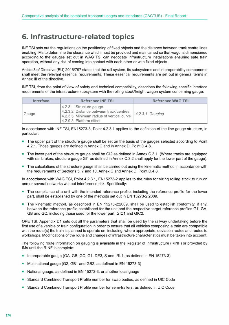
174
Comparative analysis of the combined transport usages and standards (CACTUS) - Final Report
6. Infrastructure-related topicsINF TSI sets out the regulations on the positioning of fixed objects and the distance between track centre lines enabling IMs to determine the clearance which must be provided and maintained so that wagons dimensioned according to the gauges set out in WAG TSI can negotiate infrastructure installations ensuring safe train operation, without any risk of coming into contact with each other or with fixed objects.
Article 3 of Directive (EU) 2016/797 states that the rail system, its subsystems and interoperability components shall meet the relevant essential requirements. These essential requirements are set out in general terms in Annex III of the directive.
INF TSI, from the point of view of safety and technical compatibility, describes the following specific interface requirements of the infrastructure subsystem with the rolling stock/freight wagon system concerning gauge:
Interface Reference INF TSI Reference WAG TSI
Gauge
4.2.3. . Structure gauge4.2.3.2 Distance between track centres4.2.3.5 Minimum radius of vertical curve4.2.9.3. Platform offset
4.2.3.1 Gauging
In accordance with INF TSI, EN15273-3, Point 4.2.3.1 applies to the definition of the line gauge structure, in particular:
� The upper part of the structure gauge shall be set on the basis of the gauges selected according to Point 4.2.1. Those gauges are defined in Annex C and in Annex D, Point D.4.8.
� The lower part of the structure gauge shall be GI2 as defined in Annex C.3.1. (Where tracks are equipped with rail brakes, structure gauge GI1 as defined in Annex C.3.2 shall apply for the lower part of the gauge).
� The calculations of the structure gauge shall be carried out using the kinematic method in accordance with the requirements of Sections 5, 7 and 10, Annex C and Annex D, Point D.4.8.
In accordance with WAG TSI, Point 4.2.3.1, EN15273-2 applies to the rules for sizing rolling stock to run on one or several networks without interference risk. Specifically:
� The compliance of a unit with the intended reference profile, including the reference profile for the lower part, shall be established by one of the methods set out in EN 15273-2:2009.
� The kinematic method, as described in EN 15273-2:2009, shall be used to establish conformity, if any, between the reference profile established for the unit and the respective target reference profiles G1, GA, GB and GC, including those used for the lower part, GIC1 and GIC2.
OPE TSI, Appendix D1 sets out all the parameters that shall be used by the railway undertaking before the first use of a vehicle or train configuration in order to ensure that all vehicles composing a train are compatible with the route(s) the train is planned to operate on, including, where appropriate, deviation routes and routes to workshops. Modifications of the route and changes of infrastructure characteristics must be taken into account.
The following route information on gauging is available in the Register of Infrastructure (RINF) or provided by IMs until the RINF is complete:
� Interoperable gauge (GA, GB, GC, G1, DE3, S and IRL1, as defined in EN 15273-3)
� Multinational gauge (G2, GB1 and GB2, as defined in EN 15273-3)
� National gauge, as defined in EN 15273-3, or another local gauge
� Standard Combined Transport Profile number for swap bodies, as defined in UIC Code
� Standard Combined Transport Profile number for semi-trailers, as defined in UIC Code
175
Infrastructure-related topics
� Railway location of points requiring specific checks
� Document with the transversal section of the points requiring specific checks
� Railway location of points requiring specific checks
� Document with the transversal section of the points requiring specific checks
6.1. CT linesAs the safety, performance and cost-effectiveness of combined transport are highly dependent on the optimised use of all the space provided by the railway infrastructure, a coding system has been set out in IRS 50596-6 to allow the conveyance of ILUs on suitable wagons which, as a general rule, leads to the engagement of the upper part of the gauge.
The Combined Transport Profile number (CTPn) of CT coded lines helps to establish the dimensions of ILUs that can be permitted to run along a given route when loaded on a suitable wagon marked for combined transport.
The codification of the ILU carried (TN: technical number) shall be less than or equal to the codification of the combined transport line used (CTPn) corrected by the correction number, if any, entered on the wagon.
In accordance with OPE TSI, Point 4.2.2.5.1:
� RUs are responsible for ensuring that all vehicles composing the train are compatible with the intended route(s).
� IMs shall provide the CTPn of CT lines via the RINF as part of the information required for route compatibility, as defined in Appendix D1.
6.1.1. Overview of current regulations, standards and guidelines
The following regulations, standards and guidelines were considered by the project team when performing the analysis on CT wagons.
European legal framework
� EU 321/2013: Commission Regulation concerning the technical specification for interoperability relating to the subsystem ‘rolling stock - freight wagons’ of the rail system in the European Union and repealing Decision 2006/861/EC
� EU 1299/2014: Commission Regulation on the technical specifications for interoperability relating to the ‘infrastructure’ subsystem of the rail system in the European Union
� EU 2019/773: Commission Implementing Regulation on the technical specification for interoperability relating to the operation and traffic management subsystem of the rail system within the European Union and repealing Decision 2012/757/EU
� EU 2019/776: Commission Implementing Regulation amending Commission Regulations (EU) No 321/2013, (EU) No 1299/2014, (EU) No 1301/2014, (EU) No 1302/2014, (EU) No 1303/2014 and (EU) 2016/919 and Commission Implementing Decision 2011/665/EU as regards the alignment with Directive (EU) 2016/797 of the European Parliament and of the Council and the implementation of specific objectives set out in Commission Delegated Decision (EU) 2017/1474
� EU 2019/777: Commission implementing Regulation on the common specifications for the register of railway infrastructure and repealing Implementing Decision 2014/880/EU
� EU/2020/387: Commission Implementing Regulation amending Regulations (EU) No 321/2013, (EU) No 1302/2014 and (EU) 2016/919 as regards the extension of the area of use and transition phases

176
Comparative analysis of the combined transport usages and standards (CACTUS) - Final Report
European Committee for Standardization (CEN)
� EN 15273-3: Railway applications - Gauges - Part 3: Structure gauges, Ed. 2013
International Union of Railways (UIC)
� IRS 50571-4: Wagons for combined transport - Vertical transhipment - Characteristics
� IRS 50571-5: Wagons for combined transport - Roller units for horizontal transhipment - Characteristics
� IRS 50596-6: Conditions for coding intermodal loading units in combined transport, combined transport lines and wagons, Ed. 2018
� IRS 50596-7: Railway application - Rolling stock - Conformity assessment - Requirements for bodies performing the certification of coding in accordance with UIC Leaflet 596-6 (Competent Authorities), Ed. 2017
6.1.2. Overlaps, duplications and contradictions
The goal of the comparative analysis of the documents listed in Point 6.1.1 is the identification of:
� the requirements provided by each document for selected parameters;
� overlaps, duplications and contradictions; and
� potential areas of improvement, cross-referencing and harmonisation needs (see Point 4.3).
c. Parameters and items
The analysis is focused on the following parameters:
1 Definitions
3000 General
3001 Combined Transport Profiles
3002 Combined Transport Profile number
3003 Characteristics of the reference wagons
3004 ILU technical number
600.1 Coding
700-1 Route compatibility assessment
d. Outputs of the analysis
This point gives a summary of the results of the dry and comparative analysis, and it is focused on the identification of the requirements on each parameter that are provided by the reference documents, highlighting:
� requirements that are provided by a reference document and referenced in IRS 50571-4, IRS 50571-5 and those that are not referenced;
� contradictions between the requirements provided by the different reference documents; and
� requirements that are not provided by any reference document and need to be implemented.
b.1 Summary (matrix table)
Table 5 provides a matrix compiling the parameters and the analysed reference documents.
� Requirements which are provided by each reference document with no contradictions are identified by the
following marking in a green box: NC

177
Infrastructure-related topics
� Contradictions between requirements provided by the relevant reference documents are identified by the
following marking in a red box: C
� Specific requirements provided by a reference document are identified by the following marking in a light
green box: SR
� Requirements provided by a related IRS and not considered in other reference documents are identified by the following marking in an orange box: Not in IRS 5057X-Y
� Requirements provided by a related IRS and not referenced in other reference documents are identified by
the following marking in a yellow box: A → EU 20XX/YY
� Requirements that are not considered in the relevant reference documents are identified by the following
marking in a grey box: NR
� Requirements which are out of the scope of the related documents are identified by the following marking
in a light brown box: NA

178
Comparative analysis of the combined transport usages and standards (CACTUS) - Final Report
Tabl
e 5:
CT
lines
: sum
mar
y m
atrix
Para
met
erD
irect
ive
(EU
) 201
6/79
7 (In
tero
pera
bilit
y)
Dire
ctiv
e (E
U)
2019
/778
(RIN
F)IN
F TS
IW
AG
TSI
OPE
TSI
IRS
5057
1-4
IRS
5057
1-5
IRS
5059
6-6
IRS
5059
6-7
1SR
SRSR
SRSR
SRSR
SRSR
3000
NR
NA
SRSR
(1)
NR
NC
NC
A →
INF
TSI
NA
3001
NA
NC
CC
CN
CN
CA
→ IN
F TS
IN
A30
02N
AN
CC
CC
NC
NC
A →
INF
TSI
NA
3003
NA
NA
CC
CN
CN
CA
→ IN
F TS
IN
A30
04N
AN
AC
CC
NA
NA
SRN
A60
0.1
NC
NC
CN
AN
RN
CN
CSR
NC
700-
1N
CN
CN
CN
CN
CN
AN
AN
RN
A
(1) S
ee a
lso
Poin
t 4.2
(Wag
ons)
, Tab
le 1
and
Par
amet
ers
1401
to 1
411.

179
Infrastructure-related topics
b.2 Summary of the outputs of the performed analysis
The following describes in detail - for each parameter - the requirements provided by the reference documentation underlining the contradictions, overlaps and possible gaps. For ease of reading, a comprehensive description of each parameter has been added.
� Definitions (Parameter 1)
Definitions of the infrastructure parameters and topics relating to CT line coding are provided in all the reference documents.
The search for appropriate definitions is difficult, and overlaps and differences exist.
� General (Parameter 3000)
Where the definition of the space to be cleared and maintained to allow the conveyance of ILUs on CT wagons running without risk of interference on CT lines that are part of one or several networks is concerned, the following TSIs apply:
y Technical specifications for interoperability relating to the operation and traffic management subsystem of the rail system (OPE TSI)
y Technical specifications for interoperability relating to the infrastructure subsystem (INF TSI)
y Technical specifications for interoperability relating to the subsystem ‘rolling stock - freight wagons’ (WAG TSI)
As defined in IRS 50596-6 and in addition to the requirements provided by WAG TSI, CT wagons shall be compliant with the requirements provided in IRS 50571-4, IRS 50571-5 and IRS 50596-6, Point 3 and Appendices A.1 to 4 to allow them to be marked with the relevant wagon compatibility code (WCC).
� Combined Transport Profiles (Parameter 3001)
A CTP represents a completely closed envelope, with specified shape and dimensions, within which a given ILU, in the loaded position on a wagon, shall be inscribed.
In accordance with IRS 50596-6, any CTP consists of a ‘lower part’ and an ‘upper part’.
y The ‘lower part’ is defined by a lower outline specific to each type of wagon and by the technical conditions applicable to each ILU.
y The ‘upper part’ depends on the ILU (semi-trailer, swap body, roller unit, etc.) and is specified in Appendices B to E.
The provision of requirements on Combined Transport Profiles is out of the scope of Directive (EU) 2016/797 and IRS 50596-7.
Directive (EU) 2019/778 refers to CTP as per UIC code.
INF TSI, WAG TSI and OPE TSI do not consider combined transport. Two CTP types are considered in IRS 50596-6:
y Standard profiles which apply to all types of semi-trailers, swap bodies, ISO containers and roller units.
y Special profiles which apply to flat roof semi-trailers, swap bodies and roller units.
NB For gauge reasons, lines in Great Britain are only coded according to special profiles.
IRS 50596-6 provides families of CTPs which shall be applied when lines are coded. Families of profiles have been identified depending on the typology of the ILU:
y Appendix B.1: Semi-trailers with a maximum width of 2,500 mm
y Appendix B.2: Semi-trailers with a width greater than 2,500 mm and less than or equal to 2,600 mm

180
Comparative analysis of the combined transport usages and standards (CACTUS) - Final Report
y Appendix C.1: Swap bodies and roller units with a maximum width of 2,550 mm
y Appendix C.2: Swap bodies and roller units with a width greater than 2,550 mm and less than or equal to 2,600 mm
y Appendix D.1: Flat roof semi-trailers with a maximum width of 2,500 mm (special profile)
y Appendix D.2: Flat roof semi-trailers with a width greater than 2,500 mm and less than or equal to 2,600 mm (special profile)
y Appendix D.3: Flat roof swap bodies and roller units with a maximum width of 2,550 mm (special profile)
y Appendix D.4: Flat swap bodies and roller units with a width greater than 2,550 mm and less than or equal to 2,600 mm (special profile)
y Appendix E: ISO containers (width = 2,438 mm)
There are no contradiction between IRS 50596-6, IRS 50571-4 and IRS 50571-5.
� Combined Transport Profile number (Parameter 3002)
In accordance with IRS 50596-6, the CTP number consists of:
2 digits for:
3 digits for:
y semi-trailers up to a maximum width of 2,500 mm;
y swap bodies and roller units up to a maximum width of 2,550 mm; and
y ISO containers up to a maximum width of 2,438 mm.
y semi-trailers wider than 2,500 mm but not wider than 2,600 mm; and
y swap bodies and roller units wider than 2,550 mm but not wider than 2,600 mm.Appendices B to E set out 100 profiles numbered from 00 to 99 and 330 to 429 in 10 mm height increments.
The provision of requirements on this parameter is out of the scope of Directive (EU) 2016/797 and IRS 50596-7.
Directive (EU) 2019/778 integrates the CTPn as per UIC code in the list of items related to the line layout to be registered by IMs in the RINF.
INF TSI, WAG TSI and OPE TSI do not consider combined transport.
There are no contradictions between IRS 50596-6, IRS 50571-4 and IRS 50571-5.
� Characteristics of the reference wagon (Parameter 3003)
“P” Combined Transport Profiles are calculated on the basis of the characteristics of the reference recess wagon (referred to hereafter as ‘reference wagon’) provided in IRS 50596-6, Point 1.4:
y Distance between bogie pivots (a) 11,200 mm
y Bogie wheelbase (p) 1,800 mm
y Height of ST loading plane 330 mm
y Maximum overhang (na) 2,000 mm
y Load tolerance 10 mm
y Dissymmetry 1°
y Height of ST + wagon roll centre (Hc) 1,000 mm
y (q + w) play 11.5 mm
y Play inside bearers (J) 12 mm

181
Infrastructure-related topics
y Half-distance between side bearers (bG) 850 mm
y ST + wagon flexibility (s) 0.3
“C” and “ISO” Combined Transport Profiles are calculated on the basis of the characteristics of the reference wagon (referred to hereafter as ‘reference wagon’) provided in IRS 50596-6, Point 1.4:
y Distance between bogie pivots (a) 13,500 mm
y Bogie wheelbase (p) 1,800 mm
y Height of swap body loading plane 1,175 mm
y Maximum overhang (na) 2,000
y Load tolerance 10 mm
y Dissymmetry 1°
y Height of wagon roll centre (Hc) 500 mm
y (q + w) play 11.5 mm
y Play inside bearers (J) 12 mm
y Half-distance between side bearers (bG) 850 mm
y Wagon flexibility (s) 0.15
The provision of requirements on the characteristics of the reference wagon is out of the scope of Directive (EU) 2016/797, Directive (EU) 2019/778 and IRS 50596-7.
INF TSI, WAG TSI and OPE TSI do not consider combined transport.
There are no contradictions between IRS 50596-6, IRS 50571-4 and IRS 50571-5.
� ILU technical number (Parameter 3004)
In accordance with IRS 50596-6, the coding plate provides the ILU technical number which consists of:
y the WCC of the compatible wagon (P, N, C, ISO or B) and the code of the special profile (flat roof ILUs);
y the standard Combined Transport Profile number (2 or 3 digits); and
y for flat roof ILUs, the special Combined Transport Profile number (2 or 3 digits).
ISO containers are not coded, but they are considered as follows:
y ISO container, height: 8 ft ≈ C 00 → ISO 00
y ISO container, height: 8 ft 6 in ≈ C 12 → ISO 14
y ISO container, height: 9 ft 6 in ≈ C 44 → ISO 45
The provision of requirements on this parameter is out of the scope of Directive (EU) 2016/797, Directive (EU) 2019/778, IRS 50571-4, IRS 50571-5 and IRS 50596-7.
INF TSI, WAG TSI and OPE TSI do not consider combined transport.
� Coding (Parameter 600.1)
In accordance with IRS 50596-6, CT lines shall be coded, taking into account:
y ILU types (semi-trailers → P / swap bodies and roller units → C / special profiles → S);
y Combined Transport Profiles; and

182
Comparative analysis of the combined transport usages and standards (CACTUS) - Final Report
y the parameters of the reference wagons.
IRS 50596-6 provides:
y CTPs for coding lines and ILUs relating to:
• semi-trailers:
• Max. width = 2,500 mm (Appendix B.1)
• 2,500 mm ≤ max. width ≤ 2,600 mm (Appendix B.2)
• flat roof semi-trailers:
• Max. width = 2,500 mm (Appendix D.1)
• 2,500 mm ≤ max. width ≤ 2,600 mm (Appendix D.2);
• swap bodies and roller units:
• Max. width = 2,500 mm (Appendix C.1)
• 2,500 mm ≤ max. width ≤ 2,600 mm (Appendix C.2)
• flat roof swap bodies and roller units:
• Max. width = 2,500 mm (Appendix D.3)
• 2,500 mm ≤ max. width ≤ 2,600 mm (Appendix D.4)
• ISO containers (Appendix E);
y the characteristics of the reference wagon for coding CT lines and ILUs (Point 1.4, Point 1.5 and Appendix A); and
y the criteria determining the Combined Transport Profile number for a given route by the infrastructure manager in accordance with its methodology (Point 4.3).
IRS 50596-7, Point 3 allocates the responsibility for CT line coding to IMs as per IRS 50596-6.
There are no contradictions with:
y Directive (EU) 2016/797, which clarifies the roles of RUs and IMs in relation to the checks to be performed before the use of authorised vehicles and confers on IMs the responsibility for collecting the data relating to their network and ensuring that registered data is complete, consistent, accurate and up to date.
y Directive (EU) 2019/778 on common specifications for the register of railway infrastructure (RINF), which includes in the list of the network characteristics the Standard Combined Transport Profile numbers for swap bodies and semi-trailers defined as “Coding for combined transport with swap bodies and semi-trailers as defined in UIC Code”.
INF TSI does not indicate the Combined Transport Profile number as a parameter (neither basic nor performance) for defining the European Union railway target system.
In that respect, for freight traffic, INF TSI defines ‘gauge’ as a performance parameter and IMs, when assigning an INF TSI traffic code to their lines, shall choose between the following gauges (defined in EN 15273-3):
y GC
y G
y GA
y G1
183
Infrastructure-related topics
y S
y IRL1
No reference to CT line coding or specific requirement is provided in OPE TSI. The provision of requirements on this parameter is out of the scope of WAG TSI.
� Route compatibility assessment (Parameter 700-1)
There are no contradictions between Directive (EU) 2016/797, Directive (EU) 2019/778, OPE TSI, INF TSI, WAG TSI and IRS 50596-6:
y In accordance with Directive (EU) 2016/797 (Article 23), before an RU uses a vehicle in the area of use specified in its authorisation for placing on the market, it shall check that the vehicle is compatible with the route on the basis of the infrastructure register, the relevant TSIs or any relevant information to be provided by the infrastructure manager free of charge and within a reasonable period of time, where such a register does not exist or is incomplete.
y In accordance with OPE TSI, Point 4.2.2.5.1:
• RUs are responsible for ensuring that all vehicles composing the train are compatible with the intended route(s).
• IMs shall provide the information for route compatibility as defined in Appendix D1 via the RINF.
The route compatibility process shall not duplicate processes performed as part of the vehicle authorisation to ensure technical compatibility between the vehicle and the network(s).
Parameters of Appendix D1 already verified and checked during vehicle authorisation or other similar processes shall not be reassessed as part of the route compatibility check.
For vehicles authorised under Directive (EU) 2016/797, the relevant vehicle data related to the parameters listed in Appendix D1, already checked during the authorisation process, are part of the technical file of the wagon and shall be provided by the applicant for the vehicle authorisation or the keeper to the railway undertaking upon request, when such information is not available in ERATV or other registers for rail vehicles.
For vehicles authorised before Directive (EU) 2016/797, the relevant vehicle data related to the parameters listed in Appendix D1 shall be provided to the railway undertaking by the holder of the vehicle authorisation documentation or the keeper upon request, when such information is not available in ERATV or other registers for rail vehicles.
No additional requirements are provided in IRS 50596-6.
The provision of requirements on this parameter is out of the scope of IRS 50571-4, IRS 50571-5 and IRS 50596-7.
6.1.3. Potential areas of improvement, cross-referencing and harmonisation needs
Based on the results of the dry and comparative analysis (see Point 4.2), the following areas were identified as requiring improvement and harmonisation.
The UIC and UIRR recommendations for better harmonisation and integration of the requirements for coding CT lines and the assessment of the compatibility between CT wagons carrying coded ILUs and routes are the subject of Chapter 7 of this report.
A. Vocabulary
As highlighted in the summary of the results of the analysis performed on ILUs and CT wagons, some definitions and descriptions relating to CT line coding, although not in conflict with each other, have been provided in all the reference documents considering the prevailing scope of the directives, regulations, standards and guidelines.

184
Comparative analysis of the combined transport usages and standards (CACTUS) - Final Report
There is currently no EN standard or UIC document available that provides definitions of terms relating to CT line coding which could be used as a reference for all EN standards and other technical documents on combined road-rail transport.
B. CT lines codification methodology
INF TSI does not indicate the Combined Transport Profile as a parameter (neither basic nor performance) for defining the target system of EU railway infrastructure.
The methodology used by IMs to define the Combined Transport Profile of a line may differ from the harmonised methodology used for the definition of the clearance gauge of the line and varies from country to country, as it depends on the national regulations in force on the subject.
CT lines are coded in accordance with the CTPs provided in IRS 50596-6, but the methodologies applied by IMs are not uniform, as they depend on national regulations.
The Combined Transport Profile number (CTPn) assigned to a line identifies the highest CTP permitted which is compatible with:
� A standard structure gauge corresponding to the related parameter of the line as per INF TSI, Point 4.2.1 and Table 3 (GA, GB, GC, G1, S and IRL1);
� A specific structure gauge defined in EN 15273-3 or a national structure gauge which has been defined to increase the performance of CT trains running on the line; or
� the real position of the obstacles (in this case, the national regulations on exceptional consignments apply).
The inclusion of the CTPn as per IRS 50596-6 in the list of the performance parameters for freight traffic in INF TSI (Point 4.2.1, Table 3) is the first step to ensure the transparency of the relevant information on CT lines provided by IMs to RUs.
A second step will be the definition of a harmonised methodology for determining the CTPn to be assigned to CT lines by IMs.
B.1 The UIC “G CODE - Clearance gauge common codification” Project
In 2020, UIC launched the project “G CODE - Clearance gauge common codification” to facilitate the process for verifying the compatibility of CT wagons carrying ILUs with infrastructure in order to improve network accessibility and the interoperability of CT trains on coded lines.
The UIC project aims to define a harmonised methodology for coding CT lines in accordance with IRS 50596-6 requirements, improving interoperability and network accessibility throughout the EU network, by accelerating and simplifying the process and enabling the maximum capacity of railway lines, optimised routing, and available alternative routes.
The project consists of the following four work packages:
WP1: Benchmark
State of the art on infrastructure and rolling stock codification considering:
� Current national regulations and practices;
� IRS 50571-4, IRS 50571-5, IRS 50591, IRS 50592, IRS 50596-5 and IRS 50596-6;
� UIC Leaflets 502-x and 505-y;
� EN 15273-1 to 3, EN-13044-a and 15877-1; and
� OSJD standards on the loading gauge, which are progressively being considered in the revision of UIC leaflets into IRS.

185
Infrastructure-related topics
WP2: Infrastructure and rolling stock assessment
� Analysis of parameters, factors and established rules affecting railway clearance gauge.
� Revision and description of responsibilities (for IMs and RUs) for determination, computation, assessment of compatibilities, monitoring and maintenance of railway clearance gauge.
WP3: Development of an application software tool
� Development of a software tool which:
y allows the verification of the compatibility and correspondence between the different CT wagons loaded with ILUs and infrastructure type gauges; and
y ensures maximum capacity of railway lines, allowing proposals for optimised routing, and proposing available alternative routes, based on RTM and other similar open application tools for railway network representation.
WP4: Guidelines
� Definition of guidelines: “Railway gauge - common rules for infrastructure and rolling stock for a harmonised CT coding methodology”; and
� Proposal for IRS: “Harmonised CT coding methodology on railway gauge”.
The key outcomes of the project, will be:
� guidelines on the application of the methodology for CT lines; and
� a software tool that allows the verification of compatibility and correspondence between line gauges and Combined Transport Profiles.
The new harmonised methodology will enhance the rail sector and make it more competitive compared to other modes of transport, helping to improve interoperability by significantly reducing costs and administrative procedures for IMs, and for RUs wishing to operate across Europe.
This initiative will consider the new requirements and challenges put forward by freight operators and wagon keepers in combined transport, where the cohesiveness of the coding system in accordance with IRS 50596-6 requirements is a key element for the transport and logistics processes involving CT lines, ILUs and CT wagons.
The project could take advantage of new digital capabilities, helping to identify bottlenecks and ensuring maximum capacity of railway lines, allowing proposals for optimised routing, and proposing available alternative routes, based on RTM and other similar open application tools for railway network representation.
For this purpose, it is important to consider both infrastructure (IMs participating in the UIC Rail System Forum) and freight perspectives (RU members of the UIC Freight Forum). The project team will also have to establish communication with representatives of related key actors, such as ERA (European Union Agency for Railways), UIRR (International Union for Road-Rail combined transport) and several RFC (Rail Freight Corridor) operators.
C. Transparency of the information provided by IMs to RUs on CTPs accepted on CT routes
In accordance with Directive (EU) 2016/797, it is up to RUs to carry out the route compatibility check. For this purpose, RUs need the relevant information in the RINF.
Availability and reliability of information on CTPs will speed up compatibility check processes and facilitate combined transport.
Together with the inclusion of the CTPn as a basic or performance parameter in INF TSI and the definition of a harmonised methodology for the allocation of CTPn to CT lines, the availability in the RINF of the full information on CTPs assigned to the EU railway network will increase the transparency of the CT route compatibility assessment process.
186
Comparative analysis of the combined transport usages and standards (CACTUS) - Final Report
D. Information for CT users on CTPs accepted on CT lines
At present there is no EU official map of railway lines coded for swap bodies and semi-trailers available. A snapshot of the situation of European lines is shown by the commercial maps published by the UIRR (version 2019) which provides the CTP numbers assigned to the lines (swap bodies/semi-trailers).
The publication of an EU official map, providing for each line the CTP numbers registered in the RINF, will make combined transport information more user friendly, help shippers to find more suitable routes for delivering ILUs, increase trust among stakeholders and widen the business market.

187
Recommendations
7. RecommendationsBased on the results of the performed analysis, the joint UIC/UIRR Project Group has drawn up recommendations as a contribution to the facilitation of combined transport in Europe.
The recommendations concern the harmonisation and integration of the requirements on the interoperability and operation of CT wagons, ILUs, CT lines and codification into the EU legal framework, ISO and EN standards, IRSs, UIC Loading Guidelines and the GCU.
7.1. The codification system
7.1.1. Integration of the UIC codification system into TSIs
The codification system as per IRS 50596-6 was established by UIC in collaboration with UIRR to facilitate and speed up the conveyance of ILUs in combined transport.
The provisions governing the UIC codification system are not integrated or referenced in the European legal framework (EU directives and TSIs) and are out of the scope of EN standards relevant to wagons and ILUs.
R.1. A specific TSI on Combined Transport shall be created.
This new TSI will cover those aspects of the infrastructure, operation and traffic management, and rolling stock subsystems which are relevant to the interoperability of ILUs loaded on suitable wagons and conveyed:
1. on conventional lines for freight and mixed traffic (passenger and freight); and
2. through freight hubs, including intermodal terminals.
The new TSI to be applied to:• lines, intermodal terminals and hubs on which the CT trains are operated;• CT wagons which are in the scope of WAG TSI (integrated with the requirements provided in IRS
50571-4, IRS 50571-5 and IRS 50596-6); and• ILUs compliant with the relevant EN and ISO standards, IRS 50591, IRS 50592 and IRS 50596-5
and codified in accordance with IRS 50596-6.
The integration of the codification system as per IRS 50596-6 into INF TSI and OPE TSI and the updating of WAG TSI (see recommendations R.4, R.5, R.6, R.10 and R.17) and INF TSI (see recommendation R.28) will minimise the technical, operational and administrative barriers to combined rail-road transport in Europe.
Although the Combined Transport Profile number allocated to CT lines is part of the information which shall be provided by IMs in the RINF, no requirement on it is provided in INF TSI.
R.2. The Combined Transport Profile number (CTPn) of lines as per IRS 50596-6 to be introduced into:• the list of performance parameters for freight traffic provided in INF TSI (Point 4.2.1, Table 3);• the list of the interface requirements of the infrastructure subsystem with rolling stock/freight
wagons (Point 4.3.1, Table 15); and• the list provided in OPE TSI, Appendix D1 relating to the parameters that shall be used in the
process carried out by railway undertakings before the first use of a vehicle or train configuration to ensure that all vehicles composing a train are compatible with the route(s) the train is planned to operate on (including, where appropriate, deviation routes and routes to workshops).
When integrated into INF TSI and OPE TSI, the codification of CT routes will become a mandatory issue and it will improve the interoperability and accessibility of the network throughout the EU.
188
Comparative analysis of the combined transport usages and standards (CACTUS) - Final Report
7.1.2. Entities responsible for the codification of CT lines and ILUs and the allocation of correction digits to CT wagons
IRS 50596-7 defines the roles and requirements of the entities in charge of coding CT lines, approving and coding ILUs, and allocating correction digits to CT wagons.
IRS 50596-7 assigns the responsibility for:
� coding CT lines to the IMs involved for each line;
� approving and coding ILUs to:
y National Safety Authorities,
y infrastructure managers,
y freight railway undertakings, and
y subjects delegated by the above-mentioned entities; and
� allocating correction digits to National Safety Authorities or infrastructure managers.
The lists of the bodies which are recognised by UIC to grant codification, to approve ILUs, to deliver coding plates and to allocate correction digits are provided by IRS 50596-6, Appendix H.1.
The role, competencies and responsibilities of the entities in charge of the codification of ILUs and the allocation of correction digits to CT wagons are not defined at EU level.
R.3. The role, competencies and responsibilities of the entities in charge of the approval and codification of ILUs and the allocation of correction digits to CT wagons to be integrated into a specific TSI on Combined Transport.
The relevant parts of IRS 50596-7 to be referenced in the new TSI on Combined Transport.
The regulation of the roles, competencies and responsibilities at EU level will spread and make the processes for the approval and codification of ILUs and the allocation of correction digits to CT wagons more efficient and consistent.
7.1.3. Guide to the application of relevant CT documents
The CACTUS analysis demonstrates that the reference documentation on combined transport (wagons, ILUs, lines, coding, operation, etc.) is extensive and highly detailed. An Application Guide is therefore necessary to provide information on how to apply the related legal framework, ISO standards, EN standards and UIC technical documents (IRSs and Loading Guidelines) to combined transport .
R.4. ERA to publish a guide for the application of the TSI on Combined Transport, providing users with a complete overview of the reference document content and explaining how to fulfil their requirements.
The guide will consist of a general part, providing explanations of key concepts, roles and the framework, and specific parts focusing on:• ILU approval,• ILU certification,• ILU codification,• allocation of the wagon compatibility code and correction digits to CT wagons, and• codification of CT lines.

189
Recommendations
The Application Guide will facilitate CT stakeholder understanding and application of current relevant reference documents, by explaining how CT wagons, CT lines and ILUs must be built, assessed and coded in order to comply with the essential requirements provided by the above-mentioned documentation.
7.2. CT wagons
7.2.1. Requirements specific to CT wagon
Like all types of freight vehicles, CT wagons are covered by the provisions of WAG TSI and NOI TSI. However, the requirements specific to CT wagons which are provided in IRS 50571-4, IRS 50571-5 and IRS 50596-6 are not integrated into WAG TSI.
R.5. The following specific requirements on CT wagons to be integrated in WAG TSI:• Shape and dimensions of the spigots.• Strength and materials of the spigots, their components and their attachments to the underframe
of the wagons which are suitable for the conveyance of standard ILUs and/or heavy-duty ILUs (MGM > 36,000 kg).
• Limit dimensions and positions of the spigots which are permitted in manufacturing and operation.• Functions, technical characteristics and strength of the seating device (under various conditions).• Functions and characteristics of the locking device that in any case shall be designed to allow
any inspection staff (terminal operators, RUs, etc.) to check that the semi- trailer king pin has been correctly locked in the seating device.
• Functions, technical characteristics and strength of the pivoting frames.• Functions and characteristics of the device for locking the pivoting frames to the wagon
underframe, and the roller unit to the pivoting frame, that shall be designed to allow RU staff to check that the pivoting frame and roller unit are correctly secured.
7.2.2. The allocation of the WCC and correction digits
The criteria provided in IRS 50596-6 for the allocation of the WCC marking to CT wagons compliant with the requirements provided in IRS 50596-6 and of the positive correction digit to CT wagons whose characteristics are more favourable than those provided in IRS 50596-6 are not integrated into WAG TSI and they are not considered during the conformity assessment of the CT wagon type made by the Notified Body as part of the authorisation process as per Directive (EU) 2016/797, Article 24.
The allocation of the negative correction digit is part of the process performed by RUs to assess the compatibility of a CT wagon type loaded with the related ILUs before its authorisation for placing on the market. The correction digit is defined by IMs according to national regulations.
As evidenced by the list published in IRS 50596-6, Appendix H1, the bodies which are responsible for the allocation of the WCC and correction digits do not cover all EU Member States. A harmonised method for the definition of the negative correction digit does not exist.
R.6. The following requirements provided in IRS 50596-6 with an impact on the allocation of the WCC and correction digits should be integrated into WAG TSI:• Height of the loading plane• Bogie wagons: distance between the pivots• 2-axle wagons: wagon wheelbase• Overhang• Bogie wheelbase• Side bearers• Side bearers play (j)
190
Comparative analysis of the combined transport usages and standards (CACTUS) - Final Report
• Half-distance between side bearers (bG)• Total lateral play (q+w)• Vehicle flexibility coefficient (s)• Dissymmetry (η0)• Height of the roll centre• Tolerances (centring)• Tolerances to the right of the tyres• Tolerances to the right of the king pin• Tolerances to the right of the spigots
R.7. A harmonised methodology for the allocation of the negative correction digit to CT wagons based on the kinematic calculation of the lineside clearances and on the determination of the related margins in accordance with uniform criteria based on the results (IRS and guidelines) of the ongoing UIC project “G CODE - clearance gauge common codification” to be referenced in INF TSI and WAG TSI.
As a result of the introduction of the parameters provided in IRS 50596-6 into WAG TSI, the allocation of the WCC marking and the definition of the positive correction digit which depend only on the characteristics of the wagon will become part of the assessment performed by the Notified Body in the process for the authorisation of the wagon.
The definition of a harmonised methodology for the calculation of the negative correction digit to be referenced in WAG TSI and INF TSI will minimise the differences between the values of the negative correction digits authorised by IMs in the different EU Member States.
7.2.3. Articulated CT wagons payload
In accordance with EN 15528, the calculated payload limits are only valid if the permissible payload is evenly distributed over the length of the wagon. In the case of longitudinally displaced or unevenly distributed loading, the payload shall be reduced, so that the value of the permissible axle load is not exceeded.
R.8. A methodology for the calculation of the payload of articulated CT wagons to be integrated into EN 15528 taking into account the mass, the length of the loaded ILUs and their position and possible combinations.
The number of articulated wagons represents a significant proportion of the CT wagon fleet. Due to the maximum gross mass, ILU length and their combinations when they are loaded on the wagons, the distribution of the wagon load is never uniform. The reduction of the payload will, in most cases, put articulated wagons out of market.
7.2.4. Wagons suitable for the conveyance of non-craneable semi-trailers
Requirements for wagons suitable for the conveyance of semi-trailers which are not fitted with vertical lifting devices (hereafter called ‘non-craneable’ semi-trailers) are not provided in IRS 50571-4.
R.9. Requirements for• wagons suitable for the conveyance of non-craneable semi-trailers which can only be handled
horizontally and• the interfaces enabling the vertical handling and loading of non-craneable semi-trailers on pocket
wagons
to be introduced into IRS 50571-4.

191
Recommendations
R.10. Conditions for the codification of non-craneable semi-trailers when they are loaded• horizontally on suitable wagons and• vertically on pocket wagons using interfaces
to be introduced into IRS 50596-6.
R.11. New requirements in IRS 50571-4 and IRS 50596-6 relating to CT wagons suitable for the conveyance of non-craneable semi-trailers to be integrated into WAG TSI.
7.2.5. Maintenance
No provision governing the maintenance of the components fitted to CT wagons to secure ILUs (seating devices, spigots, pivoting frames, etc.) is provided in the GCU, Appendix 10.
R.12. Conditions for the maintenance of• seating devices of pocket wagons (including their locking system),• spigots of CT wagons and• pivoting frames fitting CT wagons suitable for the conveyance of roller units (including their
securing and locking system)
to be introduced into the GCU, Appendix 10.
7.3. Intermodal Loading Units
7.3.1. Vocabulary
In all the reference documents, the terminology and definitions used, although not in conflict with each other, are different because of the prevailing scope of the directives, regulations, standards and guidelines.
No EN standard or UIC document providing a vocabulary of terms and definitions related to ILUs exists.
R.13. An EN standard on the terms and definitions related to ILUs to be created.
The EN standard on ILU vocabulary will be the reference for all EN standards relating to combined transport, legal documents (directives, regulations, TSIs, recommendations, etc.) and other technical documents on rail-road combined transport.
7.3.2. Markings
The number of markings to be placed on ILUs suitable for rail transport is significant and often spread across different EN standards, IRSs and the UIC Loading Guidelines.
R.14. An EN standard providing• the characteristics of the markings,• the requirements pertaining to their presentation,• their shape and position on the semi-trailer and• their meanings
to be created.

192
Comparative analysis of the combined transport usages and standards (CACTUS) - Final Report
The reference to a single technical document will avoid mistakes and inconsistencies when the markings are applied to ILUs and facilitate the activity of RU inspection staff.
7.3.3. Harmonisation of current regulations, standards and guidelines on cargo securing for different modes of transport
Several regulations, standards and loading guidelines lay down provisions for securing cargo in loading units. In some cases, the provisions apply to a single transport mode (rail, road or sea); in other cases, they apply to more than one transport mode (rail and road); and they may be applied to combined transport.
As the criteria for the definition of such provisions often differ, the basic requirements in each regulation and standard are different for each mode of transport, i.e.
� the values and the combination of the accelerations for the design of cargo securing arrangements in different directions,
� the basic design principles for top-over lashing and blocking such as friction, safety factors, permissible free space, etc.
� the use of safety factors,
� the permissible free space in a blocking arrangement within a cargo transport unit.
R.15. A set of harmonised load securing best practice guidelines, information, and training materials for railway undertakings, cargo owners, logistic services, providers and forwarders to be defined at European level.
The above-mentioned guidelines will be the reference for a common learning action to improve efficiency in the intermodal transport chain and to deploy best practices in the implementation of existing standards related to load securing.
7.3.4. Updating of EN standards, IRSs and other relevant technical documents
During the last five years, new and updated EN standards and IRSs have been published, and the GCU and UIC Loading Guidelines are updated annually. New and updated requirements are going to be updated or introduced.
R.16. ILU-related technical documents (EN standards, IRSs, UIC Loading Guidelines, etc.) to be revised:• to introduce the new and updated requirements and cross-references between standards; and• to eliminate the overlaps, contradictions and deficiencies highlighted by the analysis carried out
as part of the CACTUS Project.
EN standards:• EN 283• EN 284• EN 452• EN 1432• EN 12406• EN 12410• EN 13044-1• EN 13044-2• EN 13044-3• EN 16973
IRS:• IRS 50592• IRS 50596-5• IRS 50596-6• IRS 50596-7
UIC Loading Guidelines, Volume 2.

193
Recommendations
The new editions of the technical documents will be focused on:
� the requirements on standardisation of ILUs and their components (ISO and EN standards);
� the requirements based on the needs of railway operators and related to the interoperability and safety of rail transport (IRSs);
� the provision of railway operators with precise indications on loading standards, safety inspections at the time of acceptance of transport, and identification of ILUs (the GCU and UIC Loading Guidelines).
7.3.5. FEM calculations
In some cases, EN standard and IRS requirements on tests to be performed on ILUs to prove their ability to withstand the stresses occurring during transport and handling enable the replacement of tests by FEM calculations.
R.17. A uniform protocol for the validation of CAD/FEM calculations to be referenced in ILU-related EN standards.
R.18. Obligation of wagon manufacturers to provide information on the calculations made to define the wagon structure upon the request of ILU manufacturers, and requirements on the documentation to be provided to be introduced into WAG TSI.
The reference in ILU-related standards and IRSs to a protocol for the validation of CAD/FEM calculations and the introduction into WAG TSI of the obligation of the wagon manufacturers to provide information on the calculations made to define the wagon structure upon the request of ILU manufacturers will make the replacement of some tests with FEM calculation feasible.
7.3.6. Semi-trailers
7.3.6.1. Semi-trailers are not considered to be ILUs in the EU legal framework
Although semi-trailers are considered by Council Directive 92/106/EEC as combined transport units as well as lorries, trailers, swap bodies or containers of 20 ft or more, Directive 96/53/EC and Directive (EU) 2015/719 do not identify semi-trailers as ILUs.
R.19. Directive (EU) 96/53/EC (amended by Directive (EU) 2015/719) to be modified to consider semi-trailers suitable for conveyance by rail as Intermodal Loading Units.
The recommended amendment will eliminate a gap in the appliable EU legal framework.
7.3.6.2. Types of semi-trailers which are not considered in the reference documentation
The following types of semi-trailers are not considered in any EN standard or IRS:
� Semi-trailers not fitted with vertical lifting devices (hereafter called ‘non-craneable’ semi-trailers) which may be:
y handled
• horizontally or
• vertically using interfaces that enable them to be lifted by cranes and reach stackers; and
y conveyed on
• specialised wagons or
• fixed pocket wagons
194
Comparative analysis of the combined transport usages and standards (CACTUS) - Final Report
� Thermal semi-trailers
� Tank semi-trailers
� Semi-trailers fitted with aerodynamic devices
R.20. Semi-trailers not fitted with vertical lifting devices (non-craneable semi-trailers)
a. The main dimensional and design characteristics, ratings and test methods of semi- trailers which are not fitted with vertical lifting devices to be defined in EN 16973.
b. A new chapter of IRS 50596-5 laying down the following provisions to be defined:• Requirements on the compatibility of non-craneable semi-trailers with wagons intended for
their conveyance.• Strength requirements of the structure and components of non-craneable semi- trailers.• Parameters and their related values to be considered for the codification of non- craneable
semi-trailers and CT lines for the transport of semi-trailers on wagons other than pocket wagons.
• Any operational measures necessary for the conveyance, handling and inspection of non-craneable semi-trailers.
• Specific markings.
c. The characteristics of specialised wagons suitable for the conveyance of semi-trailers not fitted with vertical lifting devices and the characteristics of the interfaces enabling non- craneable semi- trailers to be lifted by cranes and loaded onto fixed pocket wagons to be integrated into IRS 50571-4.
R.21. Thermal semi-trailers
The main dimensional and design characteristics, ratings and test methods of thermal semi- trailers to be defined in EN 16973.
Specific operational requirements to be integrated into IRS 50596-5.
Conformity with the ATP to be introduced in EN 16973 and IRS 50596-5.
R.22. Tank semi-trailers
The main dimensional and design characteristics, ratings and test methods of tank semi- trailers (including those designed for the carriage of goods defined as dangerous by RID) to be defined in EN 16973.
Specific operational requirements to be integrated into IRS 50596-5.
R.23. Semi-trailers fitted with aerodynamic devices
The main dimensional and design characteristics, ratings and test methods of semi-trailers fitted with aerodynamic devices to be defined in EN 16973.
The impact of the dimensions of the semi-trailer to be considered in the determination of the semi-trailer envelope provided in IRS 50596-5.
Specific operational requirements to be integrated into IRS 50596-5.
Specific markings for semi-trailers fitted with aerodynamic devices to be integrated into IRS 50596-5 and UIC Loading Guidelines, Volume 2.

195
Recommendations
7.3.6.3. Maintenance
The maintenance of rail vehicles is governed by Directive 2014/45/EU. For the time being, there is no European obligation to affix the date of the next inspection on semi-trailers.
R.24. Requirements on semi-trailer maintenance to be integrated by:
a. introducing the obligation to affix the date of the next roadworthiness test on semi- trailers into the European legal framework (Directive 2014/45/EU) and designing an adequate marking;
b. updating the current Annex 1 of Directive 2014/45/EU with additional items to be controlled (e.g. tarpaulins, king pin, body structure, craneability features, etc.);
c. adding, as a cross-reference, the new marking in EN 16973;
d. introducing in the catalogue of irregularities provided in the GCU, Appendix 9, Annex 1:• the expiration of the date of the next roadworthiness test and the lack of the related marking;
e. making reference in IRS 50596-5 to the new marking provided by EN 16973; and
f. introducing the marking in UIC Loading Guidelines, Volume 2, Point 9.4.
The recommended measures shall improve the safety levels of road and railway operations avoiding the risk of handling and carrying semi-trailers which have not been submitted to the periodic roadworthiness test in due time.
7.3.7. Swap bodies
7.3.7.1. Swap bodies suitable for the carriage of concentrated loads and flat swap bodies
Requirements on swap bodies suitable for the conveyance of concentrated loads and flat swap bodies are not provided by any EN standard on swap bodies.
R.25. Requirements on swap bodies suitable for the conveyance of concentrated loads (i.e. tests, identification markings, etc.) to be integrated into the related EN standards.
The requirements provided by IRS 50592 to be taken into account.
R.26. A new EN standard on flat swap bodies to be created.
The requirements provided by IRS 50592 to be taken into account.
The suggested measures will bridge gaps in the EN standard framework.
7.3.7.2. Maintenance
The European legal framework does not define the entity responsible for ILU maintenance and any obligation of consignor, consignee, loaders (fillers) or unloaders (unfillers) to carry out inspections.
R.27. The following actions to be implemented:• Unambiguous definition of the entity responsible of the maintenance of the ILUs.• Definition of a maintenance scheme.• Definition of a catalogue of irregularities and possible damages.• Publication of guidelines for the evaluation and the action to be taken in case of irregularities and
damages found during the inspections made:• before packaging goods onto ILUs,
196
Comparative analysis of the combined transport usages and standards (CACTUS) - Final Report
• before loading ILUs on CT wagons,• during technical inspections of trains,• after having removed ILUs from wagons, and• after having unload goods from the ILUs.
7.3.7.3. Roller units
Requirements on roller units (i.e. the main dimensional and design characteristics, ratings, test methods, identification, etc.) are not covered by a specific EN standard.
R.28. A new EN standard on roller units to be established.
The requirements provided by IRS 50591 to be taken into account.
The suggested measures will bridge gaps in the EN standard framework.
7.4. CT lines
7.4.1. Codification of CT lines
R.29. National regulations for the definition of the Combined Transport Profile number to be harmonised, making reference to the new• IRS on a “Harmonised CT coding methodology on railway gauge” and• UIC Guidelines “Railway gauge - Common rules for infrastructure and rolling stock for a
harmonised CT coding methodology”
which shall be the deliverables of the UIC ongoing project “G CODE - clearance gauge common codification”.
The harmonised methodology will replace national regulations, speed up and simplify the process and allow the capacity of railway lines to be maximised, routing to be optimised and alternative routes to be available.
7.4.2. Publication of a European map of coded CT lines
No EU official map of coded CT lines is currently available.
R.30. An EU official map providing the CTP numbers registered in the RINF for each line to be published on the ERA website.
The EU official map will make the information on CT more user friendly, help shippers to find more suitable routes for delivering ILUs, increase trust amongst stakeholders and widen the business market.

197
Appendix A: tables and figures
Appendix A: tables and figures
A.1. List of tables
Reference Title Page(s) LocationTable 1 Wagons: summary matrix 24 to 26 Point 4.2 (b.1)Table 2 Semi-trailers: summary matrix 62 to 64 Point 5.1.1.2 (b.1)Table 3 ISO containers: summary matrix 94 to 95 Point 5.1.2.2 (b.1)
Table 4 ILUs other than semi-trailers and ISO containers: summary matrix 122 to 126 Point 5.1.3.2 (b.1)
Table 5 CT lines: summary matrix 178 Point 6.1.2 (b.1)Table A Characteristics of CT wagons 44 Point 4.2 (b.2)
A.2. List of figures
Reference Title Page Location
Figure 1
Route Xxxx to Yyyy (Loading gauge G1, CTPn° C/P 45) - Comparison between the maximum upper dimensions of swap bodies which are permitted when a line is classified G1 according to INF TSI and C45 according to IRS 50596-6.
8 Chapter 3, Point 3.1
Figure 2 Example of a fixed pocket wagon 9 Chapter 3, Point 3.1
Figure 3Example of a CT wagon suitable for the conveyance of containers and swap bodies
10 Chapter 3, Point 3.1
Figure 4 Example of a CT wagon suitable for the conveyance of roller units 10 Chapter 3, Point 3.1
Figure 5 Example of WCC markings for CT wagons 11 Chapter 3, Point 3.1
Figure 6
Marking for carrier wagons with more favourable characteristics than those defined in IRS 50596-6 Appendices A.1, A.2, A.3 and A.4
11 Chapter 3, Point 3.1
Figure 7
Marking for carrier wagons with less favourable characteristics than those defined in IRS 50596-6 Appendices A.1, A.2, A.3 and A.4
11 Chapter 3, Point 3.1
Figure 8 Semi-trailer 12 Chapter 3, Point 3.2Figure 9 Container 13 Chapter 3, Point 3.2Figure 10 Swap body 13 Chapter 3, Point 3.2Figure 11 Roller unit 13 Chapter 3, Point 3.2
Figure 12 Coding plate for swap bodies in accordance with EN 13044-2 14 Chapter 3, Point 3.2
Figure 13 Coding plate for semi-trailers in accordance with EN 13044-2 14 Chapter 3, Point 3.2

Comparative analysis of the combined transport usages and standards (CACTUS) - Final Report
198
Figure 14 Coding plate for roller units in accordance with IRS 50591 14 Chapter 3, Point 3.2
Figure 15 Example of a semi-trailer that can be handled horizontally 56 Chapter 5, Point 5.1.1
Figure 16Example of a semi-trailer that can be handled vertically using an interface
57 Chapter 5, Point 5.1.2
Figure 17
Positioning of semi-trailers on compatible pocket wagons depending on their design characteristics
69 Chapter 5, Point 5.1.1.2 - Parameter 15
Figure 18 Semi-trailer envelope 70 Chapter 5, Point 5.1.1.2 - Parameter 15

199
Appendix B
Appendix BOutputs of the dry analysis of the requirements on the relevant parameters (references to parameter numbers in brackets) provided by the selected documents
UIC_UIRR_CACTUS_ANALYSIS_Appendix B_en_REV_02
Semi-trailers (ref. Point 5.1.1.2 – b): ST_Dry analysis_sheet
ISO Containers (ref. Point 5.1.2.2 – b): ISO Contain_Dry analysis_sheet
Swap bodies (ref. Point 5.1.3.2 – b): SB_Dry analysis_sheet


INTERNATIONAL UNION OF RAILWAYS16, rue Jean Rey - 75015 Paris - FranceTel. +33 (0)1 44 49 20 20Fax +33 (0)1 44 49 20 29E-mail: [email protected]
Published by: UIC - Freight DepartmentDirector of publication: Philip Van Den BoschCover and layout: Ludovic WattigniesPhoto credit: Adobe StockPrinting: UIC
ISBN 978-2-7461-3130-9Copyright deposit: October 2021