Embed Size (px)
Citation preview

Compaq AlphaServer ES40 Systems
Technical Summary
Contents
System Overview 1
Features and Benefits 2
Third-Generation Alpha Chip 2Chip OperationAlpha 21264 Features
Model Variants 3
CPU Upgrades 3
System Packaging 3Chassis, Pedestal ViewChassis, Tower ViewRackmount Chassis
Architecture 4System Block Diagram
System Board 5Component and Connector Locations
Processor Module 6Processor Configuration Rules
Memory 6Memory OptionsMemory ConfigurationMemory MotherboardMemory Performance ConsiderationsMemory Arrays and Sets on Memory Motherboards
System I/O 8Block Diagram of I/O ControlI/O ImplementationI/O Configuration RulesI/O Ports
System Control 9
Storage 9Fibre ChannelRAID (Redundant Array of Independent Disks)
Server Management 9Operational ManagementPlatform ManagementError Reporting
Security 10
Reliability and Availability Features 10Processor FeaturesMemory FeaturesI/O FeaturesSystem Features
Installation and Maintenance 11
Clustering 11PCI to Memory Channel InterconnectOperating System Support
Performance and Benchmarking 12Sources of Performance InformationInformation for Compaq Partners
Service and Support 12Hardware WarrantySoftware Warranty
Compaq AlphaServer ES40 System Diagrams 13
System Features at a Glance 14
Physical Characteristics 15
Electrical Characteristics 15

1
Compaq AlphaServer ES40 Systems
The Compaq AlphaServer ES40 system is a high perform-
ance, scalable enterprise server for business, technical,
and scientific applications. With its flexible design, it can
go in an office environment or computer room. It performs
as a high-capacity database server, high-performance ap-
plication server, Network File System (NFS) server, or
Internet server.
Compaq AlphaServer products use the 64-bit Alpha RISC
architecture that supports multiple operating systems:
Tru64 UNIX, OpenVMS, and Linux operating systems. The
AlphaServer ES40 system integrates into your current
operating environment and anticipates future needs with
upgrade capabilities.
For more information on Compaq AlphaServer ES40
systems, see:
http://www.compaq.com/alphaserver/servers.html.
System OverviewThe Compaq AlphaServer ES40 uses the third-generationAlpha 21264 processor. Two speeds are available, the EV67chip, which runs at 667 MHz and the EV68 chip, which runsat 833 MHz. The switch-based system interconnect exploitsthe full potential of the 21264 chip.
The system is available in three packages: a standalone tower, apedestal system with expanded storage capacity, and a rack-mount system. Two models are available: an entry-level systemthat supports 16 DIMMs (16 GB) and 6 PCI slots or a systemthat supports 32 DIMMs (32 GB) and 10 PCI slots. Each systemvariant is available with up to four processors.
The chassis used in the tower is rotated 90 degrees andinstalled in a pedestal enclosure or in a cabinet. Each chassisprovides space for up to twelve 1-inch Ultra3 disks. Up tothree BA36R StorageWorks shelves, or up to two Ultra3Universal StorageWorks shelves can be installed in thepedestal system; and up to six BA36R StorageWorks shelves,or up to eight Ultra3 Universal StorageWorks shelves (single-bus or split-bus) can be installed in a cabinet.
Systems can be purchased with Tru64 UNIX or OpenVMSoperating systems installed. Or they can be purchased withoutany operating system, allowing customers to install Linux.
Rackmount
Pedestal
TowerPK0212
2
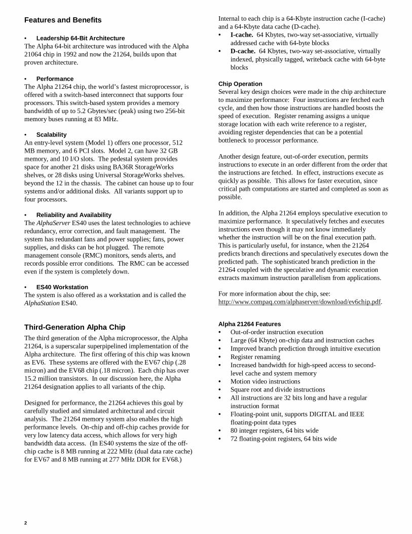
Features and Benefits
• Leadership 64-Bit ArchitectureThe Alpha 64-bit architecture was introduced with the Alpha21064 chip in 1992 and now the 21264, builds upon thatproven architecture.
• PerformanceThe Alpha 21264 chip, the world’s fastest microprocessor, isoffered with a switch-based interconnect that supports fourprocessors. This switch-based system provides a memorybandwidth of up to 5.2 Gbytes/sec (peak) using two 256-bitmemory buses running at 83 MHz.
• ScalabilityAn entry-level system (Model 1) offers one processor, 512MB memory, and 6 PCI slots. Model 2, can have 32 GBmemory, and 10 I/O slots. The pedestal system providesspace for another 21 disks using BA36R StorageWorksshelves, or 28 disks using Universal StorageWorks shelves.beyond the 12 in the chassis. The cabinet can house up to foursystems and/or additional disks. All variants support up tofour processors.
• Reliability and AvailabilityThe AlphaServer ES40 uses the latest technologies to achieveredundancy, error correction, and fault management. Thesystem has redundant fans and power supplies; fans, powersupplies, and disks can be hot plugged. The remotemanagement console (RMC) monitors, sends alerts, andrecords possible error conditions. The RMC can be accessedeven if the system is completely down.
• ES40 WorkstationThe system is also offered as a workstation and is called theAlphaStation ES40.
Third-Generation Alpha ChipThe third generation of the Alpha microprocessor, the Alpha21264, is a superscalar superpipelined implementation of theAlpha architecture. The first offering of this chip was knownas EV6. These systems are offered with the EV67 chip (.28micron) and the EV68 chip (.18 micron). Each chip has over15.2 million transistors. In our discussion here, the Alpha21264 designation applies to all variants of the chip.
Designed for performance, the 21264 achieves this goal bycarefully studied and simulated architectural and circuitanalysis. The 21264 memory system also enables the highperformance levels. On-chip and off-chip caches provide forvery low latency data access, which allows for very highbandwidth data access. (In ES40 systems the size of the off-chip cache is 8 MB running at 222 MHz (dual data rate cache)for EV67 and 8 MB running at 277 MHz DDR for EV68.)
Internal to each chip is a 64-Kbyte instruction cache (I-cache)and a 64-Kbyte data cache (D-cache).• I-cache. 64 Kbytes, two-way set-associative, virtually
addressed cache with 64-byte blocks• D-cache. 64 Kbytes, two-way set-associative, virtually
indexed, physically tagged, writeback cache with 64-byteblocks
Chip OperationSeveral key design choices were made in the chip architectureto maximize performance: Four instructions are fetched eachcycle, and then how those instructions are handled boosts thespeed of execution. Register renaming assigns a uniquestorage location with each write reference to a register,avoiding register dependencies that can be a potentialbottleneck to processor performance.
Another design feature, out-of-order execution, permitsinstructions to execute in an order different from the order thatthe instructions are fetched. In effect, instructions execute asquickly as possible. This allows for faster execution, sincecritical path computations are started and completed as soon aspossible.
In addition, the Alpha 21264 employs speculative execution tomaximize performance. It speculatively fetches and executesinstructions even though it may not know immediatelywhether the instruction will be on the final execution path.This is particularly useful, for instance, when the 21264predicts branch directions and speculatively executes down thepredicted path. The sophisticated branch prediction in the21264 coupled with the speculative and dynamic executionextracts maximum instruction parallelism from applications.
For more information about the chip, see:http://www.compaq.com/alphaserver/download/ev6chip.pdf.
Alpha 21264 Features• Out-of-order instruction execution• Large (64 Kbyte) on-chip data and instruction caches• Improved branch prediction through intuitive execution• Register renaming• Increased bandwidth for high-speed access to second-
level cache and system memory• Motion video instructions• Square root and divide instructions• All instructions are 32 bits long and have a regular
instruction format• Floating-point unit, supports DIGITAL and IEEE
floating-point data types• 80 integer registers, 64 bits wide• 72 floating-point registers, 64 bits wide

3
Model VariantsAlphaServer ES40 systems are offered in two models. Theentry-level model provides connectors for four DIMMs oneach of the memory motherboards (MMBs) and connectors forsix PCI options on the PCI backplane.
Model 1 Model 21–4 CPUs 1–4 CPUsUp to 16 GB memory Up to 32 GB memory6 PCI slots 10 PCI slots
To upgrade from Model 1, you replace the PCI backplane andthe four memory motherboards. A Model 2 system has eightDIMMs on each MMB (32 total) and 10 PCI slots.
CPU UpgradesUpgrading from the 500 to 667 or 883 MHz processorsrequires that the system board (54-25385-01) be a minimumrevision of E05.
System PackagingAll system variants use the same chassis, with space for twodisk cages in the front. Each cage holds up to six 1-inchUltra3 SCSI disks.
The chassis has a compartment for the CPUs and memory andanother one for the PCI I/O cards. The control panel, CD-ROMand floppy drives, and two additional removable media bays arein the front, along with space for up to two disk cages. Thepower supplies are in the rear.
Chassis, Pedestal ViewAdditional storage is available in the pedestal enclosure. Thechassis is mounted over a box that can house up to three BA36RStorageWorks shelves (two in the front and one in the rear), orup to two Ultra3 Universal (single-bus or split-bus)StorageWorks shelves.
PK3243
CPUs andMemory
IO
Fans
Control Paneland Drives
Fans
Chassis, Tower ViewIn the tower enclosure, the chassis is rotated 90 degrees, withthe control panel and removable media bays keeping theirsame horizontal position as in the pedestal/rack system.
PK3245
Rackmount ChassisWhen installed in a cabinet, the chassis has the sameorientation as that used in the pedestal. The chassis can bemounted in the 67-inch or 79-inch M-series cabinet, which is a19-inch wide RETMA cabinet. Each system requires 14inches (8U) of vertical space. With the maximum number ofsystems in a cabinet (four), there can be two StorageWorksshelves. When the maximum number of disks is desired (sixshelves), there can be three systems. (These numbers are forthe H9A15 79-inch cabinet.)
4
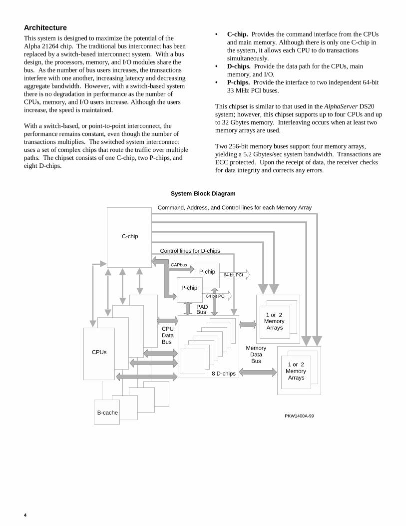
ArchitectureThis system is designed to maximize the potential of theAlpha 21264 chip. The traditional bus interconnect has beenreplaced by a switch-based interconnect system. With a busdesign, the processors, memory, and I/O modules share thebus. As the number of bus users increases, the transactionsinterfere with one another, increasing latency and decreasingaggregate bandwidth. However, with a switch-based systemthere is no degradation in performance as the number ofCPUs, memory, and I/O users increase. Although the usersincrease, the speed is maintained.
With a switch-based, or point-to-point interconnect, theperformance remains constant, even though the number oftransactions multiplies. The switched system interconnectuses a set of complex chips that route the traffic over multiplepaths. The chipset consists of one C-chip, two P-chips, andeight D-chips.
• C-chip. Provides the command interface from the CPUsand main memory. Although there is only one C-chip inthe system, it allows each CPU to do transactionssimultaneously.
• D-chips. Provide the data path for the CPUs, mainmemory, and I/O.
• P-chips. Provide the interface to two independent 64-bit33 MHz PCI buses.
This chipset is similar to that used in the AlphaServer DS20system; however, this chipset supports up to four CPUs and upto 32 Gbytes memory. Interleaving occurs when at least twomemory arrays are used.
Two 256-bit memory buses support four memory arrays,yielding a 5.2 Gbytes/sec system bandwidth. Transactions areECC protected. Upon the receipt of data, the receiver checksfor data integrity and corrects any errors.
System Block Diagram
C-chip
FirstCPU
8 D-chips
P-chip
P-chip
1 or 2MemoryArrays
MemoryArrays
64 bit PCI
64 bit PCI
Command, Address, and Control lines for each Memory Array
Control lines for D-chips
MemoryDataBus
CPUDataBus
CAPbus
PADBus
PKW1400A-99
1 or 2
CPUs
B-cache

5
System BoardThe interconnect switch is implemented on the system boardby the chipset consisting of one C-chip, two P-chips, and eightD-chips. This complex chipset provides the data and addresspath between the CPUs, memory, and the I/O subsystem.
A flash ROM holds the console code and the NVRAM data.
Connectors are provided for four CPU modules and fourmemory motherboards.
One corner of the board holds logic for the remotemanagement console (RMC).
On the back side of the module are connectors for the powersupplies. The I/O connector provides both signals and powerto the PCI backplane.
Component and Connector Locations
PK-0323-99
MMB1
MMB3
MMB0
MMB2
J7
J8
J5
J6
CPU3
CPU2
CPU1
CPU0
J17
J18
J34
J40
D-chip
P-chip P-chip
Connector to I/O
C-chip
D-chip D-chip
D-chipD-chipD-chipD-chip
D-chip
RMC Corner
6
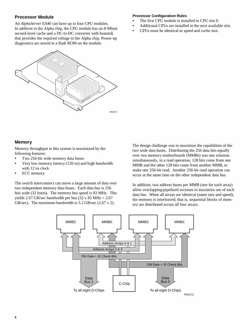
Processor ModuleAn AlphaServer ES40 can have up to four CPU modules.In addition to the Alpha chip, the CPU module has an 8-Mbytesecond-level cache and a DC-to-DC converter with heatsinkthat provides the required voltage to the Alpha chip. Power-updiagnostics are stored in a flash ROM on the module.
PK0271
Processor Configuration Rules• The first CPU module is installed in CPU slot 0.• Additional CPUs are installed in the next available slot.• CPUs must be identical in speed and cache size.
MemoryMemory throughput in this system is maximized by thefollowing features:• Two 256-bit wide memory data buses• Very low memory latency (120 ns) and high bandwidth
with 12 ns clock• ECC memory
The switch interconnect can move a large amount of data overtwo independent memory data buses. Each data bus is 256bits wide (32 bytes). The memory bus speed is 83 MHz. Thisyields 2.67 GB/sec bandwidth per bus (32 x 83 MHz = 2.67GB/sec). The maximum bandwidth is 5.2 GB/sec (2.67 x 2).
The design challenge was to maximize the capabilities of thetwo wide data buses. Distributing the 256 data bits equallyover two memory motherboards (MMBs) was one solution:simultaneously, in a read operation, 128 bits come from oneMMB and the other 128 bits come from another MMB, tomake one 256-bit read. Another 256-bit read operation canoccur at the same time on the other independent data bus.
In addition, two address buses per MMB (one for each array)allow overlapping/pipelined accesses to maximize use of eachdata bus. When all arrays are identical (same size and speed),the memory is interleaved; that is, sequential blocks of mem-ory are distributed across all four arrays.
256 Data + 32 Check Bits
DataBus 0
MMB2 MMB0 MMB3 MMB1
256 Data + 32 Check Bits
Address Arrays 2 & 3
Address Arrays 0 & 1
DataBus 1 C-Chip
To all eight D-ChipsTo all eight D-ChipsPK0272

7
Memory OptionsEach memory option consists of four 200-pin industry-standard DIMMs. The DIMMs are synchronous DRAMs.The Model 1 system supports up to four memory options (16DIMMs), and the Model 2 system supports up to eight options(32 DIMMs). Memory options are available in the followingsizes:• 512 Mbytes (128 MB DIMMs)• 1 Gbyte (256 MB DIMMs)• 2 Gbytes (512 MB DIMMs)• 4 Gbytes (1 GB DIMMs)
With the 4 GB option, Model 1 supports 16 GB memory andModel 2 supports 32 GB memory.
Memory Motherboard
PK-0324-99
1
2
34
56
78
Memory ConfigurationA memory option (or set) consists of four DIMMs, and allfour DIMMs must be the same size.• Fill sets in numerical order. Populate all 4 slots in Set 0,
then populate Set 1, and so on.• An array is one set for systems that support 16 DIMMs
and two sets for systems that support 32 DIMMs.• DIMMs in an array must be the same size and type. For
example, suppose you have populated Sets 0, 1, 2, and 3.When you populate Set 4, the DIMMs must be the samesize and type as those installed in Set 0. Similarly, Set 5must be populated with the same size and type of DIMMsas are in Set 1, and so on, as indicated in the followingtable.
Array Model 1 System Model 2 System0 Set 0 Set 0 and Set 41 Set 1 Set 1 and Set 52 Set 2 Set 2 and Set 63 Set 3 Set 3 and Set 7
• Systems that require full redundant power (three powersupplies) are restricted to a maximum of 24 Gbytesmemory.
Memory Performance ConsiderationsWith one memory option (4 DIMMs) installed in either Model1 or Model 2, memory operation interleaving will not occur.With two memory options (8 DIMMs), memory read-writeoperations are two-way interleaved. Interleaved operationsreduce the average latency and increase the memory through-put over noninterleaved operations. With four memoryoptions (16 DIMMs) installed, memory read-write operationsare four-way interleaved, maximizing memory throughput.
Memory Arrays and Sets on Memory Motherboards
11335577
00224466
11335577
00224466
Array 0Sets 0 & 4
Array 1Sets 1 & 5
Array 2Sets 2 & 6
Array 3Sets 3 & 7
Sets
Sets
Sets
Sets
PK0330-99
MMB 2
MMB 0
MMB 3
MMB 1

8
System I/OTwo industry-standard PCI I/O buses allow you to useinexpensive, widely available I/O options. Both 32-bit and64-bit PCI options can be used; 3.3V and 5V options aresupported.
The industry-standard PCI bus is the number one choice forhigh-performance I/O options, such as disk storage and high-performance video applications.
The PCI bus implementation has the following characteristics:• Fully compliant with the PCI Version 2.1 Specification• Operates at 33 MHz, delivering a peak bandwidth of 500
MB/sec; over 250 Mbytes/sec for each PCI bus• 6 option slots (Model 1) or 10 option slots (Model 2)• Supports three address spaces: PCI I/O, PCI memory, and
PCI configuration space• Supports byte/word, tri-byte, and longword operations• Exists in noncached address space only
Block Diagram of I/O Control
PK-0319A-98
P-chip 0
Flash ROM
Interrupts
Acer Labs1543C Chip
Config
(NVRAM functions)
P-chip 1
KeyboardMouseCD-ROMUSB
COM1COM2ModemPrinterFloppy
PCI 0
PCI 1
PCI Slot
PCI Slot
C-chip
I/O ImplementationIn a Model 2 system that has 10 I/O slots, PCI 0 has 4 slots,and PCI 1 has 6 slots. In a Model 1 system with 6 slots, eachPCI has 3 slots.
The Acer Labs 1543C chip provides the bridge from PCI 0 toISA. The C-chip controls accesses to memory on behalf ofboth P-chips.
I/O Configuration RulesA VGA controller, if present, must be installed in PCI 0.
I/O PortsAt the rear of the system are connectors offering access to twoserial communications ports, one modem port for the remotemanagement console, one parallel port, ports for the keyboardand mouse, and two USB ports. Two SCSI breakouts are alsoon the back panel.
Pedestal/Rack
PK-0325-99
1 2 3 4 5 6 7
8
1. RMC modem port 2. COM2 serial port 3. Keyboard port 4. Mouse port 5. COM1 serial port 6. USB ports 7. Parallel port 8. SCSI breakouts

9
System ControlClose monitoring and control of the system environment andhardware is done by the remote management console (RMC).This logic also allows the system operator to monitor the sys-tem from a remote location. The RMC logic is implementedusing a PIC17C44 microprocessor on the system board. TheRCM firmware code resides on the microprocessor and inflash memory. The RMC is powered by an auxiliary 5V sup-ply, so even when the system is powered off at the controlpanel the RMC can be accessed—so long as the system isplugged in.
The RMC provides the following monitoring and controlfunctions:• Monitors thermal sensors on the CPUs, the PCI
backplane, and the power supplies• Monitors voltages, power supplies, and fans• Handles hot swapping of power supplies and fans• Controls the control panel display and writes status
messages on the display• Detects alert conditions such as excessive temperature,
fan failure, and power supply failure and sends an alert• Shuts down the system if any fatal conditions exist• Records error log information in nonvolatile RAM on
each failing device
StorageRemovable media in the chassis includes a CD-ROM drive,floppy diskette drive, and two 5.25 inch half-height bays,which can be combined for one 5.25 inch full-height bay.
A disk cage in the front of the chassis supports up to six Ultra3SCSI Universal 1-inch disk drives (9.1, 18.2, or 36.4 GB).The drives are available at 10,000 or 15,000 RPM. Anotherdisk cage can be added so that up to twelve disks can beinstalled. Each cage requires its own SCSI adapter.
Storage shelves can be either BA36R StorageWorks shelves orUltra3 Universal StorageWorks shelves. The BA36RStorageWorks shelf supports seven disks per shelf; the Ultra3Universal StorageWorks shelf supports 7 disks (single-bus) or14 disks (split-bus) per shelf.
The pedestal system can include:• Up to three BA36R StorageWorks shelves• Up to two Ultra3 Universal StorageWorks shelves
(single-bus or split-bus)
The rackmount cabinet can include:• Up to six BA36R StorageWorks shelves• Up to eight Ultra3 Universal StorageWorks shelves
Fibre ChannelAvailable on these AlphaServer systems is the next storageinterface, Fibre Channel, which eliminates issues with today’sSCSI interfaces such as distance, bandwidth, scalability, andreliability. Fibre Channel (FC) is the answer to not onlyserver-to-storage connections but also to server-to-servernetworking, because multiple protocols are supported. SCSI,TCP/IP, video, or raw data can all take advantage of high-performance, reliable Fibre Channel technology.
With the KGPSA PCI Fibre Channel adapter, the ES40systems provide a storage interconnect that is 2.5 times as fastas UltraSCSI: 100 vs 40 Mbytes/sec data throughput. TheKGPSA adapter allows you to manage storage including theHSG80 RAID controller in a switched FC topology.
RAID (Redundant Array of Independent Disks)The system can be configured with optional PCI RAIDcontrollers to organize disk data cost-effectively, improveperformance, and provide high levels of storage integrity.Today, RAID is only available with StorageWorks shelves.
The optional RAID controllers have the following features:• Support for hot-swap drives• Automatic rebuild after hot swap• Console support for booting system from RAID• RAID levels 0, 1, 0+1, 5• Optional write cache• Optional read cache• Support for command queuing
Server ManagementThe AlphaServer products support important operational andplatform management requirements.
Operational ManagementServer/Network Management. Compaq Insight Manager isincluded with every system. This software tool allows you tomonitor and control Alpha based servers. Insight Managerconsists of two components: a Windows-based console appli-cation and server- or client-based management data collectionagents. Management agents monitor over 1,000 managementparameters. Key subsystems are instrumented to make health,configuration, and performance data available to the agentsoftware. The agents act upon that data, by initiating alarms inthe event of faults and by providing updated management in-formation, such as network interface or storage subsystem per-formance statistics.
Remote Server Management. The integrated remote manage-ment console (RMC) lets the operator perform several tasksfrom a serial console: monitor the system power, temperature,and fans, and reset, halt, and power the system on or off. Themonitoring can be done locally or remotely through a modem.

10
Platform ManagementThe AlphaServer ES40 systems support platform managementtasks such as manipulating and monitoring hardware perform-ance, configuration, and errors. For example, the operatingsystems provide a number of tools to characterize system per-formance and display errors logged in the system error log file.
In addition, system console firmware provides hardware con-figuration tools and diagnostics to facilitate quick hardwareinstallation and troubleshooting. The system operator can usesimple console commands to show the system configuration,devices, boot and operational flags, and recorded errors. Also,the console provides inventory support and configurationmanagement by giving access to serial numbers and revisionsof hardware and firmware.
Error ReportingCompaq Analyze, a diagnostic service tool used to determinethe cause of hardware failures, is installed with the operatingsystems. It provides automatic background analysis, as itconstantly views and reads the error log file. It analyzes bothsingle error/fault events and multiple events. When an errorcondition is detected, it collects the error information andsends it and an analysis to the user. The tool requires agraphics monitor for its output display.
Security• Front doors can be locked to prevent access to the disk
drives and the rest of the system.• An interlock sensor switch shuts down power if the top
cover to the CPU/memory area is removed while power ison.
• Password protection is offered by the SRM console andRMC.
Reliability and Availability FeaturesThe AlphaServer ES40 system achieves an unparalleled levelof reliability and availability through the careful application oftechnologies that balance redundancy, error correction, andfault management. Reliability and availability features arebuilt into the CPU, memory, and I/O, and implemented at thesystem level.
Processor Features• CPU data cache provides error correction code (ECC)
protection.• Parity protection on CPU cache tag store.• Multi-tiered power-up diagnostics to verify the
functionality of the hardware.When you power up or reset the system, each CPU, in parallel,runs a set of diagnostic tests. If any tests fail, the failing CPUis configured out of the system. Responsibility for initializingmemory and booting the console firmware is transferred toanother CPU, and the boot process continues. This featureensures that a system can still power up and boot the operatingsystem in case of a CPU failure. Messages on the operatorcontrol panel power-up/diagnostic display indicate the teststatus and component failure information.
Memory Features• The memory ECC scheme is designed to provide maxi-
mum protection for user data. The memory schemecorrects single-bit errors and detects double-bit errors andtotal DRAM failure.
• Memory failover. The power-up diagnostics are designedto provide the largest amount of usable memory, config-uring around errors.
I/O Features• ECC protection on the switch interconnect and parity
protection on the PCI and SCSI buses.• Extensive error correction built into disk drives.• Optional internal RAID improves reliability and data
security.• Disk hot swap.
System FeaturesAuto reboot. On systems running Tru64 UNIX or OpenVMS, afirmware environment variable lets you set the default actionthe system takes on power-up, reset, or after an operatingsystem crash. For maximum system availability, the variablecan be set to cause the system to automatically reboot theoperating system after most system failures.
Software installation. The operating systems are factoryinstalled. Factory installed software (FIS) allows you to bootand use your system in a shorter time than if you install thesoftware from a distribution kit.
Diagnostics. During the power-up process, diagnostics arerun to achieve several goals:• Provide a robust hardware platform for the operating
system by ensuring that any faulty hardware does notparticipate in the operating system session. This maxi-mizes system uptime by reducing the risk of systemfailure.
• Enable efficient, timely repair.Audible beep codes report the status of diagnostic testing.The system has a firmware update utility (LFU) that providesupdate capability for console and PCI I/O adapter firmware.A fail-safe loader provides a means of reloading the console inthe event of corrupted firmware.
Thermal management. The air temperature and fan operationare monitored to protect against overheating and possiblehardware destruction. Six fans provide front to back cooling,and the power supplies, in the rear, have their own fans. If thetemperature rises, the system fans speed up; or if necessary toprevent damage, the system shuts down. If the main fan, whichcools the system card cage, fails, a redundant fan takes over.

11
Error handling. Parity and other error conditions are detectedon the PCI buses. The memory checking scheme correctssingle-bit errors and detects double-bit errors. Multiple ECCcorrections to single-bit errors detected by the operatingsystems help in determining where in the system the errororiginated. Errors are logged for analysis.
Disk hot swap. The hardware is designed to enable hot swapof disks. Hot swap is the removal of a disk while the rest ofthe system remains powered on and continues to operate. Thisfeature contributes significantly to system availability. Sincemany disk problems can be fixed without shutting down theentire system, users lose access only to the disks that areremoved.
N+1 power redundancy. A second or third power supply canbe added to provide redundant power to the chassis. A secondpower supply is needed for more than two CPUs or if a seconddisk cage is installed. In this case the third supply providesredundancy. The third power supply provides full N+1 redun-dancy for configurations using up to 24 Gbytes memory.Power supplies are 720 watts (DC). Each has two LEDs toindicate the state of power to the system.
An external UPS can be purchased to support critical customerconfigurations. Because power is maintained for the entiresystem (CPU, memory, and I/O), power interruptions arecompletely transparent to users.
Installation and MaintenanceThe systems are designed for easy hardware, software, andoption installation. Options ordered with a system are pre-installed and tested at the factory. The operating systems arealso installed at the factory.
Additional CPUs, memory, power supplies, and disks can beadded to the tower and pedestal systems by anyone withappropriate technical training and experience. Installation ofcomponents in a rackmount system is reserved for serviceproviders and self-maintenance customers.
ClusteringA cluster is a loosely coupled set of systems that behaves (isaddressed and managed) like a single system, but provideshigh levels of availability through redundant CPUs, storage,and data paths. Clusters are also highly scalable; that is, CPU,I/O, storage, and application resources can be added incre-mentally to efficiently increase capacity. For customers, thistranslates to reliable access to system resources and data, andinvestment protection of both hardware and software.
Clustering allows multiple computer systems to communicateover a common interface, share disks, and spread the comput-ing load across multiple CPUs. Clustering is implementedusing our traditional interconnects and using the newest tech-nology.
PCI to Memory Channel InterconnectUnder Tru64 UNIX and OpenVMS, you can build high-avail-ability clusters using the PCI to Memory Channel intercon-nect. The Memory Channel interconnect is a high-bandwidth,low-latency PCI-based communications interconnect for up toeight AlphaServer systems. Data written to one computer'smemory is shared by other computers on the Memory Channelbus.
The PCI adapter is the interface between a PCI and a MemoryChannel bus. This bus is a memory-to-memory computersystem interconnect that permits I/O space writes in onecomputing node to be replicated into the memories of all othernodes on the Memory Channel bus. A write performed by anyCPU to its reflected address region results in automatichardware updates to memory regions in other nodes. Onenode’s write is “reflected” to other nodes as a direct side effectof the local write. This provides a memory region withproperties similar to a high-performance shared memoryacross a group of nodes.
Operating System SupportFor clustered Tru64 UNIX systems, TruCluster Softwaresolutions allow users access to network services and providefurther failover recovery from server, network, or I/O failures.Tru64 UNIX cluster systems use the SCSI bus and/or PCI toMemory Channel interconnect bus between disks and systems.
OpenVMS cluster systems use the CI, SCSI, Ethernet, FDDI,and Memory Channel as the interconnect between disks andsystems.
The primary means of clustering AlphaServer ES40 systemsdepends on the operating system.• CI clusters, OpenVMS only• Memory Channel, Tru64 UNIX and OpenVMS• SCSI clusters, Tru64 UNIX and OpenVMS

12
Performance and BenchmarkingCompaq has an ongoing program of performance engineering,using industry-standard benchmarks that allow comparisonsacross major vendors’ systems. These benchmarks againstcompetitive systems are based on comparable CPU perform-ance, coupled with comparable memory and disk expand-ability.
See Table 1 for the record-breaking performance numbers ofthe AlphaServer ES40 systems
System performance, however, is highly dependent uponapplication characteristics. Thus, benchmark information isone helpful “data point” to be used in conjunction with otherpurchase criteria such as features, service, and price.
Sources of Performance InformationPerformance information is available on the Internet.http://www.compaq.com/alphaserver/performance/index.htmlhttp://www.ideasinternational.com/benchmark/spec/specfp_s2000.html
Information for Compaq PartnersIf you are a Channel or Reseller Partner, you can find the tools,resources, and information you need to conduct Compaq busi-ness online on the secure Compaq Partner Network extranet site:http://CPN.compaq.com
Also see the Compaq Solutions Alliance site athttp://csa.compaq.com
Service and SupportCompaq provides a comprehensive set of services thatrange from migration, consulting, and training, to directsupport of Alpha systems, software, and applications. Forinformation on Compaq Services, point your Web browser tohttp://www.compaq.com/services.
Hardware WarrantyThe AlphaServer ES40 system and components, includingCPU, memory, PCI controllers, and power supplies, have a3-year on-site, 5-day per week, 9-hour per day hardwarewarranty with next-day response time.
StorageWorks components contained in the pedestal or cabinetsystems are supported by the comprehensive StorageWorkswarranty: five years for disks, three years for controllers, twoyears for tape devices, and one year for other components. Thefirst year includes on-site next-day response time. Networkproducts in the pedestal or cabinet systems carry the networkproducts warranty.
Users can upgrade to higher levels of service through a varietyof hardware supplemental services.
Software WarrantyThe warranty for Tru64 UNIX and OpenVMS is conformanceto SPD with advisory telephone support for a period of 90days. Users can upgrade to higher levels of service through avariety of software supplemental services.
13
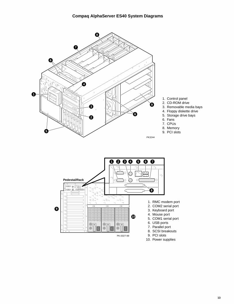
Compaq AlphaServer ES40 System Diagrams
6
7
8
1
5
3
26
4
PK3244
9
1. Control panel 2. CD-ROM drive 3. Removable media bays 4. Floppy diskette drive 5. Storage drive bays 6. Fans 7. CPUs 8. Memory 9. PCI slots
Pedestal/Rack
PK-0327-99
1 2 3 4 5 6 7
8
1. RMC modem port 2. COM2 serial port 3. Keyboard port 4. Mouse port 5. COM1 serial port 6. USB ports 7. Parallel port 8. SCSI breakouts 9. PCI slots10. Power supplies
9
10

14
System Features at a GlanceTable 1 provides a quick reference to features of the Compaq AlphaServer ES40 systems.
Table 1 AlphaServer ES40 Features
System Features
CPU features 6/667 6/833Symmetric multiprocessing 1–4 processors 1–4 processorsCPU clock speed Alpha 21264A / 667 MHz Alpha 21264A / 833 MHzCache size (on chip/on board) 64 KB I, 64 KB D / 8 MB ECC DDR 64 KB I, 64 KB D / 8 MB ECC DDR
Memory (maximum) 16 GB in Model 1 and 32 GB in Model 2 *
67/667 68/833
Performance 1 CPU 2 CPUs 4 CPUs 1 CPU 2 CPUs 4 CPUs
SPECint2000 433 544SPECfp2000 562 658SPECint_rate2000 5.05 10.3 19.8 6.31 12.5 24.7SPECfp_rate2000 6.50 12.2 21.9 7.63 14.0 25.5SPECweb99 2,304SPECjvm98 71.9 83.5 100 104SPECjbb2000 23,787 15,152 28,032SPECsfs97 .v3 14,157TPC-C 30,738 tpmC @ $29
Standard Features 1.44 MB diskette drive, CD-ROM drive, 1 RMC dedicated serial port, 2 serial ports, 1 parallel port,keyboard and mouse, integrated remote system management console, operating system license andcustomer documentation, Internet software
Storage
Removable media CD-ROM, floppy diskette, two HH 5.25” removable media baySystem chassis storage 12 disks (437 GB with 36.4 GB disks) Ultra3 SCSIPedestal Disk Drive Cages PLUS BA36R StorageWorks Shelves OR Universal StorageWorks Split-Bus Shelves
12 disks (437 GB @ 36.4 GB) 21 disks (764 GB @ 36.4 GB) 28 disks (1 TB @ 36.4 GB)Total capacity: 1.2 TB Total capacity: 1.5 TB
H9A10 cabinet Disk Drive Cages BA36R StorageWorks Shelves Universal StorageWorks Split-Bus Shelves24 disks (874 GB @ 36.4 GB) 42 disks (1.5 TB @ 36.4 GB) 112 disks (4 TB @ 36.4 GB)
Total capacity: 2.4 TB Total capacity: 4.9 TBH9A15 cabinet Disk Drive Cages BA36R StorageWorks Shelves Universal StorageWorks Split-Bus Shelves
36 disks (1.3 TB @ 36.4 GB) 42 disks (1.5 TB @36.4 GB) 112 disks (4 TB @ 36.4 GB)Total capacity: 2.8 TB Total capacity: 5.4 TB
I/O System
I/O slots 6 PCI slots in Model 1 or 10 PCI slots in Model 2Maximum PCI throughput Over 500 MB/sec with two 256 MB/sec buses
High Availability Features
System System auto reboot, thermal management, remote system management, RAID 0, 1, 0+1, 5, hot swap ofdisks, power supplies, and fans, memory failover, ECC memory, ECC cache, N+1 power supply,*SMP CPU failover, error logging, optional uninterruptible power supply
OpenVMS clusters CI, Ethernet, SCSI, FDDI, PCI to Memory Channel InterconnectTru64 UNIX TruClusters Solutions SCSI, PCI to Memory Channel Interconnect
Operating Systems Tru64 UNIX, OpenVMS, Linux
Warranty
Hardware 3-year, on-site, 5 day x 9 hour warranty with 24-hour responseSoftware 90-day telephone advisory support for OpenVMS and Tru64 UNIX
* Configurations requiring N+1 redundant power are restricted to a maximum of 24 Gbytes memory; if full redundancy is not required,32 Gbytes memory is supported.

15
Physical CharacteristicsTable 2 details basic physical characteristics of the system,and Table 3 gives the electrical characteristics.
Table 2 AlphaServer ES40 Physical CharacteristicsDimensions Tower Pedestal RackmountHeight 50.8 cm (20.0 in.) 78.2 cm (30.8 in.) 35.2 cm (13.87 in.)Width 38.7 cm (15.25 in.) 50.8 cm (20.0 in.) 44.7 cm (17.6 in.)Depth 78.7 cm (31.0 in.) 80.6 cm (31.75 in.) 76.5 cm (30.1 in.)Weight 65 kg (143 lb) typical;
96 kg (211 lb) maximum127 kg (280 lb) typical;159 kg (350 lb) maximum
With brackets, slides, & cablesNominal 59 kg (130 lb)Maximum 92 kg (202 lb)
Environmental
Temperature OperatingStorage (60 days)Rate of change
10–35° C (50–95° F)–40 to 66° C (–40 to 151° F)11° C/hr (20° F/hr)
Relative humidity OperatingNonoperatingStorage (60 days)Rate of change
20–80%20–80%10–95%20%/hr.
Maximum wet bulb temperature OperatingStorage (60 days)
28° C (82° F)46° C (115° F)
Minimum dew point temperature Operating 2° C (36° F)Heat dissipationTower and RackPedestalH9A10/H9A15
Nominal900 w, 3074 BTU/hr1480 w, 5054 BTU/hrConfiguration dependent
Maximum1300 w, 4440 BTU/hr2400 w, 8196 BTU/hr4800 w, 16392 BTU/hr
Airflow and quality Intake locationExhaust location
FrontRear–Tower, Pedestal, RackRear/Top–H9A10/H9A15
Altitude OperatingNonoperating
3037 m (10,000 ft)12,190 m (40,000 ft)
Vibration Operating 10–500 Hz .1 G peakMechanical shock Operating
Tower/PedestalM-Series Cabinet
7.5 G, 10 +/– 3ms5.0 G, 10 +/– 3ms
Acoustics—Declared values per ISO 9296 and ISO 7779Current values for specific configurations are available from Compaq. 1 B = 10 dBA
AcousticsIdleOperating
LWad , B6.66.6
LpAm , dBA (bystander position)4848
Table 3 AlphaServer ES40 Electrical CharacteristicsNominal voltage (Vac)Voltage range (Vac)temporary condition)
Power source phaseNominal frequency (Hz)Frequency range (Hz)RMS current (max. steady state)
Tower and RackmountSingle power cordMultiple power cords
PedestalEach power cord
M-Series cab config.-dependentNominal voltage (Vac)Each power cord
100 120 200–24090–110 110–128 180–250
Single Single Single50/60 50/60 50/6049–51/59–61 49–51/59–61 49–51/59–61
11.0 A 8.5 A 5.0 A6.5 A 5.3 A 3.0 A
12.0 A 10.5 A 7.0 A
100 120 220–24024 A 24 A 16 A
NOTE: Power supplies are universal, PFC, auto ranging, 100 / 120 / 200–240 Vac.

© 2001 Compaq Computer Corporation
Compaq, the Compaq logo, Compaq Insight Manager, AlphaServer,StorageWorks, and TruCluster Registered in U.S. Patent and TrademarkOffice. OpenVMS and Tru64 are trademarks of Compaq InformationTechnologies Group, L.P. in the United States and other countries.
Linux is a registered trademark of Linus Torvalds in several countries.UNIX is a trademark of The Open Group in the United States and othercountries. All other product names mentioned herein may be trademarks oftheir respective companies.
Compaq shall not be liable for technical or editorial errors or omissionscontained herein. The information in this document is provided “as is”without warranty of any kind and is subject to change without notice. Thewarranties for Compaq products are set forth in the express limited warrantystatements accompanying such products. Nothing herein should be construedas constituting an additional warranty.