Embed Size (px)
Citation preview

Approved: ………………………….. Chief Engineer
Issue No 3 3132547
21 March 2018 Page 1 of 45
Company Standard
NMST-030
Installation Connection

Installation Connection NMST-030
Company Standard
Approved by Chief Engineer
Issue No 3 3132547
21 March 2018 Page 2 of 45
Contents 1. PURPOSE .................................................................................................................. 5
2. DEFINITIONS ............................................................................................................. 5
3. CONNECTIONS GENERAL ....................................................................................... 8 3.1 Contract Supply Capacity ................................................................................................................................... 8 3.2 Domestic Connections ...................................................................................................................................... 10 3.3 Network Connection Point ................................................................................................................................ 11 3.4 LV Connections .................................................................................................................................................. 11 3.5 High Voltage Connection .................................................................................................................................. 12 3.6 Multiple Connections ......................................................................................................................................... 12 3.7 Line Charges ....................................................................................................................................................... 12
3.7.1 General ................................................................................................................................................... 12 3.7.2 Off Peak Services ................................................................................................................................. 13 3.7.3 Domestic Line Charges ........................................................................................................................ 13 3.7.4 Multiple Metering Points....................................................................................................................... 14
3.8 Installation/Disconnection ................................................................................................................................. 14
4. OWNERSHIP BOUNDARIES AND RESPONSIBILITIES ........................................ 15 4.1 General Conditions ............................................................................................................................................ 15
4.1.1 Installation .............................................................................................................................................. 15 4.1.2 Network .................................................................................................................................................. 15
4.2 Voltage Levels .................................................................................................................................................... 16 4.3 Low Voltage Installations .................................................................................................................................. 16
4.3.1 Standard Single Installation Supply ................................................................................................... 16 4.3.2 Single Owner with Single Supply, but Multiple Metering Points .................................................... 17 4.3.3 Multiple ICPs/Installations within a Single Building- Single Network Connection ....................... 17 4.3.4 Multiple ICPs/Installations - Private Road ......................................................................................... 18
4.4 High Voltage Installations ................................................................................................................................. 18 4.4.1 General ................................................................................................................................................... 18 4.4.2 LV Installation with Tee’d Transformer .............................................................................................. 18 4.4.3 LV Installation with feed-through Substation .................................................................................... 19 4.4.4 LV Installation with remote feed-through switchgear and Tee’d Transformer ............................. 19 4.4.5 LV Installation with Tee’d Transformer and LV Interconnection .................................................... 19 4.4.6 HV Installation Connection .................................................................................................................. 20 4.4.7 HV Installation with Dedicated HV feeders ....................................................................................... 20 4.4.8 HV Installation with Feed-through ...................................................................................................... 20
5. APPLICATIONS AND APPROVALS ....................................................................... 21 5.1 Applications for Network Connection .............................................................................................................. 21 5.2 Installation Modifications ................................................................................................................................... 21 5.3 Approval to Connect .......................................................................................................................................... 22 5.4 Customer Connection Service Standards ...................................................................................................... 22
6. COSTS FOR A NEW NETWORK CONNECTION ................................................... 23
6.1 Cost Responsibilities ......................................................................................................................................... 23 6.2 Enhanced Supply ............................................................................................................................................... 23 6.3 Temporary Connection ...................................................................................................................................... 23
7. INSTALLATION LOADS .......................................................................................... 24

Installation Connection NMST-030
Company Standard
Approved by Chief Engineer
Issue No 3 3132547
21 March 2018 Page 3 of 45
7.1 Power Factor ....................................................................................................................................................... 24 7.2 Voltage Fluctuations .......................................................................................................................................... 24 7.3 Motor Starting ..................................................................................................................................................... 24
7.3.1 Exempt Motor Sizes ............................................................................................................................. 24 7.3.2 Non-Exempt Motors .............................................................................................................................. 25 7.3.3 Multiple Motor Installations .................................................................................................................. 25
7.4 Harmonic Disturbances ..................................................................................................................................... 25 7.5 Capacitors ........................................................................................................................................................... 26
8. MAINS ...................................................................................................................... 26
8.1 General Requirements ...................................................................................................................................... 26 8.2 Installation Livening ........................................................................................................................................... 26 8.3 Aerial Mains ........................................................................................................................................................ 27
8.3.1 General Conditions for all Aerial Mains ............................................................................................. 27 8.3.2 Special Conditions for LV Mains ......................................................................................................... 28 8.3.3 Special Conditions for Reconstructed Mains .................................................................................... 28
8.4 Underground LV Mains in Underground Reticulated Areas......................................................................... 29 8.4.1 Pillar Boxes ............................................................................................................................................ 29 8.4.2 Connection of Mains to Pillar Boxes .................................................................................................. 29
8.5 LV Underground Mains in an Overhead Area ................................................................................................ 29 8.5.1 Pole Top Supply .................................................................................................................................... 29 8.5.2 Pillar Box Supply ................................................................................................................................... 30
9. TRANSFORMERS OR SUBSTATIONS ON INSTALLATION OWNERS’ PREMISES ...................................................................................................................... 30
9.1 General Requirements ...................................................................................................................................... 30 9.2 Space Requirements ......................................................................................................................................... 31
9.2.1 Pole Substations ................................................................................................................................... 31 9.2.2 Kiosk Substation ................................................................................................................................... 32 9.2.3 Indoor Substations ................................................................................................................................ 32 9.2.4 Outdoor Ground Mounted Substations .............................................................................................. 32
10. INSTALLATION WITH GENERATION .................................................................... 32
11. FAULT LEVEL CONSIDERATIONS ........................................................................ 33 11.1 General ................................................................................................................................................................ 33 11.2 Contribution to Fault Level from within the Installation ................................................................................. 33
12. PROTECTION .......................................................................................................... 34 12.1 General ................................................................................................................................................................ 34 12.2 Protection of LV Mains Connected to LV Distribution Network ................................................................... 34 12.3 LV Connections from a Substation on an Installation Owner’s Property ................................................... 34
12.3.1 Transformers up to 300kVA ............................................................................................................ 34 12.3.2 Transformers greater than 300kVA without an LV Interconnection .......................................... 34 12.3.3 LV Supply from a Substation with an LV Interconnection .......................................................... 35
12.4 Protection of HV Connections .......................................................................................................................... 35 12.5 Unbalanced Voltage .......................................................................................................................................... 35 12.6 Ripple Receivers ................................................................................................................................................ 35
13. METERING ............................................................................................................... 35 13.1 General Metering Requirements ...................................................................................................................... 35

Installation Connection NMST-030
Company Standard
Approved by Chief Engineer
Issue No 3 3132547
21 March 2018 Page 4 of 45
13.2 Metering Requirements for All Installations .................................................................................................... 35 13.3 Metering Requirements for Installations with Contract Supply Capacity of 100kVA and Greater ......... 36
APPENDIX 1 - CAPACITY GUARANTEE AGREEMENT .............................................. 38
APPENDIX 2 - INSTALLATION CONNECTION APPLICATION FORM ........................ 40
APPENDIX 3 - MOTOR APPLICATION FORM .............................................................. 42
APPENDIX 4 - CUSTOMER CONNECTION SERVICE STANDARDS .......................... 43
APPENDIX 5 - AERIAL MAINS ARRANGEMENT ......................................................... 45

Installation Connection NMST-030
Company Standard
Approved by Chief Engineer
Issue No 3 3132547
21 March 2018 Page 5 of 45
1. PURPOSE
This standard defines the requirements for connection to PowerNet’s electricity Networks for the purpose of receiving a supply of electricity.
2. DEFINITIONS
Unless otherwise defined below, the terms used in this standard have meanings as defined in the Electricity Act 1992 and the Electricity Regulations 1997 and their subsequent amendments.
Any Time Demand - The maximum peak demand, in kVA, of the Installation.
Capacity Guarantee Agreement - Means an Agreement whereby a new Installation Owner agrees to pay for a certain Contract Supply Capacity for a specified period – Appendix 1.
Capital Contribution - Means a contribution from a new Installation Owner to cover the excess capital investment in the Network required to supply the Installation over the amount which is recovered through the line charges.
CBD - Central Business District - Means the main commercial area of Invercargill City.
Contract Supply Capacity - Means the maximum load in kVA the connection is designed to deliver.
Certificate of Compliance - Means the certificate issued by the electrician/inspector under Electricity legislation to confirm compliance with that legislation.
Connection Fee - A charge to recover the cost of processing the Installation Connection Application for a new connection.
Domestic Premises - Shall have the meaning defined in Section 90 of the Electricity Industry Reform Act 1998.
EIL - Electricity Invercargill Limited.
EGR - Electricity Governance Rules.
Electricity Regulations - The Electricity Regulations 1997 and subsequent amendments.
Electricity Retailer - Means an electricity retailer who has a valid Electricity Conveyance or Use of System Agreement with Electricity Invercargill Limited, The Power Company Limited, OtagoNet Joint Venture, or Electricity Southland Limited.
HV - High voltage - 1,000 volts or above.

Installation Connection NMST-030
Company Standard
Approved by Chief Engineer
Issue No 3 3132547
21 March 2018 Page 6 of 45
Installation - Means the electrical wiring in a building or similar for the purpose of being connected to the Network to receive a supply of electricity. Installation Owner - Means the Owner of, or person responsible for, the premises on which the Installation is located or the person responsible for the Installation.
Installation Connection Application Form - An example is shown in Appendix 2.
ICP - Installation Control Point - Means the point at which a consumer is supplied with electricity and at which the supply of electricity may flow between the Local Network and an Installation, where the Installation interconnects with an isolation device owned or controlled by the Distributor.
kVA - Kilovolt-ampere.
kVA Demand Metering - kVA Metering is required by PowerNet to obtain an annual demand and usage profile for line pricing purposes.
Line Charge - Charges imposed by PowerNet for provision of line function services and connection of an Installation to the Network.
Note - Line charges are charged to the consumer’s Electricity Retailer. That Electricity Retailer charges the consumer and may reconfigure the charges as they see fit.
LLN - Lakeland Network (An electricity network in the Wakatipu Basin owned by Electricity Southland Limited managed by PowerNet Limited).
Load Factor - Is defined as average load divided by the maximum load and is equal to the total kWh divided by the maximum demand multiplied by the number of hours in the prescribed period.
LV - Low voltage - up to 600 volts.
Mains - The cable or wiring of the Installation connecting between the Point of Supply and the main switchboard and/or Metering Point.
MCB - Main Circuit Breaker - (In the context of this document) A circuit breaker fitted on the switchboard to limit load of the Installation, it must be of an acceptable type and able to be sealed by PowerNet.
Metering Point - Means the location or locations in an Installation where the metering equipment is installed.
MVA – Megavolt ampere.
Network - Means the system for the conveyance of electricity including all fittings comprising that system owned by Electricity Invercargill Limited, The Power Company Limited, OtagoNet Joint Venture or Electricity Southland Limited and managed by PowerNet.

Installation Connection NMST-030
Company Standard
Approved by Chief Engineer
Issue No 3 3132547
21 March 2018 Page 7 of 45
Network Connection Point (NCP) - The point of connection of an Installation or Installations to the Network for the purpose of receiving an electricity supply.
OJV - OtagoNet Joint Venture (previously Otago Power Limited). Point of Common Coupling - Means the point of common coupling which is defined as the point in the Network, electrically nearest to the Installation at which other Installations are or may be connected.
Point of Supply (POS) - The demarcation point between the Network and the Property/Installation Owner’s ownership.
PowerNet - PowerNet Limited.
Property Owner - The owner of a property on which there is an Installation. The Property Owner may not necessarily be the Installation Owner, e.g. rental situations.
Ripple Control System - A facility involving broadcasting an electrical signal through the electricity network that can be received in an Installation by a device for the control of meters and/or electrical circuits, for the purpose of controlling the load on the network.
Ripple Receiver - A device in an Installation that receives the Ripple Control Signal and controls meters and/or electrical circuits.
Specific Ownership Agreement - A formal agreement between the Network owner and a Property/Installation Owner to establish private ownership of a line on private property that would normally be owned by the Network owner.
TOU Metering - TOU Metering measures the energy each half hour used by the whole Installation.
TPCL - The Power Company Limited.
All other definitions as per Electricity Regulations 1997.

Installation Connection NMST-030
Company Standard
Approved by Chief Engineer
Issue No 3 3132547
21 March 2018 Page 8 of 45
3. CONNECTIONS GENERAL
3.1 Contract Supply Capacity
The Contract Supply Capacity is the maximum electrical capacity of the Installation which the PowerNet Network is contracted and in most cases designed to supply. PowerNet will install service fuses at the ICP in accordance with the Contract Supply Capacity shown in the table below. Alternatively, the Contract Supply Capacity for larger installations is the next standard transformer size above the Anytime Demand of the Installation.
CONTRACT SUPPLY
CAPACITY
(NOMINAL)
MAXIMUM ICP FUSE SIZE PLUS OTHER
CAPACITY RESTRICTION IF REQUIRED
EIL/TPCL OJV
DOMESTIC
Small - 8kVA
(Single Phase only)
63 amp ICP Fuse
32 amp MCB on
Switchboard
N/A
Standard - Single Phase 63 amp ICP Fuse
80 amp on Special
Request
63 amp ICP Fuse
80 amp on Special
Request
Special - Multi Phase 2 or 3 x 63 amp ICP
Fuses
2 or 3 x 63 amp ICP
Fuses
Low User - 10% Fixed
Charge
As per Small, Standard or
Special
As Standard or Special
NON DOMESTIC SINGLE
PHASE
Streetlight
5 amp Fuse
5 amp Fuse
1kVA (Un-metered) 5 amp ICP Fuse 5 amp ICP Fuse
8kVA 40 amp ICP Fuse N/A
20kVA 63 amp ICP Fuse
80 amp on Special
Request
63 amp ICP Fuse
80 amp on Special
Request
50kVA N/A 200 amp ICP Fuse
NON DOMESTIC TWO
PHASE
30kVA
2 x 63 amp ICP Fuses
2 x 63 amp ICP Fuses
50kVA N/A 2 x 100 amp ICP Fuses
NON DOMESTIC THREE
PHASE
3 x 20 amp ICP Fuses
3 x 20 amp ICP Fuses

Installation Connection NMST-030
Company Standard
Approved by Chief Engineer
Issue No 3 3132547
21 March 2018 Page 9 of 45
CONTRACT SUPPLY
CAPACITY
(NOMINAL)
MAXIMUM ICP FUSE SIZE PLUS OTHER
CAPACITY RESTRICTION IF REQUIRED
EIL/TPCL OJV
15kVA
30kVA 3 x 40 amp ICP Fuses 3 x 40 amp ICP Fuses
50kVA 3 x 80 amp ICP Fuses 3 x 80 amp ICP Fuses
75kVA 3 x 100 amp ICP Fuse 3 x 100 amp ICP Fuse
100kVA 3 x 160 amp ICP Fuse 3 x 160 amp ICP Fuse
CONTRACT SUPPLY
CAPACITY
(NOMINAL)
MAXIMUM ICP FUSE SIZE PLUS OTHER
CAPACITY RESTRICTION IF REQUIRED
LLN
DOMESTIC
Small – 8kVA - Single
Phase
63 amp ICP Fuse
32 amp MCB on Switchboard
15kVA - Single Phase 63 amp ICP Fuse
15kVA - Multi Phase 63 amp ICP Fuses
20 amp MCB on Switchboard
NON DOMESTIC SINGLE
PHASE
Streetlight
5 amp Fuse
1kVA (Un-metered) 63 amp ICP Fuse
5 amp MCB on Switchboard
Builders Temporary Supply
(2kVA Un-metered)
63 amp ICP Fuse
20 amp MCB on Switchboard
8kVA 63 amp ICP Fuse
32 amp MCB on Switchboard
15kVA 63 amp ICP Fuse
23kVA 100 amp ICP Fuse
NON DOMESTIC THREE
PHASE
15kVA
63 amp ICP Fuses
20 amp MCB on Switchboard
24kVA 63 amp ICP Fuses
32 amp MCB on Switchboard
41kVA 63 amp ICP Fuses

Installation Connection NMST-030
Company Standard
Approved by Chief Engineer
Issue No 3 3132547
21 March 2018 Page 10 of 45
CONTRACT SUPPLY
CAPACITY
(NOMINAL)
MAXIMUM ICP FUSE SIZE PLUS OTHER
CAPACITY RESTRICTION IF REQUIRED
LLN
69kVA 100 amp ICP Fuses
103kVA 160 ICP Fuses
138kVA 200 ICP Fuses
172kVA 250 amp ICP Fuses
207kVA 300 amp ICP Fuses
276kVA 400 amp ICP Fuses
It is important to choose the correct Contract Supply Capacity. Proposed loads and any potential future increase should be determined and considered along with the practical levels (allowing for diversity) that the entire Installation will operate at. It is recommended discussions take place with PowerNet staff. Contract Supply Capacities up to 100 kVA are levied in standard steps as show in the previous table. Capacities over 100 kVA relate to standard distribution transformer sizes, i.e. 100, 200, 300 500, 750, 1000 kVA.
The Installation Owner must request a specific Contract Supply Capacity for all new Installations. The level of supply to be delivered will be controlled by the size of the ICP Fuse or an MCB on the switchboards. The MCB must be a type acceptable to PowerNet and must be able to be sealed to prevent tampering. The Contract Supply Capacity will be confirmed in a letter to the Installation Owner once the application has been approved and the Line Charge will reflect it.
The size of the transformer will not determine the Contract Supply Capacity as it is solely at the discretion of PowerNet.
For all Installations including those with multiple metered locations the service (ICP) fuse will control the total Installation. 3.2 Domestic Connections
The PowerNet standard supply for Domestic Premises is single phase.
Only purely Domestic Premises may be supplied under Domestic Supply Capacity, e.g. house, garage, storage shed. Sub-mains to buildings for other uses are not permitted.
For Domestic Installations the lowest Contract Supply Capacity is monitored by PowerNet specified sealed 32 amp circuit breaker installed on the main switchboard or outdoor metering board controlling the whole Installation and is therefore single phase Installations only. For special conditions relating to the Installation of the circuit breaker see Appendix 7.

Installation Connection NMST-030
Company Standard
Approved by Chief Engineer
Issue No 3 3132547
21 March 2018 Page 11 of 45
If a Domestic Premises’ Installation Owner requires a three phase supply and PowerNet considers that some or all of the load is outside of the definition of a domestic item (e.g. a motor), the premises will require a non-domestic three phase Contract Supply Capacity.
If truly domestic load requirements, e.g. large heating load, require a multi-phase supply the Special Domestic Contract Capacity is available.
Lower User – 10% Fixed Charge Option – is available for a normal place of residence. It is not available for holiday homes.
3.3 Network Connection Point
PowerNet shall generally supply through only one Network Connection Point to each Installation and this will be protected at the ICP by one set of service fuses or equivalent protection device and/or MCB appropriate for the Contract Supply Capacity.
3.4 LV Connections
LV Connections can be made by connection of a LV Mains to the LV Network or by connection to the LV side of a transformer located on the Installation Owner’s property. The requirement for a transformer is dependent upon the Contract Supply Capacity, the available capacity, present loading on the existing LV Network in the vicinity and the distance from the property boundary to the Installation Owner’s main switchboard. Each connection application will be considered individually and the most appropriate connection method determined by PowerNet.
In urban areas capacities up to three phase 100 amps are usually available from the local LV Network. Connection capacities between 100 and 400 amps may require the installation of a transformer on the Installation Owner’s property.
In many rural areas the configuration of the HV Network means that only single phase supplies are available. In these areas the largest standard capacity connection available without upgrading the HV Network to three phase is TPCL 30 kVA/OJV 50 kVA single phase, or 230-0-230V two phase.
Where the main switchboard is a significant distance from the road reserve PowerNet will usually install a transformer close to the main switchboard to reduce the length of the LV Mains. In this case Installation Owners will be responsible for the initial cost of the HV line on their property. Where the Installation/Property Owner chooses to own their own HV line a Specific Ownership Agreement will be required. In all other cases ownership and responsibility for routine, normal maintenance will be the responsibility of PowerNet.

Installation Connection NMST-030
Company Standard
Approved by Chief Engineer
Issue No 3 3132547
21 March 2018 Page 12 of 45
3.5 High Voltage Connection
Installations can be supplied and metered at 11kV but it is generally only economic for capacities in excess of 1MVA or when there is special need for HV supply.
Supply will be via an incoming isolation device such as a circuit breaker, isolator, or fuse switch. HV current transformers and voltage transformers will be required for metering purposes. The instrument transformers may be supplied and maintained by PowerNet or its agent but suitable accommodation shall be provided by the Installation Owner for this equipment in accordance with the EGR or other industry standards. HV Installation Owners shall ensure the Installations comply with the current Electricity Regulations.
When supply is required from paralleled HV feeders to meet loading or supply security requirements, special protection facilities will be required.
Where the Installation/Property Owners choose to own their own HV Installation a Specific Ownership Agreement will be required.
3.6 Multiple Connections
If the Installation Owner has more than one Network Connection Point associated with the same premises, the Installation Owner shall not parallel the supplies or provide any facilities to parallel the supplies. This is to avoid the possibility of back feeds creating hazardous situations on the PowerNet Network.
The Installation Owner is also required to provide all physical separations as required in the Electricity or Building Regulations, e.g. fire walls between adjoining areas.
3.7 Line Charges
3.7.1 General
(a) Line Charges reflect the cost of providing the Network capacity required to supply
the Contract Supply Capacity of an Installation. Line charges are based on the
annual revenue required and hence the Contract Supply Capacity shall not be
reduced for a minimum period of 12 months.
(b) For EIL and TPCL the fixed (daily) component of the Line Charge is classified as
either Peak or Off-Peak depending on the usage pattern.
Off Peak has a lower fixed charge than Peak. An Installation qualifies for an Off-Peak supply charge if (At least 25% of the total energy consumption):
Is on a separately metered load controlled rate; or
Is on the Night Register of Day/Night Two Rate Metering.

Installation Connection NMST-030
Company Standard
Approved by Chief Engineer
Issue No 3 3132547
21 March 2018 Page 13 of 45
3.7.2 Off Peak Services
PowerNet has a Ripple Control System which is used to switch appliances within Installations. In general it is operated to reduce the loading on the Network, and/or (subject to Network constraints) to switch at pre-set times in accordance with the Electricity Retailers’ requirements.
All ripple controlled appliances must be fixed wired and have the following characteristics:
be space heaters capable of storing adequate heat for a period of at least three
hours.
be water heaters with sufficient storage capacity for a period of at least eight
hours per day
be an appliance which cannot be substituted by a similar electrical appliance
when the supply is interrupted.
The following are also allowed on controlled rates:
fixed wired heated towel rails
fixed wired oil filled radiators in bedrooms
a two element water heater where the bottom element must only be energised
between 11.00 pm and 7.00 am (Night Rate) and the top element must be
connected to the 24 hour available energy rate.
3.7.3 Domestic Line Charges
Line Charges for Domestic Contract Supply Capacities are in three categories:
Small - Single Phase (with 32A MCB)
Standard - Single Phase Supply.
Special - Multi Phase Supply (see clause 3.1).
Currently PowerNet’s fixed charges for this capacity are the same as for Standard Domestic, however this does not preclude the application an appropriate higher charge in the future.
• 10% Fixed Charge
Capacity as per Standard or Special but lower fixed charge and higher variable charges, in line with legislative requirements.

Installation Connection NMST-030
Company Standard
Approved by Chief Engineer
Issue No 3 3132547
21 March 2018 Page 14 of 45
3.7.4 Multiple Metering Points
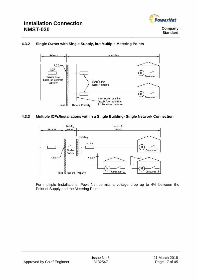
For Installation Owners with multiple metered Metering Points (see Dwg 4.3.2), a single supply charge is applied based on the overall Contract Supply Capacity. The following conditions apply:
3.7.4.1 All Metering Points must have a single Network Connection Point and must have an overall Contract Supply Capacity of no less than 15 kVA single phase or 30 kVA three phase.
3.7.4.2 The fuses at the ICP or low voltage side of the transformer (if applicable) will be sized according to the Contract Supply Capacity. Thus all Metering Points must be capable of operating together within that capacity.
3.7.4.3 Historically Mains have been allowed to extend up to three spans along the road on PowerNet poles. The line must be exclusively used by the Installation Owner and the latter will be responsible for the capital and renewal costs of the Mains along the road.
No new multiple Metering Points will be allowed using lines on PowerNet poles.
3.7.4.4 Line Charges are based upon the actual fusing arrangement at the ICP and/or MCB mounted on the Switchboard in accordance with the nondomestic premises schedule.
3.7.4.5 Installation Owners may choose to provide downstream fuses for each Metering Point if they wish to or alternatively downstream fuses may be required to comply with the Regulations, such as due to cable current rating. These fuses will be at the Installation Owner’s cost. The MCB could also be used for this purpose as well as determining the Line Charges.
3.7.4.6 It will not be possible for an Installation Owner with multiple Metering Points to have one of the Metering Points disconnected unless the Installation Owner is prepared to have the meters removed and the supply line or cable physically disconnected from the supply at the ICP. Unless the service fuses at the ICP are then downsized, or if appropriate an MCB fitted, the Line Charge will remain the same.
3.8 Installation/Disconnection
If an Installation is disconnected PowerNet reserves the right to remove all of its equipment including meters and transformers after reasonable endeavours to notify the last known Property Owner in writing.
If the Property Owner wishes to retain PowerNet equipment for possible future use they will be responsible for paying annual charges reflecting a return on the capital value of the equipment. The equipment will be disconnected from the Network and any remedial work prior to reconnection will also be at the Property/Installation Owner’s expense.
Installation Connection NMST-030
Company Standard
Approved by Chief Engineer
Issue No 3 3132547
21 March 2018 Page 15 of 45
4. OWNERSHIP BOUNDARIES AND RESPONSIBILITIES
4.1 General Conditions
In order to define maintenance responsibilities and allocate capital costs it is necessary to define the boundaries between fittings that are part of the Network and fittings that are part of the Installation.
A property boundary is defined as the legal boundary of the property occupied or owned by the Installation Owner. In a situation where the connection to an Installation is via cables in a right of way held in common with other Property Owners, the right of way is deemed to be part of the Installation Owner’s property.
All fittings on a property that are part of the Network will be maintained by PowerNet. Property Owners shall provide access to PowerNet or its agent to carry out this maintenance, testing and inspection and also provide reasonable mechanical protection to prevent damage to the equipment.
Maintenance of fittings that are part of the Installation is the responsibility of the Installation Owner.
4.1.1 Installation
The following are deemed part of the Installation, and the Installation Owner’s responsibility where they are within the property boundary relating to the Installation:
All LV lines and/or cables exclusively used by the Installation Owner.
HV lines and/or cables where there is a Specific Ownership Agreement for private
ownership.
4.1.2 Network
The following fittings, where located on private property, are deemed Network unless there is a Specific Ownership Agreement to the contrary:
Fittings used to convey electricity to other properties.
ICP Fuses.
High voltage substation equipment and/or transformer and associated earthing
(see 4.4).
Incoming HV switchgear when there is a HV supply.
HV lines and/or cables.

Installation Connection NMST-030
Company Standard
Approved by Chief Engineer
Issue No 3 3132547
21 March 2018 Page 16 of 45
4.2 Voltage Levels
PowerNet will maintain the voltage at the Point of Supply to within the statutory limits as prescribed in the Electricity Regulations.
Voltages and current will be measured as close as practical to the Point of Supply as follows:
(a) For LV connections the point where the Mains crosses the boundary, e.g. pillar box.
(b) For Installations with multiple Metering Points the single Point of Supply or ICP for all
Metering Points.
(c) For supply from a transformer on the Installation Owner’s premises, the LV terminals of
the transformer.
The apportioning of costs for rectifying voltages outside the limits depends on the cause of the problem.
If the voltage at the Point of Supply is outside the legal limits, PowerNet will be responsible for the solution to the level of the Contract Supply Capacity.
If the voltage at the Point of Supply is within the legal limits, the Installation Owners will be responsible if there is a problem on their premises.
PowerNet is not liable for any damage resulting from momentary fluctuations in the voltage.
In general PowerNet requires that the voltage drop between the Point of Supply and the meters does not exceed 2.5%. This limit is extended to 4% in some cases as shown in the following clauses. These requirements are consistent with requirements of the Electricity Regulations.
4.3 Low Voltage Installations
The Installation Owner is responsible for all costs associated with the Installation including the construction, maintenance and renewal.
4.3.1 Standard Single Installation Supply
Installation Connection NMST-030
Company Standard
Approved by Chief Engineer
Issue No 3 3132547
21 March 2018 Page 17 of 45
4.3.2 Single Owner with Single Supply, but Multiple Metering Points
4.3.3 Multiple ICPs/Installations within a Single Building- Single Network Connection
For multiple Installations, PowerNet permits a voltage drop up to 4% between the Point of Supply and the Metering Point.

Installation Connection NMST-030
Company Standard
Approved by Chief Engineer
Issue No 3 3132547
21 March 2018 Page 18 of 45
4.3.4 Multiple ICPs/Installations - Private Road
For 4.3.3 and 4.3.4 these fuses are provided by PowerNet and must be installed in such a manner that access is available to PowerNet authorised staff at all times. This is the ICP for the Installation.
4.4 High Voltage Installations
4.4.1 General
(a) The Installation Owner or Property Owner may be required to provide
foundations for some ground-mounted equipment.
(b) In all cases PowerNet permits a voltage drop of up to 4% between the Point of
Supply and the Metering Point.
4.4.2 LV Installation with Tee’d Transformer

Installation Connection NMST-030
Company Standard
Approved by Chief Engineer
Issue No 3 3132547
21 March 2018 Page 19 of 45
4.4.3 LV Installation with feed-through Substation
4.4.4 LV Installation with remote feed-through switchgear and Tee’d Transformer
In cases 4.4.2, 4.4.3 and 4.4.4 there may be no LV fuse, as described in clause 12.3.2. In these cases the HV fuse will be classed as the ICP fuse.
4.4.5 LV Installation with Tee’d Transformer and LV Interconnection
In cases 44.4.3, 4.4.4 and 4.4.5 PowerNet will require a legal easement to secure the Network components on the Property Owner’s property.

Installation Connection NMST-030
Company Standard
Approved by Chief Engineer
Issue No 3 3132547
21 March 2018 Page 20 of 45
4.4.6 HV Installation Connection
4.4.7 HV Installation with Dedicated HV feeders
4.4.8 HV Installation with Feed-through
For Dwgs 4.4.6, 4.4.7 and 4.4.8 a Specific Ownership Agreement will be established with the Installation Owner to confirm the point of demarcation in responsibility.

Installation Connection NMST-030
Company Standard
Approved by Chief Engineer
Issue No 3 3132547
21 March 2018 Page 21 of 45
5. APPLICATIONS AND APPROVALS
5.1 Applications for Network Connection
Applications for a connection to the Network shall be made on the PowerNet “Installation Connection Application” form. These forms are available at PowerNet’s office.
All details of Section 1 of the form must be completed and site/location plan provided to obtain approval for connection of an Installation to the Network.
5.2 Installation Modifications
Existing Installation Owners shall complete a PowerNet “Installation Connection Application” and obtain approval before proceeding with any of the following work.
(a) For domestic Installations, connection of appliances with a combined load in excess of
5kW.
(b) Connection of motors
For all Installations with Contract Supply Capacity up to 30kVA, installation of
electric motors greater than 1.5kW.
For Installations with Contract Supply Capacity over 30kVA, installation of electric
motors greater than 5% of the Contract Supply Capacity.
Details of motors are to be provided on the Motor Installation Form shown in
Appendix 3. This form must be accompanied by an Installation Connection
Application form showing the Contract Supply Capacity required, (either
confirming the existing capacity or requesting a change).
(c) Connection of Power Factor correction equipment.
(d) Installing an appliance that may affect the quality of supply to other Installations by the
introduction of harmonics or by causing voltage fluctuations, e.g. welders, etc.
(e) Replacing, reconfiguring or altering all or part of the Mains between the Installation
Owner’s boundary and the Metering Point.
(f) Installation of capacitors that result in the total capacitive load of an Installation exceeding
2% of the Contract Supply Capacity.
(g) Requesting a change in the Contract Supply Capacity.
(h) Installing any generation equipment.
(i) Relocation of the meter board.
Installation Connection NMST-030
Company Standard
Approved by Chief Engineer
Issue No 3 3132547
21 March 2018 Page 22 of 45
Note: Where a builders temporary is set up on the end of a new permanent Mains cable, in what will become its final location once the new building is completed, fitting the board to the building is not considered relocation and no application is required. However, the electrician is responsible for having the metering recertified if seals are broken to connect the new internal circuits.
(j) Adding a new separately metered building under an existing supply point (ICP).
(k) Reconfiguring supplies for Installations previously on separate supply points (ICPs) to be
fed from a single ICP.
5.3 Approval to Connect
The following conditions shall be met before a connection will be permitted:
(a) The Installation Owner has entered into an agreement to take supply of electricity from an
Electricity Retailer.
(b) The Installation (including any Mains) has a certified Electrical Certificate of Compliance
issued in accordance with the Electricity Regulations.
(c) The Installation Owner has agreed to pay the Connection Fee, Capital Contribution if
applicable and any other costs required to provide a supply. If applicable, the Capacity
Guarantee Agreement must also be signed off.
(d) The metering has been installed by a person authorised under the EGR.
5.4 Customer Connection Service Standards
Appendix 4 details the current service standards provided by PowerNet.
Installation Connection NMST-030
Company Standard
Approved by Chief Engineer
Issue No 3 3132547
21 March 2018 Page 23 of 45
6. COSTS FOR A NEW NETWORK CONNECTION
6.1 Cost Responsibilities
(a) All costs including construction associated with the Installation are the responsibility of the
Installation Owner. The demarcation points between the Installation fittings and Network
fittings are defined in clause 4.
(b) In order to establish a Network Connection Point, PowerNet may need to carry out
additions or alterations to its network. Installation Owners may be required to enter into
a Capacity Guarantee Agreement and/or make a Capital Contribution towards the cost of
this work in accordance with the current PowerNet capital investment conditions.
(c) All new connections will incur a Connection Fee payable by the Installation Owner when
the supply is connected. This fee covers the costs of administration for processing the
application, including raising the ICP and notifying and/or liaising with the
Electricity Retailer.
(d) If the supply is initially taken as a temporary arrangement (builders’ temporary supply) the
costs of converting it to the final permanent arrangement will be the responsibility of the
Installation Owner.
(e) When there is a choice of connection method the method resulting in the overall lowest
Network capital investment for PowerNet shall be used subject to (a) and (b) above.
(f) If an Installation Owner requires a connection method other than the one resulting in the
lowest cost to PowerNet, the Installation Owner shall make an additional
Capital Contribution equal to the difference in cost between the selected method and the
lowest cost method.
6.2 Enhanced Supply
When an Installation Owner requires a supply with enhanced electrical characteristics or enhanced reliability beyond that which would normally be provided, then the Installation Owner shall meet the additional costs incurred by PowerNet in providing facilities to satisfy those requirements.
6.3 Temporary Connection
Where a supply is required for a short period of time and then will be removed completely, all costs associated with the provision and removal of a temporary connection shall be met by the Installation Owner.

Installation Connection NMST-030
Company Standard
Approved by Chief Engineer
Issue No 3 3132547
21 March 2018 Page 24 of 45
7. INSTALLATION LOADS
7.1 Power Factor
The Power Factor of an Installation measured at the Metering Point shall not be less than 0.95 lagging. All Installations with a Contract Supply Capacity 100kVA and above shall be metered using kVA Demand Metering.
In general, to ensure compliance all motors rated above 2.0kW should have power factor correction capacitors installed. See clause 7.5 for conditions relating to installation of capacitors.
7.2 Voltage Fluctuations
Electric appliances which are part of one Installation shall not cause voltage fluctuations at the point of common coupling with other Installations in excess of the threshold of irritability as determined in the appropriate New Zealand Standards or other legislation in force at the time.
7.3 Motor Starting
The motor starting limitations of this standard are those recommended in the NZ Electrical Supply Engineers Association report on Motor Starting Currents for AC motors and in all cases must comply with clause 7.2.
Running motors with fluctuating loads shall also comply with clause 7.2 (available from the Electricity Engineers Association).
7.3.1 Exempt Motor Sizes
AC motors up to the sizes shown below are normally not subject to starting current limits and may be started direct on line.
Residential areas Single phase 1.5kW
Single phase 2.0kW In commercial and industrial areas
Three phase 4.0kW In residential areas
Commercial and industrial areas
Three phase 7.5kW

Installation Connection NMST-030
Company Standard
Approved by Chief Engineer
Issue No 3 3132547
21 March 2018 Page 25 of 45
7.3.2 Non-Exempt Motors
All motors larger than shown in clause 7.3.1 shall be approved by PowerNet prior to connection. The criteria used for approval is that the relative voltage changes on motor start-up shall not exceed the values shown below:
Maximum Relative Voltage
Change
Frequency of Starting At PCC At Zone Substation
11kV or 6.6kV Bus
In excess of 10 starts per hour 1% 0.5%
In excess of 3 starts per day but
not more than 10 starts per hour 3% 1.0%
Not more than 3 starts per day including not more than 1 start between the hours of 5 pm and 11 pm on any day
6% 1.5%
Emergency equipment started
infrequently (e.g. fire pumps) 12% 2.0%
7.3.3 Multiple Motor Installations
If several motors on an Installation start automatically when supply is restored after an interruption, then unless delayed or sequenced starting is installed to the satisfaction of PowerNet, the relative voltage change will be assessed on the basis of all motors on automatic control starting simultaneously.
7.4 Harmonic Disturbances
Harmonic voltages and currents introduced into the Network by appliances in an Installation shall not exceed the levels specified in NZECP36.
PowerNet operates ripple control systems with frequencies of 217 Hz (EIL and TPCL) and 317 Hz and 492 Hz (OJV). In addition to the requirements of NZECP36 appliances shall not cause voltages at the above frequencies in excess of 0.7% of the main voltage at the point of common coupling.
Installation Connection NMST-030
Company Standard
Approved by Chief Engineer
Issue No 3 3132547
21 March 2018 Page 26 of 45
7.5 Capacitors
Installation Owners are permitted to install unfiltered capacitor kVAr capacity up to 2% of connection kVA capacity.
Note:
For three phase connections the maximum kVAr per phase is 1/3 the total kVAr allowed. For capacitor loads exceeding the limit above, specific permission to connect shall be obtained from PowerNet which will determine if blocking filters are required. The Installation Owner is responsible for the provision and correct operation of the filters.
Installation Owners installing fluorescent lighting loads are advised to use fittings with lead-lag ballasts which will provide power factor correction without the risk of ripple signal absorption. Electronic fluorescent lighting ballasts do not require capacitors for power factor correction, hence they will not absorb ripple control signals.
8. MAINS
8.1 General Requirements
All Mains shall be rated and installed in accordance with Electricity Regulations and PowerNet will require an inspection by a Registered Inspector and Certificate of Compliance prior to livening.
8.2 Installation Livening
Mains can be installed by any person competent and qualified as defined by the Electricity Regulations.
New or replacement Mains shall only be connected to the ICP (service) fuse by a person authorised by PowerNet.
Fusing will be in accordance with clause 3.1.
No connection to the Network will be livened without the documented approval of PowerNet through the PowerNet “Installation Connection Application” form with all sections completed. There are also strict PowerNet authorisation procedures for connecting Installations to the Network.
Note: Evidence of appropriate Power Factor correction equipment will be required if applicable.

Installation Connection NMST-030
Company Standard
Approved by Chief Engineer
Issue No 3 3132547
21 March 2018 Page 27 of 45
8.3 Aerial Mains
All newly constructed or altered lines or line segments must conform to the requirements of this clause, and also those shown in Appendix 5, before connection to the Network will be allowed.
8.3.1 General Conditions for all Aerial Mains
(a) For new or altered connections the Installation Owner is required to provide
dimensions of the location of any pole to carry PowerNet equipment
(e.g. transformer, HV fuses, LV service fuses, etc.) to an accuracy of +/- 5m
measured from a property boundary or existing PowerNet pole.
These details must be shown on the sketch accompanying the application. This position will be recorded in the PowerNet Network mapping system. For identification purposes a PowerNet pole number will be allocated and a label must be fixed to the pole.
(b) The line must be self-supporting, i.e. full conductor tension cannot be taken on
the Network pole. The total maximum take-off force perpendicular to the Network
line allowed on the Network pole is 1000 Newtons. The maximum length of the
first span from the Network pole is 60m.
(c) If the line is no more than three spans, each span is less than 60 metres and the
maximum total take off force on the pole does not exceed 1000 Newtons it may
not be necessary to install a stay and “slack span” at the take-off end.
(d) Strain poles shall not be pre-stressed concrete, or ‘light’ construction mass
reinforced pole.
(e) Good engineering practice must be followed. E.g. not using stay eye-bolts to
secure other equipment such as stay straps or crossarms, and fitting pole caps
to wooden poles.
(f) Must comply with Electricity Regulations with respect to electrical safety, i.e. pole
strength, conductor clearances, sound connections and free from vegetation
hazards.
(g) Termination and angle poles must be adequately stayed with stay wires
protected by cattle guards in vulnerable positions, such as open paddocks.
(h) Special consideration should be given to pole positions so they are not exposed
to being hit by vehicles or plant.

Installation Connection NMST-030
Company Standard
Approved by Chief Engineer
Issue No 3 3132547
21 March 2018 Page 28 of 45
8.3.2 Special Conditions for LV Mains
(a) Aluminium conductor may only be used with approved bimetallic connectors at
each termination or joint using different metals.
(b) Aerial LV Mains shall generally be copper conductor with a minimum size of
16mm2 or aluminium conductor with a minimum size of 25mm2. The Installation
Owner is responsible for providing conductor supports and terminations on his
premises. The Mains shall be installed in accordance with ECP28 and ECP34
and satisfy the requirements of the Electricity Regulations.
(c) It is recommended where possible, neutral screened cable or aerial bundled
cable be used for aerial LV Mains due to the enhanced safety this provides.
8.3.3 Special Conditions for Reconstructed Mains
When the respective portion of the line is being worked on, as described below, the Installation Owner must bring that portion of the line up to the appropriate requirements of this standard as follows:
(a) First span to be ‘slack span’
(i) On replacement or relocation of the first pole from the Network
connection pole.
(ii) When rewiring with a larger size of wire than the original line.
(iii) When upgrading the line by the addition of extra wires, e.g. conversion
from single to three phase.
(iv) During any other work that would increase the mechanical loading on
the Network pole the line is connected to, e.g. restraining the wire.
At any other time PowerNet may request that a slack span be installed in conjunction with an Installation Owner’s own work on a line. In this case PowerNet may pay (only) the incremental cost for the slack span. Decisions on the application of this will be made on a case by case basis.
(b) Strain pole type
(i) When replacing a strain pole.
(ii) When relocating a strain pole to a position that would make it vulnerable
to being hit by a vehicle or farm machinery, e.g. into an open paddock.
Installation Connection NMST-030
Company Standard
Approved by Chief Engineer
Issue No 3 3132547
21 March 2018 Page 29 of 45
(c) General engineering and construction methods, e.g. lock nuts and eye bolts
(i) On replacement or rebuilding of each individual pole.
8.4 Underground LV Mains in Underground Reticulated Areas
LV Mains in areas with underground LV reticulation will be connected to the Network via an LV pillar box of appropriate size located on the property boundary.
8.4.1 Pillar Boxes
Pillar boxes are special purpose junction boxes that accommodate LV service fuses and provide facilities for connection to the LV underground distribution cables.
Pillar boxes are normally located on the street side of the Installation Owner’s property boundary. In residential areas, pillar boxes are generally placed on the street frontage at the junction of two property boundaries allowing the box to serve the two properties.
8.4.2 Connection of Mains to Pillar Boxes
The connection of LV Mains into pillar boxes will be PowerNet’s responsibility. Installation Owners shall ensure the Mains cable is installed to the pillar box position with sufficient length to facilitate termination. Copper and aluminium cables can be used for underground Mains, but aluminium cables will require to be terminated with copper tails via AL/CU transition joints for connection into fuse bases. The copper/aluminium transition joint is the responsibility of the Installation Owner. The maximum cable size for a 60 amp fuse base is 35mm2 copper and for a 100 amp fuse base is 50mm2 copper. If the Mains exceed these sizes reduced size tails are required to be fitted by the contractor.
For larger commercial and industrial Installations, PowerNet will discuss terminations on an individual basis.
8.5 LV Underground Mains in an Overhead Area
8.5.1 Pole Top Supply
In areas where the existing LV Network is overhead Installation Owners can make connection via an underground cable running direct from pole top to meter box or main switchboard by having the Mains buried to the base of a nearby pole, attached to the pole and terminated on to a pole top fuse subject to the following conditions:
(a) The service cable shall preferably have a copper neutral screen with stranded
copper or aluminium conductors.

Installation Connection NMST-030
Company Standard
Approved by Chief Engineer
Issue No 3 3132547
21 March 2018 Page 30 of 45
For connections up to 60 amps the conductors to be terminated in the PowerNet service fuse must be stranded copper and no greater than 35mm2.
For connection capacities greater than 60 amps and up to 400 amps the conductors to be terminated must be stranded copper and be no larger than 185mm2.
(b) The cable in the road reserve will be installed by PowerNet. For new connections
the cost of this is included with any other costs for the supply in the calculation of
possible charges. For alterations to existing supply, e.g. conversion from aerial
to underground cable, these costs will be the Installation Owner’s responsibility.
(c) The cable shall cross the Installation Owner’s property boundary at a location
determined by PowerNet that results in the minimum trenching in the road
reserve.
(d) The Installation Owner shall provide adequate cable to enable connection at the
top of the pole.
8.5.2 Pillar Box Supply
In some special circumstances as will be determined by PowerNet, a pillar box will be installed on the boundary. In this case PowerNet will install the connection from the pole top to the box. The connection of the Installation Owner’s Mains into the pillar box will be as per clause 8.4.
9. TRANSFORMERS OR SUBSTATIONS ON INSTALLATION
OWNERS’ PREMISES
9.1 General Requirements
The maximum single transformer capacity available is generally three phase 1000 kVA. Installations requiring capacities in excess of 1000 kVA will normally require more than one transformer. The size of transformer installed will be at the discretion of PowerNet.
When an Installation is supplied by more than one transformer, the LV connections from the transformers shall not be paralleled unless inter-tripping facilities between the HV and LV Circuit Breakers are installed to prevent back-feed from the LV bus to the HV transformer winding.
When it is necessary to install a substation on an Installation Owner’s premises, the Owner shall make available on his premises suitable space to accommodate the transformer, HV cable or lines and associated switchgear.
HV circuits across the Installation Owner’s property can be either underground cable or overhead line. A site plan showing the proposed substation location and route for lines or cables is required.
Installation Connection NMST-030
Company Standard
Approved by Chief Engineer
Issue No 3 3132547
21 March 2018 Page 31 of 45
The Installation Owner shall grant an easement in PowerNet’s favour for fittings that are associated with the conveyance of electricity if the substation is to also supply other Installations and PowerNet will arrange and meet the surveying and legal costs associated with obtaining the easement. The easements will give PowerNet access rights to equipment associated with the supply of electricity to other Installations for operational and maintenance purposes.
The connection configuration appropriate for each Installation will be decided by PowerNet in consultation with the Installation Owner. The following factors are considered when choosing the most appropriate connection method:
(a) Location of HV distribution lines and cables.
(b) Location of main switchboard.
(c) Access to substation (24 hour access required).
(d) Supply security requirements.
(e) Contract Supply Capacity.
(f) Requirement for LV interconnection for back-up or supply to other Installations.
(g) Cost
(h) Provision of adequate protection to prevent accidental contact with live terminals including
high voltage secondary protection.
9.2 Space Requirements
The space requirements for a substation on an Installation Owner’s property will depend upon the substation type. In all cases allowance should be made for earth conductors and rods.
9.2.1 Pole Substations
For capacities up to 100kVA the transformer and associated fuses may be accommodated on a single pole. For capacities greater than 100kVA and up to 500kVA a two pole structure is required although in most instances PowerNet’s policy is to use a ground mounted substation.
The siting of the substation will depend on the location of buildings and the routing of HV lines. Electrical clearances defined in NZECP34 shall be maintained.

Installation Connection NMST-030
Company Standard
Approved by Chief Engineer
Issue No 3 3132547
21 March 2018 Page 32 of 45
9.2.2 Kiosk Substation
A kiosk substation is an outdoor substation with switchgear and transformer accommodated on a concrete base and contained within an integral weather-proof enclosure. These substations can accommodate a single transformer with a capacity up to 1000kVA.
9.2.3 Indoor Substations
Indoor substations are used when the Installation Owner is unable to provide a suitable outdoor site or for technical or economic reasons. The entire substation can be inside or just the HV and LV switchgear. The provision of the space for the substation shall be in accordance with NZS6108 “Accommodation for Electrical Supply Substations in Customers Buildings”.
9.2.4 Outdoor Ground Mounted Substations
These substations consist of a pad-mounted transformer and in many cases ground mounted switchgear will be required. This switchgear may be remote from the transformer. Both the transformer and switchgear can be provided with a weather-proof cover or be non-enclosed.
10. INSTALLATION WITH GENERATION
Where an Installation includes generating equipment for emergency power supply purposes, suitable interlocks shall be provided to prevent the generator being connected to the Network.
An Installation Owner wishing to install generation intended to operate in parallel with the Network should consult with PowerNet to ascertain the requirements applicable to the Installation. The requirements will generally be in accordance with the “Electricity Supply Engineers Association Guide for the Connection of Generating Plant May 1992”.

Installation Connection NMST-030
Company Standard
Approved by Chief Engineer
Issue No 3 3132547
21 March 2018 Page 33 of 45
11. FAULT LEVEL CONSIDERATIONS
11.1 General
The short circuit rating of Installation equipment at the Point of Supply should be not less than the design fault level of the Network to which it is connected. The choice of equipment for LV connection may take into account attenuation in the Mains.
The PowerNet 11kV Network is designed for a maximum short circuit level of 250MVA, i.e. 13kA at 11kV. 11kV Installations should be designed for a 250MVA prospective short circuit level.
For Installations supplied from the LV Network in residential areas, the prospective short circuit level at the main switchboard will typically be less than 6000 amps.
For Installations supplied from a dedicated transformer, the maximum prospective short circuit levels at the LV terminals of the transformer are as shown below.
Transformer Size
(kVA)
Maximum Prospective
Short
Circuit Current
(amps)
Up to 50 2,000
Up to 100 4,000
Up to 200 6,500
Up to 300 9,500
Up to 500 15,000
Up to 750 22,000
Up to 1,000 28,000
Note: If an Installation requires a single LV busbar supply greater than 1,000 kVA, then parallel transformers will be required which will increase the maximum prospective short circuit current.
11.2 Contribution to Fault Level from within the Installation
In the design of the Network, PowerNet may need to take into account the contribution to fault level by the Installation equipment such as large motor loads.
In order to permit these assessments to be carried out, information should be exchanged on prospective fault-power in-feed at the Network Connection Point.

Installation Connection NMST-030
Company Standard
Approved by Chief Engineer
Issue No 3 3132547
21 March 2018 Page 34 of 45
12. PROTECTION
12.1 General
The Electricity Regulations require that every person supplying line function services shall provide a service protective device of appropriate rating to provide protection against short circuits or earth faults on Mains and also prevent such Mains faults from affecting the supply to other consumers.
NZECP28 (2.1.3) requires that the maximum current in a cable must not exceed the current rating of the conductor.
12.2 Protection of LV Mains Connected to LV Distribution Network
Mains connected to the LV distribution system will be protected by HRC fuses in boundary pillar boxes or by pole mounted fuses. These service fuses will provide short circuit protection for the Mains and main switchboard. Installation Owners shall ensure the current rating of their Mains and main switchboard is greater or equal to the service fuse rating or adequate overload protection is provided.
In the case of some premises within the Invercargill CBD the Mains up to the switchboard will have fault protection provided by the distribution cable fuse (up to 400 amp) and overload protection will be provided by the Installation Owner’s main switch. PowerNet will provide fuses for this switch which is the ICP for the Installation.
12.3 LV Connections from a Substation on an Installation Owner’s Property
12.3.1 Transformers up to 300kVA
For transformer capacities up to 300kVA Mains protection will be provided by LV HRC fuses or a Circuit Breaker mounted adjacent to the transformer.
12.3.2 Transformers greater than 300kVA without an LV Interconnection
If a transformer capacity is greater than or equal to 300kVA and it is dedicated to supply one Installation with no LV interconnection, the LV Mains may be connected directly to the transformer LV terminals.
To ensure the transformer HV fuses can detect phase to earth faults at the main switchboard, the Mains shall be sized to carry the rated current of the transformer and may only be longer than 20 metres with special approval by PowerNet.
Transformer HV fuses provide short circuit protection only for LV Mains. Installation Owners are required to provide overload protection that will operate their incoming circuit breaker.

Installation Connection NMST-030
Company Standard
Approved by Chief Engineer
Issue No 3 3132547
21 March 2018 Page 35 of 45
12.3.3 LV Supply from a Substation with an LV Interconnection
When an Installation is supplied from a transformer that is primarily for supply of that Installation but also has an interconnection with the LV Network, the Mains will be protected by HRC fuses for connection capacities up to 400 amps and by a Circuit Breaker for connection capacities between 400 and 800 amps.
12.4 Protection of HV Connections
The HV Mains for Installations supplied overhead are generally protected by the feeder protection at the Network Zone Substation. If Installation protection is provided it must be designed to discriminate with the Network protection such that faults within the Installation beyond the incoming Circuit Breaker or fuse switch will not normally result in tripping of a Zone Substation feeder Circuit Breaker.
12.5 Unbalanced Voltage
It is possible for one or two fuses of a three phase set protecting Mains or a transformer to operate, resulting in an unbalanced or reduce voltage to occur at an Installation. PowerNet will not accept responsibility for any damage to Installation equipment caused by this condition. If Installation Owners have equipment vulnerable to damage by unbalanced or reduced voltage they are advised to install their own protection that will automatically disconnect the appropriate equipment.
12.6 Ripple Receivers
Ripple Receivers must be protected by a HRC fuse no greater than 80 amps. On many commercial and industrial switchboards this will mean the installation of an additional fuse. Contactors and the fuses protecting the contactors are part of the Installation and shall be supplied by the Installation Owner.
13. METERING
13.1 General Metering Requirements
Installation Owners shall provide appropriate space within their premises to accommodate metering equipment and load control relays required by PowerNet and the Energy Retailer.
13.2 Metering Requirements for All Installations
If outdoor metering is chosen the meter boxes shall be mounted in a location readily accessible by meter readers. The top of the box shall be no higher than 2.0 meters above ground level and the bottom of the box no lower than 1.0 metres above ground level.
The meter board or box shall be installed to comply with all current industry regulations or requirements.
Installation Connection NMST-030
Company Standard
Approved by Chief Engineer
Issue No 3 3132547
21 March 2018 Page 36 of 45
The Installation Owner is responsible for the installation of the Mains into the box and the controlled and uncontrolled load sub-circuits leaving the meter box. These circuits shall enter the box preferably at the top or if appropriate at the bottom with sufficient length to be terminated on to meters or relays. The Installation electrician shall terminate the service main neutral with a suitable solder or compression joint which also accommodates the tails necessary to provide a neutral connection for the meters and relays. Alternatively the main neutral can be looped through the main meter before connection to the neutral stud.
For premises with a connected capacity of 100 amps or less a main switch is not permitted between the supply and the meters and ripple receiver. Directly connected meters will be used. In many cases the neutral may be looped through the meter terminals.
If a main switch is installed in an outdoor meter box or on a combined meter/switchboard a warning label is to be attached informing people that the meters and ripple receiver are not controlled by the switch.
PowerNet’s Load Control Devices are able to switch directly loads up to 40 amps single phase. Where the Installation controlled load exceeds this the Installation Owner will be responsible for the supply and installation of a suitable auxiliary control device. The installation and connection of the meters and Load Control Devices is the responsibility of the Electricity Retailers chosen Metering Equipment Provider. Where the Network has installed a smart meter at the premises, this meter must remain in place connected to the full installation load. If the retailer wishes to use an alternative Metering Equipment Provider for their revenue metering, then the retailers meter must be installed in series with the network meter. The Network meter may also provide any load control switching for controlled tariffs.
If an Installation Owner requires extra or enhanced metering the Installation Owner shall meet the extra costs.
If CT meters are required for Installations with less than 100 amps, this should be specified by the Installation electrician on the PowerNet Installation Connection Application form.
If Installation Owners carry out work on their own premises which will involve breaking of meter seals, e.g. the relocation of the meters, arrangements must be made with the electricity retailer responsible for the site.
13.3 Metering Requirements for Installations with Contract Supply Capacity of 100kVA
and Greater
Supplies with a Contract Supply Capacity of 100kVA (160A) and greater require current transformers (CT’s) to measure the load current. There must be a single set of three single phase CT’s, and these must measure the total load of the installation.
For Contract Supply Capacities greater than 100kVA the metering must be kVA Demand Metering or TOU Metering. The actual metering will be arranged by the Electricity Retailer.

Installation Connection NMST-030
Company Standard
Approved by Chief Engineer
Issue No 3 3132547
21 March 2018 Page 37 of 45
Provision shall be made in the main switchboard to accommodate the metering current transformers and provide a metering potential supply. A suitable cabinet shall also be provided to accommodate the required meters and load control relays.
The Installation Owner is responsible for providing or arranging and installing the following equipment, to meet the EGR and the Electricity Retailer’s (or their metering agent’s) requirements:
CT’s – Certified under the EGR
CT Shorting/Test Block
Primary Potential Fuses at the main potential connection
Secondary Potential Fuses in metering compartment
Suitably rated fuse links must be chosen for the potential fuses to ensure discrimination, such that metering compartment fuses would operate first in the event of a fault inside the compartment, or metering.

Installation Connection NMST-030
Company Standard
Approved by Chief Engineer
Issue No 3 3132547
21 March 2018 Page 38 of 45
APPENDIX 1 - CAPACITY GUARANTEE AGREEMENT
Introduction
Any appliance which is part of an electrical installation requires the electricity network to have sufficient investment in lines etc. to be able to convey electricity to that appliance in accordance with all statutory legislation and sound engineering practice.
The investment required in and hence the capacity of the Network has to satisfy the Contract Supply Capacity of the installation.
For new Loads or Load increases in excess of 100kVA, the line charges in general relating to network investment recover the costs over the life of the assets which on average is 40 years.
The Capacity Guarantee Agreement is designed to reduce the risk to PowerNet of stranded or underutilised capital assets and negate the need for large “headworks” or capital contribution often required by other line companies.
The Capacity Guarantee Agreement enables PowerNet to recover the balance of its investment if the Installation Owner wishes to reduce the Contract Supply Capacity before 10 years has elapsed.
Application of Capacity Guarantee Agreement
A Capacity Guarantee Agreement will be required in the following situations:
A new installation connection requiring a Contract Supply Capacity of 138kVA or greater.
An existing installation increasing Contract Supply Capacity by greater than 100kVA.
PowerNet will carry the risk on smaller installations.
The Capacity Guarantee Agreement will be applied in addition to and not instead of a Capital Contribution if the distribution system has to be significantly extended beyond the economic value and there is an unacceptable risk to PowerNet of stranded assets.
The term of the Capacity Guarantee Agreement will be 10 years.
As an alternative to the Capacity Guarantee Agreement the consumer may opt to pay an annual payment equal to between 10% and 20% of the Capacity Guarantee Agreement for the 10 year period. The actual percentage would depend on the estimated or perceived risk of underutilised or stranded assets, i.e. a type of ‘beta’ factor. The first annual payment would be payable in advance and prior to the commencement of any work.

Installation Connection NMST-030
Company Standard
Approved by Chief Engineer
Issue No 3 3132547
21 March 2018 Page 39 of 45
A consumer can transfer from paying the annual payment to take out a Capacity Guarantee Agreement at any time during the 10 years, but a consumer cannot transfer from a Capacity Guarantee Agreement to the annual payment option.
There is also an option for a consumer to take out a shortened term Capacity Guarantee
Agreement and an annual payment for that period which would cover the difference in the
Capacity Guarantee for each year.
Embedded Networks
Embedded Network owners are required to take supply capacity in steps equivalent to the PowerNet standard transformer sizing.
Two options are available for embedded networks. The first is based on a Capacity Guarantee Agreement for each new capacity supply level, with (distributors charges and Transpower Connection charges) based on the total capacity and the variable Transpower Interconnection Charge based on actual coincident peaks. The second option is to pay a fee of three times the distributor’s portion of the incremental step capacity annual line charge and pay line charges during the period up to the time the capacity reaches the step value based on actual capacity connected.
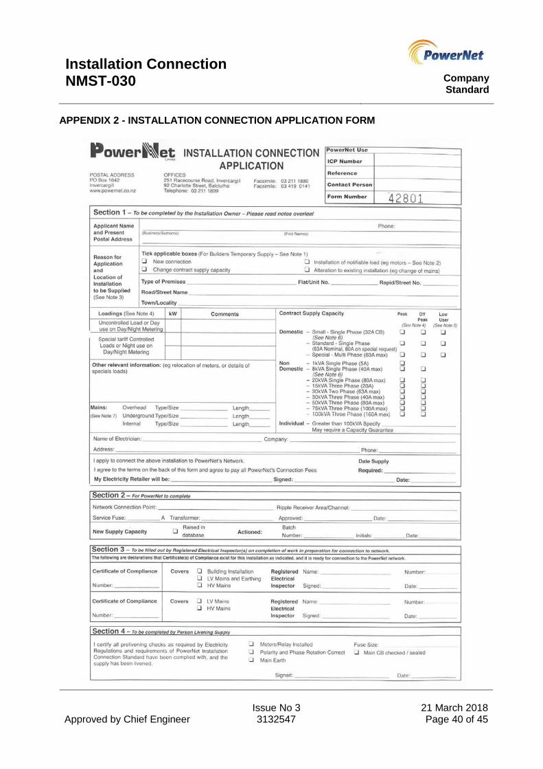
Installation Connection NMST-030
Company Standard
Approved by Chief Engineer
Issue No 3 3132547
21 March 2018 Page 40 of 45
APPENDIX 2 - INSTALLATION CONNECTION APPLICATION FORM

Installation Connection NMST-030
Company Standard
Approved by Chief Engineer
Issue No 3 3132547
21 March 2018 Page 41 of 45

Installation Connection NMST-030
Company Standard
Approved by Chief Engineer
Issue No 3 3132547
21 March 2018 Page 42 of 45
APPENDIX 3 - MOTOR APPLICATION FORM
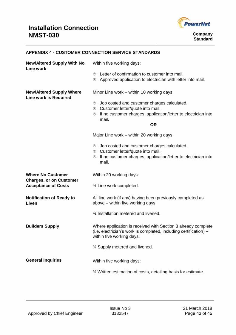
Installation Connection NMST-030
Company Standard
Approved by Chief Engineer
Issue No 3 3132547
21 March 2018 Page 43 of 45
APPENDIX 4 - CUSTOMER CONNECTION SERVICE STANDARDS
New/Altered Supply With No
Line work
Within five working days:
Letter of confirmation to customer into mail.
Approved application to electrician with letter into mail.
New/Altered Supply Where
Line work is Required
Minor Line work – within 10 working days:
Job costed and customer charges calculated.
Customer letter/quote into mail.
If no customer charges, application/letter to electrician into
mail.
OR
Major Line work – within 20 working days:
Job costed and customer charges calculated.
Customer letter/quote into mail.
If no customer charges, application/letter to electrician into
mail.
Where No Customer
Charges, or on Customer
Acceptance of Costs
Within 20 working days:
¾ Line work completed.
Notification of Ready to
Liven
All line work (if any) having been previously completed as above – within five working days:
¾ Installation metered and livened.
Builders Supply Where application is received with Section 3 already complete (i.e. electrician’s work is completed, including certification) – within five working days:
¾ Supply metered and livened.
General Inquiries Within five working days:
¾ Written estimation of costs, detailing basis for estimate.
Installation Connection NMST-030
Company Standard
Approved by Chief Engineer
Issue No 3 3132547
21 March 2018 Page 44 of 45
Urgency While the above are nominal maximum timeframes, genuine
urgency will be accommodated where possible. This must not
be to the extent that it causes excessive delays to other
programmed work.
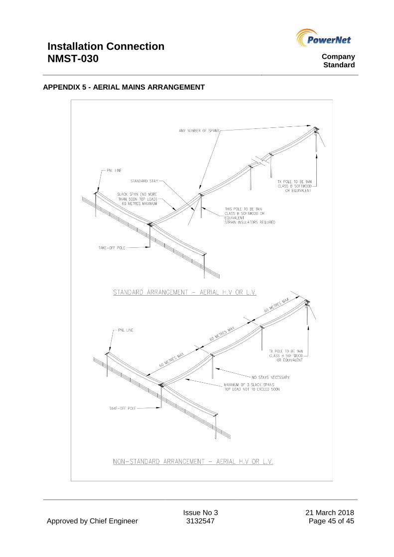
Installation Connection NMST-030
Company Standard
Approved by Chief Engineer
Issue No 3 3132547
21 March 2018 Page 45 of 45
APPENDIX 5 - AERIAL MAINS ARRANGEMENT


![[030] 2009](https://img.dokumen.tips/doc/110x75/568bd8e71a28ab2034a514ec/030-2009.jpg)


