Embed Size (px)
Citation preview
CompanionService Guide
This Service Guide contains:Troubleshooting
Replacement Instructions

WWW.GOLDENTECH.COM [email protected] PAGE - 2
Contact Information
Golden Technologies401 Bridge StreetOld Forge, PA 18518Toll-free: 800-624-6374Fax: 800-628-5165Lift Chair/Bed Tech: x502Mobility Tech: x501VA Tech: x505Email: [email protected]
WWW.GOLDENTECH.COM [email protected] PAGE - 3
Table of ContentsABOUT THE COMPANION SERVICE GUIDE .................................................................................................... 4Companion Components ............................................................................................................................................................... 4SCENARIO 1: TURN THE KEY TO THE ON POSITION AND NO POWER ................................................ 13SCENARIO 2: BATTERIES WON'T CHARGE .................................................................................................. 14FLASH CODES ........................................................................................................................................................ 15FLASH CODE #1 – Batteries Low (Scooter may drive slowly.) ................................................................................................ 15FLASH CODE #2 – Batteries Low (Scooter will not operate.) .................................................................................................. 15FLASH CODE #3 - High Battery Voltage ................................................................................................................................... 15FLASH CODE #4 - Current Limit Timeout ................................................................................................................................ 15FLASH CODE #5 - Brake Fault .................................................................................................................................................. 16FLASH CODE #6 - Paddle Fault (out of neutral) ....................................................................................................................... 17FLASH CODE #7 - Paddle Fault/Speed Control Fault (voltage error) ....................................................................................... 17FLASH CODE #8 - Motor Voltage Fault (Open) ........................................................................................................................ 18FLASH CODE #9 - Controller Fault ........................................................................................................................................... 19COMPANION REPLACEMENT INSTRUCTIONS ............................................................................................ 20Motor/Brake Assembly Replacement .......................................................................................................................................... 20Motor Brush Replacement ........................................................................................................................................................... 21Drivewheel Replacement ............................................................................................................................................................. 21Battery Replacement ................................................................................................................................................................... 21Throttle Pot Replacement ............................................................................................................................................................ 22Key Switch Replacement ............................................................................................................................................................ 22Control Panel Fuse Replacement ................................................................................................................................................. 22Circuit Breaker Replacement ...................................................................................................................................................... 23Controller Replacement ............................................................................................................................................................... 23Charger Harness Fuse Replacement ............................................................................................................................................ 24Main Harness Replacement (340) ............................................................................................................................................... 24APPENDIX A - HOW TO USE A VOLTMETER.................................................................................................. 26APPENDIX B - HOW TO USE AN OHM METER .............................................................................................. 27APPENDIX C - WIRING DIAGRAM .................................................................................................................... 28
WWW.GOLDENTECH.COM [email protected] PAGE - 4
About the Companion Service GuideThis service guide provides you with the information necessary to troubleshoot the Golden Technologies Com-
panion (GC-240, GC-340, and GC-440) equipped with the R-Series Controller. The troubleshooting scenarios in thismanual consist of procedures that enable you to systematically trace and correct faults in the system. Appendices A andB include instructions on how to use a multimeter to measure voltage and continuity. Appendix C includes a copy offigure 13 that may be printed separately.
Before troubleshooting, check the following:• Make sure that the circuit breaker is reset.• Visually check terminals for corrosion. Check wires for missing insulation.• Make sure that the batteries are fully charged and are in good working order. When possible, keep sets of
known good batteries of various ratings in your shop at all times. The Companion uses two (2) 35AH (U1)batteries. Problems that surface during troubleshooting are often due to the fact that the batteries are not fullycharged or cannot hold their charge.
• Make sure that the electrical connections are secure. Unplug the connectors and make sure all of the pinsare seated properly. Push the pins back into the connector housing if necessary. Make sure that the batteryterminals are tight.
NOTE: If you get to a point during troubleshooting where you cannot continue, call tech support at800-624-6374.
COMPANION COMPONENTSThe Companion is a battery-operated scooter controlled by a Dynamics R-Series controller. The R-Series
controller monitors the system and displays flash codes when it detects a fault in the system. The Companion wasdesigned to operate within a range of between 18 – 24 volts (V) of direct current (DC).
The Companion control system is made up of the following components.
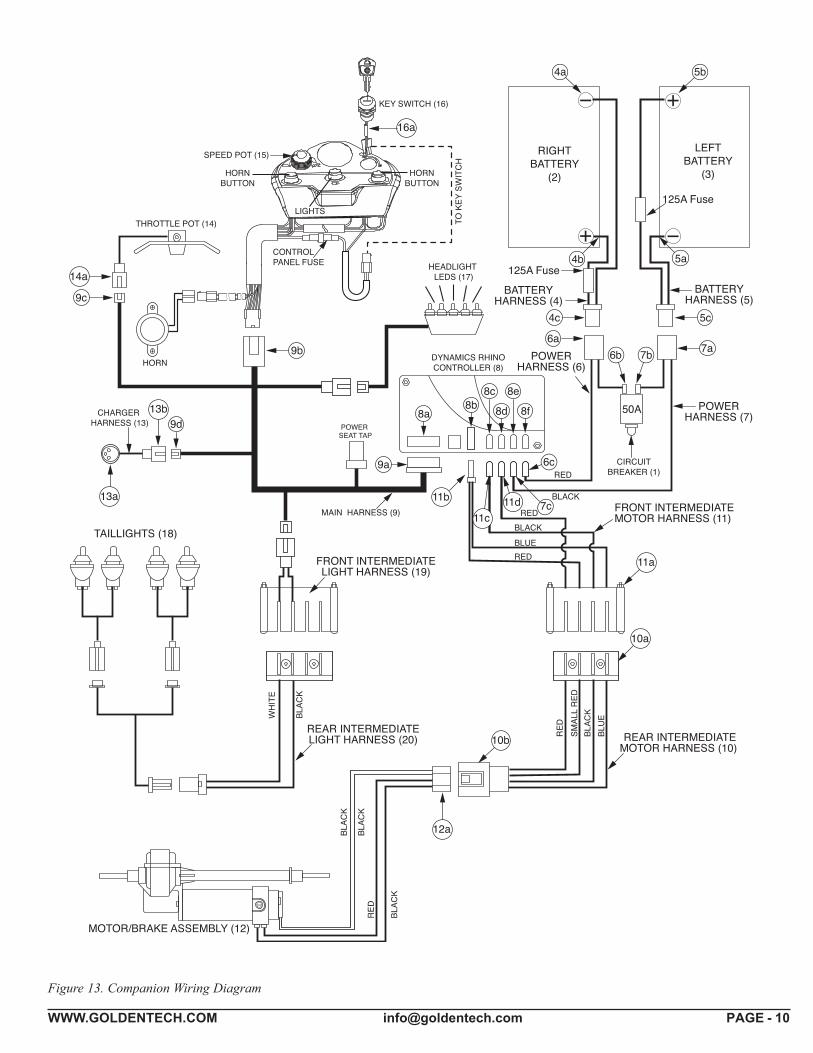
NOTE: The number after the component refers to the components position on figure 13 on page 10.
• Circuit Breaker (1) SE06E602• 12V/U-1 Batteries (2 and 3) MBE-BATTU1• Battery Harnesses (4 and 5) (4) SE06A612 Battery Cable Left (5) SE06A614 Battery Cable Right • Power Harnesses (6 and 7) (6 & 7 sold as set) SE06E602• Dynamics R-Series Controller (8) 3051600170• Main Harness (9) All models: SE08A601ASB• Rear Intermediate Motor Harness (10) SE06E604• Front Intermediate Motor Harness (11) SE06E606• Motor/Brake Assembly (12) MBX-CMBAR-2• Charger Harness (13) SE06A610• Throttle Pot (14) SE06E603• Speed Pot (15) N/A• Key Switch (16) MBH-C40-KSWITCH• Headlight LED (17) SE06E605• Taillights (18) SE06E502 Tail Light Assembly• Tail Light Lenses SE06A505 (Left) SE06A504 (Right)• Harness, Tail Light w/bulb SE06A620 ***24-volt/5-watt bulb • Front Intermediate Light Harness (19) SE06E608• Rear Intermediate Light Harness (20) SE06E607• Off-Board Battery Charger MBE-MRC4
WWW.GOLDENTECH.COM [email protected] PAGE - 5
NOTE: The number after each component refers to thecomponents position in figure 13 on page 10.
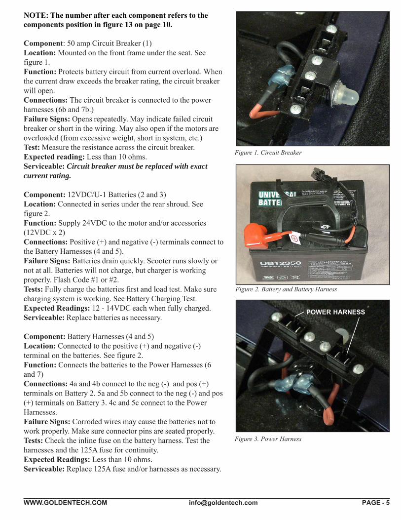
Component: 50 amp Circuit Breaker (1)Location: Mounted on the front frame under the seat. Seefigure 1.Function: Protects battery circuit from current overload. Whenthe current draw exceeds the breaker rating, the circuit breakerwill open.Connections: The circuit breaker is connected to the powerharnesses (6b and 7b.)Failure Signs: Opens repeatedly. May indicate failed circuitbreaker or short in the wiring. May also open if the motors areoverloaded (from excessive weight, short in system, etc.)Test: Measure the resistance across the circuit breaker.Expected reading: Less than 10 ohms.Serviceable: Circuit breaker must be replaced with exactcurrent rating.
Component: 12VDC/U-1 Batteries (2 and 3)Location: Connected in series under the rear shroud. Seefigure 2.Function: Supply 24VDC to the motor and/or accessories(12VDC x 2)Connections: Positive (+) and negative (-) terminals connect tothe Battery Harnesses (4 and 5).Failure Signs: Batteries drain quickly. Scooter runs slowly ornot at all. Batteries will not charge, but charger is workingproperly. Flash Code #1 or #2.Tests: Fully charge the batteries first and load test. Make surecharging system is working. See Battery Charging Test.Expected Readings: 12 - 14VDC each when fully charged.Serviceable: Replace batteries as necessary.
Component: Battery Harnesses (4 and 5)Location: Connected to the positive (+) and negative (-)terminal on the batteries. See figure 2.Function: Connects the batteries to the Power Harnesses (6and 7)Connections: 4a and 4b connect to the neg (-) and pos (+)terminals on Battery 2. 5a and 5b connect to the neg (-) and pos(+) terminals on Battery 3. 4c and 5c connect to the PowerHarnesses.Failure Signs: Corroded wires may cause the batteries not towork properly. Make sure connector pins are seated properly.Tests: Check the inline fuse on the battery harness. Test theharnesses and the 125A fuse for continuity.Expected Readings: Less than 10 ohms.Serviceable: Replace 125A fuse and/or harnesses as necessary.
Figure 1. Circuit Breaker
Figure 2. Battery and Battery Harness
Figure 3. Power Harness
POWER HARNESS
WWW.GOLDENTECH.COM [email protected] PAGE - 6
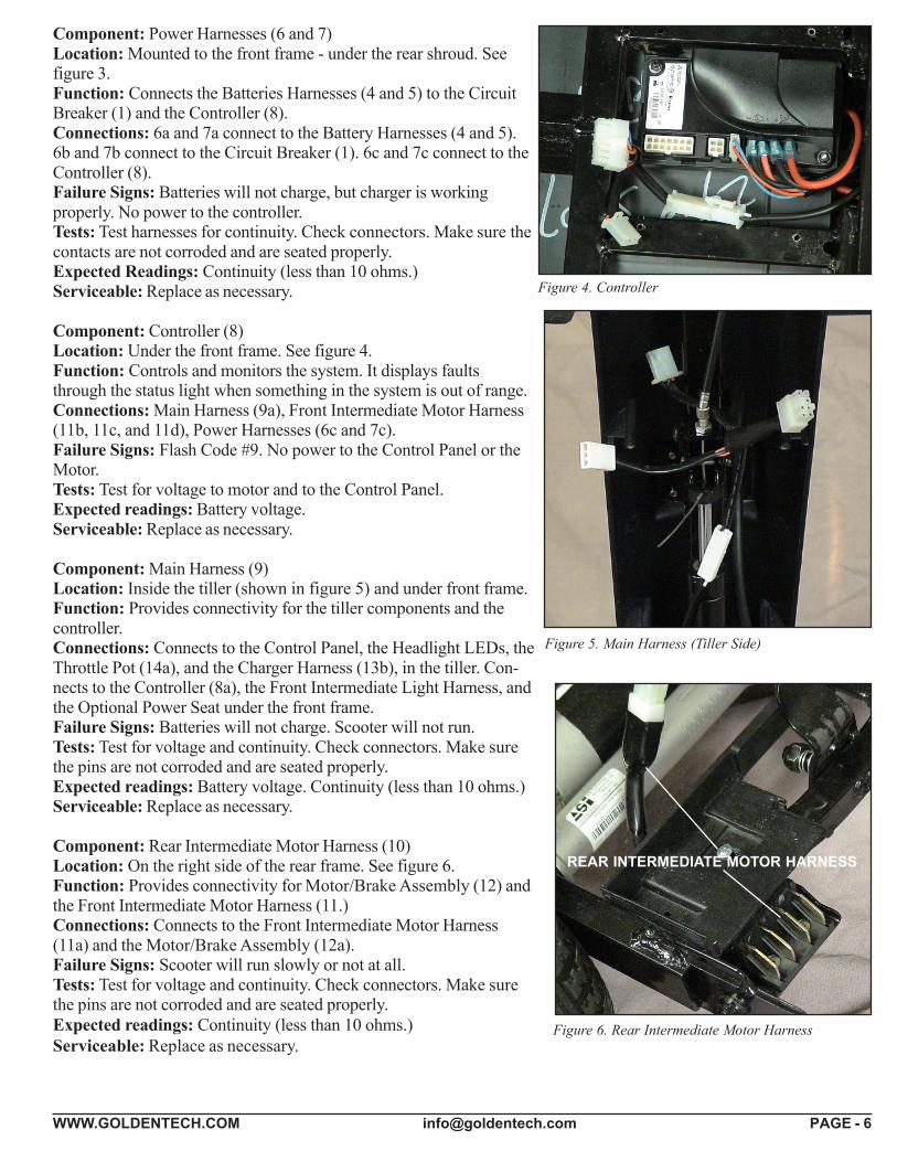
Component: Power Harnesses (6 and 7)Location: Mounted to the front frame - under the rear shroud. Seefigure 3.Function: Connects the Batteries Harnesses (4 and 5) to the CircuitBreaker (1) and the Controller (8).Connections: 6a and 7a connect to the Battery Harnesses (4 and 5).6b and 7b connect to the Circuit Breaker (1). 6c and 7c connect to theController (8).Failure Signs: Batteries will not charge, but charger is workingproperly. No power to the controller.Tests: Test harnesses for continuity. Check connectors. Make sure thecontacts are not corroded and are seated properly.Expected Readings: Continuity (less than 10 ohms.)Serviceable: Replace as necessary.
Component: Controller (8)Location: Under the front frame. See figure 4.Function: Controls and monitors the system. It displays faultsthrough the status light when something in the system is out of range.Connections: Main Harness (9a), Front Intermediate Motor Harness(11b, 11c, and 11d), Power Harnesses (6c and 7c).Failure Signs: Flash Code #9. No power to the Control Panel or theMotor.Tests: Test for voltage to motor and to the Control Panel.Expected readings: Battery voltage.Serviceable: Replace as necessary.
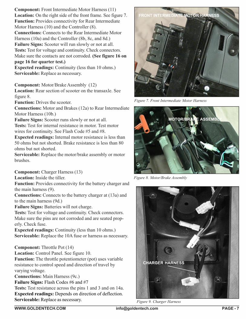
Component: Main Harness (9)Location: Inside the tiller (shown in figure 5) and under front frame.Function: Provides connectivity for the tiller components and thecontroller.Connections: Connects to the Control Panel, the Headlight LEDs, theThrottle Pot (14a), and the Charger Harness (13b), in the tiller. Con-nects to the Controller (8a), the Front Intermediate Light Harness, andthe Optional Power Seat under the front frame.Failure Signs: Batteries will not charge. Scooter will not run.Tests: Test for voltage and continuity. Check connectors. Make surethe pins are not corroded and are seated properly.Expected readings: Battery voltage. Continuity (less than 10 ohms.)Serviceable: Replace as necessary.
Component: Rear Intermediate Motor Harness (10)Location: On the right side of the rear frame. See figure 6.Function: Provides connectivity for Motor/Brake Assembly (12) andthe Front Intermediate Motor Harness (11.)Connections: Connects to the Front Intermediate Motor Harness(11a) and the Motor/Brake Assembly (12a).Failure Signs: Scooter will run slowly or not at all.Tests: Test for voltage and continuity. Check connectors. Make surethe pins are not corroded and are seated properly.Expected readings: Continuity (less than 10 ohms.)Serviceable: Replace as necessary.
Figure 4. Controller
Figure 5. Main Harness (Tiller Side)
Figure 6. Rear Intermediate Motor Harness
REAR INTERMEDIATE MOTOR HARNESS
WWW.GOLDENTECH.COM [email protected] PAGE - 7
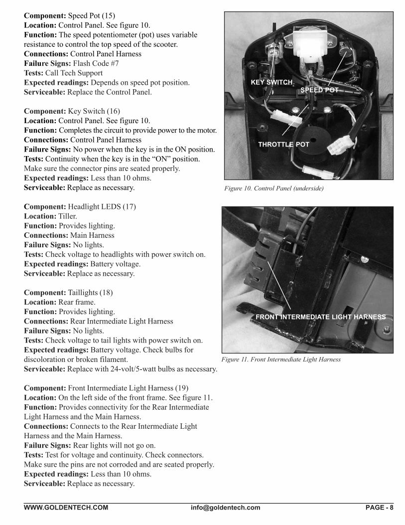
Component: Front Intermediate Motor Harness (11)Location: On the right side of the front frame. See figure 7. FRONT INTERMEDIATE MOTOR HARNESSFunction: Provides connectivity for Rear IntermediateMotor Harness (10) and the Controller (8).Connections: Connects to the Rear Intermediate MotorHarness (10a) and the Controller (8b, 8c, and 8d.)Failure Signs: Scooter will run slowly or not at all.Tests: Test for voltage and continuity. Check connectors.Make sure the contacts are not corroded. (See figure 16 onpage 16 for quarter test.)Expected readings: Continuity (less than 10 ohms.)Serviceable: Replace as necessary.
Component: Motor/Brake Assembly (12)Location: Rear section of scooter on the transaxle. Seefigure 8.Function: Drives the scooter.Connections: Motor and Brakes (12a) to Rear IntermediateMotor Harness (10b.)Failure Signs: Scooter runs slowly or not at all.Tests: Test for internal resistance in motor. Test motorwires for continuity. See Flash Code #5 and #8.Expected readings: Internal motor resistance is less than50 ohms but not shorted. Brake resistance is less than 80ohms but not shorted.Serviceable: Replace the motor/brake assembly or motorbrushes.
Component: Charger Harness (13)Location: Inside the tiller.Function: Provides connectivity for the battery charger andthe main harness (9).Connections: Connects to the battery charger at (13a) andto the main harness (9d.)Failure Signs: Batteries will not charge.Tests: Test for voltage and continuity. Check connectors.Make sure the pins are not corroded and are seated prop-erly. Check fuse.Expected readings: Continuity (less than 10 ohms.)Serviceable: Replace the 10A fuse or harness as necessary.
Component: Throttle Pot (14)Location: Control Panel. See figure 10.Function: The throttle potentiometer (pot) uses variableresistance to control speed and direction of travel byvarying voltage.Connections: Main Harness (9c.)Failure Signs: Flash Codes #6 and #7Tests: Test resistance across the pins 1 and 3 and on 14a.Expected readings: Depends on direction of deflection.Serviceable: Replace as necessary.
Figure 7. Front Intermediate Motor Harness
Figure 8. Motor/Brake Assembly
Figure 9. Charger Harness
CHARGER HARNESS
MOTOR/BRAKE ASSEMBLY
WWW.GOLDENTECH.COM [email protected] PAGE - 8
Component: Speed Pot (15)Location: Control Panel. See figure 10.Function: The speed potentiometer (pot) uses variableresistance to control the top speed of the scooter.Connections: Control Panel HarnessFailure Signs: Flash Code #7Tests: Call Tech SupportExpected readings: Depends on speed pot position.Serviceable: Replace the Control Panel.
Component: Key Switch (16)Location: Control Panel. See figure 10.Function: Completes the circuit to provide power to the motor.Connections: Control Panel HarnessFailure Signs: No power when the key is in the ON position.Tests: Continuity when the key is in the “ON” position.Make sure the connector pins are seated properly.Expected readings: Less than 10 ohms.Serviceable: Replace as necessary.
Component: Headlight LEDS (17)Location: Tiller.Function: Provides lighting.Connections: Main HarnessFailure Signs: No lights.Tests: Check voltage to headlights with power switch on.Expected readings: Battery voltage.Serviceable: Replace as necessary.
Component: Taillights (18)Location: Rear frame.Function: Provides lighting.Connections: Rear Intermediate Light HarnessFailure Signs: No lights.Tests: Check voltage to tail lights with power switch on.Expected readings: Battery voltage. Check bulbs fordiscoloration or broken filament.Serviceable: Replace with 24-volt/5-watt bulbs as necessary.
Component: Front Intermediate Light Harness (19)Location: On the left side of the front frame. See figure 11.Function: Provides connectivity for the Rear IntermediateLight Harness and the Main Harness.Connections: Connects to the Rear Intermediate LightHarness and the Main Harness.Failure Signs: Rear lights will not go on.Tests: Test for voltage and continuity. Check connectors.Make sure the pins are not corroded and are seated properly.Expected readings: Less than 10 ohms.Serviceable: Replace as necessary.
Figure 10. Control Panel (underside)
Figure 11. Front Intermediate Light Harness
THROTTLE POT
SPEED POTKEY SWITCH
FRONT INTERMEDIATE LIGHT HARNESS
WWW.GOLDENTECH.COM [email protected] PAGE - 9
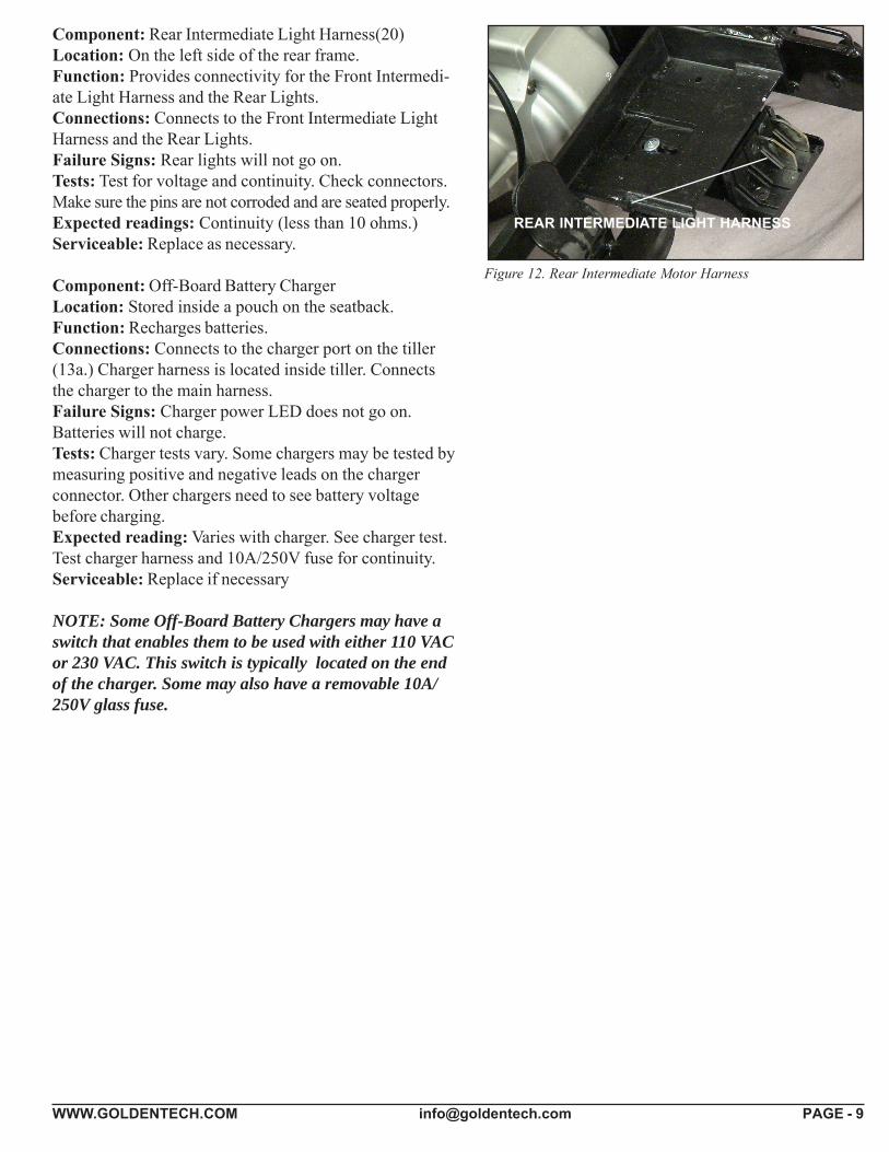
Component: Rear Intermediate Light Harness(20)Location: On the left side of the rear frame.Function: Provides connectivity for the Front Intermedi-ate Light Harness and the Rear Lights.Connections: Connects to the Front Intermediate LightHarness and the Rear Lights.Failure Signs: Rear lights will not go on.Tests: Test for voltage and continuity. Check connectors.Make sure the pins are not corroded and are seated properly.Expected readings: Continuity (less than 10 ohms.)Serviceable: Replace as necessary.
Component: Off-Board Battery ChargerLocation: Stored inside a pouch on the seatback.Function: Recharges batteries.Connections: Connects to the charger port on the tiller(13a.) Charger harness is located inside tiller. Connectsthe charger to the main harness.Failure Signs: Charger power LED does not go on.Batteries will not charge.Tests: Charger tests vary. Some chargers may be tested bymeasuring positive and negative leads on the chargerconnector. Other chargers need to see battery voltagebefore charging.Expected reading: Varies with charger. See charger test.Test charger harness and 10A/250V fuse for continuity.Serviceable: Replace if necessary
NOTE: Some Off-Board Battery Chargers may have aswitch that enables them to be used with either 110 VACor 230 VAC. This switch is typically located on the endof the charger. Some may also have a removable 10A/250V glass fuse.
Figure 12. Rear Intermediate Motor Harness
REAR INTERMEDIATE LIGHT HARNESS
WWW.GOLDENTECH.COM [email protected] PAGE - 10
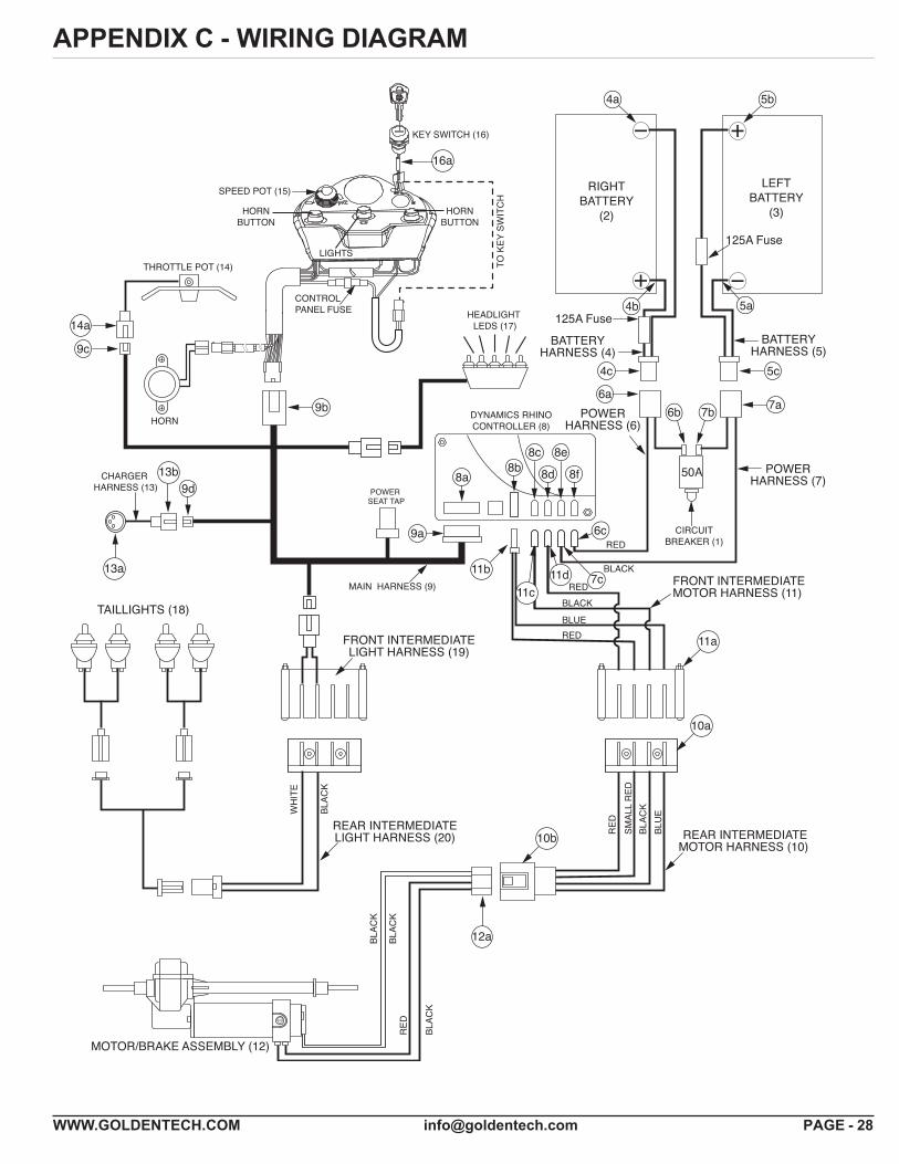
Figure 13. Companion Wiring Diagram
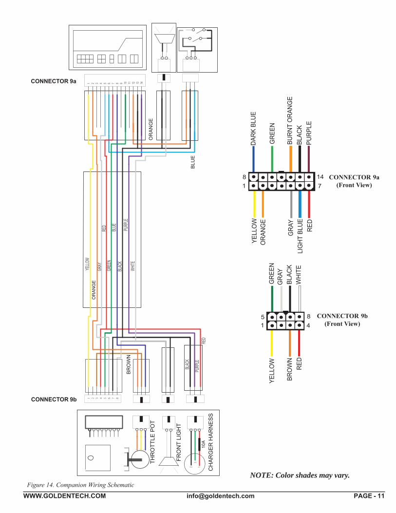
WWW.GOLDENTECH.COM [email protected] PAGE - 11Figure 14. Companion Wiring Schematic
� ��
�
� �� �
�
��
��
�
�
� �
��
�
�
���
��
��
���
��
��
��
��
���
��
��
�
��
��
����
��
�
���
��
�
��
���
�
��
�
��
��
�
���
��
��
��
���
�
��
CONNECTOR 9b(Front View)
CONNECTOR 9a(Front View)
CONNECTOR 9a
CONNECTOR 9b
NOTE: Color shades may vary.
WWW.GOLDENTECH.COM [email protected] PAGE - 12
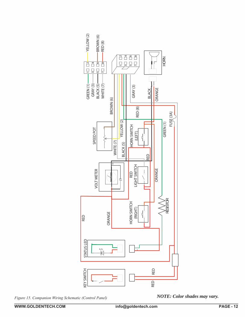
Figure 15. Companion Wiring Schematic (Control Panel)
HO
RNRE
SIST
OR
NOTE: Color shades may vary.
WWW.GOLDENTECH.COM [email protected] PAGE - 13
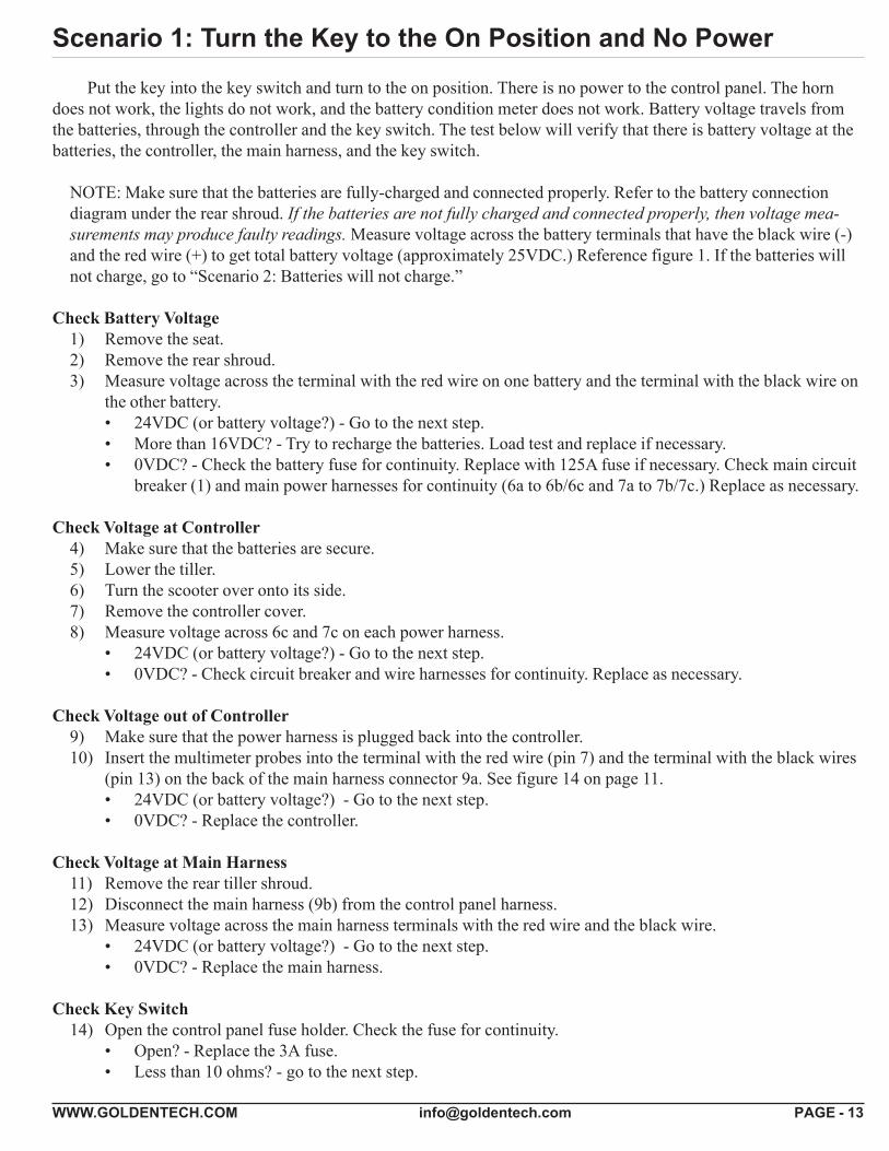
Scenario 1: Turn the Key to the On Position and No Power
Put the key into the key switch and turn to the on position. There is no power to the control panel. The horndoes not work, the lights do not work, and the battery condition meter does not work. Battery voltage travels fromthe batteries, through the controller and the key switch. The test below will verify that there is battery voltage at thebatteries, the controller, the main harness, and the key switch.
NOTE: Make sure that the batteries are fully-charged and connected properly. Refer to the battery connectiondiagram under the rear shroud. If the batteries are not fully charged and connected properly, then voltage mea-surements may produce faulty readings. Measure voltage across the battery terminals that have the black wire (-)and the red wire (+) to get total battery voltage (approximately 25VDC.) Reference figure 1. If the batteries willnot charge, go to “Scenario 2: Batteries will not charge.”
Check Battery Voltage1) Remove the seat.2) Remove the rear shroud.3) Measure voltage across the terminal with the red wire on one battery and the terminal with the black wire on
the other battery.• 24VDC (or battery voltage?) - Go to the next step.• More than 16VDC? - Try to recharge the batteries. Load test and replace if necessary.• 0VDC? - Check the battery fuse for continuity. Replace with 125A fuse if necessary. Check main circuit
breaker (1) and main power harnesses for continuity (6a to 6b/6c and 7a to 7b/7c.) Replace as necessary.
Check Voltage at Controller4) Make sure that the batteries are secure.5) Lower the tiller.6) Turn the scooter over onto its side.7) Remove the controller cover.8) Measure voltage across 6c and 7c on each power harness.
• 24VDC (or battery voltage?) - Go to the next step.• 0VDC? - Check circuit breaker and wire harnesses for continuity. Replace as necessary.
Check Voltage out of Controller9) Make sure that the power harness is plugged back into the controller.10) Insert the multimeter probes into the terminal with the red wire (pin 7) and the terminal with the black wires
(pin 13) on the back of the main harness connector 9a. See figure 14 on page 11.• 24VDC (or battery voltage?) - Go to the next step.• 0VDC? - Replace the controller.
Check Voltage at Main Harness11) Remove the rear tiller shroud.12) Disconnect the main harness (9b) from the control panel harness.13) Measure voltage across the main harness terminals with the red wire and the black wire.
• 24VDC (or battery voltage?) - Go to the next step.• 0VDC? - Replace the main harness.
Check Key Switch14) Open the control panel fuse holder. Check the fuse for continuity.
• Open? - Replace the 3A fuse.• Less than 10 ohms? - go to the next step.
WWW.GOLDENTECH.COM [email protected] PAGE - 14
15) Disconnect the key switch connector from the control panel harness. Make sure that the key is in the onposition. Measure continuity across the two pins on the key switch connector.Continuity? - Replace the control panel wiring harness.Open? - Replace the key switch.
Scenario 2: Batteries Will Not ChargeMost battery chargers need to "see" least 16VDC at the charger port. Otherwise, they may not send a charging
current to the batteries. This test will ensure that the battery voltage is making it to the charger port. You will need tocheck battery voltage at the batteries, at the controller, out of the controller, and at the charger port.
Check Battery Charger Voltage1) Remove the seat.2) Remove the rear shroud.3) Plug the charger into the charger port and then into a wall outlet.4) Measure voltage across the terminal with the red wire on one battery and the terminal with the black wire on
the other battery. Does the voltage increase?• Yes? - Load test the batteries and replace as necessary.• No? - But there is voltage. If the voltage is lower than 16VDC, then replace the batteries. If the voltage
is 16VDC or greater, then go to the next step.• No? - And there is no voltage. Check the circuit breaker, the wire harnesses, and the battery harness fuse
for continuity. Replace the individual components as necessary.
Check Voltage Into the Controller5) Make sure the batteries are secure.6) Lower the tiller.7) Turn the scooter over onto its side.8) Remove the controller cover.9) Measure voltage across 6c and 7c.
24VDC (or battery voltage?) - Go to the next step.0VDC? - Check circuit breaker and wire harnesses for continuity. Replace as necessary.
Check Voltage Out of the Controller10) Insert the multimeter probes into the terminal with the red wire (pin 7) and the terminal with the black wires
(pin 13) on the back of the main harness connector 9a. See figure 14 on page 11.• 24VDC (or battery voltage?) - Go to the next step.• 0VDC? - Replace the controller.
Check Voltage at the Main Harness11) Remove the rear tiller shroud.12) Disconnect the charger harness from the main harness.13) Measure voltage across the terminal with the black wire (pin 7) and the red wire (pin 4) on the main harness
connector 9d. See figure 14 on page 11.• 24VDC (or battery voltage?) - Go to the next step.• 0VDC? - Replace the main harness.
14) Check the charger harness fuse for continuity.• Continuity? - Replace the charger harness.• Open? - Replace the 10A fuse.
WWW.GOLDENTECH.COM [email protected] PAGE - 15
FLASH CODESThe controller uses an LED on the console to indicate the status of the system. When the key is in the key
switch and the light is solid green, the power is on and the system is running normally. When the controller noticesthat there is a malfunction in the system, it will flash a code when the key is inserted into the key switch. For ex-ample, when it flashes five times and stops, that indicates flash code #5 – Brake Fault.
The following flash codes are used to help diagnose system errors:Flash Code #1 – Batteries Low (Scooter will operate)Flash Code #2 – Batteries Very Low (Scooter will not operate)Flash Code #3 – High Battery VoltageFlash Code #4 – Current limit timeoutFlash Code #5 – Motor Brake FaultFlash Code #6 – Paddle Fault (out of neutral)Flash Code #7 – Paddle Voltage FaultFlash Code #8 – Motor Voltage Fault (Open)Flash Code #9 – Controller Fault
FLASH CODE #1 – BATTERIES LOW (SCOOTER MAY DRIVE SLOWLY.)This Flash Code appears when the battery voltage drops below a certain level. Recharge the batteries immedi-
ately. If they batteries will not recharge, then load test them or refer to “Scenario 2: Batteries will not Charge.”
FLASH CODE #2 – BATTERIES LOW (SCOOTER WILL NOT OPERATE.)This Flash Code appears when the battery voltage drops lower than Flash Code #1. Recharge the batteries
immediately. If the batteries will not recharge, load test them or refer to “Scenario 2: Batteries will not Charge.”
FLASH CODE #3 - HIGH BATTERY VOLTAGEThis Flash Code appears when the battery voltage climbs above 26VDC.1) Insert the key into the key switch and turn it to the on position. Allow the battery level to drop. Do not
allow the battery voltage to fall into the red area on the battery meter.2) Check the battery charger. Make sure it is an approved charger.
FLASH CODE #4 - CURRENT LIMIT TIMEOUTThis Flash Code appears when the motor has been exceeding it’s maximum current rating for too long. This
may be due to a faulty motor, poor battery condition, excessive uphill driving, or excessive weight. First turn off thescooter and allow it to cool for ten minutes. If this does not work, use the following procedure.
1) Remove the seat.2) Remove the rear shroud.3) Inspect the connection between the motor/brake assembly (12a) and the rear intermediate motor harness
(10b). Are either connectors discolored or melted?• Yes? - Replace motor/brake assembly or rear intermediate motor harness as necessary.• No? - Go to the next step.
4) Disconnect the motor (12a) from the rear intermediate motor harness (10b).5) Measure resistance across the two pins on connector 12a that have the thick black wire and the thick red wire
(internal resistance of the motor.)• 50 ohms or less but not shorted? (NOTE: Can be as low as 0.2 ohms.) – Go to step 7.• Out of that range? – Go to the next step.
6) Remove the brushes from the motor and inspect them.• Worn below 0.25 in. or physically damaged? – Replace the brushes.• Not worn below 0.25 in. or physically damaged? - Replace the motor/brake assembly.
WWW.GOLDENTECH.COM [email protected] PAGE - 16
7) Make sure that the batteries are secure.8) Lower the tiller.9) Turn the scooter over onto its side.10) Remove the controller cover.11) Disconnect the front intermediate motor harness
(11c and 11d) from the controller.12) Make sure that the pins are seated properly on10b.
Check the continuity between 11c/11d and 10b.• 10 ohms or less? – Replace the controller.• Open? – Go the next step.
13) Turn the scooter back over.14) Remove the batteries.15) Separate the front and rear sections of the
scooter.16) Inspect the front and rear intermediate motor
harness connectors. Are they discolored or corroded?• Yes? - Replace as necessary.• No? - Go to the next step.
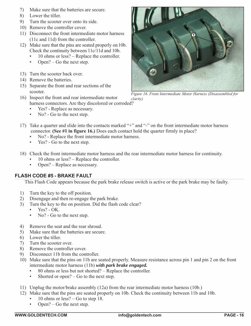
17) Take a quarter and slide into the contacts marked “+” and “-” on the front intermediate motor harness connector. (See #1 in figure 16.) Does each contact hold the quarter firmly in place?• No? - Replace the front intermediate motor harness.• Yes? - Go to the next step.
18) Check the front intermediate motor harness and the rear intermediate motor harness for continuity.• 10 ohms or less? – Replace the controller.• Open? – Replace as necessary.
FLASH CODE #5 - BRAKE FAULTThis Flash Code appears because the park brake release switch is active or the park brake may be faulty.
1) Turn the key to the off position.2) Disengage and then re-engage the park brake.3) Turn the key to the on position. Did the flash code clear?
• Yes? - OK.• No? - Go to the next step.
4) Remove the seat and the rear shroud.5) Make sure that the batteries are secure.6) Lower the tiller.7) Turn the scooter over.8) Remove the controller cover.9) Disconnect 11b from the controller.10) Make sure that the pins on 11b are seated properly. Measure resistance across pin 1 and pin 2 on the front
intermediate motor harness (11b) with park brake engaged.• 80 ohms or less but not shorted? – Replace the controller.• Shorted or open? – Go to the next step.
11) Unplug the motor/brake assembly (12a) from the rear intermediate motor harness (10b.)12) Make sure that the pins are seated properly on 10b. Check the continuity between 11b and 10b.
• 10 ohms or less? – Go to step 18.• Open? – Go the next step.
Figure 16. Front Intermediate Motor Harness (Disassembled forclarity)
1
WWW.GOLDENTECH.COM [email protected] PAGE - 17
13) Turn the scooter back over.14) Remove the batteries.15) Separate the front and rear frames.16) Inspect the connection between the front intermediate motor harness (11a) and the rear intermediate motor
harness (10a.) Make sure the contacts are not corroded. Take a quarter and slide into the contacts on 11anot marked “+” and “-” on the connector. (Similar to #1 in figure 16.) Does each contact hold the quarterfirmly in place?• No? - Replace the front intermediate motor harness.• Yes? - Go to the next step.
17) Check the front intermediate motor harness and the rear intermediate motor harness for continuity.• 10 ohms or less? – Go to the next step.• Open? – Replace as necessary.
18) Check the pins on the motor/brake assembly harness connector 12a. Make sure they are seated properly.19) Measure resistance across pin 1 and pin 2 (small black wires) on the motor/brake assembly harness (12a)
with park brake engaged.• 80 ohms or less but not shorted? – Replace the controller.• Shorted or open? – Replace the motor/brake assembly.
FLASH CODE #6 - PADDLE FAULT (OUT OF NEUTRAL)This Flash Code appears because the throttle control lever is not in the neutral position when the key is turned
to the on position.1) Turn the key to the off position.2) Make sure that the paddle pot is not obstructed and it can return to the neutral (center) position..3) Move the throttle pot forward and then reverse. Make sure that it is not obstructed. Does it spring back
to neutral position?• Yes? – Go to the next step.• No? – Check for obstructions. Adjust if necessary. Replace if the adjustment does not work or if
there are no obstructions.4) Turn the key to the on position. Does the code return?
• No? – OK• Yes? – Go to FLASH CODE #7 to test the paddle pot.
FLASH CODE #7 - PADDLE FAULT/SPEED CONTROL FAULT (VOLTAGE ERROR)This Flash Code appears because there is a fault with the throttle pot, the speed pot, or the associated wiring.
1) Remove the seat.2) Remove the rear shroud.3) Remove the batteries.4) Separate the front and rear frames.5) Turn over the front frame.6) Remove the controller cover.7) Turn the speed pot to full rabbit.8) Set your multimeter to measure resistance.9) Disconnect the main harness from the controller.10) Insert multimeter probes into the main harness connector 9a at pin 8 and pin 2 (blue wire and orange
wire.) See figures 13 and 14.• 5k ohm ±10%? - Note the resistance reading and go to the next step.• Outside that range? - Go to step 12.
WWW.GOLDENTECH.COM [email protected] PAGE - 18
11) Insert the multimeter probes into the main harness connector 9a at pin 1 and pin 8 (blue wire and yellowwire.) See figures 13 and 14. Note the resistance reading. Insert the multimeter probe into the main harnessconnector at pin 1 and pin 2 (yellow wire and orange wire.) Note the resistance reading.• Are both readings within 500 ohms of the resistance measured in step 10? - Replace the controller.• Are either readings outside that range? - Go to the next step.
12) Remove the 8 screws that fasten the back tiller shroud to the front tiller shroud.13) Disconnect the main harness (9b) from the throttle pot (14a.)14) Insert multimeter probes into the throttle pot connector (14a) at the blue wire and the orange wire (outside
two pins.)• 5k ohm ±10%? - Note the resistance reading and go to the next step.• Outside that range? - Replace the throttle pot.
15) Insert the multimeter probes into the throttle pot connector (14a) at the blue wire and the yellowwire. Note the resistance reading. Insert the multimeter probe into the main harness connector at the yellowwire and the orange wire. Note the resistance reading.• Are both readings within 500 ohms of the resistance measured in step 14? - Go to the next step.• Are either readings outside that range? - Replace the throttle pot.
16) Check the orange, blue, and yellow wires on the main harness for continuity.10 ohms or less on each one? - Replace the speed pot.Open on any wire? - Replace the main harness.
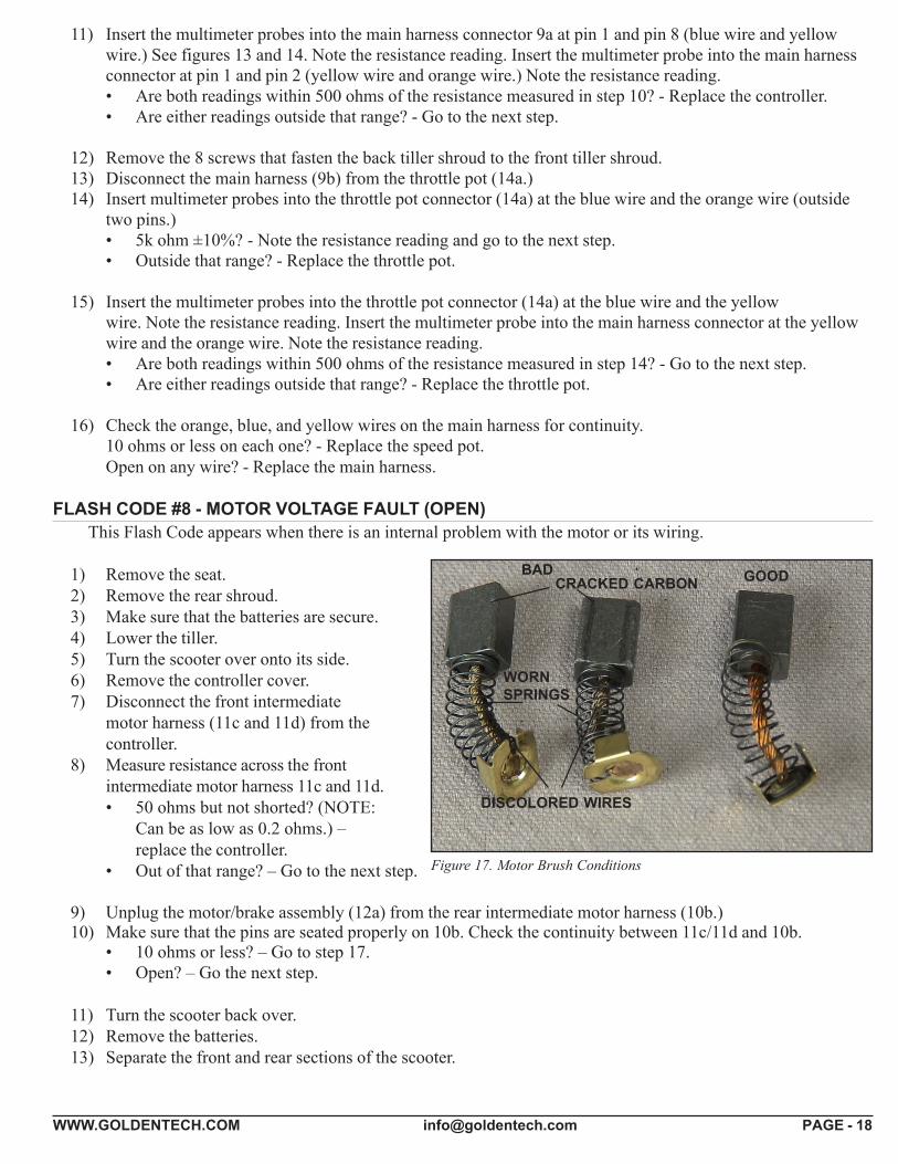
FLASH CODE #8 - MOTOR VOLTAGE FAULT (OPEN)This Flash Code appears when there is an internal problem with the motor or its wiring.
1) Remove the seat.2) Remove the rear shroud.3) Make sure that the batteries are secure.4) Lower the tiller.5) Turn the scooter over onto its side.6) Remove the controller cover.7) Disconnect the front intermediate
motor harness (11c and 11d) from thecontroller.
8) Measure resistance across the frontintermediate motor harness 11c and 11d.• 50 ohms but not shorted? (NOTE:
Can be as low as 0.2 ohms.) –replace the controller.
• Out of that range? – Go to the next step.
9) Unplug the motor/brake assembly (12a) from the rear intermediate motor harness (10b.)10) Make sure that the pins are seated properly on 10b. Check the continuity between 11c/11d and 10b.
• 10 ohms or less? – Go to step 17.• Open? – Go the next step.
11) Turn the scooter back over.12) Remove the batteries.13) Separate the front and rear sections of the scooter.
Figure 17. Motor Brush Conditions
BAD GOOD
DISCOLORED WIRES
WORNSPRINGS
CRACKED CARBON
WWW.GOLDENTECH.COM [email protected] PAGE - 19
14) Inspect the front and rear intermediate motor harness connectors. Are they discolored or corroded?• No? - Replace as necessary.• Yes? - Go to the next step.
15) Take a quarter and slide into the contacts marked “+” and “-” on the front intermediate motor harness connector. (See #1 in figure 16.) Does each contact hold the quarter firmly in place?• No? - Replace the front intermediate motor harness.• Yes? - Go to the next step.
16) Check the front intermediate motor harness and the rear intermediate motor harness for continuity.• 10 ohms or less? – Go to the next step.• Open? – Replace as necessary.
17) Make sure that the pins are seated properly on 12a.18) Measure resistance across pin 1 (thick red wire) and pin 2 (thick black wire) on 12a.
• 50 ohms or less but not shorted? (NOTE: Can be as low as 0.2 ohms.) – Replace the controller.• Out of that range? – Go to the next step.
19) Remove the brushes from the motor and inspect them. See figure 17. Indications of a bad brush includebroken springs, cracked carbon, black or discolored wire, and black or discolored contacts.• Worn or physically damaged? – Replace the brushes.• Not worn or physically damaged? - Replace the motor/brake assembly.
FLASH CODE #9 - CONTROLLER FAULTThis Flash Code appears when the controller has an internal fault.
1) Remove the key from the key switch and allow the controller to cool down. If the code continues,then replace the controller.
WWW.GOLDENTECH.COM [email protected] PAGE - 20
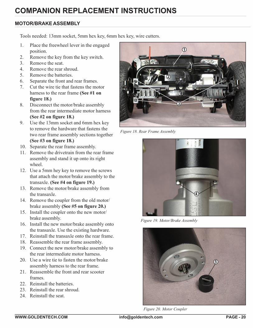
COMPANION REPLACEMENT INSTRUCTIONSMOTOR/BRAKE ASSEMBLY
Tools needed: 13mm socket, 5mm hex key, 6mm hex key, wire cutters.
1. Place the freewheel lever in the engagedposition.
2. Remove the key from the key switch.3. Remove the seat.4. Remove the rear shroud.5. Remove the batteries.6. Separate the front and rear frames.7. Cut the wire tie that fastens the motor
harness to the rear frame (See #1 onfigure 18.)
8. Disconnect the motor/brake assemblyfrom the rear intermediate motor harness(See #2 on figure 18.)
9. Use the 13mm socket and 6mm hex keyto remove the hardware that fastens thetwo rear frame assembly sections together(See #3 on figure 18.)
10. Separate the rear frame assembly.11. Remove the drivetrain from the rear frame
assembly and stand it up onto its rightwheel.
12. Use a 5mm hey key to remove the screwsthat attach the motor/brake assembly to thetransaxle. (See #4 on figure 19.)
13. Remove the motor/brake assembly fromthe transaxle.
14. Remove the coupler from the old motor/brake assembly (See #5 on figure 20.)
15. Install the coupler onto the new motor/brake assembly.
16. Install the new motor/brake assembly ontothe transaxle. Use the existing hardware.
17. Reinstall the transaxle onto the rear frame.18. Reassemble the rear frame assembly.19. Connect the new motor/brake assembly to
the rear intermediate motor harness.20. Use a wire tie to fasten the motor/brake
assembly harness to the rear frame.21. Reassemble the front and rear scooter
frames.22. Reinstall the batteries.23. Reinstall the rear shroud.24. Reinstall the seat.
1
2
3
4
5
Figure 18. Rear Frame Assembly
Figure 20. Motor Coupler
Figure 19. Motor/Brake Assembly
WWW.GOLDENTECH.COM [email protected] PAGE - 21
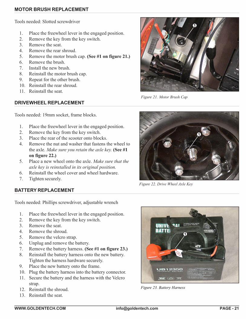
Figure 22. Drive Wheel Axle Key
MOTOR BRUSH REPLACEMENT
Tools needed: Slotted screwdriver
1. Place the freewheel lever in the engaged position.2. Remove the key from the key switch.3. Remove the seat.4. Remove the rear shroud.5. Remove the motor brush cap. (See #1 on figure 21.)6. Remove the brush.7. Install the new brush.8. Reinstall the motor brush cap.9. Repeat for the other brush.10. Reinstall the rear shroud.11. Reinstall the seat.
DRIVEWHEEL REPLACEMENT
Tools needed: 19mm socket, frame blocks.
1. Place the freewheel lever in the engaged position.2. Remove the key from the key switch.3. Place the rear of the scooter onto blocks.4. Remove the nut and washer that fastens the wheel to
the axle. Make sure you retain the axle key. (See #1on figure 22.)
5. Place a new wheel onto the axle. Make sure that theaxle key is reinstalled in its original position.
6. Reinstall the wheel cover and wheel hardware.7. Tighten securely.
BATTERY REPLACEMENT
Tools needed: Phillips screwdriver, adjustable wrench
1. Place the freewheel lever in the engaged position.2. Remove the key from the key switch.3. Remove the seat.4. Remove the shroud.5. Remove the velcro strap.6. Unplug and remove the battery.7. Remove the battery harness. (See #1 on figure 23.)8. Reinstall the battery harness onto the new battery.
Tighten the harness hardware securely.9. Place the new battery onto the frame.10. Plug the battery harness into the battery connector.11. Secure the battery and the harness with the Velcro
strap.12. Reinstall the shroud.13. Reinstall the seat.
Figure 21. Motor Brush Cap
1
Figure 23. Battery Harness
1
1
WWW.GOLDENTECH.COM [email protected] PAGE - 22
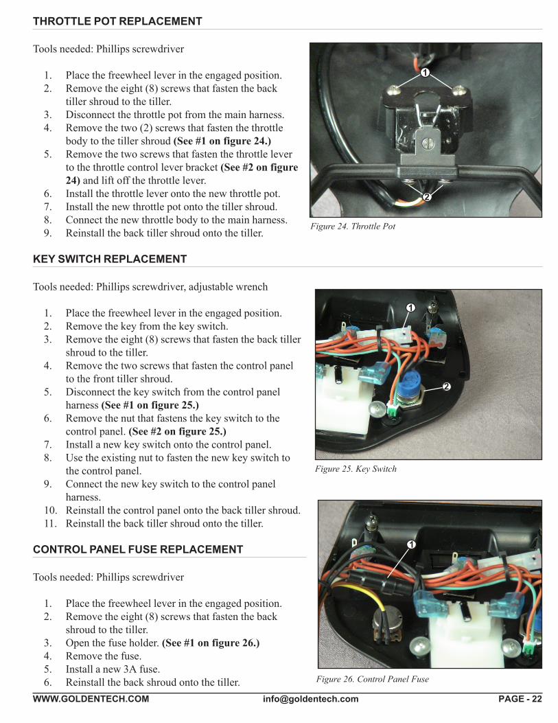
THROTTLE POT REPLACEMENT
Tools needed: Phillips screwdriver
1. Place the freewheel lever in the engaged position.2. Remove the eight (8) screws that fasten the back
tiller shroud to the tiller.3. Disconnect the throttle pot from the main harness.4. Remove the two (2) screws that fasten the throttle
body to the tiller shroud (See #1 on figure 24.)5. Remove the two screws that fasten the throttle lever
to the throttle control lever bracket (See #2 on figure24) and lift off the throttle lever.
6. Install the throttle lever onto the new throttle pot.7. Install the new throttle pot onto the tiller shroud.8. Connect the new throttle body to the main harness.9. Reinstall the back tiller shroud onto the tiller.
KEY SWITCH REPLACEMENT
Tools needed: Phillips screwdriver, adjustable wrench
1. Place the freewheel lever in the engaged position.2. Remove the key from the key switch.3. Remove the eight (8) screws that fasten the back tiller
shroud to the tiller.4. Remove the two screws that fasten the control panel
to the front tiller shroud.5. Disconnect the key switch from the control panel
harness (See #1 on figure 25.)6. Remove the nut that fastens the key switch to the
control panel. (See #2 on figure 25.)7. Install a new key switch onto the control panel.8. Use the existing nut to fasten the new key switch to
the control panel.9. Connect the new key switch to the control panel
harness.10. Reinstall the control panel onto the back tiller shroud.11. Reinstall the back tiller shroud onto the tiller.
CONTROL PANEL FUSE REPLACEMENT
Tools needed: Phillips screwdriver
1. Place the freewheel lever in the engaged position.2. Remove the eight (8) screws that fasten the back
shroud to the tiller.3. Open the fuse holder. (See #1 on figure 26.)4. Remove the fuse.5. Install a new 3A fuse.6. Reinstall the back shroud onto the tiller.
Figure 25. Key Switch
Figure 26. Control Panel Fuse
2
1
Figure 24. Throttle Pot
1
2
1
WWW.GOLDENTECH.COM [email protected] PAGE - 23
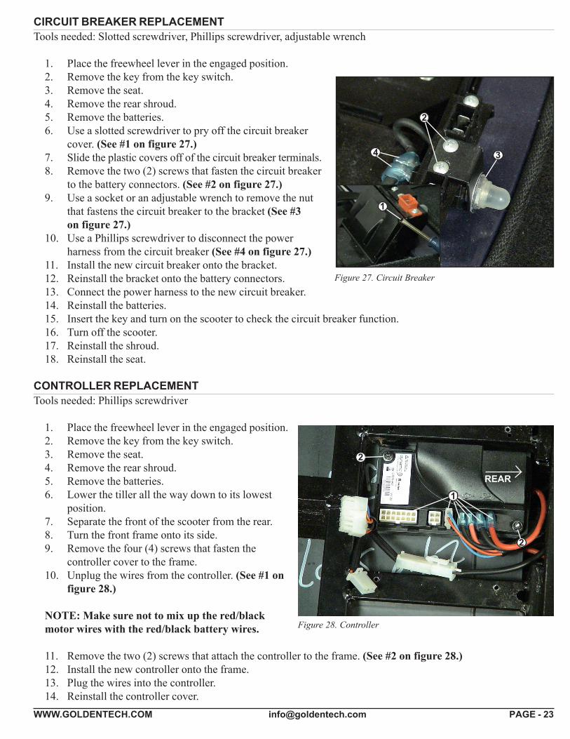
CIRCUIT BREAKER REPLACEMENTTools needed: Slotted screwdriver, Phillips screwdriver, adjustable wrench
1. Place the freewheel lever in the engaged position.2. Remove the key from the key switch.3. Remove the seat.4. Remove the rear shroud.5. Remove the batteries.6. Use a slotted screwdriver to pry off the circuit breaker
cover. (See #1 on figure 27.)7. Slide the plastic covers off of the circuit breaker terminals.8. Remove the two (2) screws that fasten the circuit breaker
to the battery connectors. (See #2 on figure 27.)9. Use a socket or an adjustable wrench to remove the nut
that fastens the circuit breaker to the bracket (See #3on figure 27.)
10. Use a Phillips screwdriver to disconnect the powerharness from the circuit breaker (See #4 on figure 27.)
11. Install the new circuit breaker onto the bracket.12. Reinstall the bracket onto the battery connectors.13. Connect the power harness to the new circuit breaker.14. Reinstall the batteries.15. Insert the key and turn on the scooter to check the circuit breaker function.16. Turn off the scooter.17. Reinstall the shroud.18. Reinstall the seat.
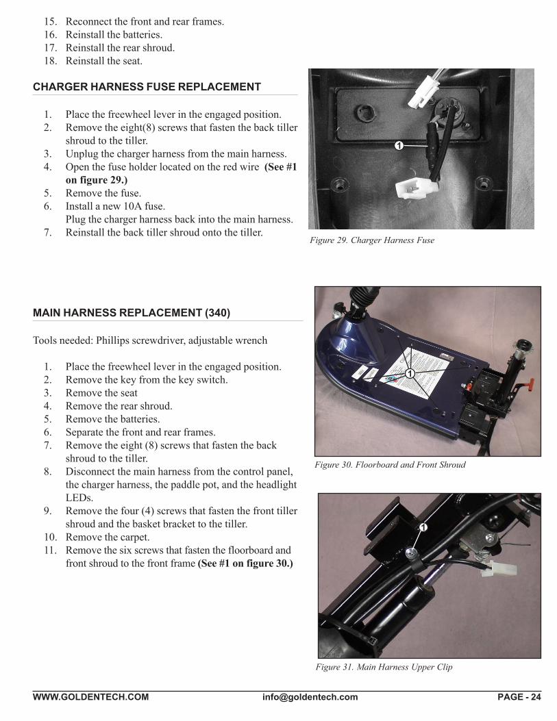
CONTROLLER REPLACEMENTTools needed: Phillips screwdriver
1. Place the freewheel lever in the engaged position.2. Remove the key from the key switch.3. Remove the seat.4. Remove the rear shroud.5. Remove the batteries.6. Lower the tiller all the way down to its lowest
position.7. Separate the front of the scooter from the rear.8. Turn the front frame onto its side.9. Remove the four (4) screws that fasten the
controller cover to the frame.10. Unplug the wires from the controller. (See #1 on
figure 28.)
NOTE: Make sure not to mix up the red/blackmotor wires with the red/black battery wires.
11. Remove the two (2) screws that attach the controller to the frame. (See #2 on figure 28.)12. Install the new controller onto the frame.13. Plug the wires into the controller.14. Reinstall the controller cover.
Figure 27. Circuit Breaker
Figure 28. Controller
3
2
4
2
2
1
1
REAR
WWW.GOLDENTECH.COM [email protected] PAGE - 24
15. Reconnect the front and rear frames.16. Reinstall the batteries.17. Reinstall the rear shroud.18. Reinstall the seat.
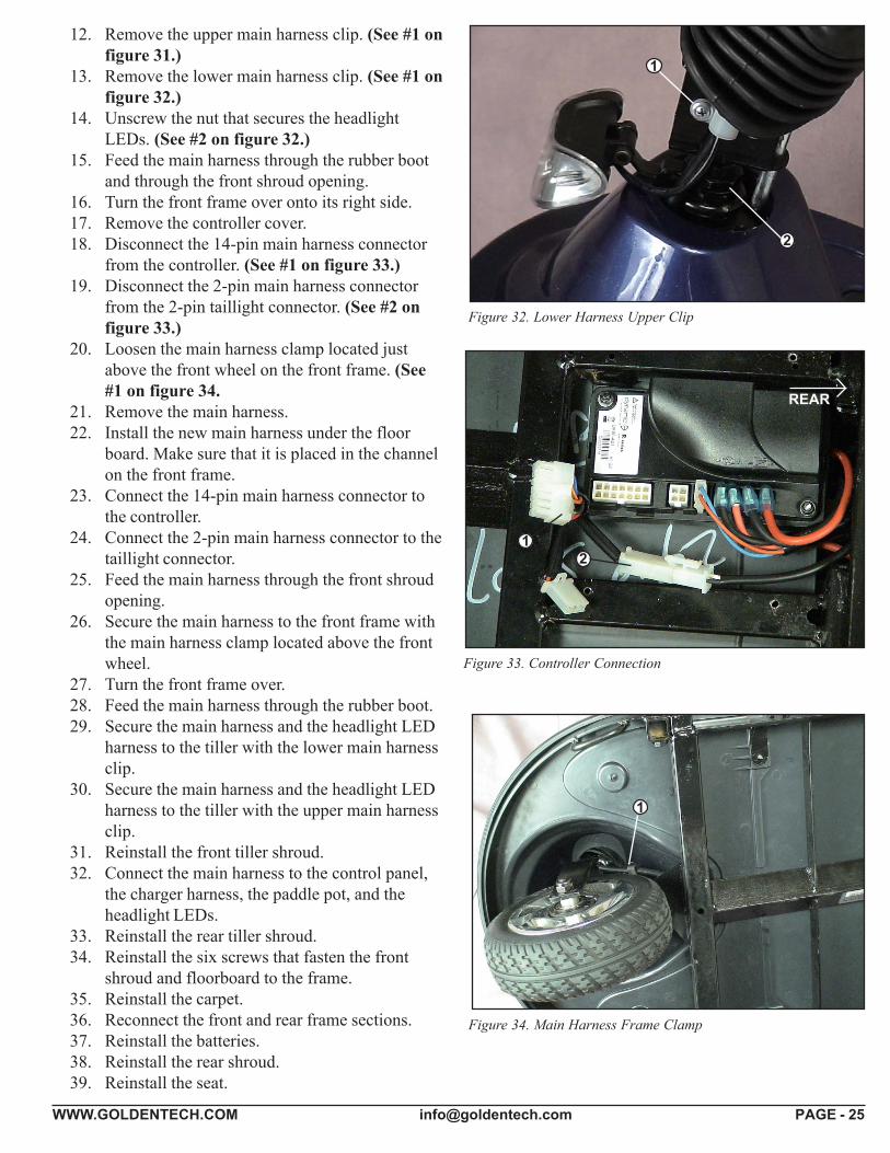
CHARGER HARNESS FUSE REPLACEMENT
1. Place the freewheel lever in the engaged position.2. Remove the eight(8) screws that fasten the back tiller
shroud to the tiller.3. Unplug the charger harness from the main harness.4. Open the fuse holder located on the red wire (See #1
on figure 29.)5. Remove the fuse.6. Install a new 10A fuse.
Plug the charger harness back into the main harness.7. Reinstall the back tiller shroud onto the tiller.
Figure 29. Charger Harness Fuse
1
1
Figure 30. Floorboard and Front Shroud
Figure 31. Main Harness Upper Clip
1
MAIN HARNESS REPLACEMENT (340)
Tools needed: Phillips screwdriver, adjustable wrench
1. Place the freewheel lever in the engaged position.2. Remove the key from the key switch.3. Remove the seat4. Remove the rear shroud.5. Remove the batteries.6. Separate the front and rear frames.7. Remove the eight (8) screws that fasten the back
shroud to the tiller.8. Disconnect the main harness from the control panel,
the charger harness, the paddle pot, and the headlightLEDs.
9. Remove the four (4) screws that fasten the front tillershroud and the basket bracket to the tiller.
10. Remove the carpet.11. Remove the six screws that fasten the floorboard and
front shroud to the front frame (See #1 on figure 30.)
WWW.GOLDENTECH.COM [email protected] PAGE - 25
12. Remove the upper main harness clip. (See #1 onfigure 31.)
13. Remove the lower main harness clip. (See #1 onfigure 32.)
14. Unscrew the nut that secures the headlightLEDs. (See #2 on figure 32.)
15. Feed the main harness through the rubber bootand through the front shroud opening.
16. Turn the front frame over onto its right side.17. Remove the controller cover.18. Disconnect the 14-pin main harness connector
from the controller. (See #1 on figure 33.)19. Disconnect the 2-pin main harness connector
from the 2-pin taillight connector. (See #2 onfigure 33.)
20. Loosen the main harness clamp located justabove the front wheel on the front frame. (See#1 on figure 34.
21. Remove the main harness.22. Install the new main harness under the floor
board. Make sure that it is placed in the channelon the front frame.
23. Connect the 14-pin main harness connector tothe controller.
24. Connect the 2-pin main harness connector to thetaillight connector.
25. Feed the main harness through the front shroudopening.
26. Secure the main harness to the front frame withthe main harness clamp located above the frontwheel.
27. Turn the front frame over.28. Feed the main harness through the rubber boot.29. Secure the main harness and the headlight LED
harness to the tiller with the lower main harnessclip.
30. Secure the main harness and the headlight LEDharness to the tiller with the upper main harnessclip.
31. Reinstall the front tiller shroud.32. Connect the main harness to the control panel,
the charger harness, the paddle pot, and theheadlight LEDs.
33. Reinstall the rear tiller shroud.34. Reinstall the six screws that fasten the front
shroud and floorboard to the frame.35. Reinstall the carpet.36. Reconnect the front and rear frame sections.37. Reinstall the batteries.38. Reinstall the rear shroud.39. Reinstall the seat.
Figure 32. Lower Harness Upper Clip
2
1
Figure 33. Controller Connection
12
1
Figure 34. Main Harness Frame Clamp
REAR

WWW.GOLDENTECH.COM [email protected] PAGE - 26
APPENDIX A - HOW TO USE A VOLTMETER
Step1Plug the probes into the meter. Red goes to the positive (+) and black to the negative (-).
Step2Turn the selector dial or switch to the type of measurement you want. To measure direct current - a battery, forexample - use DCV. To measure alternating current, such as a wall outlet, use ACV.
Step3Choose the range setting. The dial may have options from 5 to 1000 on the DCV side and 10 to 1000 on the ACVside. The setting should be the top end of the voltage you are reading. Not all voltmeters have this setting.
Step4Turn the meter on.
Step5Hold the probes by the insulated handles and touch the red probe to the positive side of a DC circuit or either side ofan AC circuit. Touch the other side with the black probe.
Step6Read the digital display or analog dial.
Figure 35. Multitester (Set to DC Volts)
WWW.GOLDENTECH.COM [email protected] PAGE - 27
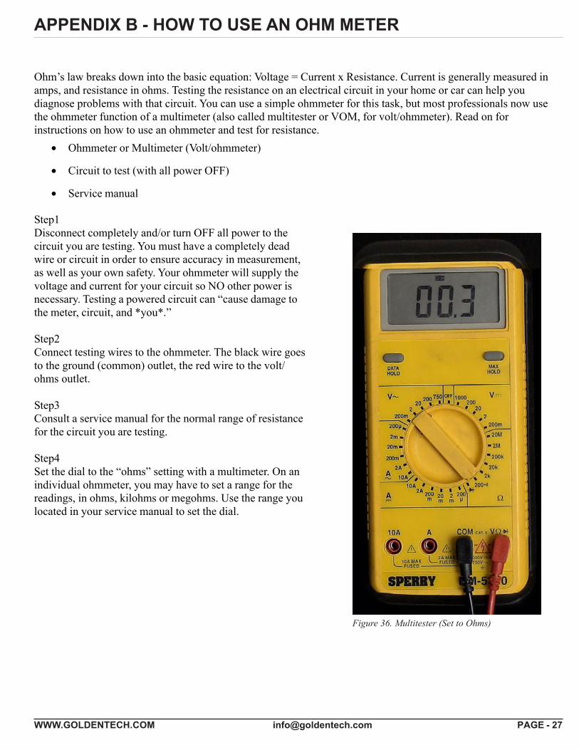
APPENDIX B - HOW TO USE AN OHM METER
Ohm’s law breaks down into the basic equation: Voltage = Current x Resistance. Current is generally measured inamps, and resistance in ohms. Testing the resistance on an electrical circuit in your home or car can help youdiagnose problems with that circuit. You can use a simple ohmmeter for this task, but most professionals now usethe ohmmeter function of a multimeter (also called multitester or VOM, for volt/ohmmeter). Read on forinstructions on how to use an ohmmeter and test for resistance.
• Ohmmeter or Multimeter (Volt/ohmmeter)
• Circuit to test (with all power OFF)
• Service manual
Step1Disconnect completely and/or turn OFF all power to thecircuit you are testing. You must have a completely deadwire or circuit in order to ensure accuracy in measurement,as well as your own safety. Your ohmmeter will supply thevoltage and current for your circuit so NO other power isnecessary. Testing a powered circuit can “cause damage tothe meter, circuit, and *you*.”
Step2Connect testing wires to the ohmmeter. The black wire goesto the ground (common) outlet, the red wire to the volt/ohms outlet.
Step3Consult a service manual for the normal range of resistancefor the circuit you are testing.
Step4Set the dial to the “ohms” setting with a multimeter. On anindividual ohmmeter, you may have to set a range for thereadings, in ohms, kilohms or megohms. Use the range youlocated in your service manual to set the dial.
Figure 36. Multitester (Set to Ohms)
WWW.GOLDENTECH.COM [email protected] PAGE - 28
APPENDIX C - WIRING DIAGRAM

Golden Technologies401 Bridge StreetOld Forge, PA 18518www.goldentech.com
Your L i fe In Mo t ion
GCX40SERVMAN_06/11/2013


![[Medicare FFS COMPANION GUIDE] Medicare Fee-For- … · [Medicare FFS COMPANION GUIDE] 1 [April 2017 005010] Medicare Fee-For-Service Standard Companion Guide Trading Partner Information](https://img.dokumen.tips/doc/110x75/5b15e5847f8b9a5e798bb94d/medicare-ffs-companion-guide-medicare-fee-for-medicare-ffs-companion-guide.jpg)


![IT Service Management[1].a Companion to ITIL](https://img.dokumen.tips/doc/110x75/552071c9497959842f8b4b67/it-service-management1a-companion-to-itil.jpg)