Embed Size (px)
Citation preview
GR-AXM300COMPACT VHS CAMCORDER
INSTRUCTIONS
LYT0040-001A
Compact VHS
For Customer Use:Enter below the Model No. and SerialNo. which is located on the bottom ofcabinet. Retain this information forfuture reference.
Model No.
Serial No.
2 EN
Dear Customer,Thank you for purchasing the JVC Compact VHScamcorder. Before use, please read the safetyinformation and precautions contained in thefollowing pages to ensure safe use of your newcamcorder.
Using This Instruction Manual• All major sections and subsections are listed in the
Table Of Contents (Z pg. 7).• Notes appear after most subsections. Be sure to read
these as well.• Basic and advanced features/operation are separated
for easier reference.It is recommended that you . . ...... refer to the Index (Z pgs. 55 – 58) and
familiarize yourself with button locations, etc.before use.
..... read thoroughly the Safety Precautions and SafetyInstructions that follow. They contain extremelyimportant information regarding the safe use ofyour new camcorder.
SAFETYPRECAUTIONS
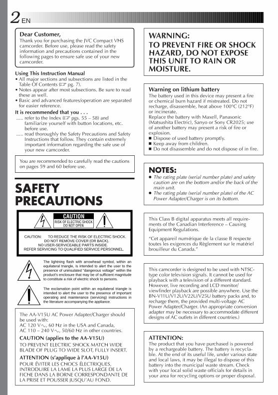
The AA-V15U AC Power Adapter/Charger shouldbe used with:AC 120 V`, 60 Hz in the USA and Canada,AC 110 – 240 V`, 50/60 Hz in other countries.
CAUTION (applies to the AA-V15U)TO PREVENT ELECTRIC SHOCK MATCH WIDEBLADE OF PLUG TO WIDE SLOT, FULLY INSERT.
ATTENTION (s’applique à l’AA-V15U)POUR ÉVITER LES CHOCS ÉLECTRIQUES,INTRODUIRE LA LAME LA PLUS LARGE DE LAFICHE DANS LA BORNE CORRESPONDANTE DELA PRISE ET POUSSER JUSQU’AU FOND.
CAUTIONRISK OF ELECTRIC SHOCK
DO NOT OPEN
CAUTION: TO REDUCE THE RISK OF ELECTRIC SHOCK. DO NOT REMOVE COVER (OR BACK).NO USER-SERVICEABLE PARTS INSIDE.
REFER SERVICING TO QUALIFIED SERVICE PERSONNEL.
The lightning flash with arrowhead symbol, within an equilateral triangle, is intended to alert the user to the presence of uninsulated "dangerous voltage" within the product's enclosure that may be of sufficient magnitude to constitute a risk of electric shock to persons.
The exclamation point within an equilateral triangle is intended to alert the user to the presence of important operating and maintenance (servicing) instructions in the literature accompanying the appliance.
WARNING:TO PREVENT FIRE OR SHOCKHAZARD, DO NOT EXPOSETHIS UNIT TO RAIN ORMOISTURE.
Warning on lithium batteryThe battery used in this device may present a fireor chemical burn hazard if mistreated. Do notrecharge, disassemble, heat above 100°C (212°F)or incinerate.Replace the battery with Maxell, Panasonic(Matsushita Electric), Sanyo or Sony CR2025; useof another battery may present a risk of fire orexplosion.n Dispose of used battery promptly.n Keep away from children.n Do not disassemble and do not dispose of in fire.
NOTES:● The rating plate (serial number plate) and safety
caution are on the bottom and/or the back of themain unit.
● The rating plate (serial number plate) of the ACPower Adapter/Charger is on its bottom.
This Class B digital apparatus meets all require-ments of the Canadian Interference – CausingEquipment Regulations.
“Cet appareil numérique de la classe B respectetoutes les exigences du Règlement sur le matérielbrouilleur du Canada.”
This camcorder is designed to be used with NTSC-type color television signals. It cannot be used forplayback with a television of a different standard.However, live recording and LCD monitor/viewfinder playback are possible anywhere. Use theBN-V11U/V12U/V22U/V25U battery packs and, torecharge them, the provided multi-voltage ACPower Adapter/Charger. (An appropriate conversionadapter may be necessary to accommodate differentdesigns of AC outlets in different countries.)
ATTENTION:The product that you have purchased is poweredby a rechargeable battery. The battery is recycla-ble. At the end of its useful life, under various stateand local laws, it may be illegal to dispose of thisbattery into the municipal waste stream. Checkwith your local solid waste officials for details inyour area for recycling options or proper disposal.
You are recommended to carefully read the cautionson pages 59 and 60 before use.

EN 35. VentilationSlots and openings in the cabinet are provided forventilation. To ensure reliable operation of the productand to protect it from overheating, these openings mustnot be blocked or covered.•Do not block the openings by placing the product on
a bed, sofa, rug or other similar surface.•Do not place the product in a built-in installation
such as a bookcase or rack unless proper ventilationis provided or the manufacturer’s instructions havebeen adhered to.
6. Wall or Ceiling MountingThe product should be mounted to a wall or ceilingonly as recommended by the manufacturer.
ANTENNA INSTALLATIONINSTRUCTIONS1. Outdoor Antenna GroundingIf an outside antenna or cable system is connected tothe product, be sure the antenna or cable system isgrounded so as to provide some protection againstvoltage surges and built-up static charges. Article 810of the National Electrical Code, ANSI/NFPA 70,provides information with regard to proper groundingof the mast and supporting structure, grounding of thelead-in wire to an antenna discharge unit, size ofgrounding conductors, location of antenna dischargeunit, connection to grounding electrodes, andrequirements for the grounding electrode.
2. LightningFor added protection for this product during a lightningstorm, or when it is left unattended and unused for longperiods of time, unplug it from the wall outlet anddisconnect the antenna or cable system. This willprevent damage to the product due to lightning andpower-line surges.
3. Power LinesAn outside antenna system should not be located in thevicinity of overhead power lines or other electric lightor power circuits, or where it can fall into such powerlines or circuits. When installing an outside antennasystem, extreme care should be taken to keep fromtouching such power lines or circuits as contact withthem might be fatal.
IMPORTANT PRODUCTSAFETY INSTRUCTIONSElectrical energy can perform many useful func-tions. But improper use can result in potentialelectrical shock or fire hazards. This product hasbeen engineered and manufactured to assure yourpersonal safety. In order not to defeat the built-insafeguards, observe the following basic rules for itsinstallation, use and servicing.
ATTENTION:Follow and obey all warnings and instructionsmarked on your product and its operating instruc-tions. For your safety, please read all the safety andoperating instructions before you operate thisproduct and keep this manual for future reference.
INSTALLATION1. Grounding or Polarization(A) Your product may be equipped with a polarized
alternating-current line plug (a plug having oneblade wider than the other). This plug will fit intothe power outlet only one way. This is a safetyfeature.If you are unable to insert the plug fully into theoutlet, try reversing the plug. If the plug should stillfail to fit, contact your electrician to replace yourobsolete outlet. Do not defeat the safety purpose ofthe polarized plug.
(B) Your product may be equipped with a 3-wiregrounding-type plug, a plug having a third(grounding) pin. This plug will only fit into agrounding-type power outlet. This is a safetyfeature.If you are unable to insert the plug into the outlet,contact your electrician to replace your obsoleteoutlet. Do not defeat the safety purpose of thegrounding-type plug.
2. Power SourcesOperate your product only from the type of powersource indicated on the marking label. If you are notsure of the type of power supply to your home, consultyour product dealer or local power company. If yourproduct is intended to operate from battery power, orother sources, refer to the operating instructions.
3. OverloadingDo not overload wall outlets, extension cords, orintegral convenience receptacles as this can result in arisk of fire or electric shock.
4. Power Cord ProtectionPower supply cords should be routed so that they arenot likely to be walked on or pinched by items placedupon or against them, paying particular attention tocords at plugs, convenience receptacles, and the pointwhere they exit from the product.
ANTENNALEAD IN WIRE
ANTENNADISCHARGE UNIT(NEC SECTION 810-20)
GROUNDING CONDUCTORS(NEC SECTION 810-21)
GROUND CLAMPS
POWER SERVICE GROUNDING ELECTRODE SYSTEM(NEC ART 250. PART H)
NEC – NATIONAL ELECTRICAL CODE
ELECTRIC SERVICEEQUIPMENT
EXAMPLE OF ANTENNA GROUNDING AS PERNATIONAL ELECTRICAL CODE, ANSI/NFPA 70
GROUND CLAMP
4 EN
USE1. AccessoriesTo avoid personal injury:• Do not place this product on an unstable cart,
stand, tripod, bracket or table. It may fall, causingserious injury to a child or adult, and seriousdamage to the product.
• Use only with a cart, stand, tripod, bracket, ortable recommended by the manufacturer or soldwith the product.
• Use a mounting accessory recommended by themanufacturer and follow the manufacturer’sinstructions for any mounting of the product.
• Do not try to roll a cart with small casters acrossthresholds or deep-pile carpets.
2. Product and Cart CombinationA product and cart combination should be movedwith care. Quick stops, excessive force, and unevensurfaces may cause the product and cart combina-tion to overturn.
3. Water and MoistureDo not use this productnear water—for example,near a bath tub, washbowl, kitchen sink orlaundry tub, in a wetbasement, or near aswimming pool and thelike.
4. Object and Liquid EntryNever push objects of any kind into this productthrough openings as they may touch dangerousvoltage points or short-out parts that could result ina fire or electric shock. Never spill liquid of anykind on the product.
5. AttachmentsDo not use attachments not recommended by themanufacturer of this product as they may causehazards.
6. CleaningUnplug this product from the wall outlet beforecleaning. Do not use liquid cleaners or aerosolcleaners. Use a damp cloth for cleaning.
7. HeatThe product should be situated away from heatsources such as radiators, heat registers, stoves, orother products (including amplifiers) that produceheat.
SERVICING1. ServicingIf your product is not operating correctly or exhibitsa marked change in performance and you areunable to restore normal operation by following thedetailed procedure in its operating instructions, donot attempt to service it yourself as opening orremoving covers may expose you to dangerousvoltage or other hazards. Refer all servicing toqualified service personnel.
2. Damage Requiring ServiceUnplug this product from the wall outlet and referservicing to qualified service personnel under thefollowing conditions:a. When the power supply cord or plug is damaged.b. If liquid has been spilled, or objects have fallen
into the product.c. If the product has been exposed to rain or water.d. If the product does not operate normally by
following the operating instructions. Adjust onlythose controls that are covered by the operatinginstructions as an improper adjustment of othercontrols may result in damage and will oftenrequire extensive work by a qualified technicianto restore the product to its normal operation.
e. If the product has been dropped or damaged inany way.
f. When the product exhibits a distinct change inperformance—this indicates a need for service.
3. Replacement PartsWhen replacement parts are required, be sure theservice technician has used replacement partsspecified by the manufacturer or have the samecharacteristics as the original part. Unauthorizedsubstitutions may result in fire, electric shock orother hazards.
4. Safety CheckUpon completion of any service or repairs to thisproduct, ask the service technician to perform safetychecks to determine that the product is in safeoperating condition.
PORTABLE CART WARNING(Symbol provided by RETAC)
EN 5
21
3
342
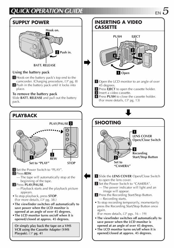
1Using the battery pack1 Hook-on the battery pack’s top end to the
camcorder. (Charging procedure, Z pg. 8)2 Push in the battery pack until it locks into
place.
To remove the battery packSlide BATT. RELEASE and pull out the batterypack.
QUICK OPERATION GUIDE
1 Set the Power Switch to “PLAY”.2 Press REW.
— The tape will automatically stop at thebeginning of the tape.
3 Press PLAY/PAUSE.— Playback starts and the playback picture
appears.•To stop playback, press STOP.
(For more details, Z pg. 38.)•The viewfinder switches off automatically to
save power when the LCD monitor isopened at an angle of over 45 degrees.
•The LCD monitor turns on/off when it isopened/closed at approx. 45 degrees.
Or simply play back the tape on a VHSVCR using the Cassette Adapter (VHSPlaypak). Z pg. 41
1 Slide the LENS COVER Open/Close Switchto open the lens cover.
2 Set the Power Switch to “CAMERA”.— The power indicator will light and an
image will appear.3 Press the Recording Start/Stop Button.
— Recording starts.• To stop recording temporarily, momentarily
press the Recording Start/Stop Button onceagain.(For more details, Z pgs. 16 – 19)
• The viewfinder switches off automatically tosave power when the LCD monitor isopened at an angle of over 45 degrees.
• The LCD monitor turns on/off when it isopened/closed at approx. 45 degrees.
SUPPLY POWER INSERTING A VIDEOCASSETTE
PLAYBACKSHOOTING
1 Open the LCD monitor to an angle of over45 degrees.
2 Press EJECT to open the cassette holder.3 Insert a video cassette.4 Press PUSH to close the cassette holder.
(For more details, Z pg. 13)
2
1
BATT. RELEASE
3
2
1
Hook on.
PLAY/PAUSE
STOP
Push in.
RecordingStart/Stop Button
Set to“CAMERA”
Set to “PLAY”REW
EJECTPUSH
Open
LENS COVEROpen/Close Switch
6 EN MAJOR FEATURES
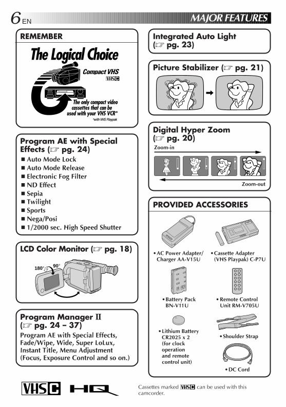
REMEMBER
Program AE with SpecialEffects (Z pg. 24)n Auto Mode Lockn Auto Mode Releasen Electronic Fog Filtern ND Effectn Sepian Twilightn Sportsn Nega/Posin 1/2000 sec. High Speed Shutter
Cassettes marked can be used with thiscamcorder.
Digital Hyper Zoom(Z pg. 20)
Picture Stabilizer (Z pg. 21)
Integrated Auto Light(Z pg. 23)
The Logical Choice
The only compact videocassettes that can be
used with your VHS VCR*
LCD Color Monitor (Z pg. 18)
180° 90°
Program Manager II(Z pg. 24 – 37)Program AE with Special Effects,Fade/Wipe, Wide, Super LoLux,Instant Title, Menu Adjustment(Focus, Exposure Control and so on.)
PROVIDED ACCESSORIES
•AC Power Adapter/Charger AA-V15U
•Cassette Adapter(VHS Playpak) C-P7U
•Shoulder Strap
•Battery PackBN-V11U
•DC Cord
• Remote ControlUnit RM-V705U
•Lithium BatteryCR2025 x 2(for clockoperationand remotecontrol unit)
Zoom-in
Zoom-out
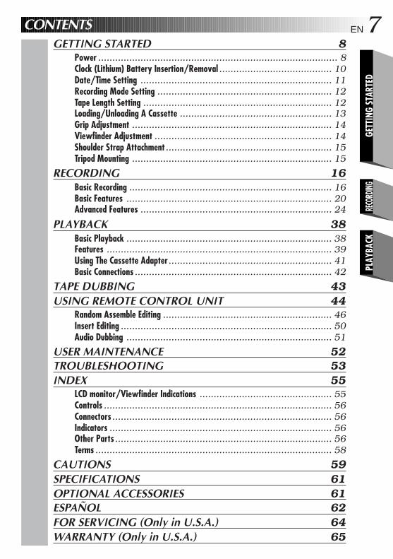
EN 7CONTENTSGETTING STARTED 8
Power ..................................................................................... 8Clock (Lithium) Battery Insertion/Removal ........................................ 10Date/Time Setting .................................................................... 11Recording Mode Setting .............................................................. 12Tape Length Setting ................................................................... 12Loading/Unloading A Cassette ...................................................... 13Grip Adjustment ....................................................................... 14Viewfinder Adjustment ............................................................... 14Shoulder Strap Attachment........................................................... 15Tripod Mounting ....................................................................... 15
RECORDING 16Basic Recording ........................................................................ 16Basic Features ......................................................................... 20Advanced Features .................................................................... 24
PLAYBACK 38Basic Playback ......................................................................... 38Features ................................................................................ 39Using The Cassette Adapter.......................................................... 41Basic Connections ...................................................................... 42
TAPE DUBBING 43USING REMOTE CONTROL UNIT 44
Random Assemble Editing ............................................................ 46Insert Editing ........................................................................... 50Audio Dubbing ......................................................................... 51
USER MAINTENANCE 52TROUBLESHOOTING 53INDEX 55
LCD monitor/Viewfinder Indications ............................................... 55Controls ................................................................................. 56Connectors .............................................................................. 56Indicators ............................................................................... 56Other Parts ............................................................................. 56Terms .................................................................................... 58
CAUTIONS 59SPECIFICATIONS 61OPTIONAL ACCESSORIES 61ESPAÑOL 62FOR SERVICING (Only in U.S.A.) 64WARRANTY (Only in U.S.A.) 65
GETT
ING
STAR
TED
RECO
RDING
PLAY
BACK
8 EN GETTING STARTED
11
2
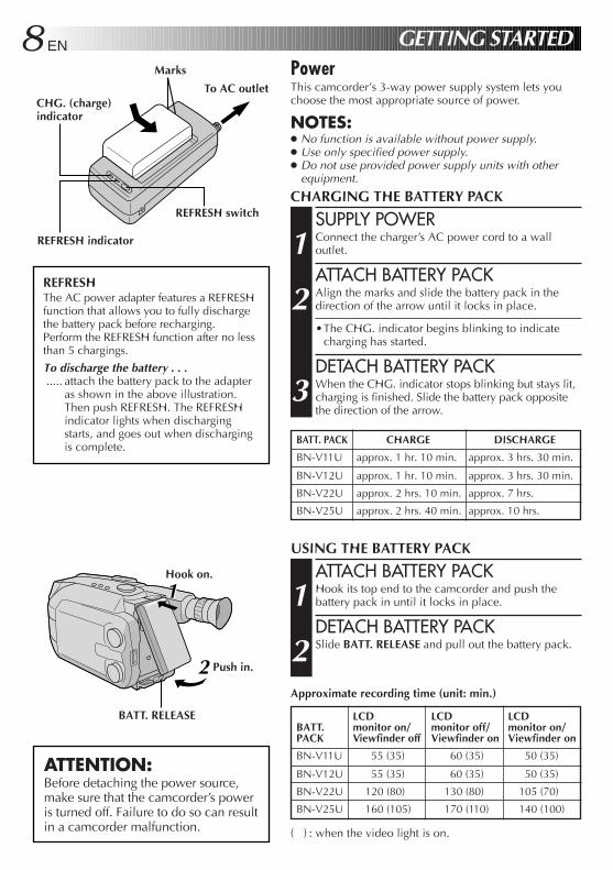
PowerThis camcorder’s 3-way power supply system lets youchoose the most appropriate source of power.
NOTES:● No function is available without power supply.● Use only specified power supply.● Do not use provided power supply units with other
equipment.
CHARGING THE BATTERY PACK
SUPPLY POWER
1 Connect the charger’s AC power cord to a walloutlet.
ATTACH BATTERY PACK
2 Align the marks and slide the battery pack in thedirection of the arrow until it locks in place.
•The CHG. indicator begins blinking to indicatecharging has started.
DETACH BATTERY PACK
3 When the CHG. indicator stops blinking but stays lit,charging is finished. Slide the battery pack oppositethe direction of the arrow.
USING THE BATTERY PACK
ATTACH BATTERY PACK
1 Hook its top end to the camcorder and push thebattery pack in until it locks in place.
DETACH BATTERY PACK
2 Slide BATT. RELEASE and pull out the battery pack.
ATTENTION:Before detaching the power source,make sure that the camcorder’s poweris turned off. Failure to do so can resultin a camcorder malfunction.
REFRESHThe AC power adapter features a REFRESHfunction that allows you to fully dischargethe battery pack before recharging.Perform the REFRESH function after no lessthan 5 chargings.
To discharge the battery . . ...... attach the battery pack to the adapter
as shown in the above illustration.Then push REFRESH. The REFRESHindicator lights when dischargingstarts, and goes out when dischargingis complete.
CHG. (charge)indicator
Marks
To AC outlet
Hook on.
Push in.
BATT. RELEASE
REFRESH indicator
REFRESH switch
Approximate recording time (unit: min.)
BATT. PACK CHARGE DISCHARGE
BN-V11U approx. 1 hr. 10 min. approx. 3 hrs. 30 min.
BN-V12U approx. 1 hr. 10 min. approx. 3 hrs. 30 min.
BN-V22U approx. 2 hrs. 10 min. approx. 7 hrs.
BN-V25U approx. 2 hrs. 40 min. approx. 10 hrs.
LCD LCD LCDBATT. monitor on/ monitor off/ monitor on/PACK Viewfinder off Viewfinder on Viewfinder on
BN-V11U 55 (35) 60 (35) 50 (35)
BN-V12U 55 (35) 60 (35) 50 (35)
BN-V22U 120 (80) 130 (80) 105 (70)
BN-V25U 160 (105) 170 (110) 140 (100)
( ) : when the video light is on.
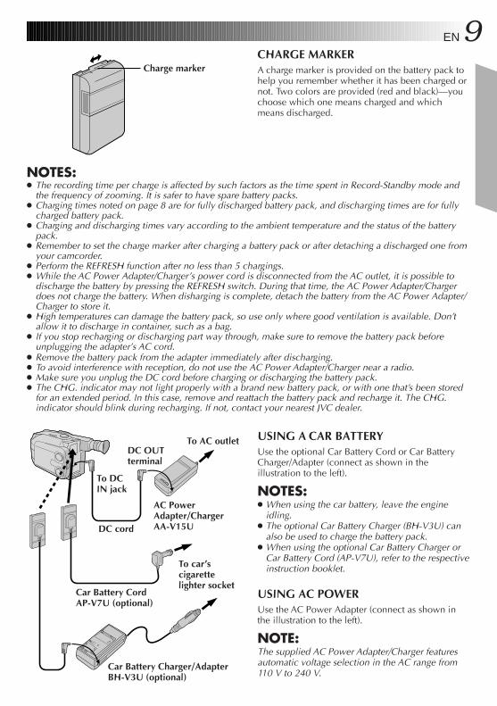
EN 9CHARGE MARKERA charge marker is provided on the battery pack tohelp you remember whether it has been charged ornot. Two colors are provided (red and black)—youchoose which one means charged and whichmeans discharged.
NOTES:● The recording time per charge is affected by such factors as the time spent in Record-Standby mode and
the frequency of zooming. It is safer to have spare battery packs.● Charging times noted on page 8 are for fully discharged battery pack, and discharging times are for fully
charged battery pack.● Charging and discharging times vary according to the ambient temperature and the status of the battery
pack.● Remember to set the charge marker after charging a battery pack or after detaching a discharged one from
your camcorder.● Perform the REFRESH function after no less than 5 chargings.● While the AC Power Adapter/Charger’s power cord is disconnected from the AC outlet, it is possible to
discharge the battery by pressing the REFRESH switch. During that time, the AC Power Adapter/Chargerdoes not charge the battery. When disharging is complete, detach the battery from the AC Power Adapter/Charger to store it.
● High temperatures can damage the battery pack, so use only where good ventilation is available. Don’tallow it to discharge in container, such as a bag.
● If you stop recharging or discharging part way through, make sure to remove the battery pack beforeunplugging the adapter’s AC cord.
● Remove the battery pack from the adapter immediately after discharging.● To avoid interference with reception, do not use the AC Power Adapter/Charger near a radio.● Make sure you unplug the DC cord before charging or discharging the battery pack.● The CHG. indicator may not light properly with a brand new battery pack, or with one that’s been stored
for an extended period. In this case, remove and reattach the battery pack and recharge it. The CHG.indicator should blink during recharging. If not, contact your nearest JVC dealer.
USING A CAR BATTERYUse the optional Car Battery Cord or Car BatteryCharger/Adapter (connect as shown in theillustration to the left).
NOTES:● When using the car battery, leave the engine
idling.● The optional Car Battery Charger (BH-V3U) can
also be used to charge the battery pack.● When using the optional Car Battery Charger or
Car Battery Cord (AP-V7U), refer to the respectiveinstruction booklet.
USING AC POWERUse the AC Power Adapter (connect as shown inthe illustration to the left).
NOTE:The supplied AC Power Adapter/Charger featuresautomatic voltage selection in the AC range from110 V to 240 V.
To DCIN jack
DC OUTterminal
To AC outlet
AC PowerAdapter/ChargerAA-V15UDC cord
To car’scigarettelighter socket
Car Battery CordAP-V7U (optional)
Charge marker
Car Battery Charger/AdapterBH-V3U (optional)
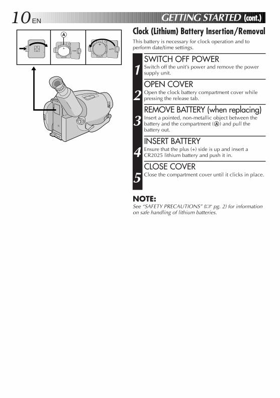
10 EN GETTING STARTED (cont.)Clock (Lithium) Battery Insertion/RemovalThis battery is necessary for clock operation and toperform date/time settings.
SWITCH OFF POWER
1 Switch off the unit’s power and remove the powersupply unit.
OPEN COVER
2 Open the clock battery compartment cover whilepressing the release tab.
REMOVE BATTERY (when replacing)
3 Insert a pointed, non-metallic object between thebattery and the compartment ( A ) and pull thebattery out.
INSERT BATTERY
4 Ensure that the plus (+) side is up and insert aCR2025 lithium battery and push it in.
CLOSE COVER
5 Close the compartment cover until it clicks in place.
NOTE:See “SAFETY PRECAUTIONS” (Z pg. 2) for informationon safe handling of lithium batteries.
A
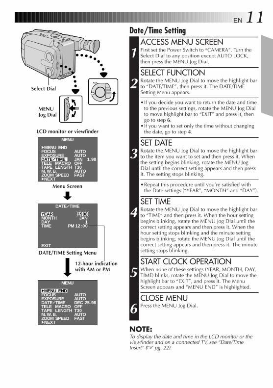
EN 11Date/Time Setting
ACCESS MENU SCREEN
1 First set the Power Switch to “CAMERA”. Turn theSelect Dial to any position except AUTO LOCK,then press the MENU Jog Dial.
SELECT FUNCTION
2 Rotate the MENU Jog Dial to move the highlight barto “DATE/TIME”, then press it. The DATE/TIMESetting Menu appears.
•If you decide you want to return the date and timeto the previous settings, rotate the MENU Jog Dialto move highlight bar to “EXIT” and press it, thengo to step 6.
•If you want to set only the time without changingthe date, go to step 4.
SET DATE
3 Rotate the MENU Jog Dial to move the highlight barto the item you want to set and then press it. Whenthe setting begins blinking, rotate the MENU JogDial until the correct setting appears and then pressit. The setting stops blinking.
•Repeat this procedure until you’re satisfied withthe Date settings (“YEAR”, “MONTH” and “DAY”).
SET TIME
4 Rotate the MENU Jog Dial to move the highlight barto “TIME” and then press it. When the hour settingbegins blinking, rotate the MENU Jog Dial until thecorrect setting appears and then press it. When thehour setting stops blinking and the minute settingbegins blinking, rotate the MENU Jog Dial until thecorrect setting appears and then press it. The minutesetting stops blinking.
START CLOCK OPERATION
5 When none of these settings (YEAR, MONTH, DAY,TIME) blinks, rotate the MENU Jog Dial to move thehighlight bar to “EXIT”, and press it. The MenuScreen appears and “MENU END” is highlighted.
CLOSE MENU
6 Press the MENU Jog Dial.
NOTE:To display the date and time in the LCD monitor or theviewfinder and on a connected TV, see “Date/TimeInsert” (Z pg. 22).
MENU
4MENU ENDFOCUSEXPOSUREDATE TIMETELE MACROTAPE LENGTHM. W. B.ZOOM SPEED4NEXT
MENU
4MENU ENDFOCUSEXPOSUREDATE TIMETELE MACROTAPE LENGTHM. W. B.ZOOM SPEED4NEXT
DATE TIME
YEARMONTHDAYTIME
EXIT
1998JAN
1PM 12:00
AUTOAUTODECOFFT30AUTOFAST
25.98
AUTOAUTOJANOFFT30AUTOFAST
1.98
Menu Screen
DATE/TIME Setting Menu
LCD monitor or viewfinder
12-hour indicationwith AM or PM
MENUJog Dial
Select Dial
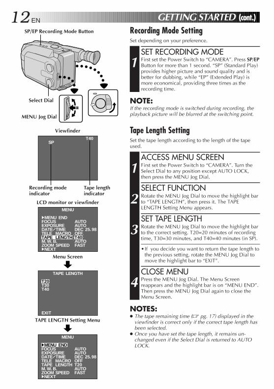
12 EN GETTING STARTED (cont.)Recording Mode SettingSet depending on your preference.
SET RECORDING MODE
1 First set the Power Switch to “CAMERA”. Press SP/EPButton for more than 1 second. “SP” (Standard Play)provides higher picture and sound quality and isbetter for dubbing, while “EP” (Extended Play) ismore economical, providing three times as therecording time.
NOTE:If the recording mode is switched during recording, theplayback picture will be blurred at the switching point.
Tape Length SettingSet the tape length according to the length of the tapeused.
ACCESS MENU SCREEN
1 First set the Power Switch to “CAMERA”. Turn theSelect Dial to any position except AUTO LOCK,then press the MENU Jog Dial.
SELECT FUNCTION
2 Rotate the MENU Jog Dial to move the highlight barto “TAPE LENGTH”, then press it. The TAPELENGTH Setting Menu appears.
SET TAPE LENGTH
3 Rotate the MENU Jog Dial to move the highlight barto the correct setting. T20=20 minutes of recordingtime, T30=30 minutes, and T40=40 minutes (in SP).
•If you decide you want to return the tape length tothe previous setting, rotate the MENU Jog Dial tomove the highlight bar to “EXIT”.
CLOSE MENU
4 Press the MENU Jog Dial. The Menu Screenreappears and the highlight bar is on “MENU END”.Then press the MENU Jog Dial again to close theMenu Screen.
NOTES:● The tape remaining time (Z pg. 17) displayed in the
viewfinder is correct only if the correct tape length hasbeen selected.
● Once you have set the tape length, it remains un-changed even if the Select Dial is returned to AUTOLOCK.
MENU
4MENU ENDFOCUSEXPOSUREDATE TIMETELE MACROTAPE LENGTHM. W. B.ZOOM SPEED4NEXT
AUTOAUTODECOFFT40AUTOFAST
25.98
MENU
4MENU ENDFOCUSEXPOSUREDATE TIMETELE MACROTAPE LENGTHM. W. B.ZOOM SPEED4NEXT
AUTOAUTODECOFFT20AUTOFAST
25.98
SPT40
T20T30T40
EXIT
TAPE LENGTH
SP/EP Recording Mode Button
Viewfinder
LCD monitor or viewfinder
Tape lengthindicator
Recording modeindicator
Menu Screen
TAPE LENGTH Setting Menu
Select Dial
MENU Jog Dial
EN 13
1
223344
5
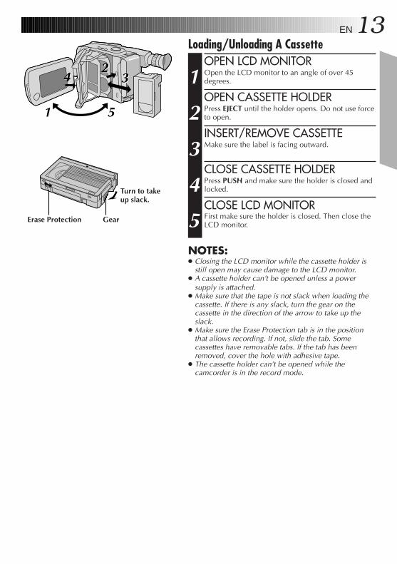
Loading/Unloading A CassetteOPEN LCD MONITOR
1 Open the LCD monitor to an angle of over 45degrees.
OPEN CASSETTE HOLDER
2 Press EJECT until the holder opens. Do not use forceto open.
INSERT/REMOVE CASSETTE
3 Make sure the label is facing outward.
CLOSE CASSETTE HOLDER
4 Press PUSH and make sure the holder is closed andlocked.
CLOSE LCD MONITOR
5 First make sure the holder is closed. Then close theLCD monitor.
NOTES:● Closing the LCD monitor while the cassette holder is
still open may cause damage to the LCD monitor.● A cassette holder can’t be opened unless a power
supply is attached.● Make sure that the tape is not slack when loading the
cassette. If there is any slack, turn the gear on thecassette in the direction of the arrow to take up theslack.
● Make sure the Erase Protection tab is in the positionthat allows recording. If not, slide the tab. Somecassettes have removable tabs. If the tab has beenremoved, cover the hole with adhesive tape.
● The cassette holder can’t be opened while thecamcorder is in the record mode.
Erase Protection Gear
Turn to takeup slack.
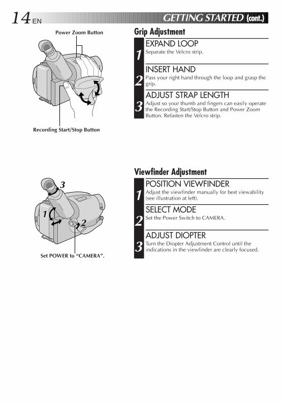
14 EN GETTING STARTED (cont.)Grip Adjustment
EXPAND LOOP
1 Separate the Velcro strip.
INSERT HAND
2 Pass your right hand through the loop and grasp thegrip.
ADJUST STRAP LENGTH
3 Adjust so your thumb and fingers can easily operatethe Recording Start/Stop Button and Power ZoomButton. Refasten the Velcro strip.
Viewfinder AdjustmentPOSITION VIEWFINDER
1 Adjust the viewfinder manually for best viewability(see illustration at left).
SELECT MODE
2 Set the Power Switch to CAMERA.
ADJUST DIOPTER
3 Turn the Diopter Adjustment Control until theindications in the viewfinder are clearly focused.
Power Zoom Button
1122
3
Recording Start/Stop Button
Set POWER to “CAMERA”.
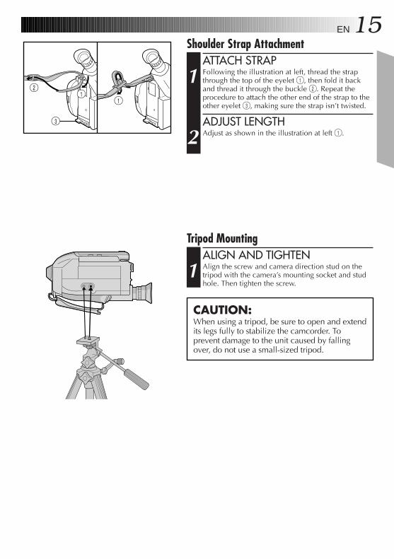
EN 15Shoulder Strap Attachment
ATTACH STRAP
1 Following the illustration at left, thread the strapthrough the top of the eyelet 1, then fold it backand thread it through the buckle 2. Repeat theprocedure to attach the other end of the strap to theother eyelet 3, making sure the strap isn’t twisted.
ADJUST LENGTH
2 Adjust as shown in the illustration at left 1.
CAUTION:When using a tripod, be sure to open and extendits legs fully to stabilize the camcorder. Toprevent damage to the unit caused by fallingover, do not use a small-sized tripod.
2
3
11
Tripod MountingALIGN AND TIGHTEN
1 Align the screw and camera direction stud on thetripod with the camera’s mounting socket and studhole. Then tighten the screw.
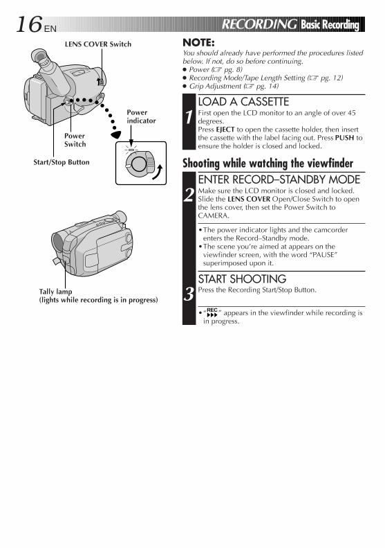
16 EN RECORDING Basic RecordingNOTE:You should already have performed the procedures listedbelow. If not, do so before continuing.● Power (Z pg. 8)● Recording Mode/Tape Length Setting (Z pg. 12)● Grip Adjustment (Z pg. 14)
LOAD A CASSETTE
1 First open the LCD monitor to an angle of over 45degrees.Press EJECT to open the cassette holder, then insertthe cassette with the label facing out. Press PUSH toensure the holder is closed and locked.
Shooting while watching the viewfinderENTER RECORD–STANDBY MODE
2 Make sure the LCD monitor is closed and locked.Slide the LENS COVER Open/Close Switch to openthe lens cover, then set the Power Switch toCAMERA.
•The power indicator lights and the camcorderenters the Record–Standby mode.
•The scene you’re aimed at appears on theviewfinder screen, with the word “PAUSE”superimposed upon it.
START SHOOTING
3 Press the Recording Start/Stop Button.
•“REC” appears in the viewfinder while recording isin progress.
LENS COVER Switch
Powerindicator
PowerSwitch
Start/Stop Button
Tally lamp(lights while recording is in progress)
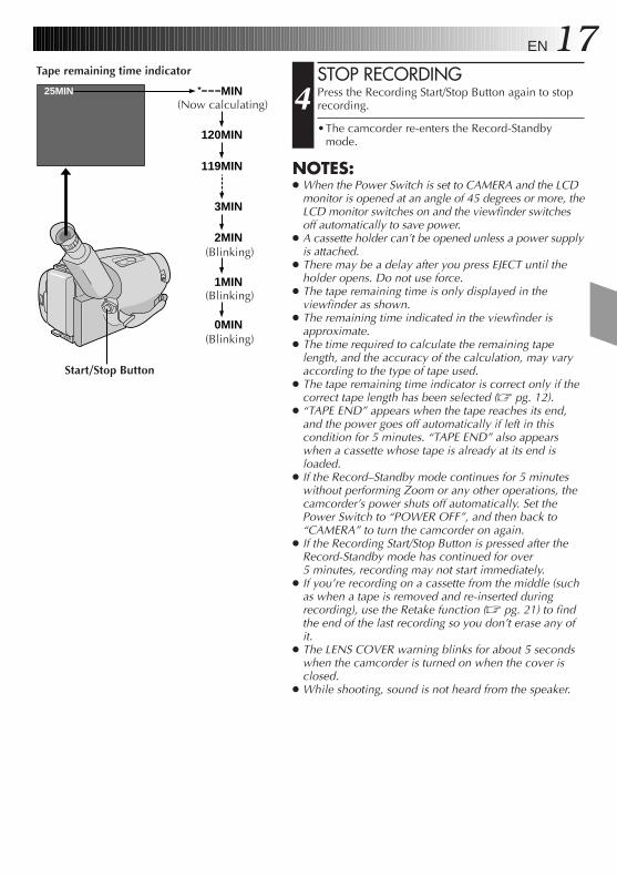
EN 17STOP RECORDING
4 Press the Recording Start/Stop Button again to stoprecording.
•The camcorder re-enters the Record-Standbymode.
NOTES:● When the Power Switch is set to CAMERA and the LCD
monitor is opened at an angle of 45 degrees or more, theLCD monitor switches on and the viewfinder switchesoff automatically to save power.
● A cassette holder can’t be opened unless a power supplyis attached.
● There may be a delay after you press EJECT until theholder opens. Do not use force.
● The tape remaining time is only displayed in theviewfinder as shown.
● The remaining time indicated in the viewfinder isapproximate.
● The time required to calculate the remaining tapelength, and the accuracy of the calculation, may varyaccording to the type of tape used.
● The tape remaining time indicator is correct only if thecorrect tape length has been selected (Z pg. 12).
● “TAPE END” appears when the tape reaches its end,and the power goes off automatically if left in thiscondition for 5 minutes. “TAPE END” also appearswhen a cassette whose tape is already at its end isloaded.
● If the Record–Standby mode continues for 5 minuteswithout performing Zoom or any other operations, thecamcorder’s power shuts off automatically. Set thePower Switch to “POWER OFF”, and then back to“CAMERA” to turn the camcorder on again.
● If the Recording Start/Stop Button is pressed after theRecord-Standby mode has continued for over5 minutes, recording may not start immediately.
● If you’re recording on a cassette from the middle (suchas when a tape is removed and re-inserted duringrecording), use the Retake function (Z pg. 21) to findthe end of the last recording so you don’t erase any ofit.
● The LENS COVER warning blinks for about 5 secondswhen the camcorder is turned on when the cover isclosed.
● While shooting, sound is not heard from the speaker.
25MIN
120MIN
119MIN
3MIN
2MIN
1MIN
0MIN
MIN
Tape remaining time indicator
(Now calculating)
(Blinking)
(Blinking)
(Blinking)
Start/Stop Button
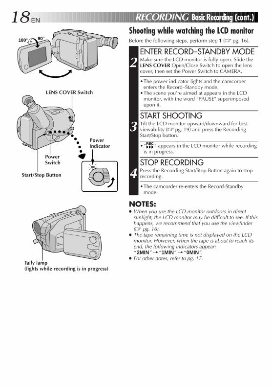
18 EN RECORDING Basic Recording (cont.)
Shooting while watching the LCD monitorBefore the following steps, perform step 1 (Z pg. 16).
ENTER RECORD–STANDBY MODE
2 Make sure the LCD monitor is fully open. Slide theLENS COVER Open/Close Switch to open the lenscover, then set the Power Switch to CAMERA.
•The power indicator lights and the camcorderenters the Record–Standby mode.
•The scene you’re aimed at appears in the LCDmonitor, with the word “PAUSE” superimposedupon it.
START SHOOTING
3 Tilt the LCD monitor upward/downward for bestviewability (Z pg. 19) and press the RecordingStart/Stop button.
•“REC” appears in the LCD monitor while recordingis in progress.
STOP RECORDING
4 Press the Recording Start/Stop Button again to stoprecording.
•The camcorder re-enters the Record-Standbymode.
NOTES:● When you use the LCD monitor outdoors in direct
sunlight, the LCD monitor may be difficult to see. If thishappens, we recommend that you use the viewfinder(Z pg. 16).
● The tape remaining time is not displayed on the LCDmonitor. However, when the tape is about to reach itsend, the following indicators appear:“ 2MIN” ¥“1MIN” ¥“ 0MIN”.
● For other notes, refer to pg. 17.
180° 90°
LENS COVER Switch
PowerSwitch
Start/Stop Button
Powerindicator
Tally lamp(lights while recording is in progress)
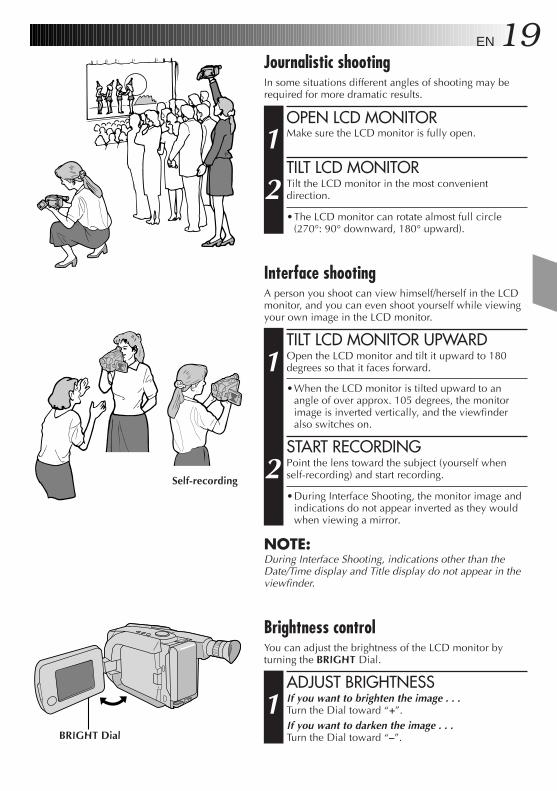
EN 19Journalistic shootingIn some situations different angles of shooting may berequired for more dramatic results.
OPEN LCD MONITOR
1 Make sure the LCD monitor is fully open.
TILT LCD MONITOR
2 Tilt the LCD monitor in the most convenientdirection.
•The LCD monitor can rotate almost full circle(270°: 90° downward, 180° upward).
Brightness controlYou can adjust the brightness of the LCD monitor byturning the BRIGHT Dial.
ADJUST BRIGHTNESS
1 If you want to brighten the image . . .Turn the Dial toward “+”.If you want to darken the image . . .Turn the Dial toward “–”.
Interface shootingA person you shoot can view himself/herself in the LCDmonitor, and you can even shoot yourself while viewingyour own image in the LCD monitor.
TILT LCD MONITOR UPWARD
1 Open the LCD monitor and tilt it upward to 180degrees so that it faces forward.
•When the LCD monitor is tilted upward to anangle of over approx. 105 degrees, the monitorimage is inverted vertically, and the viewfinderalso switches on.
START RECORDING
2 Point the lens toward the subject (yourself whenself-recording) and start recording.
•During Interface Shooting, the monitor image andindications do not appear inverted as they wouldwhen viewing a mirror.
NOTE:During Interface Shooting, indications other than theDate/Time display and Title display do not appear in theviewfinder.
BRIGHT Dial
Self-recording
20 EN
MENU
4MENU ENDFOCUSEXPOSUREDATE TIMETELE MACROTAPE LENGTHM. W. B.ZOOM SPEED4NEXT
AUTOAUTOJANOFFT30AUTOFAST
1.98
ZOOM SPEED
FASTSLOW
EXIT
RECORDING Basic Features
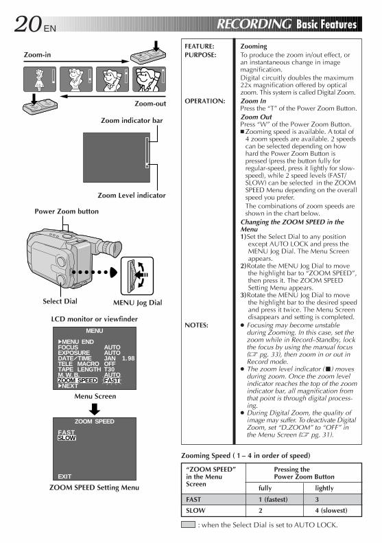
FEATURE: ZoomingPURPOSE: To produce the zoom in/out effect, or
an instantaneous change in imagemagnification.Digital circuitly doubles the maximum22x magnification offered by opticalzoom. This system is called Digital Zoom.
OPERATION: Zoom InPress the “T” of the Power Zoom Button.Zoom OutPress “W” of the Power Zoom Button.n Zooming speed is available. A total of
4 zoom speeds are available. 2 speedscan be selected depending on howhard the Power Zoom Button ispressed (press the button fully forregular-speed, press it lightly for slow-speed), while 2 speed levels (FAST/SLOW) can be selected in the ZOOMSPEED Menu depending on the overallspeed you prefer.The combinations of zoom speeds areshown in the chart below.
Changing the ZOOM SPEED in theMenu1)Set the Select Dial to any position
except AUTO LOCK and press theMENU Jog Dial. The Menu Screenappears.
2)Rotate the MENU Jog Dial to movethe highlight bar to “ZOOM SPEED”,then press it. The ZOOM SPEEDSetting Menu appears.
3)Rotate the MENU Jog Dial to movethe highlight bar to the desired speedand press it twice. The Menu Screendisappears and setting is completed.
NOTES: ● Focusing may become unstableduring Zooming. In this case, set thezoom while in Record–Standby, lockthe focus by using the manual focus(Z pg. 33), then zoom in or out inRecord mode.
● The zoom level indicator (5) movesduring zoom. Once the zoom levelindicator reaches the top of the zoomindicator bar, all magnification fromthat point is through digital process-ing.
● During Digital Zoom, the quality ofimage may suffer. To deactivate DigitalZoom, set “D.ZOOM” to “OFF” inthe Menu Screen (Z pg. 31).
Zoom-in
: when the Select Dial is set to AUTO LOCK.
Zooming Speed ( 1 – 4 in order of speed)
“ZOOM SPEED”in the MenuScreen
Pressing thePower Zoom Button
fully lightly
FAST 1 (fastest) 3
SLOW 2 4 (slowest)
Zoom-out
Zoom indicator bar
Zoom Level indicator
LCD monitor or viewfinder
ZOOM SPEED Setting Menu
MENU Jog Dial
Power Zoom button
Select Dial
Menu Screen
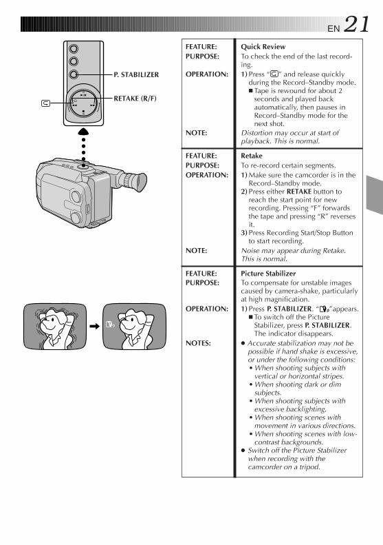
EN 21FEATURE: Quick ReviewPURPOSE: To check the end of the last record-
ing.OPERATION: 1) Press “ ” and release quickly
during the Record–Standby mode.n Tape is rewound for about 2
seconds and played backautomatically, then pauses inRecord–Standby mode for thenext shot.
NOTE: Distortion may occur at start ofplayback. This is normal.
FEATURE: RetakePURPOSE: To re-record certain segments.OPERATION: 1) Make sure the camcorder is in the
Record–Standby mode.2) Press either RETAKE button to
reach the start point for newrecording. Pressing “F” forwardsthe tape and pressing “R” reversesit.
3) Press Recording Start/Stop Buttonto start recording.
NOTE: Noise may appear during Retake.This is normal.
FEATURE: Picture StabilizerPURPOSE: To compensate for unstable images
caused by camera-shake, particularlyat high magnification.
OPERATION: 1) Press P. STABILIZER. “ ”appears.n To switch off the Picture
Stabilizer, press P. STABILIZER.The indicator disappears.
NOTES: ● Accurate stabilization may not bepossible if hand shake is excessive,or under the following conditions:• When shooting subjects with
vertical or horizontal stripes.• When shooting dark or dim
subjects.• When shooting subjects with
excessive backlighting.• When shooting scenes with
movement in various directions.• When shooting scenes with low-
contrast backgrounds.● Switch off the Picture Stabilizer
when recording with thecamcorder on a tripod.
P. STABILIZER
RETAKE (R/F)
22 EN RECORDING Basic Features (cont.)
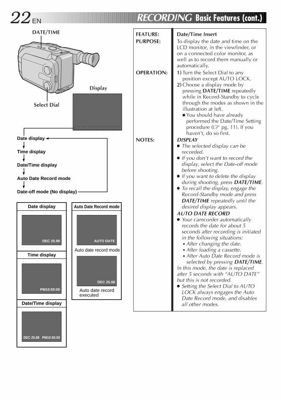
Auto Date Record mode
Date display
Time display
Date/Time display
Date-off mode (No display)
PM10:50:00
Date display
Time display
Date/Time display
DEC 25.98
DEC 25.98 PM10:50:00
Auto date record mode
Auto date record executed
DEC 25.98
AUTO DATE
Auto Date Record mode
DATE/TIME
Display
Select Dial
FEATURE: Date/Time InsertPURPOSE: To display the date and time on the
LCD monitor, in the viewfinder, oron a connected color monitor, aswell as to record them manually orautomatically.
OPERATION: 1) Turn the Select Dial to anyposition except AUTO LOCK.
2) Choose a display mode bypressing DATE/TIME repeatedlywhile in Record-Standby to cyclethrough the modes as shown in theillustration at left.n You should have already
performed the Date/Time Settingprocedure (Z pg. 11). If youhaven’t, do so first.
NOTES: DISPLAY● The selected display can be
recorded.● If you don’t want to record the
display, select the Date-off modebefore shooting.
● If you want to delete the displayduring shooting, press DATE/TIME.
● To recall the display, engage theRecord-Standby mode and pressDATE/TIME repeatedly until thedesired display appears.
AUTO DATE RECORD● Your camcorder automatically
records the date for about 5seconds after recording is initiatedin the following situations:• After changing the date.• After loading a cassette.• After Auto Date Record mode is
selected by pressing DATE/TIME.In this mode, the date is replacedafter 5 seconds with “AUTO DATE”but this is not recorded.● Setting the Select Dial to AUTO
LOCK always engages the AutoDate Record mode, and disablesall other modes.
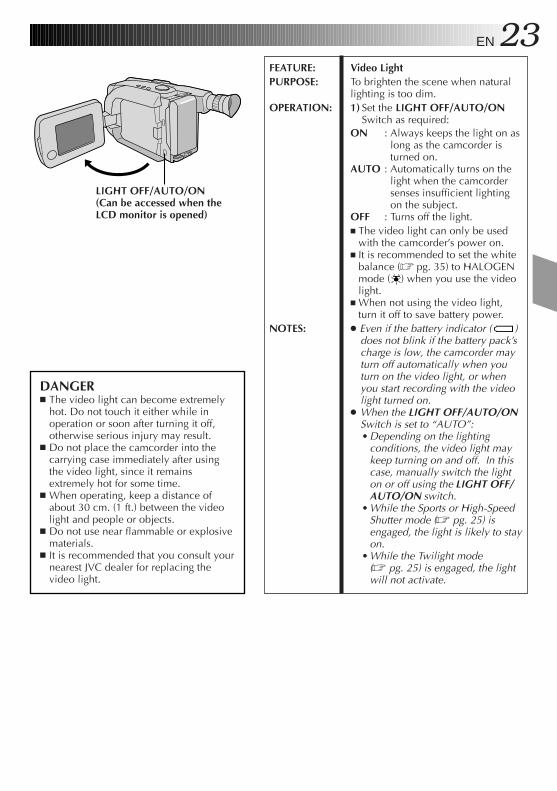
EN 23FEATURE: Video LightPURPOSE: To brighten the scene when natural
lighting is too dim.OPERATION: 1) Set the LIGHT OFF/AUTO/ON
Switch as required:ON : Always keeps the light on as
long as the camcorder isturned on.
AUTO : Automatically turns on thelight when the camcordersenses insufficient lightingon the subject.
OFF : Turns off the light.n The video light can only be used
with the camcorder’s power on.n It is recommended to set the white
balance (Z pg. 35) to HALOGENmode ( ) when you use the videolight.
n When not using the video light,turn it off to save battery power.
NOTES: ● Even if the battery indicator ( )does not blink if the battery pack’scharge is low, the camcorder mayturn off automatically when youturn on the video light, or whenyou start recording with the videolight turned on.
● When the LIGHT OFF/AUTO/ONSwitch is set to “AUTO”:• Depending on the lighting
conditions, the video light maykeep turning on and off. In thiscase, manually switch the lighton or off using the LIGHT OFF/AUTO/ON switch.
• While the Sports or High-SpeedShutter mode (Z pg. 25) isengaged, the light is likely to stayon.
• While the Twilight mode(Z pg. 25) is engaged, the lightwill not activate.
DANGERn The video light can become extremely
hot. Do not touch it either while inoperation or soon after turning it off,otherwise serious injury may result.
n Do not place the camcorder into thecarrying case immediately after usingthe video light, since it remainsextremely hot for some time.
n When operating, keep a distance ofabout 30 cm. (1 ft.) between the videolight and people or objects.
n Do not use near flammable or explosivematerials.
n It is recommended that you consult yournearest JVC dealer for replacing thevideo light.
LIGHT OFF/AUTO/ON(Can be accessed when theLCD monitor is opened)
24 EN RECORDING Advanced Features
1/2
000
FGND
AUTO MODE
LOCK RELEASE
SEPIA
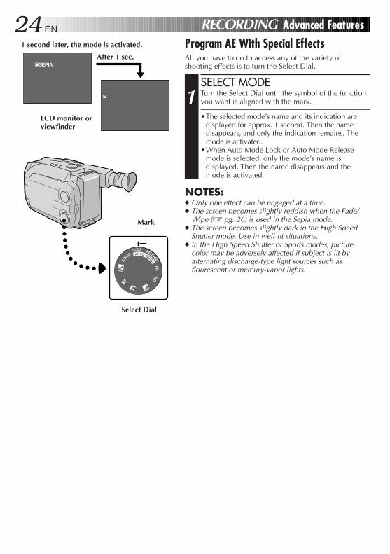
Program AE With Special EffectsAll you have to do to access any of the variety ofshooting effects is to turn the Select Dial.
SELECT MODE
1 Turn the Select Dial until the symbol of the functionyou want is aligned with the mark.
•The selected mode’s name and its indication aredisplayed for approx. 1 second. Then the namedisappears, and only the indication remains. Themode is activated.
•When Auto Mode Lock or Auto Mode Releasemode is selected, only the mode’s name isdisplayed. Then the name disappears and themode is activated.
NOTES:● Only one effect can be engaged at a time.● The screen becomes slightly reddish when the Fade/
Wipe (Z pg. 26) is used in the Sepia mode.● The screen becomes slightly dark in the High Speed
Shutter mode. Use in well-lit situations.● In the High Speed Shutter or Sports modes, picture
color may be adversely affected if subject is lit byalternating discharge-type light sources such asflourescent or mercury-vapor lights.
After 1 sec.
1 second later, the mode is activated.
Select Dial
LCD monitor orviewfinder
Mark
EN 25Dial LCD monitor/
Modesymbol Viewfinder indication
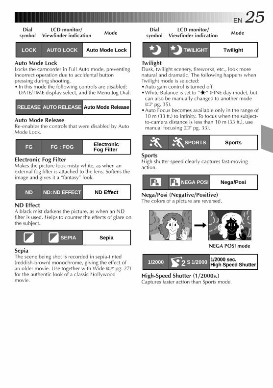
Auto Mode LockLOCK AUTO LOCK
Auto Mode LockLocks the camcorder in Full Auto mode, preventingincorrect operation due to accidental buttonpressing during shooting.• In this mode the following controls are disabled;
DATE/TIME display select, and the Menu Jog Dial.
Auto Mode ReleaseRELEASE AUTO RELEASE
Auto Mode ReleaseRe-enables the controls that were disabled by AutoMode Lock.
Electronic Fog FilterFG FG : FOG
Electronic Fog FilterMakes the picture look misty white, as when anexternal fog filter is attached to the lens. Softens theimage and gives it a “fantasy” look.
ND EffectND ND:ND EFFECT
ND EffectA black mist darkens the picture, as when an NDfilter is used. Helps to counter the effects of glare onthe subject.
SepiaSEPIA
SepiaThe scene being shot is recorded in sepia-tinted(reddish-brown) monochrome, giving the effect ofan older movie. Use together with Wide (Z pg. 27)for the authentic look of a classic Hollywoodmovie.
Dial LCD monitor/Modesymbol Viewfinder indication
TwilightTWILIGHT
TwilightDusk, twilight scenery, fireworks, etc., look morenatural and dramatic. The following happens whenTwilight mode is selected:•Auto gain control is turned off.•White Balance is set to “ ” (FINE day mode), but
can also be manually changed to another mode(Z pg. 35).
•Auto Focus becomes available only in the range of10 m (33 ft.) to infinity. To focus when the subject-to-camera distance is less than 10 m (33 ft.), usemanual focusing (Z pg. 33).
SportsSPORTS
SportsHigh shutter speed clearly captures fast-movingaction.
Nega/PosiNEGA POSI
Nega/Posi (Negative/Positive)The colors of a picture are reversed.
1/2000 sec.High Speed Shutter1/2000 S 1/20002
High-Speed Shutter (1/2000s.)Captures faster action than Sports mode.
NEGA POSI mode
26 EN
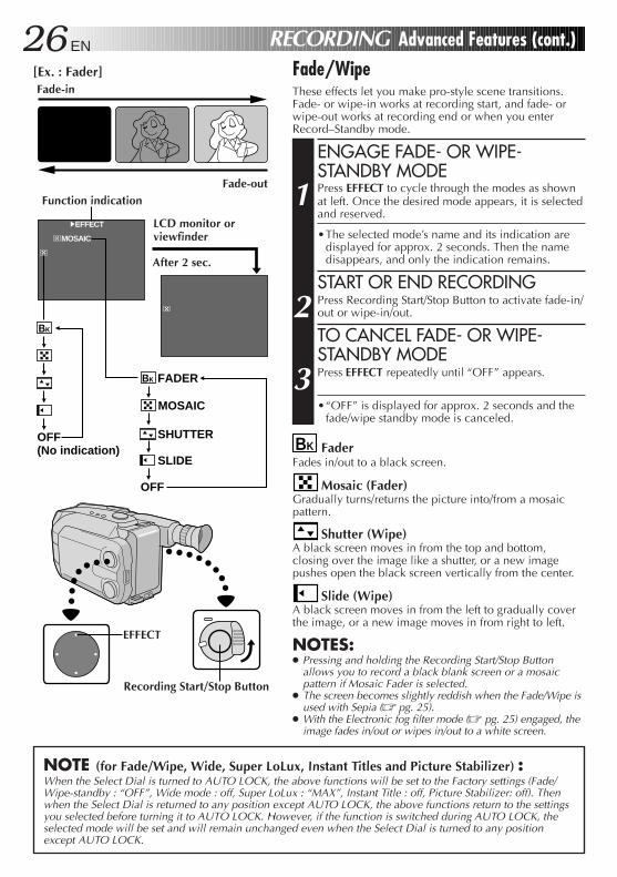
BK FaderFades in/out to a black screen.
Mosaic (Fader)Gradually turns/returns the picture into/from a mosaicpattern.
Shutter (Wipe)A black screen moves in from the top and bottom,closing over the image like a shutter, or a new imagepushes open the black screen vertically from the center.
Slide (Wipe)A black screen moves in from the left to gradually coverthe image, or a new image moves in from right to left.
NOTES:● Pressing and holding the Recording Start/Stop Button
allows you to record a black blank screen or a mosaicpattern if Mosaic Fader is selected.
● The screen becomes slightly reddish when the Fade/Wipe isused with Sepia (Z pg. 25).
● With the Electronic fog filter mode (Z pg. 25) engaged, theimage fades in/out or wipes in/out to a white screen.
MOSAIC
4EFFECT
OFF (No indication)
OFF
BK
FADER
MOSAIC
SHUTTER
SLIDE
BK
RECORDING Advanced Features (cont.)
Fade-in
Fade-out
Fade/WipeThese effects let you make pro-style scene transitions.Fade- or wipe-in works at recording start, and fade- orwipe-out works at recording end or when you enterRecord–Standby mode.
ENGAGE FADE- OR WIPE-STANDBY MODE
1 Press EFFECT to cycle through the modes as shownat left. Once the desired mode appears, it is selectedand reserved.
•The selected mode’s name and its indication aredisplayed for approx. 2 seconds. Then the namedisappears, and only the indication remains.
START OR END RECORDING
2 Press Recording Start/Stop Button to activate fade-in/out or wipe-in/out.
TO CANCEL FADE- OR WIPE-STANDBY MODE
3 Press EFFECT repeatedly until “OFF” appears.
•“OFF” is displayed for approx. 2 seconds and thefade/wipe standby mode is canceled.
NOTE (for Fade/Wipe, Wide, Super LoLux, Instant Titles and Picture Stabilizer) :When the Select Dial is turned to AUTO LOCK, the above functions will be set to the Factory settings (Fade/Wipe-standby : “OFF”, Wide mode : off, Super LoLux : “MAX”, Instant Title : off, Picture Stabilizer: off). Thenwhen the Select Dial is returned to any position except AUTO LOCK, the above functions return to the settingsyou selected before turning it to AUTO LOCK. However, if the function is switched during AUTO LOCK, theselected mode will be set and will remain unchanged even when the Select Dial is turned to any positionexcept AUTO LOCK.
[Ex. : Fader]
Recording Start/Stop Button
Function indication
EFFECT
After 2 sec.
LCD monitor orviewfinder
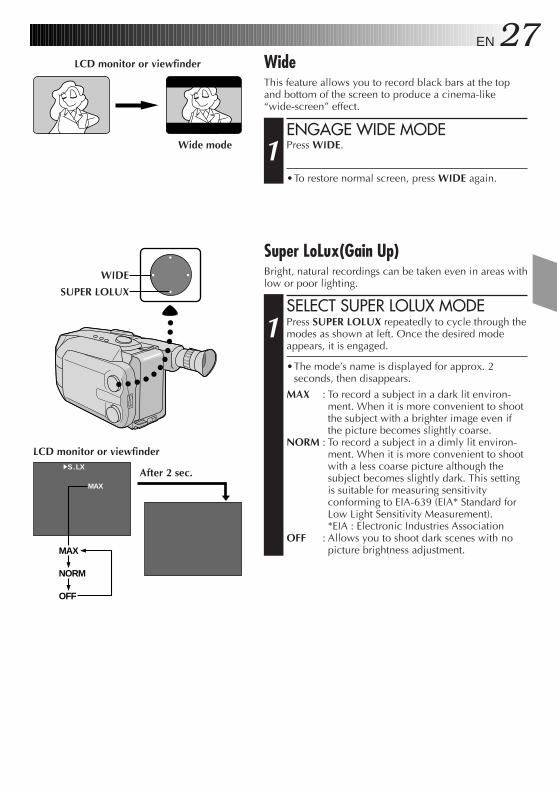
EN 27LCD monitor or viewfinder Wide
This feature allows you to record black bars at the topand bottom of the screen to produce a cinema-like“wide-screen” effect.
ENGAGE WIDE MODE
1 Press WIDE.
•To restore normal screen, press WIDE again.
4S.LX
MAX
MAX
NORM
OFF
Super LoLux(Gain Up)Bright, natural recordings can be taken even in areas withlow or poor lighting.
SELECT SUPER LOLUX MODE
1 Press SUPER LOLUX repeatedly to cycle through themodes as shown at left. Once the desired modeappears, it is engaged.
•The mode’s name is displayed for approx. 2seconds, then disappears.
MAX : To record a subject in a dark lit environ-ment. When it is more convenient to shootthe subject with a brighter image even ifthe picture becomes slightly coarse.
NORM : To record a subject in a dimly lit environ-ment. When it is more convenient to shootwith a less coarse picture although thesubject becomes slightly dark. This settingis suitable for measuring sensitivityconforming to EIA-639 (EIA* Standard forLow Light Sensitivity Measurement).*EIA : Electronic Industries Association
OFF : Allows you to shoot dark scenes with nopicture brightness adjustment.
LCD monitor or viewfinder
WIDE
SUPER LOLUX
Wide mode
After 2 sec.
28 EN
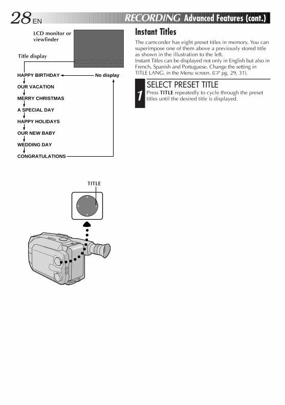
Instant TitlesThe camcorder has eight preset titles in memory. You cansuperimpose one of them above a previously stored titleas shown in the illustration to the left.Instant Titles can be displayed not only in English but also inFrench, Spanish and Portuguese. Change the setting inTITLE LANG. in the Menu screen. (Z pg. 29, 31).
SELECT PRESET TITLE
1 Press TITLE repeatedly to cycle through the presettitles until the desired title is displayed.
A SPECIAL DAY
HAPPY BIRTHDAY No display
OUR VACATION
MERRY CHRISTMAS
HAPPY HOLIDAYS
OUR NEW BABY
WEDDING DAY
CONGRATULATIONS
Title display
RECORDING Advanced Features (cont.)
TITLE
LCD monitor orviewfinder
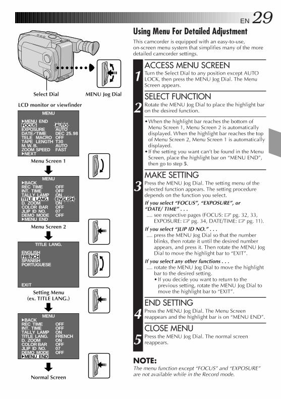
EN 29Using Menu For Detailed AdjustmentThis camcorder is equipped with an easy-to-use,on-screen menu system that simplifies many of the moredetailed camcorder settings.
ACCESS MENU SCREEN
1 Turn the Select Dial to any position except AUTOLOCK, then press the MENU Jog Dial. The MenuScreen appears.
SELECT FUNCTION
2 Rotate the MENU Jog Dial to place the highlight baron the desired function.
•When the highlight bar reaches the bottom ofMenu Screen 1, Menu Screen 2 is automaticallydisplayed. When the highlight bar reaches the topof Menu Screen 2, Menu Screen 1 is automaticallydisplayed.
•If the setting you want can’t be found in the MenuScreen, place the highlight bar on “MENU END”,then go to step 5.
MAKE SETTING
3 Press the MENU Jog Dial. The setting menu of theselected function appears. The setting proceduredepends on the function you select.If you select “FOCUS”, “EXPOSURE”, or“DATE/ TIME” . . ..... see respective pages (FOCUS: Z pg. 32, 33,
EXPOSURE: Z pg. 34, DATE/TIME: Z pg. 11).
If you select “JLIP ID NO.” . . ..... press the MENU Jog Dial so that the number
blinks, then rotate it until the desired numberappears, and press it. Then rotate the MENU JogDial to move the highlight bar to “EXIT”.
If you select any other functions . . ..... rotate the MENU Jog Dial to move the highlight
bar to the desired setting.• If you decide you want to return to the
previous setting, rotate the MENU Jog Dial tomove the highlight bar to “EXIT”.
END SETTING
4 Press the MENU Jog Dial. The Menu Screenreappears and the highlight bar is on “MENU END”.
CLOSE MENU
5 Press the MENU Jog Dial. The normal screenreappears.
NOTE:The menu function except “FOCUS” and “EXPOSURE”are not available while in the Record mode.
TITLE LANG.
ENGLISHFRENCHSPANISHPORTUGUESE
EXIT
MENU
4MENU ENDFOCUSEXPOSUREDATE TIMETELE MACROTAPE LENGTHM. W. B.ZOOM SPEED4NEXT
AUTOAUTODECOFFT30AUTOFAST
MENU4BACKREC TIMEINT. TIMETALLY LAMPTITLE LANG.D. ZOOMCOLOR BARJLIP ID NO.DEMO MODE4MENU END
OFFOFFONENGLISHONOFF07OFF
MENU4BACKREC TIMEINT. TIMETALLY LAMPTITLE LANG.D. ZOOMCOLOR BARJLIP ID NO.DEMO MODE4MENU END
OFFOFFONFRENCHONOFF07OFF
25.98
Normal Screen
LCD monitor or viewfinder
Menu Screen 1
Menu Screen 2
Setting Menu(ex. TITLE LANG.)
MENU Jog DialSelect Dial
30 EN RECORDING Advanced Features (cont.)
AUTO
MANU
AUTO
MANU
OFF
ON
FAST
SLOW
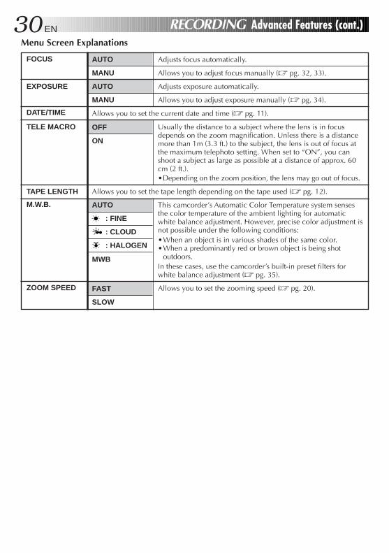
Adjusts focus automatically.
Allows you to adjust focus manually (Z pg. 32, 33).
Adjusts exposure automatically.
Allows you to adjust exposure manually (Z pg. 34).
Allows you to set the current date and time (Z pg. 11).
Usually the distance to a subject where the lens is in focusdepends on the zoom magnification. Unless there is a distancemore than 1m (3.3 ft.) to the subject, the lens is out of focus atthe maximum telephoto setting. When set to “ON”, you canshoot a subject as large as possible at a distance of approx. 60cm (2 ft.).•Depending on the zoom position, the lens may go out of focus.
Allows you to set the tape length depending on the tape used (Z pg. 12).
This camcorder’s Automatic Color Temperature system sensesthe color temperature of the ambient lighting for automaticwhite balance adjustment. However, precise color adjustment isnot possible under the following conditions:•When an object is in various shades of the same color.•When a predominantly red or brown object is being shot
outdoors.In these cases, use the camcorder’s built-in preset filters forwhite balance adjustment (Z pg. 35).
Allows you to set the zooming speed (Z pg. 20).
Menu Screen Explanations
FOCUS
EXPOSURE
DATE/TIME
TELE MACRO
TAPE LENGTH
M.W.B.
ZOOM SPEED
AUTO
: FINE
: CLOUD
: HALOGEN
MWB
EN 31
= Factory setting and when the Select Dial is set to AUTO LOCK
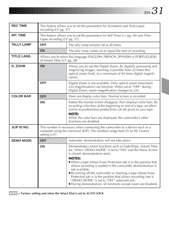
This feature allows you to set the parameters for Animation and Time-Lapserecording (Z pg. 37).
This feature allows you to set the parameters for Self-Timer (Z pg. 36) and Time-Lapse recording (Z pg. 37).
The tally lamp remains off at all times.
The tally lamp comes on to signal the start of recording.
Allows you to select the language (ENGLISH, FRENCH, SPANISH or PORTUGUESE)of Instant Titles (Z pg. 28)
Allows you to use the Digital Zoom. By digitally processing andmagnifying images, zooming is possible from 22 times (theoptical zoom limit), to a maximum of 44 times digital magnifi-cation.
Digital Zoom is not available. Only optical zoom (maximum22x magnification) can function. When set to “OFF” duringDigital Zoom, zoom magnification changes to 22x.
Does not display color bars. Normal screen is recorded.
Makes the normal screen disappear, then displays color bars. Byrecording color bars at the beginning or end of a tape, an effectsimilar to professional productions can be given to your tape.NOTE:While the color bars are displayed, the camcorder’s otherfunctions are disabled.
This number is necessary when connecting the camcorder to a device such as acomputer using the J terminal (JLIP). The numbers range from 01 to 99. Factorysetting is 07.
Automatic demonstration will not take place.
Demonstrates certain functions such as Fade/Wipe, Instant Titlesetc. When “DEMO MODE” is set to “ON” and the Menu Screenis closed, demonstration starts.
NOTES:● When a tape whose Erase Protection tab is in the position that
allows recording is loaded in the camcorder, demonstration isnot available.
● By turning off the camcorder or inserting a tape whose EraseProtection tab is in the position that allows recording into it,“DEMO MODE” is set to “OFF” automatically.
● During demonstration, all functions except zoom are disabled.
OFF
ON
OFF
ON
ON
OFF
OFF
ON
REC TIME
D. ZOOM
COLOR BAR
TITLE LANG.
JLIP ID NO.
DEMO MODE
INT. TIME
TALLY LAMP
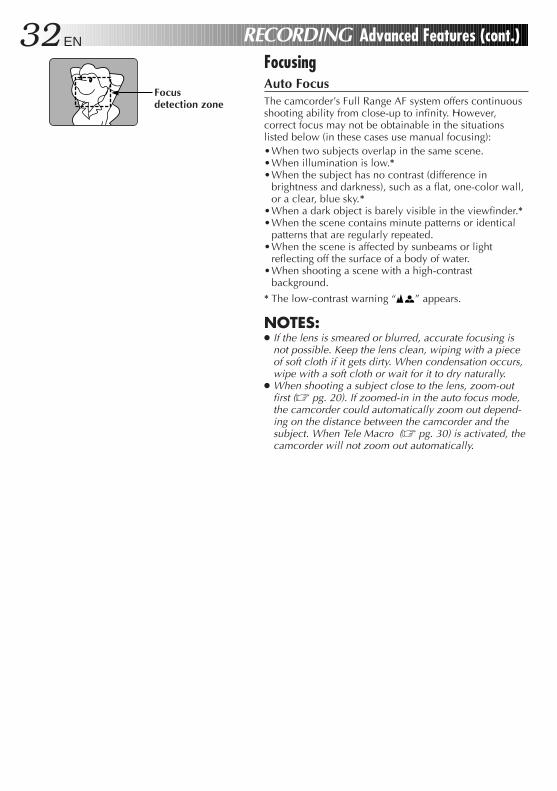
32 EN
FocusingAuto FocusThe camcorder’s Full Range AF system offers continuousshooting ability from close-up to infinity. However,correct focus may not be obtainable in the situationslisted below (in these cases use manual focusing):•When two subjects overlap in the same scene.•When illumination is low.*•When the subject has no contrast (difference in
brightness and darkness), such as a flat, one-color wall,or a clear, blue sky.*
•When a dark object is barely visible in the viewfinder.*•When the scene contains minute patterns or identical
patterns that are regularly repeated.•When the scene is affected by sunbeams or light
reflecting off the surface of a body of water.•When shooting a scene with a high-contrast
background.
* The low-contrast warning “ ” appears.
NOTES:● If the lens is smeared or blurred, accurate focusing is
not possible. Keep the lens clean, wiping with a pieceof soft cloth if it gets dirty. When condensation occurs,wipe with a soft cloth or wait for it to dry naturally.
● When shooting a subject close to the lens, zoom-outfirst (Z pg. 20). If zoomed-in in the auto focus mode,the camcorder could automatically zoom out depend-ing on the distance between the camcorder and thesubject. When Tele Macro (Z pg. 30) is activated, thecamcorder will not zoom out automatically.
Focusdetection zone
RECORDING Advanced Features (cont.)
EN 33
MENU
4MENU ENDFOCUSEXPOSUREDATE TIMETELE MACROTAPE LENGTHM. W. B.ZOOM SPEED4NEXT
AUTOAUTODECOFFT30AUTOFAST
25.98
AUTOMANU
EXIT
FOCUS
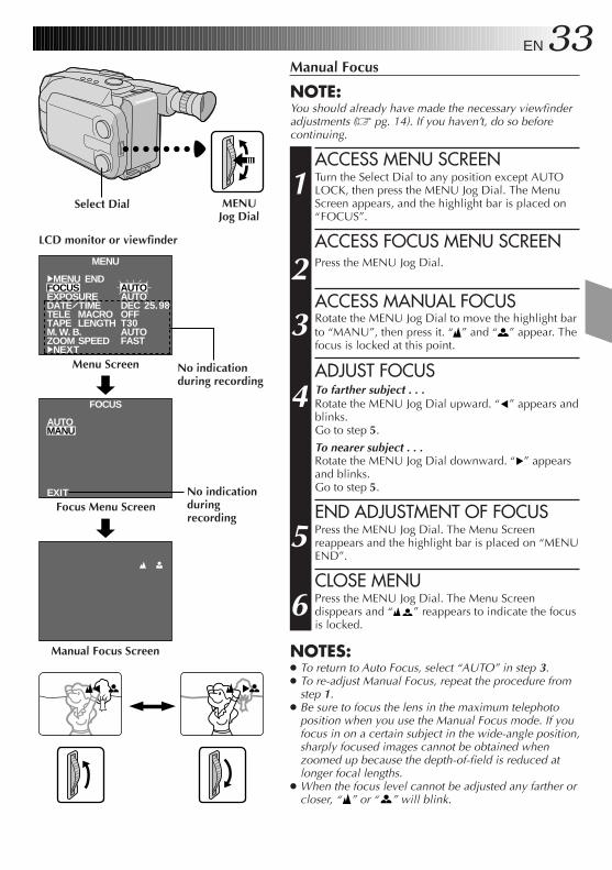
Manual Focus
NOTE:You should already have made the necessary viewfinderadjustments (Z pg. 14). If you haven’t, do so beforecontinuing.
ACCESS MENU SCREEN
1 Turn the Select Dial to any position except AUTOLOCK, then press the MENU Jog Dial. The MenuScreen appears, and the highlight bar is placed on“FOCUS”.
ACCESS FOCUS MENU SCREEN
2 Press the MENU Jog Dial.
ACCESS MANUAL FOCUS
3 Rotate the MENU Jog Dial to move the highlight barto “MANU”, then press it. “ ” and “ ” appear. Thefocus is locked at this point.
ADJUST FOCUS
4 To farther subject . . .Rotate the MENU Jog Dial upward. “ ” appears andblinks.Go to step 5.
To nearer subject . . .Rotate the MENU Jog Dial downward. “ ” appearsand blinks.Go to step 5.
END ADJUSTMENT OF FOCUS
5 Press the MENU Jog Dial. The Menu Screenreappears and the highlight bar is placed on “MENUEND”.
CLOSE MENU
6 Press the MENU Jog Dial. The Menu Screendisppears and “ ” reappears to indicate the focusis locked.
NOTES:● To return to Auto Focus, select “AUTO” in step 3.● To re-adjust Manual Focus, repeat the procedure from
step 1.● Be sure to focus the lens in the maximum telephoto
position when you use the Manual Focus mode. If youfocus in on a certain subject in the wide-angle position,sharply focused images cannot be obtained whenzoomed up because the depth-of-field is reduced atlonger focal lengths.
● When the focus level cannot be adjusted any farther orcloser, “ ” or “ ” will blink.
LCD monitor or viewfinder
MENUJog Dial
Manual Focus Screen
Focus Menu Screen
Menu Screen
Select Dial
No indicationduring recording
No indicationduringrecording
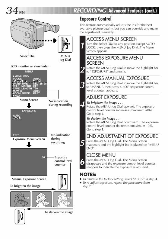
34 EN RECORDING Advanced Features (cont.)Exposure ControlThis feature automatically adjusts the iris for the bestavailable picture quality, but you can override and makethe adjustment manually.
ACCESS MENU SCREEN
1 Turn the Select Dial to any position except AUTOLOCK, then press the MENU Jog Dial. The MenuScreen appears.
ACCESS EXPOSURE MENUSCREEN
2 Rotate the MENU Jog Dial to move the highlight barto “EXPOSURE” and press it.
ACCESS MANUAL EXPOSURE
3 Rotate the MENU Jog Dial to move the highlight barto “MANU”, then press it. “00” (exposure controllevel counter) appears.
ADJUST EXPOSURE
4 To brighten the image . . .Rotate the MENU Jog Dial upward. The exposurecontrol level counter increases (maximum +06).Go to step 5.
To darken the image . . .Rotate the MENU Jog Dial downward. The exposurecontrol level counter decreases (maximum –06).Go to step 5.
END ADJUSTMENT OF EXPOSURE
5 Press the MENU Jog Dial. The Menu Screenreappears and the highlight bar is placed on “MENUEND”.
CLOSE MENU
6 Press the MENU Jog Dial. The Menu Screendisappears and the exposure control level counterreappers to indicate the exposure is adjusted.
NOTES:● To return to the factory setting, select “AUTO” in step 3.● To re-adjust exposure, repeat the procedure from
step 1.
MENU
4MENU ENDFOCUSEXPOSUREDATE TIMETELE MACROTAPE LENGTHM. W. B.ZOOM SPEED4NEXT
AUTOAUTODECOFFT30AUTOFAST
25.98
+06–06
00
AUTOMANU
EXIT
EXPOSURE
LCD monitor or viewfinder
To darken the image
To brighten the image
Menu Screen
Exposure Menu Screen
Manual Exposure Screen
MENUJog Dial
No indicationduringrecording
Exposurecontrol levelcounter
Select Dial
No indicationduring recording
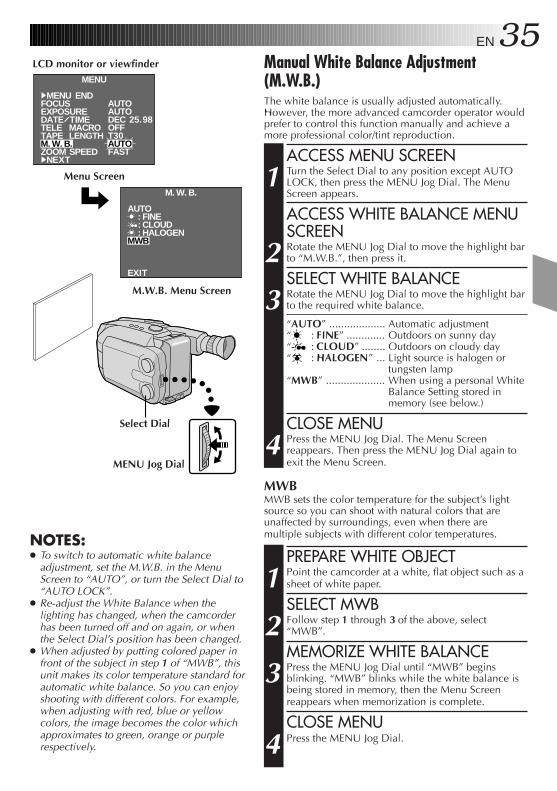
EN 35Manual White Balance Adjustment(M.W.B.)The white balance is usually adjusted automatically.However, the more advanced camcorder operator wouldprefer to control this function manually and achieve amore professional color/tint reproduction.
ACCESS MENU SCREEN
1 Turn the Select Dial to any position except AUTOLOCK, then press the MENU Jog Dial. The MenuScreen appears.
ACCESS WHITE BALANCE MENUSCREEN
2 Rotate the MENU Jog Dial to move the highlight barto “M.W.B.”, then press it.
SELECT WHITE BALANCE
3 Rotate the MENU Jog Dial to move the highlight barto the required white balance.
“AUTO” ................... Automatic adjustment“ : FINE” ............. Outdoors on sunny day“ : CLOUD” ........ Outdoors on cloudy day“ : HALOGEN” ... Light source is halogen or
tungsten lamp“MWB” .................... When using a personal White
Balance Setting stored inmemory (see below.)
CLOSE MENU
4 Press the MENU Jog Dial. The Menu Screenreappears. Then press the MENU Jog Dial again toexit the Menu Screen.
MWBMWB sets the color temperature for the subject’s lightsource so you can shoot with natural colors that areunaffected by surroundings, even when there aremultiple subjects with different color temperatures.
PREPARE WHITE OBJECT
1 Point the camcorder at a white, flat object such as asheet of white paper.
SELECT MWB
2 Follow step 1 through 3 of the above, select“MWB”.
MEMORIZE WHITE BALANCE
3 Press the MENU Jog Dial until “MWB” beginsblinking. “MWB” blinks while the white balance isbeing stored in memory, then the Menu Screenreappears when memorization is complete.
CLOSE MENU
4 Press the MENU Jog Dial.
NOTES:● To switch to automatic white balance
adjustment, set the M.W.B. in the MenuScreen to “AUTO”, or turn the Select Dial to“AUTO LOCK”.
● Re-adjust the White Balance when thelighting has changed, when the camcorderhas been turned off and on again, or whenthe Select Dial’s position has been changed.
● When adjusted by putting colored paper infront of the subject in step 1 of “MWB”, thisunit makes its color temperature standard forautomatic white balance. So you can enjoyshooting with different colors. For example,when adjusting with red, blue or yellowcolors, the image becomes the color whichapproximates to green, orange or purplerespectively.
MENU
4MENU ENDFOCUSEXPOSUREDATE TIMETELE MACROTAPE LENGTHM. W. B.ZOOM SPEED4NEXT
AUTOAUTODECOFFT30AUTOFAST
25.98
AUTO : FINE : CLOUD : HALOGENMWB
EXIT
M. W. B.
LCD monitor or viewfinder
Menu Screen
M.W.B. Menu Screen
Select Dial
MENU Jog Dial
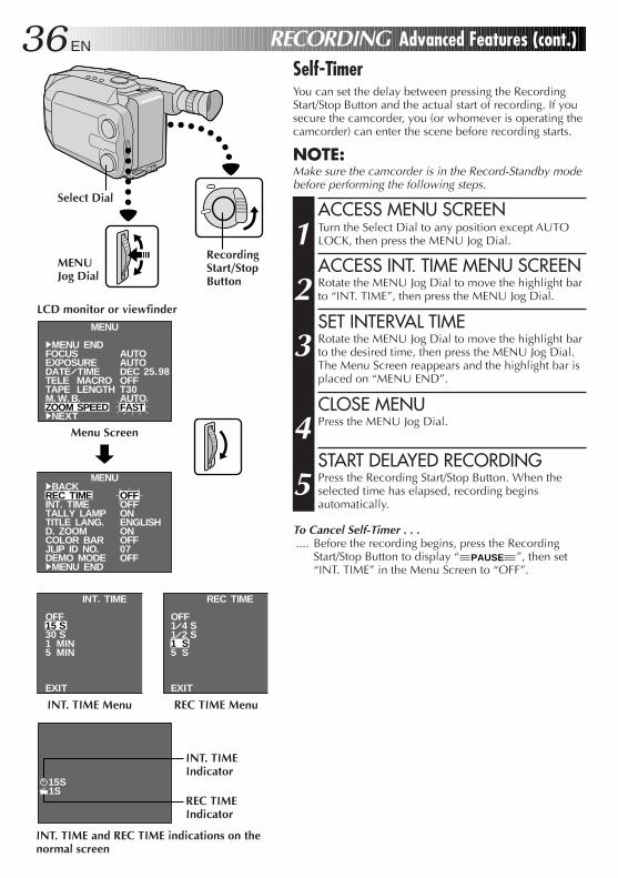
36 EN RECORDING Advanced Features (cont.)Self-TimerYou can set the delay between pressing the RecordingStart/Stop Button and the actual start of recording. If yousecure the camcorder, you (or whomever is operating thecamcorder) can enter the scene before recording starts.
NOTE:Make sure the camcorder is in the Record-Standby modebefore performing the following steps.
ACCESS MENU SCREEN
1 Turn the Select Dial to any position except AUTOLOCK, then press the MENU Jog Dial.
ACCESS INT. TIME MENU SCREEN
2 Rotate the MENU Jog Dial to move the highlight barto “INT. TIME”, then press the MENU Jog Dial.
SET INTERVAL TIME
3 Rotate the MENU Jog Dial to move the highlight barto the desired time, then press the MENU Jog Dial.The Menu Screen reappears and the highlight bar isplaced on “MENU END”.
CLOSE MENU
4 Press the MENU Jog Dial.
START DELAYED RECORDING
5 Press the Recording Start/Stop Button. When theselected time has elapsed, recording beginsautomatically.
To Cancel Self-Timer . . ..... Before the recording begins, press the Recording
Start/Stop Button to display “ PAUSE ”, then set“INT. TIME” in the Menu Screen to “OFF”.
MENU
4MENU ENDFOCUSEXPOSUREDATE TIMETELE MACROTAPE LENGTHM. W. B.ZOOM SPEED4NEXT
AUTOAUTODECOFFT30AUTOFAST
25.98
MENU4BACKREC TIMEINT. TIMETALLY LAMPTITLE LANG.D. ZOOMCOLOR BARJLIP ID NO.DEMO MODE4MENU END
OFFOFFONENGLISHONOFF07OFF
INT. TIME
OFF15 S30 S1 MIN5 MIN
EXIT
REC TIME
OFF1 4 S1 2 S1 S5 S
EXIT
15S1S
LCD monitor or viewfinder
Menu Screen
REC TIME MenuINT. TIME Menu
RecordingStart/StopButton
INT. TIME and REC TIME indications on thenormal screen
Select Dial
MENUJog Dial
INT. TIMEIndicator
REC TIMEIndicator
EN 37AnimationGive stationary scenes or objects an illusion ofmovement. This function allows you to shoot aseries of pictures, each slightly different, of the sameobject for a brief period of time.
NOTE:Make sure the camcorder is in the Record-Standbymode and the recording mode is set to “SP” beforeperforming the following steps.
ACCESS MENU SCREEN
1 Turn the Select Dial to any position exceptAUTO LOCK, then press MENU Jog Dial.
SET RECORDING TIME
2 Rotate the MENU Jog Dial to move thehighlight bar to “REC TIME”, then press theMENU Jog Dial. The REC TIME Menu appears.Rotate the MENU Jog Dial to move thehighlight bar to the desired time, then press theMENU Jog Dial. The Menu Screen reappears.Press the MENU Jog Dial again to exit theMenu Screen.
START RECORDING
3 Press the Recording Start/Stop Button afterfocusing on the subject. The recording stopsautomatically after the selected period of time.
ASSEMBLE SERIES OFPICTURES
4 Repeat step 3 for the desired number ofpictures.
RELEASE ANIMATION MODE
5 Set “REC TIME” in the Menu screen to “OFF”.
NOTES:● For best results, make sure the camcorder is
secured when shooting in Animation orTime-Lapse mode.
● Fade- or Wipe-in/out cannot be performed duringAnimation or Time-Lapse shooting.
● Before performing other operations followingAnimation or Time-Lapse recording, make surethe Animation or Time-Lapse mode is deactivated.
● Self-Timer, Animation and Time-Lapse arecanceled when the power is shut off or when thecassette is ejected.
Time-LapseYou can record sequentially at preset time spans.Leaving the camcorder aimed at a specific subject,you can record subtle changes over an extendedperiod of time.
NOTE:Make sure the camcorder is in the Record-Standbymode and the recording mode is set to “SP” beforeperforming the following steps.
ACCESS MENU SCREEN
1 Turn the Select Dial to any position exceptAUTO LOCK, then press MENU Jog Dial.
SET INTERVAL BETWEENRECORDINGS
2 Rotate the MENU Jog Dial to move thehighlight bar to “INT. TIME”, then press theMENU Jog Dial. The INT. TIME Menu appears.Rotate the MENU Jog Dial to move thehighlight bar to the desired time, then press theMENU Jog Dial. The Menu Screen reappears.
SET RECORDING TIME
3 Rotate the MENU Jog Dial to move thehighlight bar to “REC TIME”, then press theMENU Jog Dial. The REC TIME Menu appears.Rotate the MENU Jog Dial to move thehighlight bar to the desired time, then press theMENU Jog Dial. The Menu Screen reappears.Press the MENU Jog Dial again to exit theMenu Screen.
START TIME-LAPSERECORDING
4 Press the Recording Start/Stop Button.Recording and intervals alternateautomatically.
RELEASE TIME-LAPSE MODE
5 To release when “ PAUSE ” is displayed, set“REC TIME” and “INT. TIME” in the MenuScreen to “OFF”. To release when“ PAUSE ” and “REC” are not displayed,press the Recording Start/Stop Button to display“ PAUSE ”, then set “REC TIME” and “INT.TIME” in the Menu Screen to “OFF”.
38 EN
M–1:23:45 SP 4
PLAYBACK Basic Playback
PLAY/PAUSE
STOP
FF
REW
LCD Monitor in Retracted Position
Tape runningindicator4 : Playback3 : Fast-Forward/
Forward Search2 : Rewind/Reverse
Search6 : Still Playback
Recording mode indicator
Tape counter
Battery pack remaining power indicator
LCD monitor/viewfinderindications
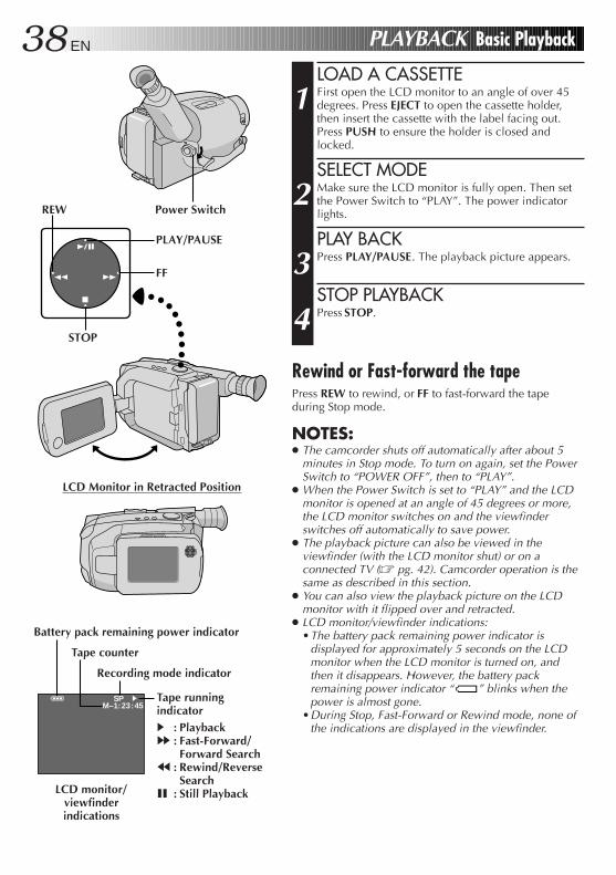
LOAD A CASSETTE
1 First open the LCD monitor to an angle of over 45degrees. Press EJECT to open the cassette holder,then insert the cassette with the label facing out.Press PUSH to ensure the holder is closed andlocked.
SELECT MODE
2 Make sure the LCD monitor is fully open. Then setthe Power Switch to “PLAY”. The power indicatorlights.
PLAY BACK
3 Press PLAY/PAUSE. The playback picture appears.
STOP PLAYBACK
4 Press STOP.
Rewind or Fast-forward the tapePress REW to rewind, or FF to fast-forward the tapeduring Stop mode.
NOTES:● The camcorder shuts off automatically after about 5
minutes in Stop mode. To turn on again, set the PowerSwitch to “POWER OFF”, then to “PLAY”.
● When the Power Switch is set to “PLAY” and the LCDmonitor is opened at an angle of 45 degrees or more,the LCD monitor switches on and the viewfinderswitches off automatically to save power.
● The playback picture can also be viewed in theviewfinder (with the LCD monitor shut) or on aconnected TV (Z pg. 42). Camcorder operation is thesame as described in this section.
● You can also view the playback picture on the LCDmonitor with it flipped over and retracted.
● LCD monitor/viewfinder indications:•The battery pack remaining power indicator is
displayed for approximately 5 seconds on the LCDmonitor when the LCD monitor is turned on, andthen it disappears. However, the battery packremaining power indicator “ ” blinks when thepower is almost gone.
•During Stop, Fast-Forward or Rewind mode, none ofthe indications are displayed in the viewfinder.
Power Switch
EN 39
AT
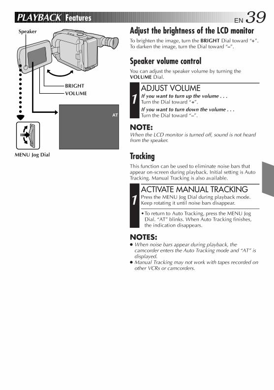
PLAYBACK FeaturesAdjust the brightness of the LCD monitorTo brighten the image, turn the BRIGHT Dial toward “+”.To darken the image, turn the Dial toward “–”.
Speaker volume controlYou can adjust the speaker volume by turning theVOLUME Dial.
ADJUST VOLUME
1 If you want to turn up the volume . . .Turn the Dial toward “+”.If you want to turn down the volume . . .Turn the Dial toward “–”.
NOTE:When the LCD monitor is turned off, sound is not heardfrom the speaker.
TrackingThis function can be used to eliminate noise bars thatappear on-screen during playback. Initial setting is AutoTracking. Manual Tracking is also available.
ACTIVATE MANUAL TRACKING
1 Press the MENU Jog Dial during playback mode.Keep rotating it until noise bars disappear.
•To return to Auto Tracking, press the MENU JogDial. “AT” blinks. When Auto Tracking finishes,the indication disappears.
NOTES:● When noise bars appear during playback, the
camcorder enters the Auto Tracking mode and “AT” isdisplayed.
● Manual Tracking may not work with tapes recorded onother VCRs or camcorders.
VOLUMEBRIGHT
MENU Jog Dial
Speaker
40 EN PLAYBACK Features (cont.)
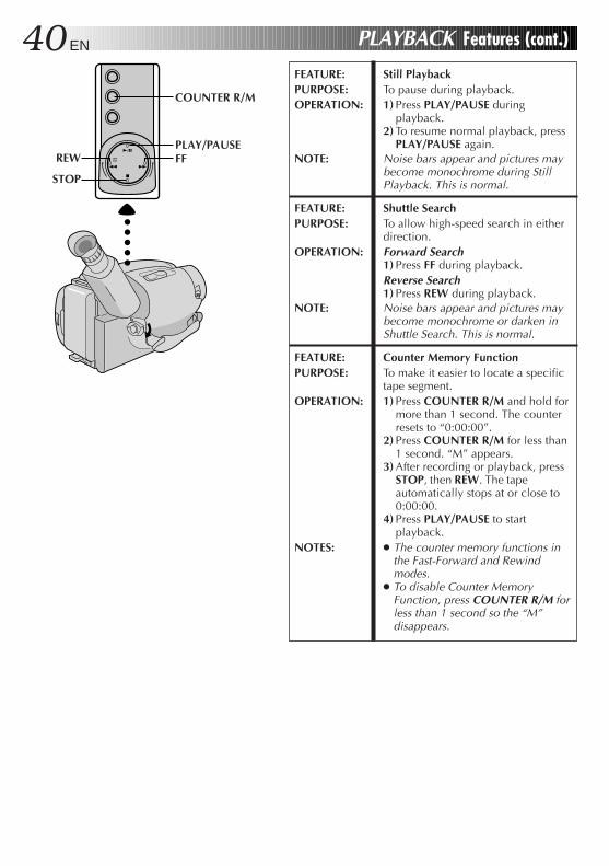
FEATURE: Still PlaybackPURPOSE: To pause during playback.OPERATION: 1) Press PLAY/PAUSE during
playback.2) To resume normal playback, press
PLAY/PAUSE again.NOTE: Noise bars appear and pictures may
become monochrome during StillPlayback. This is normal.
FEATURE: Shuttle SearchPURPOSE: To allow high-speed search in either
direction.OPERATION: Forward Search
1) Press FF during playback.Reverse Search1) Press REW during playback.
NOTE: Noise bars appear and pictures maybecome monochrome or darken inShuttle Search. This is normal.
FEATURE: Counter Memory FunctionPURPOSE: To make it easier to locate a specific
tape segment.OPERATION: 1) Press COUNTER R/M and hold for
more than 1 second. The counterresets to “0:00:00”.
2) Press COUNTER R/M for less than1 second. “M” appears.
3) After recording or playback, pressSTOP, then REW. The tapeautomatically stops at or close to0:00:00.
4) Press PLAY/PAUSE to startplayback.
NOTES: ● The counter memory functions inthe Fast-Forward and Rewindmodes.
● To disable Counter MemoryFunction, press COUNTER R/M forless than 1 second so the “M”disappears.
STOP
FFPLAY/PAUSE
COUNTER R/M
REW
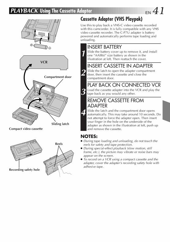
EN 41PLAYBACK Using The Cassette AdapterCassette Adapter (VHS Playpak)Use this to play back a VHS-C video cassette recordedwith this camcorder. It is fully compatible with any VHSvideo cassette recorder. The C-P7U adapter is batterypowered and automatically performs tape loading andunloading.
INSERT BATTERY
1 Slide the battery cover up to remove it, and installone “AA(R6)” size battery as shown in theillustration at left. Then reattach the cover.
INSERT CASSETTE IN ADAPTER
2 Slide the latch to open the adapter compartmentdoor, then insert the cassette and close thecompartment door.
PLAY BACK ON CONNECTED VCR
3 Load the cassette adapter into the VCR and play thetape back as you would any other.
REMOVE CASSETTE FROMADAPTER
4 Slide the latch and the compartment door opensautomatically. This may take around 10 seconds. Donot attempt to force the adapter open. Then insertyour finger in the hole on the underside of theadapter as shown in the illustration at left, push upand remove the cassette.
NOTES:● During tape loading and unloading, do not touch the
reels for safety and tape protection.● During special-effect playback (slow motion, still
frame, etc.), the picture may vibrate or noise bars mayappear on the screen.
● To record on a VCR using a compact cassette and theadapter, cover the adapter’s recording safety hole withadhesive tape.
VCR
Recording safety hole
Compartment door
Sliding latch
Compact video cassette
Reels
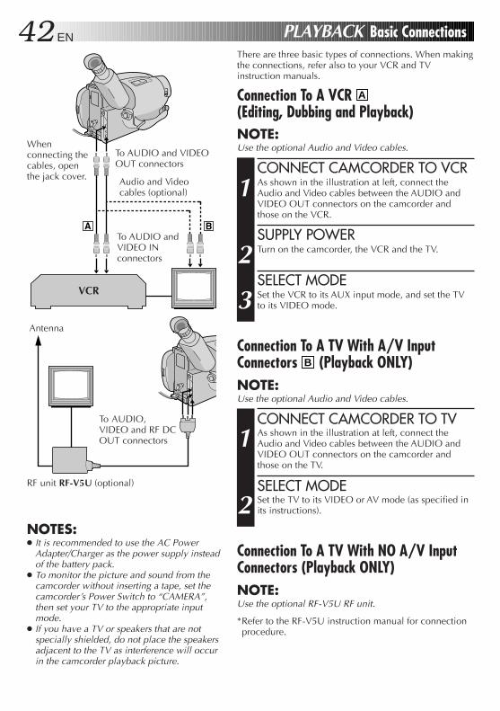
42 ENThere are three basic types of connections. When makingthe connections, refer also to your VCR and TVinstruction manuals.
Connection To A VCR A
(Editing, Dubbing and Playback)NOTE:Use the optional Audio and Video cables.
CONNECT CAMCORDER TO VCR
1 As shown in the illustration at left, connect theAudio and Video cables between the AUDIO andVIDEO OUT connectors on the camcorder andthose on the VCR.
SUPPLY POWER
2 Turn on the camcorder, the VCR and the TV.
SELECT MODE
3 Set the VCR to its AUX input mode, and set the TVto its VIDEO mode.
Connection To A TV With A/V InputConnectors B (Playback ONLY)NOTE:Use the optional Audio and Video cables.
CONNECT CAMCORDER TO TV
1 As shown in the illustration at left, connect theAudio and Video cables between the AUDIO andVIDEO OUT connectors on the camcorder andthose on the TV.
SELECT MODE
2 Set the TV to its VIDEO or AV mode (as specified inits instructions).
Connection To A TV With NO A/V InputConnectors (Playback ONLY)NOTE:Use the optional RF-V5U RF unit.
*Refer to the RF-V5U instruction manual for connectionprocedure.
NOTES:● It is recommended to use the AC Power
Adapter/Charger as the power supply insteadof the battery pack.
● To monitor the picture and sound from thecamcorder without inserting a tape, set thecamcorder’s Power Switch to “CAMERA”,then set your TV to the appropriate inputmode.
● If you have a TV or speakers that are notspecially shielded, do not place the speakersadjacent to the TV as interference will occurin the camcorder playback picture.
PLAYBACK Basic Connections
VCR
Whenconnecting thecables, openthe jack cover.
To AUDIO and VIDEOOUT connectors
Audio and Videocables (optional)
To AUDIO andVIDEO INconnectors
Antenna
RF unit RF-V5U (optional)
To AUDIO,VIDEO and RF DCOUT connectors
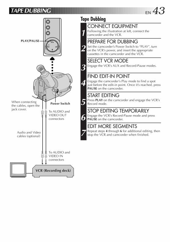
EN 43TAPE DUBBINGTape Dubbing
CONNECT EQUIPMENT
1 Following the illustration at left, connect thecamcorder and the VCR.
PREPARE FOR DUBBING
2 Set the camcorder’s Power Switch to “PLAY”, turnon the VCR’s power, and insert the appropriatecassettes in the camcorder and the VCR.
SELECT VCR MODE
3 Engage the VCR’s AUX and Record-Pause modes.
FIND EDIT-IN POINT
4 Engage the camcorder’s Play mode to find a spotjust before the edit-in point. Once it’s reached, pressPAUSE on the camcorder.
START EDITING
5 Press PLAY on the camcorder and engage the VCR’sRecord mode.
STOP EDITING TEMPORARILY
6 Engage the VCR’s Record-Pause mode and pressPAUSE on the camcorder.
EDIT MORE SEGMENTS
7 Repeat steps 4 through 6 for additional editing, thenstop the VCR and camcorder when finished.
VCR (Recording deck)
PLAY/PAUSE
To AUDIO andVIDEO OUTconnectors
When connectingthe cables, open thejack cover.
To AUDIO andVIDEO INconnectors
Audio and Videocables (optional)
Power Switch
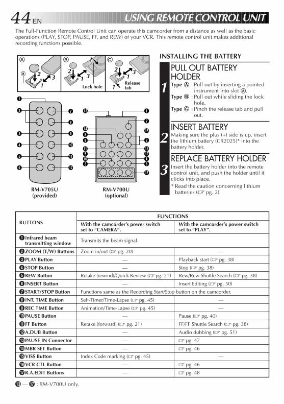
44 EN
A CB
a
2
1
3
4
5
6
7
8
9
0
!
@
# 1
$89
!503
7
%
^
2
@46
&
1
2 3 1
11
23 1
2 3
1
USING REMOTE CONTROL UNIT
BUTTONSFUNCTIONS
With the camcorder’s power switch With the camcorder’s power switchset to “CAMERA”. set to “PLAY”.
1 Infrared beam Transmits the beam signal.transmitting window
2 ZOOM (T/W) Buttons Zoom in/out (Z pg. 20) —
3 PLAY Button — Playback start (Z pg. 38)
4 STOP Button — Stop (Z pg. 38)
5 REW Button Retake (rewind)/Quick Review (Z pg. 21) Rew/Rew Shuttle Search (Z pg. 38)
6 INSERT Button — Insert Editing (Z pg. 50)
7 START/STOP Button Functions same as the Recording Start/Stop button on the camcorder.
8 INT. TIME Button Self-Timer/Time-Lapse (Z pg. 45) —
9 REC TIME Button Animation/Time-Lapse (Z pg. 45) —
0 PAUSE Button — Pause (Z pg. 40)
! FF Button Retake (forward) (Z pg. 21) FF/FF Shuttle Search (Z pg. 38)
@ A.DUB Button — Audio dubbing (Z pg. 51)
# PAUSE IN Connector — Z pg. 47
$ MBR SET Button — Z pg. 46
% VISS Button Index Code marking (Z pg. 45) —
^ VCR CTL Button — Z pg. 46
& R.A.EDIT Buttons — Z pg. 48
RM-V705U(provided)
RM-V700U(optional)
INSTALLING THE BATTERY
PULL OUT BATTERYHOLDER
1 Type A : Pull out by inserting a pointedinstrument into slot a .
Type B : Pull out while sliding the lockhole.
Type C : Pinch the release tab and pullout.
INSERT BATTERY
2 Making sure the plus (+) side is up, insertthe lithium battery (CR2025)* into thebattery holder.
REPLACE BATTERY HOLDER
3 Insert the battery holder into the remotecontrol unit, and push the holder until itclicks into place.* Read the caution concerning lithium
batteries (Z pg. 2).
# — & : RM-V700U only.
The Full-Function Remote Control Unit can operate this camcorder from a distance as well as the basicoperations (PLAY, STOP, PAUSE, FF, and REW) of your VCR. This remote control unit makes additionalrecording functions possible.
ReleasetabLock hole
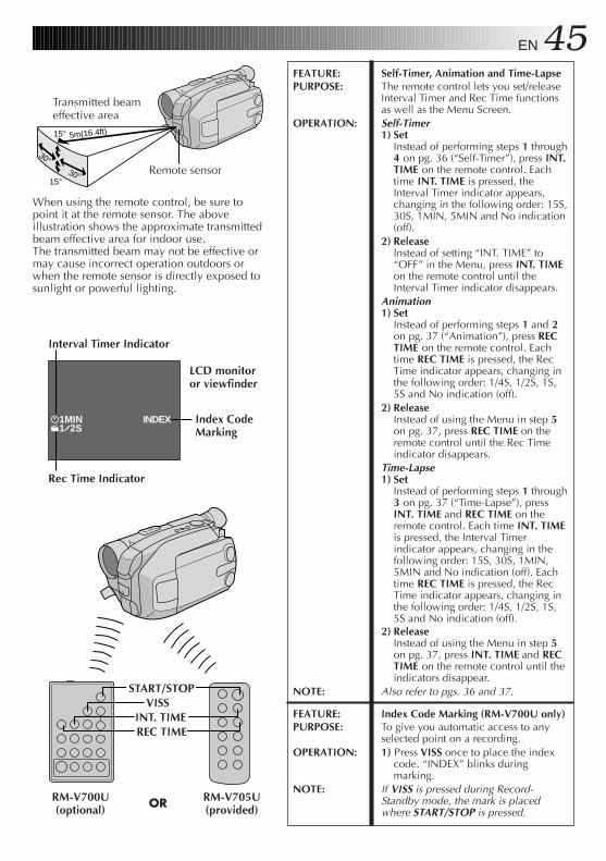
EN 45
INDEX1MIN1 2S
15° 5m(16.4ft)
15°30°
30°
FEATURE: Self-Timer, Animation and Time-LapsePURPOSE: The remote control lets you set/release
Interval Timer and Rec Time functionsas well as the Menu Screen.
OPERATION: Self-Timer1) Set
Instead of performing steps 1 through4 on pg. 36 (“Self-Timer”), press INT.TIME on the remote control. Eachtime INT. TIME is pressed, theInterval Timer indicator appears,changing in the following order: 15S,30S, 1MIN, 5MIN and No indication(off).
2) ReleaseInstead of setting “INT. TIME” to“OFF” in the Menu, press INT. TIMEon the remote control until theInterval Timer indicator disappears.
Animation1) Set
Instead of performing steps 1 and 2on pg. 37 (“Animation”), press RECTIME on the remote control. Eachtime REC TIME is pressed, the RecTime indicator appears, changing inthe following order: 1/4S, 1/2S, 1S,5S and No indication (off).
2) ReleaseInstead of using the Menu in step 5on pg. 37, press REC TIME on theremote control until the Rec Timeindicator disappears.
Time-Lapse1) Set
Instead of performing steps 1 through3 on pg. 37 (“Time-Lapse”), pressINT. TIME and REC TIME on theremote control. Each time INT. TIMEis pressed, the Interval Timerindicator appears, changing in thefollowing order: 15S, 30S, 1MIN,5MIN and No indication (off). Eachtime REC TIME is pressed, the RecTime indicator appears, changing inthe following order: 1/4S, 1/2S, 1S,5S and No indication (off).
2) ReleaseInstead of using the Menu in step 5on pg. 37, press INT. TIME and RECTIME on the remote control until theindicators disappear.
NOTE: Also refer to pgs. 36 and 37.
FEATURE: Index Code Marking (RM-V700U only)PURPOSE: To give you automatic access to any
selected point on a recording.OPERATION: 1) Press VISS once to place the index
code. “INDEX” blinks duringmarking.
NOTE: If VISS is pressed during Record-Standby mode, the mark is placedwhere START/STOP is pressed.
When using the remote control, be sure topoint it at the remote sensor. The aboveillustration shows the approximate transmittedbeam effective area for indoor use.The transmitted beam may not be effective ormay cause incorrect operation outdoors orwhen the remote sensor is directly exposed tosunlight or powerful lighting.
INT. TIMEREC TIME
START/STOPVISS
RM-V705U(provided)
RM-V700U(optional) OR
Interval Timer Indicator
Rec Time Indicator
Transmitted beameffective area
Remote sensor
LCD monitoror viewfinder
Index CodeMarking
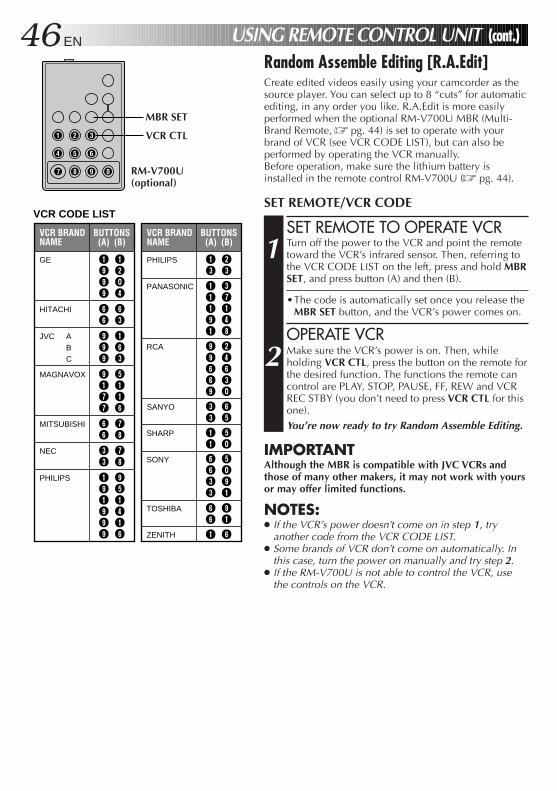
46 EN
1 2 3
4 5 6
7 8 9 0
VCR BRANDNAME
BUTTONS (A) (B)
GE 1 1 9 2 9 ` 9 4
MAGNAVOX 9 5 1 1 7 1 7 6
MITSUBISHI 6 7 6 8
NEC 3 7 3 8
PHILIPS 1 9 9 5 1 1 9 4 9 1 9 6
JVC 9 1 9 6 9 3
HITACHI 6 6 6 3
VCR BRANDNAME
BUTTONS (A) (B)
PHILIPS 1 2 3 3
SANYO 3 6 3 5
SHARP 1 5 1 `
SONY 6 5 6 ` 3 9 3 1 TOSHIBA 6 9 6 1
ZENITH 1 6
RCA 9 2 9 4 6 6 6 3 9 `
PANASONIC 1 3 1 7 1 1 9 4 1 8
VCR CODE LIST
ABC
USING REMOTE CONTROL UNIT (cont.)Random Assemble Editing [R.A.Edit]Create edited videos easily using your camcorder as thesource player. You can select up to 8 “cuts” for automaticediting, in any order you like. R.A.Edit is more easilyperformed when the optional RM-V700U MBR (Multi-Brand Remote, Z pg. 44) is set to operate with yourbrand of VCR (see VCR CODE LIST), but can also beperformed by operating the VCR manually.Before operation, make sure the lithium battery isinstalled in the remote control RM-V700U (Z pg. 44).
SET REMOTE/VCR CODE
SET REMOTE TO OPERATE VCR
1 Turn off the power to the VCR and point the remotetoward the VCR’s infrared sensor. Then, referring tothe VCR CODE LIST on the left, press and hold MBRSET, and press button (A) and then (B).
•The code is automatically set once you release theMBR SET button, and the VCR’s power comes on.
OPERATE VCR
2 Make sure the VCR’s power is on. Then, whileholding VCR CTL, press the button on the remote forthe desired function. The functions the remote cancontrol are PLAY, STOP, PAUSE, FF, REW and VCRREC STBY (you don’t need to press VCR CTL for thisone).You’re now ready to try Random Assemble Editing.
IMPORTANTAlthough the MBR is compatible with JVC VCRs andthose of many other makers, it may not work with yoursor may offer limited functions.
NOTES:● If the VCR’s power doesn’t come on in step 1, try
another code from the VCR CODE LIST.● Some brands of VCR don’t come on automatically. In
this case, turn the power on manually and try step 2.● If the RM-V700U is not able to control the VCR, use
the controls on the VCR.
MBR SET
VCR CTL
RM-V700U(optional)
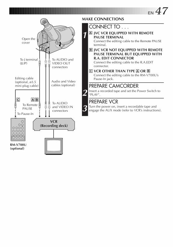
EN 47MAKE CONNECTIONS
CONNECT TO . . .
1 A JVC VCR EQUIPPED WITH REMOTEPAUSE TERMINALConnect the editing cable to the Remote PAUSEterminal.
B JVC VCR NOT EQUIPPED WITH REMOTEPAUSE TERMINAL BUT EQUIPPED WITHR.A. EDIT CONNECTORConnect the editing cable to the R.A.EDITconnector.
C VCR OTHER THAN TYPE A OR B
Connect the editing cable to the RM-V700U’sPause-In jack.
PREPARE CAMCORDER
2 Insert a recorded tape and set the Power Switch to“PLAY”.
PREPARE VCR
3 Turn the power on, insert a recordable tape andengage the AUX mode (refer to VCR’s instructions).
A BC
VCR(Recording deck)
RM-V700U(optional)
To J terminal(JLIP)
Open thecover
To AUDIO andVIDEO OUTconnectors
Audio and Videocables (optional)
Editing cable(optional, ø3.5mini-plug cable)
To AUDIOand VIDEO INconnectors
To RemotePAUSE
To Pause-In
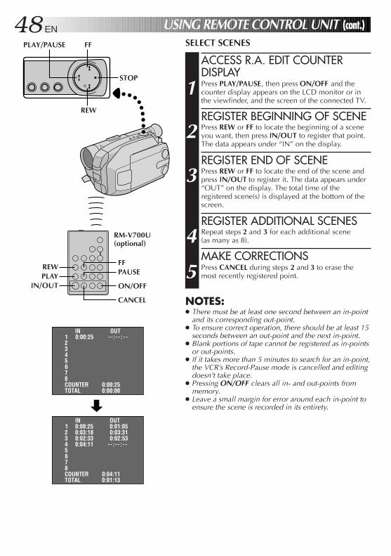
48 EN
IN OUT 1 0:00:25 -- : -- : --
2 3 4 5 6 7 8 COUNTER 0:00:25 TOTAL 0:00:00
IN OUT 1 0:00:25 0:01:05
2 0:03:18 0:03:31 3 0:02:33 0:02:53 4 0:04:11 -- : -- : -- 5 6 7 8 COUNTER 0:04:11 TOTAL 0:01:13
USING REMOTE CONTROL UNIT (cont.)SELECT SCENES
ACCESS R.A. EDIT COUNTERDISPLAY
1 Press PLAY/PAUSE, then press ON/OFF and thecounter display appears on the LCD monitor or inthe viewfinder, and the screen of the connected TV.
REGISTER BEGINNING OF SCENE
2 Press REW or FF to locate the beginning of a sceneyou want, then press IN/OUT to register that point.The data appears under “IN” on the display.
REGISTER END OF SCENE
3 Press REW or FF to locate the end of the scene andpress IN/OUT to register it. The data appears under“OUT” on the display. The total time of theregistered scene(s) is displayed at the bottom of thescreen.
REGISTER ADDITIONAL SCENES
4 Repeat steps 2 and 3 for each additional scene(as many as 8).
MAKE CORRECTIONS
5 Press CANCEL during steps 2 and 3 to erase themost recently registered point.
NOTES:● There must be at least one second between an in-point
and its corresponding out-point.● To ensure correct operation, there should be at least 15
seconds between an out-point and the next in-point.● Blank portions of tape cannot be registered as in-points
or out-points.● If it takes more than 5 minutes to search for an in-point,
the VCR’s Record-Pause mode is cancelled and editingdoesn’t take place.
● Pressing ON/OFF clears all in- and out-points frommemory.
● Leave a small margin for error around each in-point toensure the scene is recorded in its entirety.
FF
REWPLAY
IN/OUT
FFPAUSE
ON/OFF
RM-V700U(optional)
CANCEL
PLAY/PAUSE
STOP
REW
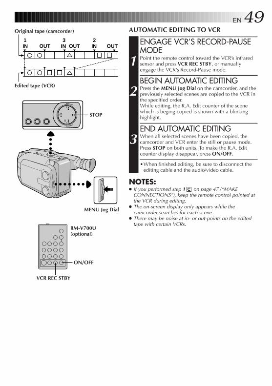
EN 49 1 3 2IN OUT IN OUT IN OUT
Original tape (camcorder)
Edited tape (VCR)
AUTOMATIC EDITING TO VCR
ENGAGE VCR’S RECORD-PAUSEMODE
1 Point the remote control toward the VCR’s infraredsensor and press VCR REC STBY, or manuallyengage the VCR’s Record-Pause mode.
BEGIN AUTOMATIC EDITING
2 Press the MENU Jog Dial on the camcorder, and thepreviously selected scenes are copied to the VCR inthe specified order.While editing, the R.A. Edit counter of the scenewhich is beging copied is shown with a blinkinghighlight.
END AUTOMATIC EDITING
3 When all selected scenes have been copied, thecamcorder and VCR enter the still or pause mode.Press STOP on both units. To make the R.A. Editcounter display disappear, press ON/OFF.
•When finished editing, be sure to disconnect theediting cable and the audio/video cable.
NOTES:● If you performed step 1 C on page 47 (“MAKE
CONNECTIONS”), keep the remote control pointed atthe VCR during editing.
● The on-screen display only appears while thecamcorder searches for each scene.
● There may be noise at in- or out-points on the editedtape with certain VCRs.
STOP
MENU Jog Dial
VCR REC STBY
ON/OFF
RM-V700U(optional)
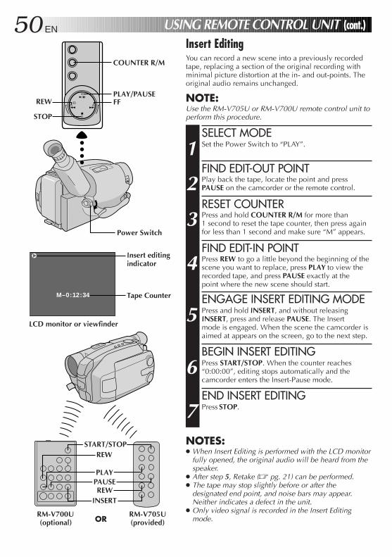
50 EN
M–0:12:34
USING REMOTE CONTROL UNIT (cont.)Insert EditingYou can record a new scene into a previously recordedtape, replacing a section of the original recording withminimal picture distortion at the in- and out-points. Theoriginal audio remains unchanged.
NOTE:Use the RM-V705U or RM-V700U remote control unit toperform this procedure.
SELECT MODE
1 Set the Power Switch to “PLAY”.
FIND EDIT-OUT POINT
2 Play back the tape, locate the point and pressPAUSE on the camcorder or the remote control.
RESET COUNTER
3 Press and hold COUNTER R/M for more than1 second to reset the tape counter, then press againfor less than 1 second and make sure “M” appears.
FIND EDIT-IN POINT
4 Press REW to go a little beyond the beginning of thescene you want to replace, press PLAY to view therecorded tape, and press PAUSE exactly at thepoint where the new scene should start.
ENGAGE INSERT EDITING MODE
5 Press and hold INSERT, and without releasingINSERT, press and release PAUSE. The Insertmode is engaged. When the scene the camcorder isaimed at appears on the screen, go to the next step.
BEGIN INSERT EDITING
6 Press START/STOP. When the counter reaches“0:00:00”, editing stops automatically and thecamcorder enters the Insert-Pause mode.
END INSERT EDITING
7 Press STOP.
NOTES:● When Insert Editing is performed with the LCD monitor
fully opened, the original audio will be heard from thespeaker.
● After step 5, Retake (Z pg. 21) can be performed.● The tape may stop slightly before or after the
designated end point, and noise bars may appear.Neither indicates a defect in the unit.
● Only video signal is recorded in the Insert Editingmode.
REW
PLAYPAUSEREW
INSERT
START/STOP
RM-V705U(provided)
RM-V700U(optional) OR
REW
COUNTER R/M
PLAY/PAUSEFF
STOP
Power Switch
Insert editingindicator
Tape Counter
LCD monitor or viewfinder
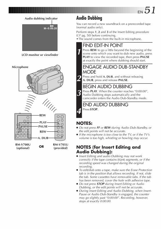
EN 51e4
M–0:05:20
Audio DubbingYou can record a new soundtrack on a prerecorded tape(normal audio only).
Perform steps 1, 2 and 3 of the Insert Editing procedure(Z pg. 50) before continuing.•The sound comes from the built-in microphone.
FIND EDIT-IN POINT
1 Press REW to go a little beyond the beginning of thescene onto which you want to dub new audio, pressPLAY to view the recorded tape, then press PAUSEat exactly the point where dubbing should start.
ENGAGE AUDIO DUB-STANDBYMODE
2 Press and hold A. DUB, and without releasingA. DUB, press and release PAUSE.
BEGIN AUDIO DUBBING
3 Press PLAY. When the counter reaches “0:00:00”,Audio Dubbing stops automatically and thecamcorder enters the Audio Dub-Standby mode.
END AUDIO DUBBING
4 Press STOP.
NOTES:● Do not press FF or REW during Audio Dub-Standby, or
the edit points will not be accurate.● If the microphone is too close to the TV, or if the TV’s
volume is too high, whistling or howling may occur.
NOTES (for Insert Editing andAudio Dubbing):● Insert Editing and audio Dubbing may not work
correctly if the tape contains blank segments, or if therecording speed was changed during the originalrecording.
● To edit/dub onto a tape, make sure the Erase Protectiontab is in the position that allows recording. If not, slidethe tab. Some cassettes have removable tabs. If the tabhas been removed, cover the hole with adhesive tape.
● Do not press STOP during Insert Editing or AudioDubbing, or the edit points will not be accurate.
● During Insert Editing and Audio Dubbing, when Insert-Pause or Audio Dub-Standby is engaged, the countermay go slightly past “0:00:00”. Recording, however,stops at exactly 0:00:00.
A. DUB
PAUSE
REW
REW
RM-V705U(provided)
RM-V700U(optional) OR
Audio dubbing indicator
LCD monitor or viewfinder
PLAY
Microphone
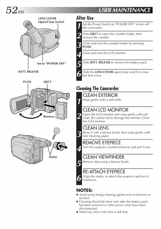
52 EN USER MAINTENANCEAfter Use
1 Set the Power Switch to “POWER OFF” to turn offthe camcorder.
2 Press EJECT to open the cassette holder, thenremove the cassette.
3 Close and lock the cassette holder by pressingPUSH.
4 Close and lock the LCD monitor.
5 Slide BATT. RELEASE to remove the battery pack.
6 Slide the LENS COVER open/close switch to closethe lens cover.
Cleaning The CamcorderCLEAN EXTERIOR
1 Wipe gently with a soft cloth.
CLEAN LCD MONITOR
2 Open the LCD monitor and wipe gently with softcloth. Be careful not to damage the monitor. Closethe LCD monitor.
CLEAN LENS
3 Blow it with a blower brush, then wipe gently withlens cleaning paper.
REMOVE EYEPIECE
4 Turn the eyepiece counterclockwise and pull it out.
CLEAN VIEWFINDER
5 Remove dust using a blower brush.
RE-ATTACH EYEPIECE
6 Align the marks, re-attach the eyepiece and turn itclockwise.
NOTES:● Avoid using strong cleaning agents such as benzine or
alcohol.● Cleaning should be done only after the battery pack
has been removed or other power units have beendisconnected.
● Mold may form if the lens is left dirty.
LENS COVEROpen/Close Switch
PUSH EJECT
Set to “POWER OFF”.
BATT. RELEASE
Marks
Remove.
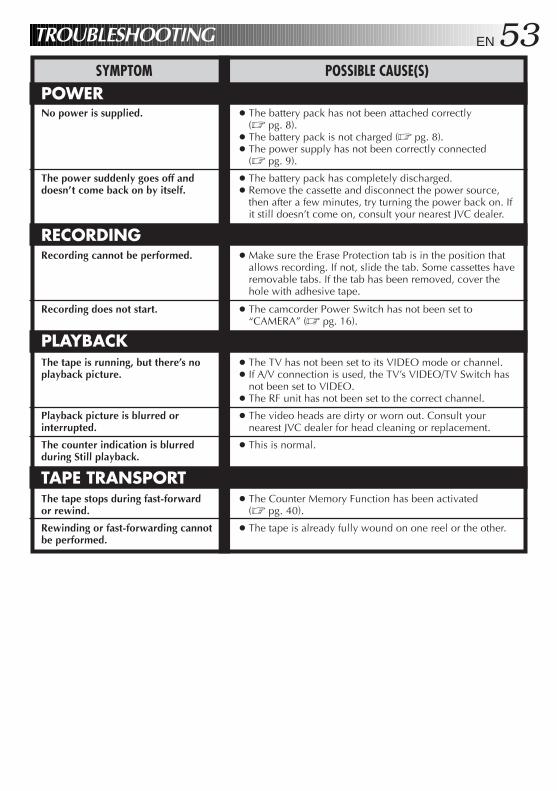
EN 53TROUBLESHOOTING
SYMPTOM POSSIBLE CAUSE(S)
POWER
RECORDING
PLAYBACK
TAPE TRANSPORT
No power is supplied.
The power suddenly goes off anddoesn’t come back on by itself.
Recording cannot be performed.
Recording does not start.
The tape is running, but there’s noplayback picture.
Playback picture is blurred orinterrupted.
The counter indication is blurredduring Still playback.
The tape stops during fast-forwardor rewind.
Rewinding or fast-forwarding cannotbe performed.
● The battery pack has not been attached correctly(Z pg. 8).
● The battery pack is not charged (Z pg. 8).● The power supply has not been correctly connected
(Z pg. 9).
● The battery pack has completely discharged.● Remove the cassette and disconnect the power source,
then after a few minutes, try turning the power back on. Ifit still doesn’t come on, consult your nearest JVC dealer.
● Make sure the Erase Protection tab is in the position thatallows recording. If not, slide the tab. Some cassettes haveremovable tabs. If the tab has been removed, cover thehole with adhesive tape.
● The camcorder Power Switch has not been set to“CAMERA” (Z pg. 16).
● The TV has not been set to its VIDEO mode or channel.● If A/V connection is used, the TV’s VIDEO/TV Switch has
not been set to VIDEO.● The RF unit has not been set to the correct channel.
● The video heads are dirty or worn out. Consult yournearest JVC dealer for head cleaning or replacement.
● This is normal.
● The Counter Memory Function has been activated(Z pg. 40).
● The tape is already fully wound on one reel or the other.
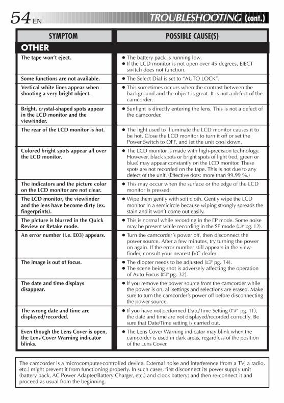
54 EN
SYMPTOM POSSIBLE CAUSE(S)
OTHER
The camcorder is a microcomputer-controlled device. External noise and interference (from a TV, a radio,etc.) might prevent it from functioning properly. In such cases, first disconnect its power supply unit(battery pack, AC Power Adapter/Battery Charger, etc.) and clock battery; and then re-connect it andproceed as usual from the beginning.
The tape won’t eject.
Some functions are not available.
Vertical white lines appear whenshooting a very bright object.
Bright, crystal-shaped spots appearin the LCD monitor and theviewfinder.
The rear of the LCD monitor is hot.
Colored bright spots appear all overthe LCD monitor.
The indicators and the picture coloron the LCD monitor are not clear.
The LCD monitor, the viewfinderand the lens have become dirty (ex.fingerprints).
The picture is blurred in the QuickReview or Retake mode.
An error number (i.e. E03) appears.
The image is out of focus.
The date and time displaysdisappear.
The wrong date and time aredisplayed/recorded.
Even though the Lens Cover is open,the Lens Cover Warning indicatorblinks.
● The battery pack is running low.● If the LCD monitor is not open over 45 degrees, EJECT
switch does not function.
● The Select Dial is set to “AUTO LOCK”.
● This sometimes occurs when the contrast between thebackground and the object is great. It is not a defect of thecamcorder.
● Sunlight is directly entering the lens. This is not a defect ofthe camcorder.
● The light used to illuminate the LCD monitor causes it tobe hot. Close the LCD monitor to turn it off or set thePower Switch to OFF, and let the unit cool down.
● The LCD monitor is made with high-precision technology.However, black spots or bright spots of light (red, green orblue) may appear constantly on the LCD monitor. Thesespots are not recorded on the tape. This is not due to anydefect of the unit. (Effective dots: more than 99.99 %.)
● This may occur when the surface or the edge of the LCDmonitor is pressed.
● Wipe them gently with soft cloth. Gently wipe the LCDmonitor in a semicircle because wiping strongly spreads thestain and it won’t come out easily.
● This is normal while recording in the EP mode. Some noisemay be present while recording in the SP mode (Z pg. 12).
● Turn the camcorder’s power off, then disconnect thepower source. After a few minutes, try turning the poweron again. If the error number still appears in the view-finder, consult your nearest JVC dealer.
● The diopter needs to be adjusted (Z pg. 14).● The scene being shot is adversely affecting the operation
of Auto Focus (Z pg. 32).
● If you remove the power source from the camcorder whilethe power is on, all settings and selections are erased. Makesure to turn the camcorder’s power off before disconnectingthe power source.
● If you have not performed Date/Time Setting (Z pg. 11),the date and time are not displayed/recorded correctly. Besure that Date/Time setting is carried out.
● The Lens Cover Warning indicator may blink when thecamcorder is used in dark areas, regardless of the positionof the Lens Cover.
TROUBLESHOOTING (cont.)
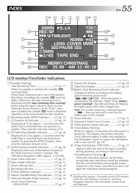
EN 55
REC SP30MIN
444
4S.LX T30
01MWB
NORM
5MIN1 4S
LENS COVERPAUSE
DEC 25.98 AM 11:45:18MERRY CHRISTMAS
TAPE END
TWILIGHT
1* 6* 72 3 4 5
^*&
*9
%
0
#$
)
(
q
8
!@
INDEX
LCD monitor/Viewfinder Indications$ Instant Title Display ............................ Z pg. 28% Date/Time Display .............................. Z pg. 22^*Battery Pack Remaining Power Indicator
Changes as follows according to the batterypack’s remaining power level:“ ”. When the power isalmost gone, the indicator “ ” blinks (batterypower warning†), then the unit shuts off. Replacethe battery pack with a fully charged one.Note: The symbol containing 3 darkened squares— — does not necessarily mean that thebattery pack is fully charged.
& Focus Indicator ................................... Z pg. 33* Exposure Control Level Counter ......... Z pg. 34( White Balance Mode Indicator ........... Z pg. 35) Clock Battery Warning
Blinks for approx. 10 seconds when the power isturned on. This display also blinks when theclock (lithium) battery is either not installed orhas discharged. Install or replace the old batterywith a new one (Z pg. 10).
q •Tape End Display: TAPE END ........... Z pg. 17Appears when the end of the tape is reachedduring playback, recording or fast-forward.
•Condensation Warning: When this indication appears, all functionsexcept tape eject and power on/off are disabled.Turn the unit off (without removing the powersource) for a few hours, and when you turn it onagain the indication should disappear.
1*Cassette Warning /Tape Remaining Time ......................... Z pg. 17When no cassette is inserted: the cassette ( )warning blinks.When Erase Protection tab is not in the positionthat allows recording: the cassette ( ) warninglights. Otherwise, the tape remaining time isdisplayed and the tape remaining time warning†blinks when the tape is about to reach its end.When the Power Switch is set to “PLAY” and atape is loaded: the cassette ( ) mark is displayedregardless of the Erase Protection tab’s position.
2 Recording Mode (SP/EP) Indicator ....... Z pg. 123, 9 Program AE Indicator ..................... Z pg. 24
Displayed at 3 for approx. 1 second when theSelect Dial is switched from one position toanother. Then only the indicator remains at 9.
3, 0 Fade/Wipe-Standby Indicator ......... Z pg. 26Displayed at 3 for approx. 2 seconds when theFade/Wipe is switched from one function toanother by pressing the EFFECT button. Thenonly the indicator remains at 0.
4 Multi-Function Control Indication ......Z pg. 26Displayed when any of the buttons located onthe Multi-Function Control is pressed. Theindication disappears within approx. 2 seconds.
5 Super LoLux Indicator ......................... Z pg. 276*Tape Length Indicator ......................... Z pg. 127 Zoom Indicator Bar ............................. Z pg. 208 Recording Indicator ............................Z pg. 16! Picture Stabilizer Indicator .................. Z pg. 21@ Interval Timer/Recording Time Indicator ... Z pg. 36# • Record–Standby Mode Indicator ......Z pg. 16
• Lens Cover Warning:LENS COVER ...................................Z pg. 17
*: Displayed for approx. 5 seconds on the LCD monitorwhen the LCD monitor is turned on, and thendisappear. However, the indications marked † arenot displayed.
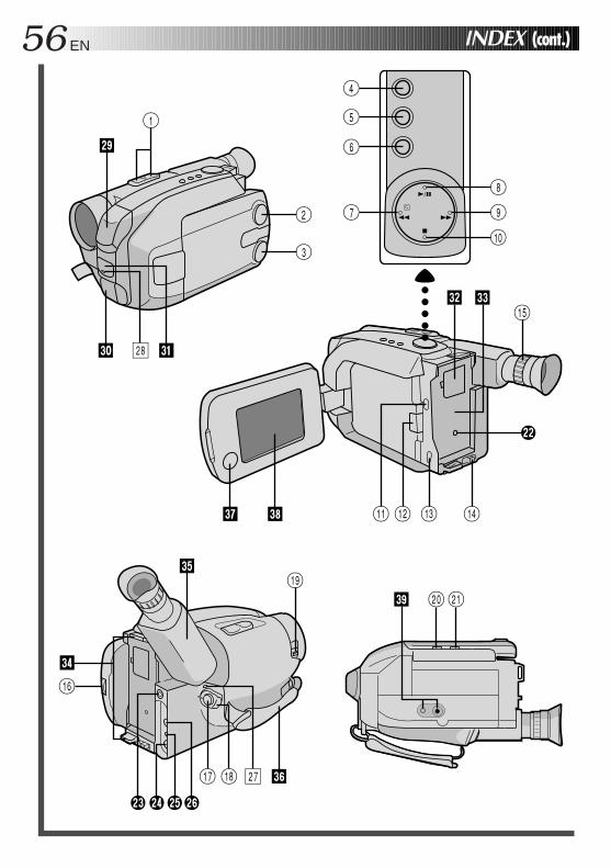
56 EN INDEX (cont.)
3
2
o
W E
p
U I
Q
1
%
() q
# $@!
w
^R
e r t y
& Y*
i
u
T
O
0
897
4
5
6
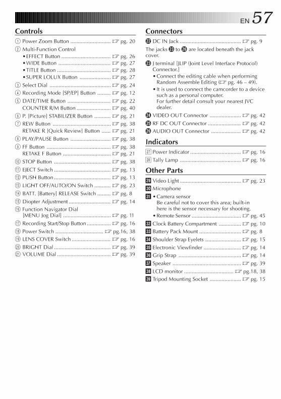
EN 57Controls1 Power Zoom Button ........................... Z pg. 20
2 Multi-Function Control•EFFECT Button ................................. Z pg. 26•WIDE Button ................................... Z pg. 27•TITLE Button .................................... Z pg. 28•SUPER LOLUX Button ..................... Z pg. 27
3 Select Dial ......................................... Z pg. 244 Recording Mode [SP/EP] Button ......... Z pg. 12
5 DATE/TIME Button ............................. Z pg. 22COUNTER R/M Button ....................... Z pg. 40
6 P. [Picture] STABILIZER Button ........... Z pg. 217 REW Button ....................................... Z pg. 38
RETAKE R [Quick Review] Button ...... Z pg. 21
8 PLAY/PAUSE Button ........................... Z pg. 38
9 FF Button ........................................... Z pg. 38RETAKE F Button ................................ Z pg. 21
0 STOP Button ...................................... Z pg. 38
! EJECT Switch ...................................... Z pg. 13@ PUSH Button ...................................... Z pg. 13
# LIGHT OFF/AUTO/ON Switch ........... Z pg. 23
$ BATT. [Battery] RELEASE Switch ......... Z pg. 8
% Diopter Adjustment ............................ Z pg. 14^ Function Navigator Dial
[MENU Jog Dial] ................................ Z pg. 11
& Recording Start/Stop Button ................ Z pg. 16
* Power Switch ................................ Z pg.16, 38( LENS COVER Switch .......................... Z pg. 16
) BRIGHT Dial ...................................... Z pg. 39q VOLUME Dial .................................... Z pg. 39
Connectorsw DC IN Jack ......................................... Z pg. 9
The jacks e to y are located beneath the jackcover.
e J terminal [JLIP (Joint Level Interface Protocol)Connector.]• Connect the editing cable when performing
Random Assemble Editing (Z pg. 46 – 49).• It is used to connect the camcorder to a device
such as a personal computer.For further detail consult your nearest JVCdealer.
r VIDEO OUT Connector ..................... Z pg. 42
t RF DC OUT Connector ...................... Z pg. 42y AUDIO OUT Connector .................... Z pg. 42
Indicatorsu Power Indicator .................................. Z pg. 16
i Tally Lamp ......................................... Z pg. 16
Other Partso Video Light ......................................... Z pg. 23p Microphone
Q • Camera sensorBe careful not to cover this area; built-inhere is the sensor necessary for shooting.
• Remote Sensor ................................. Z pg. 45
W Clock Battery Compartment ............... Z pg. 10E Battery Pack Mount ............................ Z pg. 8
R Shoulder Strap Eyelets ........................ Z pg. 15
T Electronic Viewfinder ......................... Z pg. 14Y Grip Strap .......................................... Z pg. 14
U Speaker .............................................. Z pg. 39
I LCD monitor ................................. Z pg.18, 38O Tripod Mounting Socket ..................... Z pg. 15
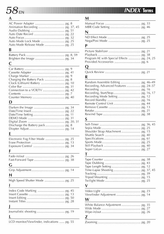
58 EN INDEX TermsAAC Power Adapter .................................. pg. 8Animation Recording .............................. pg. 37, 45Audio Dubbing ....................................... pg. 51Auto Date Record ................................... pg. 22Auto Focus .............................................. pg. 32Auto Mode Lock Mode ........................... pg. 25Auto Mode Release Mode ....................... pg. 25
BBattery Pack ............................................ pg. 8, 59Brighten the Image .................................. pg. 34
CCar Battery .............................................. pg. 9Cassette Adapter ..................................... pg. 41Charge Marker ........................................ pg. 9Charging the Battery Pack ....................... pg. 8Clock (Lithium) Battery ........................... pg. 10Color Bar ................................................ pg. 31Connection to a VCR/TV ......................... pg. 42Contents ................................................. pg. 7Counter Memory ..................................... pg. 40
DDarken the Image ................................... pg. 34Date/Time Insert ...................................... pg. 22Date/Time Setting .................................... pg. 11DEMO Mode .......................................... pg. 31Digital Zoom .......................................... pg. 20, 31Discharge the Battery pack ...................... pg. 8Diopter Adjust......................................... pg. 14
EElectronic Fog Filter Mode ...................... pg. 25Erase Protection ...................................... pg. 13Exposure Control .................................... pg. 34
FFade-in/out ............................................. pg. 26Fast-Forward Tape ................................... pg. 38
GGrip Adjustment ...................................... pg. 14
HHigh Speed Shutter Mode ....................... pg. 25
IIndex Code Marking ............................... pg. 45Insert Cassette ......................................... pg. 13Insert Editing ........................................... pg. 50Instant Titles ............................................ pg. 28
JJournalistic shooting ................................ pg. 19
LLCD monitor/Viewfinder, indications ...... pg. 55
MManual Focus ......................................... pg. 33MBR Code Setting ................................... pg. 46
NND Effect Mode ...................................... pg. 25Nega/Posi Mode ..................................... pg. 25
PPicture Stabilizer ..................................... pg. 21Playback ................................................. pg. 38Program AE with Special Effects .............. pg. 24, 25Provided Accessories .............................. pg. 6
QQuick Review ......................................... pg. 21
RRandom Assemble Editing ....................... pg. 46–49Recording, Advanced Features ................ pg. 24–37Recording ............................................... pg. 16Recording, Start/Stop ............................... pg. 16, 17Recording Mode Setting .......................... pg. 12Record-Standby ...................................... pg. 16Remote Control Unit ............................... pg. 44Remove Cassette ..................................... pg. 13Retake..................................................... pg. 21Rewind Tape ........................................... pg. 38
SSelf-Timer ............................................... pg. 36, 45Sepia Mode ............................................. pg. 25Shoulder Strap Attachment ...................... pg. 15Shuttle Search ......................................... pg. 40Specifications .......................................... pg. 61Sports Mode............................................ pg. 25Still Playback .......................................... pg. 40Super LoLux ............................................ pg. 27
TTape Counter .......................................... pg. 38Tape Dubbing ......................................... pg. 43Tape Length Setting ................................. pg. 12Time-Lapse Shooting ............................... pg. 37, 45Tracking .................................................. pg. 39Tripod Mounting ..................................... pg. 15Twilight Mode ......................................... pg. 25
VVideo Light ............................................. pg. 23Viewfinder Adjustment ............................ pg. 14
WWhite Balance Adjustment ...................... pg. 35Wide Mode ............................................. pg. 27Wipe-in/out ............................................. pg. 26
ZZooming ................................................. pg. 20
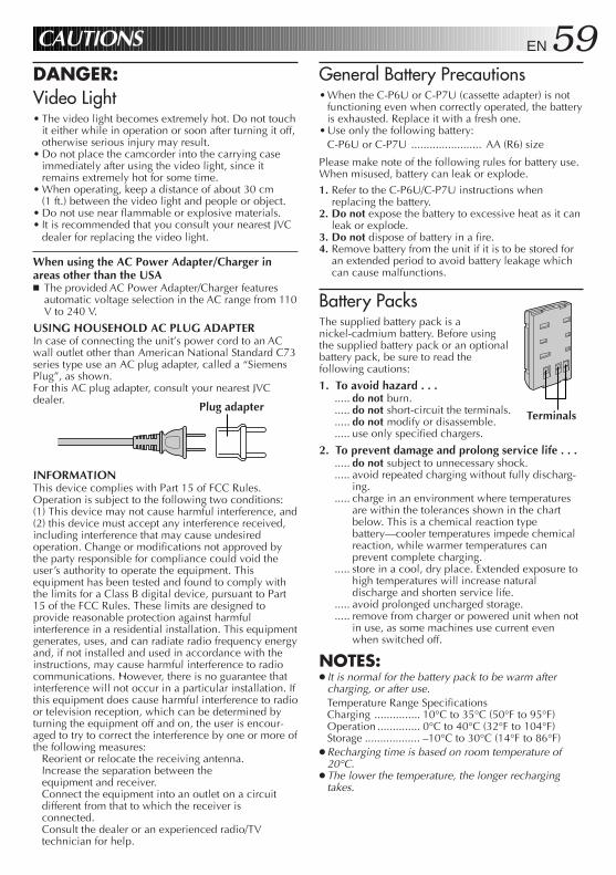
EN 59General Battery Precautions•When the C-P6U or C-P7U (cassette adapter) is not
functioning even when correctly operated, the batteryis exhausted. Replace it with a fresh one.
•Use only the following battery:C-P6U or C-P7U ....................... AA (R6) size
Please make note of the following rules for battery use.When misused, battery can leak or explode.1. Refer to the C-P6U/C-P7U instructions when
replacing the battery.2. Do not expose the battery to excessive heat as it can
leak or explode.3. Do not dispose of battery in a fire.4. Remove battery from the unit if it is to be stored for
an extended period to avoid battery leakage whichcan cause malfunctions.
Battery PacksThe supplied battery pack is anickel-cadmium battery. Before usingthe supplied battery pack or an optionalbattery pack, be sure to read thefollowing cautions:
1. To avoid hazard . . ...... do not burn...... do not short-circuit the terminals...... do not modify or disassemble...... use only specified chargers.
2. To prevent damage and prolong service life . . ...... do not subject to unnecessary shock...... avoid repeated charging without fully discharg-
ing...... charge in an environment where temperatures
are within the tolerances shown in the chartbelow. This is a chemical reaction typebattery—cooler temperatures impede chemicalreaction, while warmer temperatures canprevent complete charging.
..... store in a cool, dry place. Extended exposure tohigh temperatures will increase naturaldischarge and shorten service life.
..... avoid prolonged uncharged storage.
..... remove from charger or powered unit when notin use, as some machines use current evenwhen switched off.
NOTES:● It is normal for the battery pack to be warm after
charging, or after use.Temperature Range SpecificationsCharging ............... 10°C to 35°C (50°F to 95°F)Operation .............. 0°C to 40°C (32°F to 104°F)Storage .................. –10°C to 30°C (14°F to 86°F)
● Recharging time is based on room temperature of20°C.
● The lower the temperature, the longer rechargingtakes.
CAUTIONS
DANGER:Video Light• The video light becomes extremely hot. Do not touch
it either while in operation or soon after turning it off,otherwise serious injury may result.
• Do not place the camcorder into the carrying caseimmediately after using the video light, since itremains extremely hot for some time.
• When operating, keep a distance of about 30 cm(1 ft.) between the video light and people or object.
• Do not use near flammable or explosive materials.• It is recommended that you consult your nearest JVC
dealer for replacing the video light.
When using the AC Power Adapter/Charger inareas other than the USAn The provided AC Power Adapter/Charger features
automatic voltage selection in the AC range from 110V to 240 V.
USING HOUSEHOLD AC PLUG ADAPTERIn case of connecting the unit’s power cord to an ACwall outlet other than American National Standard C73series type use an AC plug adapter, called a “SiemensPlug”, as shown.For this AC plug adapter, consult your nearest JVCdealer.
INFORMATIONThis device complies with Part 15 of FCC Rules.Operation is subject to the following two conditions:(1) This device may not cause harmful interference, and(2) this device must accept any interference received,including interference that may cause undesiredoperation. Change or modifications not approved bythe party responsible for compliance could void theuser’s authority to operate the equipment. Thisequipment has been tested and found to comply withthe limits for a Class B digital device, pursuant to Part15 of the FCC Rules. These limits are designed toprovide reasonable protection against harmfulinterference in a residential installation. This equipmentgenerates, uses, and can radiate radio frequency energyand, if not installed and used in accordance with theinstructions, may cause harmful interference to radiocommunications. However, there is no guarantee thatinterference will not occur in a particular installation. Ifthis equipment does cause harmful interference to radioor television reception, which can be determined byturning the equipment off and on, the user is encour-aged to try to correct the interference by one or more ofthe following measures:
Reorient or relocate the receiving antenna.Increase the separation between theequipment and receiver.Connect the equipment into an outlet on a circuitdifferent from that to which the receiver isconnected.Consult the dealer or an experienced radio/TVtechnician for help.
TerminalsPlug adapter
60 EN
CassettesTo properly use and store your cassettes, be sure to readthe following cautions:
1. During use . . ...... make sure the cassette bears the VHS-C mark...... be aware that recording onto prerecorded tapes
automatically erases the previously recordedvideo and audio signals.
..... make sure the cassette is positioned properlywhen inserting.
..... do not load and unload the cassetterepeatedly without allowing the tape to run atall. This slackens the tape and can result indamage.
..... do not open the front tape cover. This exposesthe tape to fingerprints and dust.
2. Store cassettes . . ...... away from heaters or other heat sources...... out of direct sunlight...... where they won’t be subject to unnecessary
shock or vibration...... where they won’t be exposed to strong magnetic
fields (such as those generated by motors,transformers or magnets).
..... vertically, in their original cases.
Main Unit1. For safety, DO NOT . . .
..... open the camcorder’s chassis.
..... disassemble or modify the unit.
..... short-circuit the terminals of the battery pack.Keep it away from metallic objects when not inuse.
..... allow inflammables, water or metallic objects toenter the unit.
..... remove the battery pack or disconnect thepower supply while the power is on.
..... leave the battery pack attached when thecamcorder is not in use.
2. Avoid using the unit . . ...... in places subject to excessive humidity or dust...... in places subject to soot or steam such as near a
cooking stove...... in places subject to excessive shock or vibration...... near a television set...... near appliances generating strong magnetic or
electric fields (speakers, broadcasting antennas,etc.).
..... in places subject to extremely high (over 40°Cor 104°F) or extremely low (under 0°C or 32°F)temperatures.
3. DO NOT leave the unit . . ...... in places of over 50°C (122°F)...... in places where humidity is extremely low.
(below 35%) or extremely high (above 80%)...... in direct sunlight...... in a closed car in summer...... near a heater.
4. To protect the unit, DO NOT . . ...... allow it to become wet...... drop the unit or strike it against hard objects...... subject it to shock or excessive vibration during
transportation...... keep the lens directed at extremely bright
objects for long periods...... direct the eyepiece of the viewfinder at the sun...... carry it by holding the viewfinder or the LCD
monitor. Be sure to hold the main unit with bothhands or use the grip.
..... swing it excessively when using the shoulderstrap.
LCD monitor1. To prevent damage to the LCD monitor, DO
NOT . . ...... push it strongly or apply any shocks...... place the camcorder with the LCD monitor on
the bottom.
2. To prolong service life . . ...... avoid rubbing it with coarse cloth.
3. Be aware of the following phenomena for LCDmonitor use. These are not malfunctions . . .
•While using the camcorder, the surface around theLCD monitor and/or the back of the LCD monitormay heat up.
• If you leave power on for a long time, the surfacearound the LCD monitor becomes hot.
CAUTIONS (cont.)
About moisture condensation . . .● You may have observed that pouring a cold
liquid into a glass will cause drops of water toform on the glass’ outer surface. This samephenomenon occurs on the head drum of acamcorder when it is moved from a cool placeto a warm place, after heating a cold room,under extremely humid conditions or in a placedirectly subjected to the cool air from an airconditioner.
● Moisture on the head drum can cause severedamage to the video tape, and can lead tointernal damage to the camcorder itself.
Serious malfunctioning
If malfunctioning occurs, stop using the unitimmediately and consult your local JVC dealer.
EN 61SPECIFICATIONSGENERALFormat : VHS NTSC standardPower source : DC 6V Power consumption
LCD monitor off,viewfinder on : 6.0 WLCD monitor on,viewfinder off : 6.3 WLCD monitor on,viewfinder on : 7.0 WLight : 2.9 W
Signal system : NTSC-typeVideo recording system
Luminance : FM recordingColor : Converted sub-carrier
direct recordingConforms to VHSstandard
Cassette : cassetteTape speed
SP : 33.35 mm/sec.(1-5/16 ips)
EP : 11.12 mm/sec. (7/16 ips)Recording time (max.)
SP : 40 minutesEP : 120 minutes
(with TC-40 cassette)Operating temperature : 0°C to +40°C
(32°F to 104°F)Operating humidity : 35% to 80%Storage temperature : –20°C to +50°C
(–4°F to 122°F)Weight : Approx. 1000 g (2.2 lbs)Dimensions : 116 (W) x 117 (H) x(Including viewfinder) 242 (D) mm (4-5/8” x
4-5/8” x 9-9/16”)
CAMERAPick up : 1/4” format CCDLens : F1.6, f = 3.8 to 83.6 mm,
22:1 power zoom lenswith auto iris and macrocontrol, filter diameter46 mm
Viewfinder : Electronic viewfinderwith 0.5” black/whiteCRT
White balanceadjustment : Auto/Manual adjustment
LCD MONITORSize : 3” diagonally measuredLCD system : LCD/TFT active matrix
system
VIDEOOutput : 1 Vp-p, 75 ohms,
unbalanced (via VIDEOOUT connector)
AUDIOOutput : –8 dBs, 1 k-ohm
(via AUDIO OUTconnector)
Speaker : 20 mm round x 1,monaural
AC POWER ADAPTER/BATTERY CHARGER(AA-V15U)Power requirement
U.S.A. and Canada : AC 120 V`, 60 HzOther countries : AC 110 V to 240 V`,
50/60 HzPower consumption : 23 WOutput
Charge : DC 8.5 V , 1.3 AVTR : DC 6.3 V , 1.8 A
Charging system : Constant current,peak detection,timer controlled
Dimensions : 140 (W) x 42 (H) x68 (D) mm (5-9/16” x1-11/16” x 2-11/16”)
Weight : Approx. 300 g (0.71 lbs)
CASSETTE ADAPTER (C-P7U)Dimensions : 188 (W) x 25 (H) x
104 (D) mm (7-7/16” x 1”x 4-1/8”)
Weight : Approx. 240 g (0.53 lbs)Accessory : “AA (R6)”-size battery x 1
Provided Accessories ...................... Z pg. 6
Optional Accessories•Battery Packs BN-V12U, BN-V22U, BN-V25U•Car Battery Charger BH-V3U•Battery Charger BH-VC10U•Car Battery Cord AP-V7U•RF Unit RF-V5U•Compact VHS-C Cassettes TC-40/30/20•Active Carrying Bag CB-V7U•Remote Control Unit RM-V700U
Some acccessories are not available in some areas.Please consult your nearest JVC dealer for details onaccessories and their availability.
Specifications shown are for SP mode unlessotherwise indicated.E. & O. E. Design and specifications subject tochange without notice.
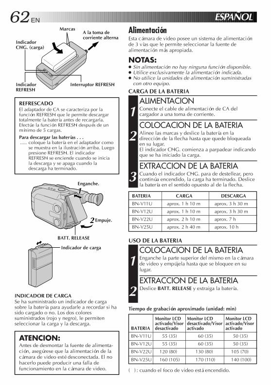
62 EN ESPAÑOL
ATENCION:Antes de desmontar la fuente de alimenta-ción, asegúrese que la alimentación de lacámara de video esté desconectada. El nohacerlo puede producir una falla defuncionamiento en la cámara de video.
INDICADOR DE CARGASe ha suministrado un indicador de cargasobre la batería para ayudarle a recordar si hasido cargado o no. Los dos coloressuministrados (rojo y negro), le permitenseleccionar la carga y la descarga.
USO DE LA BATERIA
COLOCACION DE LA BATERIA
1 Enganche la parte superior del mismo en la cámarade video y empújela hasta que se bloquee en sulugar.
EXTRACCION DE LA BATERIA
2 Deslice BATT. RELEASE y extraiga la batería.
AlimentaciónEsta cámara de video posee un sistema de alimentaciónde 3 vías que le permite seleccionar la fuente dealimentación más apropiada.
NOTAS:● Sin alimentación no hay ninguna función disponible.● Utilice exclusivamente la alimentación indicada.● No utilice la unidades de alimentación suministradas
con otro equipo.
CARGA DE LA BATERIA
ALIMENTACION
1 Conecte el cable de alimentación de CA delcargador a una toma de corriente.
COLOCACION DE LA BATERIA
2 Alinee las marcas y deslice la batería en ladirección de la flecha hasta que quede bloqueadaen su lugar.El indicador CHG. comienza a parpadear indicandoque se ha iniciado la carga.
EXTRACCION DE LA BATERIA
3 Cuando el indicador CHG. para de destellear, perocontinúa encendido, la carga ha terminado. Deslicela batería en el sentido opuesto al de la flecha.
REFRESCADOEl adaptador de CA se caracteriza por lafunción REFRESH que le permite descargartotalmente la batería antes de recargarla.Efectúe la función REFRESH después de unmínimo de 5 cargas.Para descargar las baterías . . ...... coloque la batería en el adaptador como
se muestra en la ilustración arriba. Luegopresione REFRESH. El indicadorREFRESH se enciende cuando se iniciala descarga y se apaga cuando ladescarga ha terminado.
A la toma decorriente alterna
Marcas
IndicadorCHG. (carga)
11
2
Indicador de carga
Enganche.
Empuje.
Interruptor REFRESHIndicadorREFRESH
BATT. RELEASE
BATERIA CARGA DESCARGA
BN-V11U aprox. 1 h 10 m aprox. 3 h 30 m
BN-V12U aprox. 1 h 10 m aprox. 3 h 30 m
BN-V22U aprox. 2 h 10 m aprox. 7 h
BN-V25U aprox. 2 h 40 m aprox. 10 h
Tiempo de grabación aproximado (unidad: min)
Monitor LCD Monitor LCD Monitor LCDactivado/Visor desactivado/Visor activado/Visor
BATERIA desactivado activado activado
BN-V11U 55 (35) 60 (35) 50 (35)
BN-V12U 55 (35) 60 (35) 50 (35)
BN-V22U 120 (80) 130 (80) 105 (70)
BN-V25U 160 (105) 170 (110) 140 (100)
( ) : cuando el foco de video está encendido.
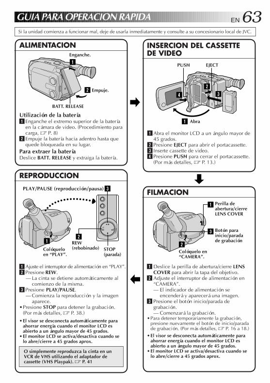
EN 63
342
1
21
3
1 Abra el monitor LCD a un ángulo mayor de45 grados.
2 Presione EJECT para abrir el portacassette.3 Inserte cassette de video.4 Presione PUSH para cerrar el portacassette.
(Por más detalles, Z P. 13.)
GUIA PARA OPERACION RAPIDA
Utilización de la batería1 Enganche el extremo superior de la batería
en la cámara de video. (Procedimiento paracarga, Z P. 8)
2 Empuje la batería hacia adentro hasta quequede bloqueada en su lugar.
Para extraer la bateríaDeslice BATT. RELEASE y extraiga la batería.
1 Ajuste el interruptor de alimentación en “PLAY”.2 Presione REW.
— La cinta se detiene automáticamente alcomienzo de la misma.
3 Presione PLAY/PAUSE.— Comienza la reproducción y la imagen
aparece.•Presione STOP para detener la grabación.
(Por más detalles, Z P. 38.)
•El visor se desconecta automáticamente paraahorrar energía cuando el monitor LCD esabierto a un ángulo mayor de 45 grados.
•El monitor LCD se activa/desactiva cuando selo abre/cierre a 45 grados aprox.
O simplemente reproduzca la cinta en unVCR de VHS utilizando el adaptador decassette (VHS Playpak). Z P. 41
2
1
Si la unidad comienza a funcionar mal, deje de usarla inmediatamente y consulte a su concesionario local de JVC.
1 Deslice la perilla de abertura/cierre LENSCOVER para abrir la tapa del objetivo.
2 Adjuste el interruptor de alimentación en“CAMERA”.— El indicador de alimentación se
encenderá y aparecerá una imagen.3 Presione el botón inicio/parada de
grabación.— Comenzará la grabación.
•Para detener temporariamente la grabación,presione nuevamente el botón de inicio/paradade grabación. (Por más detalles, Z P. 16 a 18.)
•El visor se desconecta automáticamente paraahorrar energía cuando el monitor LCD esabierto a un ángulo mayor de 45 grados.
•El monitor LCD se activa/desactiva cuando selo abre/cierre a 45 grados aprox.
3
2
1
INSERCION DEL CASSETTEDE VIDEO
ALIMENTACION
REPRODUCCION
FILMACION
Empuje.
PLAY/PAUSE (reproducción/pausa)
Colóqueloen “PLAY”.
STOP(parada)
REW(rebobinado)
Colóquelo en“CAMERA”.
Botón parainicio/paradade grabación
BATT. RELEASE
Enganche.
EJECTPUSH
Abra
Perilla deabertura/cierreLENS COVER
64 EN FOR SERVICING (Only in U.S.A.)
HOW TO LOCATE YOUR JVC SERVICE CENTER
Dear customer:In order to receive the most satisfaction from your purchase, read the instruction booklet before operating the unit. In the event that repair is necessary, or for the address nearest your location, please refer to the factory service center list below or within the Continental United States, call 1-800-252-5722 for your authorized servicer. Remember to retain your Bill of Sale for Warranty Service.
— JVC
TOLL FREE: 1-800-252-5722
107 Little Falls Road 1500 Lakes Parkway 705 Enterprise StreetFairfield, NJ 07004-2105 Lawrenceville, GA 30243-5857 Aurora, IL 60504-8135(973) 808-9279 (770) 339-2522 (630) 851-7855
5665 Corporate Avenue 10700 Hammerly Blvd., Suite 110 2969 Mapunapuna Place, Suite 101Cypress, CA 90630-4727 Houston, TX 77043-2310 Honolulu, HI 96819-2000(714) 229-8011 (713) 935-9331 (808) 833-5828
230 Eliot Street 8192 West State Road 84 890 Dubuque AvenueAshland, MA 01721-2377 Davie, FL 33324-4611 South San Francisco, CA 94080-1804(508) 881-5923 (954) 472-1960 (415) 871-2666
Sophisticated electronic products may require occasional service. Just as quality is a keyword in the engineering and production of the wide array of JVC products, service is the key to maintaining the high level performance for which JVC is world famous. The JVC service and engineering organization stands behind our products.
NATIONAL HEADQUARTERSJVC SERVICE & ENGINEERING COMPANY OF AMERICA
DIVISION OF US JVC CORP.107 Little Falls Road
Fairfield, NJ 07004-2105
Pack your JVC unit in the original carton or one of equivalent size and strength. Enclose, with the unit, a letter stating the problem or symptom that exists and also a copy of the receipt or bill of sale you received when you purchased your JVC unit. Print your home return address on the outside and the inside of the carton. Send to the appropriate JVC Factory Service Center as listed above.
If you ship the product...
To purchase accessories for your JVC product, you may contact your local JVC Dealer. Or from the 48 Continental United States call toll free: 1-800-882-2345.
ACCESSORIESCAUTION To prevent electrical shock, do not open the cabinet. No user serviceable parts inside.Refer servicing to qualified service personnel.
Don't service it yourself.
JVC SERVICE & ENGINEERINGCOMPANY OF AMERICA
DIVISION OF US JVC CORP. FACTORY SERVICE CENTER LOCATIONS
EN 65WARRANTY (Only in U.S.A.)
LIMITED WARRANTY CONSUMER VIDEO 1-90JVC COMPANY OF AMERICA warrants this product and all parts thereof, except as set forth below ONLY TO THE ORIGINAL PURCHASER AT RETAIL to be FREE FROM DEFECTIVE MATERIALS AND WORKMANSHIP from the date of original retail purchase for the period as shown below. ("The Warranty Period")
THIS LIMITED WARRANTY IS VALID ONLY IN THE FIFTY (50) UNITED STATES, THE DISTRICT OF COLUMBIA AND IN COMMONWEALTH OF PUERTO RICO.
WHAT WE WILL DO:If this product is found to be defective, JVC will repair or replace defective parts at no charge to the original owner. Such repair and replacement services shall be rendered by JVC during normal business hours at JVC authorized service centers. Parts used for replacement are warranted only for the remainder of the Warranty Period. All products and parts thereof may be brought to a JVC authorized service center on a carry-in basis except for Television sets having a screen size 25 inches and above which are covered on an in-home basis.
WHAT YOU MUST DO FOR WARRANTY SERVICE:Return your product to a JVC authorized service center with a copy of your bill of sale. For your nearest JVC authorized service center, please call toll free: (800) 252-5722.
If service is not available locally, box the product carefully, preferably in the original carton, and ship, insured, with a copy of your bill of sale plus a letter of explanation of the problem to the nearest JVC Factory Service Center, the name and location of which will be given to you by the toll-free number.
If you have any questions concerning your JVC Product, please contact our Customer Relations Department.
WHAT IS NOT COVERED:This limited warranty provided by JVC does not cover:1. Products which have been subject to abuse, accident, alteration, modification, tampering, negligence, misuse,
faulty installation, lack of reasonable care, or if repaired or serviced by anyone other than a service facility authorized by JVC to render such service, or if affixed to any attachment not provided with the products, or if the model or serial number has been altered, tampered with, defaced or removed;
2. Initial installation and installation and removal for repair;3. Operational adjustments covered in the Owner's Manual, normal maintenance, video and audio head cleaning;4. Damage that occurs in shipment, due to act of God, and cosmetic damage;5. Signal reception problems and failures due to line power surge;6. Video Pick-up Tubes/CCD Image Sensor, Cartridge, Stylus (Needle) are covered for 90 days from the date of
purchase;7. Accessories;8. Batteries (except that Rechargeable Batteries are covered for 90 days from the date of purchase);from the date
of purchase);
There are no other express warranties except as listed above.THE DURATION OF ANY IMPLIED WARRANTIES INCLUDING THE IMPLIED WARRANTY OF MERCHANTABILITY, IS LIMITED TO THE DURATION OF THE EXPRESS WARRANTY HEREIN.
JVC SHALL NOT BE LIABLE FOR THE LOSS OF USE OF THE PRODUCT, INCONVENIENCE, LOSS OR ANY OTHER DAMAGES, WHETHER DIRECT, INCIDENTAL OR CONSEQUENTIAL (INCLUDING, WITHOUT LIMITATION, DAMAGE TO TAPES, RECORDS OR DISCS) RESULTING FROM THE USE OF THIS PRODUCT, OR ARISING OUT OF ANY BREACH OF THIS WARRANTY. ALL EXPRESS AND IMPLIED WARRANTIES, INCLUDING THE WARRANTIES OF MERCHANTABILITY AND FITNESS FOR PARTICULAR PURPOSE, ARE LIMITED TO THE WARRANTY PERIOD SET FORTH ABOVE.
Some states do not allow the exclusion of incidental or consequential damages or limitations on how long an implied warranty lasts, so these limitations or exclusions may not apply to you. This warranty gives you specific legal rights and you may also have other rights which vary from state to state.
JVC COMPANY OF AMERICA 41 Slater DriveDIVISION OF US JVC CORP. Elmwood Park, New Jersey 07407
REFURBISHED PRODUCTS CARRY A SEPARATE WARRANTY, THIS WARRANTY DOES NOT APPLY. FOR DETAILS OF REFURBISHED PRODUCT WARRANTY, PLEASE REFER TO THE REFURBISHED PRODUCT WARRANTY INFORMATION PACKAGED WITH EACH REFURBISHED PRODUCT.
For customer use:Enter below the Model No. and Serial No. which is located either on the rear, bottom or side of the cabinet. Retain this information for future reference.Model No.: Serial No:
Purchase date: Name of dealer:
PARTS 1 YR LABOR 90 DAYS


GR
-AX
M300
COPYRIGHT© 1998 VICTOR COMPANY OF JAPAN, LTD. U Printed in Japan0198MSV*UN*YP
JVC COMPANY OF AMERICADIVISION OF US JVC CORP.
41 Slater Drive, Elmwood Park, N.J. 07407