Embed Size (px)
Citation preview

Compact Tunable 3 dB Hybrid and Rat-Race Couplers with Harmonics Suppression
Khair Al Shamaileh1, Mohammad Almalkawi1, Vijay Devabhaktuni1, and Nihad Dib2
1Electrical Engineering and Computer Science Department, Univ. of Toledo, Toledo, Ohio 43606, USA [email protected] [email protected]
[email protected] 2Electrical Engineering Department, Jordan Univ. of Science & Technology, Irbid, Jordan
P.O. Box 3030, Irbid 22110, Jordan [email protected]
Abstract-Miniaturized and tunable 3 dB hybrid and rat-race couplers using capacitively-loaded (C-loaded) transmission lines are designed. Couplers’ compactness has been achieved by substituting the conventional quarter wave transformers in both couplers by their equivalent C-loaded units. The tunable center frequency of the proposed couplers is realized by varying the transmission line loading capacitance. Besides the size reduction of 82% and 52% for the 3 dB hybrid and the rat-race couplers, respectively, a frequency tuning behavior ranging between 0.8-1.3 GHz is obtained. Moreover, it is proven that odd harmonics up to the 5th harmonic are efficiently suppressed. The results from two different numerical full-wave EM simulations using IE3D and HFSS verify the underlying principle. Index Terms - 3 dB hybrid coupler, capacitively-loaded transmission line, harmonics suppression, rat-race coupler.
I. INTRODUCTION
Microwave branch line and rat-race couplers are widely used in modern microwave circuits, such as power combiners and dividers, balanced mixers, image-rejection mixers, and balanced amplifiers. However, at low operating frequencies, the size of such couplers becomes rather large, and difficult to realize on microstrip printed circuit boards (PCBs). As a result, several miniaturization techniques were reported in literature to overcome their notably occupied circuit area. In [1], a compact forward-wave directional coupler was proposed using two
metal layers. The proposed coupler consisted of a pair of coupled lines and etched periodical structures on the ground plane. This approach introduces wave leakage through the ground plane and may not be an option for signal integrity constraints in PCBs crowded with other components. A reduced-size branch line coupler (BLC) was presented in [2] by incorporating a radial stub in the center of each branch. In [3], compact BLC design was introduced by adding open stubs at the center of branch lines of the traditional design. In both [2] and [3], the design is restricted by the open stub area which limits the miniaturization level and the coupler operation around short range of frequencies. Moreover, a realization of a compact BLC using quasi-fractal loaded coupled transmission-lines was presented in [4]. This technique was used to create extra cascaded coupled transmission lines within the main coupled transmission line model. In [5], two complementary miniaturization techniques were applied to reduce the size of a rat-race coupler. Firstly, the conventional microstrip sections were replaced by their diminished low impedance counterparts. Secondly, novel fractal-shaped compact resonant cells dedicated to shorten low impedance transmission line segments were implemented to further miniaturize the circuit. In [6], reduced-size rat-race coupler was presented by applying six flabelliform patches placed inside the coupler’s free area, and each flabelliform patch was connected to a high impedance transmission line outer ring via a short thin stub. However, in [5, 6], no analytical equations are derived for the design procedure. Compact dual-frequency rat-race couplers using T and π sections were
INTERNATIONAL JOURNAL OF MICROWAVE AND OPTICAL TECHNOLOGY,
VOL.7, NO.6, NOVEMBER 2012
372
IJMOT-2012-6-325 © 2012 ISRAMT
reported in [7]. In [8], a compact rat-race coupler with modified lange and T-shaped arms was presented. A modified microstrip Lange coupling structure, with a slotted ground plane and a floating-potential conductor, was used to meet the design requirements. Furthermore, a T-shaped line was utilized to further shrink the overall component size. However, design complexity is a major limitation for such approach. The objective of this paper is to present a simple and effective miniaturization technique that is applicable for transmission lines based microwave circuits. Derived equations are provided and are utilized for designing compact 3 dB hybrid and rat-race couplers. Besides the remarkable reduction in size using the proposed design approach, odd harmonics up to the 5th order of the fundamental frequency for both couplers are completely suppressed. Moreover, in contrast to open stubs, the proposed design allows center frequency tuning which, in turn, adds more flexibility and freedom to address the operation requirements. The organization of the paper is as follows: Section II describes the design equations of the conventional quarter-wave transformer, and its equivalent C-loaded transformer leading to simple analytic expressions. In Section III, design examples are presented, while IV extends the proposed designs through the representation of tunable couplers. Finally, section V concludes the paper.
II. CAPACITIVELY-LOADED TRANSMISSION LINE DESIGN
In this section, the design equations of C-loaded transmission lines are derived. Fig. 1(a) shows the conventional quarter-wave transformer with an electrical length of 900, while Fig. 1(b) represents its equivalent C-loaded unit transformer.
(a) (b) Fig. 1. (a) The conventional quarter-wave transformer; and (b) its equivalent C-loaded transformer.
The ABCD parameters for the conventional transmission line transformer are given as follows:
( ) ( )( ) ( )
0 0
0 0
-10 00 0
-1
c c
cc
0 jZ
jZ 0
cos 90 jZ sin 90A B=
C D jZ sin 90 cos 90=
.(1)
To be equivalent to the λ/4 line, the C-loaded structure should be designed to have the same ABCD parameters given in (1). The ABCD matrix of the shorted-shunt capacitor shown in Fig. 1(b) is given in the following form [9]:
1 0
1 C
A B
C D j CCM
ω==
. (2)
Furthermore, the ABCD matrix for each of the two transmission line transformers that have a characteristic impedance of Z1 and electrical length of θ1 is given by:
( ) ( )( ) ( )11 1 1
11 1 1
cos sin
sin cos
jZM
jZ
θ θθ θ−
=
. (3)
Thus, the total ABCD matrix of the whole C-loaded structure is expressed as follows:
1 1C
T
A B M MC D
M
= . (4)
This leads to the following equations:
( ) ( ) ( ) ( )2 211 1 1 1cos sin cos sinCZA ωθ θ θ θ− −= . (5.a)
and ( ) ( ) ( )2 2
11 1 1 12 sin cos sinB j Z j CZθ θ ω θ= − . (5.b)
By equating the ABCD parameters, specifically, A in (5.a) with its correspondence of the conventional quarter wave transformer given in (1), and applying some trigonometric identities, the following equation is obtained:
( )1 1
2tan 2
CZ
ωθ
= . (6)
INTERNATIONAL JOURNAL OF MICROWAVE AND OPTICAL TECHNOLOGY,
VOL.7, NO.6, NOVEMBER 2012
373
IJMOT-2012-6-325 © 2012 ISRAMT

By substituting (6) in (5.b) and using simple trigonometric identities, the transmission line impedance can be expressed by:
( )11 tan
cZZ
θ= . (7)
Finally, substituting (7) in (6) and using trigonometric identities leads to the following shunt capacitor equations:
( )( )
1
1
2tan
tan 2c
CZ
θω θ
= . (8)
By choosing θ1 such that 2θ1<900, a size reduction will be achieved. In other words, θ1 is a design parameter. Once specified, the impedance Z1 can be calculated from (7), and the capacitor value can be calculated from (8). The design methodology is fully scalable for different frequencies and impedances, and it is evident from (8) that the resonance frequency of the equivalent quarter-wavelength line structure can be shifted by altering the capacitor value C. Thus by using tunable capacitors (e.g. varactors), a tuning functionality can be added to the topology. Now, two design examples involving the use of C-loaded miniaturized BLC, and rat-race coupler will be illustrated in Section III.
III. MINIATURIZED BRANCH-LINE AND RAT-RACE COUPLERS
A. Miniaturization of a 3 dB Branch Line Coupler
The conventional BLC is a 3 dB directional coupler and has 900 phase difference between the output ports. The input power is divided equally between the coupled and through ports only. Fig. 2 shows the physical layouts for conventional and miniaturized BLC. A size reduction of 82% has been achieved using the proposed C-loaded BLC. The design procedure is based on replacing each conventional transmission line transformer (TLT) of the BLC by its C-loaded equivalent.
Considering characteristic impedance (Z0) of a 50 Ω, an FR4 substrate with a relative permittivity of 4.6, a loss tangent of 0.02, and a substrate height of 1.6 mm, with an operating frequency of 1 GHz, which lies in the L-band that supports a variety of RF applications, such as navigation systems, and Radio broadcasting, two C-loaded structures are designed as follows: First: For the 50 Ω TLT section, θ1 is arbitrarily chosen to be 200. Using (7) and (8) leads to a value of Z1 =137.37 Ω, and C1= 2.76 pF. Based on the substrate mentioned above, Z1 can be translated into a microstrip width of W1 = 0.228 mm, with a corresponding physical length of l1 = 9.58 mm. Second: For the 35.36 Ω TLT section, θ1 is chosen to be 200. Using (6) and (7) leads to a value of Z2 = 97.15 Ω, and C2= 3.9 pF. Based on the FR4 substrate, Z2 can be translated into a microstrip width of W2 = 0.717 mm, with a corresponding physical length of l2 = 9.39 mm. Fig. 3(a) illustrates the magnitude for the input port matching parameter (S11), and the isolation parameter (S41) of the C-loaded reduced-size coupler, while Fig. 3(b) shows the transmission parameters (S21), and (S31). Moreover, the resulting phases of the output S-parameters are shown in Fig. 3(c).
Fig. 2. Physical layouts of both conventional and miniaturized BLC. (Dimensions in mm). The S-parameter results are obtained using two full-wave EM simulators, namely, IE3D [10], and HFSS [11]. As shown from Fig. 3(a), the input port matching parameter and the isolation parameter are below -20 dB at the design frequency with a complete suppression of the 3rd and 5th harmonics. Furthermore, as represented in Fig. 3(b), the transmission parameters, S21 and
INTERNATIONAL JOURNAL OF MICROWAVE AND OPTICAL TECHNOLOGY,
VOL.7, NO.6, NOVEMBER 2012
374
IJMOT-2012-6-325 © 2012 ISRAMT

S31, are -3.2 dB and -3.4 dB, respectively, at 1 GHz, which are close to their theoretical values of -3 dB. Such increase in the transmission losses is mainly due to the dielectric loss of the FR-4 material expressed by a loss tangent of 0.02. Fig. 3(c) depicts the phase response of the transmission parameters of the proposed BLC, and a phase difference of 900 between the two output ports can be clearly noticed. It should be pointed out here that the discrepancies between the two EM solvers are due to the fact that both simulators solve Maxwell’s equations using two different techniques, namely, Method of Moment (MoM), and Finite Element Method (FEM), for IE3D, and HFSS, respectively.
B. Miniaturization of a Rat-Race Coupler Fig. 4 represents an outline for the C-loaded rat-race coupler compared with the conventional design. As seen in Fig. 4, each port in the conventional coupler is placed one quarter wavelength away from its adjacent one around the top half of the ring. The bottom half of the ring is three quarter wavelengths in length. The ring has a characteristic impedance of factor 1.41 compared to the port impedance (Zring = 1.41Z0). The conventional rat-race coupler has a total arc length of 1.5λ, and thus, such coupler occupies a considerable circuit area, especially at low frequencies.
(a)
(b)
(c) Fig. 3. The S-parameters of the C-loaded BLC: magnitude of (a) S11 and S41; (b) S21 and S31; and (c) phase of S21 and S31.
Fig. 4. The physical layouts of both conventional and miniaturized rat-race couplers. (Dimensions in mm) Following the guidelines presented in the previous example, each λ/4 transformer in the conventional rat-race coupler will be substituted by its equivalent C-loaded unit not only to reduce its overall size, but also to suppress the odd harmonics of the fundamental frequency. Using the same material properties used in the previous example, the C-loaded structure for the
INTERNATIONAL JOURNAL OF MICROWAVE AND OPTICAL TECHNOLOGY,
VOL.7, NO.6, NOVEMBER 2012
375
IJMOT-2012-6-325 © 2012 ISRAMT
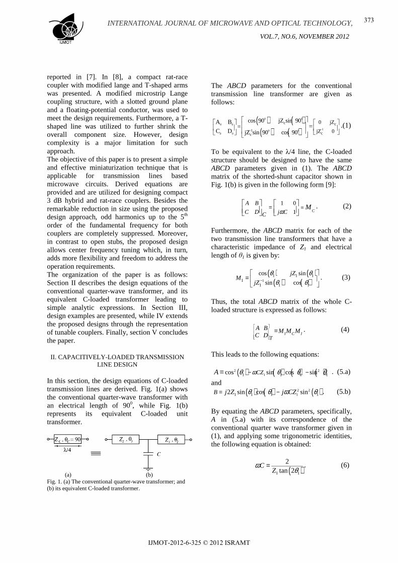
70.71 Ω TLT section is designed by choosing θ1 to be 250. Using (6) and (7) leads to a value of Z1 =151.64 Ω, and C1= 1.76 pF. Z1 can be translated into a microstrip width of W1 = 0.15 mm, with a corresponding physical length of l1 = 9.63 mm. Fig. 4 shows the physical layouts for both the conventional and miniaturized rat-race coupler. A size reduction of 52% is achieved using the C-loaded rat-race coupler. Fig. 5(a) and 5(b) depict the S-parameter magnitude of the C-loaded coupler, while Fig. 5(c) illustrates the corresponding phase response. In Fig. 5(a), the return loss at the input port is less than -30 dB and the isolation parameter (S41) is about -38 dB at 1 GHz except for the HFSS result which equals to -19 dB. The transmission parameters, S21 and S31 are -3.6 dB, and -3.2 dB, respectively, which are close to their theoretical value of -3 dB. It is clearly shown that the proposed C-loaded rat-race coupler provides harmonic suppression for the 3rd and 5th harmonics. Moreover, the phase difference in Fig. 5(c) between the two output ports is 00±20 at the design frequency.
(a)
(b)
(c)
Fig. 5. The S-parameters of the C-loaded rat-race coupler: magnitude of (a) S11 and S41; (b) S21 and S31; and (c) phase of S21 and S31.
IV. TUNABLE HYBRID AND RAT-RACE COUPLERS
As mentioned in the in the previous sections, the center frequency of the designed couplers can be tuned by changing the capacitance value derived in (8) [12]. This is practically done by replacing each capacitor with variable capacitors (varactors), and varying the capacitance by controlling the bias voltage. For demonstration, negative and positive frequency shifts between 0.8 GHz and 1.3 GHz around the center frequency (1 GHz) are accomplished as depicted in Figures 6-9 for both hybrid and rat-race couplers, by varying the obtained capacitors of the 3 dB coupler between C1: 1.4 – 4.65 pF, and
INTERNATIONAL JOURNAL OF MICROWAVE AND OPTICAL TECHNOLOGY,
VOL.7, NO.6, NOVEMBER 2012
376
IJMOT-2012-6-325 © 2012 ISRAMT
C2: 1.95–6.5 pF; and C1: 1–3 pF for the rat-race coupler.
(a)
(b)
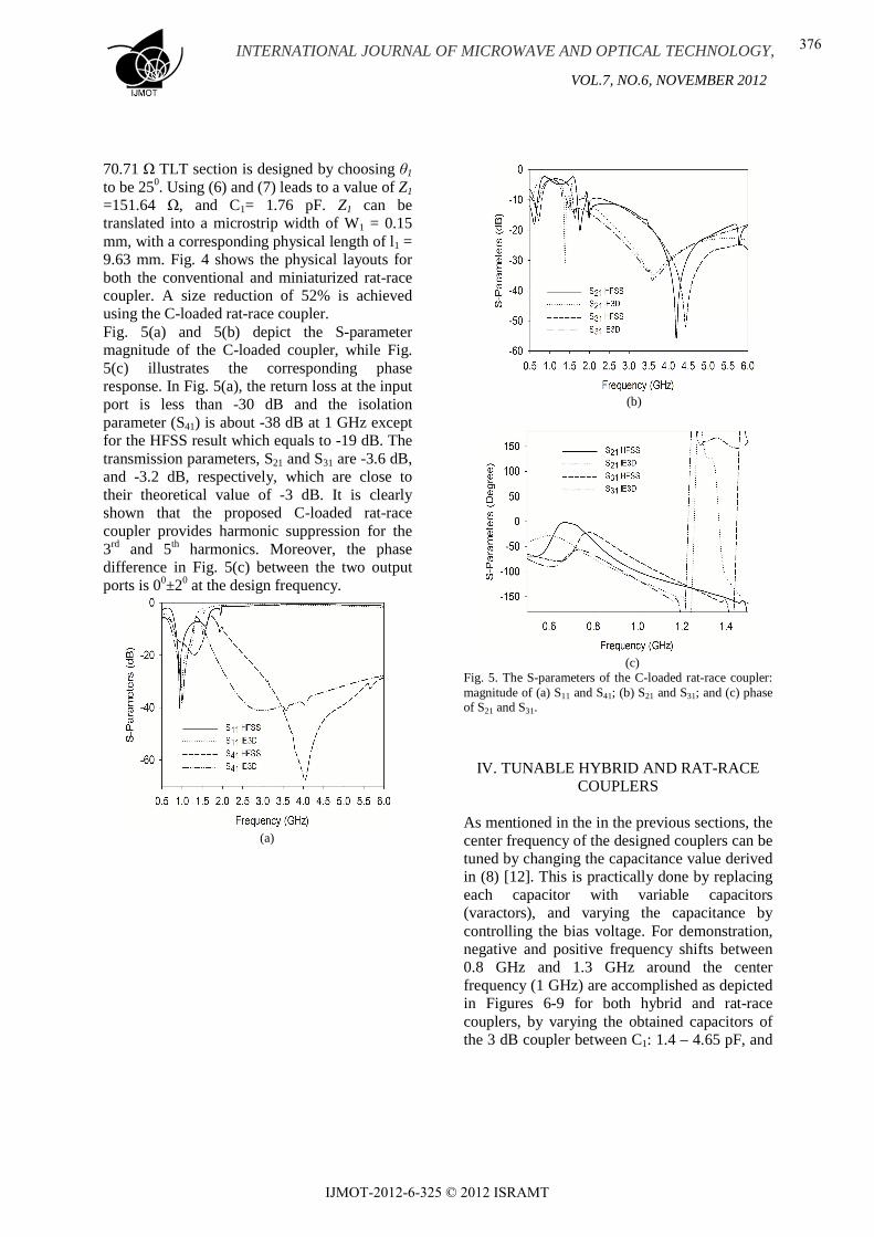
Fig. 6. The S-parameters magnitude of the C-loaded BLC tuned at 0.8 GHz: (a) S11 and S41; and (b) S21 and S31.
(a)
(b)
Fig. 7. The S-parameters magnitude of the C-loaded BLC tuned at 1.3 GHz: (a) S11 and S41; and (b) S21 and S31.
(a)
(b)
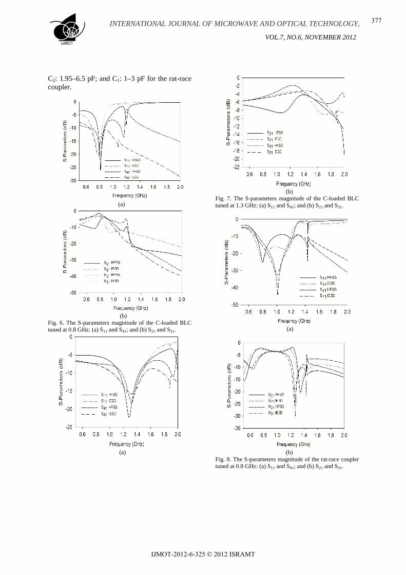
Fig. 8. The S-parameters magnitude of the rat-race coupler tuned at 0.8 GHz: (a) S11 and S41; and (b) S21 and S31.
INTERNATIONAL JOURNAL OF MICROWAVE AND OPTICAL TECHNOLOGY,
VOL.7, NO.6, NOVEMBER 2012
377
IJMOT-2012-6-325 © 2012 ISRAMT
(a)
(b)
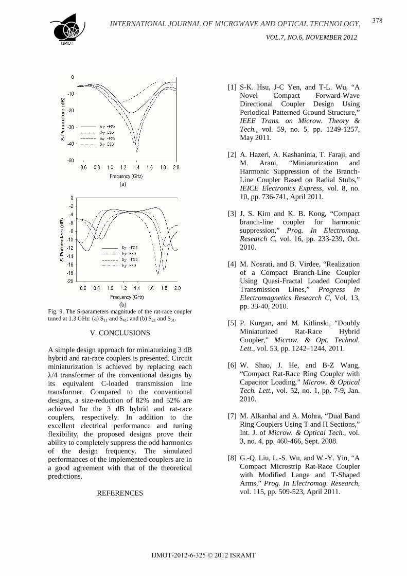
Fig. 9. The S-parameters magnitude of the rat-race coupler tuned at 1.3 GHz: (a) S11 and S41; and (b) S21 and S31.
V. CONCLUSIONS A simple design approach for miniaturizing 3 dB hybrid and rat-race couplers is presented. Circuit miniaturization is achieved by replacing each λ/4 transformer of the conventional designs by its equivalent C-loaded transmission line transformer. Compared to the conventional designs, a size-reduction of 82% and 52% are achieved for the 3 dB hybrid and rat-race couplers, respectively. In addition to the excellent electrical performance and tuning flexibility, the proposed designs prove their ability to completely suppress the odd harmonics of the design frequency. The simulated performances of the implemented couplers are in a good agreement with that of the theoretical predictions.
REFERENCES
[1] S-K. Hsu, J-C Yen, and T-L. Wu, “A
Novel Compact Forward-Wave Directional Coupler Design Using Periodical Patterned Ground Structure,” IEEE Trans. on Microw. Theory & Tech., vol. 59, no. 5, pp. 1249-1257, May 2011.
[2] A. Hazeri, A. Kashaninia, T. Faraji, and M. Arani, “Miniaturization and Harmonic Suppression of the Branch-Line Coupler Based on Radial Stubs,” IEICE Electronics Express, vol. 8, no. 10, pp. 736-741, April 2011.
[3] J. S. Kim and K. B. Kong, “Compact branch-line coupler for harmonic suppression,” Prog. In Electromag. Research C, vol. 16, pp. 233-239, Oct. 2010.
[4] M. Nosrati, and B. Virdee, “Realization of a Compact Branch-Line Coupler Using Quasi-Fractal Loaded Coupled Transmission Lines,” Progress In Electromagnetics Research C, Vol. 13, pp. 33-40, 2010.
[5] P. Kurgan, and M. Kitlinski, “Doubly Miniaturized Rat-Race Hybrid Coupler,” Microw. & Opt. Technol. Lett., vol. 53, pp. 1242–1244, 2011.
[6] W. Shao, J. He, and B-Z Wang, “Compact Rat-Race Ring Coupler with Capacitor Loading,” Microw. & Optical Tech. Lett., vol. 52, no. 1, pp. 7-9, Jan. 2010.
[7] M. Alkanhal and A. Mohra, “Dual Band Ring Couplers Using T and П Sections,” Int. J. of Microw. & Optical Tech., vol. 3, no. 4, pp. 460-466, Sept. 2008.
[8] G.-Q. Liu, L.-S. Wu, and W.-Y. Yin, “A Compact Microstrip Rat-Race Coupler with Modified Lange and T-Shaped Arms,” Prog. In Electromag. Research, vol. 115, pp. 509-523, April 2011.
INTERNATIONAL JOURNAL OF MICROWAVE AND OPTICAL TECHNOLOGY,
VOL.7, NO.6, NOVEMBER 2012
378
IJMOT-2012-6-325 © 2012 ISRAMT

[9] D. M. Pozar, Microwave Engineering,
New York: John Wiley & Sons, 3rd ed., 2005.
[10] Mentor Graphics PCB Design Software, 2006. IE3D: Method of Moment (MoM) based full-wave electromagnetics simulator, v. 14.2.
[11] ANSYS High Frequency Structure Simulator (HFSS), Ansys, Inc., Canonsburg, PA, 2011.
[12] E. Lourandakis, M. Schmidtt, A. Leidlt, S. Seitzt, and R. Weigel, “A Tunable and Reduced Size Power Divider Using Ferroelectric Thin-Film Varactors,” Microw. Symp. Digest, IEEE MTT-S Int., pp. 967-970, June 2008.
INTERNATIONAL JOURNAL OF MICROWAVE AND OPTICAL TECHNOLOGY,
VOL.7, NO.6, NOVEMBER 2012
379
IJMOT-2012-6-325 © 2012 ISRAMT