Embed Size (px)
Citation preview
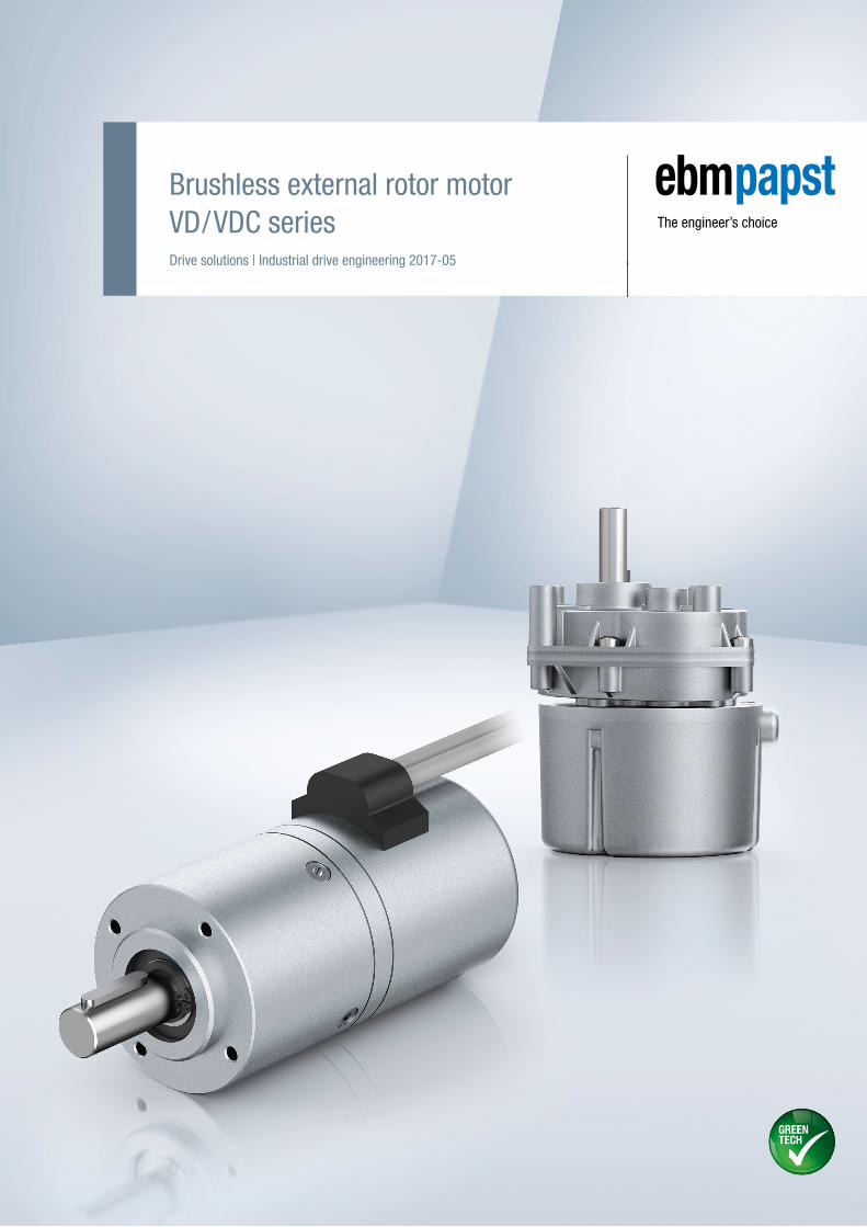
Brushless external rotor motorVD/VDC seriesDrive solutions | Industrial drive engineering 2017-05

Modular drive systems. Motors with integrated logic and power electronics – optional gearhead.

3
2017
-05-
b
Contents.
Information About ebm-papst 4Overview of VD/VDC motors 7
VD/VDC motorsInformation about VD/VDC motors 10Definitions for VD/VDC motors 12VD-25.07-K1 14VD-35.06-K1 16VD-43.10-K1 18VD-54.14-K1 20VD-49.15-K1 22VDC-43.10-K3 24VDC-54.14-K3 26VDC-49.15-K3 28VDC-49.15-K4 30
Control electronicsVTD-XX.XX-K3 (speed) 34VTD-XX.XX-K4S (position) 36VTD-60.13-K5SB (CANopen) 38
GearheadsInformation about gearheads 42NoiselessPlus 63 (planetary gearhead) 44 Performax® 63 (planetary gearhead) 46Performax®Plus 63 (planetary gearhead) 48EtaCrown® 75 (crown gearhead) 50EtaCrown®Plus 63 (crown gearhead) 52Compactline 90 (spur gearhead) 54Compactline 91 (spur gearhead) 56Compactline 92 (spur gearhead) 58Flatline 85 (spur gearhead) 60
Accessories Commissioning tools 64Accessories 66
Standards and guidelines 68Operating factor, lifetime, efficiency 70ebm-papst around the world 73
Info
rmat
ion
VD/V
DC m
otor
sCo
ntro
l ele
ctro
nics
Gear
head
sAc
cess
orie
sGe
nera
l inf
orm
atio
neb
m-p
apst
aro
und
the
wor
ld

4
2017
-05-
b
About ebm-papst.
As technological leader for ventilation and drive engineering, ebm-papst is in demand
as an engineering partner in many industries. With over 15,000 different products, we
provide the right solution for just about any challenge. Our fans and drives are reliable,
quiet and energy-efficient.
Six reasons that make us the ideal partner:
Our systems expertise.
You want the best solution for every project. The inter relationships
between ventilation and drive engineering must thus be considered
as a whole. And that’s what we do – with motor technology that sets
standards, sophisticated electronics and aerodynamic designs –
all from a single source and perfectly matched. These system solu-
tions release unique synergies worldwide. And in particular – they
relieve you of a lot of work, so that you can concentrate on your core
competency.
The ebm-papst spirit of invention.
In addition to our wide range of products, we are always able to
develop customized solutions for you. A diversified team of
600 engineers and technicians works at our three locations in
Germany: Mulfingen, Landshut and St. Georgen. Contact us to
discuss your next project.
Our lead in technology.
As pioneer and trail-blazer for developing highly efficient EC tech-
nology, we are way ahead of other motor manufacturers. Almost
all our products are also available with GreenTech EC technology.
The list of benefits is long: higher efficiency, main tenance-free, longer
service life, sound reduction, intelligent control characteristics and
unrivalled energy efficiency with savings of up to 80 % compared to
conventional AC technology. Let our technology be your competitive
advantage as you lead in your industry.
Closeness to our customers.
ebm-papst has 25 production locations worldwide (including facilities
in Germany, China and the USA), together with 49 sales offices, each of
which has a dense network of sales representatives. You will always
have a local contact, someone who speaks your language and knows
your market.
Our standard of quality.
Of course you can rely on the highest standards of quality with our
products. Our quality management is uncompromising, at every step
in every process. This is underscored by our certification according
to international standards including DIN EN ISO 9001, TS declaration
of conformity and DIN EN ISO 14001.
Our sustainable approach.
Assuming responsibility for the environment, for our employees and
for society is an integral part of our corporate philosophy. We develop
products with an eye to maximum environmental compatibility,
in particular resource-preserving production methods. We promote
environmental awareness among our young staff and are actively
involved in sports, culture and education. That’s what makes us a
leading company – and an ideal partner for you.
2
ebm15060_Toolbox_Unternehmenstext_2/1-Seite_en_20170123.indd 1 10.02.17 11:47

5
2017
-05-
b
1963 Elektrobau Mulfingen GmbH & Co. KG founded by Gerhard Sturm and Heinz Ziehl.
1965 Development of the first compact fan in the field of EC-/DC-technology.
1966 The ebm-papst success story started to take off with the release of the new 68 motor.
1972 The first foreign subsidiary was founded in Sweden.
1988 Gerhard Sturm receives the German Cross of Merit.
1990 The sixty millionth external rotor fan was produced.
1992 Acquisition of PAPST Motoren GmbH in St. Georgen.
1997 Purchase of the Landshut plant (mvl).
2003 Change of name to ebm-papst.
2007 Introduction of the gearhead “EtaCrown®”.
2010 GreenTech – our symbol for energy-efficiency and resource conservation.
2012 Introduction of a new generation control electronics (K4) for BLDC motors.
2013 ebm-papst acquires the gear specialist, Zeitlauf, and wins the German Sustainability Award.
2014 Launch of the BLDC intenal rotor motor, ECI 80.
2015 Introduction of the overload-capable planetary gear “Optimax 63”.
2016 Expansion of the electronic production plant, St. Georgen Hagenmoos.
Our success story to becoming market leader and technological innovator.
About ebm-papst.
As technological leader for ventilation and drive engineering, ebm-papst is in demand
as an engineering partner in many industries. With over 15,000 different products, we
provide the right solution for just about any challenge. Our fans and drives are reliable,
quiet and energy-efficient.
Six reasons that make us the ideal partner:
Our systems expertise.
You want the best solution for every project. The inter relationships
between ventilation and drive engineering must thus be considered
as a whole. And that’s what we do – with motor technology that sets
standards, sophisticated electronics and aerodynamic designs –
all from a single source and perfectly matched. These system solu-
tions release unique synergies worldwide. And in particular – they
relieve you of a lot of work, so that you can concentrate on your core
competency.
The ebm-papst spirit of invention.
In addition to our wide range of products, we are always able to
develop customized solutions for you. A diversified team of
600 engineers and technicians works at our three locations in
Germany: Mulfingen, Landshut and St. Georgen. Contact us to
discuss your next project.
Our lead in technology.
As pioneer and trail-blazer for developing highly efficient EC tech-
nology, we are way ahead of other motor manufacturers. Almost
all our products are also available with GreenTech EC technology.
The list of benefits is long: higher efficiency, main tenance-free, longer
service life, sound reduction, intelligent control characteristics and
unrivalled energy efficiency with savings of up to 80 % compared to
conventional AC technology. Let our technology be your competitive
advantage as you lead in your industry.
Closeness to our customers.
ebm-papst has 25 production locations worldwide (including facilities
in Germany, China and the USA), together with 49 sales offices, each of
which has a dense network of sales representatives. You will always
have a local contact, someone who speaks your language and knows
your market.
Our standard of quality.
Of course you can rely on the highest standards of quality with our
products. Our quality management is uncompromising, at every step
in every process. This is underscored by our certification according
to international standards including DIN EN ISO 9001, TS declaration
of conformity and DIN EN ISO 14001.
Our sustainable approach.
Assuming responsibility for the environment, for our employees and
for society is an integral part of our corporate philosophy. We develop
products with an eye to maximum environmental compatibility,
in particular resource-preserving production methods. We promote
environmental awareness among our young staff and are actively
involved in sports, culture and education. That’s what makes us a
leading company – and an ideal partner for you.
2
ebm15060_Toolbox_Unternehmenstext_2/1-Seite_en_20170123.indd 1 10.02.17 11:47
Info
rmat
ion
VD/V
DC m
otor
sCo
ntro
l ele
ctro
nics
Gear
head
sAc
cess
orie
sGe
nera
l inf
orm
atio
neb
m-p
apst
aro
und
the
wor
ld
6
2017
-05-
b

7
2017
-05-
b
Overview of VD/VDC motors.
With our preferred type products, we offer a selection of motors and gear motors which are available and ready to ship within 48 hours. Preferred type products can be ordered with a maximum order quantity of 20 products per order.
With standard type products, we refer to a wide range of motors and gear motors which can be ordered using the stated order numbers with standard delivery times.
Further products for your project requirements are available on request. These products are generally available but cannot be ordered by means of an allocated material number. We reserve the right to make changes to the necessary order numbers after technical and economic evaluation of the requirement.
Brushless externalrotor motorsVD/VDC
VD-2
5.07
(p. 1
4)
VD-3
5.06
(p. 1
6)
VD-4
3.10
(p. 1
8)
VD-5
4.14
(p. 2
0)
VD-4
9.15
(p. 2
2)
VDC-
43.1
0 (p
. 24)
VDC-
54.1
4 (p
. 26)
VDC-
49.1
5 (p
. 28)
VDC-
49.1
5 (p
. 30)
VDC-
49.1
5 (p
. 30)
UN V DC 24 24 24 24 24 24 24 24 24 48
MN mNm 8 20 54 150 235 45 130 150 235 300
P W 5 8 21 57 110 19 47.6 63 100 125
nN rpm 6 000 3 700 3 700 3 700 4 500 4 000 3 500 4 000 4 000 4 000
l mm 23.6 29.3 40.8 43.3 52 40 42 52 52 52
d mm 32 44 52.8 68.4 63 52.8 68.3 63 63 63
Control electronics (integrated) (from page 10)
K1 (Hall sensor system) � � � � �
K3 (speed) � � �
K4 (position) � �
Control electronics (external) (from page 34)
VTD-XX.XX-K3 � � � � �
VTD-XX.XX-K4S � �
VTD-60.13-K5 SB � � �
Gearheads (from page 42)
NoiselessPlus 63 (planetary gearhead) (p. 44) �
Performax® 63 (planetary gearhead) (p. 46) � � �
Performax®Plus 63 (planetary gearhead) (p. 48) �
EtaCrown® 75 (crown gearhead) (p. 50) � � �
EtaCrown®Plus 63 (crown gearhead) (p. 52) � � �
Compactline 90 (spur gearhead) (p. 54) � �
Compactline 91 (spur gearhead) (p. 56) � � � � � � � �
Compactline 92 (spur gearhead) (p. 58) � �
Flatline 85 (spur gearhead) (p. 60) � � � � � �
Subject to alterations � Standard type � Preferred type: ready to ship in 48 hours
Info
rmat
ion
VD/V
DC m
otor
sCo
ntro
l ele
ctro
nics
Gear
head
sAc
cess
orie
sGe
nera
l inf
orm
atio
neb
m-p
apst
aro
und
the
wor
ld

8
2017
-05-
b

9
2017
-05-
b
VD/VDC motors.
VD-25.07-K1 14
VD-35.06-K1 16
VD-43.10-K1 18
VD-54.14-K1 20
VD-49.15-K1 22
VDC-43.10-K3 24
VDC-54.14-K3 26
VDC-49.15-K3 28
VDC-49.15-K4 30
Info
rmat
ion
VD/V
DC m
otor
sCo
ntro
l ele
ctro
nics
Gear
head
sAc
cess
orie
sGe
nera
l inf
orm
atio
neb
m-p
apst
aro
und
the
wor
ld

10
2017
-05-
b
Information for VD/VDC motors.
Key figures
– 3-phase, electronically commutated external rotor motor
– Output range between 5 and 125 watts
– High power density realized in a compact design
– Very quiet operation across the entire speed range
– High overload capacity
– Very high power density
– Rigid speed / torque curve
– Extremely wide speed control range
– Robust housing and bearings
– Protection class IP 54 as per EN 60 034-5: up to IP 65
– Various motor types which can be combined with planetary,
crown and spur gearheads
Approvals
– Support with the accreditation of products in different economic
areas and markets
– As an experienced and competent partner we would be happy to
support you
– Possible approvals include CE, CCC, UL, CSA, EAC
– Additional approvals on request
Logic and power electronics
Winding
Magnet

11
2017
-05-
b
The data in this catalog contain product specifications, but are not
a guarantee of particular properties.
All information is based on the measuring conditions mentioned
below. Operation of motors using reference electronics at an
ambient temperature of max. 40°C when attached (thermally
conductive) to a free-standing steel plate of the following size:
Steel plate 105 x 105 x 10 mm
The nominal operating point is the basis for the electromagnetic
design of the motor from the point of view of the maximum possible
continuous output of the motor and is specified by the nominal val-
ues described here.
The values mentioned are typical values for the design in question
and are also subject to the tolerances included in the specifications
or drawings. Unless otherwise stated, the supplements and safety
notes contained in the relevant operating and assembly instructions
must be kept at all times. Subject to availability and technical alter-
ations.
Nominal output power PN [W]
The output power which the motor can produce continuously; it is
calculated from nominal torque and nominal speed. For the electro-
magnetic design of the motor the determination of the nominal
operating point is based on the fact that the nominal output power
is close the maximum output power of the motor.
Nominal voltage UBN , UN , UB [V DC]
The DC voltage (i.e. DC voltage range) that is applied to the
commutation electronics as a system supply voltage. All nominal
values listed in the technical tables of the individual motors refer
to this voltage. Motor applications are, however, not restricted to
this voltage.
Nominal speed nN [rpm]
The speed at which the motor may be operated continuously while
delivering nominal torque at an ambient temperature of 40°C and
nominal output torque. It is an operating point on the max. motor
curve based on an ideal electronics with negligible losses.
Nominal torque MN [mNm]
The torque that the motor can deliver continuously at an ambient
temperature of 40°C and nominal speed.
The illustrated curves are idealized representations based on the
figures in the tables.
Nominal current IBN
The current that is drawn from the system supply when the motor
delivers nominal torque at nominal speed.
Speed at no-load operation nL [rpm]
The speed that takes effect at the nominal voltage and with
unloaded motor. The theoretical possible speed at no-load operation
can, in some cases, be limited by the mechanical ceiling speed.
No-load current IBL [A]
Is established with nominal voltage and unloaded motor; is largely
influenced by the bearing friction. For drive systems that have a
separate supply for power and logic, the no-load current is called IL.
This no-load current is the sum of the power supply (IZK) and the
low-power logic supply (IB).
Permanent stall torque MBn0 [mNm]
Is the maximum permissible torque with which the motor may be
permanently loaded when the rotor is locked.
Permissible eff. continuous stall current In0eff [A]
Is the maximum permissible current which at a stalled motor is
allowed to flow into the motor lead as an effective value.
Info
rmat
ion
VD/V
DC m
otor
sCo
ntro
l ele
ctro
nics
Gear
head
sAc
cess
orie
sGe
nera
l inf
orm
atio
neb
m-p
apst
aro
und
the
wor
ld
6 000
5 000
4 000
3 000
2 000
1 000
0
20,0
16,7
13,3
10,0
6,7
3,3
0
MN
0 100 200 300 400 500 600 700 800
MMax
100
90
80
70
60
50
40
30
20
10
0
Effic
ienc
y
[%
]
Torque M [mNm]
Curr
ent I
[A]
Continuous operation
Spee
d n
[min
-1]
12
2017
-05-
b
Continuous stall power PBn0 [W]
Is an approximate value for the voltage-independent maximum
permitted output (P=U x I) that can be taken from the DC voltage
source in holding status.
Permissible peak torque short-term Mmax [mNm]
Is the torque which the motor can usually deliver in a short time.
Permissible peak current, motor lead Imax [A]
Is the current that must flow in to the motor lead as a peak value to
achieve the short-time peak torque.
Induced voltage Uimax [V/1 000 rpm]
Maximum value of the induced voltage between two motor leads
at 1 000 rpm. It is a dimension for the electromagnetic utilization
of the motor.
Connection resistance Rv [Ohm]
The winding resistance that is measured at 20°C between any two
of three winding terminations.
Connection inductance LV [mH]
The average inductance that is measured at 20°C between any two
of three winding terminations using a sinusoidal wave measuring
frequency of 1 kHz.
Rotor moment of inertia JR [kgm2x10-6]
The mass moment of inertia of the rotor and necessary dimension
for the dynamic characteristics of the motor.
Protection class
Information on the protection class; it describes protection against
foreign particles (Point 1) and water (Point 2).
Permissible ambient temperature range TU [°C]
Defines the minimum and maximum permissible ambient tempera-
ture to which the mentioned performance values apply when the
motor is in operation. The permissible winding temperature in the
motor (115°C for insulation Class E, as per EN 60 034-1) </1125
should not be exceeded.
Weight [kg]
Weight of the delivered unit without additional units or packaging.
Max. shaft load Fradial/Faxial [N]
The permissible forces are divided into radial and axial load values.
They are based on the maximum permissible values for the motor
bearing during operation at normal rating and a defined service life
expectancy L10.
Service life L10
The values for the L10 service life specified in conjunction with the
permitted bearing loads have been calculated to DIN ISO 281. In
addition to the specified values, this calculation is based on opera-
tion of the motor at nominal conditions (nominal torque, nominal
speed) and an ambient temperature of max. 40°C. Therefore, the
service life information is explicitly not a guarantee of service life,
but strictly a theoretical quality figure.
Max. reverse voltage [V DC]
When the braking function is activated and when the set value step
change is negative, the motor operates in controlled braking mode.
In this operating state, the large part of the braking energy is fed
back to the intermediate circuit until the max. reverse voltage is
reached and the electronics prevent a further increase beyond this
value by chopped braking. This behavior should be given special
consideration when selecting the system supply.
Set value input
Speed setting via an analogue interface for DC voltage.
Depending on the drive design, the set speed can be configured
in a range from 0 ... nmax, where the minimum possible speed value
(with limited control quality) is about 0 rpm (sine commutation)
or approx. 50 to 100 rpm (block commutation). (Relevant only for
drives with integrated operating electronics).
Recommended speed range [rpm]
Speed control range within which the speed control accuracy
stipulated in the system specification is complied with.
Definitions for VD/VDC motors.
13
2017
-05-
b
MA Starting torque MBr Braking
tA Acceleration time tBr Braking time
ML Load torque tSt Standstill time
tB Load period
Meff = MA2 � tA + ML2 � tB + MBr2 � tBr
tA + tB + tBr + tSt
ML = MN �100
tr
Starting torque [mNm]
Is the torque that can be delivered over a short time when the motor
is started based on the electromagnetic motor characteristics and
the set current limitation.
Effective torque Meff [mNm]
For cycle operation (e.g. “S5” operating mode – intermittent duty
with the effect of the startup losses and the losses due to electrical
braking on the heating), the effective torque corresponding to con-
tinuous operation (“S1” operating mode) is determined according to
the following formula:
At an ambient temperature of 40°C this effective torque must not
be greater than the nominal torque MN listed in the catalog for
the selected motor. For intermittent operation (operating mode S3
with tr = relative on period) the following permissible load moment
applies:
System selection
When selecting a motor and operating for a drive system, consider-
ation should be given to the fact that the values permitted for the
motor should not be exceeded by the electronics. Likewise, the
relationship shown in the commutation sequences between the
sequence of Hall signals and the corresponding switching times and
switching states of the output stage at the phase supply lines must
be observed in order to attain optimum operation of the motor.
Please contact the manufacturer if the products are operated or
stored under non standard environmental conditions.
Info
rmat
ion
VD/V
DC m
otor
sCo
ntro
l ele
ctro
nics
Gear
head
sAc
cess
orie
sGe
nera
l inf
orm
atio
neb
m-p
apst
aro
und
the
wor
ld

14
2017
-05-
b
– 3-phase external rotor motor with EC technology
– Basic motor with electronic module K1 for operation on
external control electronics
– Very good synchronization characteristics
– Long lifetime by using precision ball bearings
– Insulation class E
– Electrical connection via socket directly on the circuit board
– Alternative windings / motor part sets on request
VD motor.VD-25.07-K1
1) Nominal data, see table
Characteristic curve
VD-25.07-K1-B01 (at 25°C)
Nominal data
Type VD-25.07-K1-B01
Nominal voltage (UN) V DC 24
Nominal speed (nN)* rpm 6 000
Nominal torque (MN)* mNm 8.00
Nominal current (IN)* A 0.40
Nominal output power (PN)* W 5.00
Starting torque (Mmax) mNm 40.0
Permissible peak current (Imax)** A 1.80
Speed at no-load operation (nL) rpm 8 500
No-load current (IL) A 0.095
Recommended speed control range rpm 300 ... 8 500
Rotor moment of inertia (JR) kgm2 x10–6 4.30
Motor constant (KE) mVs/rad 26.6
Connection resistance (RV) Ω 14.8
Connection inductance (LV) mH 8.00
Overload protection To be implemented via the control electronics
Permissible ambient temperature range (TU) °C 0 ... +40
Weight kg 0.055
Order no. IP 00 937 2507 000
Subject to alterations * At TU max. 40°C** Permissible time for peak current: max. 1 sec. – to be repeated only after complete cool down
Torque M [mNm]
Curr
ent I
[A]
0 2 4 6 8 10 12
Continuous operation
MN MMax
12 500
10 000
7 500
5 000
2 500
0
1,0
0,8
0,6
0,4
0,2
0
Spee
d n
[min
-1]
100
90
80
70
60
50
40
30
20
10
0
Effic
ienc
y
[%
]
15
2017
-05-
b
1
2
7
8
3 5
4 6
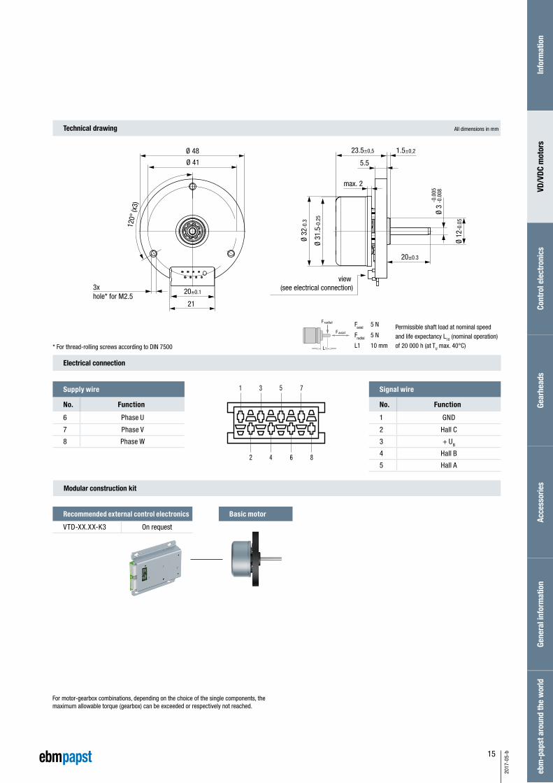
Technical drawing All dimensions in mm
Electrical connection
Signal wire
No. Function
1 GND
2 Hall C
3 + UB
4 Hall B
5 Hall A
Supply wire
No. Function
6 Phase U
7 Phase V
8 Phase W
Basic motor
Modular construction kit
For motor-gearbox combinations, depending on the choice of the single components, the maximum allowable torque (gearbox) can be exceeded or respectively not reached.
Faxial 5 N
Fradial 5 N
L1 10 mm
Faxial
Fradial
L1* For thread-rolling screws according to DIN 7500
Recommended external control electronics
VTD-XX.XX-K3 On request
Info
rmat
ion
VD/V
DC m
otor
sCo
ntro
l ele
ctro
nics
Gear
head
sAc
cess
orie
sGe
nera
l inf
orm
atio
neb
m-p
apst
aro
und
the
wor
ld
20±0.3
23.5±0,5
max. 2
20±0.1
Ø 48
5.5
1.5±0,2
Ø 12
-0.0
5
3x hole* for M2.5
Ø 41
120°
(x3)
21
Ø 31
.5-0
.25
Ø 32
-0.3
Ø 3
-0.0
08-0
.005
view (see electrical connection)
Permissible shaft load at nominal speedand life expectancy L10 (nominal operation) of 20 000 h (at TU max. 40°C)

16
2017
-05-
b
– 3-phase external rotor motor with EC technology
– Basic motor with electronic module K1 for operation on
external control electronics
– Very good synchronization characteristics
– Long lifetime by using precision ball bearings
– Insulation class E
– Electrical connection via the circuit board edge plug
– Alternative windings / motor part sets on request
VD motor.VD-35.06-K1
Nominal data
Type VD-35.06-K1-B01 VD-35.06-K1-B00
Nominal voltage (UN) V DC 24
Nominal speed (nN)* rpm 7 500 3 700
Nominal torque (MN)* mNm 20.0 20.0
Nominal current (IN)* A 1.25 0.80
Nominal output power (PN)* W 16.0 8.00
Starting torque (Mmax) mNm 69.0
Permissible peak current (Imax)** A 4.00 2.50
Speed at no-load operation (nL) rpm 11 000 7 100
No-load current (IL) A 0.25 0.16
Recommended speed control range rpm 300 ... 11 000 300 ... 7 100
Rotor moment of inertia (JR) kgm2 x10–6 16.0
Motor constant (KE) mVs/rad 20.9 33.6
Connection resistance (RV) Ω 3.70 9.40
Connection inductance (LV) mH 2.50 6.40
Overload protection To be implemented via the control electronics
Permissible ambient temperature range (TU) °C 0 ... +40
Weight kg 0.12
Order no. IP 00 937 3506 000 937 3506 010
Subject to alterations * At TU max. 40°C** Permissible time for peak current: max. 1 sec. – to be repeated only after complete cool down
Characteristic curve
1) Nominal data, see table1) Nominal data, see table
VD-35.06-K1-B01 (at 25°C) VD-35.06-K1-B00 (at 25°C)
12 500
10 000
7 500
5 000
2 500
0
4,0
3,2
2,4
1,6
0,8
0
MN
0 5 10 15 20 25 30
MMax
Torque M [mNm]
Curr
ent I
[A]
Continuous operation
Spee
d n
[min
-1]
Effic
ienc
y
[%
]
100
90
80
70
60
50
40
30
20
10
0
12 500
10 000
7 500
5 000
2 500
0
4,0
3,2
2,4
1,6
0,8
0
MN
0 5 10 15 20 25 30
MMax
100
90
80
70
60
50
40
30
20
10
0
Torque M [mNm]
Curr
ent I
[A]
Continuous operation
Spee
d n
[min
-1]
Effic
ienc
y
[%
]
17
2017
-05-
b
12345678
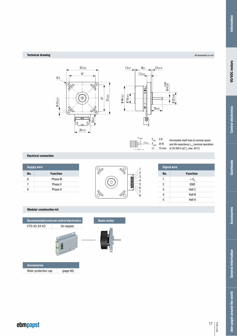
Technical drawing
Electrical connection
Modular construction kit
All dimensions in mm
Permissible shaft load at nominal speedand life expectancy L10 (nominal operation) of 20 000 h (at TU max. 40°C)
Faxial 5 N
Fradial 20 N
L1 10 mm
Faxial
Fradial
L1
Basic motor
Signal wire
No. Function
1 + UB
2 GND
3 Hall C
4 Hall B
5 Hall A
Supply wire
No. Function
6 Phase W
7 Phase V
8 Phase U
Recommended external control electronics
VTD-XX.XX-K3 On request
Info
rmat
ion
VD/V
DC m
otor
sCo
ntro
l ele
ctro
nics
Gear
head
sAc
cess
orie
sGe
nera
l inf
orm
atio
neb
m-p
apst
aro
und
the
wor
ld
Accessories
Rotor protection cap (page 66)
2.5+0.1528±11.2±0.1
47
Ø 4.
5+0.
3
28-0.15
47
20±0
.5
57±0
.5
R 5
57±0.5
20±0.5
Ø 44
+0.2
Ø 18
+0.5
7.2±0.3
Ø 22
-0.0
5
Ø 4-
0.01
-0.0
05
18
2017
-05-
b
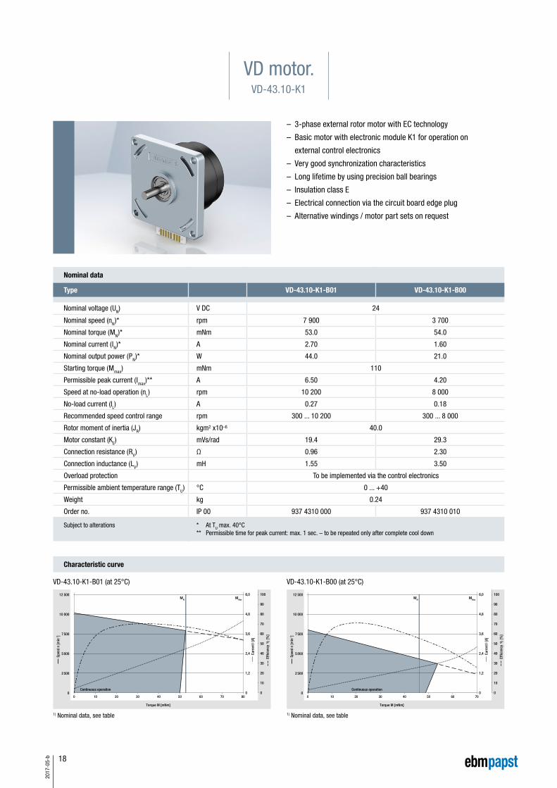
– 3-phase external rotor motor with EC technology
– Basic motor with electronic module K1 for operation on
external control electronics
– Very good synchronization characteristics
– Long lifetime by using precision ball bearings
– Insulation class E
– Electrical connection via the circuit board edge plug
– Alternative windings / motor part sets on request
VD motor.VD-43.10-K1
Nominal data
Type VD-43.10-K1-B01 VD-43.10-K1-B00
Nominal voltage (UN) V DC 24
Nominal speed (nN)* rpm 7 900 3 700
Nominal torque (MN)* mNm 53.0 54.0
Nominal current (IN)* A 2.70 1.60
Nominal output power (PN)* W 44.0 21.0
Starting torque (Mmax) mNm 110
Permissible peak current (Imax)** A 6.50 4.20
Speed at no-load operation (nL) rpm 10 200 8 000
No-load current (IL) A 0.27 0.18
Recommended speed control range rpm 300 ... 10 200 300 ... 8 000
Rotor moment of inertia (JR) kgm2 x10–6 40.0
Motor constant (KE) mVs/rad 19.4 29.3
Connection resistance (RV) Ω 0.96 2.30
Connection inductance (LV) mH 1.55 3.50
Overload protection To be implemented via the control electronics
Permissible ambient temperature range (TU) °C 0 ... +40
Weight kg 0.24
Order no. IP 00 937 4310 000 937 4310 010
Subject to alterations * At TU max. 40°C** Permissible time for peak current: max. 1 sec. – to be repeated only after complete cool down
Characteristic curve
1) Nominal data, see table1) Nominal data, see table
VD-43.10-K1-B01 (at 25°C) VD-43.10-K1-B00 (at 25°C)
12 500
10 000
7 500
5 000
2 500
0
6,0
4,8
3,6
2,4
1,2
0
MN
0 10 20 30 40 50 60 70 80
100
90
80
70
60
50
40
30
20
10
0
MMax
Effic
ienc
y
[%
]
Torque M [mNm]
Curr
ent I
[A]
Continuous operation
Spee
d n
[min
-1]
12 500
10 000
7 500
5 000
2 500
0
6,0
4,8
3,6
2,4
1,2
0
MN
0 10 20 30 40 50 60 70
MMax
100
90
80
70
60
50
40
30
20
10
0
Effic
ienc
y
[%
]
Torque M [mNm]
Curr
ent I
[A]
Continuous operation
Spee
d n
[min
-1]

19
2017
-05-
b
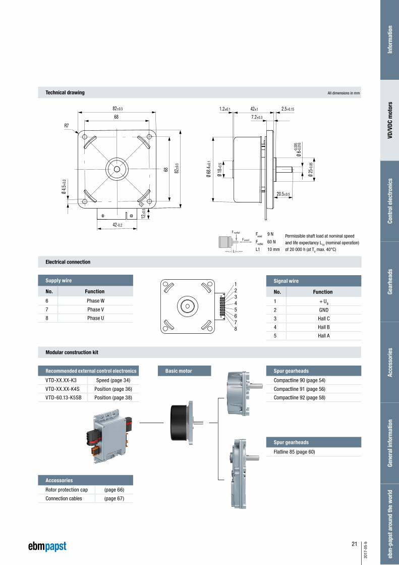
12345678
Modular construction kit
Faxial 9 N
Fradial 35 N
L1 10 mm
Faxial
Fradial
L1
Signal wire
No. Function
1 + UB
2 GND
3 Hall C
4 Hall B
5 Hall A
Supply wire
No. Function
6 Phase W
7 Phase V
8 Phase U
Basic motorRecommended external control electronics
VTD-XX.XX-K3 On request
VTD-60.13-K5SB On request
Spur gearheads
Compactline 91 (page 56)
Technical drawing
Electrical connection
All dimensions in mm
Info
rmat
ion
VD/V
DC m
otor
sCo
ntro
l ele
ctro
nics
Gear
head
sAc
cess
orie
sGe
nera
l inf
orm
atio
neb
m-p
apst
aro
und
the
wor
ld
Accessories
rotor protection cap (page 66)
Connection cables (page 67)
1.2±0.1 39.5+1 2.5+0.15
7.2±0.3
Ø 5-
0.01
-0.0
05
Ø 25
-0.0
5
Ø 18
+0.
5
Ø 52
,8±
0.1
65±0
.5
56
56
65±0.5
R 4.5
Ø 4.
5+0.
3
19±0
.5
28-0.15
20±0.5
Permissible shaft load at nominal speedand life expectancy L10 (nominal operation) of 20 000 h (at TU max. 40°C)

20
2017
-05-
b
– 3-phase external rotor motor with EC technology
– Basic motor with electronic module K1 for operation on
external control electronics
– Very good synchronization characteristics
– Long lifetime by using precision ball bearings
– Insulation class E
– Electrical connection via the circuit board edge plug
VD motor.VD-54.14-K1
Nominal data
Type VD-54.14-K1-B01 VD-54.14-K1-B00
Nominal voltage (UN) V DC 24
Nominal speed (nN)* rpm 5 600 3 700
Nominal torque (MN)* mNm 150
Nominal current (IN)* A 5.10 3.60
Nominal output power (PN)* W 88.0 57.0
Starting torque (Mmax) mNm 400
Permissible peak current (Imax)** A 15.0 10.0
Speed at no-load operation (nL) rpm 7 100 5 200
No-load current (IL) A 0.41 0.26
Recommended speed control range rpm 300 ... 7 100 300 ... 5 200
Rotor moment of inertia (JR) kgm2 x10–6 145
Motor constant (KE) mVs/rad 29.2 41.8
Connection resistance (RV) Ω 0.49 0.96
Connection inductance (LV) mH 1.00 2.00
Overload protection To be implemented via the control electronics
Permissible ambient temperature range (TU) °C 0 ... +40
Weight kg 0.52
Order no. IP 00 937 5414 000 937 5414 010
Subject to alterations * At TU max. 40°C** Permissible time for peak current: max. 1 sec. – to be repeated only after complete cool down
Characteristic curve
1) Nominal data, see table1) Nominal data, see table
VD-54.14-K1-B01 (at 25°C) VD-54.14-K1-B00 (at 25°C)
MN
8 000
7 000
6 000
5 000
4 000
3 000
2 000
1 000
0
10,0
8,75
7,50
6,25
5,00
3,75
2,50
1,25
050 100 150 200
MMax
100
90
80
70
60
50
40
30
20
10
0
Effic
ienc
y
[%
]
Torque M [mNm]
Curr
ent I
[A]
Continuous operation
Spee
d n
[min
-1]
8 000
7 000
6 000
5 000
4 000
3 000
2 000
1 000
0
10,0
8,75
7,50
6,25
5,00
3,75
2,50
1,25
0
MN
0 50 100 150 200
MMax
100
90
80
70
60
50
40
30
20
10
0
Effic
ienc
y
[%
]
Torque M [mNm]
Curr
ent I
[A]
Continuous operation
Spee
d n
[min
-1]
21
2017
-05-
b
12345678
Faxial 9 N
Fradial 60 N
L1 10 mm
Signal wire
No. Function
1 + UB
2 GND
3 Hall C
4 Hall B
5 Hall A
Supply wire
No. Function
6 Phase W
7 Phase V
8 Phase U
Recommended external control electronics
VTD-XX.XX-K3 Speed (page 34)
VTD-XX.XX-K4S Position (page 36)
VTD-60.13-K5SB Position (page 38)
Spur gearheads
Compactline 90 (page 54)
Compactline 91 (page 56)
Compactline 92 (page 58)
Spur gearheads
Flatline 85 (page 60)
Modular construction kit
Basic motor
Technical drawing
Electrical connection
All dimensions in mm
Faxial
Fradial
L1
Info
rmat
ion
VD/V
DC m
otor
sCo
ntro
l ele
ctro
nics
Gear
head
sAc
cess
orie
sGe
nera
l inf
orm
atio
neb
m-p
apst
aro
und
the
wor
ld
Accessories
Rotor protection cap (page 66)
Connection cables (page 67)
82±0
.5
12±0
.5
68
82±0.5
68
42-0.2
42±1
7.2±0.3
2.5+0.15
R7
1.2±0.1
Ø 18
+0.5
Ø 25
-0.0
5
Ø 4.
5+0.
3
-0.0
05Ø
6-0.
010
Ø 68
.4±0
.1
20.5±0.5
Permissible shaft load at nominal speedand life expectancy L10 (nominal operation) of 20 000 h (at TU max. 40°C)
22
2017
-05-
b
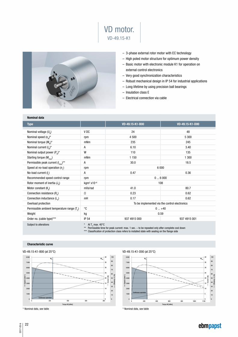
– 3-phase external rotor motor with EC technology
– High poled motor structure for optimum power density
– Basic motor with electronic module K1 for operation on
external control electronics
– Very good synchronization characteristics
– Robust mechanical design in IP 54 for industrial applications
– Long lifetime by using precision ball bearings
– Insulation class E
– Electrical connection via cable
VD motor.VD-49.15-K1
Nominal data
Type VD-49.15-K1-B00 VD-49.15-K1-D00
Nominal voltage (UN) V DC 24 48
Nominal speed (nN)* rpm 4 500 5 300
Nominal torque (MN)* mNm 235 245
Nominal current (IN)* A 6.10 3.40
Nominal output power (PN)* W 110 135
Starting torque (Mmax) mNm 1 150 1 300
Permissible peak current (Imax)** A 30.0 18.5
Speed at no-load operation (nL) rpm 6 000
No-load current (IL) A 0.47 0.36
Recommended speed control range rpm 0 ... 6 000
Rotor moment of inertia (JR) kgm2 x10–6 108
Motor constant (KE) mVs/rad 41.0 80.7
Connection resistance (RV) Ω 0.23 0.62
Connection inductance (LV) mH 0.17 0.62
Overload protection To be implemented via the control electronics
Permissible ambient temperature range (TU) °C 0 ... +40
Weight kg 0.59
Order no. (cable type)*** IP 54 937 4915 000 937 4915 001
Subject to alterations * At TU max. 40°C** Permissible time for peak current: max. 1 sec. – to be repeated only after complete cool down*** Classification of protection class refers to installed state with sealing on the flange side
Characteristic curve
1) Nominal data, see table1) Nominal data, see table
VD-49.15-K1-B00 (at 25°C) VD-49.15-K1-D00 (at 25°C)
8 000
7 000
6 000
5 000
4 000
3 000
2 000
1 000
0
40
35
30
25
20
15
10
5
0
MN
0 200 400 600 800
MMax
100
90
80
70
60
50
40
30
20
10
0
Effic
ienc
y
[%
]
Torque M [mNm]
Curr
ent I
[A]
Continuous operation
Spee
d n
[min
-1]
8 000
7 000
6 000
5 000
4 000
3 000
2 000
1 000
0
40
35
30
25
20
15
10
5
0
MN
0 200 400 600 800 1000 1150
MMax
100
90
80
70
60
50
40
30
20
10
0
Effic
ienc
y
[%
]
Torque M [mNm]
Curr
ent I
[A]
Continuous operation
Spee
d n
[min
-1]

23
2017
-05-
b
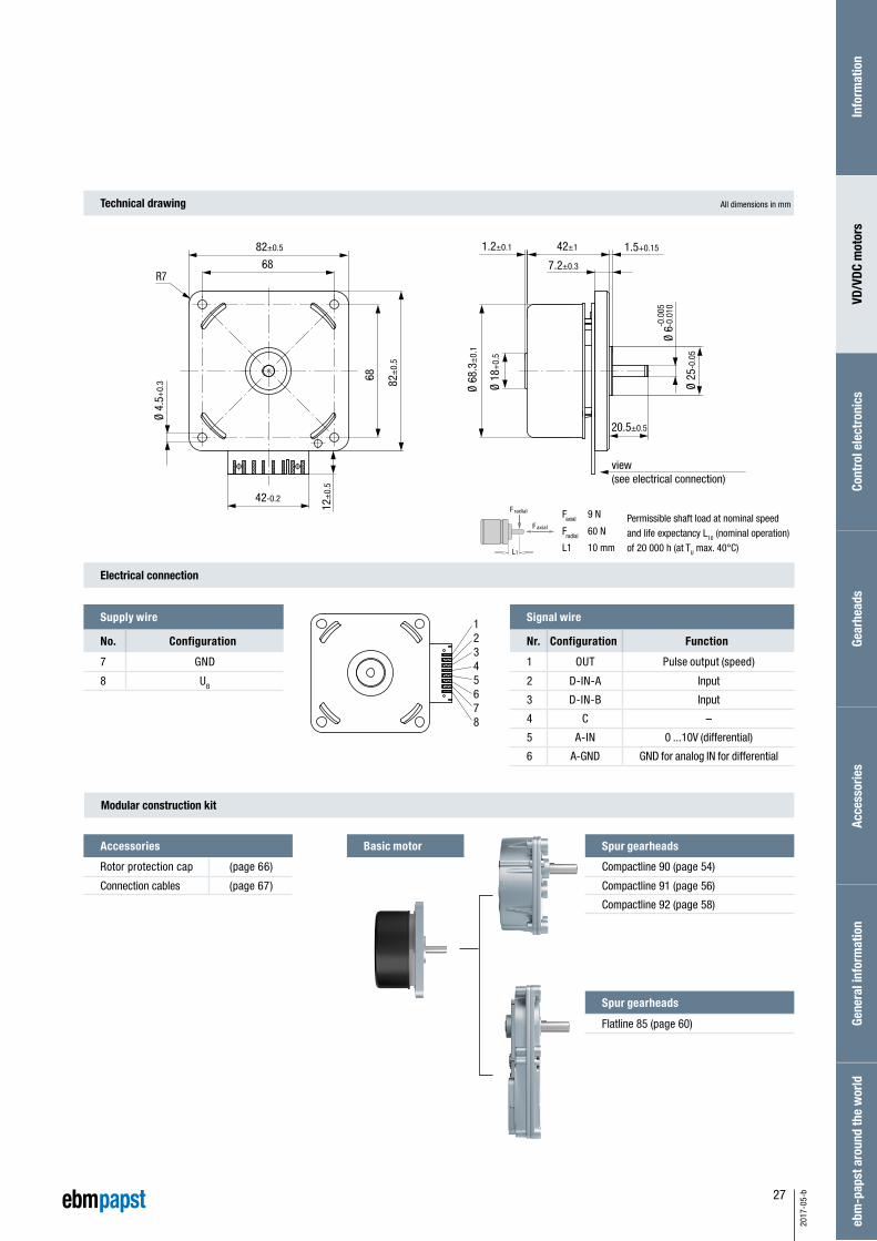
Faxial 20 N
Fradial 60 N
L1 10 mm
Signal wire
No. Color Function
1 – –
2 red +12 V
3 white Hall B
4 green Hall A
5 – –
6 – –
7 black GND
8 gray Hall C
Supply wire
No. Color Function
1 yellow Phase W
2 violet Phase V
3 brown Phase U
Planetary gearheads
NoiselessPlus 63 (page 44)
Performax® 63 (page 46)
Performax®Plus 63 (page 48)
Crown gearheads
EtaCrown® 75 (page 50)
EtaCrown®Plus 63 (page 52)
Spur gearheads
Compactline 91 (page 56)
Flatline 85 (page 60)
* For thread-rolling screws according to DIN 7500
Recommended external control electronics
VTD-XX.XX-K3 Speed (page 34)
VTD-XX.XX-K4S Position (page 36)
VTD-60.13-K5SB Position (page 38)
Modular construction kit
Basic motor
Technical drawing
Electrical connection
All dimensions in mm
Faxial
Fradial
L1
1
2
3
6
7
8
1
2
3
4
5
Molex Stecker Nr. 39-03-6035
Molex Stecker Nr. 39-01-2085
Molex plug no. 39-03-6035
Molex plug no. 39-01-2085
Info
rmat
ion
VD/V
DC m
otor
sCo
ntro
l ele
ctro
nics
Gear
head
sAc
cess
orie
sGe
nera
l inf
orm
atio
neb
m-p
apst
aro
und
the
wor
ld
52±0.5 20±0.3
2,5±0.1
500±10
24±0.530±5
Ø 25
h8
Ø 8+
0.00
6+
0.01
0
24±0.2
Ø 40
Ø 50
Ø 63±0.2
3x12
0°
44.6
5±0.
5
R 35
6x hole* M4
29.9
Permissible shaft load at nominal speedand life expectancy L10 (nominal operation) of 20 000 h (at TU max. 40°C)

24
2017
-05-
b
– 3-phase external rotor motor with EC technology
– Drive with completely integrated K3 operation and control electronics
– Integrated speed control function
– Interface with analog and digital control inputs
– Very good synchronization characteristics
– Long lifetime by using precision ball bearings
– Electrical connection via the circuit board edge plug
VDC motor.VDC-43.10-K3
Nominal data
Type VDC-43.10-K3-B01 VDC-43.10-K3-B00
Nominal voltage (UN) V DC 24
Nominal speed (nN)* min–1 6 800 4 000
Nominal torque (MN)* mNm 45
Nominal current (IN)* A 2.00 1.25
Nominal output power (PN)* W 32.0 18.8
Starting torque (Mmax) mNm 67
Speed at no-load operation (nL) min–1 10 200 4 100
No-load current (IL) A 0.40 0.14
Recommended speed control range min–1 300 ... 10 000 300 ... 4 000
Rotor moment of inertia (JR) kgm2 x10–6 40
Overload protection integrated
Permissible ambient temperature range (TU) °C 0 ... +40
Weight kg 0.24
Order no. IP 00 937 4310 600 937 4310 610
Subject to alterations * At TU max. 40°C
Characteristic curve
1) Nominal data, see table1) Nominal data, see table
VDC-43.10-K3-B01 (at 25°C) VDC-43.10-K3-B00 (at 25°C)
12 500
10 000
7 500
5 000
2 500
0
7,0
5,6
4,2
2,8
1,4
0
MN
0 10 20 30 40 50 60
MMax
100
90
80
70
60
50
40
30
20
10
0
Effic
ienc
y
[%
]
Torque M [mNm]
Curr
ent I
[A]
Continuous operation
Spee
d n
[min
-1]
12 500
10 000
7 500
5 000
2 500
0
7,0
5,6
4,2
2,8
1,4
0
MN
0 10 20 30 40 50
MMax
100
90
80
70
60
50
40
30
20
10
0
Effic
ienc
y
[%
]
Torque M [mNm]
Curr
ent I
[A]
Continuous operation
Spee
d n
[min
-1]

25
2017
-05-
b
12345678
Faxial 9 N
Fradial 35 N
L1 10 mm
Signal wire
Nr. Configuration Function
1 OUT Pulse output (speed)
2 D-IN-A Input
3 D-IN-B Input
4 C –
5 A-IN 0 ...10V (differential)
6 A-GND GND for analog IN for differential
Supply wire
No. Configuration
7 GND
8 UB
Spur gearheads
Compactline 91 (page 56)
Modular construction kit
Basic motor
Technical drawing
Electrical connection
All dimensions in mm
Faxial
Fradial
L1
Info
rmat
ion
VD/V
DC m
otor
sCo
ntro
l ele
ctro
nics
Gear
head
sAc
cess
orie
sGe
nera
l inf
orm
atio
neb
m-p
apst
aro
und
the
wor
ldAccessories
Connection cables (page 67)
view (see electrical connection)
65±0
.5
56
56
65±0.5
R 4.5
Ø 4.
5+0.
3
Ø 6-
0.00
9
28+0.15
1.2±0.1 40±1 2.5+0.15
7.2±0.3
Ø 25
-0.05
Ø 18
+0.
5
Ø 52
.8±
0.1
10.5
±0.
5
+0.
006
20±0.5
Capacitor
Permissible shaft load at nominal speedand life expectancy L10 (nominal operation) of 20 000 h (at TU max. 40°C)

26
2017
-05-
b
– 3-phase external rotor motor with EC technology
– Drive with completely integrated K3 operation and control electronics
– Integrated speed control function
– Interface with analog and digital control inputs
– Very good synchronization characteristics
– Long lifetime by using precision ball bearings
– Electrical connection via the circuit board edge plug
VDC motor.VDC-54.14-K3
Nominal data
Type VDC-54.14-K3-B01 VDC-54.14-K3-B00
Nominal voltage (UN) V DC 24
Nominal speed (nN)* min–1 6 000 3 500
Nominal torque (MN)* mNm 100 150
Nominal current (IN)* A 3.60 2.80
Nominal output power (PN)* W 62.8 47.6
Starting torque (Mmax) mNm 120
Speed at no-load operation (nL) min–1 8 000 4 000
No-load current (IL) A 0.51 0.21
Recommended speed control range min–1 300 ... 8 000 300 ... 4 000
Rotor moment of inertia (JR) kgm2 x10–6 145
Overload protection integrated
Permissible ambient temperature range (TU) °C 0 ... +40
Weight kg 0.52
Order no. IP 00 937 5414 622 937 5414 620
Subject to alterations * At TU max. 40°C
Characteristic curve
1) Nominal data, see table1) Nominal data, see table
VDC-54.14-K3-B01 (at 25°C) VDC-54.14-K3-B00 (at 25°C)
9 000
8 000
7 000
6 000
5 000
4 000
3 000
2 000
1 000
0
6,0
5,3
4,7
4,0
3,3
2,7
2,0
1,3
0,7
0
MN
0 10 20 30 40 50 60 70 80 90 100 110 120
MMax
100
90
80
70
60
50
40
30
20
10
0
Effic
ienc
y
[%
]
Torque M [mNm]
Curr
ent I
[A]
Continuous operation
Spee
d n
[min
-1]
9 000
8 000
7 000
6 000
5 000
4 000
3 000
2 000
1 000
0
6,0
5,3
4,7
4,0
3,3
2,7
2,0
1,3
0,7
0
MN
0 10 20 30 40 50 60 70 80 90 100 110 120 130 140 150
MMax
100
90
80
70
60
50
40
30
20
10
0
Effic
ienc
y
[%
]
Torque M [mNm]
Curr
ent I
[A]
Continuous operation
Spee
d n
[min
-1]
27
2017
-05-
b
12345678
Faxial 9 N
Fradial 60 N
L1 10 mm
Signal wire
Nr. Configuration Function
1 OUT Pulse output (speed)
2 D-IN-A Input
3 D-IN-B Input
4 C –
5 A-IN 0 ...10V (differential)
6 A-GND GND for analog IN for differential
Supply wire
No. Configuration
7 GND
8 UB
Modular construction kit
Basic motor
Technical drawing
Electrical connection
All dimensions in mm
Faxial
Fradial
L1
Info
rmat
ion
VD/V
DC m
otor
sCo
ntro
l ele
ctro
nics
Gear
head
sAc
cess
orie
sGe
nera
l inf
orm
atio
neb
m-p
apst
aro
und
the
wor
ldAccessories
Rotor protection cap (page 66)
Connection cables (page 67)
Spur gearheads
Compactline 90 (page 54)
Compactline 91 (page 56)
Compactline 92 (page 58)
Spur gearheads
Flatline 85 (page 60)
1.2±0.1 42±1
R7
1.5+0.15
7.2±0.3
Ø 6-0
.005
-0.0
10
Ø 18
+0.
5
68
68
82±
0.5
82±0.5
12±
0.5
42-0.2
Ø 4.
5+0.
3 Ø 25
-0.0
5
Ø 68
.3±
0.1
20.5±0.5
view (see electrical connection)
Permissible shaft load at nominal speedand life expectancy L10 (nominal operation) of 20 000 h (at TU max. 40°C)

28
2017
-05-
b
– 3-phase external rotor motor with EC technology
– High-poled motor structure for optimum power density.
– Drive with completely integrated K3 operation and control electronics
– Integrated speed control function
– Interface with analog and digital control inputs
– Very good synchronization characteristics
– Robust mechanical design in IP 54 for industrial applications
– Long lifetime by using precision ball bearings
– Electrical connection via cable with free wire ends
VDC motor.VDC-49.15-K3
Nominal data
Type VDC-49.15-K3-B00 VDC-49.15-K3-D00
Nominal voltage (UN) V DC 24 48
Nominal speed (nN)* min–1 4 000
Nominal torque (MN)* mNm 150 250
Nominal current (IN)* A 3.50 2.75
Nominal output power (PN)* W 63.0 105
Starting torque (Mmax) mNm 300 506
Speed at no-load operation (nL) min–1 4 000
No-load current (IL) A 0.40 0.25
Recommended speed control range min–1 0 ... 4 000
Rotor moment of inertia (JR) kgm2 x10–6 108
Overload protection integrated
Permissible ambient temperature range (TU) °C 0 ... +40
Weight kg 0.59
Order no. (cable type)** IP 54 937 4915 600 937 4915 607
Subject to alterations * At TU max. 40°C** Classification of protection class refers to installed state with sealing on the flange side
Characteristic curve
1) Nominal data, see table1) Nominal data, see table
VDC-49.15-K3-B00 (at 25°C) VDC-49.15-K3-D00 (at 25°C)
5 000
4 500
4 000
3 500
3 000
2 500
2 000
1 500
1 000
500
0
8,0
7,2
6,4
5,6
4,8
4,0
3,2
2,4
1,6
0,8
0
MN
0 50 100 150 200 250 300
MMax
100
90
80
70
60
50
40
30
20
10
0
Effic
ienc
y
[%
]
Torque M [mNm]
Curr
ent I
[A]
Continuous operation
Spee
d n
[min
-1]
5 000
4 500
4 000
3 500
3 000
2 500
2 000
1 500
1 000
500
0
6,0
5,4
4,8
4,2
3,6
3,0
2,4
1,8
1,2
0,6
0
MN
0 100 200 300 400 500
MMax
100
90
80
70
60
50
40
30
20
10
0
Effic
ienc
y
[%
]
Torque M [mNm]
Curr
ent I
[A]
Continuous operation
Spee
d n
[min
-1]

29
2017
-05-
b
Modular construction kit
Faxial 20 N
Fradial 60 N
L1 10 mm
Planetary gearheads
NoiselessPlus 63 (page 44)
Performax® 63 (page 46)
Performax®Plus 63 (page 48)
Crown gearheads
EtaCrown® 75 (page 50)
EtaCrown®Plus 63 (page 52)
Spur gearheads
Compactline 91 (page 56)
Flatline 85 (page 60)
Technical drawing
Electrical connection / cable with open wires
All dimensions in mm
Faxial
Fradial
L1* For thread-rolling screws according to DIN 7500
Basic motor
Info
rmat
ion
VD/V
DC m
otor
sCo
ntro
l ele
ctro
nics
Gear
head
sAc
cess
orie
sGe
nera
l inf
orm
atio
neb
m-p
apst
aro
und
the
wor
ld
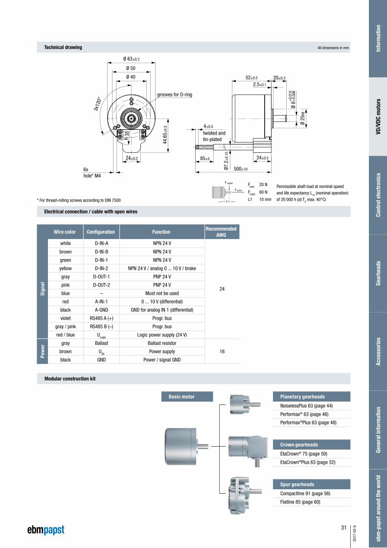
52±0.5 20±0.3
2.5±0.1
500±10
24±0.585±5
Ø7.2
±0.
15
twisted and tin-plated
Ø 25
h8
Ø 8+
0.00
6+
0.01
0
4±0.5
24±0.2
Ø 40
Ø 50
Ø 63±0.2
3x12
0°
44.6
5±0.
5
R 35
grooves for O-ring
6x hole* M4
Permissible shaft load at nominal speedand life expectancy L10 (nominal operation) of 20 000 h (at TU max. 40°C)
Wire color Configuration FunctionRecommended
AWG
Sign
al
Blue GND Logic power/signal GND
24
Pink S1 0 to 10 V – speed set Point
Green TXD Communication / programming interface
White RXD Communication / programming interface
Grey-Pink A Control input A, TTL level
Violet B Control input B, TTL level
Grey IST Actual value 1
Red-Blue F+ Frequency specification for speed setpoint
Brown S2 0 to +5 V current limitation (torque)
Black C Control input C – hardware enable
Red E Actual value 2
Yellow D Drive status
Pow
er
Blue GND Power supply GND
16Brown +UB Logic power supply
Black UZK Power supply

30
2017
-05-
b
– 3-phase external rotor motor with EC technology
– High-poled motor structure for optimum power density.
– Drive with completely integrated K4 operation and control electronics
– Integrated speed, torque and position control
– Selection of operating modes and parameter setting via RS485
– Interface with analog and digital control inputs
– Integrated brake chopper
– Robust mechanical design in IP 54 for industrial applications
– Electrical connection via cable with free wire ends
VDC motor.VDC-49.15-K4
Characteristic curve
1) Nominal data, see table1) Nominal data, see table
VDC-49.15-K4-B00 (at 25°C) VDC-49.15-K4-D00 (at 25°C)
Nominal data
Type VDC-49.15-K4-B00 VDC-49.15-K4-D00
Nominal voltage (UN) V DC 24 48
Nominal speed (nN)* min–1 4 000
Nominal torque (MN)* mNm 235 300
Nominal current (IN)* A 5.20 3.20
Nominal output power (PN)* W 99 126
Starting torque (Mmax) mNm 705 900
Permissible peak current (Imax)** A 15.6 9.60
Speed at no-load operation (nL) min–1 5 000
No-load current (IL) A 0.40 0.25
Recommended speed control range min–1 0 ... 4 000
Rotor moment of inertia (JR) kgm2 x10–6 108
Overload protection integrated
Permissible ambient temperature range (TU) °C 0 ... +40
Weight kg 0.59
Order no. (cable type)*** IP 54 937 4915 400 937 4915 402
Subject to alterations * At TU max. 40°C** Permissible time for peak current: max. 1 sec. – to be repeated only after complete cool down*** Classification of protection class refers to installed state with sealing on the flange sidePreferred type: ready to ship in 48 hours
6 000
5 000
4 000
3 000
2 000
1 000
0
20,0
16,7
13,3
10,0
6,7
3,3
0
MN
0 100 200 300 400 500 600 700 800
MMax
100
90
80
70
60
50
40
30
20
10
0
Effic
ienc
y
[%
]
Torque M [mNm]
Curr
ent I
[A]
Continuous operation
Spee
d n
[min
-1]
6 000
5 000
4 000
3 000
2 000
1 000
0
20,0
16,7
13,3
10,0
6,7
3,3
0
MN
0 100 200 300 400 500 600 700 800 900 1 000 1100 1 200
MMax
100
90
80
70
60
50
40
30
20
10
0
Effic
ienc
y
[%
]
Torque M [mNm]
Curr
ent I
[A]
Continuous operation
Spee
d n
[min
-1]
31
2017
-05-
b
Modular construction kit
Faxial 20 N
Fradial 60 N
L1 10 mm
Planetary gearheads
NoiselessPlus 63 (page 44)
Performax® 63 (page 46)
Performax®Plus 63 (page 48)
Crown gearheads
EtaCrown® 75 (page 50)
EtaCrown®Plus 63 (page 52)
Spur gearheads
Compactline 91 (page 56)
Flatline 85 (page 60)
Technical drawing
Electrical connection / cable with open wires
All dimensions in mm
Faxial
Fradial
L1* For thread-rolling screws according to DIN 7500
Wire color Configuration FunctionRecommended
AWG
Sign
al
white D-IN-A NPN 24 V
24
brown D-IN-B NPN 24 V
green D-IN-1 NPN 24 V
yellow D-IN-2 NPN 24 V / analog 0 ... 10 V / brake
gray D-OUT-1 PNP 24 V
pink D-OUT-2 PNP 24 V
blue – Must not be used
red A-IN-1 0 ... 10 V (differential)
black A-GND GND for analog IN 1 (differential)
violet RS485 A (+) Progr. bus
gray / pink RS485 B (–) Progr. bus
red / blue ULogic Logic power supply (24 V)
Pow
er
gray Ballast Ballast resistor
16brown UZK Power supply
black GND Power / signal GND
Basic motor
Info
rmat
ion
VD/V
DC m
otor
sCo
ntro
l ele
ctro
nics
Gear
head
sAc
cess
orie
sGe
nera
l inf
orm
atio
neb
m-p
apst
aro
und
the
wor
ld
52±0.5 20±0.3
2.5±0.1
500±10
24±0.585±5
Ø7.2
±0.
15
twisted and tin-plated
Ø 25
h8
Ø 8+
0.00
6+
0.01
0
4±0.5
24±0.2
Ø 40
Ø 50
Ø 63±0.2
3x12
0°
44.6
5±0.
5
R 35
grooves for O-ring
6x hole* M4
Permissible shaft load at nominal speedand life expectancy L10 (nominal operation) of 20 000 h (at TU max. 40°C)

32
2017
-05-
b

33
2017
-05-
b
Control electronics.
VTD-XX.XX-K3 (speed) 34
VTD-XX.XX-K4S (position) 36
VTD-60.13-K5SB (CANopen) 38
Info
rmat
ion
VD/V
DC m
otor
sCo
ntro
l ele
ctro
nics
Gear
head
sAc
cess
orie
sGe
nera
l inf
orm
atio
neb
m-p
apst
aro
und
the
wor
ld
34
2017
-05-
b
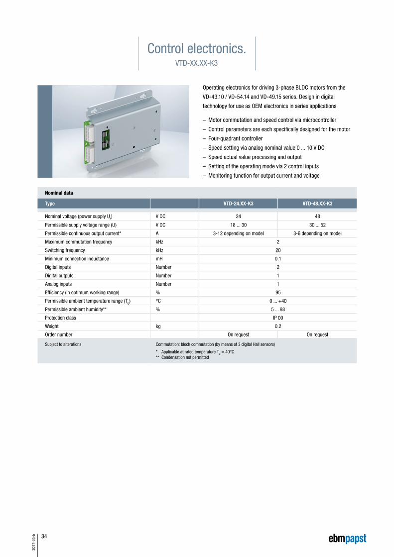
Operating electronics for driving 3-phase BLDC motors from the
VD-43.10 / VD-54.14 and VD-49.15 series. Design in digital
technology for use as OEM electronics in series applications
– Motor commutation and speed control via microcontroller
– Control parameters are each specifically designed for the motor
– Four-quadrant controller
– Speed setting via analog nominal value 0 ... 10 V DC
– Speed actual value processing and output
– Setting of the operating mode via 2 control inputs
– Monitoring function for output current and voltage
Nominal data
Type VTD-24.XX-K3 VTD-48.XX-K3
Nominal voltage (power supply UN) V DC 24 48
Permissible supply voltage range (U) V DC 18 ... 30 30 ... 52
Permissible continuous output current* A 3-12 depending on model 3-6 depending on model
Maximum commutation frequency kHz 2
Switching frequency kHz 20
Minimum connection inductance mH 0.1
Digital inputs Number 2
Digital outputs Number 1
Analog inputs Number 1
Efficiency (in optimum working range) % 95
Permissible ambient temperature range (TU) °C 0 ... +40
Permissible ambient humidity** % 5 ... 93
Protection class IP 00
Weight kg 0.2
Order number On request On request
Subject to alterations Commutation: block commutation (by means of 3 digital Hall sensors)
* Applicable at rated temperature TU = 40°C ** Condensation not permitted
Control electronics.VTD-XX.XX-K3

35
2017
-05-
b
Technical drawing
Accessories
Electrical connection
Pin Control plug X3 Motor plug X4 Capacitor plug X5
1 A Operating mode L3 Motor phase U+ Capacitor connector
2 +UB Operating voltage +U-Hall Hall sensor supply U- Capacitor connector
3 n.c. Not allocated RLG2 Hall signal 2 BR Braking resistor
4 S+ Set value input RLG1 Hall signal 1
5 B Operating mode L2 Motor phase 2
6 Actual Actual speed value L1 Motor phase 1
7 GND Ground GND Hall Ground Hall sensor supply
8 S- Ground set value input RLG3 Hall signal 3
All dimensions in mm
Connection cables X3
Type Order no.
X3 Control plug 194 0017 000
Color assignment
No. Color Function
1 white (AWG 20) A
2 red (AWG 18) +UB
3 violet (AWG 20) n.c.
4 green (AWG 20) S+
5 gray (AWG 20) B
6 yellow (AWG 20) Actual
7 black (AWG 18) GND
8 brown (AWG 20) S-
500±10
3±0.5
4 873
2
1
6
5
Stripped, twisted and tin-plated
View without wires
Info
rmat
ion
VD/V
DC m
otor
sCo
ntro
l ele
ctro
nics
Gear
head
sAc
cess
orie
sGe
nera
l inf
orm
atio
neb
m-p
apst
aro
und
the
wor
ld
36
2017
-05-
b
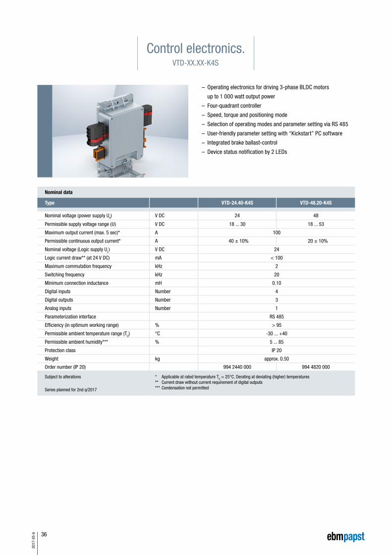
Control electronics.VTD-XX.XX-K4S
– Operating electronics for driving 3-phase BLDC motors
up to 1 000 watt output power
– Four-quadrant controller
– Speed, torque and positioning mode
– Selection of operating modes and parameter setting via RS 485
– User-friendly parameter setting with “Kickstart” PC software
– Integrated brake ballast-control
– Device status notification by 2 LEDs
Nominal data
Type VTD-24.40-K4S VTD-48.20-K4S
Nominal voltage (power supply UN) V DC 24 48
Permissible supply voltage range (U) V DC 18 ... 30 18 ... 53
Maximum output current (max. 5 sec)* A 100
Permissible continuous output current* A 40 ± 10% 20 ± 10%
Nominal voltage (Logic supply UL) V DC 24
Logic current draw** (at 24 V DC) mA < 100
Maximum commutation frequency kHz 2
Switching frequency kHz 20
Minimum connection inductance mH 0.10
Digital inputs Number 4
Digital outputs Number 3
Analog inputs Number 1
Parameterization interface RS 485
Efficiency (in optimum working range) % > 95
Permissible ambient temperature range (TU) °C -30 ... +40
Permissible ambient humidity*** % 5 ... 85
Protection class IP 20
Weight kg approx. 0.50
Order number (IP 20) 994 2440 000 994 4820 000
Subject to alterations
Series planned for 2nd q/2017
* Applicable at rated temperature TU = 25°C, Derating at deviating (higher) temperatures ** Current draw without current requirement of digital outputs*** Condensation not permitted

37
2017
-05-
b
96 41
157
X 106
X 100
X 102
X 107
X 101
Status LEDs
Electrical connection
PinX100SignalsLogic supply
X101Hall sensors
X102Parameterization interface
X106Power supply, controller
X107Power supply, motor
1 D-OUT-1 +U Hall (5V) FE Ballast U
2 D-OUT-2 GND RS485 B (-) P-GND V
3 D-OUT-3 Hall A RS485 A (+) UZK W
4 ULogic Hall B FE FE
5 GND Hall C
6 FE (Functional earth) +Usin/cos (5V)
7 D-IN-A GND
8 D-IN-B SIN
9 D-IN-1 COS
10 D-IN-2 FE
11 A-IN-1
12 A-IN-GND
Mating connectors are included in delivery
Technical drawing
Accessories
All dimensions in mm
Info
rmat
ion
VD/V
DC m
otor
sCo
ntro
l ele
ctro
nics
Gear
head
sAc
cess
orie
sGe
nera
l inf
orm
atio
neb
m-p
apst
aro
und
the
wor
ld
Image of “Kickstart” PC software
Commissioning tool
“Kickstart” (page 64)
“Kickstart” PC software for commissioning/ parametrization of the drive controller
Power supply
Motor VDC-49.XX-K1
PC with Kickstartsoftware
Controller
Control electronics
Commissioning setup
Interface adapterOrder no. 914 0000 400

38
2017
-05-
b
Nominal data
Type VTD-60.13-K5SB
Nominal voltage (Power supply UN) V DC 24 48
Permissible supply voltage range (U) V DC 9 ... 60
Maximum output current* A 50
Permissible continuous output current* A 12.5 (at 24 V) 12.5 (at 24 V)
Nominal voltage (Logic supply UL) V DC 9 ... 30
Logic current draw** (at 24 V DC) mA 60
Maximum commutation frequency kHz 2
Switching frequency kHz 32
Minimum connection inductance mH 0.20
Digital inputs Number 8
Digital outputs Number 2
Analog inputs Number 2
Parameterization interface CANopen
Efficiency (in optimum working range) % 95
Permissible ambient temperature range (TU) °C 0 ... +70
Permissible ambient humidity*** % 5 ... 85
Protection class IP 20
Weight kg 0.31
Order number (IP 20) 994 6013 000
Subject to alterations Commutation: block commutation (by means of 3 digital Hall sensors)
* Applicable at rated temperature TU = 25°C, Derating at deviating (higher) temperatures ** Current draw without current requirement of digital outputs *** Condensation not permitted
– Compact four-quadrant controller for BLDC motors
– CANopen interface (Protocol DS301, Device profile DS402)
– Integrated digital inputs
– Integrated digital outputs
– Integrated analog inputs
– Overvoltage, undervoltage and overtemperature monitoring
– Device status notification by 3 LEDs (Power, Status, Error)
– Hex switch for setting the device node ID
– Freely programmable due to built in MPU (Motion Process Unit)
Control electronics.VTD-60.13-K5SB

39
2017
-05-
b
Technical drawing
Accessories
Electrical connection
Pin X1 Motor X2 Hall sensors and encoder X3 I/O's and CAN X4 I/O's
1 FE Functional earth H1 Hall sensor signal 1 ULogic
Power supplyElectronics
A-IN-1 Analog input 1
2 +UpPower supply Power
H2 Hall sensor signal 2 A-IN-0 + Analog input 0, plus D-IN-4 Digital input 4
3 GNDGround for power supply voltage
H3 Hall sensor signal 3 D-IN-0 Digital input 0 D-IN-5 Digital input 5
4 Ma Motor phase A A Incremental encoder – A channel D-IN-1 Digital input 1 D-IN-6 Digital input 6
5 Mb Motor phase B B Incremental encoder – B channel D-IN-2 Digital input 2 D-OUT-1 Digital output 1
6 Mc Motor phase C Inx Incremental encoder – index channel D-IN-3 Digital input 3 D-IN-7 Digital input 7
7 +U5V
5V auxiliary voltage (Hall and encoder)
GNDGround for electronic supply voltage
8 /H1 Hall sensor signal 1 inverted A-IN-0 - Analog input 0, minus
9 /H2 Hall sensor signal 2 inverted D-OUT-0 Digital output 0
10 /H3 Hall sensor signal 3 inverted CAN Hi CAN High
11 /A Incremental encoder – A channel inverted CAN Lo CAN Low
12 /B Incremental encoder – B channel inverted CAN GND CAN Ground
13 /Inx Incremental encoder – index channel inverted
14 GND Ground for auxiliary voltage
All dimensions in mm
Mating connectors are included in delivery
PC with software“EP-Tools”
Motor VDC-49.15-K1 Arrangement Commissioning
Commissioning tool
“EP-Tools” (page 65)
Interface adapter
Control electronics
Info
rmat
ion
VD/V
DC m
otor
sCo
ntro
l ele
ctro
nics
Gear
head
sAc
cess
orie
sGe
nera
l inf
orm
atio
neb
m-p
apst
aro
und
the
wor
ld

40
2017
-05-
b

41
2017
-05-
b
Gearheads.
NoiselessPlus 63 (planetary gearhead) 44
Performax® 63 (planetary gearhead) 46
Performax®Plus 63 (planetary gearhead) 48
EtaCrown® 75 (crown gearhead) 50
EtaCrown®Plus 63 (crown gearhead) 52
Compactline 90 (spur gearhead) 54
Compactline 91 (spur gearhead) 56
Compactline 92 (spur gearhead) 58
Flatline 85 (spur gearhead) 60
Information on operating factor, lifetime, efficiency 70
Info
rmat
ion
VD/V
DC m
otor
sCo
ntro
l ele
ctro
nics
Gear
head
sAc
cess
orie
sGe
nera
l inf
orm
atio
neb
m-p
apst
aro
und
the
wor
ld
42
2017
-05-
b
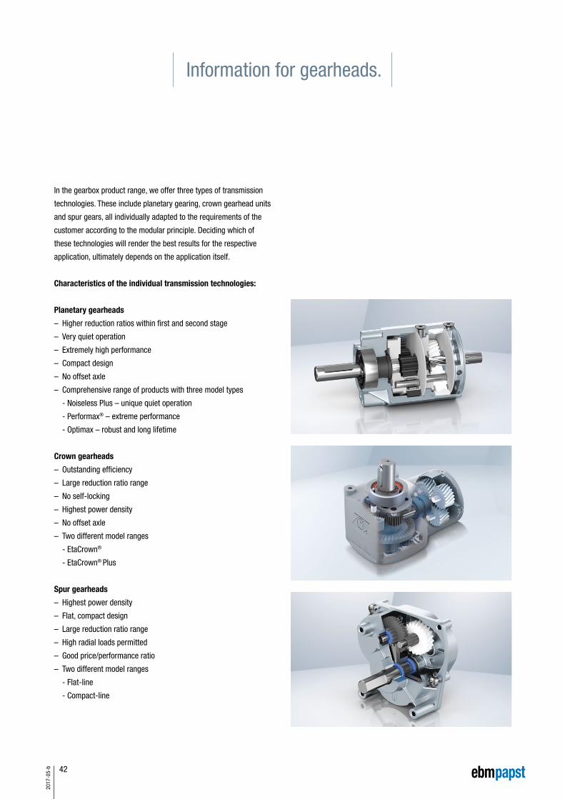
In the gearbox product range, we offer three types of transmission
technologies. These include planetary gearing, crown gearhead units
and spur gears, all individually adapted to the requirements of the
customer according to the modular principle. Deciding which of
these technologies will render the best results for the respective
application, ultimately depends on the application itself.
Characteristics of the individual transmission technologies:
Planetary gearheads
– Higher reduction ratios within first and second stage
– Very quiet operation
– Extremely high performance
– Compact design
– No offset axle
– Comprehensive range of products with three model types
- Noiseless Plus – unique quiet operation
- Performax® – extreme performance
- Optimax – robust and long lifetime
Crown gearheads
– Outstanding efficiency
– Large reduction ratio range
– No self-locking
– Highest power density
– No offset axle
– Two different model ranges
- EtaCrown®
- EtaCrown® Plus
Spur gearheads
– Highest power density
– Flat, compact design
– Large reduction ratio range
– High radial loads permitted
– Good price/performance ratio
– Two different model ranges
- Flat-line
- Compact-line
Information for gearheads.

43
2017
-05-
b
Info
rmat
ion
VD/V
DC m
otor
sCo
ntro
l ele
ctro
nics
Gear
head
sAc
cess
orie
sGe
nera
l inf
orm
atio
neb
m-p
apst
aro
und
the
wor
ld
The comprehensive range of planetary gearbox products is used
when the application does not allow axle misalignment.
When it comes to achieving high efficiency with minimal noise, the
NoiselessPlus is the impressive obvious choice. Exemplary smooth
running is achieved thanks to extremely sturdy, low-wear plastic
planetary wheels in an aluminium housing with bevelled teeth. Double
ball bearing output shafts efficiently absorb the forces acting on the
shaft at high radial loads. The output shafts of the NoiselessPlus
gearheads are made of hardened and ground case-hardened steel
and are thus particularly durable.
Performax® is an innovative, patent-pending concept of high-perfor-
mance planetary gearheads.
With its pioneering design, Performax® gearheads are popular for
their outstanding power density, ultimate smoothness and unique
reduction ranges. Transmissions of up to 17:1 in one stage allow
the use of single-stage gearheads, whereas competitors‘ products
already require a two-stage design. The design features of the series
include helical plastic gear wheels in the first stage and in the second
stage, straight toothing in the zinc diecast casting with case-hardened
planetary wheels. Another special standard feature of Performax®
gearheads is the planetary wheels of the second stage.
These have needle bearings, which really sets the series apart from
the regular planetary gearheads available on the market.
EtaCrown® is the name of the innovative angular gear with crown
gearhead technology.
Our vision of making crown gearheads smaller, more powerful and
more efficient, and above al to manufacture them more economically,
is now a reality. EtaCrown® significantly improves energy efficiency
and cost-effectiveness of drive solutions. The modular design can be
flexibly adapted for any drive task. Characteristic is its very compact
design and space-saving geometry with a symmetrical structure and
maximum performance density. Transmissions of 4:1 to 113:1 are
available as standard. Also standard is jolt-free start-up due to rolling
tooth gripping. Smooth running due to intelligent gear-tooth technolo-
gy and gearhead design, while maximum radial load thanks to
double-sided support of the drive shaft are also part of its features.
A special feature among angular drives is the self-locking capacity,
which does not exist in the technology. In contrast to other gearbox
technologies, this offers optimal protection against vandalism.
The range of gearboxes is rounded off by the spur gearhead sys-
tems of the Flatline and Compactline series.
In the first transmission stage, these have helically toothed plastic
wheels, thus achieving optimum noise reduction. The following gear
stages are optimally configured in terms of running noise and torque
to be transferred. Ground and hardened output shafts and hardened
gearwheels are standard in all Flatline series gearheads. Die-cast
zinc is used as a housing material. Gearheads of the Flatline design
are particularly suitable for use in applications with limited installa-
tion lengths. In drives of the Compactline series, where the wheel
widths were dimensioned in order to minimise noise particularly in
the first stage, due attention was paid to having the greatest possible
wheel width and therefore to a good contact ratio between the motor
shaft and the combing gearwheel.
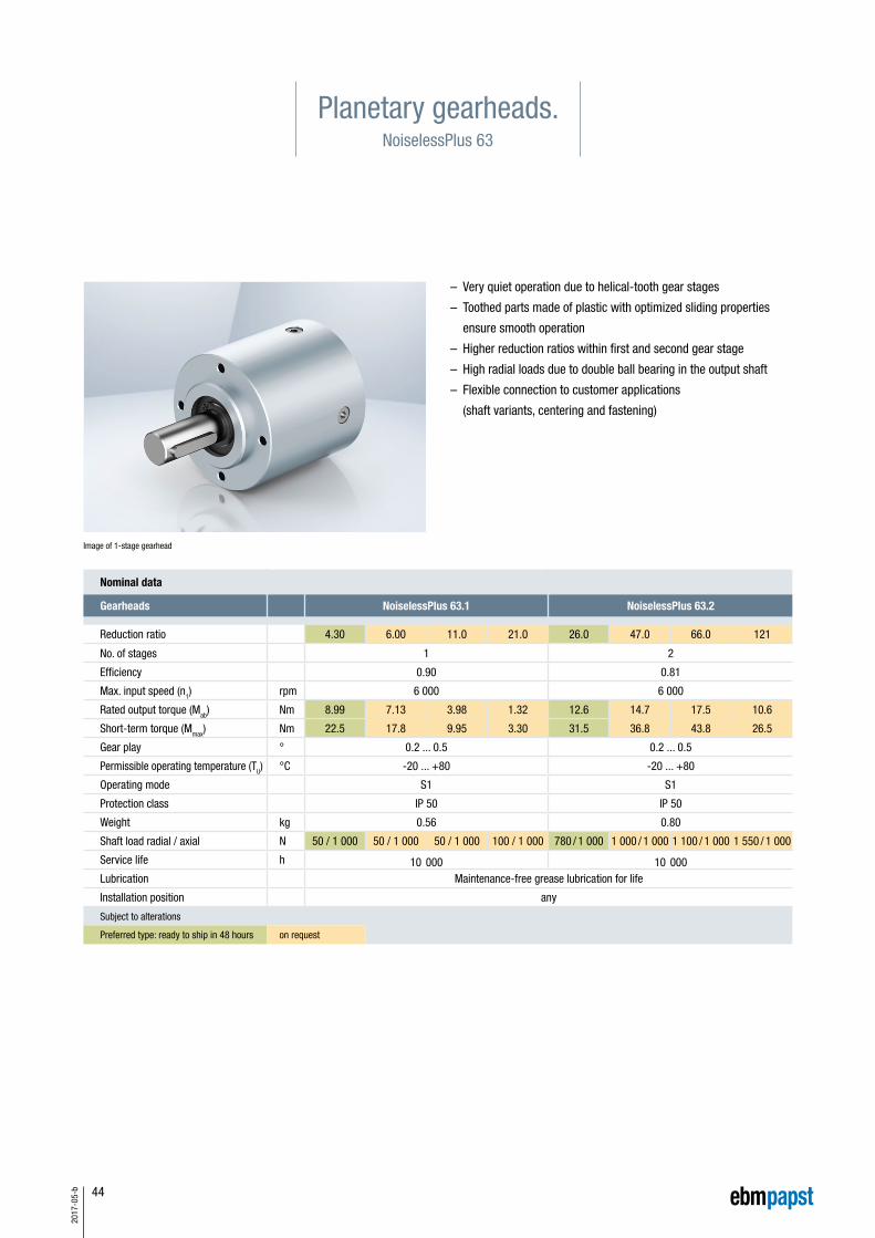
44
2017
-05-
b
Planetary gearheads.NoiselessPlus 63
Nominal data
Gearheads NoiselessPlus 63.1 NoiselessPlus 63.2
Reduction ratio 4.30 6.00 11.0 21.0 26.0 47.0 66.0 121
No. of stages 1 2
Efficiency 0.90 0.81
Max. input speed (n1) rpm 6 000 6 000
Rated output torque (Mab) Nm 8.99 7.13 3.98 1.32 12.6 14.7 17.5 10.6
Short-term torque (Mmax) Nm 22.5 17.8 9.95 3.30 31.5 36.8 43.8 26.5
Gear play ° 0.2 ... 0.5 0.2 ... 0.5
Permissible operating temperature (TU) °C -20 ... +80 -20 ... +80
Operating mode S1 S1
Protection class IP 50 IP 50
Weight kg 0.56 0.80
Shaft load radial / axial N 50 / 1 000 50 / 1 000 50 / 1 000 100 / 1 000 780 / 1 000 1 000 / 1 000 1 100 / 1 000 1 550 / 1 000
Service life h 10 000 10 000Lubrication Maintenance-free grease lubrication for life
Installation position any
Subject to alterations
Preferred type: ready to ship in 48 hours on request
Image of 1-stage gearhead
– Very quiet operation due to helical-tooth gear stages
– Toothed parts made of plastic with optimized sliding properties
ensure smooth operation
– Higher reduction ratios within first and second gear stage
– High radial loads due to double ball bearing in the output shaft
– Flexible connection to customer applications
(shaft variants, centering and fastening)

45
2017
-05-
b
Technical drawing
Faxial 1 000 N
Fradial see table
L1 19 mm
Permissible shaft load at nominal speed and life
expectancy L10 (nominal operation) and operating factor
CB = 1 (see page 70) of 10 000 h (at TU 40°C).
Image of 1-stage gearhead / All dimensions in mm
Faxial
Fradial
L1
Info
rmat
ion
VD/V
DC m
otor
sCo
ntro
l ele
ctro
nics
Gear
head
sAc
cess
orie
sGe
nera
l inf
orm
atio
neb
m-p
apst
aro
und
the
wor
ld
Length of the possible motor / gearhead combinations
Motor / gearhead L - 1-stage L - 2-stage
VD-49.15-K1-NP63 mm 120 152
VDC-49.15-K3-NP63 mm 120 152
VDC-49.15-K4-NP63 mm 120 152
Subject to alterations

46
2017
-05-
b
Planetary gearheads.Performax® 63
Image of 1-stage gearhead
Nominal data
Gearheads Performax® 63.1 Performax® 63.2
Reduction ratio 5.00 9.00 17.0 21.25 30.0 38.25 54.0 72.3 102 204
No. of stages 1 2
Efficiency 0.90 0.81
Max. input speed (n1) rpm 6 000 6 000
Rated output torque (Mab) Nm 6.91 2.20 1.50 12.0 37.3 8.30 11.8 5.90 8.30 16.5
Short-term torque (Mmax) Nm 17.3 5.50 3.75 30.0 42.5 20.8 29.5 14.8 20.8 41.3
Gear play ° 0.7 ... 1.2 0.7 ... 1.2
Permissible operating temperature (TU) °C -20 ... +80 -20 ... +80
Operating mode S1 S1
Protection class IP 50 IP 50
Weight kg 0.40 0.60
Shaft load radial / axial N 350 / 500 350 / 500
Service life h 5 000 5 000
Lubrication Maintenance-free grease lubrication for life
Installation position any
Subject to alterations
Preferred type: ready to ship in 48 hours on request
– High power density from compact dimensions
– Very quiet operation due to helical teeth in the first gear stage
– Planetary wheels made of plastic with optimized sliding properties
in the first stage ensure smooth operation
– Large effective diameter thanks to radial screw connection
– Economical setup due to use of many individual parts which are
readily available on the market

47
2017
-05-
b
Technical drawing
Faxial 500 N
Fradial 350 N
L1 19 mm
Permissible shaft load at nominal speed and life
expectancy L10 (nominal operation) and operating factor
CB = 1 (see page 70) of 5 000 h (at TU 40°C).
Faxial
Fradial
L1
Image of 1-stage gearhead / 2-stage design completely cylindrical / All dimensions in mm
Info
rmat
ion
VD/V
DC m
otor
sCo
ntro
l ele
ctro
nics
Gear
head
sAc
cess
orie
sGe
nera
l inf
orm
atio
neb
m-p
apst
aro
und
the
wor
ld
Length of the possible motor / gearhead combinations
Motor / gearhead L - 1-stage L - 2-stage
VDC-49.15-K3-P63 mm 107 128
VDC-49.15-K4-P63 mm 107 128
Subject to alterations

48
2017
-05-
b
Planetary gearheads.Performax®Plus 63
Nominal data
Gearheads Performax®Plus 63.1 Performax®Plus 63.2
Reduction ratio 3.20 5.00 9.00 17.0 21.3 30.0 38.3 54.0 72.3 102 204
No. of stages 1 2
Efficiency 0.90 0.81
Max. input speed (n1) rpm 6 000 6 000
Rated output torque (Mab) Nm 6.50 11.9 7.60 4.40 45.2 64.0 28.9 41.0 16.9 23.9 27.4
Short-term torque (Mmax) Nm 16.3 29.8 19.0 11.0 113 160 72.3 102.5 42.3 59.8 68.5
Gear play ° 0.7 ... 1.2 0.7 ... 1.2
Permissible operating temperature (TU) °C -20 ... +80 -20 ... +80
Operating mode S1 S1
Protection class IP 50 IP 50
Weight kg 0.66 1.20
Shaft load radial / axial N 350 / 500 350 / 500
Service life h 5 000 5 000
Lubrication Maintenance-free grease lubrication for life
Installation position any
Subject to alterations
Preferred type: ready to ship in 48 hours on request
Image of 2-stage gearhead
– High torques thanks to large gearing width in the first gear stage
– Good shock resistance due to housing made of
case-hardened steel with linear tooth profile in the output stage
– Very quiet operation due to helical teeth in the first gear stage
– Planetary wheels made of plastic with optimized sliding properties
in the first stage ensure smooth operation
– Large effective diameter thanks to radial screw connection
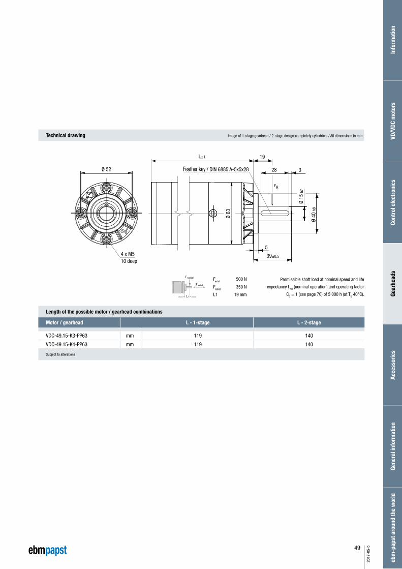
49
2017
-05-
b
Technical drawing
Faxial 500 N
Fradial 350 N
L1 19 mm
Permissible shaft load at nominal speed and life
expectancy L10 (nominal operation) and operating factor
CB = 1 (see page 70) of 5 000 h (at TU 40°C).
Faxial
Fradial
L1
Image of 1-stage gearhead / 2-stage design completely cylindrical / All dimensions in mm
Info
rmat
ion
VD/V
DC m
otor
sCo
ntro
l ele
ctro
nics
Gear
head
sAc
cess
orie
sGe
nera
l inf
orm
atio
neb
m-p
apst
aro
und
the
wor
ld
Length of the possible motor / gearhead combinations
Motor / gearhead L - 1-stage L - 2-stage
VDC-49.15-K3-PP63 mm 119 140
VDC-49.15-K4-PP63 mm 119 140
Subject to alterations

50
2017
-05-
b
Crown gearheads.EtaCrown® 75
Nominal data
Gearheads EtaCrown® 75.1 EtaCrown® 75.2
Reduction ratio 4.10 6.70 10.1 20.3 33.3 60.0 113
No. of stages 1 2
Efficiency 0.90 0.81
Max. input speed (n1) rpm 6 000 6 000
Rated output torque (Mab) Nm 6.00 5.00 2.43 10.0 10.0 10.0 10.0
Short-term torque (Mmax) Nm 15.0 12.5 6.08 25.0 25.0 25.0 25.0
Gear play ° 0.55 ... 1.10 0.55 ... 1.10
Permissible operating temperature (TU) °C -20 ... +80 -20 ... +80
Operating mode S1 S1
Protection class IP 50 IP 50
Weight kg 0.90 1.30
Shaft load radial / axial N 150 / 500 250 / 500 400 / 500 550 / 500 800 / 500 1 100 / 500 1 300 / 500
Service life h 5 000 5 000
Lubrication Maintenance-free grease lubrication for life
Installation position any
Subject to alterations
Preferred type: ready to ship in 48 hours on request
Image of 2-stage gearhead
– Maximum safety in design and operation, as well as optimal
vandalism protection; no automatic lock due to high efficiency of
the crown wheel technology
– Space-saving installation due to zero offset axle and symmetrical
structure
– Flexible application possibilities with various optional shaft outlets
and available shaft geometries
– Wide reduction range by means of upstream / downstream
planetary stage
– High radial loads due to double ball bearing in the output shaft

51
2017
-05-
b
Technical drawing
Faxial 500 N
Fradial see table
L1 15 mm
Permissible shaft load at nominal speed and life
expectancy L10 (nominal operation) and operating factor
CB = 1 (see page 70) of 5 000 h (at TU 40°C).
Image of 1-stage gearhead with right shaft end (W05) / All dimensions in mm
Faxial
Fradial
L1
Info
rmat
ion
VD/V
DC m
otor
sCo
ntro
l ele
ctro
nics
Gear
head
sAc
cess
orie
sGe
nera
l inf
orm
atio
neb
m-p
apst
aro
und
the
wor
ldLength of the possible motor / gearhead combinations
Motor / gearhead L - 1-stage L - 2-stage
VDC-49.15-K4-E75 mm 152 188
Subject to alterations
Shaft end, right (W05) (standard) Shaft end, left (W06) Shaft end, both sides (W07) Hollow shaft (W08)
Hollow shaft Ø 10 mm

52
2017
-05-
b
Crown gearheads.EtaCrown®Plus 63
Nominal data
Gearheads EtaCrown®Plus 63.3
Reduction ratio 54.0 84.8 153 289
No. of stages 3
Efficiency 0.73
Max. input speed (n1) rpm 6 000
Rated output torque (Mab) Nm 40.0 40.0 30.1 29.1
Short-term torque (Mmax) Nm 100 100 75.3 72.8
Gear play ° 0.7 ... 1.2
Permissible operating temperature (TU) °C -20 ... +80
Operating mode S1
Protection class IP 50
Weight kg 1.00
Shaft load radial / axial N 600 / 300
Service life h 5 000
Lubrication Maintenance-free grease lubrication for life
Installation position any
Subject to alterations
Preferred type: ready to ship in 48 hours on request
Image of 3-stage gearhead
– Compact design due to combination of the crown wheel and
planetary stage in one housing
– No automatic lock due to high efficiency of the crown wheel
technology
– High torques by using 5 straight toothed planetary gears made of
case-hardened sintered steel in the integrated planetary gear stage
– Wide reduction range thanks to possibility of an upstream
planetary stage
– Improved quiet operation thanks to the optimized design of
the crown wheel stage when using an upstream helical planetary
gear stage made of plastic with optimized sliding properties
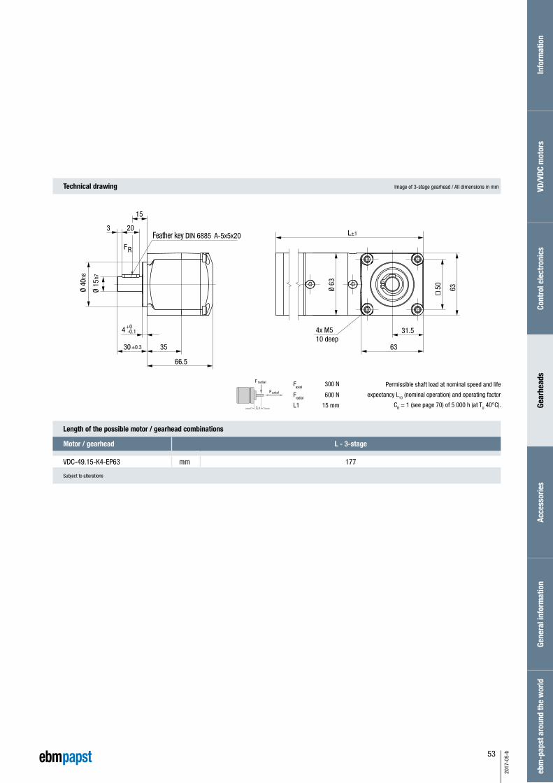
53
2017
-05-
b
Technical drawing
Faxial 300 N
Fradial 600 N
L1 15 mm
Permissible shaft load at nominal speed and life
expectancy L10 (nominal operation) and operating factor
CB = 1 (see page 70) of 5 000 h (at TU 40°C).
Image of 3-stage gearhead / All dimensions in mm
Faxial
Fradial
L1
Info
rmat
ion
VD/V
DC m
otor
sCo
ntro
l ele
ctro
nics
Gear
head
sAc
cess
orie
sGe
nera
l inf
orm
atio
neb
m-p
apst
aro
und
the
wor
ld
Length of the possible motor / gearhead combinations
Motor / gearhead L - 3-stage
VDC-49.15-K4-EP63 mm 177
Subject to alterations

54
2017
-05-
b
– Minimum space requirement due to compact design
– High power density
– High torques from the smallest possible dimensions
– Very quiet operation thanks to optimized gear geometries
and materials
– Maintenance-free over entire service life
Spur gearheads.Compactline 90
Nominal data
Gearheads Compactline 90.2 Compactline 90.3 Compactline 90.4
Reduction ratio 16.0 32.0 57.8 79.1 121.6 189.3 368
No. of stages 2 3 4
Efficiency 0.81 0.73 0.66
Max. input speed (n1) rpm 4 000 4 000 4 000
Rated output torque (Mab) Nm 1.90 3.80 6.20 7.00 7.00 9.00 9.00
Short-term torque (Mmax) Nm 4.75 9.50 15.50 17.5 17.5 22.5 22.5
Gear play ° 0.70 ... 1.60 0.70 ... 1.60 0.70 ... 1.60
Permissible operating temperature (TU) °C -20 ... +80 -20 ... +80 -20 ... +80
Operating mode S1 S1 S1
Protection class* IP 50 IP 50 IP 50
Weight kg 0.30 0.35 0.40
Shaft load radial / axial N 120 / 40 120 / 40 120 / 40
Service life h 5 000 5 000 5 000
Lubrication Maintenance-free grease lubrication for life
Installation position any
Subject to alterations * Classification of protection class refers to installed state with sealing on the flange side
on request

55
2017
-05-
b
Faxial 40 N
Fradial 120 N
L1 17 mm
Permissible shaft load at nominal speed and a
life expectancy L10 (nominal operation) and operating factor
CB = 1 (see page 70) of 5 000 h (at TU 40°C).
Mot
or
Faxial
Fradial
L1
Technical drawing All dimensions in mm
Info
rmat
ion
VD/V
DC m
otor
sCo
ntro
l ele
ctro
nics
Gear
head
sAc
cess
orie
sGe
nera
l inf
orm
atio
neb
m-p
apst
aro
und
the
wor
ld
Length of the possible motor / gearhead combinations
Motor / gearhead L
VD-43.10-K1-C90 mm 81
VDC-43.10-K3-C90 mm 82
VD-54.14-K1-C90 mm 84
VDC-54.14-K3-C90 mm 84
Subject to alterations

56
2017
-05-
b
Spur gearheads.Compactline 91
– Minimum space requirement due to compact design
– High power density
– High torques from the smallest possible dimensions
– Very quiet operation thanks to optimized gear geometries
and materials
– Maintenance-free over entire service life
Nominal data
Gearheads Compactline 91.2 Compactline 91.3
Reduction ratio (for motor 43.10 / 54.14) 11.3 26.4 38.6 117.1 165.8
No. of stages (for motor 49.15) 9.20 18.4 27.6
No. of stages 2 3
Efficiency 0.81 0.73
Max. input speed (n1) rpm 4 000 4 000
Rated output torque (Mab) Nm 7.00 9.00
Short-term torque (Mmax) Nm 17.5 22.5
Gear play ° 0.70 ... 1.20 0.70 ... 1.20
Permissible operating temperature (TU) °C -20 ... +80 -20 ... +80
Operating mode S1 S1
Protection class* IP 50 IP 50
Weight kg 0.30 0.30
Shaft load radial / axial N 150 / 50 150 / 50
Service life h 5 000 5 000
Lubrication Maintenance-free grease lubrication for life
Installation position any
Subject to alterations * Classification of protection class refers to installed state with sealing on the flange side
Preferred type: ready to ship in 48 hours on request
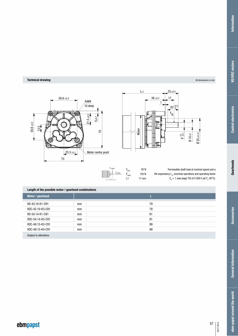
57
2017
-05-
b
Mot
or
Faxial 50 N
Fradial 150 N
L1 17 mm
Permissible shaft load at nominal speed and a
life expectancy L10 (nominal operation) and operating factor
CB = 1 (see page 70) of 5 000 h (at TU 40°C).
Faxial
Fradial
L1
Technical drawing All dimensions in mm
Info
rmat
ion
VD/V
DC m
otor
sCo
ntro
l ele
ctro
nics
Gear
head
sAc
cess
orie
sGe
nera
l inf
orm
atio
neb
m-p
apst
aro
und
the
wor
ld
Length of the possible motor / gearhead combinations
Motor / gearhead L
VD-43.10-K1-C91 mm 79
VDC-43.10-K3-C91 mm 79
VD-54.14-K1-C91 mm 81
VDC-54.14-K3-C91 mm 81
VDC-49.15-K3-C91 mm 99
VDC-49.15-K4-C91 mm 99
Subject to alterations
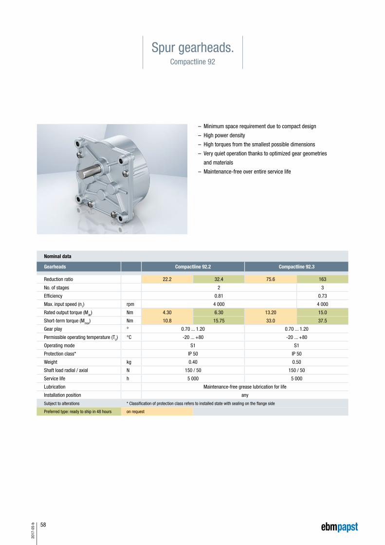
58
2017
-05-
b
Spur gearheads.Compactline 92
– Minimum space requirement due to compact design
– High power density
– High torques from the smallest possible dimensions
– Very quiet operation thanks to optimized gear geometries
and materials
– Maintenance-free over entire service life
Nominal data
Gearheads Compactline 92.2 Compactline 92.3
Reduction ratio 22.2 32.4 75.6 163
No. of stages 2 3
Efficiency 0.81 0.73
Max. input speed (n1) rpm 4 000 4 000
Rated output torque (Mab) Nm 4.30 6.30 13.20 15.0
Short-term torque (Mmax) Nm 10.8 15.75 33.0 37.5
Gear play ° 0.70 ... 1.20 0.70 ... 1.20
Permissible operating temperature (TU) °C -20 ... +80 -20 ... +80
Operating mode S1 S1
Protection class* IP 50 IP 50
Weight kg 0.40 0.50
Shaft load radial / axial N 150 / 50 150 / 50
Service life h 5 000 5 000
Lubrication Maintenance-free grease lubrication for life
Installation position any
Subject to alterations * Classification of protection class refers to installed state with sealing on the flange side
Preferred type: ready to ship in 48 hours on request

59
2017
-05-
b
Faxial 50 N
Fradial 150 N
L1 17 mm
Permissible shaft load at nominal speed and a
life expectancy L10 (nominal operation) and operating factor
CB = 1 (see page 70) of 5 000 h (at TU 40°C).
Faxial
Fradial
L1
Technical drawing All dimensions in mm
Info
rmat
ion
VD/V
DC m
otor
sCo
ntro
l ele
ctro
nics
Gear
head
sAc
cess
orie
sGe
nera
l inf
orm
atio
neb
m-p
apst
aro
und
the
wor
ld
Length of the possible motor / gearhead combinations
Motor / gearhead L
VD-54.14-K1-C92 mm 85
VDC-54.14-K3-C92 mm 85
Subject to alterations
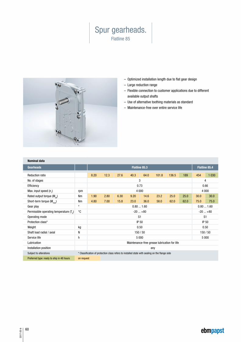
60
2017
-05-
b
Spur gearheads.Flatline 85
– Optimized installation length due to flat gear design
– Large reduction range
– Flexible connection to customer applications due to differ ent
available output shafts
– Use of alternative toothing materials as standard
– Maintenance-free over entire service life
Nominal data
Gearheads Flatline 85.3 Flatline 85.4
Reduction ratio 8.20 12.3 27.6 40.3 64.0 101.8 136.5 189 454 1 030
No. of stages 3 4
Efficiency 0.73 0.66
Max. input speed (n1) rpm 4 000 4 000
Rated output torque (Mab) Nm 1.90 2.80 6.30 9.20 14.6 23.2 25.0 25.0 30.0 30.0
Short-term torque (Mmax) Nm 4.80 7.00 15.8 23.0 36.0 58.0 62.0 62.0 75.0 75.0
Gear play ° 0.80 ... 1.60 0.80 ... 1.60
Permissible operating temperature (TU) °C -20 ... +80 -20 ... +80
Operating mode S1 S1
Protection class* IP 50 IP 50
Weight kg 0.50 0.50
Shaft load radial / axial N 150 / 50 150 / 50
Service life h 5 000 5 000
Lubrication Maintenance-free grease lubrication for life
Installation position any
Subject to alterations * Classification of protection class refers to installed state with sealing on the flange side
Preferred type: ready to ship in 48 hours on request

61
2017
-05-
b
L±1
Mot
or
Faxial 50 N
Fradial 150 N
L1 17 mm
Permissible shaft load at nominal speed and a
life expectancy L10 (nominal operation) and operating factor
CB = 1 (see page 70) of 5 000 h (at TU 40°C).
Faxial
Fradial
L1
Technical drawing All dimensions in mm
Info
rmat
ion
VD/V
DC m
otor
sCo
ntro
l ele
ctro
nics
Gear
head
sAc
cess
orie
sGe
nera
l inf
orm
atio
neb
m-p
apst
aro
und
the
wor
ld
Length of the possible motor / gearhead combinations
Motor / gearhead L
VDC-49.15-K3-F85 mm 88
VDC-49.15-K4-F85 mm 88
VDC-54.14-K3-F85 mm 70
Subject to alterations
Order add-on for motor mounting position
Gearhead VDC-49.15 VDC-54.14
C02 (Standard) C02-K02 C02-K03 C02-K04 K01 (Standard) K02 K03 K04
Bestellzusatz für Motor-Anschraub-position
VDC -3-49-15
VDC-3-54-14
C01(Standard) C01-K02
C02-K02
K02
C01-K03
C02-K03
K03
C01-K04
C02-K04
K04
C02(Standard)
K01(Standard)
Bestellzusatz für Motor-Anschraub-position
VDC -3-49-15
VDC-3-54-14
C01(Standard) C01-K02
C02-K02
K02
C01-K03
C02-K03
K03
C01-K04
C02-K04
K04
C02(Standard)
K01(Standard)
Bestellzusatz für Motor-Anschraub-position
VDC -3-49-15
VDC-3-54-14
C01(Standard) C01-K02
C02-K02
K02
C01-K03
C02-K03
K03
C01-K04
C02-K04
K04
C02(Standard)
K01(Standard)
Bestellzusatz für Motor-Anschraub-position
VDC -3-49-15
VDC-3-54-14
C01(Standard) C01-K02
C02-K02
K02
C01-K03
C02-K03
K03
C01-K04
C02-K04
K04
C02(Standard)
K01(Standard)
Bestellzusatz für Motor-Anschraub-position
VDC -3-49-15
VDC-3-54-14
C01(Standard) C01-K02
C02-K02
K02
C01-K03
C02-K03
K03
C01-K04
C02-K04
K04
C02(Standard)
K01(Standard)
Bestellzusatz für Motor-Anschraub-position
VDC -3-49-15
VDC-3-54-14
C01(Standard) C01-K02
C02-K02
K02
C01-K03
C02-K03
K03
C01-K04
C02-K04
K04
C02(Standard)
K01(Standard)
Bestellzusatz für Motor-Anschraub-position
VDC -3-49-15
VDC-3-54-14
C01(Standard) C01-K02
C02-K02
K02
C01-K03
C02-K03
K03
C01-K04
C02-K04
K04
C02(Standard)
K01(Standard)
Bestellzusatz für Motor-Anschraub-position
VDC -3-49-15
VDC-3-54-14
C01(Standard) C01-K02
C02-K02
K02
C01-K03
C02-K03
K03
C01-K04
C02-K04
K04
C02(Standard)
K01(Standard)

62
2017
-05-
b

63
2017
-05-
b
Accessories.
Commissioning tools 64
Accessories 66
Info
rmat
ion
VD/V
DC m
otor
sCo
ntro
l ele
ctro
nics
Gear
head
sAc
cess
orie
sGe
nera
l inf
orm
atio
neb
m-p
apst
aro
und
the
wor
ld

64
2017
-05-
b
The RS485 interface serves as an interface for parameterization and diagnosis. It can be operated using the freely available “Kickstart”
PC software. This requires a PC and the ebm-papst USB-CAN-RS485 adapter. Load your detailed operating manual and the PC software
“Kickstart” under www.ebmpapst.com.
Functional description of the LED displays
LED name Color Function assignment
Datared No assignment.
green Active data transfer via the USB-CAN-RS485 adapter.
Errorred
No response following request to K4.Receipt of a faulty data package.
green Received data is OK.
microSDred No assignment.
green Access to the memory card.
Commissioning tools.K4
Interface adapter for “Kickstart” PC software
Order number
USB-CAN-RS485 adapter 914 0000 400
Parameterization and commissioning Automatic operation
Automatic operation with stored parameters and integrated control
Power supply
Controller
Control electronics
Motor VDC-49.XX-K1
Commissioning setup
Interface adapterOrder no. 914 0000 400
PC with software“Kickstart”
Controller
Power supply
VDC-49.XX-K4 drive

65
2017
-05-
b
Functional description of the LED displays
LED name Color Display Function assignment
LED0 “Power” green
lights up Normal operation
does not light up No power supply
flashes Bootloader mode (no firmware)
LED1 “State” yellowdoes not light up Normal operation
flashes Bootloader mode (flashes with incoming message)
LED2 “Error” redlights up Error
does not light up No error (normal operation)
LED3 “Rx” greenflashes Flashes with incoming message
does not light up No incoming message
LED4 “Tx” yellowflashes Flashes with outgoing message
does not light up No outgoing message
Commissioning tools.K5
Parameterization and commissioning
Info
rmat
ion
VD/V
DC m
otor
sCo
ntro
l ele
ctro
nics
Gear
head
sAc
cess
orie
sGe
nera
l inf
orm
atio
neb
m-p
apst
aro
und
the
wor
ld
PC with software“EP-Tools”
Motor VDC-49.15-K1
Interface adapter
Commissioning setup
Control electronics
Commissioning tool for “EP-Tools” PC software
Order number
USB to CANStick 914 0000 401

66
2017
-05-
b
L1 L2
L3
Rotor protection cap All dimensions in mm
Protection cap
For type L1 L2 L3 Order no.
VD-35.0X 57 27.4 49.5 194 3506 000
VD-43.10 65 38.8 57.4 194 4310 000
VD-54.14 82 42.0 74.4 194 5414 000
Accessories.

67
2017
-05-
b
500±20
1
8
1
81234
5678
1
8
500±20
500±20
3±5 1
10
500±20
3±5
1
8
Info
rmat
ion
VD/V
DC m
otor
sCo
ntro
l ele
ctro
nics
Gear
head
sAc
cess
orie
sGe
nera
l inf
orm
atio
neb
m-p
apst
aro
und
the
wor
ld
Technical drawing connection cables K1
Technical drawing connection cables K3
All dimensions in mm
All dimensions in mm
Connection cables
For type Order no.
VD-35.06-K1194 0010 000
VD-43.10-K1
Connection cables
For type Order no.
VD-54.14-K1 194 0012 000
Connection cables
For type Order no.
VDC-43.10-K3 194 0009 000
Connection cables
For type Order no.
VDC-54.14-K3 194 0014 000
8 single wires / AWG 22
8 single wires / AWG 22
8 single wires / AWG 20
8 single wires / AWG 20

68
2017
-05-
b
Standards and guidelines.
Basic information on standards and guidelines for electrical
small-power motors and drive systems operated with a DC voltage
of max. 75 V DC (nominal voltage):
The VD/VDC series described in this catalog are direct current motors
in an electronically commutated design, which are designed and spec-
ified for a nominal voltage of max. 75 V DC. Thus the supply voltage of
these drives is within the range of safety extra-low voltage (SELV). On
this basis, ebm-papst would like to provide some information intended
to help you understand the classification of the motors from the rele-
vant EC Directives and the resulting consequences.
The CE label
In order to ensure a uniform safety level in the European internal
market, the European commission has implemented a new approach
for technical harmonization. This has been welcomed by all relevant
parties and is visible in many products as a CE label giving proof of
agreement with the harmonized provisions.
What does CE actually mean? Why don’t all products bear
the CE label?
CE is the abbreviation for “Communauté Européenne”. The harmonized
statutory provisions are a framework directive and belong to the
so-called New Approach. This framework directive defines the basic
requirements, putting in circulation and operation as well as the appli-
cable conformity assessment process. The manufacturer of a product
must now decide which framework directive applies to which product.
For electrical small-powered motors the following framework directive
can be applied:
1) Machinery Directive 2006/42/EC
2) Low Voltage Directive 2014/35/EU
3) EMC Directive 2014/30/EU
Based on these directives, ebm-papst St. Georgen GmbH & Co. KG
does not mark the electric motors and drive systems described with
the “CE” mark and does not issue an EC Declaration of Conformity.
The reason for this is consideration of the relevant EC Directives and
the definitions of the terms used, “Electric motor” and “Drive system”,
by ebm-papst St. Georgen GmbH & Co. KG.
Definition of the electric motor
An electric motor is a motor without electronics or a motor with inte-
grated electronics of low complexity, such as commutation sensors,
simple commutation electronics or commutation electronics with simple
speed control with a voltage range of <75 V DC (nominal voltage) for
use by customers who incorporate them into end devices.
According to this definition, electric motors include, for example,
the VD/VDC-XX.XX-K1 series.
Definition of drive systems
Drive systems are motors with built-in electronic control systems that
have a certain degree of complexity. These include electronic control
systems which, in addition to a speed control, offer other functions
such as current control or position control. This also includes electronic
control systems which, for example, have a CANopen interface or that
can be operated via programmable sequential controls. For these drive
systems, the voltage range of <75 V DC (nominal voltage) and the
intended use by customers who will use the systems in end devices
also apply. Drive systems include the VDC-XX.XX-K3 and
VDC-XX.XX-K4 series, for example.
Reasons according to the Machinery Directive 2006/42/EC
Electric motors are expressly exempt in Art. 1, Par. (2), lit. k) and thus
are NOT given the CE mark.
According to the definition of the term in Art. 2, lit. g), a drive system
is an “incomplete machine” and thus does not receive a CE mark, but
falls under the process for incomplete machines according to Art. 13.
Installation instructions to Annex IV and a Declaration of Incorporation
to Annex II, Part 1, Section B are available for each drive system.
The specific technical documents to Art. 13, Par. (1), lit. a) have been
created in-house and are archived for the government agencies of the
individual countries.
Based on this directive, the machine manufacturer is responsible for
verifying and ensuring compliance with the basic requirements of the
Machinery Directive.
Reasons according to the Low Voltage Directive 2014/35/EU
Due to the voltage ranges (nominal voltage), the specified electric
motors and drive systems do not fall under the application area of the
low voltage directive according to Art. 1.

69
2017
-05-
b
Reasons according to the EMC Directive 2014/30/EU
Because they are sold exclusively to customers who incorporate them
into end devices and not to the end user, the specified electric motors
and drive systems do not fall under the application area of the EMC
directive according to the definition of the term in Art. 3, Par. (2), 1: As
the small motors are supplied to companies who incorporate them into
end devices and not to the end user, ebm-papst has no control over
further use of the pre-fabricated components in devices, machines or
installations. Therefore, ebm-papst provides express notice that the
system manufacturer must provide a suitable EMC circuit when select-
ing the power supply and must provide for EMC-compliant installation
and use in the devices. For more information about EMC-compliant
installation and EMC safety measures, refer to resources such as the
IEC 61000-5-x series (Installation and Mitigation Guidelines).
Proper use
All drives in this catalog are determined for installation in permanently
connected, stationary end devices and machines in the industrial area
and must be operated on electricity only when in installed condition!
Operation is prohibited until it has been ascertained that this product,
along with the machine into which this product is to be installed,
complies with the protective requirements of the Machinery Directive.
If, when using our drives, market or application-specific product
standards apply, compliance with these must be verified and ensured
by the device manufacturer. This product is not intended for the end
consumer.
European Directive EC No. 2011/65/EU (RoHS)
Legally regulated substances
As an innovative company and trendsetter in the world of air techno-
logy and drive engineering, ebm-papst feels a special obligation
towards the environment. Accordingly, under the GreenTech logo, we
have implemented a comprehensive concept that extends from the
origin to the use of our products. This includes, of course, protecting
our environment and using natural resources in a way that conserves
them. This applies equally to our manufacturing processes and to our
products.
When developing our products, we already take into consideration any
possible negative consequences they may have for the environment.
Our goal is to prevent such environmental impact-even beyond the
extent mandated by law-or to reduce it to a minimum, and thus to
ensure sustainable development of our products. Thus we ensure that
our products are free of materials and substances that are prohibited
by law.
Of course, all current products have been designed for conformity with
European Directive 2011/65/EU (RoHS). All older products that do not
yet conform to these directives or parts thereof will be consistently
redesigned. Our suppliers are required to provide us only with goods
that conform to the directives. Thus we can confirm that basically, all
of our products listed in this catalog conform to the above-mentioned
directive. We are also available to help with any other questions you
may have on both these topics.
REACH Directive (EC No. 1907/2006)
The EU legal regulation for Registration, Evaluation, Authorization and
Restriction of Chemical substances (REACH) entered into force on
1 June 2007. This is a chemicals law intended to provide maximum
protection to health and the environment. As defined by the REACH
directive, ebm-papst is a downstream user. The units you purchase
from us are products as defined by REACH and thus do not require
registration. However, in our own interest and to ensure a high degree
of product safety, we track the implementation of REACH and the
resulting requirements as part of our duty to provide information.
To comply with the requirements of REACH, we are in contact with all
suppliers from whom we obtain chemicals (substances), preparations
and components that we use as part of our production process.
Within this framework, ebm-papst fulfills the obligations set forth
in the REACH regulation. If you have any other questions about the
implementation of the REACH directive in our company, please do
not hesitate to contact us.
RoHSIn
form
atio
nVD
/VDC
mot
ors
Cont
rol e
lect
roni
csGe
arhe
ads
Acce
ssor
ies
Gene
ral i
nfor
mat
ion
ebm
-pap
st a
roun
d th
e w
orld

70
2017
-05-
b
Operating factor, lifetime, efficiency.
Operating factor cB
To achieve a uniform lifetime for the gearheads and motors, the
necessary torques M must be increased by the respective operating
factor cB under the various operating loads so as not to exceed the
maximum permissible gearhead torque M2 max (see table below).
Operating mode
It is necessary to define the operating mode under which a gear motor
can be operated with certain nominal values in order to avoid over-
loading the motor and / or the gearhead. The values stated in this cata-
log refer to S1 operation (continuous operation). This means that the
gear motor can be constantly operated with the stated values, but can
also have a higher load placed on it for a short time. Please contact us
if you require more information about this.
Lifetime
Lifetime is limited by the various components in the drive. If frequently
overloaded, the gearhead components are subjected to more wear
than under nominal load. Extreme ambient and operating conditions
cause a reduction in the lifetime guaranteed for operation under oper-
ating ratio cB = 1.
Efficiency η (eta)
The efficiency per gear stage is at least 90%. Depending on the tooth
configuration and on the manufacturing quality, far better levels of
efficiency can also be achieved. The following overall efficiencies were
obtained for multi-stage gearheads:
Operating modes
Load Operating period in h/days
3 h 8 h 24 h 3 h 8 h 24 h
even gradual sudden up to 10 switching ops./h over 10 switching ops./h
One rotation direction � 1.00 1.00 1.20 1.00 1.20 1.52
Rotation direction change � 1.00 1.30 1.59 1.20 1.59 1.92
One rotation direction � 1.11 1.30 1.59 1.30 1.52 1.82
Rotation direction change � 1.41 1.72 2.00 1.59 1.89 2.33
One rotation direction � 1.20 1.52 1.82 1.52 1.82 2.22
Rotation direction change � 1.59 2.00 2.33 2.00 2.33 2.86
Overall efficiency
for 1-stage gearhead η = 0.9
for 2-stage gearhead η = 0.9 2 = 0.81
for 3-stage gearhead η = 0.9 3 = 0.73
for 4-stage gearhead η = 0.9 4 = 0.66
for 5-stage gearhead η = 0.9 5 = 0.59
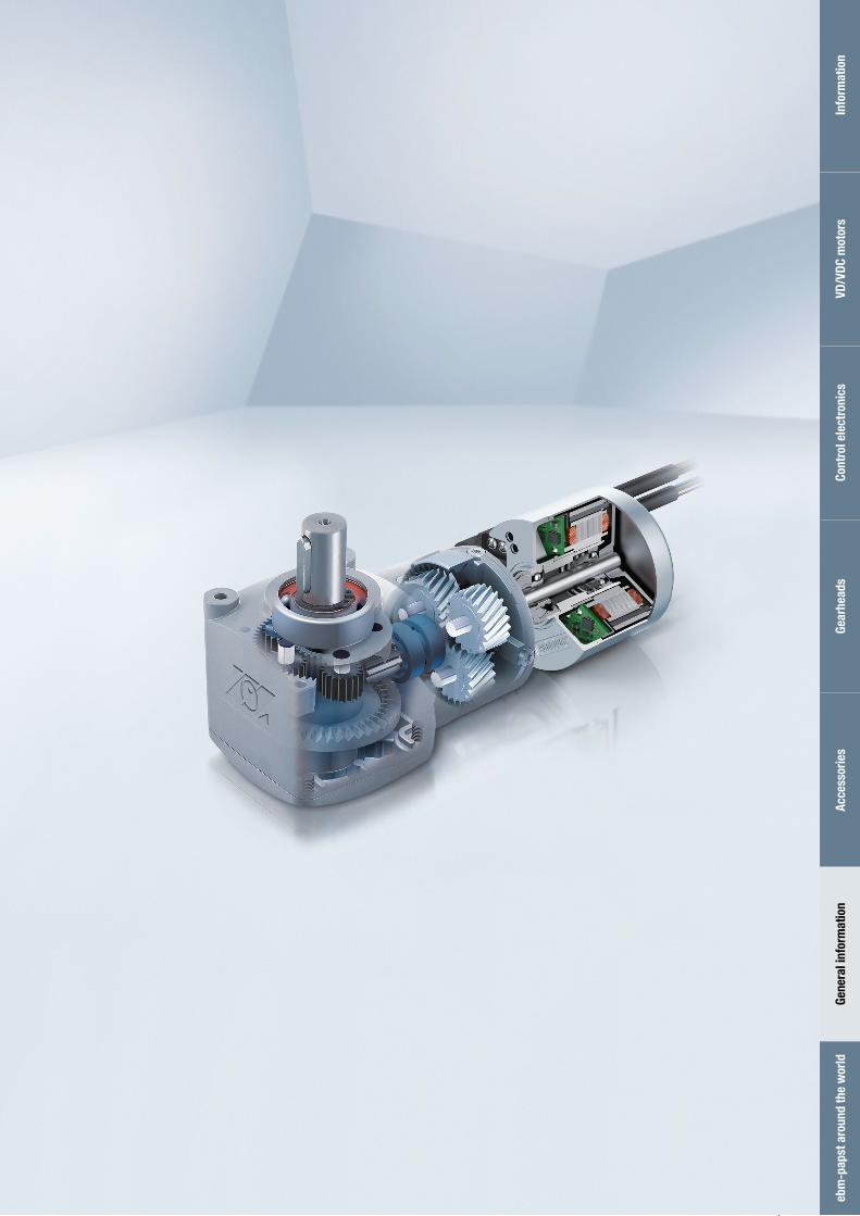
71
2017
-05-
b
Info
rmat
ion
VD/V
DC m
otor
sCo
ntro
l ele
ctro
nics
Gear
head
sAc
cess
orie
sGe
nera
l inf
orm
atio
neb
m-p
apst
aro
und
the
wor
ld

72
2017
-05-
b
Region in Germany.
Region north
Region Middle / East
Region Central / West
Region South / East 1
Region South / East 2
Region South / West

73
2017
-05-
b
ebm-papst around the world.
ebm-papst St. Georgen GmbH & Co. KGHermann-Papst-Straße 178112 St. GeorgenGermanyPhone +49 7724 81-0Fax +49 7724 [email protected]
ebm-papst ZEITLAUF GmbH & Co. KGIndustriestraße 991207 Lauf a. d. PegnitzGermanyPhone +49 9123 945-0Fax +49 9123 [email protected]
Germany
Northern regionNorderstedtBreuell & Hilgenfeldt GmbHUdo Wildenblanck Regional Sales Manager – Drive TechnologyOststraße 9622844 NorderstedtPhone +49 9123 945-291Fax +49 9123 [email protected]
Central / eastern regionSouthern / eastern region 1Dipl. oec. (VWA) Henry SämischWaldweg 315926 LuckauPhone +49 9123 945-292Fax +49 9123 [email protected]
Central / western regionMarkus PsikAm Dreispitz 1669502 HemsbachPhone +49 9123 945-293Fax +49 9123 [email protected]
Southern / western regionMeißenheimMichael WeberKarlstraße 1777974 MeißenheimPhone +49 9123 945-294Fax +49 9123 [email protected]
Southern / eastern region 2MunichDipl. Eng. (Univ.) Patrick ChristlevenFaustnerweg 1081479 MunichPhone +49 9123 945-295Fax +49 9123 [email protected]
Europe
Franceebm-papst sarlParc d’Activités Nord1 rue Mohler – BP 6267212 Obermai CedexPhone +33 3 88 66 88 [email protected]
Great Britainebm-papst Automotive & Drives (UK) Ltd.The SmithyFidlers LaneEast Ilsley, Berkshire RG20 7LGPhone +44 1635 2811-11Fax +44 1635 [email protected]
Italyebm-papst SrlVia Cornaggia 10822076 Mozzate (Co)Phone +39 0331 8362013Fax +39 0331 [email protected]
Beneluxebm-papst Benelux B.V.Polbeemd 7 – 5741 TP Beek en DonkP.O. Box 140 – 5740 AC Beek en DonkPhone +31 492 502-900Fax +31 492 [email protected]
Austria ebm-papst Motoren & Ventilatoren GmbHStraubingstraße 174030 LinzPhone +43 732 321150-0Fax +43 732 [email protected]
Russiaebm-papst Rus GmbHOlimpiyskiy prospect 29A, office 418141006 Mytistschi, Oblast MoscowPhone +7 495 9807524Fax +7 795 [email protected]
Swedenebm-papst ABÄggelundavägen 217562 JärfällaPhone +46 10 4544400Fax +46 8 [email protected]
Switzerlandebm-papst AGRütisbergstraße 1t8156 OberhasliPhone +47 44 73220-70Fax +41 44 [email protected]
America
USAebm-papst Automotive & Drives Inc.3200 Greenfield, Suite130Dearborn, MI 48120Phone +1 313 406-8080Fax +1 313 [email protected]
Asia
Chinaebm-papst Ventilator (Shanghai) Co., LtdNo. 418, Huajing RoadWaiGaoQiao Free Trade Zone200131 ShanghaiPhone +86 21 5046-0183Fax +86 21 [email protected] www.ebmpapst.com.cn
Indiaebm-papst India Pvt. Ltd.26/3, G.N.T. Road Erukkencherry600 118 ChennaiPhone +91 44 26720103Fax +91 44 [email protected] www.ebmpapst.in
Motor specialist Motor representative
Info
rmat
ion
VD/V
DC m
otor
sCo
ntro
l ele
ctro
nics
Gear
head
sAc
cess
orie
sGe
nera
l inf
orm
atio
neb
m-p
apst
aro
und
the
wor
ld

74
2017
-05-
b
Note.

www.ebmpapst.com 37967-7-8811 ∙ 2017-05 ∙ WA-2`
ebm-papst
St. Georgen GmbH & Co. KG
Hermann-Papst-Straße 1
78112 St. Georgen
Germany
Phone +49 7724 81-0
Fax +49 7724 81-1309
ebm-papst ZEITLAUF
GmbH & Co. KG
Industriestraße 9
91207 Lauf a. d. Pegnitz
Germany
Phone +49 9123 945-0
Fax +49 9123 945-145