Embed Size (px)
Citation preview

Compact PerformanceCP Modules
Electronics
Input modules type CP-E16...-M...-...Output modules type CP-A08...-M12-...

Author: S. BreuerEditors: H.-J. Drung, M. HolderLayout: Festo, KI-TD Typesetting: KI-TD
Edition: 9909c
© (Festo AG & Co., D-73726 Esslingen, Federal Republic of Germany, 1999)
The copying, distribution and utilization of this docu-ment as well as the communication of its contents toothers without expressed authorization is prohibited. Offenders will be held liable for the payment of dam-ages. All rights reserved, in particular the right to carryout patent, utility model or ornamental design registra-tions.P
rinte
d on
100
% r
ecyc
led
pape
r
CP..EA 9909c I

Part no. 165 225Title: ManualDesignation: P.BE-CPEA-GB
II CP..EA 9909c

Contents
Designated use. . . . . . . . . . . . . . . . . . . . . . . . . . . . . . . . . . . . . . . . . . . . . IVTarget group . . . . . . . . . . . . . . . . . . . . . . . . . . . . . . . . . . . . . . . . . . . . . . . . VImportant user instructions . . . . . . . . . . . . . . . . . . . . . . . . . . . . . . . . . . . . . VInformation on this manual . . . . . . . . . . . . . . . . . . . . . . . . . . . . . . . . . . . . VII
1. Input module type CP-E16...-M...-...
1.1 Mode of operation of input modules CP-E16...-M...-... . . . . . . . . 1-31.1.1 Display and connecting elements . . . . . . . . . . . . . . . . . . . . . . . . 1-41.2 Fitting . . . . . . . . . . . . . . . . . . . . . . . . . . . . . . . . . . . . . . . . . . . . . . 1-61.3 Installation. . . . . . . . . . . . . . . . . . . . . . . . . . . . . . . . . . . . . . . . . . 1-101.3.1 Configuring for PNP or NPN mode
(type CP-E16-M8-Z only) . . . . . . . . . . . . . . . . . . . . . . . . . . . . . . 1-111.3.2 Connecting the separate sensor supply
(type CP-E16-M8-Z only) . . . . . . . . . . . . . . . . . . . . . . . . . . . . . . 1-121.3.3 Connecting the sensors . . . . . . . . . . . . . . . . . . . . . . . . . . . . . . . 1-151.3.4 Connecting the input module . . . . . . . . . . . . . . . . . . . . . . . . . . . 1-261.4 Instructions on commissioning . . . . . . . . . . . . . . . . . . . . . . . . . . 1-281.5 Technical data . . . . . . . . . . . . . . . . . . . . . . . . . . . . . . . . . . . . . . 1-33
2. Output module type CP-A08...-M12-...
2.1 Overview. . . . . . . . . . . . . . . . . . . . . . . . . . . . . . . . . . . . . . . . . . . . 2-32.2 Fitting . . . . . . . . . . . . . . . . . . . . . . . . . . . . . . . . . . . . . . . . . . . . . . 2-42.3 Installation. . . . . . . . . . . . . . . . . . . . . . . . . . . . . . . . . . . . . . . . . . . 2-52.3.1 Connecting the actuators . . . . . . . . . . . . . . . . . . . . . . . . . . . . . . . 2-62.3.2 Connecting the output module . . . . . . . . . . . . . . . . . . . . . . . . . . 2-132.3.3 Connecting the load voltage. . . . . . . . . . . . . . . . . . . . . . . . . . . . 2-142.4 Instructions on commissioning . . . . . . . . . . . . . . . . . . . . . . . . . . 2-172.5 Technical specifications . . . . . . . . . . . . . . . . . . . . . . . . . . . . . . . 2-20
A. Index
CP..EA 9909c III

Designated use
The CP modules described in this manual have beendesigned exclusively for use on a CP string, an axisinterface string or a CP branch line in conjunction witha CP field bus node, the SPC200 Smart PositioningController or the Powerbox type CP-FB-TBOX-SUBD9.CP modules and CP cables may only be used asfollows:
– as intended for use
– in original condition
– without unauthorized modifications
– in faultless technical condition
If used in conjunction with commercially-available com-ponents such as sensors and actuators, the specifiedlimit values for pressures, temperatures, electrical data,torques etc. must be observed. Please comply also withnational and local safety laws and regulations.
All CP modules comply with protection class III.
WARNINGUse only power units which guarantee reliableisolation of the operating voltages as per IEC 742/EN 60742/VDE 0551 with at least 4 kV isolationresistance (protected extra low voltage, PELV).Switch power packs are permitted if they guaranteereliable isolation in accordance with EN 60950/VDE 0805.
IV CP..EA 9909c

Target group
This manual is directed exclusively at technicians whoare trained in control and automation technology.
Important user instructions
This manual contains instructions on the possibledangers which may occur if the CP modules are notused correctly. These instructions are always printed initalics, are framed and also signalled by pictograms.
Dangercategories
A distinction is made between the following:
WARNINGThis means that personal injury or damage toproperty may occur if these instructions are not observed.
CAUTIONThis means that damage to property may occur ifthese instructions are not observed.
PLEASE NOTEThis means that this instruction must also beobserved.
CP..EA 9909c V

Pictograms and symbols complement the danger warn-ings and draw attention to the nature and conse-quences of dangers.
Pictograms
The following pictograms are used:
Uncontrolled movements of loose tubing.
Unintentional movements of the connected actuators.
High voltages or undefined switching states of the elec-tronic components which may influence connected cir-cuits.
Electrostatically vulnerable components.These will be damaged if you touch the contact sur-faces.
• This mark indicates activities which can be carriedout in any order.
Textmarkings
1. Figures indicate activites which must be carried outin the numerical order of the figures.
– Hyphens indicate general, non-compulsory activities.
VI CP..EA 9909c

Information on this manual
CP I/O modules are available both as PNP (positive-switching) and NPN (negative-switching). The positive-switching modules with M12 connection are available in4-pin and 5-pin forms. The 5-pin design has an earthconnection. This manual contains specific informationon the method of operation, fitting, installation and com-missioning of the following CP modules:
This manual refers to:
Input modules:PNP- CP-E16-M8- CP-E16-M12x2- CP-E16-M12x2-5POLNPN- CP-E16N-M8- CP-E16N-M12x2PNP or NPN- CP-E16-M8-Z
Output modules:PNP- CP-A08-M12- CP-A08-M12-5POLNPN- CP-A08N-M12
Information on further modules as well as basic infor-mation which must be observed in conjunction with thehigher-order system, can be found in the manuals forthe relevant system.
CP..EA 9909c VII

Manuals for the CP system Peripherals
Manual "CP system, Installation and commissioning"type P.BE-CPSYS-...
Contents General, basic information on operating, fitting, installingand commissioning CP systems.
Manual "CP field bus node,programming anddiagnosing"type P.BE...-...
"CPV valveterminal,CPA valveterminal,pneumatics"type P.BE-CPV-..ortype P.BE-CPA-..
"CP modules,electronics"
Contents Special informationon commissioning,programming anddiagnosing related tothe node used.
Information onfitting, installingand commission-ing CP valveterminals
Information onfitting, installingandcommissioningCP I/O modules
Fig. 0/1: CP system manuals
VIII CP..EA 9909c

Manuals on the SPC200 Smart Positioning Controller Periphery
Manuals SPC200 SmartPositioningController, Usermanualtype P.BE-SPC200-...
ManualWinPISA typeP.SW-WIN-PISA-...
Manuals on:
- proportional directionalcontrol valves
- service unit- measuring system- cylinders or
linear drives
Contents Installation,commissioning anddiagnosis with theSPC200;Standardcomponents andmodules
Functions of theWinPISA softwarepackage
Manual "CPV valve terminal,pneumatics"type P.BE-CPV-...
"CP modules,electronics" type P.BE-CPEA-...
Contents Information on theCPV valve terminals
Information on theCP-I/O modules
Fig. 0/2: Manuals for the SPC200
CP..EA 9909c IX

X CP..EA 9909c

Chapter 1
Input module type CP-E16...-M...-...
1. Input module type CP-E16...-M...-...
CP-E16...-M... 9909c 1-1

Contents
Input module type CP-E16...-M...-...
1.1 Mode of operation of input modules CP-E16...-M...-... . . . . . . . 1-31.1.1 Display and connecting elements. . . . . . . . . . . . . . . . . . . . . . . . 1-41.2 Fitting . . . . . . . . . . . . . . . . . . . . . . . . . . . . . . . . . . . . . . . . . . . . . 1-61.3 Installation. . . . . . . . . . . . . . . . . . . . . . . . . . . . . . . . . . . . . . . . . 1-101.3.1 Configuring for PNP or NPN operation
(type CP-E16-M8-Z only) . . . . . . . . . . . . . . . . . . . . . . . . . . . . . 1-111.3.2 Connecting the separate sensor supply
(type CP-E16-M8-Z only) . . . . . . . . . . . . . . . . . . . . . . . . . . . . . 1-121.3.3 Connecting the sensors . . . . . . . . . . . . . . . . . . . . . . . . . . . . . . 1-151.3.4 Connecting the input module . . . . . . . . . . . . . . . . . . . . . . . . . . 1-261.4 Instructions on commissioning . . . . . . . . . . . . . . . . . . . . . . . . . 1-281.5 Technical data . . . . . . . . . . . . . . . . . . . . . . . . . . . . . . . . . . . . . 1-33
1. Input module type CP-E16...-M...-...
1-2 CP-E16...-M... 9909c

1.1 Mode of operation of input modules CP-E16...-M...-...
The CP input modules contain digital inputs for con-necting sensors, thereby enabling e.g. cylinder positionsto be interrogated. A distinction is made between thefollowing types:
Type Explanation
CP-E16-M12X2-...
CP-E16N-M12X2
Provides 16 PNP inputs; sensor connections via 8 sockets withM12 thread
Provides 16 NPN inputs;sensor connections via 8 sockets withM12 thread
CP-E16-M8
CP-E16N-M8
Provides 16 PNP inputs;sensor connections via 16 sockets withM8 thread
Provides 16 NPN inputs;sensor connections via 16 sockets withM8 thread
CP-E16-M8-Z Provides 16 PNP or 16 NPN inputsand a separate connection for thesensor supply voltage
1. Input module type CP-E16...-M...-...
CP-E16...-M... 9909c 1-3

1.1.1 Display and connecting elements
The diagram below shows the display and connectingelements using the example of input moduleCP-E16-M12x2.
1
23
Designation for input type:- INPUT-P for PNP inputs- INPUT-N for NPN inputsSensor connectionsGreen LED for status display(one LED per input)
456789
Status LED (green)CP connectionProtective capGroove for inscription signs (ISB 6x10)Earth connectionType plate
Fig. 1/1: Display and connecting elements
DIAG
POWER
INPUT-N
2
6
4
3
5
7
9
1
8
1. Input module type CP-E16...-M...-...
1-4 CP-E16...-M... 9909c

The following illustration shows the additional displayand connection points for the CP-E16-M8-Z input mo-dule.
1 Connection for sensor supply voltage 2 Red LED for indicating short circuit orloss of sensor voltage (one LED perinput group)
Fig. 1/2: Additional features of type CP-E16-M8-Z
1 2
2
1. Input module type CP-E16...-M...-...
CP-E16...-M... 9909c 1-5

1.2 Fitting
Input modules are intended for fitting onto walls or hatrails. For fitting them onto walls you will require the fol-lowing surface areas:
Type Surface area
CP-E16-M8 Approx. 150 mm x 66 mm
CP-E16-M8-Z Approx. 217 mm x 66 mm
CP-E16-M12x2-... Approx. 141 mm x 78 mm
The diagram below shows the dimensions of the fourthreaded holes of screw size M4.
Fitting ona wall
1. Input module type CP-E16...-M...-...
1-6 CP-E16...-M... 9909c

123
Input module, type CP-E16...-M12x2-...Input module, type CP-E16...-M8Input module, type CP-E16-M8-Z
Fig. 1/3: Fitting dimensions CP-E16...-M...-...
63 mm
131.9 mm
1
40 mm
139.9 mm
2
40 mm
207.9 mm
3
1. Input module type CP-E16...-M...-...
CP-E16...-M... 9909c 1-7

PLEASE NOTEFor fitting the modules onto a hat rail you will requirefastening kit CP-TS-HS35. This kit contains 2 fasten-ings, 2 M4x12 screws and 2 washers.
In order to fit the modules onto a hat rail, proceed asfollows:
Fitting onto ahat rail
1. Make sure that the fastening surface can supportthe weight of the module.
2. Fit a hat rail (support rail EN 50022 - 35x15; width35 mm, height 15 mm).
3. Fasten the hat rail at least every 100 mm to the sup-port surface.
4. Let both fastenings on the hat rail snap into themodule (see Fig. 1/4).
5. Screw the housing on to the fastening with thescrews supplied as shown in the diagram below.
6. Tighten the screws. The fastening and the housingwill then be clamped tight on the hat rail.
1. Input module type CP-E16...-M...-...
1-8 CP-E16...-M... 9909c

12345
FasteningHat railHousingM4x12 screwWasher
Fig. 1/4: Fitting on a hat rail
In order to remove the module from a hat rail, proceedas follows:
1. Loosen the screws.
2. Remove the housing.
3. Use a screwdriver to prize open the hat rail andremove the module.
12
FasteningScrewdriver
Fig. 1/5: Removing the module
1
2
1
2
3
5
4
1. Input module type CP-E16...-M...-...
CP-E16...-M... 9909c 1-9

1.3 Installation
WARNINGBefore undertaking installation work, switch off thefollowing:- the operating voltage supply and the load voltage
supply on the higher-order system (e.g. CP field bus node)
- if necessary, the separately supplied voltage supplies.
You thereby avoid:
– unintentional movements of the connected actuators.
– undefined switching states of the electronic compo-nents.
WARNINGConnect the earth cable on the side of the housing(see Fig. 1/1) with low impedance (short cable withlarge cross-sectional area) to the earth potential.In this way you can avoid interference caused byelectromagnetic influences.
1. Input module type CP-E16...-M...-...
1-10 CP-E16...-M... 9909c

1.3.1 Configuring for PNP or NPN operation(type CP-E16-M8-Z only)
The CP-E16-M8-Z input module provides PNP or NPNinputs. A bridge must be installed in the sensor supplysocket for setting to either PNP or NPN mode. The fol-lowing illustrations show the rear of the socket.
1 PNP mode (pins 2 and 3 bridged)
2 NPN mode (pins 2 and 1 bridged)
Pin assignment
Pin 1 + 24 V DC ± 25 %
Pin 2 PNP/NPN
Pin 3 0 V
Pin 4 NC
Pin 5 Earth connection
Fig. 1/6: Configuring for PNP or NPN (type CP-E16-M8-Z only)
3 2
4 1
51
3 2
4 1
52
1. Input module type CP-E16...-M...-...
CP-E16...-M... 9909c 1-11

1.3.2 Connecting the separate sensor supply(type CP-E16-M8-Z only)
WARNINGUse only power units which guarantee reliableisolation of the operating voltages as per IEC 742/EN 60742/VDE 0551 with at least 4 kV isolationresistance (protected extra low voltage, PELV).Switch power packs are permitted if they guaranteereliable isolation in accordance with EN 60950/VDE 0805.
By using PELV power units, protection against electricshock (protection against direct and indirect contact) inaccordance with EN 60204-1/IEC 204 is guaranteed onFesto valve terminals. Safety transformers with the ad-jacent designation must be used for supplying PELVnetworks. The CP input modules must be earthed inorder to ensure their function (e.g. EMC).
The sensors are supplied with DC + 24 V through thesensor supply connection. The module allows sensorshaving higher current draw to be used (max. 125 mAper sensor).
1. Input module type CP-E16...-M...-...
1-12 CP-E16...-M... 9909c

The following illustration shows the pin assignment aswell as a connection example for PNP mode (bridgebetween pins 2 and 3). See also "Configuring for PNPor NPN operation", section 1.3.1.
123
Earth connection pin 5Earth connection on housing sideSensor supply can be individually switched off; supplyvoltage is provided through the CP connection
Fig. 1/7: Pin assignment and wiring example for sensorsupply (PNP mode)
Pin 4:n.c.
Pin 2:PNP/NPN
Pin 1:24 V DC± 25 %
2
Pin 5:1
Pin 3:0 V
2 3 1 4 5
3
1. Input module type CP-E16...-M...-...
CP-E16...-M... 9909c 1-13

PLEASE NOTE• Always connect earth to pin 5 of the sensor supply.• Make sure the connection between the earth ter-
minal on the left housing side and GND is low-resistance (short lead, large gauge).
• Use low-resistance connections to ensure that themodule housing and the earth connection on pin 5are at the same potential and no compensation current flows.
In this way you will avoid electromagnetic disturbances.
1. Input module type CP-E16...-M...-...
1-14 CP-E16...-M... 9909c

1.3.3 Connecting the sensors
WARNINGWhen using the CP-E16-M8-Z input module, makesure that pin 2 on the sensor supply connection isbridged according to the operating mode of yoursystem (PNP or NPN, see section 1.3.1).
Use the following cable and plugs for connecting thesensors.
Type Plug Cable
CP-E16...-M12x2 SEA-GS-7 (PG7)SEA-WS-7 (PG7)
KM12-DUO-...
CP-E16-M12x2-5POL Use the plug withunion nut withthread M12x1.
CP-E16...-M8andCP-E16-M8-Z
Use the plug withunion nut withthread M8x1(outer diametermax. 12 mm).
KM8-M8-GSGD-...
Fasten the plugs with the aid of the union nuts in orderto avoid unintentional loosening e.g. due to vibration.Seal the unused sensor connections with the protectivecaps supplied. Only then is compliance with class ofprotection IP65 ensured.
1. Input module type CP-E16...-M...-...
CP-E16...-M... 9909c 1-15

Pin assignment (inputs PNP and NPN)
The following diagrams show the pin assignment of thesensor connections of the different CP input modules.
E = Input
Fig. 1/8: Pin assignment typ CP-E16...-M8 and CP-E16-M8-Z
E = Input
Fig. 1/9: Pin assignment type CP-E16...-M12x2
Ex+3ExEx+2
Pin 3: 0 V
Pin 4: Ex
Pin 1: 24 V
Pin 1: 24 V
Pin 4: Ex+2
Pin 3: 0 V
Pin 2: Ex+3
Ex+1
Pin 2: Ex+1
7
6
5
4
9
8
11
10
13
12
15
14
Pin 1: 24 VPin 3: 0 V
Pin 2: ExPin 3: 0 V
Pin 1: 24 V
Ex+1Ex
Pin 2: Ex+1
1. Input module type CP-E16...-M...-...
1-16 CP-E16...-M... 9909c

E = Input
1 Pin 5: Earth connection
Fig. 1/10: Pin assignment type CP-E16-M12x2-5POL
Ex+3ExEx+2
Pin 3: 0 V
Pin 4: Ex
Pin 1: 24 V
Pin 1: 24 V
Pin 4: Ex+2
Pin 3: 0 V
Pin 2: Ex+3
Ex+1
Pin 2: Ex+1
1
1
1. Input module type CP-E16...-M...-...
CP-E16...-M... 9909c 1-17

Internal layout of CP-E16-M8 (PNP inputs)and CP-E16-M8-Z (PNP mode)
123
PLC/I-PC Ex (e.g. via field bus)Logic recognition ExGreen LED Ex
Fig. 1/11: Internal layout
24 V + 10/- 15 %
2
Pin 1
Pin 2
Pin 3
31
0 V
1. Input module type CP-E16...-M...-...
1-18 CP-E16...-M... 9909c

Circuitry examples types CP-E16-M8 (PNP inputs)and CP-E16-M8-Z (PNP mode)
Pin assignment
Circuitry examples
123
Three-wire sensorTwo-wire sensorContact
E = Input
Fig. 1/12: Circuitry examples
Pin 1: 24 V
Pin 3: 0 V
Pin 2: Ex
2 31
1. Input module type CP-E16...-M...-...
CP-E16...-M... 9909c 1-19

Internal layout of CP-E16-M12x2-... (PNP inputs)
123
PLC/I-PC Ex+1 (e.g. via field bus)Logic recognition Ex+1Green LED Ex+1
4567
PLC/I-PC Ex (e.g. via field bus)Logic recognition ExGreen LED ExPin 5 only with typeCP-E16-M12x2-5POL: Earth connection
Fig. 1/13: Internal layout
24 V + 10/- 15 %Pin 1
Pin 2
5
3
2
Pin 4
Pin 3
4
1
0 V
7
6
1. Input module type CP-E16...-M...-...
1-20 CP-E16...-M... 9909c
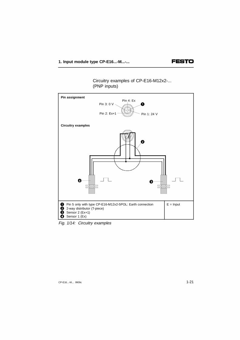
Circuitry examples of CP-E16-M12x2-... (PNP inputs)
Pin assignment
Circuitry examples
1234
Pin 5 only with type CP-E16-M12x2-5POL: Earth connection2-way distributor (T-piece)Sensor 2 (Ex+1)Sensor 1 (Ex)
E = Input
Fig. 1/14: Circuitry examples
34
2
Pin 1: 24 V
Pin 4: ExPin 3: 0 V
Pin 2: Ex+1
1
1. Input module type CP-E16...-M...-...
CP-E16...-M... 9909c 1-21

Internal layout of CP-E16N-M8 (NPN inputs)and CP-E16-M8-Z (NPN mode)
123
PLC/I-PC Ex (e.g. via field bus)Logic recognition ExGreen LED Ex
Fig. 1/15: Internal layout
24 V + 10/- 15 %
2
Pin 3
Pin 2
Pin 1
31
0 V
1. Input module type CP-E16...-M...-...
1-22 CP-E16...-M... 9909c

Circuitry examples of CP-E16N-M8 (NPN inputs)and CP-E16-M8-Z with NPN operation
Pin assignment
Circuitry examples
123
Three-wire sensor (negative switching)Two-wire sensor (negative switching)Contact
E = Input
Fig. 1/16: Circuitry examples
Pin 1: 24 V
Pin 3: 0 V
Pin 2: Ex
2 31
1. Input module type CP-E16...-M...-...
CP-E16...-M... 9909c 1-23

Internal layout of CP-E16N-M12x2 (NPN inputs)
123
PLC/I-PC Ex+1 (e.g. via field bus)Logic recognition Ex+1Green LED Ex+1
456
PLC/I-PC Ex (e.g. via field bus)Logic recognition ExGreen LED Ex
Fig. 1/17: Internal layout
24 V + 10/- 15 %
Pin 3
Pin 2
53
2
6
Pin 4
Pin 1
4
1
0 V
1. Input module type CP-E16...-M...-...
1-24 CP-E16...-M... 9909c

Circuitry examples of CP-E16N-M12x2 (NPN inputs)
Pin assignment
Circuitry examples
123
2-way connector (T piece)Sensor 2 (Ex+1) (negative switching)Sensor 1 (Ex) (negative switching)
E = Input
Fig. 1/18: Circuitry examples
1
23
Pin 1: 24 V
Pin 4: ExPin 3: 0 V
Pin 2: Ex+1
1. Input module type CP-E16...-M...-...
CP-E16...-M... 9909c 1-25

1.3.4 Connecting the input module
WARNINGPlease observe the maximum permitted stringlengths in each case. You will then avoid faults indata exchange between the input module and thehigher-order system (e.g. the field bus node).Use only the following cables for connecting themodules:
For connection to Max. permittedstring length
Cable type
Field bus nodewith CP connection
10 m - KVI-CP-1-...or- KVI-CP-2-...
(can be used as drag chain)
Axis interfacetype SPC-AIF-...
See manual forSPC200 type P.BE-SPC200-...
Powerboxtype CP-FB-TBOX-...
See manual forhigher-order system
The following functions are provided for the modulethrough the CP cable:
– Supply voltage for the internal electronics
– Data exchange connection
– For input modules not having a sensor supply con-nection: Operating voltage for the connected sensors.
1. Input module type CP-E16...-M...-...
1-26 CP-E16...-M... 9909c

Input modules can be connected to one of the follow-ing:
– the CP connection of the higher-order system (fieldbus node, axis interface or Powerbox)
– the CP connection of an output module
– the CP connection of a valve terminal
Further instructions can be found in the appropriatesystem manuals.
1. Input module type CP-E16...-M...-...
CP-E16...-M... 9909c 1-27

1.4 Instructions on commissioning
WARNINGPlease be careful if you modify the line assignmentof your CP system at a later stage.After saving the string assignment or hardware con-figuration, check the address assignment of yourhigher-order system before you start user programs.
You thereby avoid:
– addressing errors if CP modules are incorrectly fitted.
With the CP field bus node, the new string assignmentmust be saved if it has been modified (CP modulesadded or removed). To do this press the SAVE buttonon the node. Proceed as described in the manual "CPsystem, installation and commissioning."
With the SPC200, the new hardware configuration mustalso be saved if the string assignment has beenmodifed. Proceed here as described in the manual forthe SPC200 or for WinPISA.
The operating status of the input module is shown bythe status LED on the CP connection (see followingtable).
Status LED
1. Input module type CP-E16...-M...-...
1-28 CP-E16...-M... 9909c

Status LED Sequence Operating status Error treatment
LED lights up
Operating voltage applied None
LED is out
- Operating voltage notapplied or no connectionto higher-order system
orIn conjunction with CP node:- incorrect string assignment
ascertained during operation
In conjunction with SPC200:- see user manual for SPC200
• Check CP cable and operating voltageconnection on higher-order systemor
• Correct string assignment
• See user manualtype P.BE-SPC200
LED flashes
- Test phase after voltageis switched onor
- short circuit in sensor supply3)
orType CP-E16-M8-Z:- Sensor supply voltage too
low (< 17 V)or
In conjunction with CP node:- incorrect string assignment
when voltage is switched onIn conjunction with the SPC200:- see user manual for SPC200
• None
or• Eliminate short circuit
and delete error1)
or• Eliminate undervoltage
• Check string assignment2)
• See user manualtype P.BE-SPC200
1) For type CP-E16-M8-Z the error is automatically cleared. In other modules the error iscleared by disconnecting the input module from the branch or by resetting the supply voltage on the host system.
2) After changing the branch configuration (adding or removing CP modules) the new branch configuration must be stored by pressing the SAVE button on the node (see "CP System,Installation and Commissioning").
3) With type CP-E16-M8-Z the short-circuit LED for the appropriate input group lights up.
ON
OFF
ON
OFF
ON
OFF
1. Input module type CP-E16...-M...-...
CP-E16...-M... 9909c 1-29

Short circuit of the sensor supply on input moduleCP-E16-M8-Z
When there is a short circuit, the input module switchesoff the supply voltage for the corresponding input groupand reports the fault to the host system. The short cir-cuit LED on the corresponding input group lights up.
12
Input group 1 (upper row)Input group 2 (lower row)
3 Red LED indicating short circuit or loss ofsensor voltage (one LED per input group)
Fig. 1/19: Short circuit indicators for CP-E16-M8-Z
The status LEDs for the corresponding input group areswitched off and the corresponding inputs are at 0. Theother input group remains operational. After removingthe short circuit the error is self-clearing.
3
1
2
1. Input module type CP-E16...-M...-...
1-30 CP-E16...-M... 9909c

Short circuit in sensor supply for input moduleswithout sensor supply connection
If there is a short circuit, the input module will switch offthe power supply to the sensors and lock them in thisstate. It will also communicate the error to the higher-order system. The status LEDs will be switched off andthe inputs of the module will transmit a 0-signal. Whenthe short circuit has been eliminated, you can deletethis error as follows:
In conjunction with the CP field bus node:
• Disconnect the input module briefly from the line, or
• switch off the power supply at the node and thenswitch it on again.
In conjunction with the SPC200:
• Proceed as described in the user manual typeP.BE-SPC200.
If there is a fault in the CP module during operation,you can replace the module with one of the same type,even during operation.
Replacingthe CPmodule
PLEASE NOTEObserve here the instructions in the manual for thehigher-order system (e.g. CP system, CP field busnode, SPC200).
1. Input module type CP-E16...-M...-...
CP-E16...-M... 9909c 1-31

Next to the sensor connections there is/are one or twogreen LEDs. These indicate the state of the signal atthe relevant input. The meanings are as follows:
Status display
Status LED Sequence Status
LED lights up
1-signal
LED is out
0-signal
LED flashes
Only during switch-on phase:- if there is a 1-signal and- if there is a line assignment
error.
PLEASE NOTEIn conjunction with the CP field bus node:If there is a line assignment error during the switch-on phase, the CP node will switch the power supplyto the input module and also the power supply to theconnected sensors on and off cyclically. In this case,the status LEDs and the LEDs of the connectedsensors will therefore flash, providing they transmit a1-signal.
ON
OFF
ON
OFF
ON
OFF
1. Input module type CP-E16...-M...-...
1-32 CP-E16...-M... 9909c

1.5 Technical data
Technical data Type CP-E16-M8-Z positive-switching (PNP) or negative-switching (NPN) mode
Temperature range:- Operation- Storage/transport
- 5 °C... + 50 °C- 20 °C... + 70 °C
Relative humidity 95 % non condensing
Protection class as per EN 60529; plug connector attached or fitted with cover cap
IP65
Shock protection as per EN 60204/IEC 204
(Protection against direct and indirect contact) whenconnected to a PELV power supply (Protected Extra-Low Voltage)
Electromagnetic compatibility - Interference emission- Resistance to interference
Tested as per EN 55011 limit class BTested as per EN 50082-2
Digital inputs- Type
16 inputsas per IEC 1131-2 type 2 inputs24 V DC positive or negative-switching
- Logic level positive-switchingONOFF
- Logic level negative-switchingONOFF
PNP (referenced to 0 V):� 8.6 V� 6 VNPN (referenced to 24 V):� 6 V� 8.6 V
- Current consumption (at 24 V)(input current from sensorto input)
For "logic 1"Typ. 8 mA
- Response delay (at 24 V) Typ. 3 ms
Sensor supply VD 24 V � 25 % Max. 1 A per input group (electronic short circuitprotection per group)
Galvanic isolation None
Internal current consumption(electronics)
< 40 mA
1. Input module type CP-E16...-M...-...
CP-E16...-M... 9909c 1-33

Technical data Positive-switching input modules (NPN) without separate sensor supply connection
Types CP-E16-M8 andCP-E16-M12x2
Type CP-E16-M12x2-5POL
Temperature range:- Operation- Storage/transport
- 5 °C... + 50 °C- 20 °C... + 70 °C
Relative humidity 95 % non condensing
Protection class as per EN 60529; plug connector attached or fitted with cover cap
IP65
Shock protection as per EN 60204/IEC 204
(Protection against direct and indirect contact) whenconnected to a PELV power supply (Protected Extra-Low Voltage)
Electromagnetic compatibility - Interference emission
- Resistance to interference
Tested to EN 55011 limit class BTested to EN 50082-2
Tested to EN 55011 limit class BTested to EN 50082-2
Digital inputs- Type
16 inputsas per IEC 1131-2 type 2 inputs24 V DC positive-switching
16 inputsas per IEC 1131-2 type 2 inputs24 V DC negative-switching
- Logic level:ONOFF
> 11 V< 5 V
≥ 8.6 V≤ 6 V
- Current consumption (at 24 V)(input current from sensorto input)
For "logic 1"Typ. 8 mA
For "logic 1"Typ. 6 mA
- Response delay (at 24 V) Typ. 5 ms Typ. 3 ms
Sensor supply VD 24 V � 25 % Max. 0.5 A(electronic short circuit protection)
Galvanic isolation None
Internal current consumption (electronics)
< 40 mA Max. 90 mA
1. Input module type CP-E16...-M...-...
1-34 CP-E16...-M... 9909c

Technical data Negative-switching input modules (NPN)
Type CP-E16N-M8 and type CP-E16N-M12x2
Temperature range:- Operation- Storage/transport
- 5 °C ... + 50 °C- 20 °C ... + 70 °C
Relative humidity 95 % non condensing
Protection class as per EN 60 529;plug connector attached or fitted withcover cap
IP65
Shock protection as per EN 60204/ IEC 204
(Protection against direct and indirect contact)when connected to a PELV power supply(Protected Extra-Low Voltage)
Electromagnetic compatibility- Interference emission- Resistance to interference
Tested as per EN 55011 limit value class BTested as per EN 50082-2
Digital inputs- Type
16 inputs as per IEC 1131-2 type 2 inputs 24 V DC negative switching
- Logic level:ONOFF
< VD -11 V> VD - 5 V
- Current consumption (at 24 V)(input current from sensorto input)
For "logic 0"Typ. 8 mA
- Response delay (at 24 V) Typ. 5 ms
Sensor supply VD 24 V � 25 % Max. 0.5 A(electronic short circuit protection)
Galvanic isolation None
Internal current consumption (electronics)
Max. 90 mA
1. Input module type CP-E16...-M...-...
CP-E16...-M... 9909c 1-35

1. Input module type CP-E16...-M...-...
1-36 CP-E16...-M... 9909c

Chapter 2
Output module type CP-A08...-M12-...
2. Output module type CP-A08...-M12-...
CP-A08...-M12 9909c 2-1

Contents
Output module type CP-A08...-M12-...
2.1 Overview. . . . . . . . . . . . . . . . . . . . . . . . . . . . . . . . . . . . . . . . . . . 2-32.2 Fitting . . . . . . . . . . . . . . . . . . . . . . . . . . . . . . . . . . . . . . . . . . . . . 2-42.3 Installation. . . . . . . . . . . . . . . . . . . . . . . . . . . . . . . . . . . . . . . . . . 2-52.3.1 Connecting the actuators . . . . . . . . . . . . . . . . . . . . . . . . . . . . . . 2-62.3.2 Connecting the output module . . . . . . . . . . . . . . . . . . . . . . . . . 2-132.3.3 Connecting the load voltage. . . . . . . . . . . . . . . . . . . . . . . . . . . 2-142.4 Instructions on commissioning . . . . . . . . . . . . . . . . . . . . . . . . . 2-172.5 Technical specifications . . . . . . . . . . . . . . . . . . . . . . . . . . . . . . 2-20
2. Output module type CP-A08...-M12-...
2-2 CP-A08...-M12 9909c

2.1 Overview
Output module type CP-A08...-M12-... provides 8universally usuable digital outputs for controlling low-current consuming devices (bulbs, further valves etc).The following diagram shows the display and connect-ing elements on the output module.
1
234
Designation for output type- OUTPUT-P for PNP outputs- OUTPUT-N for NPN outputsCP connectionConnections for actuatorsYellow LED for status display(one LED per output)
567890
Status LED (green)Load voltage connectionProtective capRecess for inscription signs (IBS 6x10)Earth connectionType plate
Fig. 2/1: Display and connecting elements
DIAG
POWER
OUTPUT-P
0
3 4
56
7 8
90
1
2
2. Output module type CP-A08...-M12-...
CP-A08...-M12 9909c 2-3
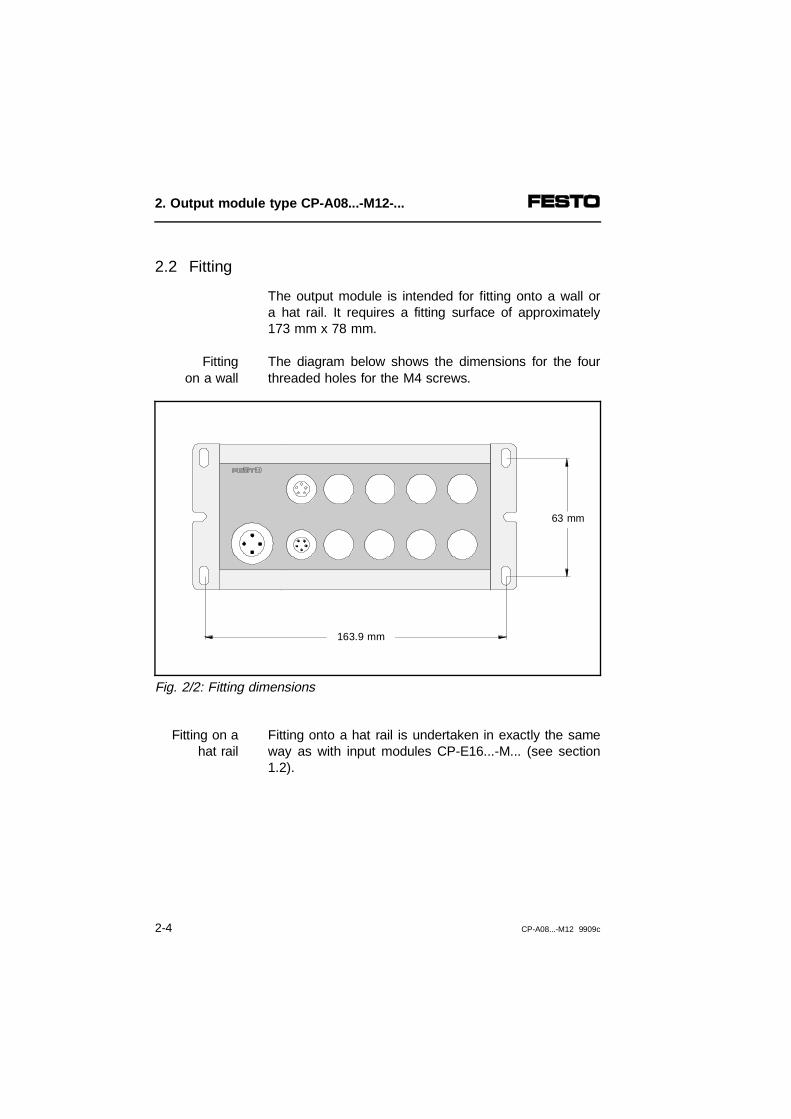
2.2 Fitting
The output module is intended for fitting onto a wall ora hat rail. It requires a fitting surface of approximately173 mm x 78 mm.
The diagram below shows the dimensions for the fourthreaded holes for the M4 screws.
Fittingon a wall
Fig. 2/2: Fitting dimensions
Fitting onto a hat rail is undertaken in exactly the sameway as with input modules CP-E16...-M... (see section1.2).
Fitting on ahat rail
63 mm
163.9 mm
2. Output module type CP-A08...-M12-...
2-4 CP-A08...-M12 9909c

2.3 Installation
WARNINGBefore undertaking maintenance work, switch off:• the load voltage supply to the relevant output
modules.Also switch off the following before undertaking installation work:• the voltage supply for the higher-order system• the power supply to all the output modules.
You thereby avoid:
• unintentional movements of the connected actuators.
• undefined switching states of the electronic compo-nents.
WARNINGConnect the earth cable on the side of the housing(see Fig. 2/1) with low impedance (short cable withlarge cross-sectional area) to the earth potential.In this way you can avoid interference caused byelectromagnetic influences.
2. Output module type CP-A08...-M12-...
CP-A08...-M12 9909c 2-5

2.3.1 Connecting the actuators
Use plugs with union nuts with M12 thread for connect-ing the actuators. Fasten the plugs with the aid of theunion nuts in order to avoid unintentional loosening e.g.due to vibration.
Seal the unused sensor connections with the protectivecaps supplied. Only then is compliance with class ofprotection IP65 ensured.
Pin assignment of the actuator connectionsCP-A08-M12-... (PNP outputs)
n.c. = not connected A = Output
Fig. 2/3: Pin assignment of output module CP-A08-M12
Ax+1
Pin 3: 0V
Pin 4: Ax
Pin 4: Ax+1
Pin 3: 0V
Ax
Pin 1: n.c.
Pin 1: n.c.
Pin 2: n.c.
Pin 2: n.c.
2. Output module type CP-A08...-M12-...
2-6 CP-A08...-M12 9909c

By means of internal connections, two outputs can beconnected to each of the output sockets 0, 2, 4 and 6on the CP output module type CP-A08-M12-5POL.
12
Pin 5: Earth connectionInternal connection in the module
A = Outputn.c. = not connected
Fig. 2/4: Pin assignment of output module CP-A08-M12-5POL
Ax+1
Pin 3: 0V
Pin 4: Ax
Pin 4: Ax+1
Pin 3: 0V
Ax
Pin 1: n.c.
Pin 1: n.c.
Pin 2: Ax+1
Pin 2: n.c.
1
2
1
2. Output module type CP-A08...-M12-...
CP-A08...-M12 9909c 2-7

Internal layout of CP-A08-M12-... (PNP outputs)
1234
Load voltage connectionPLC/IPC Ax (e.g. via field bus)Galvanic isolationWith type CP-A08-M12: not connectedWith type CP-A08-M12-5POL:- connection 0, 2, 4, 6: Ax+1- connection 1, 3, 5, 7: not connected
567
89
Yellow LEDGreen LEDDiagnosis • short circuit, overload
• load voltage failureActuator connectionPin 5 only with type CP-A08-M12-5POL:Earth connection
Fig. 2/5: Internal layout of output module CP-A08-M12-...
24 V ± 25 %Pin 2
Pin 4
Pin 3
Pin 1
Pin 1
Pin 4
Pin 3
Pin 2
0 V
2
3
4
4
7
6
1 8
9
5
4
2. Output module type CP-A08...-M12-...
2-8 CP-A08...-M12 9909c

Circuitry examples of CP-A08-M12-... (PNP outputs)
Pin assignment
Examples of circuitry
24VA = Outputn.c. = not connected
1
2
Pin 5 only with type CP-A08-M12-5POL:Earth connectionWith type CP-A08-M12: not connectedWith type CP-A08-M12-5POL:- connection 0, 2, 4, 6: Ax+1- connection 1, 3, 5, 7: not connected
345
Example 1Example 2Not permitted
Fig. 2/6: Circuitry examples of output module CP-A08-M12-...
Pin 1: n.c.
Pin 4: Ax+1
Pin 3: 0 V
Pin 2: 2
1
4 53
2. Output module type CP-A08...-M12-...
CP-A08...-M12 9909c 2-9

Pin assignment of the actuator connectionsCP-A08N-M12 (NPN outputs)
1
*)Earth connectionConsuming device/load must be supplied via this 24 V connectionn.c. = not connectedA = Output
Fig. 2/7: Pin assignment of output module CP-A08N-M12
Ax+1
Ax
Pin 2: 1
Pin 2: 1
Pin 3: n.c.
Pin 3: n.c.
Pin 4: Ax
Pin 4: Ax+1
Pin 1: 24 V*)
Pin 1: 24 V*)
2. Output module type CP-A08...-M12-...
2-10 CP-A08...-M12 9909c

Internal layout of CP-A08N-M12 (NPN outputs)
1234
Load voltage connectionPLC/I-PC Ax+1 (e.g. via field bus)Galvanic isolationNot connected
567
8
Yellow LEDGreen LEDDiagnosis • short circuit, overload
• load voltage failureActuator connection
Fig. 2/8: Internal layout of output module CP-A08N-M12
Pin 3
Pin 4
Pin 2
Pin 1
Pin 3
Pin 4
Pin 1
Pin 2
0 V
1
2
34
7 5
6
8
24 V ± 25 %
2. Output module type CP-A08...-M12-...
CP-A08...-M12 9909c 2-11

Circuitry examples of CP-A08N-M12 (NPN outputs)
Pin assignment
Circuitry examples
1234
Earth connectionExample 1Example 2Not permitted
A = Outputn.c. = not connected*) Consuming device/load must be supplied
via this 24 V connection
Fig. 2/9: Circuitry examples of output module CP-A08N-M12
Pin 1 : 24 V*)
Pin 4: Ax+1
Pin 3: n.c.
Pin 2: 1
3 42
2. Output module type CP-A08...-M12-...
2-12 CP-A08...-M12 9909c

2.3.2 Connecting the output module
WARNINGPlease observe the maximum permitted stringlengths. In this way you will avoid faults in data ex-change between the output module and the higher-order system (e.g. field bus node).Use only the following cables to connect the modules.
For connection to Max. permittedstring length
Cable type
Field bus nodewith CP connection
10 m - KVI-CP-1-...or- KVI-CP-2-...
(can be used asdrag chain)
Axis interfacetype SPC-AIF-...
See manual for theSPC200 typeP.BE-SPC200-...
Powerbox type CP-FB-TBOX-...
See manual for the higher-order system
Communication takes place via the CP cable and theoperating voltage for the internal electronics of the mo-dule is also supplied via the CP cable.
The output module is connected directly to the CP con-nection of the higher-order system (field bus node, axisinterface or Powerbox). Detailed instructions can befound in the relevant system manual.
2. Output module type CP-A08...-M12-...
CP-A08...-M12 9909c 2-13

2.3.3 Connecting the load voltage
WARNINGUse only power units which guarantee reliableisolation of the operating voltages as per IEC 742/EN 60742/VDE 0551 with at least 4 kV isolationresistance (protected extra low voltage, PELV).Switch power packs are permitted if they guaranteereliable isolation in accordance with EN 60950/VDE 0805.
By using PELV power units, protection against electricshock (protection against direct and indirect contact) inaccordance with EN 60204-1/IEC 204 is guaranteed onFesto valve terminals. Safety transformers with the ad-jacent designation must be used for supplying PELVnetworks. The valve terminals must be earthed in orderto ensure their function (e.g. EMC).
The connected actuators are supplied with + 24 V DCvia the load voltage connection on the output module.Use a cable with sufficiently large cross-sectional areafor the operating voltage.
2. Output module type CP-A08...-M12-...
2-14 CP-A08...-M12 9909c

The diagram below shows the pin assignment of theload voltage connection on the output module as wellas a connection example.
n.c.= not connected
123
Earth connection pin 4Earth connection on side of housingLoad voltage can be switched off separately; the operatingvoltage is supplied via the CP connection
Fig. 2/10: Pin assignment of load voltage connection
DIAG
POWER
OUTPUT-P
Pin 1:n.c.
Pin 4:1
Pin 3:0 V
Pin 2:24 V DC ± 25 %
2
3
2. Output module type CP-A08...-M12-...
CP-A08...-M12 9909c 2-15
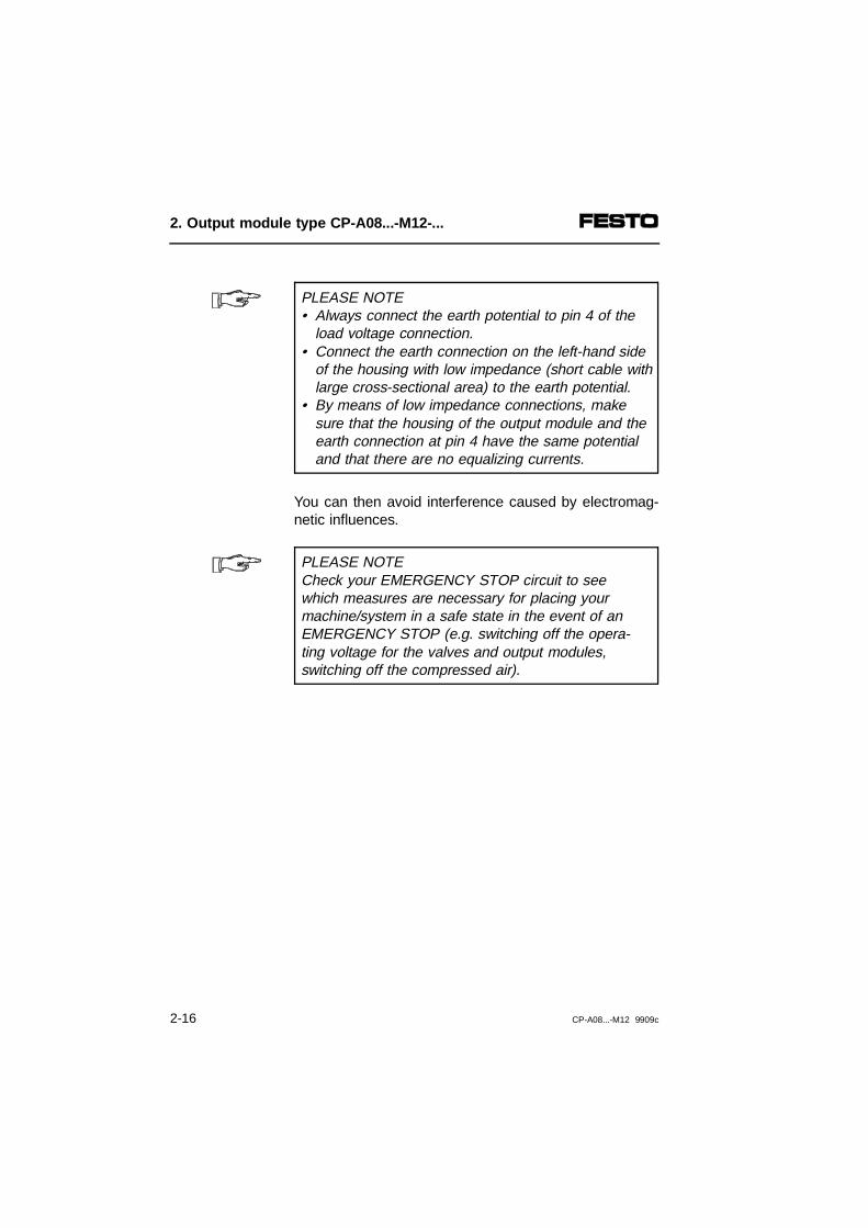
PLEASE NOTE• Always connect the earth potential to pin 4 of the
load voltage connection.• Connect the earth connection on the left-hand side
of the housing with low impedance (short cable withlarge cross-sectional area) to the earth potential.
• By means of low impedance connections, makesure that the housing of the output module and the earth connection at pin 4 have the same potentialand that there are no equalizing currents.
You can then avoid interference caused by electromag-netic influences.
PLEASE NOTECheck your EMERGENCY STOP circuit to seewhich measures are necessary for placing yourmachine/system in a safe state in the event of anEMERGENCY STOP (e.g. switching off the opera-ting voltage for the valves and output modules,switching off the compressed air).
2. Output module type CP-A08...-M12-...
2-16 CP-A08...-M12 9909c

2.4 Instructions on commissioning
WARNINGPlease be careful when modifying the string assign-ment at a later stage.After saving the string assignment/hardware configu-ration, check the address assignment of your higher-order system before starting user programs.
You can then avoid:
– addressing errors with incorrectly installed CPmodules.
With CP field bus nodes, the new string assignmentmust be saved if it has been modified (CP modulesadded or removed). To do this press the SAVE buttonon the node. Proceed here as described in the manual"CP system, installation and commissioning."
With the SPC200, the new hardware configuration mustalso be saved after the string assignment has beenmodified. Proceed here as described in the manual forthe SPC200 or for WinPISA.
The operating status of the output module is shown bythe status LED on the CP connection (see followingtable):
Status LED
2. Output module type CP-A08...-M12-...
CP-A08...-M12 9909c 2-17

Status LED Sequence Operating status Error treatment
LED lights up
Operating voltage applied None
LED is out
- Operating voltage notapplied or no connectionto node
orIn conjunction with the CPnode- incorrect string assignment
during operationIn conjunction with theSPC200- see user manual
for the SPC200
• Check CP cable andoperating voltage connection on the node(pin 1)or
• correct stringassignment
• See user manualtype P.BE-SPC200-...
LED flashesquickly
- Test phase when power supply is switched onor
- short circuit/overload on at least one output module
orIn conjunction with the CPnode- incorrect string assignment
when power supply is switched on
In conjunction with theSPC200- see user manual
for the SPC200
• None
or• eliminate short
circuit/overloadand reset output 1)
or
• check string assignment2)
• See user manualtype P.BE-SPC200-...
LED flashesslowly
Load voltage failure Restore load voltage
1) If there is a short circuit/overload, all outputs of the module will be switched offautomatically. The error must be eliminated when the outputs are reset e.g. by userprogram.
2) When the line assignment has been modified (CP modules added or removed), you muststore the new string assignment by pressing the SAVE button on the node.
ON
OFF
ON
OFF
ON
OFF
ON
OFF
2. Output module type CP-A08...-M12-...
2-18 CP-A08...-M12 9909c

If there is a short circuit/overload, the output module willswitch off all 8 outputs automatically and communicatethe error to the node. When the short circuit has beeneliminated, you can delete this error as follows:
Short circuit/overload
• Reset all 8 outputs (e.g. by means of user program)
If there is a fault on the CP module during operation,you can replace the module by another of the sametype during operation.
Replacingthe CPmodule
PLEASE NOTEObserve here the instructions in the manual for thehigher-order system (e.g. CP system, CP field busnode, SPC200).
There are two yellow LEDs next to the connections forthe actuators. These indicate the status of the signal atthe relevant output. The meanings are:
Statusdisplay
Status LED Sequence Status
LED lights up
Output supplies 1-signal
LED is out
Output supplies 0-signal
ON
OFF
ON
OFF
2. Output module type CP-A08...-M12-...
CP-A08...-M12 9909c 2-19

2.5 Technical specifications
Technical specifications Positive-switching output modules
Type CP-A08-M12 and type CP-A08-M12-5POL
Temperature range:- operation- storage/transport
- 5 °C ... + 50 °C- 20 °C ... + 70 °C
Relative humidity 95 % non condensing
Protection class as per EN 60529 Plug connector inserted or fitted with protectivecap: IP65
Protection against electric shock asper EN 60204-1/IEC 204
(Protection against direct and indirect contact) byconnecting to a PELV power unit (ProtectedExtra-Low Voltage)
Electromagnetic compatibility- interference emission- resistance to interference
Tested as per EN 55011 limit value class BTested as per EN 50082-2
Load voltage connection
- rated value(protected against incorrect polarity)
- tolerance
- residual ripple
- isolation resistance- internal current consumption of
electronic components
Electrically isolated load voltage via additionalM18 plug connector.24 V
± 25 %
4 Vpp (within tolerance)
500 V< 40 mA
Digital outputs- design - loading per digital output
8 outputsas per IEC 1131-2; 24 V DC positive switching 0.5 A
- electronic fuse(short circuit, overload)trigger currentresponse time
min. 750 mAmax. 1.5 ms
2. Output module type CP-A08...-M12-...
2-20 CP-A08...-M12 9909c

Technical specifications Negative-switching output modules
Type CP-A08N-M12
Temperature range:- operation- storage/transport
- 5 °C ... + 50 °C- 20 °C ... + 70 °C
Relative humidity 95 % non condensing
Protection class as per EN 60529 Plug connector inserted or fitted with protectivecap: IP65
Protection against electric shock asper EN 60204-1/IEC 204
(Protection against direct and indirect contact) byconnecting to a PELV power unit (Protected Extra-Low Voltage)
Electromagnetic compatibility- interference emission- resistance to interference
Tested as per EN 55011 limit value class ATested as per EN 50082-2
Load voltage connection
- rated value(protected against incorrect polarity)
- tolerance
- residual ripple
- isolation resistance- internal current consumption of
electronic components
Electrically isolated load voltage via additionalM18 plug connector.24 V
± 25 %
4 Vpp (within tolerance)
500 V< 40 mA
Digital outputs- design
- loading per digital output
8 outputsas per IEC 1131-2; 24 V DC negative switching 0.5 A
- electronic fuse(short circuit, overload)trigger current response time
typ. 1 Amax. 1.5 ms
2. Output module type CP-A08...-M12-...
CP-A08...-M12 9909c 2-21

2. Output module type CP-A08...-M12-...
2-22 CP-A08...-M12 9909c

Appendix A
Index
A. Index
CP..EA 9909c A-1

Index
AActuators
connecting . . . . . . . . . . . . . . . . . . . . . . . . . . . . . . 2-6
CCP module
replace during operation . . . . . . . . . . . . . . . . . . 2-19
DDesignated use . . . . . . . . . . . . . . . . . . . . . . . . . . . . . . IV
FFitting
input module . . . . . . . . . . . . . . . . . . . . . . . . . . . . 1-6output module . . . . . . . . . . . . . . . . . . . . . . . . . . . 2-4
IInformation on this manual. . . . . . . . . . . . . . . . . . . . . VIIInput module . . . . . . . . . . . . . . . . . . . . . . . . . . . . . . 1-32
circuitry examples CP-E16-M8 (PNP) . . . . . . . . 1-19circuitry examples CP-E16-M12x2-... . . . . . . . . 1-21circuitry examples CP-E16N-M12x2 . . . . . . . . . 1-25circuitry examples CP-E16N-M8-... (NPN) . . . . 1-23connect to node . . . . . . . . . . . . . . . . . . . . . . . . . 1-26fitting on a wall . . . . . . . . . . . . . . . . . . . . . . . . . . . 1-6fitting onto a hat rail . . . . . . . . . . . . . . . . . . . . . . . 1-8internal layout CP-E16-M12x2-.... . . . . . . . . . . . 1-20internal layout CP-E16-M8-... (PNP) . . . . . . . . . 1-18internal layout of CP-E16N-M12x2 . . . . . . . . . . 1-24internal layout of CP-E16N-M8-... (NPN) . . . . . 1-22
A. Index
A-2 CP..EA 9909c

LLED
status display of input module. . . . . . . . . . . . . . 1-32status display of output module. . . . . . . . . . . . . 2-19status LED input module . . . . . . . . . . . . . . . . . . 1-28status LED output module. . . . . . . . . . . . . . . . . 2-17
OOutput module
- connect to node. . . . . . . . . . . . . . . . . . . . . . . . 1-26- replace during operation . . . . . . . . . . . . . . . . . 1-31circuitry examples CP-A08-M12 . . . . . . . . . . . . . 2-9circuitry examples CP-A08N-M12 . . . . . . . . . . . 2-12fitting on a hat rail . . . . . . . . . . . . . . . . . . . . . . . . 2-4fitting on a wall. . . . . . . . . . . . . . . . . . . . . . . . . . . 2-4internal layout CP-A08-M12-... . . . . . . . . . . . . . . 2-8internal layout CP-A08N-M12 . . . . . . . . . . . . . . 2-11
PPictograms . . . . . . . . . . . . . . . . . . . . . . . . . . . . . . . . . . VIPin assignment
inputs . . . . . . . . . . . . . . . . . . . . . . . . . . . . . . . . . 1-16NPN output . . . . . . . . . . . . . . . . . . . . . . . . . . . . 2-10operating voltage connection of CP-A08...-M12 . . . . . . . . . . . . . . . . . . . . . . . . . . 2-15PNP outputs. . . . . . . . . . . . . . . . . . . . . . . . . . . . . 2-6
SSensors
circuitry examples CP-E16-M8-... (PNP). . . . . . 1-19circuitry examples CP-E16N-M8-... (NPN) . . . . 1-23circuitry examples CP-E16-M12x2 . . . . . . . . . . 1-21circuitry examples CP-E16N-M12x2 . . . . . . . . . 1-25connecting . . . . . . . . . . . . . . . . . . . . . . . . . . . . . 1-15
A. Index
CP..EA 9909c A-3

Short circuitoverload . . . . . . . . . . . . . . . . . . . . . . . . . . . . . . . 2-19sensor supply. . . . . . . . . . . . . . . . . . . . . . 1-30, 1-31sensor supply CP-E16-M8-Z . . . . . . . . . . . . . . . 1-30
Status LEDinput module . . . . . . . . . . . . . . . . . . . . . . . . . . . 1-28output module . . . . . . . . . . . . . . . . . . . . . . . . . . 2-17
TTarget group . . . . . . . . . . . . . . . . . . . . . . . . . . . . . . . . . VTechnical data
input module CP-E16-M...-... (PNP) . . . . . . . . . 1-34input module CP-E16-M8-Z (PNP/NPN) . . . . . . 1-33input module CP-E16N-M... (NPN) . . . . . . . . . . 1-35output module CP-A08...-M12-... (PNP) . . . . . . 2-20output module CP-A08N-M12 (NPN) . . . . . . . . 2-21
UUser instructions . . . . . . . . . . . . . . . . . . . . . . . . . . . . . V
A. Index
A-4 CP..EA 9909c