Embed Size (px)
Citation preview
Compact Inverter TOSVERT
.
Environment-friendly, Handy Inverter — All Models, EMI Noise Filter Inside
1-phase 200V 0.2kW to 2.2kW3-phase 200V 0.2kW to 15kW3-phase 400V 0.75kW to 15kW
Industrial Equipment Department 1-1,Shibaura 1-chome, Minato-ku, Tokyo 105-8001,Japan Tel: (03)3457-4911 Fax: (03)5444-9268
TOSHIBA CORPORATION
Printed in Japan03-5(AB)6491A
Precautions!
To users of our inverters: Our inverters are designed to control the speeds of three-phase induction motors for general industry.
For further information, please contact your nearest Toshiba Representative or International Operations-Producer Goods.The information in this brochure is subject to change without notice.
* Read the instruction manual before installing or operating the inverter unit and store it in a safe place for reference.* When using our inverters for equipment such as nuclear power control equipment, aviation and space flight control equipment, traffic
equipment, and safety equipment, and there is a risk that any failure or malfunction of the inverter could directly endanger human life or cause injury, please contact our headquarters, branch, or office printed on the front and back covers of this catalogue. Such applications must be studied carefully.
* When using our inverters for critical equipment, even though the inverters are manufactured under strict quality control always fit your equipment with safety devices to prevent serious accident or loss should the inverter fail (such as failure to issue an inverter trouble signal).
* Do not use our inverters for any load other than three-phase induction motors.* None of Toshiba, its subsidiaries, affiliates or agents, shall be liable for any physical damages, including, without limitation,malfunction,
anomaly, breakdown or any other problem that may occur to any apparatus in which the Toshiba inverter is incorporated or to any equipment that is used in combination with the Toshiba inverter. Nor shall Toshiba, its subsidiaries, affiliates or agents be liable for any compensatory damages resulting from such utilization, including compensation for special,indirect, incidental, consequential, punitive or exemplary damages, or for loss of profit, income or data, even if the user has been advised or apprised of the likelihood of the occurrence of such loss or damages.
.
N1971
Contents
Flexible SelectionsFor System Designers ...
Easy InstallationFor Manufacturers ...
Easy SettingFor Users ...
Major World Standard
ISO 9001: VF-S9 series is manufactured at the works, which has received the international quality assurance standard ISO 9001 certification.
The works producing the VF-S9 series is registered as an environment management system factory specified by ISO 14001.
Excellent basic performance and diverse functions allow operations as needed.
Users can easily make settings and operate reliably.
EMI noise, audible noise, and installation space problems are solved.
Sensorless vector control provides the startup torque of 150% or more. The “Auto-tuning function” allows setting motor constants without rotating the motor.
Wide capacity range (0.2 to 15 kW) is provided even for this compact class.
Compatible with various power voltages. The single-phase input model inputs 200V to 240V, the three-phase 400V model inputs380V to 500V.
The control circuit I/O logic (Sink/Source) is switched by one-touch operation. Many types of programmable controllers are easily connected.
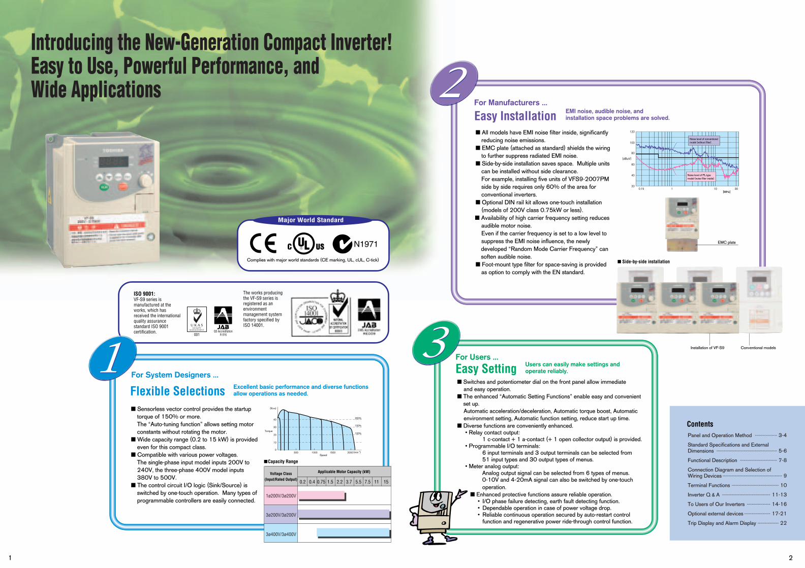
All models have EMI noise filter inside, significantly reducing noise emissions.
EMC plate (attached as standard) shields the wiring to further suppress radiated EMI noise.
Side-by-side installation saves space. Multiple units can be installed without side clearance. For example, installing five units of VFS9-2007PM side by side requires only 60% of the area for conventional inverters.
Optional DIN rail kit allows one-touch installation (models of 200V class 0.75kW or less).
Availability of high carrier frequency setting reduces audible motor noise. Even if the carrier frequency is set to a low level to suppress the EMI noise influence, the newly developed “Random Mode Carrier Frequency” can soften audible noise.
Foot-mount type filter for space-saving is providedas option to comply with the EN standard.
Switches and potentiometer dial on the front panel allow immediate and easy operation.
The enhanced “Automatic Setting Functions” enable easy and convenient set up. Automatic acceleration/deceleration, Automatic torque boost, Automatic environment setting, Automatic function setting, reduce start up time.
Diverse functions are conveniently enhanced. • Relay contact output:
1 c-contact + 1 a-contact (+ 1 open collector output) is provided. • Programmable I/O terminals:
6 input terminals and 3 output terminals can be selected from 51 input types and 30 output types of menus.
• Meter analog output:Analog output signal can be selected from 6 types of menus. 0-10V and 4-20mA signal can also be switched by one-touchoperation.
Enhanced protective functions assure reliable operation. • I/O phase failure detecting, earth fault detecting function. • Dependable operation in case of power voltage drop. • Reliable continuous operation secured by auto-restart control
function and regenerative power ride-through control function.
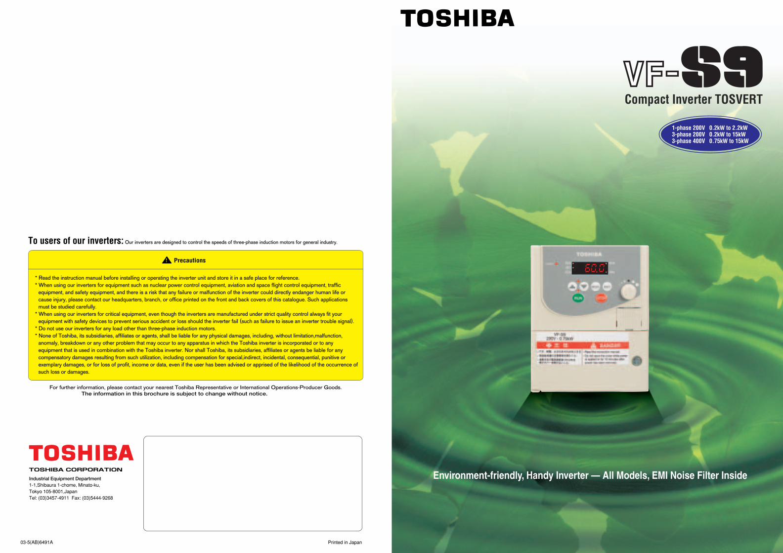
Complies with major world standards (CE marking, UL, cUL, C-tick)
Capacity Range
Side-by-side installation
Voltage Class(Input/Rated Output)
Applicable Motor Capacity (kW)
0.2 0.4 0.75 1.5 2.2 3.7 5.5 7.5 11 15
Noise level of conventional model (without filter)
Noise level of PL-type model (noise filter inside)
[MHz]
1 2
Introducing the New-Generation Compact Inverter!Easy to Use, Powerful Performance, and Wide Applications
Torque
Speed
Panel and Operation Method
Standard Specifications and External Dimensions
Functional Description
Connection Diagram and Selection of Wiring Devices
Terminal Functions
Inverter Q & A
To Users of Our Inverters
Optional external devices
Trip Display and Alarm Display
.................. 3-4
................................................. 5-6
.............................. 7-8
................................................ 9
...................................... 10
....................................... 11-13
................... 14-16
..................... 17-21
................. 22
[dBuV]
120
100
80
60
40
20
(N·m)
40
30
20
10
0500 1000 1500 2000 (min-1)
200%
150%
100%
0.15 1 10 30
1ø200V/3ø200V
3ø200V/3ø200V
3ø400V/3ø400V
EMC plate
Installation of VF-S9 Conventional models

Panel and Operation Method
Power ONMonitoring
Operating
3 4
Displays when the power is ON.
Displays when the standard setting ( ) is entered.
Select the base motor frequency. ( or )
Displays during frequency setting, and upon completion.
1 Displays “ ”
1 Operates TOSVERT at the frequency set with the potentiometer.
1 Displays operation frequency.
2 Displays the motor rotating direction.
3 Displays operation frequency command value.
4 Displays load current in (%/ampere)
5 Displays operation frequency (returns to the beginning).
2 Changes the frequency.
3 Decelerates and stops the motor.
ENT
.
Charge lamp Connection diagram label
Terminal board cover
Control circuit terminals
Connector of common serial communication/Extension panel/parameter writer
Logic switching/voltage-current output switching
Main circuit terminals (connect to power supply)
Main circuit terminals (connect to a motor)
Grounding terminal ( )
Attachment for EMC plate
Up/down key
LED display
Monitor key
Enter key
Potentiometer
STOP key
RUN key
Pressing the MON (monitor) key ...
Pressing the RUN key and turning the potentiometer dial ...
Pressing the MON (monitor) key twice ...
Press the UP key ...
Press the UP key ... Turning the potentiometer dial ...
Pressing the STOP key ...
Pressing key until “ ” is displayed ...
Press the ENTER key ...
Press the ENTER key after setting a value with the UP/DOWN key ...
2 Displays “ ”
4 Displays “ ” and the setting value alternately, and then the setting is complete.
3 Displays the setting.
.
.
MON
ENT
RUN
MON MON
MONSTOP… …
Pressing the UP key displays various data such as input voltage, output voltage, input/output terminal status.Pressing the MON (monitor) key ...
Standard Setting ( )
Setting
=
Type Form
SV F 9 S 2 0 0 7 P L W N
TOSVERTVF-S9 Series
S; 1-phaseNone: 3-phase
2: 200V to 240V(200V to 230V)
4: 380V to 500V
L: High-attenuation EMI filter inside
M: Standard EMI filter inside
Note) 1
WN: negativeWP: positiveAN: negativeNote) 2
P: Provided
002: 0.2kW004: 0.4kW007: 0.75kW015: 1.5kW022: 2.2kW037: 3.7kW055: 5.5kW075: 7.5kW110: 11kW150: 15kW
Note) 1. L:Standard model without optional filter conform to “EN55011 Group 1 Class A” Note) 2. Interface logic can be switched easily.With Foot-mounted noise filter conform to “EN55011 Group 1 Class B”
M:With Foot-mounted noise filter conform to “EN55011 Group 1 Class A”
In this mode, you can monitor the operational status of the inverter. To display the operation status during normal operation:Press the key twice.
Setting procedure (eg. operation at 60Hz)
.
.
.
.
.
.
Parameter setting mode
Operation frequency
Direction of rotation
Operation frequency command
Load current
Input voltage
Output voltage
Input terminal
Output terminal
MON
Item displayed
Key operated LED display
The operation frequency is displayed (during operation). (When the standard monitor display selection parameter is setat 0 [operation frequency])
The first basic parameter “Automatic acceleration/deceleration ( )” is displayed.
The operation frequency is displayed (during operation).
The direction of rotation is displayed. ( : forward run, : reverse run)
The operation frequency command value is displayed.
The inverter output current (load current) is displayed.
The inverter input voltage is displayed. (Default setting: unit %)
The inverter output voltage is displayed. (Default setting: unit %)
The ON/OFF status of each of the control signal input terminals (F, R, RST, S1, S2 and S3) is displayed in bits.
The ON/OFF status of each of the control signal output terminals (RY, OUT and FL) is displayed in bits.
Description Item displayed
Key operated LED display Description
MON
MON
.
. .
.
.
.
Model name
Number of power phases
Input voltage
Applicable motor capacityAdditional functions
Interface logic(Shipment setting)
Operation panel
Contents of the product code
Monitoring Status monitor mode
ON:
OFF:S3
S2S1
FRRST.
ENT
ON:
OFF:
FL RYOUT
CPU version The version of the CPU is displayed.
Memory version The version of the memory mounted is displayed.
Past trip 1 Past trip 1 (displayed alternately at 0.5-sec. intervals)
Past trip 2 Past trip 2 (displayed alternately at 0.5-sec. intervals)
MON
Past trip 3 Past trip 3 (displayed alternately at 0.5-sec. intervals)
Past trip 4 Past trip 4 (displayed alternately at 0.5-sec. intervals)
Cumulative operation time
The cumulative operation time is displayed. (0.01 corresponds to 1 hours.)
Torque current The torque current is displayed in %.
PI feedbackThe PI feedback value is displayed. (Unit: processed amount)
Inverter load factor The inverter load factor is displayed in %.
The overload factor of the braking resistor is displayed in %.
PBR overload factor
The inverter output power is displayed in %.Output power
The operation frequency is displayed (during operation).Default
display mode
Note) 1. With the current unit selection parameter or voltage unit selection parameter, you can choose between percentage and ampere (A) for current or between percentage and volt (V) for voltage, respectively.
=
.
Standard Specifications and External Dimensions
5 6
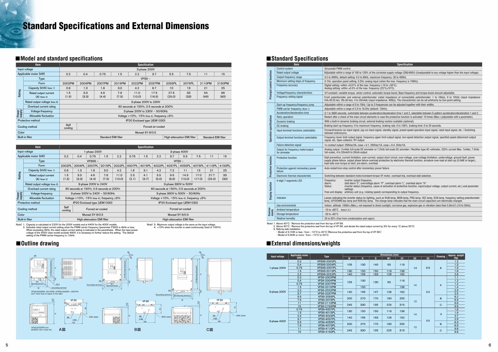
Standard Specifications
External dimensions/weights
Sinusoidal PWM controlAdjustable within a range of 100 to 120% of the corrected supply voltage (200/400V) (Unadjustable to any voltage higher than the input voltage).
Digital setting: within ±0.01% of the max. frequency (-10 to +50°C).Analog setting: within ±0.5% of the max. frequency (25°C±10°C).
V/f constant, variable torque, vector control, automatic torque boost, Base frequency and torque boost amount adjustable.
Front potentiometer and external potentiometer (rated impedance of connectable potentiometer: 1 to 10kΩ), 0 to 10Vdc (input impedance: VIA=30.55 kΩ, VB=30 kΩ), 4 to 20mAdc (input impedance: 400Ω), The characteristic can be set arbitrarily by two-point setting.
Adjustable within a range of 0 to 10Hz / Up to 3 frequencies can be adjusted together with their widths.Adjustable within a range of 2.0 to 16.5Hz (default: 12kHz).
0.1 to 3600 seconds, switchable between acceleration/deceleration time 1 and 2, selectable between S-pattern acceleration/deceleration 1 and 2.
With a built-in dynamic braking circuit, external braking resistor available (optional).
Braking start-up frequency: 0 to maximum frequency, braking rate: 0 to 100%, braking time: 0 to 20 seconds.
Frequency lower limit output signal, frequency upper limit output signal, low-speed detection output signal, specified speed attainment output signal, etc. Open collector, RY output.
Analog output: (1mAdc full-scale DC ammeter or 7.5Vdc full-scale DC ammeter / Rectifier-type AC voltmeter, 225% current Max. 1mAdc, 7.5Vdc full-scale), 4 to 20mA/0 to 20mA output.
1c-contact output: 250Vac/2A, cosø = 0.1, 250Vac/1A, cosø = 0.4, 3Vdc/1A.
Forward/reverse run input signal, jog run input signal, standby signal, preset-speed operation input signal, reset input signal, etc. / Switching between sink/source.
0.5 to 400Hz, default setting: 0.5 to 60Hz, maximum frequency: 30 to 400Hz.0.1Hz: operation panel setting, 0.2Hz: analog input (when the max. frequency is 100Hz).
Control systemRated output voltage
Output frequency rangeMinimum setting steps of frequencyFrequency accuracy
Voltage/frequency characteristicsFrequency setting signal
Start-up frequency/frequency jumpPWM carrier frequency (Note 1)
Acceleration/deceleration time
DC braking
Input terminal functions (selectable) Output terminal functions (selectable)
Failure detection signal
Stall prevention, current limitation, over-current, output short circuit, over-voltage, over-voltage limitation, undervoltage, ground fault, power supply phase failure, output phase failure overload protection by electronic thermal function, armature over-load at start-up (5.5kW or larger), load-side over-torque at start, pre-alarm, overheat.
Frequency: inverter output frequency.Alarm: stall alarm "C", overvoltage alarm “P”, overload alarm "L", overheat alarm “H”.Status: inverter status (frequency, cause of activation of protective function, input/output voltage, output current, etc.) and parameter
settings.Free-unit display: arbitrary unit (e.g. rotating speed) corresponding to output frequency.
Protective function
4-digit 7-segments LED
Lamps indicating the inverter status by lighting, such as RUN lamp, MON lamp, PRG lamp, VEC lamp, ECN lamp, frequency setting potentiometer lamp, UP/DOWN key lamp and RUN key lamp. The charge lamp indicates that the main circuit capacitors are electrically charged.
Indicator
Auto-restart/non-stop control after momentary power failure.Protection against momentary power failure
Switching between standard motor/constant-torque VF motor, overload trip, overload stall selection.Electronic thermal characteristic
Output for frequency meter/output for ammeter
Restart after a check of the main circuit elements in case the protective function is activated: 10 times (Max.) (adjustable with a parameter).Retry operation
Dynamic braking
Model and standard specificationsItem Specification Item Specification
3-phase 200V
VFS9 –
3-phase 200V to 230V
60 seconds at 150%, 0.5 seconds at 200%
3-phase 200V to 230V – 50/60Hz
Voltage +10%, -15% Note 4), frequency ±5%
IP20 Enclosed type (JEM1030)
Munsel 5Y-8/0.5
Selfcooling Forced air-cooled
Standard EMI filter High-attenuation EMI filter
0.2
2002PM
0.6
Standard EMI filter
1.5(1.5)
3.3(3.3)
4.8(4.4)
7.8(7.5)
11.0(10.0)
17.5(16.5)
27.5(25.0)
33(33)
54(49)
66(60)
2004PM
1.3
2007PM
1.8
2015PM
3.0
2022PM
4.2
2037PM
6.7
2055PL
10
2075PL
13
2110PM
21
2150PM
25
0.4 0.75 1.5 2.2 3.7 5.5 7.5 11 15
Input voltage
Applicable motor (kW)
Protective method
Cooling method
Color
Built-in filter
Type
Form
Capacity (kVA) Note 1)
Rated output voltage Note 3)
Overload current rating
Voltage-frequency
Allowable fluctuation
Rated output current(A) Note 2)
1-phase 200V
3-phase 200V to 240V
60 seconds at 150%, 0.5 seconds at 200%
3-phase 200V to 240V – 50/60Hz
Voltage +10%, -15% Note 4), frequency ±5%
IP20 Enclosed type (JEM1030)
Munsel 5Y-8/0.5
High-attenuation EMI filter
3-phase 380V to 500V
60 seconds at 150%, 0.5 seconds at 200%
3-phase 380V to 500V – 50/60Hz
Voltage +10%, -15% Note 4), frequency ±5%
IP20 Enclosed type (JEM1030)
Munsel 5Y-8/0.5
High-attenuation EMI filter
3-phase 400V
VFS9S – VFS9 –
0.2 0.4 0.75 1.5 2.2 0.75 1.5 2.2 3.7 5.5 7.5 11 15
2002PL
0.6
1.5(1.5)
2004PL
1.3
3.3(3.3)
2007PL
1.8
4.8(4.4)
2015PL
3.0
7.8(7.5)
2022PL
4.2
11.0(10.0)
4007PL
1.8
2.3(2.1)
4015PL
3.1
4.1(3.7)
4022PL
4.2
5.5(5.0)
4037PL
7.2
4055PL
11
4075PL
13
4110PL
21
4150PL
25
9.5(8.6)
14.3(13.0)
17.0(17.0)
27.7(25.0)
33(30)
Note) 1. Capacity is calculated at 220V for the 200V models and at 440V for the 400V models. 2. Indicates rated output current setting when the PWM carrier frequency (parameter F300) is 4kHz or less.
When exceeding 4kHz, the rated output current setting is indicated in the parenthesis. When the input power voltage of the 400V class model exceeds 480V, it is necessary to further reduce the setting. The default setting of the PWM carrier frequency is 12kHz.
Note) 3. Maximum output voltage is the same as the input voltage. 4. ±10% when the inverter is used continuously (load of 100%).
Ratin
gPo
wer
supp
ly
Input voltage
Applicable motor (kW)
Protective method
Cooling method
Color
Built-in filter
Type
Form
Capacity (kVA) Note 1)
Rated output voltage Note 3)
Overload current rating
Voltage-frequency
Allowable fluctuation
Rated output current(A) Note 2)Ra
ting
Pow
ersu
pply
Item Specification
Selfcooling Forced air-cooledForced air-cooled
Prin
cipa
l con
trol f
unct
ions
Oper
atio
n sp
ecifi
catio
nsPr
otec
tive
func
tion
Disp
lay
func
tion
Indoor, altitude: 1000m (Max.), not exposed to direct sunlight, corrosive gas, explosive gas or vibration (less than 5.9m/s2) (10 to 55Hz).
-10 to +60°C Note)1.2.3
-20 to +65°C
20 to 93% (free from condensation and vapor).
Use environments
Ambient temperature
Storage temperature
Relative humidity
Envi
ron-
men
ts
Note) 1. Above 40°C : Remove the protective seal from the top of VF-S9. 2. Above 50°C : Remove the protective seal from the top of VF-S9, and derate the rated output current by 3% for every °C above 50°C 3. Side-by-side installation
・Model of 3.7kW or less : from —10°C to 40°C (Remove the protective seal from the top of VF-S9.)・Model of 5.5kW or more : from —10°C to 50°C
Outline drawing
0.20.4
0.751.52.20.20.4
0.751.52.23.75.57.51115
0.751.52.23.75.57.51115
VFS9S-2002PLVFS9S-2004PLVFS9S-2007PLVFS9S-2015PLVFS9S-2022PLVFS9-2002PMVFS9-2004PMVFS9-2007PMVFS9-2015PMVFS9-2022PMVFS9-2037PMVFS9-2055PLVFS9-2075PLVFS9-2110PMVFS9-2150PMVFS9-4007PLVFS9-4015PLVFS9-4022PLVFS9-4037PLVFS9-4055PLVFS9-4075PLVFS9-4110PLVFS9-4150PL
130
150195
130
150
195
270
330
150
195
270
330
105
130140
105
140
200
245
130
140
200
245
140
150163
130
147
170
195
150
163
170
195
118
138182
118
138
182
255
315
138
182
255
315
12
14
12
93
118126
93
126
180
225
118
126
180
225
1.21.31.31.82.81.11.21.21.42.32.56.26.39.89.91.81.92.72.96.36.39.89.8
A
A
B
C
B
C
1-phase 200V
3-phase 200V
3-phase 400V
Input voltage Applicable motor(kW) Type
HW D H1 H2Approx. weight
(kg)W1 D2Drawing
Dimensions (mm)
A
8.5
8.5
8.5
14
14
W
B図
D2
H
R3
H2
W1 (Mounting dimension)
EMC plateEMC plateEMC plate
H1(Mounting dimension)
D
W
D
C図
R3
H2
H
W1(Mounting dimension)
H1(Mounting dimension)
D2
91
9162
M5M5 M5
4-M4 4-M4
198 1984-M4
102
VF-S9 VF-S9 VF-S9
VFS9-2002PM and 2002PL don't have fan.
VFS9-2002PM~2015PM, VFS9S-2002PL~2007PL don't have hole of upper to the right.
A図
W
H
φ5
R2.5
Grounding terminal
H2
W1 (Mounting dimension)
H1(Mounting dimension)
D
D2
R3
R7
9
R3
R7
9
Grounding terminal
Grounding terminal
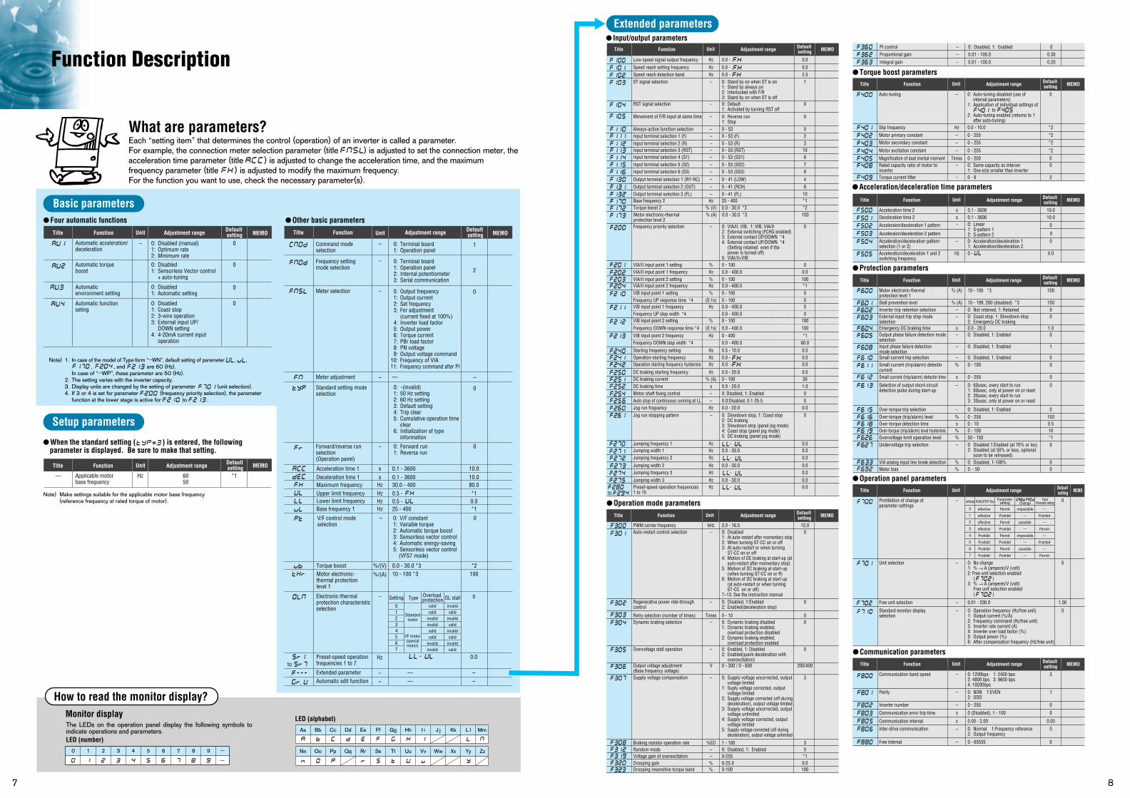
Extended parameters Input/output parameters
to
Torque boost parameters
Low-speed signal output frequency Hz 0.0 - 0.0
Auto-tuning – 0: Auto-tuning disabled (use of 0internal parameters)
1: Application of individual settings of to
2: Auto-tuning enabled (returns to 1 after auto-tuning)
Slip frequency Hz 0.0 - 10.0 *2
Motor primary constant – 0 - 255 *2Motor secondary constant – 0 - 255 *2
Motor excitation constant – 0 - 255 *2
Torque current filter – 0 - 8 2
Magnification of load inertial moment Times 0 - 200 0Rated capacity ratio of motor to – 0: Same capacity as interver 0inverter 1: One-size smaller than inverter
Title Function Adjustment range Default settingUnit MEMO
Speed reach setting frequency Hz 0.0 - 0.0Speed reach detection band Hz 0.0 - 2.5ST signal selection – 0: Stand by on when ST is on 1
1: Stand by always on2: Interlocked with F/R3: Stand by on when ST is off
RST signal selection – 0: Default 01: Activated by turning RST off
– 0: Reverse run 01: Stop
Always-active function selection – 0 - 53 0
Movement of F/R input at same time
Input terminal selection 1 (F) – 0 - 53 (F) 2Input terminal selection 2 (R) – 0 - 53 (R) 3Input terminal selection 3 (RST) – 0 - 53 (RST) 10Input terminal selection 4 (S1) – 0 - 53 (SS1) 6Input terminal selection 5 (S2) – 0 - 53 (SS2) 7Input terminal selection 6 (S3) – 0 - 53 (SS3) 8
Output terminal selection 1 (RY-RC) – 0 - 41 (LOW) 4Output terminal selection 2 (OUT) – 0 - 41 (RCH) 6Output terminal selection 3 (FL) – 0 - 41 (FL) 10Base frequency 2 Hz 25 - 400 *1Torque boost 2 % (V) 0.0 - 30.0 *3 *2
Frequency priority selection – 0: VIA/II, VIB, 1: VIB, VIA/II 02: External switching (FCHG enabled) 3: External contact UP/DOWN *44: External contact UP/DOWN *4
(Setting retained even if the power is turned off)
5: VIAI/II+VIB
Motor electronic-thermal % (A) 0.0 - 30.0 *3 100protection level 2
VIA/II input point 1 setting % 0 - 100 0VIA/II input point 1 frequency Hz 0.0 - 400.0 0.0
Starting frequency setting Hz 0.5 - 10.0 0.5Operation starting frequency Hz 0.0 - 0.0Operation starting frequency hysterisis Hz 0.0 - 0.0
DC braking starting frequency Hz 0.0 - 20.0 0.0
DC braking time s 0.0 - 20.0 1.0Motor shaft fixing control – 0: Disabled, 1: Enabled 0Auto stop of continuous running at LL – 0.0:Disabled, 0.1-25.5 0Jog run freguency Hz 0.0 - 20.0 0.0
Jumping frequency 1 Hz - 0.0Jumping width 1 Hz 0.0 - 30.0 0.0
Jumping width 2 Hz 0.0 - 30.0 0.0
Jumping width 3 Hz 0.0 - 30.0 0.0Preset-speed operation frequencies Hz - 0.01 to 15
Jumping frequency 2 Hz - 0.0
Jumping frequency 3 Hz - 0.0
Jog run stopping pattern – 0: Slowdown stop, 1: Coast stop 02: DC braking3: Slowdown stop (panel jog mode) 4: Coast stop (panel jog mode)5: DC braking (panel jog mode)
DC braking current % (A) 0 - 100 30
VIA/II input point 2 setting % 0 - 100 100
VIB input point 1 setting % 0 - 100 0Frequency UP response time *4 (0.1s) 0 - 100 0
Frequency UP step width *4 0.0 - 400.0 0
Frequency DOWN step width *4 0.0 - 400.0 60.0
VIB input point 1 frequency Hz 0.0 - 400.0 0
Frequency DOWN response time *4 (0.1s) 0.0 - 400.0 100VIB input point 2 setting % 0 - 100 100
VIB input point 2 frequency Hz 0 - 400 *1
VIA/II input point 2 frequency Hz 0.0 - 400.0 *1
Title Function Adjustment range Default settingUnit MEMO
Function Description
7
What are parameters?
How to read the monitor display?
Basic parameters
Setup parameters
Each “setting item” that determines the control (operation) of an inverter is called a parameter. For example, the connection meter selection parameter (title ) is adjusted to set the connection meter, the acceleration time parameter (title ) is adjusted to change the acceleration time, and the maximum frequency parameter (title ) is adjusted to modify the maximum frequency. For the function you want to use, check the necessary parameter(s).
When the standard setting ( ) is entered, the following parameter is displayed. Be sure to make that setting.
Four automatic functions Other basic parameters
Note) 1. In case of the model of Type-form “–WN”, default setting of parameter , , , , and are 60 (Hz).
In case of “–WP”, these parameter are 50 (Hz).2. The setting varies with the inverter capacity.3. Display units are changed by the setting of parameter (unit selection).4. If 3 or 4 is set for parameter (frequency priority selection), the parameter
function at the lower stage is active for to .
Title Function Adjustment range Default setting
0: Disabled (manual)1: Optimum rate2: Minimum rate
0: Disabled1: Sensorless Vector control
+ auto-tuning
0: Disabled1: Automatic setting
0: Disabled1: Coast stop2: 3-wire operation3: External input UP/
DOWN setting4: 4-20mA current input
operation
Automatic acceleration/deceleration
– 0
0
0
0
Automatic torque boost
Automatic environment setting
Automatic function seting
LED (alphabet)Monitor display
The LEDs on the operation panel display the following symbols to indicate operations and parameters.LED (number)
Aa
Nn Oo Pp Qq Rr Ss Tt Uu Vv Ww Xx Yy Zz
Bb Cc Dd Ee Ff Gg Hh I i J j Kk L l Mm
=
MEMO
8
Unit Title Function Adjustment range Default setting MEMOUnit
Title Function Adjustment range Default setting
6050
Applicable motorbase frequency
Hz— *1
MEMOUnit
Note) Make settings suitable for the applicable motor base frequency(reference frequency at rated torque of motor).
–
–
0 1 2 3 4 5 6 7 8 9
PWM carrier frequency kHz 2.0 - 16.5 12.0Auto-restart control selection – 0: Disabled 0
1: At auto-restart after momentary stop2: When turning ST-CC on or off3: At auto-restart or when turning
ST-CC on or off4: Motion of DC braking at start-up (at
auto-restart after momentary stop)5: Motion of DC braking at start-up
(when turning ST-CC on or ff)6: Motion of DC braking at start-up
(at auto-restart or when turning ST-CC on or off)
7~13: See the instruction manualRegenerative power ride-through – 0: Disabled, 1:Enabled 0control 2: Enabled(deceleration stop)
Dynamic braking selection – 0: Dynamic braking disabled 01: Dynamic braking enabled,
overload protection disabled2: Dynamic braking enabled,
overload protection enabledOvervoltage stall operation – 0: Enabled, 1: Disabled 0
2: Enabled(quick deceleration with overexcitation)
Output voltage adjustment V 0 - 300 / 0 - 600 200/400(Base frequency voltage)Supply voltage compensation – 0: Supply voltage uncorrected, output 3
voltage limited1: Suply voltage corrected, output
voltage limited2: Supply voltage corrected (off during
deceleration), output voltage limited3: Supply voltage uncorrected, output
voltage unlimited4: Supply voltage corrected, output
voltage limited5: Supply voltage corrected (off during
deceleration), output voltage unlimited
Braking resistor operation rate %ED 1 - 100 3Random mode – 0: Disabled, 1: Enabled 0Voltage gain of overexcitation – 0-255 *1Drooping gain % 0-25.0 0.0Drooping insensitive torque band % 0-100 100
Retry selection (number of times) Times 0 - 10 0
Operation mode parametersTitle Function Adjustment range Default
settingUnit MEMO
0.1 - 3600Acceleration time 1 s 10.00.1 - 3600Deceleration time 1 s 10.030.0 - 400Maximum frequency Hz 80.00.5 - Upper limit frequency Hz *10.5 - Lower limit frequency Hz 0.025 - 400Base frequency 1 Hz *1
0: V/F constant1: Variable torque2: Automatic torque boost3: Sensorless vector control4: Automatic energy-saving5: Sensorless vector control (VFS7 mode)
V/F control mode selection
– 0
0.0 - 30.0 *3Torque boost %/(V) *210 - 100 *3Motor electronic-
thermal protectionlevel 1
%/(A) 100
PI control – 0: Disabled, 1: Enabled 0Proportional gain – 0.01 - 100.0 0.30
Integral gain – 0.01 - 100.0 0.20
Acceleration/deceleration time parameters
Protection parameters
Operation panel parameters
Communication parameters
Acceleration time 2 s 0.1 - 3600 10.0
Motor electronic-thermal % (A) 10 - 100 *3 100protection level 1Stall prevention level % (A) 10 - 199, 200 (disabled) *3 150
Prohibition of change of – 0parameter settings
Unit selection – 0: No change 01: % → A (ampere)/V (volt)2: Free unit selection enabled
( )3: % → A (ampere)/V (volt)
Free unit selection enabled( )
Standard monitor display – 0: Operation frequency (Hz/free unit) 0selection 1: Output current (%/A)
2: Frequency command (Hz/free unit)3: Inverter rate current (A)4: Inverter over load factor (%)5: Output power (%)6: After compensation frequency (Hz/free unit)
Free unit selection – 0.01 - 200.0 1.00
Communication band speed – 0: 1200bps 1: 2400 bps 32: 4800 bps 3: 9600 bps4: 19200bps
Parity – 0: NON 1:EVEN 12: ODD
Inverter number – 0 - 255 0
Communication error trip time s 0 (Disabled), 1 - 100 0
Communication internal s 0.00 - 2.00 0.00
Free internal – 0 - 65535 0
Inter-drive communication – 0: Normal 1:Frequency reference 02: Output frequency
Inverter trip retention selection – 0: Not retained, 1: Retained 0External input trip stop mode – 0: Coast stop, 1: Slowdown stop 0selection 2: Emergency DC brakingEmergency DC braking time s 0.0 - 20.0 1.0Output phase failure detection mode – 0: Disabled, 1: Enabled 0selectionInput phase failure detection – 0: Disabled, 1: Enabled 1mode selectionSmall current trip selection – 0: Disabled, 1: Enabled 0Small current (trip/alarm) detectin % 0 - 100 0currentSmall current (trip/alarm) detectin time s 0 - 255 0
Over-torque trip selection – 0: Disabled, 1: Enabled 0Over-torque (trip/alarm) level % 0 - 250 150Over-torque detection time s 0 - 10 0.5Over-torque (trip/alarm) level hysterisis % 0 - 100 10
VIA analog input line break detection % 0: Disabled, 1-100% 0
Overvoltage limit operation level % 50 - 150 *1Undervoltage trip selection – 0: Disabled 1:Enabled (at 70% or les) 0
2: Disabled (at 50% or less, optional soon to be relreased)
Meter bias % 0: - 50 0
Deceleration time 2 s 0.1 - 3600 10.0
Acceleration/deceleration pattern – 0: Acceleration/deceleration 1 0selection (1 or 2) 1: Acceleration/deceleration 2
Selection of output short-circuit – 0: 60usec, every start to run 0detection pulse during start-up 1: 60usec, only at power on or reset
2: 30usec, every start to run3: 30usec, only at power on or reset
Acceleration/deceleration 1 and 2 Hz 0 - 0.0switching frequency
Acceleraion/deceleration 1 pattern – 0: Linear 01: S-pattern 12: S-pattern 2Acceleraion/deceleration 2 pattern 0
Title Function Adjustment range Default settingUnit MEMO
Title Function Adjustment range Default settingUnit MEMO
Title Function Adjustment range Default settingUnit MEMO
Title Function Adjustment range Default settingUnit MEMO
settings
0
1
2
3
4
5
6
7
effective
effective
effective
effective
Prohibit
Prohibit
Prohibit
Prohibit
Permit
Prohibit
Permit
Prohibit
Permit
Prohibit
Permit
Prohibit
―
Prohibit
―
Permit
―
Prohibit
―
Permit
impossible
―
possible
―
impossible
―
possible
―
RUN/STOP/ Key Parametersetting Change
PanelParameter setting
,
0: Terminal board1: Operation panel
1Command modeselection
0: Terminal board1: Operation panel2: Internal potentiometer3: Serial communication
2
Frequency setting mode selection
0: Output frequency1: Output current2: Set frequency3: For adjustment
(current fixed at 100%)4: Inverter load factor5: Output power6: Torque current7: PBr load factor8: PN voltage9: Output voltage command
10: Frequency of VIA11: Frequency command after PI
0: -(invalid)1: 50 Hz setting2: 60 Hz setting3: Default setting4: Trip clear5: Cumulative operation time
clear6: Initialization of type
information
0Meter selection
Meter adjustment
Standard setting mode selection
—
–
– –
0: Forward run1: Reverse run
Forward/reverse run selection(Operation panel)
– 0
0
0Electronic-thermalprotection characteristicselection
– Setting Type01234567
Overload protection OL stall
Standardmotor
VF motor(specialmotor)
validvalid
invalidinvalidvalidvalid
invalidinvalid
invalidvalid
invalidvalid
invalidvalid
invalidvalid
Preset-speed operation frequencies 1 to 7
Hz 0.0
—
—
–
Extended parameter – –Automatic edit function – –
to
.
Terminal FunctionsConnection Diagram and Selection of Wiring Devices
9 10
Main circuit teminal functions
Control circuit terminal functions
MCCB
*1
*3
R/L1S/L2T/L3
U/T1V/T2W/T3 I M
FLC
FLB
FLA
RY
RC
F
R
RST
S1
S2
S3
CC
I I
P24
OUT
FM CC VIA VIB PP
P0 PA PB PC
Ry
VF-S9
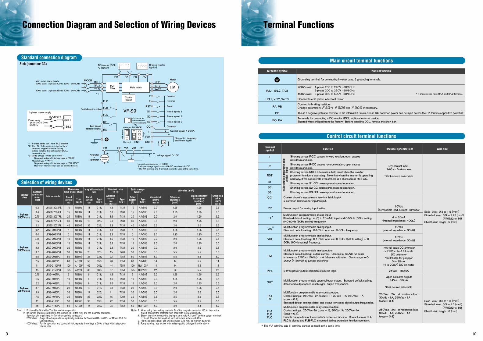
Note) 1. Produced by Schneider Toshiba electric corporation.2. Be sure to attach surge killer to the exciting coil of the relay and the magnetic contactor.
Selection of surge killers for Toshiba magnetic contactors200V class: Surge absorbing units are optionally available for Toshiba C11J to C65J, or Model SS-2 for
C50J and C65J400V class: For the operation and control circuit, regulate the voltage at 200V or less with a step-down
transformer.
Note) 3. When using the auxiliary contacts 2a of the magnetic contactor MC for the control circuit, connect the contacts 2a in parallel to increase reliability.
4. Size of the wires conected to the input terminals R, S and T and the output terminals U, V and W when the length of each wire does not exceed 30m.
5. For the control circuit, use shielded wires 0.75 mm2 or more in diameter.6. For grounding, use a cable with a size equal to or larger than the above.
0.2
0.4
0.75
1.5
2.2
0.2
0.4
0.75
1.5
2.2
3.7
5.5
7.5
11
15
0.75
1.5
2.2
3.7
5.5
7.5
11
15
VFS9S-2002PL
VFS9S-2004PL
VFS9S-2007PL
VFS9S-2015PL
VFS9S-2022PL
VFS9-2002PM
VFS9-2004PM
VFS9-2007PM
VFS9-2015PM
VFS9-2022PM
VFS9-2037PM
VFS9-2055PL
VFS9-2075PL
VFS9-2110PM
VFS9-2150PM
VFS9-4007PL
VFS9-4015PL
VFS9-4022PL
VFS9-4037PL
VFS9-4055PL
VFS9-4075PL
VFS9-4110PL
VFS9-4150PL
1-phase200V class
3-phase200V class
3-phase400V class
Voltageclass Interver model Rated
current(A)
TypeNote 1)
TypeNote 1)
TypeNote 1)
TypeNote 1)
Ratedcurrent
(A)
Adjusted current
(A)(For reference)
Ratedcurrent
(A)
Main circuit(mm2)Note 4)
DC reactor(optional)
(mm2)
Braking resistor/Braking unit(optional)
(mm2)
Groundingcable(mm2)Note 6)
Molded-casecircuit breaker (MCCB)
Magnetic contactor(MC)
Earth leakagebreaker Wire size (mm2)Overload relay
(Th-Ry)Capacityapplicable
motor(kW)
10
15
20
30
40
5
5
10
15
20
30
50
60
100
125
5
10
15
20
30
30
50
60
NJ30N
NJ30N
NJ30N
NJ30N
NJ50E
NJ30N
NJ30N
NJ30N
NJ30N
NJ30N
NJ30N
NJ50E
NJ100F
NJ100F
NJ225F
NJ30N
NJ30N
NJ30N
NJ30N
NJ30N
NJ30N
NJ50E
NJ100F
11
11
11
18
35
11
11
11
11
13
26
35
50
65
80
9
9
9
13
17
25
33
48
C11J
C11J
C11J
C20J
C35J
C11J
C11J
C11J
C11J
C13J
C25J
C35J
C50J
C65J
C80J
C11J
C11J
C11J
C13J
C20J
C25J
C35J
C50J
10
15
20
30
40
5
5
10
15
20
30
50
60
100
125
5
10
15
20
30
30
50
60
NJV50E
NJV50E
NJV50E
NJV50E
NJV50E
NJV50E
NJV50E
NJV50E
NJV50E
NJV50E
NJV50E
NJV50E
NJV60F
NJV100F
NJV225F
NJV50E
NJV50E
NJV50E
NJV50E
NJV50E
NJV50E
NJV50E
NJV100F
2.0
2.0
2.0
3.5
5.5
2.0
2.0
2.0
2.0
2.0
3.5
8.0
14
14
22
2.0
2.0
2.0
2.0
3.5
3.5
5.5
8.0
1.25
1.25
2.0
2.0
2.0
1.25
1.25
2.0
2.0
2.0
5.5
5.5
14
14
22
1.25
1.25
2.0
2.0
2.0
3.5
5.5
8.0
1.25
1.25
1.25
1.25
2.0
1.25
1.25
1.25
1.25
2.0
5.5
5.5
5.5
5.5
5.5
1.25
1.25
1.25
1.25
2.0
2.0
3.5
3.5
3.5
3.5
3.5
3.5
5.5
3.5
3.5
3.5
3.5
3.5
3.5
8.0
14
14
22
3.5
3.5
3.5
3.5
3.5
3.5
5.5
8.0
1.3
2.3
3.6
6.8
9.3
1.3
2.3
3.6
6.8
9.3
15
22
28
44
57
1.6
3.6
5.0
6.8
11
15
22
28
T13J
T13J
T13J
T13J
T13J
T13J
T13J
T13J
T13J
T13J
T20J
T35J
T35J
T65J
T65J
T13J
T13J
T13J
T13J
T13J
T20J
T35J
T35J
Grounding terminal for connecting inverter case. 2 grounding terminals.
Connect to a (3-phase induction) motor.
200V class: 1-phase 200 to 240V - 50/60Hz3-phase 200 to 230V - 50/60Hz
400V class: 3-phase 380 to 500V - 50/60Hz
Connect to braking resistors.Change parameters , and if necessary.
This is a negative potential terminal in the internal DC main circuit. DC common power can be input across the PA terminals (positive potential).
Terminals for connecting a DC reactor (DCL: optional external device).Shorted when shipped from the factory. Before installing DCL, remove the short bar.
R/L1, S/L2, T/L3
U/T1, V/T2, W/T3
PA, PB
PC
PO, PA
Shorting across F-CC causes forward rotation; open causes slowdown and stop.
Shorting across R-CC causes reverce rotation; open causes slowdown and stop. Shorting across RST-CC causes a held reset when the inverter protector function is operating. Note that when the inverter is operating normally, it will not operate even if there is a short across RST-CC.
Control circuit’s equipotential terminal (sink logic).2 common terminals for input/output.
Power output for analog input setting.
24Vdc power output/common at source logic.
Multifunction programmable analog input. Standard default setting: 4 (0) to 20mAdc input and 0-50Hz (50Hz setting) or 0-60Hz (60Hz setting) frequency.
Multifunction programmable analog input. Standard default setting: 0-10Vdc input and 0-80Hz frequency.
Multifunction programmable analog input. Standard default setting: 0-10Vdc input and 0-50Hz (50Hz setting) or 0-60Hz (60Hz setting) frequency.
Multifunction programmable analog output. Standard default setting: output current. Connect a 1mAdc full-scale ammeter or 7.5Vdc (10Vdc)-1mA full-scale voltmeter. Can change to 0-20mA (4-20mA) by jumper switching.
Multifunction programmable open collector output. Standard default settings detect and output speed reach signal output frequencies.
Multifunction programmable relay contact output.Contact ratings: 250Vac - 2A (cosø = 1), 30Vdc - 1A, 250Vac - 1A(cosø = 0.4).Standard default settings detect and output low-speed signal output frequencies.
Multifunction programmable relay contact output.Contact ratings: 250Vac-2A (cosø = 1), 30Vdc-1A, 250Vac-1A(cosø = 0.4).Detects the opertion of the inverter’s protection function. Contact across FLA-FLC is closed and FLB-FLC is opened during protection function operation.
Shorting across S1-CC causes preset speed operation.
Shorting across S2-CC causes preset speed operation.
Shorting across S3-CC causes preset speed operation.
F
R
RST
S1
S2
S3
CC
PP
I I
VIA
VIB
FM
P24
OUT
RCRY
FLAFLBFLC
Dry contact input 24Vdc - 5mA or less
* Sink/source switchable
10Vdc(permissible load current: 10mAdc)
4 to 20mA(internal impedance: 400Ω)
10Vdc(internal impedance: 30kΩ)
10Vdc(internal impedance: 30kΩ)
1mA full-scale DC ammeter or 7.5Vdc 1mA full-scale
DC voltmeter*Switchable for jumpper
0 to 20mA (4 to 20mA) DC ammeter
24Vdc - 100mA
Open collector output:24Vdc - 50mA
*Sink-source selectable
250Vac - 2A: at resistance load30Vdc - 1A, 250Vac - 1A(cosø = 0.4)
Solid wire : 0.3 to 1.5 (mm2)Stranded wire : 0.3 to 1.25 (mm2)
(AWG22 to 16)Sheath strip length : 5 (mm)
Solid wire : 0.3 to 1.5 (mm2)Stranded wire : 0.3 to 1.5 (mm2)
(AWG22 to 16)Sheath strip length : 6 (mm)250Vac - 2A: at resistance load
30Vdc - 1A, 250Vac - 1A(cosø = 0.4)
Standard connection diagram
Selection of wiring devices
* 1-phase series have R/L1 and S/L2 terminal.
Terminals symbol Terminal function
Terminalsymbol Function Electrical specifications Wire size
Sink (common: CC)
R/L1
S/L2
Main circuit power supply200V class: 3-phase 200 to 230V - 50/60Hz
400V class: 3-phase 380 to 500V - 50/60HzFilterEMI Main circuit
Braking resistor(option)
Motor
Forward
Reverse
Reset
Preset speed 1
Preset speed 2
Preset speed 3
Common
Connector for common serial communications
Voltage SOURCE
Current
FM
met
er
Logi
cSINK
Ammeteror
voltmeterFrequency
meter
Current signal: 4-20mA
Designated frequency attainment signal
Voltage signal: 0-10V
Controlcircuit
*1: 1-phase series don’t have T/L3 terminal*2: The PO PA terminals are shorted by a
bar when shipped from the factory.Before installing the DC reactor (DCL), remove the bar.
*3: Model of type “—WN” and “—AN” : Shipment setting of interface logic is “SINK”. Model of type “—WP” : Shipment setting of interface logic is “SOURCE”. However, interface logic can be switched easily.
External potentiometer (1-10kΩ) (or input voltage signal across VIA-CC terminals: 0-10V)* The VIA terminal and II terminal cannot be used at the same time.
1-phase power supply
Power supply1-phase 200 to 240V - 50/60Hz
DC reactor (DCL)*2 (option)
Fault detection relay
Low-speeddetection signal
MCCB (2P)
Mul
tifun
ctio
n pr
ogra
mm
able
con
tact
inpu
t
The VIA terminal and I I terminal cannot be used at the same time.
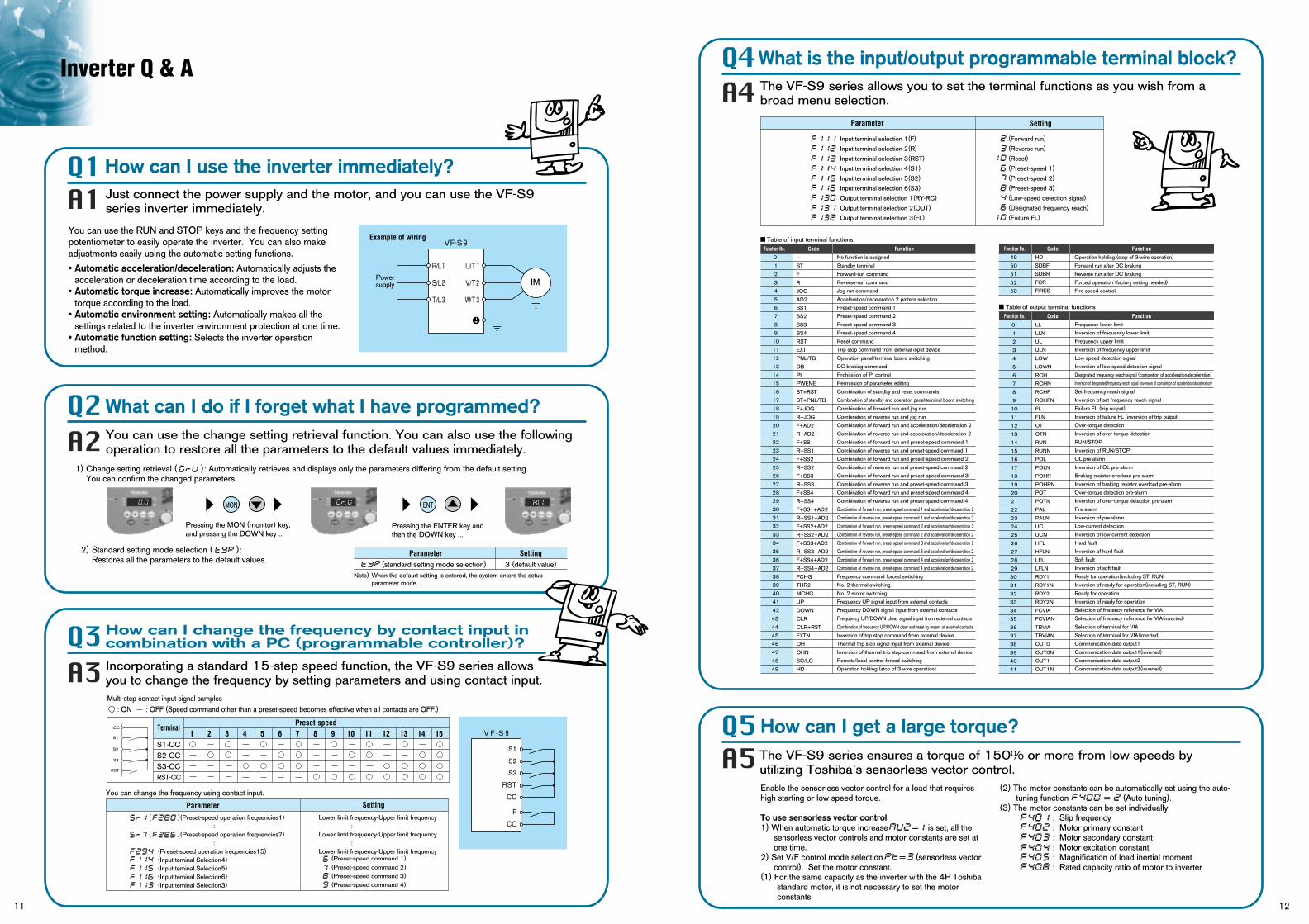
Enable the sensorless vector control for a load that requires high starting or low speed torque.
To use sensorless vector control1) When automatic torque increase = is set, all the
sensorless vector controls and motor constants are set at one time.
2) Set V/F control mode selection = (sensorless vector control). Set the motor constant.
(1) For the same capacity as the inverter with the 4P Toshiba standard motor, it is not necessary to set the motor constants.
(2) The motor constants can be automatically set using the auto-tuning function = (Auto tuning).
(3) The motor constants can be set individually.: Slip frequency: Motor primary constant : Motor secondary constant: Motor excitation constant: Magnification of load inertial moment : Rated capacity ratio of motor to inverter
Inverter Q & A
11 12
How can I use the inverter immediately?
What is the input/output programmable terminal block?
What can I do if I forget what I have programmed?
How can I change the frequency by contact input in combination with a PC (programmable controller)?
Just connect the power supply and the motor, and you can use the VF-S9 series inverter immediately.
The VF-S9 series allows you to set the terminal functions as you wish from a broad menu selection.
Incorporating a standard 15-step speed function, the VF-S9 series allows you to change the frequency by setting parameters and using contact input.
The VF-S9 series ensures a torque of 150% or more from low speeds by utilizing Toshiba’s sensorless vector control.
You can use the RUN and STOP keys and the frequency setting potentiometer to easily operate the inverter. You can also make adjustments easily using the automatic setting functions.
• Automatic acceleration/deceleration: Automatically adjusts the acceleration or deceleration time according to the load.
• Automatic torque increase: Automatically improves the motor torque according to the load.
• Automatic environment setting: Automatically makes all the settings related to the inverter environment protection at one time.
• Automatic function setting: Selects the inverter operation method.
2) Standard setting mode selection ( ): Restores all the parameters to the default values.
You can use the change setting retrieval function. You can also use the following operation to restore all the parameters to the default values immediately.
1) Change setting retrieval ( ): Automatically retrieves and displays only the parameters differing from the default setting. You can confirm the changed parameters.
. .MON ENT
Pressing the ENTER key and then the DOWN key ...
Pressing the MON (monitor) key, and pressing the DOWN key ...
Parameter Setting3 (default value)(standard setting mode selection)
CC
S1
S2
S3
RST
TerminalPreset-speed
S1-CCS2-CCS3-CCRST-CC
1 2 3 4 5 6 7 8 9 10 11 12 13 14 15
You can change the frequency using contact input.
Parameter Setting
( )(Preset-speed operation frequencies1) : ( )(Preset-speed operation frequencies7) : (Preset-speed operation frequencies15) (Input teminal Selection4) (Input teminal Selection5) (Input teminal Selection6) (Input teminal Selection3)
Lower limit frequency-Upper limit frequency :Lower limit frequency-Upper limit frequency :Lower limit frequency-Upper limit frequency
How can I get a large torque?
Input terminal selection 1(F)
Input terminal selection 2(R)
Input terminal selection 3(RST)
Input terminal selection 4(S1)
Input terminal selection 5(S2)
Input terminal selection 6(S3)
Output terminal selection 1(RY-RC)
Output terminal selection 2(OUT)
Output terminal selection 3(FL)
Parameter Setting
(Forward run)
(Reverse run)
(Reset)
(Preset-speed 1)
(Preset-speed 2)
(Preset-speed 3)
(Low-speed detection signal)
(Designated frequency reach)
(Failure FL)
Function No. Code Function0
1
2
3
4
5
6
7
8
9
10
11
12
13
14
15
16
17
18
19
20
21
22
23
24
25
26
27
28
29
30
31
32
33
34
35
36
37
38
39
40
41
42
43
44
45
46
47
48
49
-
ST
F
R
JOG
AD2
SS1
SS2
SS3
SS4
RST
EXT
PNL/TB
DB
PI
PWENE
ST+RST
ST+PNL/TB
F+JOG
R+JOG
F+AD2
R+AD2
F+SS1
R+SS1
F+SS2
R+SS2
F+SS3
R+SS3
F+SS4
R+SS4
F+SS1+AD2
R+SS1+AD2
F+SS2+AD2
R+SS2+AD2
F+SS3+AD2
R+SS3+AD2
F+SS4+AD2
R+SS4+AD2
FCHG
THR2
MCHG
UP
DOWN
CLR
CLR+RST
EXTN
OH
OHN
SC/LC
HD
No function is assigned
Standby terminal
Forward-run command
Reverse-run command
Jog run command
Acceleration/deceleration 2 pattern selection
Preset-speed command 1
Preset-speed command 2
Preset-speed command 3
Preset-speed command 4
Reset command
Trip stop command from external input device
Operation panel/terminal board switching
DC braking command
Prohibition of PI control
Permission of parameter editing
Combination of standby and reset commands
Combination of standby and operation panel/terminal board switching
Combination of forward run and jog run
Combination of reverse run and jog run
Combination of forward run and acceleration/deceleration 2
Combination of reverse run and acceleration/deceleration 2
Combination of forward run and preset-speed command 1
Combination of reverse run and preset-speed command 1
Combination of forward run and preset-speed command 2
Combination of reverse run and preset-speed command 2
Combination of forward run and preset-speed command 3
Combination of reverse run and preset-speed command 3
Combination of forward run and preset-speed command 4
Combination of reverse run and preset-speed command 4
Combination of forward run, preset-speed command 1 and acceleration/deceleration 2
Combination of reverse run, preset-speed command 1 and acceleration/deceleration 2
Combination of forward run, preset-speed command 2 and acceleration/deceleration 2
Combination of reverse run, preset-speed command 2 and acceleration/deceleration 2
Combination of forward run, preset-speed command 3 and acceleration/deceleration 2
Combination of reverse run, preset-speed command 3 and acceleration/deceleration 2
Combination of forward run, preset-speed command 4 and acceleration/deceleration 2
Combination of reverse run, preset-speed command 4 and acceleration/deceleration 2
Frequency command forced switching
No. 2 thermal switching
No. 2 motor switching
Frequency UP signal input from external contacts
Frequency DOWN signal input from external contacts
Frequency UP/DOWN clear signal input from external contacts
Combination of frequency UP/DOWN clear and reset by means of external contacts
Inversion of trip stop command from external device
Thermal trip stop signal input from external device
Inversion of thermal trip stop command from external device
Remote/local control forced switching
Operation holding (stop of 3-wire operation)
Function No. Code Function49
50
51
52
53
HD
SDBF
SDBR
FCR
FIRES
Operation holding (stop of 3-wire operation)
Forward run after DC braking
Reverse run after DC braking
Forced operation (factory setting needed)
Fire speed control
Function No. Code Function
0
1
2
3
4
5
6
7
8
9
10
11
12
13
14
15
16
17
18
19
20
21
22
23
24
25
26
27
28
29
30
31
32
33
34
35
36
37
38
39
40
41
LL
LLN
UL
ULN
LOW
LOWN
RCH
RCHN
RCHF
RCHFN
FL
FLN
OT
OTN
RUN
RUNN
POL
POLN
POHR
POHRN
POT
POTN
PAL
PALN
UC
UCN
HFL
HFLN
LFL
LFLN
RDY1
RDY1N
RDY2
RDY2N
FCVIA
FCVIAN
TBVIA
TBVIAN
OUT0
OUT0N
OUT1
OUT1N
Frequency lower limit
Inversion of frequency lower limit
Frequency upper limit
Inversion of frequency upper limit
Low-speed detection signal
Inversion of low-speed detection signal
Designated frequency reach signal (completion of acceleration/deceleration)
Inversion of designated frequency reach signal (inversion of completion of acceleration/deceleration)
Set frequency reach signal
Inversion of set frequency reach signal
Failure FL (trip output)
Inversion of failure FL (inversion of trip output)
Over-torque detection
Inversion of over-torque detection
RUN/STOP
Inversion of RUN/STOP
OL pre-alarm
Inversion of OL pre-alarm
Braking resistor overload pre-alarm
Inversion of braking resistor overload pre-alarm
Over-torque detection pre-alarm
Inversion of over-torque detection pre-alarm
Pre-alarm
Inversion of pre-alarm
Low-current detection
Inversion of low-current detection
Hard fault
Inversion of hard fault
Soft fault
Inversion of soft fault
Ready for operation(including ST, RUN)
Inversion of ready for operation(including ST, RUN)
Ready for operation
Inversion of ready for operation
Selection of freqency reference for VIA
Selection of freqency reference for VIA(inverted)
Selection of terminal for VIA
Selection of terminal for VIA(inverted)
Communication data output1
Communication data output1(inverted)
Communication data output2
Communication data output2(inverted)
Table of output terminal functions
Table of input terminal functions VF-S9
R/L1 U/T1
S/L2 V/T2Power supply IM
T/L3 W/T3
Example of wiring
VF-S9
F
RST
CC
S3
S2
S1
CC
(Preset-speed command 1)(Preset-speed command 2)(Preset-speed command 3)(Preset-speed command 4)
Note) When the defaurt setting is entered, the system enters the setup parameter mode.
Multi-step contact input signal samples : ON : OFF (Speed command other than a preset-speed becomes effective when all contacts are OFF.)
Inverter Q & A
13 14
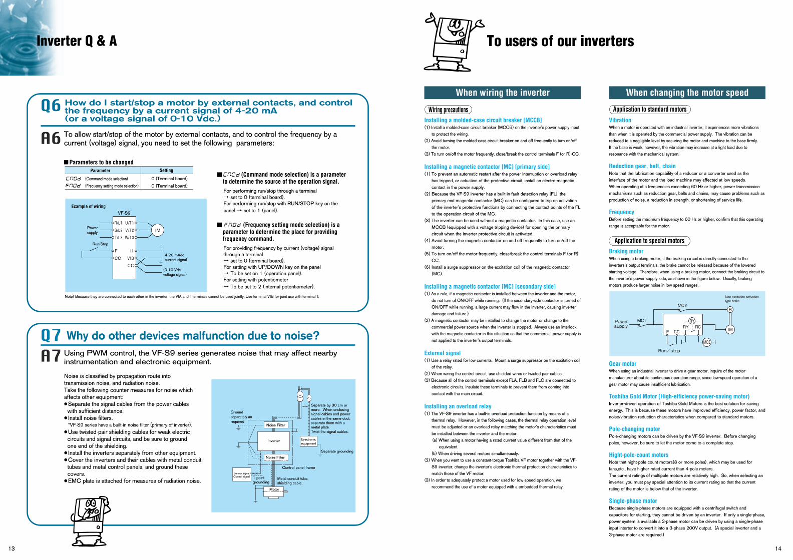
How do I start/stop a motor by external contacts, and control the frequency by a current signal of 4-20 mA (or a voltage signal of 0-10 Vdc.)
To allow start/stop of the motor by external contacts, and to control the frequency by a current (voltage) signal, you need to set the following parameters:
Parameters to be changedParameter Setting
(Command mode selection)
(Frecuency setting mode selection)
0 (Terminal board)
0 (Terminal board)
(Command mode selection) is a parameter to determine the source of the operation signal.
For performing run/stop through a terminal → set to 0 (terminal board).For performing run/stop with RUN/STOP key on thepanel → set to 1 (panel).
(Frequency setting mode selection) is a parameter to determine the place for providing frequency command.
For providing frequency by current (voltage) signal through a terminal→ set to 0 (terminal board).For setting with UP/DOWN key on the panel → To be set on 1 (operation panel).For setting with potentiometer→ To be set to 2 (internal potentiometer).
VF-S9
R/L1 U/T1
S/L2 V/T2
F II
CC VIB
CC(0-10 Vdcvoltage signal)
4-20 mAdccurrent signal
Power supply
Run/Stop
IM
T/L3 W/T3
Example of wiring
Why do other devices malfunction due to noise? Using PWM control, the VF-S9 series generates noise that may affect nearbyinstrumentation and electronic equipment.
Noise is classified by propagation route into transmission noise, and radiation noise. Take the following counter measures for noise which affects other equipment: Separate the signal cables from the power cables with sufficient distance. Install noise filters. *VF-S9 series have a built-in noise filter (primary of inverter). Use twisted-pair shielding cables for weak electric circuits and signal circuits, and be sure to ground one end of the shielding. Install the inverters separately from other equipment. Cover the inverters and their cables with metal conduit
tubes and metal control panels, and ground these covers.
EMC plate is attached for measures of radiation noise.
Separate grounding
Erectronicequipment
Control panel frame
Metal conduit tube,shielding cable,
1 pointgrounding
Sensor signalControl signal
Noise Filter
Inverter
Groundseparately asrequired
Separate by 30 cm ormore. When enclosing signal cables and powercables in the same duct,separate them with ametal plate.Twist the signal cables.
Motor
Noise Filter
+
+
Note) Because they are connected to each other in the inverter, the VIA and ll terminals cannot be used jointly. Use terminal VIB for joint use with terminal ll.
To users of our inverters
Wiring precautionsInstalling a molded-case circuit breaker [MCCB] (1) Install a molded-case circuit breaker (MCCB) on the inverter's power supply input
to protect the wiring.(2) Avoid turning the molded-case circuit breaker on and off frequently to turn on/off
the motor.(3) To turn on/off the motor frequently, close/break the control terminals F (or R)-CC.
Installing a magnetic contactor [MC] [primary side] (1) To prevent an automatic restart after the power interruption or overload relay
has tripped, or actuation of the protective circuit, install an electro-magnetic contact in the power supply.
(2) Because the VF-S9 inverter has a built-in fault detection relay [FL], the primary end magnetic contactor (MC) can be configured to trip on activation of the inverter's protective functions by connecting the contact points of the FL to the operation circuit of the MC.
(3) The inverter can be used without a magnetic contactor. In this case, use an MCCB (equipped with a voltage tripping device) for opening the primary circuit when the inverter protective circuit is activated.
(4) Avoid turning the magnetic contactor on and off frequently to turn on/off the motor.
(5) To turn on/off the motor frequently, close/break the control terminals F (or R)-CC.
(6) Install a surge suppressor on the excitation coil of the magnetic contactor (MC).
Installing a magnetic contactor [MC] [secondary side](1) As a rule, if a magnetic contactor is installed between the inverter and the motor,
do not turn of ON/OFF while running. (If the secondary-side contactor is turned of ON/OFF while running, a large current may flow in the inverter, causing inverter damage and failure.)
(2) A magnetic contactor may be installed to change the motor or change to the commercial power source when the inverter is stopped. Always use an interlock with the magnetic contactor in this situation so that the commercial power supply is not applied to the inverter's output terminals.
External signal (1) Use a relay rated for low currents. Mount a surge suppressor on the excitation coil
of the relay.(2) When wiring the control circuit, use shielded wires or twisted pair cables.(3) Because all of the control terminals except FLA, FLB and FLC are connected to
electronic circuits, insulate these terminals to prevent them from coming into contact with the main circuit.
Installing an overload relay (1) The VF-S9 inverter has a built-in overload protection function by means of a
thermal relay. However, in the following cases, the thermal relay operation level must be adjusted or an overload relay matching the motor's characteristics must be installed between the inverter and the motor.(a) When using a motor having a rated current value different from that of the
equivalent. (b) When driving several motors simultaneously.
(2) When you want to use a constant-torque Toshiba VF motor together with the VF-S9 inverter, change the inverter's electronic thermal protection characteristics to match those of the VF motor.
(3) In order to adequately protect a motor used for low-speed operation, we recommend the use of a motor equipped with a embedded thermal relay.
When wiring the inverter
Application to standard motors
Application to special motors
VibrationWhen a motor is operated with an industrial inverter, it experiences more vibrations than when it is operated by the commercial power supply. The vibration can be reduced to a negligible level by securing the motor and machine to the base firmly.If the base is weak, however, the vibration may increase at a light load due to resonance with the mechanical system.
Reduction gear, belt, chain Note that the lubrication capability of a reducer or a converter used as the interface of the motor and the load machine may affected at low speeds.When operating at a frequencies exceeding 60 Hz or higher, power transmission mechanisms such as reduction gear, belts and chains, may cause problems such as production of noise, a reduction in strength, or shortening of service life.
FrequencyBefore setting the maximum frequency to 60 Hz or higher, confirm that this operating range is acceptable for the motor.
Braking motor When using a braking motor, if the braking circuit is directly connected to the inverters's output terminals, the brake cannot be released because of the lowered starting voltage. Therefore, when using a braking motor, connect the braking circuit to the inverter's power supply side, as shown in the figure below. Usually, braking motors produce larger noise in low speed ranges.
Gear motor When using an industrial inverter to drive a gear motor, inquire of the motor manufacturer about its continuous operation range, since low-speed operation of a gear motor may cause insufficient lubrication.
Toshiba Gold Motor (High-efficiency power-saving motor)Inverter-driven operation of Toshiba Gold Motors is the best solution for saving energy. This is because these motors have improved efficiency, power factor, and noise/vibration reduction characteristics when compared to standard motors.
Pole-changing motorPole-changing motors can be driven by the VF-S9 inverter. Before changing poles, however, be sure to let the motor come to a complete stop.
Hight-pole-count motorsNote that hight-pole count motors(8 or more poles), which may be used for fans,etc., have higher rated current than 4-pole moters.The current ratings of multipole motors are relatively high. So, when selecting an inverter, you must pay special attention to its current rating so that the current rating of the motor is below that of the inverter.
Single-phase motorBecause single-phase motors are equipped with a centrifugal switch and capacitors for starting, they cannot be driven by an inverter. If only a single-phase, power system is availabls a 3-phase motor can be driven by using a single-phase input interter to convert it into a 3-phase 200V output. (A special inverter and a 3-phase motor are required.)
When changing the motor speed
Non-excitation activation type brake
MC1
MC2
F
B
CC RY RC
IM
Power supply
Run/stop
MC2
RY

15 16
Notes
【Measures against effects of leakage current】The measures against the effects of leakage current are as follows:1) Measures to prevent the malfunction of leakage circuit breakers (1) Decrease the PWM carrier frequency of the inverter. In the case of
the VF-S9, the frequency can be decreased to 2.0kHz. (*) (2) Install leakage circuit breakers (ELCB) with a high-frequency
protective function (e.g., Toshiba Mighty series of breakers) in both the same and the other power distribution lines. This makes it possible to operate the VF- S9 with its PWM carrier frequency set high.
2) Measures against malfunction of ground-fault relay: (1) Decrease the PWM carrier frequency of the inverter. In the case of the VF-S9, the frequency can be decreased to 2.0kHz. (*) (2) Install ground-fault relays with a high-frequency protective function
(e.g., Toshiba CCR12 type of relays) in both the same and other lines. This makes it possible to operate the VF-S9 with its PWM carrier frequency set high.
3) Measures against noise produced by other electric and electronic systems: (1) Separate the grounding line of the inverter from that of the affected electric and electronic systems. (2) Decrease the PWM carrier frequency of the inverter. In the case of
the VF-S9, the frequency can be decreased to 2.0kHz. (*)4) Measures against malfunction of external thermal relays: (1) Remove the external thermal relay and use the electronic thermal function of the inverter instead of it. (Unapplicable to cases where a
single inverter is used to drive more than one motor. Refer to the instruction manual for measures to be taken when thermal relays cannot be removed.)
(2) Decrease the PWM carrier frequency of the inverter. In the case of the VF-S9, the frequency can be decreased to 2.0kHz.
Note) If the carrier frequency reduce, the magnetic noise caused by the motor increase.
Leakage currentThe VF-S9 series of inverters uses high-speed switching deuices for PWM control.When a relatively long cable is used for power supply to an inverter, current may leak from the cable or the motor to the ground because of its capacitance, adversely affecting peripheral equipment. The intensity of such a leakage current depends on the PWM carrier frequency, the lengths of the input and output cables, etc., of the inverter. To prevent current leakage, it is recommended to take the following measures.
【Effects of leakage current】Leakage current which increases when an inverter is used may pass through the following routes: Route (1) ... Leakage due to the capacitance between the ground and the noise filter Route (2) ... Leakage due to the capacitance between the ground and the inverter Route (3) ... Leakage due to the capacitance between ground and the cable connecting the inverter and the motor Route (4) ... Leakage due to the capacitance of the cable connecting the motor and an inverter in another power distribution line Route (5) ... Leakage through the grounding line common to motors Route (6) ... Leakage to another line because of the capacitance of the groundLeakage current which passes through the above routes may cause the following trouble. Malfunction of a leakage circuit breaker in the same or another power distribution line Malfunction of a ground-relay installed in the same or another power distribution line Noise produced at the output of an electronic device in another power distribution line Activation of an external thermal relay installed between the inverter and the motor, at a current below the rate current
Ground faultBefore begining operation, thoroughly check the wiring between the motor and the inverter for incorrect wiring or short circuits. Do not ground the neutral point of any star-connected motor.
Radio interference[Noise produced by inverters]Since the VF-S9 series of inverters performs PWM control, it produces noise and sometimes affects nearby instrumental devices, electrical and electronic systems, etc. The effects of noise greatly vary with the noise resistance of each individual device, its wiring condition, the distance between it and the inverter, etc.[Measures against noises]According to the route through which noise is transmitted, the noises produced by an inverter are classified into transmission noise, induction noise and radiation noise.[Examples of protective measures]Separate the power line from other lines, such as weak-current lines and signal lines, and install them apart from each other.Install a noise filter in each inverter. It is effective for noise prevention to install noise filters in other devices and systems, as well.Shield cables and wires with grounded metallic conduits, and cover electronic systems with grounded metallic cases.Separate the power distribution line of the inverter from that of other devices and systems.Install the input and output cables of the inverter apart from each other.Use shielded twisted pair wires for wiring of the weak-current and signal circuits, and always ground one of each pair of wires.Ground the inverter with grounding wires as large and short as possible, separately from other devices and systems.
All models have built-in noise filters which significantly reduce noise.
Power factor improvement capacitors Do not install a power factor improvement capacitors on the input or output side of the inverter.Installing a power factor improvement capacitor on the input or output side causes current containing harmonic components to flow into the capacitor, adversely affecting the capacitor itself or causing the inverter to trip. To improve the power factor, install an input AC reactor or a DC reactor (optional) on the primary side of the inverter.
Exclusive grounding
Electronic system
Control panel enclosure
Metallic conduit, Plica tube, shielded cable, etc
Ground every shielded cable at one point
Sensor signalControl signal
Inverter
Exclusive grounding, if necessary
Install the wires 30 cm or more apart from each other.When the wires are installed in thesame duct, separate the weak-current ine and the strong-current line with a metallic separator.Use twisted wires for weak-current lines.
5) Measures by means of wiring and grounding (1) Use a grounding wire as large as possible. (2) Separate the inverter's grounding wire from that of other systems or install
the grounding wire of each system separately to the grounding point. (3) Ground (shield) the main circuit wires with metallic conduits. (*): The PWM carried frequency should not be decreased below 2.2kHz in the vector control mode.
Power supply ELCB Noise filter
Inverter
Ground-fault relay
motor
① ② ③
④
⑤⑥
M
M
Leakage current flow routes
When studying how to use our inverters
motor
Noise filter
Noise filter
Installation of input AC rectorsThese devices are used to improve the input power factor and suppress high harmonic currents and surges. Install an input AC reactor when using a VF-S9 inverter under the following conditions:(1) When the power source capacity is 200kVA or more, and when it is 10
times or more greater than the inverter capacity.(2) When the inverter is connected the same power distribution system as a
thyristor-committed control equipment.(3) When the inverter is connected to the same power distribution system as that
of distorted wave-producing systems, such as arc furnaces and large-capacity inverters.
Standard replacement intervals of main parts The table below lists standard component replacement intervals under normal operating conditions (i.e., average year round ambient temperature of 30∞C, load ratio of 80% or less, average operation time of 12 hours/day). The replacement intervals do not indicates the service life of each component, but the number of years beyond which the failure rate of a component used without being replaced increases shapely because of deterioration and wear.
Component name
2 to 3 years
5 years
10 years
5 years
Replaced with a new one
Replaced with a new one (upon examination)
Decided upon examination of the cumulative operation time
Replaced with a new one
Replaced with a new circuit board (upon examination)
Decided upon examination
Standard replacement intervals Replacement method, etc.
Cooling fan
Smoothing capacitor
Circuit breaker, relay
Aluminum capacitors on the printed circuit board
Timer
Fuse
Extract from "Periodic Inspection of General-purpose Inverters" published by the Japan Electrical Manufacturers' AssociationNote: The service life of each component greatly varies with its usage environment.
Selecting the capacity (model) of the inverter
SelectionCapacityRefer to the applicable motor capacities listed in the standard specifications.When driving a high-pole motor, special motor, or multiple motors in parallel, select such an inverter that the sum of the motor rated current multiplied by 1.05 to 1.1 is less than the inverter's rated output current value.
Acceleration/deceleration timesThe actual acceleration and deceleration times of a motor driven by an inverter are determined by the torque and moment of inertia2 of the load, and can be calculated by the following equations.The acceleration and deceleration times of an inverter can be set individually. In any case, however, they should be set longer than their respective values determined by the following equations.
Allowable torque characteristicsWhen a standard motor is combined with an inverter to perform variable speed operation, the motor temperature rises slightly higher than it normally does during commercial power supply operation. This is because the inverter output voltage has a sinusoidal (approximate) PWM waveform. In addition, the cooling becomes less effective at low speed, so the torque must be reduced according to the frequency.When constant-torque operation must be performed at low speeds, use a Toshiba VF motor designed specifically for use with inverters.
Starting characteristicsWhen a motor is driven by an inverter, its operation is restricted by the inverter’s overload current rating, so the starting characteristic is different from those obtained from commercial power supply operation.Although the starting torque is smaller with an inverter than with the commercial power supply, a high starting torque can be produced at low speeds by adjusting the V/f pattern torque boost amount or by employing vector control. (200% in sensorless control mode, though this rate varies with the motor characteristics.) When a larger starting torque is necessary, select an inverter with a larger capacity and examine the possibility of increasing the motor capacity.
Acceleration time
Deceleration time
Conditions
ta =(JM+JL)×N
9.56×(TM-TL)(sec.)
ta =(JM+JL)×N
9.56×(TB+TL)(sec.)
JM
JL
N
TL
TM
TB
: Moment of inertia of motor (kge.m2): Moment of inertia of load (kge.m2) (converted into value on motor shaft): Difference in rotating speed between before and after acc. or dce. (min.-1): Load torque (Ne.m): Motor rated torque x 1.2-1.3 (Ne.m) ... V/f control: Motor rated torque x 1.5 (Ne.m) ... Vector operation control: Motor rated torque x 0.2 (Ne.m)
When a braking resistor or a braking resistor unit is used:Motor rated torque x 0.8-1.0 (Ne.m)( )
To users of our inverters
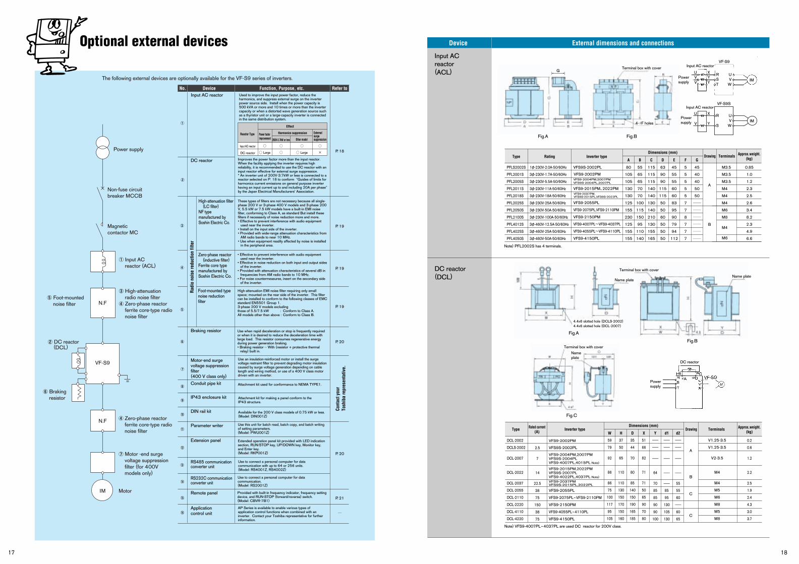
Optional external devices
17 18
Input AC reactor(ACL)
DC reactor(DCL)
Device External dimensions and connections
①
②
③
④
⑤
⑥
⑦
⑧
⑨
⑩
⑪
⑫
⑬
⑭
⑮
⑯
Input AC reactor
DC reactor
High-attenuation filter (LC filter)NF type manufactured by Soshin Electric Co.
Braking resistor
Conduit pipe kit
Motor-end surge voltage suppression filter (400 V class only)
Zero-phase reactor (inductive filter)Ferrite core type manufactured by Soshin Electric Co.
Foot-mounted type noise reduction filter
P. 18
P. 19
P. 19
P. 19
P. 20
P. 20
P. 21
Used to improve the input power factor, reduce the harmonics, and suppress external surge on the inverter power source side. Install when the power capacity is 500 kVA or more and 10 times or more than the inverter capacity or when a distorted wave generation source such as a thyristor unit or a large-capacity inverter is connected in the same distribution system.
Improves the power factor more than the input reactor. When the facility applying the inverter requires high reliability, it is recommended to use the DC reactor with an input reactor effective for external surge suppression. * An inverter unit of 200V-3.7kW or less is connected to a reactor selected on P. 18 to conform “Guides of limits for harmonics current emissions on general purpose inverter having an input current up to and including 20A per phase” by the Japan Electrical Manufacturers' Association.
These types of filters are not necessary because all single-phase 200 V or 3-phase 400 V models and 3-phase 200 V, 5.5 kW or 7.5 kW models have a built-in EMI noise filter, conforming to Class A, as standard But install these filters if necessavly of noise reduction more and more.• Effective to prevent interference with audio equipment
used near the inverter.• Install on the input side of the inverter.• Provided with wide-range attenuation characteristics from
AM radio bands to near 10 MHz.• Use when equipment readily affected by noise is installed
in the peripheral area.
IP43 enclosure kit
DIN rail kit
Parameter writer
Extension panel
RS485 communication converter unit
RS232C communication converter unit
Remote panel
Application control unit
High-attenuation EMI noise filter requiring only small space; mounted on the rear side of the inverter. This filter can be installed to conform to the following classes of EMC standard EN5501 Group 1.3-phase 200 V models excluding those of 5.5/7.5 kW : Conform to Class A.All models other than above : Conform to Class B.
• Effective to prevent interference with audio equipment used near the inverter.
• Effective in noise reduction on both input and output sides of the inverter.
• Provided with attenuation characteristics of several dB in frequencies from AM radio bands to 10 MHz.
• For noise countermeasures, insert on the secondary side of the inverter.
Use when rapid deceleration or stop is frequently required or when it is desired to reduce the deceleration time with large load. This resistor consumes regenerative energy during power generation braking.• Braking resistor -- With (resistor + protective thermal
relay) built in.
Use this unit for batch read, batch copy, and batch writing of setting parameters. (Model: PWU001Z)
Attachment kit used for conformance to NEMA TYPE1.
Use an insulation-reinforced motor or install the surge voltage restraint filter to prevent degrading motor insulation caused by surge voltage generation depending on cable length and wiring method, or use of a 400 V class motor driven with an inverter.
Extended operation panel kit provided with LED indication section, RUN/STOP key, UP/DOWN key, Monitor key, and Enter key.(Model: RKP001Z)
Use to connect a personal computer for data communication with up to 64 or 256 units. (Model: RS4001Z, RS4002Z)
Use to connect a personal computer for data communication. (Model: RS2001Z)
Provided with built-in frequency indicator, frequency setting device, and RUN-STOP (forward/reverse) switch. (Model: CBVR-7B1)
AP Series is available to enable various types of application control functions when combined with an inverter. Contact your Toshiba representative for further information.
Radi
o no
ise
redu
ctio
n fil
ter
Reactor Type
Input AC reactor
DC reactor
Large
Large
×
Power factor improvement
Harmonics suppression
Effect
External surge suppression200V-3.7kW or less Other model
Attachment kit for making a panel conform to the IP43 structure.
Available for the 200 V class models of 0.75 kW or less. (Model: DIN001Z)
① Input AC reactor (ACL)
Non-fuse circuit breaker MCCB
Power supply
The following external devices are optionally available for the VF-S9 series of inverters.
Magnetic contactor MC
③ High-attenuation radio noise filter
④ Zero-phase reactor ferrite core-type radio noise filter
② DC reactor (DCL)
N.F
N.F
VF-S9
④ Zero-phase reactor ferrite core-type radio noise filter
IM
⑤ Foot-mounted noise filter
⑥ Braking resistor
⑦ Motor -end surge voltage suppression filter (for 400V models only)
Motor
RatingType Inverter type Drawing Terminals Approx.weight.(kg)
Dimensions (mm)
A B C D E F G
PFLS2002S
PFL2001S
PFL2005S
PFL2011S
PFL2018S
PFL2025S
PFL2050S
PFL2100S
PFL4012S
PFL4025S
PFL4050S
1φ-230V-2.0A-50/60Hz
3φ-230V-1.7A-50/60Hz
3φ-230V-5.5A-50/60Hz
3φ-230V-11A-50/60Hz
3φ-230V-18A-50/60Hz
3φ-230V-25A-50/60Hz
3φ-230V-50A-50/60Hz
3φ-230V-100A-50/60Hz
3φ-460V-12.5A-50/60Hz
3φ-460V-25A-50/60Hz
3φ-460V-50A-50/60Hz
VFS9S-2002PL 80
105
105
130
130
125
155
230
125
155
155
55
65
65
70
70
100
115
150
95
110
140
115
115
115
140
140
130
140
210
130
155
165
63
90
90
115
115
50
50
60
50
50
50
45
55
55
60
60
83
95
90
79
94
112
A
B
5
5
5
5
5
7
7
8
7
7
7
45
40
40
50
50
――
――
――
――
――
――
0.85
1.0
1.2
2.3
2.5
2.6
3.4
8.2
2.3
4.9
6.6
M3.5
M3.5
M3.5
M4
M4
M4
M6
M8
M4
M6
VFS9-2055PL
VFS9-2075PL,VFS9-2110PM
VFS9-2150PM
VFS9-4007PL~VFS9-4037PL
VFS9-4055PL~VFS9-4110PL
VFS9-4150PL
VFS9-2004PM,2007PMVFS9S-2004PL,2007PL
VFS9-2015PM、2022PM
Note) PFL2002S has 4 terminals.
Rated current(A) Inverter typeType Drawing Terminals Approx.weight.
(kg)Dimensions (mm)
W H D X Y d1 d2
DCL-2002
DCLS-2002
DCL-2007
DCL-2022
DCL-2037
DCL-2055
DCL-2110
DCL-2220
DCL-4110
DCL-4220
2.5
7
14
22.5
38
75
150
38
75
VFS9-2002PM
VFS9S-2002PL
VFS9-2055PL
VFS9-2075PL~VFS9-2110PM
VFS9-2150PM
VFS9-4055PL~4110PL
VFS9-4150PL
59
79
92
86
86
75
100
117
95
105
37
50
65
110
110
130
150
170
150
160
35
44
70
80
85
140
150
190
165
185
51
66
82
71
71
50
65
90
70
80
A
B
C
C
-
-
-
64
70
85
85
90
90
100
-
-
-
-
-
85
95
130
105
130
-
-
-
-
55
55
60
-
60
65
0.2
0.6
1.2
2.2
2.5
1.9
2.4
4.3
3.0
3.7
Note) VFS9-4007PL~4037PL are used DC reactor for 200V class.
VFS9-2004PM,2007PMVFS9S-2004PLVFS9-4007PL,4015PL Note)
VFS9-2015PM,2022PMVFS9S-2007PLVFS9-4022PL,4037PL Note)
VFS9-2037PMVFS9S-2015PL,2022PL
V1.25-3.5
V1.25-3.5
V2-3.5
M4
M4
M5
M6
M8
M5
M8
VF-S9S
VF-S9
Input AC reactor
R
G
X
Y
U
VPowersupply
UV IM
S W
Input AC reactor
RX
Y
U
VYVPower
supply
UV IM
TS
W
Fig.A
図A
Fig.B
Fig.C
VFS9-2037PM,VFS9S-2015PL,VFS9S-2022PL
VFS9-2002PM
No. Device Function, Purpose, etc. Refer to
Cont
act y
our
Tosh
iba
repr
esen
tativ
e.
Terminal box with cover
4- F holes
4.4x6 slotted hole (DCLS-2002)4.4x6 slotted hole (DCL-2007)
Terminal box with coverNameplate
Name plateName plate
Terminal box with cover
Fig.B
Fig.A
DC reactor
Powersupply
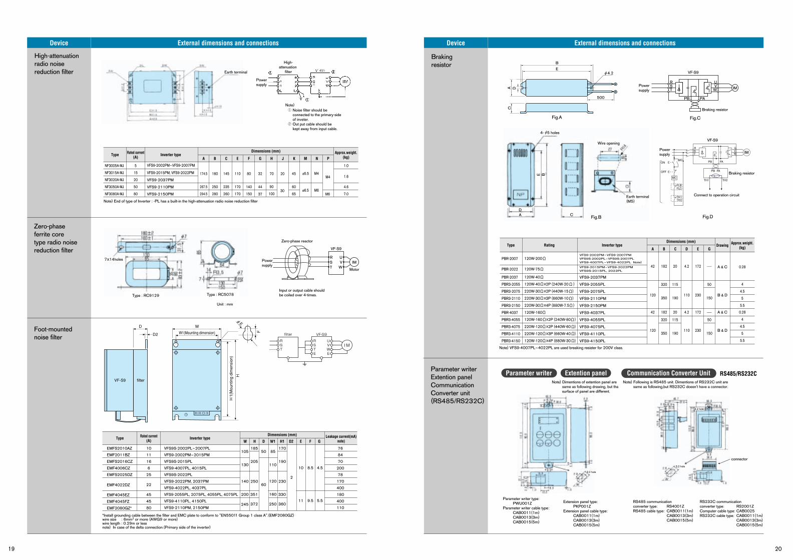
19 20
Brakingresistor
Parameter writerExtention panelCommunicationConverter unit(RS485/RS232C)
Device External dimensions and connections
High-attenuationradio noisereduction filter
Zero-phaseferrite coretype radio noisereduction filter
Foot-mountednoise filter
Device External dimensions and connections
Extention panelParameter writer Communication Converter Unit RS485/RS232C
Rated current(A) Inverter typeType Approx.weight.
(kg)Dimensions (mm)
A B C E F G H J K M N P
NF3005A-MJ
NF3015A-MJ
NF3020A-MJ
NF3050A-MJ
NF3080A-MJ
5
15
20
50
80
VFS9-2037PM
VFS9-2110PM
VFS9-2150PM
174.5 160 145 110 80 32
267.5
294.5
250
280
235
260
170
170
140
150
45
60
65
M4M4
M644
37
70 20
30
ø5.5
ø6.5M6
90
100
1.0
1.6
4.6
7.0
VFS9-2002PM~VFS9-2007PM
VFS9-2015PM, VFS9-2022PM
Note) End of type of Inverter : -PL has a built-in the high-attenuation radio noise reduction filter
Type Inverter type Leakage current(mA)note)
Rated current(A)
EMFS2010AZ
EMF2011BZ
EMFS2016CZ
EMF4006CZ
EMFS2025DZ
VFS9S-2002PL~2007PL
VFS9-2002PM~2015PM
VFS9S-2015PL
VFS9-4007PL, 4015PL
VFS9S-2022PL
VFS9-2022PM, 2037PM
VFS9-4022PL, 4037PL
VFS9-2055PL, 2075PL, 4055PL, 4075PL
VFS9-4110PL, 4150PL
VFS9-2110PM, 2150PM
76
84
70
200
78
170
400
180
400
110
105
130
140
185
205
250
50 85
110
120
160
250
60
2
10 8.5 4.5
11 9.5 5.5
200
245
351
372
170
190
230
330
360
10
11
16
6
25
45
45
80
22
EMF4045EZ
EMF4045FZ
EMF2080GZ*
EMF4022DZ
Dimensions (mm)
W H D W1 H1 D2 E F G
VF-S9
Zero-phase reactor
RS
UV
Unit : mm
IM
Motor
Input or output cable shouldbe coiled over 4-times.
T W
RatingType Inverter type Drawing Approx.weight.(kg)
Dimensions (mm)
A B C D E G
PBR-2007
PBR-2022
PBR-2037
PBR3-2055
PBR3-2075
PBR3-2110
PBR3-2150
PBR-4037
PBR3-4055
PBR3-4075
PBR3-4110
PBR3-4150
120W-200
120W-75
120W-40
120W-40 X2P (240W-20 )
220W-30 X2P (440W-15 )
220W-30 X3P (660W-10 )
220W-30 X4P (880W-7.5 )
120W-160
120W-160 X2P (240W-80 )
220W-120 X2P (440W-60 )
220W-120 X3P (660W-40 )
120W-120 X4P (880W-30 )
42
120
42
120
110
4.2
110
182
320
350
320
350
182
20
115
190
115
190
20
-
50
150
50
150
-
4.2
230
172
230
172 A & C
B & D
A & C
B & D
0.28
4
4.5
5
5.5
0.28
4
4.5
5
5.5
VFS9-2037PM
VFS9-2055PL
VFS9-2075PL
VFS9-2110PM
VFS9-2150PM
VFS9-4037PL
VFS9-4055PL
VFS9-4075PL
VFS9-4110PL
VFS9-4150PL
VFS9-2002PM~VFS9-2007PMVFS9S-2002PL~VFS9S-2007PLVFS9-4007PL~VFS9-4022PL Note)
VFS9-2015PM~VFS9-2022PMVFS9S-2015PL, 2022PL
Extension panel type:PKP001Z
Extension panel cable type:CAB0011(1m)CAB0013(3m)CAB0015(5m)
Parameter writer type: PWU001Z
Parameter writer cable type: CAB0011(1m)CAB0013(3m)CAB0015(5m)
RS232C communication converter type: RS2001ZComputer cable type: CAB0025RS232C cable type: CAB0011(1m)
CAB0013(3m)CAB0015(5m)
RS485 communication converter type: RS4001ZRS485 cable type: CAB0011(1m)
CAB0013(3m)CAB0015(5m)
VF-S9
VF-S9
Fig.C
Fig.D
Fig.A
Fig.B
RS
UV IMT
B
C
A
E
D
500 PA
Braking resistor
Powersupply
PB
W
Note) Following is RS485 unit. Dimentions of RS232C unit are same as following,but RS232C doesn't have a connector.
Note) Dimentions of extention panel are same as following drawing, but tha surface of panel are different.
Note) VFS9-4007PL~4022PL are used breaking resister for 200V class.
connector
IMUVW
PA
PA
PB
PB
TH2TH1
Braking resistor
Connect to operation circuit
RST
MC
MC
E
E
ON
OFF
FLBFLC
TH1TH2
Powersupply
Earth terminal
High-attenuation
filter
Note) Noise filter should beconnected to the primary-sideof inveter.Out put cable should bekept away from input cable.
7X14holes
Type : RC9129 Type : RC5078
Power supply
Power supply
4.2
Wire opening
Earth terminal(M5)
4- 5 holes
CDA
BE
3.2 hole3.2 hole
3.2 hole
3.2 hole
PBR-2007 120W-200
PBR-2022 120W-75
I M
VF-S9
UVWE
RSTE
filter
RST
*Install grounding cable between the filter and EMC plate to conform to "EN55011 Group 1 class A".(EMF2080GZ)wire size : 6mm2 or more (AWG9 or more)wire length : 0.29m or lessnote) In case of the delta connection.(Primary side of the inverter)
D
D2
W
W1(Mounting dimension)
H
F
H1(Mounting dimension)
VF-S9 filter
φE
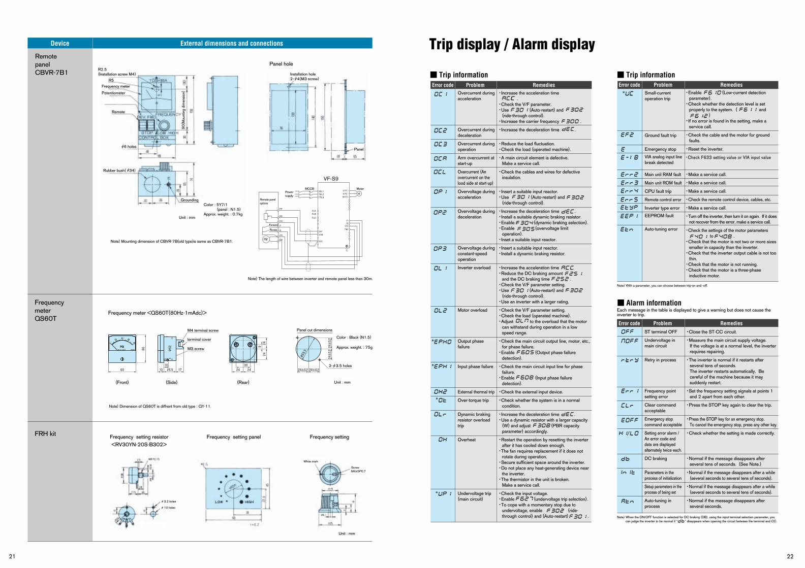
21 22
Frequencymeter QS60T
FRH kit
Trip display / Alarm display
Trip information
Alarm information
Each message in the table is displayed to give a warning but does not cause the inverter to trip.
80
80Hz-1mAdc QS60T
(Rear)(Front)
Hz
20 40 60
0
(Side)
60 24
9 24±0.2
24±0.2
24±0.2 24±0.2
24
60 13
10
25.5 24
30
24 17
Color : Black (N1.5)
Approx. weight. : 75g
Panel cut dimensions
φ53.5
φ52
M4 terminal screw
terminal cover
M3 screw
Note) Dimension of QS60T is diffrent from old type : QY-11.
Frequency meter <QS60T(80Hz-1mAdc)>
Frequency setting resistor<RV30YN-20S-B302>
Frequency setting panel Frequency setting
Panel hole
Trip information
・Close the ST-CC circuit.
・Measure the main circuit supply voltage.If the voltage is at a normal level, the inverter requires repairing.
・The inverter is normal if it restarts after several tens of seconds.The inverter restarts automatically. Be careful of the machine because it may suddenly restart.
・Set the frequency setting signals at points 1 and 2 apart from each other.
・Press the STOP key again to clear the trip.
・Press the STOP key for an emergency stop.To cancel the emergency stop, press any other key.
・Check whether the setting is made correctly.
・Normal if the message disappears after several tens of seconds. (See Note.)
・Normal if the message disappears after a while (several seconds to several tens of seconds).
・Normal if the message disappears after a while (several seconds to several tens of seconds).
・Normal if the message disappears after several seconds.
Error code Problem Remedies Error code Problem Remedies
Error code Problem Remedies
・Increase the acceleration time .・Check the V/F parameter.・Use (Auto-restart) and
(ride-through control).・Increase the carrier frequency .
・Increase the deceleration time .
・Reduce the load fluctuation.・Check the load (operated machine).
・A main circuit element is defective.Make a service call.
・Check the cables and wires for defective insulation.
・Insert a suitable input reactor.・Use (Auto-restart) and
(ride-through control).
・Increase the deceleration time .・Install a suitable dynamic braking resistor.・Enable (dynamic braking selection).・Enable (overvoltage limit
operation).・Inset a suitable input reactor.
・Insert a suitable input reactor.・Install a dynamic braking resistor.
・Increase the acceleration time .・Reduce the DC braking amount
and the DC braking time .・Check the V/F parameter setting.・Use (Auto-restart) and
(ride-through control).・Use an inverter with a larger rating.
・Check the V/F parameter setting.・Check the load (operated machine).・Adjust to the overload that the motor
can withstand during operation in a low speed range.
・Check the main circuit output line, motor, etc., for phase failure.・Enable (Output phase failure
detection).
・Check the main circuit input line for phase failure.・Enable (Input phase failure
detection).
・Check the external input device.
・Check whether the system is in a normal condition.
・Increase the deceleration time .・Use a dynamic resistor with a larger capacity
(W) and adjust (PBR capacity parameter) accordingly.
・Restart the operation by resetting the inverter after it has cooled down enough.・The fan requires replacement if it does not
rotate during operation.・Secure sufficient space around the inverter.・Do not place any heat-generating device near
the inverter.・The thermistor in the unit is broken.
Make a service call.
・Check the input voltage.・Enable (undervoltage trip selection).・To cope with a momentary stop due to
undervoltage, enable (ride-through control) and (Auto-restart) .
・Enable (Low-current detection parameter).・Check whether the detection level is set
properly to the system. ( and )・If no error is found in the setting, make a
service call.
・Check the cable and the motor for ground faults.
・Reset the inverter.
・Check F633 setting value or VIA input value ・Make a service call.
・Make a service call.
・Make a service call.
・Check the remote control device, cables, etc.
・Make a service call.
・Turn off the inverter, then turn it on again. If it does not recover from the error, make a service call.
・Check the settings of the motor parameters to .・Check that the motor is not two or more sizes
smaller in capacity than the inverter.・Check that the inverter output cable is not too
thin.・Check that the motor is not running.・Check that the motor is a three-phase
inductive motor.
Overcurrent during acceleration
Overcurrent during deceleration
Overcurrent during operation
Arm overcurrent at start-up
Overcurrent (An overcurrent on the lood side at start-up)
Overvoltage during acceleration
Overvoltage during deceleration
Overvoltage during constant-speed operation
Inverter overload
Motor overload
Output phasefailure
Input phase failure
External thermal trip
Over-torque trip
Dynamic braking resistor overload trip
Overheat
Undervoltage trip (main circuit)
Small-current operation trip
Ground fault trip
Emergency stop
VIA analog input linebreak detected
Main unit RAM fault
Main unit ROM fault
CPU fault trip
Remote control error
Inverter type error
EEPROM fault
Auto-tuning error
ST terminal OFF
Undervoltage in main circuit
Retry in process
Frequency point setting error
Clear command acceptable
Emergency stop command acceptable
Setting error alarm / An error code and data are displayed alternately twice each.
DC braking
Parameters in the process of initialization
Setup parameters in the process of being set
Auto-tuning in process
*
*
*
*
Note) With a parameter, you can choose between trip-on and -off.
Note) When the ON/OFF function is selected for DC braking (DB), using the input terminal selection parameter, you can judge the inverter to be normal if “ ” disappears when opening the circuit between the terminal and CC.
/
PP
RR
CC
F
R
CC
FM
FLA
R/L1
FLB
FLC
PPVIB
CC
FM
CCRF
U/T1V/T2W/T3
M
VF-S9
FM
S/L2T/L3
RemotepanelCBVR-7B1
Device External dimensions and connections
R2.5(Installation screw M4)
R5Frequency meter
Potentiometer
Remote
Panel
Rubber bush( 34)
6 holes
Grounding
Unit : mm
Unit : mm
Unit : mm
90(M
ount
ing
dim
ensi
on)
Installation hole2- 4(M3 screw)
Remote paneloptions
MCCB Motor
Forward
Revese
Note) The length of wire between inverter and remote panel less than 30m.
Note) Mounting dimension of CBVR-7B(old type)is same as CBVR-7B1.
Color : 5Y7/1 (panel : N1.5)Approx. weight. : 0.7kg
2- 3.5 holes
3.2 holes
10 holes
White mark
ScrewM4X5P0.7
Power supply
*