Embed Size (px)
Citation preview

Compact Dual-Mode Mobile HFCompact Dual-Mode Mobile HF Antenna System
Michael W. JacobsStar-H Corporation

Existing Army HF Antennas
• Army field units are increasingly using HF for BLOS communications.
• NVIS and long-range modes are used• Army communications units utilize several y
antenna systems for HF:– 32’ Whip Antenna (stationary)– 16’ Whip Antenna (on the move)– Fanlight Dipole Antenna (long-term stationary)

New Antenna Requirements
• On-the-move, zero setup time antenna that can operate in either NVIS or low-angle mode.
• Low-profile, low-visibility antenna which will clear overhead obstructions, trees, power lines, etc.
• Rugged antenna that will be reliable in the field.

Antenna Safety
• CECOM safety guidelines recommend the use of low-profile antennas for OTM operationsoperations.

Project Background
• CECOM SBIR topic: Low-Profile NVIS HF Antenna for TOC/HMMWV
• Star-H personnel previously designed a quadrature-fed loop antenna for circular polarization for HF heating facility at Arecibo.
• Modify loop to feed symmetrically and fit to vehicle form factor.

Vertical Whip

Bent Whip

Vertical Loop

Dual VerticalDual Vertical Loops

HorizontalHorizontal Loop
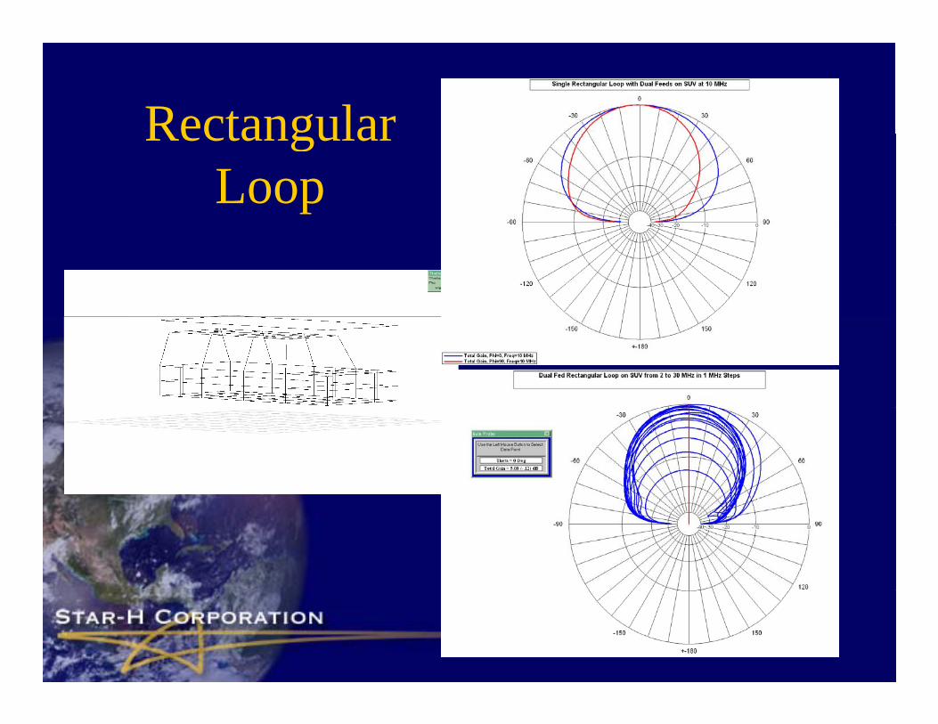
RectangularRectangular Loop

HMMWV/TOCHMMWV/TOC

2 MH C i2 MHz ComparisonBlue = Loop Red = Bent Whip

7 MH C i7 MHz ComparisonBlue = Loop Red = Bent Whip

12 MH C i12 MHz ComparisonBlue = Loop Red = Bent Whip

Low-Angle Mode

Inp t ImpedanceInput Impedanceat radio connector, NVIS mode Measured
Real = top Imag = bottom
2 00E+01
2.50E+01
3.00E+01
3.50E+01NEC PredictedReal = red, Imag = blue
Real top, Imag bottom
0 00E+00
5.00E+00
1.00E+01
1.50E+01
2.00E+01
Series1
0.00E+00
2000
000
3679
664
5359
328
7038
992
8718
656
1039
8320
1207
7984
1375
7648
1543
7312
1711
6976
1879
6640
2047
6304
2215
5968
2383
5632
2551
5296
2719
4960
2887
4624
1 50E+02
2.00E+02
2.50E+02
-5.00E+01
0.00E+00
5.00E+01
1.00E+02
1.50E+02
2000
000
3819
636
5639
272
7458
908
9278
544
1109
8180
1291
7816
1473
7452
1655
7088
1837
6724
2019
6360
2201
5996
2383
5632
2565
5268
2747
4904
2929
4540
Series1
-2.50E+02
-2.00E+02
-1.50E+02
-1.00E+022 3 5 7 9 11 12 14 16 18 20 22 23 25 27 29

Matching LossesResults for 35’ Bent Whip on HMMWV over Average Ground
With 3 meters of 9913 type coaxial cableWith 3 meters of 9913 type coaxial cable
Freq. (MHz)
R X Antenna Gain at Zenith
Tuner and Transmission
Line Loss (3 m 9913)
Net Gain at Zenith
Power into
Antenna for 150W
inputinput2 7.05 -1074 -7 dB 11.88 dB -18.88 dB 9.7 W
7 34.4 -67.1 -0.7 dB 0.12 dB -0.82 dB 145.8 W
12 247.3 497.1 2.82 dB 0.45 dB 2.37 dB 135.3 W
17 485.2 -875 5.15 dB 0.92 dB 4.23 dB 121.4 W
22 82.8 -112 5.39 dB 0.21 dB 5.18 dB 142.9 W
29 304.6 488.8 4 dB 0.71 dB 3.29 dB 127.4 W
Low-pass L network, QC = 1000, QL = 200

Matching LossesResults for 3” Diameter Loop no HMMWV over Average GroundUsing 2 meters of 7/8 Heliax to T, 3 meters of ½” Heliax to RadioUsing 2 meters of 7/8 Heliax to T, 3 meters of ½ Heliax to Radio
No loading or optimization of antennaFreq. (MHz)
R X AntennaGain at Zenith
Tuner and Transmission
Line Loss (Heliax)
Net Gain at Zenith
Power into
Antenna for 150W(Heliax) for 150W
input
2 0.817 -3888 -6.6 dB 34.79 dB -41.4 dB 0.05 W
7 2 03 1081 1 86 dB 18 51 dB 16 65 dB 2 1 W7 2.03 -1081 1.86 dB 18.51 dB -16.65 dB 2.1 W
12 5.05 -591.6 4.58 dB 9.46 dB -4.88 dB 16.99 W
17 11.5 -372.4 5.11 dB 4.90 dB 0.21 dB 48.5 W
22 23.59 -238.1 5.68dB 1.83 dB 3.85 dB 98.4 W
29 42 7 142 5 97 dB 0 56 dB 5 41 dB 131 9 W29 42.7 -142 5.97 dB 0.56 dB 5.41 dB 131.9 W
Low-pass L network, QC = 1000, QL = 200

System Gain ComparisonSystem Gain ComparisonNo system optimization on dual loop antenna
Zenith Gain of Bent Whip and Dual Loop
0
10
-20
-10
02 7 12 17 22 29
ain,
dB
i
32' Bent WhipNVIS Dual Loop
-40
-30Net G
a
16' Bent Whip
-50
Frequency, MHz

Full-Scale Testing
4’ 6” long-7/8” dia. Coax jumper
T-Connector
3/4” Copper Tubing
Coax jumper
7’ 7” long -7/8” dia. Coax to Radio Set Inside TOC
Insulated Feed Gap with Ferrite Balun(one each side)

Full-Scale Testing Results
• NVIS and Low-Angle pattern switching was verified.
• Conducted successful NVIS communications over mountainous terrain using both amateur and
/ i i hAN/VRC-100 transceivers with ATU’s.• Conducted successful long-range communications
b t C t l PA d Vi i i B h VAbetween Central PA and Virginia Beach,VA.

Full-Scale Testing Conclusions
• ATU’s can match to the antenna, but transmission line losses are too high.
d d ddi i l k i• Need to do additional work to improve antenna impedance (larger diameter radiator, multiple turns, distributed loading).turns, distributed loading).
• Move first stage of matching to antenna feedpoints to reduce losses. Initial work shows +10 dB improvement at 2 MHz.
• Look at revolutionary concepts: active antenna for i d t it?receive and transmit?
Contributors
• Christopher Wantuck, CECOM Tactical Radio• Dr. James K. Breakall, Penn State University, y• Milton D. Machalek, STAR-H Corporation• Jon Arent, STAR-H Corporation, p