Embed Size (px)
Citation preview
COMPACT ANTENNAS FOR UWB APPLICATIONS
Taeyoung Yang, Seong-Youp Suh, Randall Nealy, William A. Davis, and Warren L. Stutzman Virginia Tech Antenna Group, Bradley Dept. of Elec. & Comp. Engineering
Virginia Tech, Blacksburg, VA 24061-0111 [email protected], [email protected], [email protected], [email protected], [email protected]
Abstract— This paper reports on an investigation of spherical, disc, and half-disc antennas in the frequency and time domains with the objective of developing small planar versions of the antennas. These antennas have an omni-directional impulse response in azimuth and a pulse duration of 0.5 – 0.65 nanoseconds. In addition, the measured data show a reasonable peak received signal in a pulse communication link using two identical antennas.
Keywords-Ultra wideband, Impulse response, UWB antenna, Spherical antenna, Disc antenna, Half-disc antenna
I. INTRODUCTION Since the United States Federal Communications Commission (FCC) adopted the first UWB Report and Order on February 14, 2002, the interest in UWB technology has increased substantially in both academics and the market place. Interest is stimulated by the expectation that UWB can solve the shortage of the available frequency resources. UWB also represents potential for higher data throughput.
There are many issues involved in designing UWB systems, such as antenna design, interference, propagation and channel effects, and modulation methods. Designing the UWB antenna can be one of the most challenging of these issues. UWB antennas must cover an extremely wide band, 3.1 GHz to 10.6 GHz for the indoor and handheld UWB applications, have electrically small size, and hold a reasonable impedance match over the band for high efficiency. In addition, they are required to have a non-dispersive characteristic in time and frequency, providing a narrow, pulse duration to enhance a high data throughput.
Antennas in the frequency domain are typically characterized by radiation pattern, directivity, efficiency, gain, and bandwidth [1]. In addition, there exist clear standard definitions related to antenna performance in the frequency domain [2]. However, time domain, antenna characterization is a different story. Some have tried to define antenna characterization factors in the time domain and also relate frequency and time domain characteristics [3,4]. However, these characterization methods do not provide easy design processes for UWB antennas to satisfy the critical performance factors such as phase dispersion, peak pulse amplitude (efficiency), pulse width (data rate), and omni-directional impulse
response. In this paper we investigate UWB antennas with those critical performance factors in mind.
We present the spherical, disc, and half-disc antennas in terms of the voltage-standing-wave ratio (VSWR), the phase linearity between two identical antennas, and the impulse responses versus azimuth and elevation. In addition, we also examine the pulse duration, the omni-directional, radiation characteristic in the time domain, and the potential occurrence of a chirp or ringing response. Our goal is to obtain a practical UWB antenna with a very small size, a planar structure, and a low fabrication cost with simplicity for mass production.
II. MEASUREMENT SETUP All antenna tests were performed using two identical antennas with an HP 8510 network analyzer [5] in both the time and frequency domains in the Virginia Tech Antenna Group (VTAG) anechoic chamber. The antennas were oriented in a co-polarized manner and separated by 40” distance to be in the far field. The picture of setup is depicted in Fig. 1.
Figure 1. The measurement setup
III. ANTENNA GEOMETRY AND MEASUREMENTS
In this section, we describe some very small planar UWB antennas. We first investigate a spherical antenna. Then, we examine variations of the spherical antennas in the form of disc and half-disc antennas.
40”
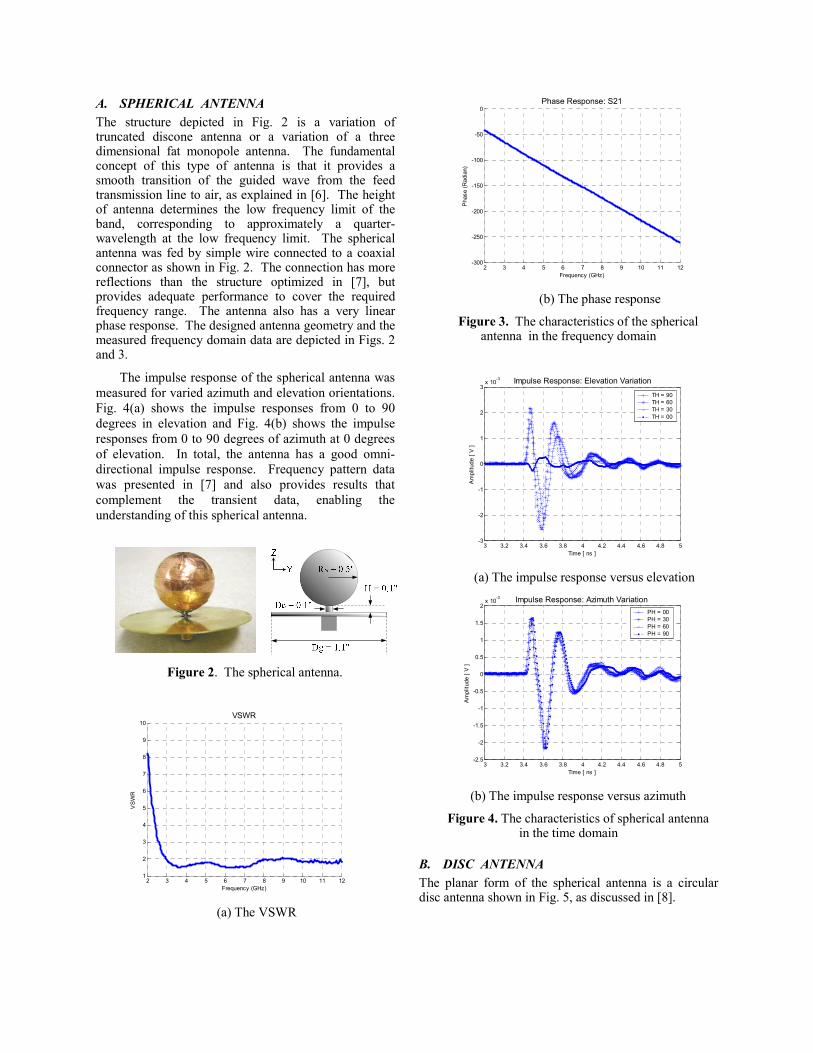
A. SPHERICAL ANTENNA The structure depicted in Fig. 2 is a variation of truncated discone antenna or a variation of a three dimensional fat monopole antenna. The fundamental concept of this type of antenna is that it provides a smooth transition of the guided wave from the feed transmission line to air, as explained in [6]. The height of antenna determines the low frequency limit of the band, corresponding to approximately a quarter-wavelength at the low frequency limit. The spherical antenna was fed by simple wire connected to a coaxial connector as shown in Fig. 2. The connection has more reflections than the structure optimized in [7], but provides adequate performance to cover the required frequency range. The antenna also has a very linear phase response. The designed antenna geometry and the measured frequency domain data are depicted in Figs. 2 and 3.
The impulse response of the spherical antenna was measured for varied azimuth and elevation orientations. Fig. 4(a) shows the impulse responses from 0 to 90 degrees in elevation and Fig. 4(b) shows the impulse responses from 0 to 90 degrees of azimuth at 0 degrees of elevation. In total, the antenna has a good omni-directional impulse response. Frequency pattern data was presented in [7] and also provides results that complement the transient data, enabling the understanding of this spherical antenna.
Figure 2. The spherical antenna.
2 3 4 5 6 7 8 9 10 11 121
2
3
4
5
6
7
8
9
10VSWR
Frequency (GHz)
VS
WR
(a) The VSWR
2 3 4 5 6 7 8 9 10 11 12-300
-250
-200
-150
-100
-50
0Phase Response: S21
Frequency (GHz)
Pha
se(R
adia
n)
(b) The phase response
Figure 3. The characteristics of the spherical antenna in the frequency domain
3 3.2 3.4 3.6 3.8 4 4.2 4.4 4.6 4.8 5-3
-2
-1
0
1
2
3x 10
-3 Impulse Response: Elevation Variation
Time [ ns ]
Am
plitu
de[V
]
TH = 90TH = 60TH = 30TH = 00
(a) The impulse response versus elevation
3 3.2 3.4 3.6 3.8 4 4.2 4.4 4.6 4.8 5-2.5
-2
-1.5
-1
-0.5
0
0.5
1
1.5
2x 10
-3 Impulse Response: Azimuth Variation
Time [ ns ]
Am
plitu
de[V
]
PH = 00PH = 30PH = 60PH = 90
(b) The impulse response versus azimuth
Figure 4. The characteristics of spherical antenna in the time domain
B. DISC ANTENNA The planar form of the spherical antenna is a circular disc antenna shown in Fig. 5, as discussed in [8].
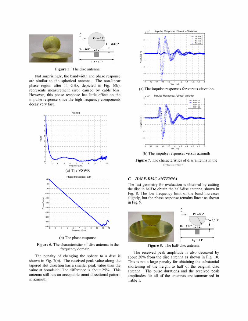
Figure 5. The disc antenna.
Not surprisingly, the bandwidth and phase response are similar to the spherical antenna. The non-linear phase region after 11 GHz, depicted in Fig. 6(b), represents measurement error caused by cable loss. However, this phase response has little effect on the impulse response since the high frequency components decay very fast.
2 3 4 5 6 7 8 9 10 11 121
2
3
4
5
6
7
8
9
10VSWR
Frequency (GHz)
VS
WR
(a) The VSWR
2 3 4 5 6 7 8 9 10 11 12-240
-220
-200
-180
-160
-140
-120
-100
-80
-60
-40Phase Response: S21
Frequency (GHz)
Pha
se(R
adia
n)
(b) The phase response
Figure 6. The characteristics of disc antenna in the frequency domain
The penalty of changing the sphere to a disc is shown in Fig. 7(b). The received peak value along the tapered slot direction has a smaller peak value than the value at broadside. The difference is about 25%. This antenna still has an acceptable omni-directional pattern in azimuth.
3 3.2 3.4 3.6 3.8 4 4.2 4.4 4.6 4.8 5-4
-3
-2
-1
0
1
2
3x 10
-3 Impulse Response: Elevation Variation
Time [ ns ]
Am
plitu
de[V
]
TH = 90TH = 60TH = 30TH = 00
(a) The impulse responses for versus elevation
3 3.2 3.4 3.6 3.8 4 4.2 4.4 4.6 4.8 5-4
-3
-2
-1
0
1
2
3x 10
-3 Impulse Response: Azimuth Variation
Time [ ns ]
Am
plitu
de[V
]
PH = 00PH = 30PH = 60PH = 90
(b) The impulse responses versus azimuth
Figure 7. The characteristics of disc antenna in the time domain
C. HALF-DISC ANTENNA The last geometry for evaluation is obtained by cutting the disc in half to obtain the half-disc antenna, shown in Fig. 8. The low frequency limit of the band increases slightly, but the phase response remains linear as shown in Fig. 9.
Figure 8. The half-disc antenna
The received peak amplitude is also deceased by about 20% from the disc antenna as shown in Fig. 10. This is not a large penalty for obtaining the substantial shortening of the height to half of the original disc antenna. The pulse durations and the received peak amplitudes for all of the antennas are summarized in Table 1.

2 3 4 5 6 7 8 9 10 11 121
2
3
4
5
6
7
8
9
10VSWR
Frequency (GHz)
VS
WR
(a) The VSWR
2 3 4 5 6 7 8 9 10 11 12-300
-250
-200
-150
-100
-50
0Phase Response: S21
Frequency (GHz)
Pha
se(R
adia
n)
(b) The phase response
Figure 9. The characteristics of the half-disc antenna in the frequency domain
IV. CONCLUSIONS The spherical, disc, and half-disc antennas were investigated with respect to pulse duration, peak amplitude, and time-domain, omni-directional radiation characteristics. The phase responses were quite linear over the indoor/handheld UWB application frequency range, and showed good omni-directional impulse responses versus azimuth. These investigations indicate the antennas are good candidates for UWB applications.
3 3.2 3.4 3.6 3.8 4 4.2 4.4 4.6 4.8 5-4
-3
-2
-1
0
1
2
3x 10
-3 Impulse Response: Elevation Variation
Time [ ns ]
Am
plitu
de[V
]
TH = 90TH = 60TH = 30TH = 0
(a) The impulse responses versus elevation
3 3.2 3.4 3.6 3.8 4 4.2 4.4 4.6 4.8 5-3
-2.5
-2
-1.5
-1
-0.5
0
0.5
1
1.5x 10
-3 Impulse Response: Azimuth Variation
Time [ ns ]
Am
plitu
de[V
]
PH = 00PH = 30PH = 60PH = 90
(b) The impulse responses versus azimuth
Figure 10. The characteristics of half-disc antenna in the time domain
Table 1. Summary of the time domain performance
Antenna Pulse Duration [ns]*
Relative Received Peak
Amplitude Sphere 0.65 1.00
Disc 0.6 1.56
Half Disc 0.5 1.33 *to the level that the tail response decays to 15% of the pulse peak
REFERENCES [1] W. L. Stutzman and G.A. Thiele, Antenna Theory and Design
2nd edition, John Wiley & Sons, New York, 1998 [2] Antenna Standards Committtee of the IEEE Antennas and
Propagation Society, IEEE Standard definitions of Tems for Antennas, IEEE Std 145-1993, The Institute of Electrical and Electronics Engineeris, Inc, New York, 1993
[3] E. G. Farr and C. E. Baum, and C. J. Buchenauer, “Impulse Radiating Antennas, Part II, pp. 159-178 in L. Carin et al (eds.), Ultra Wideband/Short-Pulse Electromagnetics 2, Plenum Press, New York, 1995.
[4] Amir Shlivinski, Ehud Heyman, Raphal Kastner, “Antenna Characterization in the Time Domain,” IEEE Transactions on Antennas and Propagations, vol. AP-45, No. 7, pp. 1140-1149, July 1997,
[5] S. Licul, J. N. A. Noronha, C. R. Anderson, T. M. Bielawa, W. A. Davis, D. G. Sweeney, "A Parametric Study of Time-Domain Characteristics of Possible UWB Architectures," submitted to Vehicular Technology Conference, Fall 2003.
[6] John. D. Kraus, Antennas, McGraw-Hill, New York, 1950. [7] Takuya Taniguchi and Takehiko Kobayashi, “An
Omnidirectional and Low-VSWR Antenna for the FCC –Approved UWB Frequency Band,” IEEE Antennas and Propagation Society International Symposium Digest, Vol 3, pp. 460-463, June 2003
[8] S. Honda, M. Ito, H. Seki, and Y. Jinbo, “A disc monopole antenna with 1:8 impedance bandwidth and omni-directional radiation pattern,” Proc. ISAP ‘92(Sapporo, Japan), pp. 1145-1148, Sep. 1992
![A TWO-PORT ANTENNA FOR WIRELESS-POWERED UWB-RFID … · 2.1. Circularly-Polarized UWB Quasi-Spiral Antenna Spiral antennas [16{18] are widely investigated for UWB antenna designs](https://img.dokumen.tips/doc/110x75/60cd00d2fbca443dcb07fa71/a-two-port-antenna-for-wireless-powered-uwb-rfid-21-circularly-polarized-uwb-quasi-spiral.jpg)