Embed Size (px)
Citation preview

Communication Networks (0368-3030) / Fall 2013
The Blavatnik School of Computer Science, Tel-Aviv University
Allon Wagner

Kurose & Ross, Chapters 5.5 - 5.6 (5th ed.)
Tanenbaum & Wetherall, Chapters 4.3.4 – 4.3.8 (5th ed.)
Many slides adapted from:
J. Kurose & K. Ross \ Computer Networking: A Top Down Approach (5th ed.) Addison-Wesley, April 2009.
Copyright 1996-2010, J.F Kurose and K.W. Ross, All Rights Reserved.
Data Link Layer 5-3
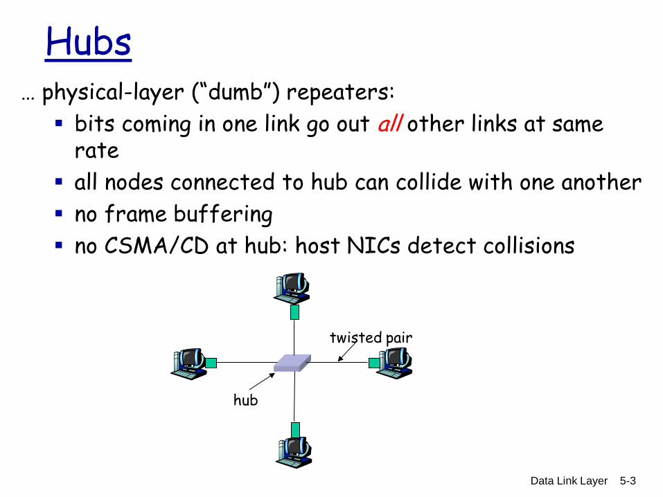
Hubs … physical-layer (“dumb”) repeaters:
bits coming in one link go out all other links at same rate
all nodes connected to hub can collide with one another
no frame buffering
no CSMA/CD at hub: host NICs detect collisions
twisted pair
hub
Data Link Layer 5-4
Switch
link-layer device: smarter than hubs, take active role store, forward Ethernet frames
examine incoming frame’s MAC address, selectively forward frame to one-or-more outgoing links when frame is to be forwarded on segment, uses CSMA/CD to access segment
transparent hosts are unaware of presence of switches
plug-and-play, self-learning switches do not need to be configured
Data Link Layer 5-5
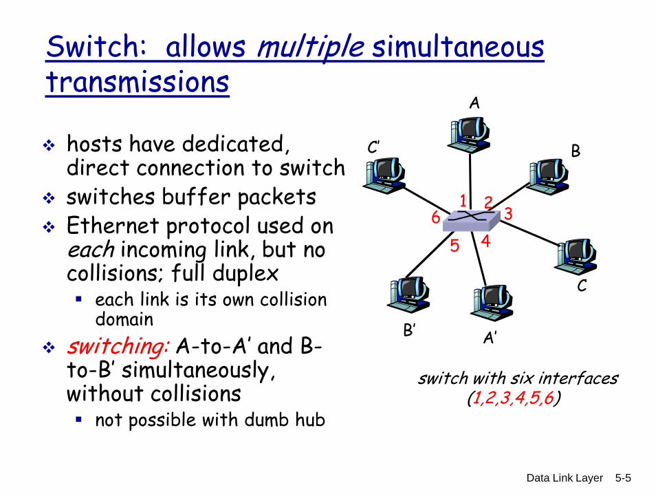
Switch: allows multiple simultaneous transmissions
hosts have dedicated, direct connection to switch
switches buffer packets Ethernet protocol used on
each incoming link, but no collisions; full duplex each link is its own collision
domain
switching: A-to-A’ and B-to-B’ simultaneously, without collisions not possible with dumb hub
A
A’
B
B’
C
C’
switch with six interfaces (1,2,3,4,5,6)
1 2 3
4 5
6
Data Link Layer 5-6
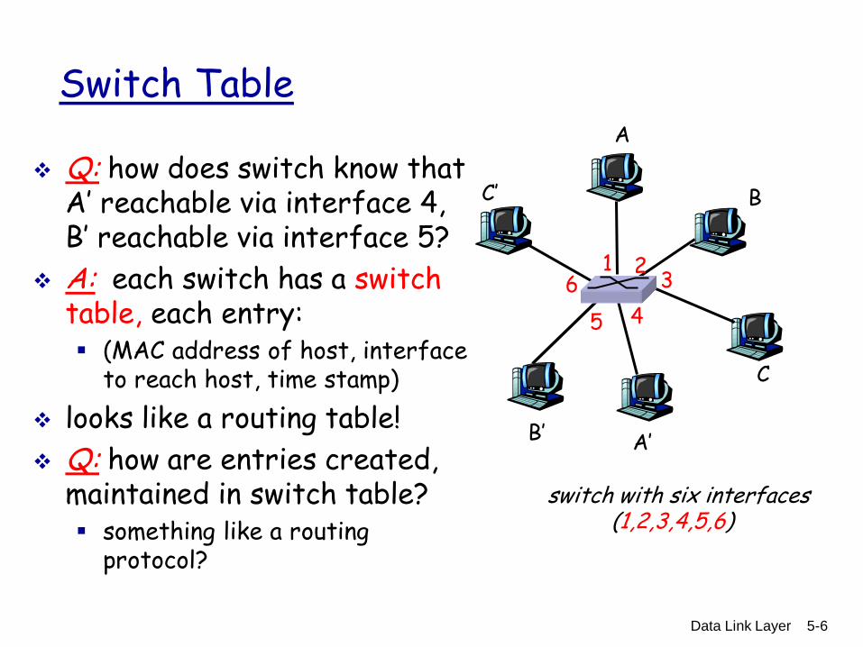
Switch Table
Q: how does switch know that A’ reachable via interface 4, B’ reachable via interface 5?
A: each switch has a switch table, each entry: (MAC address of host, interface
to reach host, time stamp)
looks like a routing table!
Q: how are entries created, maintained in switch table? something like a routing
protocol?
A
A’
B
B’
C
C’
switch with six interfaces (1,2,3,4,5,6)
1 2 3
4 5
6

Data Link Layer 5-7
Switch: self-learning
switch learns which hosts can be reached through which interfaces when frame received,
switch “learns” location of sender: incoming LAN segment
records sender/location pair in switch table
A
A’
B
B’
C
C’
1 2 3
4 5
6
A A’
Source: A Dest: A’
MAC addr interface TTL
Switch table (initially empty)
A 1 60
Data Link Layer 5-8
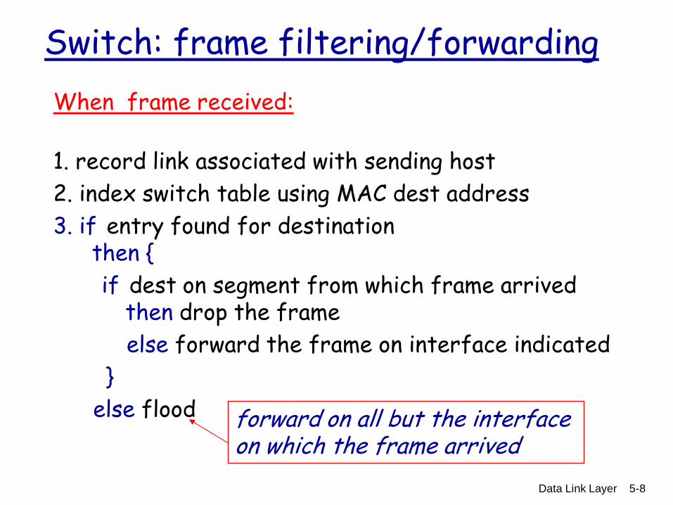
Switch: frame filtering/forwarding
When frame received:
1. record link associated with sending host
2. index switch table using MAC dest address
3. if entry found for destination then {
if dest on segment from which frame arrived then drop the frame
else forward the frame on interface indicated
}
else flood
forward on all but the interface on which the frame arrived
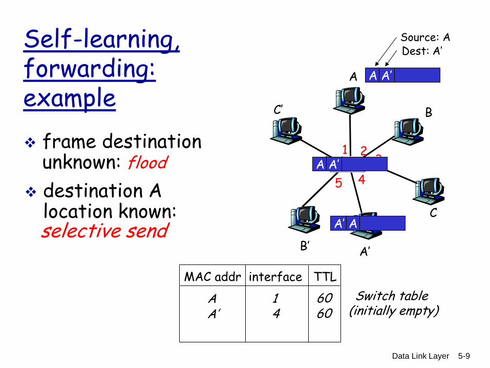
Data Link Layer 5-9
Self-learning, forwarding: example
A
A’
B
B’
C
C’
1 2 3
4 5
6
A A’
Source: A Dest: A’
MAC addr interface TTL
Switch table (initially empty)
A 1 60
A A’ A A’ A A’ A A’ A A’
frame destination unknown: flood
A’ A
destination A location known:
A’ 4 60
selective send
Data Link Layer 5-10
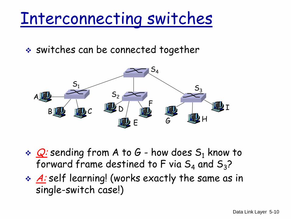
Interconnecting switches
switches can be connected together
A
B
Q: sending from A to G - how does S1 know to forward frame destined to F via S4 and S3?
A: self learning! (works exactly the same as in single-switch case!)
S1
C D
E
F S2
S4
S3
H
I
G

Data Link Layer 5-11
Self-learning multi-switch example
Suppose C sends frame to I, I responds to C
Q: show switch tables and packet forwarding in S1, S2, S3, S4
A
B
S1
C D
E
F S2
S4
S3
H
I
G
1
2
Data Link Layer 5-12
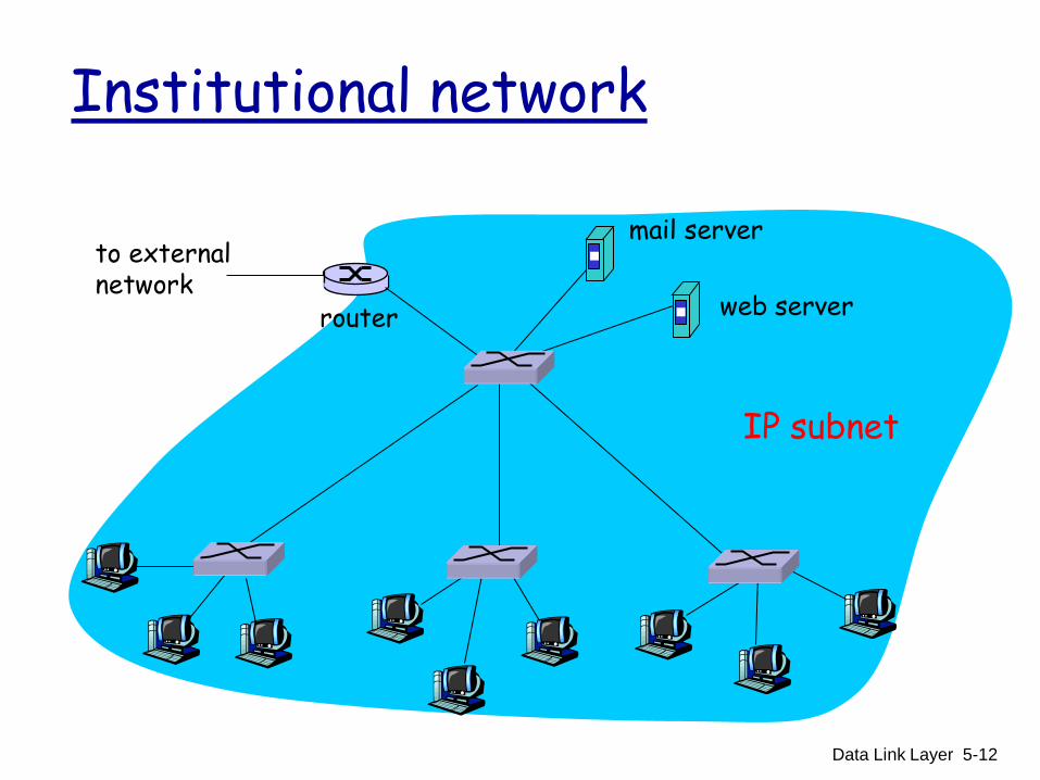
Institutional network
to external network
router
IP subnet
mail server
web server
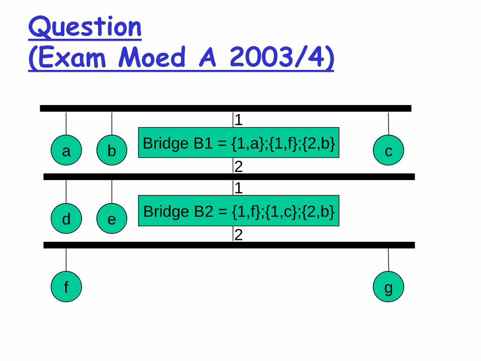
Question (Exam Moed A 2003/4)
Bridge B1 = {1,a};{1,f};{2,b} a b c
1
2
Bridge B2 = {1,f};{1,c};{2,b} d e
1
2
f g
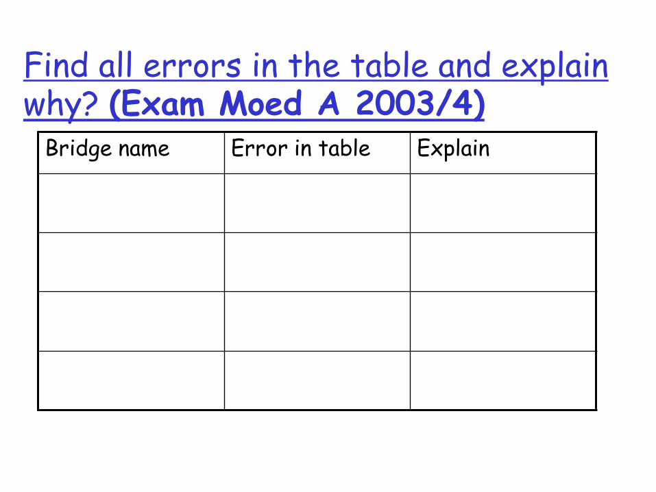
Find all errors in the table and explain why? (Exam Moed A 2003/4)
Bridge name Error in table Explain
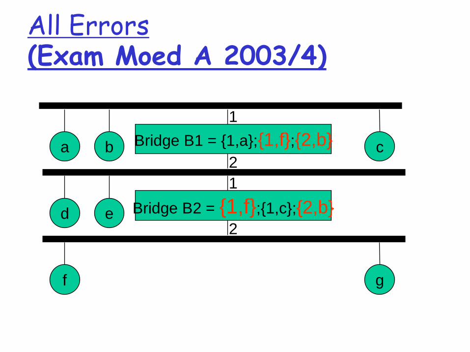
All Errors (Exam Moed A 2003/4)
Bridge B1 = {1,a};{1,f};{2,b} a b c
1
2
Bridge B2 = {1,f};{1,c};{2,b} d e
1
2
f g
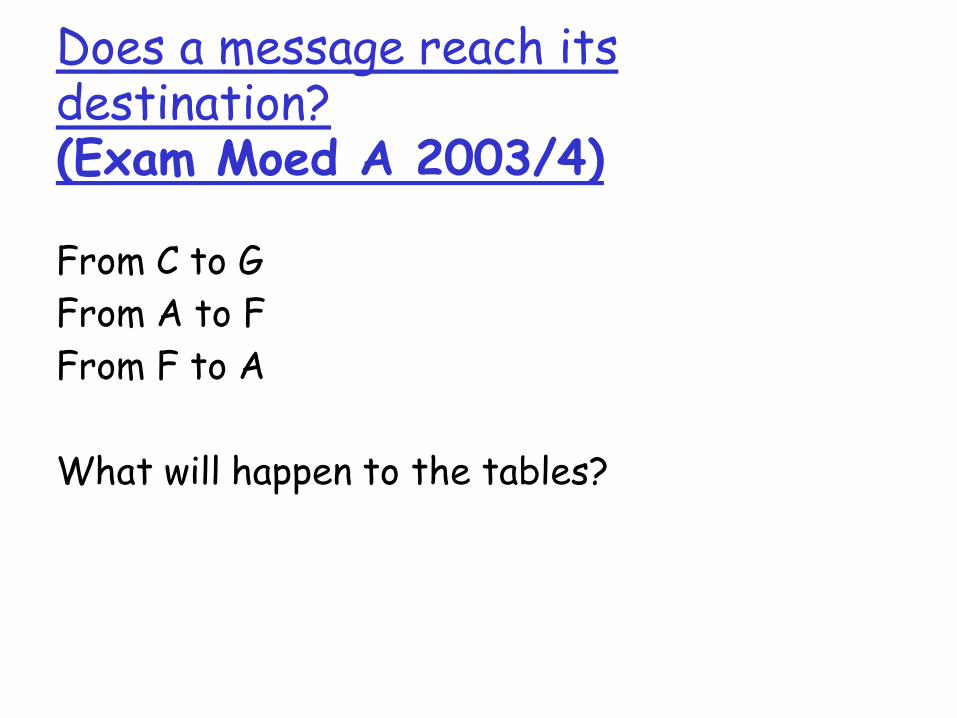
Does a message reach its destination? (Exam Moed A 2003/4)
From C to G
From A to F
From F to A
What will happen to the tables?

From C to G
Bridge B1 = {1,a};{1,f};{2,b}{1,c} a b c
1
2
Bridge B2 = {1,f};{1,c};{2,b} d e
1
2
f g

From A to F
Bridge B1 = {1,a};{1,f};{2,b} a b c
1
2
Bridge B2 = {1,f};{1,c};{2,b} d e
1
2
f g

From F to A
Bridge B1 = {1,a};{ ,f};{2,b} a b c
1
2
Bridge B2 = { ,f};{1,c};{2,b} d e
1
2
f g 2
1
1 2
1 2

Lecture 3 #20
What will happen with loops? Incorrect learning
A
B
1 1
2 2
A , 1 A , 1 2 2
Lecture 3 #21
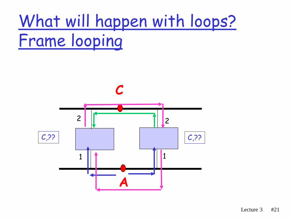
What will happen with loops? Frame looping
A
C
1 1
2 2
C,?? C,??

Lecture 3 #22
What will happen with loops? Frame looping
A
B
1 1
2 2
B,2 B,1

Lecture 3 #23
Loop-free: tree
A
B
C
A message from A will mark A’s location
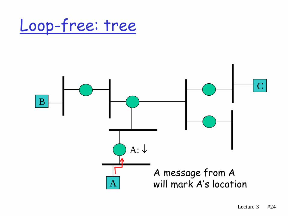
Lecture 3 #24
Loop-free: tree
A
B
C
A message from A will mark A’s location
A:
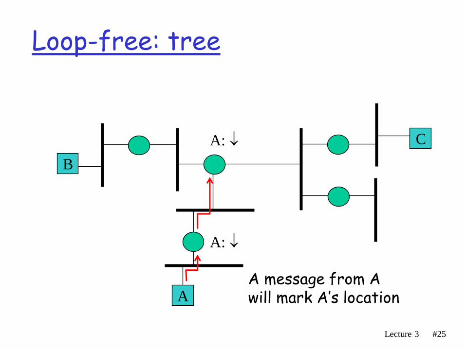
Lecture 3 #25
Loop-free: tree
A
B
C A:
A:
A message from A will mark A’s location
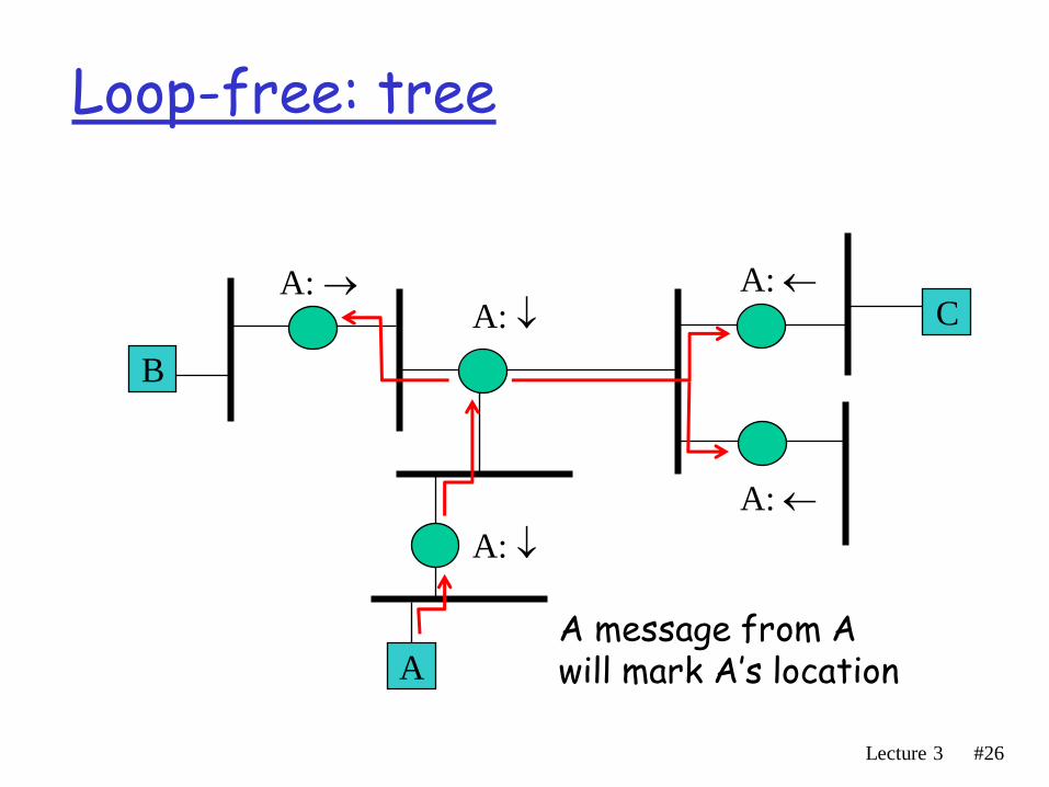
Lecture 3 #26
Loop-free: tree
A
B
C A: A:
A:
A:
A:
A message from A will mark A’s location

Lecture 3 #27
Loop-free: tree
A
B
C A: A:
A:
A:
A:
A message from A will mark A’s location

Lecture 3 #28
Loop-free: tree
A
B
C
A:
A: A:
A:
A:
So a message to A will go by marks…
A message from A will mark A’s location

Perlman, Chapters 3.3 - 3.5 (2th ed.)
Peterson & Davie, Chapter 3.2.2 (3th ed.)

Introduction
• Developed by Radia Perlman • Standardized in IEEE 802.1 ▫ We will learn the main concepts, and skip some of the
technical drudgery ▫ Refer to Perlman’s book or to the standard for a
complete description
• Bridges run a distributed spanning tree algorithm ▫ Select which ports (and bridges) should actively
forward frames ▫ Dynamic, adapts itself to topology changes

STP’s goal
• Create a spanning-tree of the LAN segments in the extended LAN
• This is done by logically removing ports from the network in order to reduce it to an acyclic graph ▫ Data traffic is discarded upon receipt in ports not
selected for inclusion in the spanning tree.
▫ Sometimes, an entire bridge will be removed from the network

STP preliminaries
• Bridges regularly exchange frames known as Configuration Bridge Protocol Data Units (Configuration BPDUs).
• Every bridge has a unique ID. The bridge with the smallest ID is the root bridge.
• Each config message transmitted by bridge B contains: ▫ Root ID: ID of the bridge R which B currently considers to
be the root ▫ Cost: Least cost path from B to R (of all the paths B is
currently aware of) ▫ Transmitting Bridge ID: B’s ID.
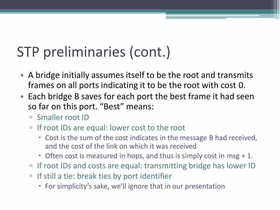
STP preliminaries (cont.)
• A bridge initially assumes itself to be the root and transmits frames on all ports indicating it to be the root with cost 0.
• Each bridge B saves for each port the best frame it had seen so far on this port. “Best” means: ▫ Smaller root ID ▫ If root IDs are equal: lower cost to the root
Cost is the sum of the cost indicates in the message B had received, and the cost of the link on which it was received
Often cost is measured in hops, and thus is simply cost in msg + 1.
▫ If root IDs and costs are equal: transmitting bridge has lower ID ▫ If still a tie: break ties by port identifier
For simplicity’s sake, we’ll ignore that in our presentation

Example 1 (adapted from Perlman)
C1
Transmitter Cost Root ID
35 15 29
80 15 35
39 80 35
C2
Transmitter Cost Root ID
32 12 31
38 18 35
40 80 35
• In all three case, config message C1 is better than C2 (assuming cost is hops)
1. Smaller root ID
2. Smaller distance to the same root
3. Same root and distance, but through a bridge with smaller ID.
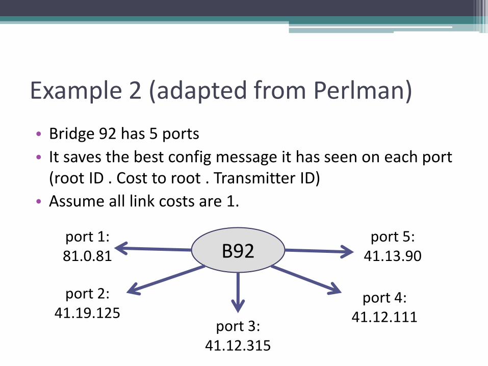
Example 2 (adapted from Perlman)
• Bridge 92 has 5 ports
• It saves the best config message it has seen on each port (root ID . Cost to root . Transmitter ID)
• Assume all link costs are 1.
B92 port 1: 81.0.81
port 2: 41.19.125
port 3: 41.12.315
port 4: 41.12.111
port 5: 41.13.90

Example 2 (cont.)
• Bridge 92 assumes the root is 41 and best distance to it is 12 + 1 = 13.
• B41 can be reached in cost 13 either via B315 or via B111. B111 is chosen (smaller ID than B315).
• B92 can transmit the message 41.13.92
B92 port 1: 81.0.81
port 2: 41.19.125
port 3: 41.12.315
port 4: 41.12.111
port 5: 41.13.90

Selection of Root Port
• Every bridge B accepts one bridge as the root ▫ the smallest root ID indicating on any of the ports, or B
itself if its ID is even smaller
• B can now select its Root Port ▫ the port which indicated the least cost to R
▫ will be used to transfer messages towards the root
Selection of Designated Ports
• For every LAN segment B is connected to B decides whether it is the designated bridge for that LAN: ▫ if its config message is the best it had seen on this LAN ▫ In that case, the corresponding port becomes the
designated port for that LAN. ▫ B will be responsible to delivering data frames from
the root towards this LAN via the designated port
• A designated port is never also a root port (Why?) • All the ports of the root bridge are designated
(Why?)

Selecting spanning tree ports
• B forwards data messages only on its root port and its designated ports. Other ports discard data messages upon receipt. ▫ It might even be that entire bridges are removed from
the network
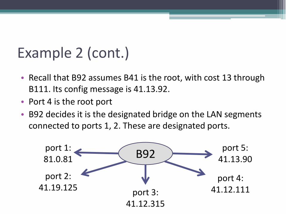
Example 2 (cont.)
• Recall that B92 assumes B41 is the root, with cost 13 through B111. Its config message is 41.13.92.
• Port 4 is the root port
• B92 decides it is the designated bridge on the LAN segments connected to ports 1, 2. These are designated ports.
B92 port 1: 81.0.81
port 2: 41.19.125
port 3: 41.12.315
port 4: 41.12.111
port 5: 41.13.90
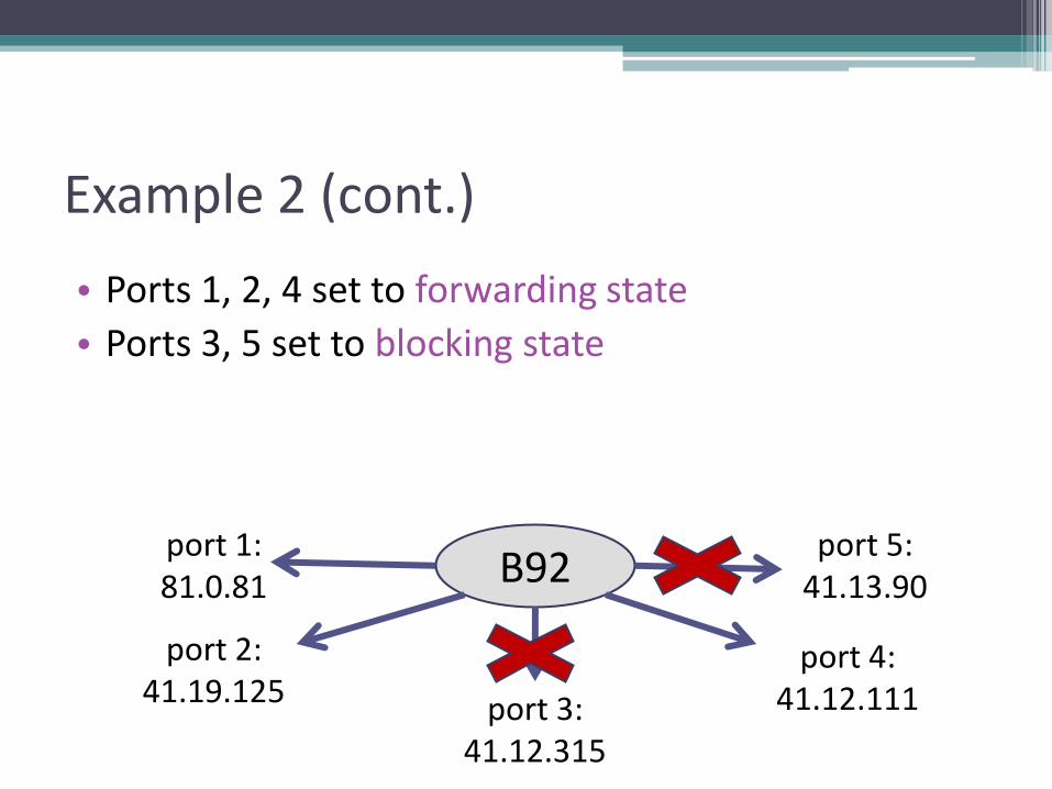
Example 2 (cont.)
• Ports 1, 2, 4 set to forwarding state
• Ports 3, 5 set to blocking state
B92 port 1: 81.0.81
port 2: 41.19.125
port 3: 41.12.315
port 4: 41.12.111
port 5: 41.13.90

Example 2 (cont.)
• If the bridge’s ID had been 15, it would have decided it was the root port, transmitting the message 15.0.15
• All its ports would have become designated
B15 port 1: 81.0.81
port 2: 41.19.125
port 3: 41.12.315
port 4: 41.12.111
port 5: 41.13.90

Example:
A
C
E
D
B
K
F
H
J
G
I
B3
B7
B4
B2
B5
B1
B6
A
C
E
D
B
K
F
H
J
G
I
B5
B2
B3
B7
B4
B1
B6
B1 is the root bridge
B3 and B5 are both connected to LAN A, but B5 is the designated port since it's closer to root
B5 and B7 are both connected to LAN B, but B5 is the designated port due to smaller ID (equal distance).
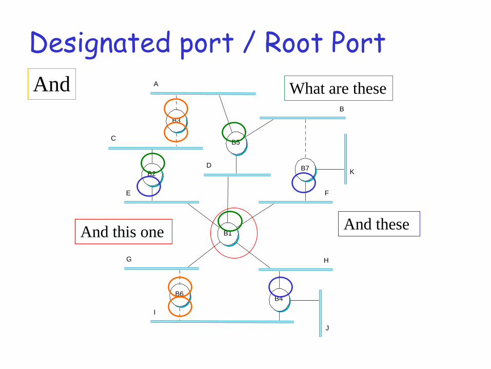
Designated port / Root Port A
C
E
D
B
K
F
H
J
G
I
B5
B2
B3
B7
B4
B1
B6
What are these
And these And this one
And
STP Stabilization
• Recall that a bridge initially assumes itself to be the root and transmits frames on all ports indicating it to be the root with cost 0.
• When a bridge B accepts another bridge R as the root, it stops generating config messages on its own. ▫ B transmits config messages on all its designated ports
when triggered to (by Can you see why only on the designated ports?
▫ It adds the relevant link cost (often simply +1) to the cost indicated in them
• When the algorithm stabilizes, only the real root R’ generates config messages, and the other bridges forward them on their designated ports
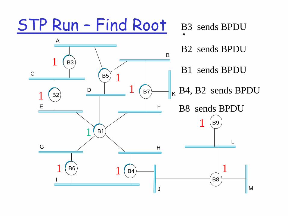
STP Run – Find Root A
C
E
D
B
K
F
H
J
G
I
B3
B7
B4
B2
B5
B1
B6
B8
L
M
B9
3
5
7
4 6
1
2
9
8
B3 sends BPDU
3
B2 sends BPDU
2
2 B1 sends BPDU
2 1
1 1
1
B4, B2 sends BPDU
B8 sends BPDU
1
1
1
1
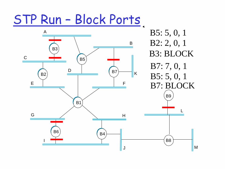
STP Run – Block Ports A
C
E
D
B
K
F
H
J
G
I
B3
B7
B4
B2
B5
B1
B6
B8
L
M
B9
B5: 5, 0, 1
B2: 2, 0, 1
B3: BLOCK
B7: 7, 0, 1
B5: 5, 0, 1 B7: BLOCK
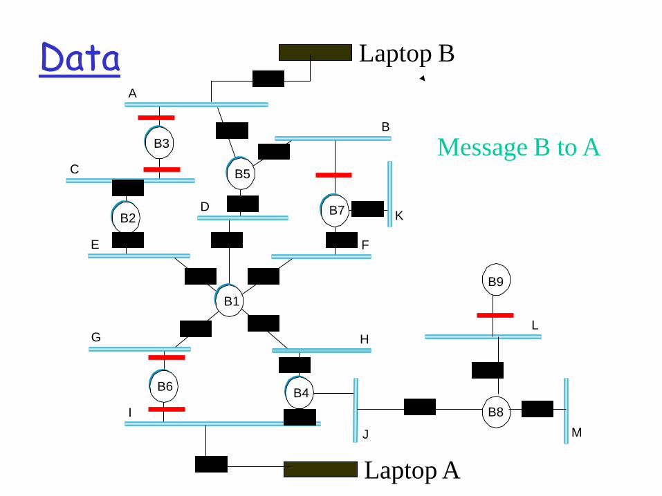
Data A
C
E
D
B
K
F
H
J
G
I
B3
B7
B4
B2
B5
B1
B6
B8
L
M
B9
Laptop A
Laptop B
Message A to B Message B to A
Topology changes
• STP dynamically adapts to link / bridge additions:
• A new bridge / a bridge with a new port will think it is the root / the designated bridge for the LAN until receiving the appropriate config messages ▫ Actually, there are some technicalities here we will not
go into

Topology changes (cont.)
• STP dynamically adapts to link / bridge removal • Recall that every bridge B saves for each port the best
message it had seen on this port • The entry also holds an “age” field (which is reset by
“fresh” config messages). ▫ but not always to 0 – again, technicalities
• When a link / bridge fails or is removed from the network “fresh” config messages might stop arriving on some of B’s ports: ▫ age is increased gradually until the entry expires ▫ the STP algorithm kicks in again: B reselects its assumed
root, cost to root.