Embed Size (px)
Citation preview

Communication Energy Optimization of ElectricVehicle Platoon on Curved RoadWei Gao ( [email protected] )
Beijing University of Posts and Telecommunications https://orcid.org/0000-0002-4860-3519Celimuge Wu
The University of Electro-Communications
Research Article
Keywords: platoon, electric vehicle, communication energy optimization, auxiliary energy systems
Posted Date: September 3rd, 2021
DOI: https://doi.org/10.21203/rs.3.rs-853175/v1
License: This work is licensed under a Creative Commons Attribution 4.0 International License. Read Full License

Gao and Wu
RESEARCH
Communication Energy Optimization ofElectric Vehicle Platoon on Curved RoadWei Gao1* and Celimuge Wu2
Abstract
The cruising range of an electric vehicle is
limited by its battery. Reducing the energy
consumption of MES (main energy systems) or
AES (auxiliary energy systems) of the vehicle
battery is an effective means to increase the
electric vehicle cruising range. Platoon driving
can greatly reduce the wind resistance of the
vehicle and then reduce the energy
consumption of MES for electric vehicles. This
paper proposes an adaptive communication
energy optimization scheme based on road
curvature radius to save the energy of AES for
the electric vehicle platoon on curved roads. In
this paper, the inter-vehicle distance error based
on the car-like model in a two-dimensional
space is established. Then, the inter-vehicle
distance error is used to design a control law K
to accomplish successful platooning. Next, three
platooning control schemes based on different
information flow topologies are discussed.
Finally, the consensus of three platooning
control schemes and the energy consumption of
electric vehicle communication systems are
analyzed by MATLAB’s Simulink. Simulation
results show that the communication energy
optimization scheme reduces the power
consumption of AES as long as the platoon
driving on curved roads.
Keywords: platoon; electric vehicle;
communication energy optimization; auxiliary
energy systems
*Correspondence: [email protected]
1Beijing University of Posts and Telecommunications Beijing, the State Key
Laboratory of Networking and Switching Technology, Beijing, China
Full list of author information is available at the end of the article
1 IntroductionSince electric vehicles (EVs) are considered as zero pollu-
tion for gaseous pollutants, it is one of the most important
reasons for the development of EVs. However, compared
to fuel vehicles, electric vehicles have short cruising dis-
tances. Electric vehicle platoon is a good way to improve
the cruising range of vehicles. Platoon can greatly reduce
wind resistance. But, the frequent communication among
platoon members increases the power consumption of aux-
iliary energy systems for vehicle batteries.
Some auxiliary energy systems (AES), including neces-
sary lighting, heating, and communication are directly re-
lated to the platooning cruise range [1]. Other systems are
in the main energy systems (MES) such as power steer-
ing, brake booster, air conditioner, satellite navigation, etc.
All of them use electrical energy from batteries thus reduce
vehicle cruising range. Among them, wireless communica-
tion of AES is usually considered as an important element
of platooning.
Vehicle platooning is a group of vehicles in a close
manner through wireless communication to achieve safe
and high-speed driving [2] [3]. Control and computing
technologies are integrated together to achieve stability,
consensus, scalability, reliability, efficiency, and safety of
the platooning system by exchanging vehicle information
(such as speed, heading and intentions, etc.) over wire-
less networks to maintain relatively small inter-vehicle dis-
tance [4–7]. Frequent information interaction consumes a
lot of battery power and reduces the cruising range of elec-
tric vehicle platoon.
Cruising range is one of the main obstacles of electric ve-
hicles. In order to overcome it without increasing the bat-
tery size and price of the vehicle, one solution is to con-
duct energy optimization. Most existing electric vehicle en-
ergy optimization methods are conducted for MES, AES
or a collaboration between the two. Thibault et al. propose
model-based strategies to predict and optimize the energy
consumption of a trip [8]. Zhang et al. combine terrain-
information and preceding-vehicle information in energy
management [9]. Xu et al. present two braking regenerative
energy optimization controllers for in-wheel motor electric
vehicles to achieve the braking requirement as well as ef-
fectively promote regenerative efficiency [10]. The above
studies save driving energy of MES with vehicle movement

Gao and Wu Page 2 of 14
prediction to prolong the driving distance for an electric ve-
hicle. In the search for better efficiency, AES for EV is de-
signed. A predictive decision support system is designed to
optimally distribute energy flow between the instantaneous
power demand requested by the driver for the powertrain
engine and the AES such as the heating system [11]. An
ultracapacitor-based AES is designed to greatly reduce the
energy consumption of AES [1]. In addition to considering
MES and AES separately, the joint optimization of these
two systems can also increase vehicle travel distance. Jin et
al. study on the problem of allocating energy from renew-
able sources to EV in a cost-efficient manner [12].
MES and AES are two main systems that determine the
battery consumption level. Reducing the power consump-
tion of subsystems in any system can increase the cruising
range of vehicles. Under the premise of ensuring stable pla-
toons, in order to reduce the battery consumption of elec-
tric vehicles, we propose a method to reduce the commu-
nication energy consumption in the AES. We observe that
when platoons are driven on curved roads, the inter-vehicle
distance and inter-vehicle communication distance are not
equal. Regardless of the manner in which the platoon is
formed, it is necessary to frequently exchange vehicle dy-
namics information between the vehicle and its preceding
vehicles. Therefore, an adaptive radius of curvature com-
munication energy allocation scheme is proposed to save
the energy of AES on curved road.
The main contributions of this paper are as follows:
• Modelling of inter-vehicle distance error of platoon on
curved road is constructed, and a constant control law
K is used to control the error. Simulation results show
that an appropriate constant control law can maintain
the platooning consensus.
• Typical platooning control schemes, namely, the de-
centralized control under PF (predecessor-following),
decentralized control under PLF (predecessor-leader
following), and centralized control by the leader, are
discussed.
• When the platooning reaches a consensus, the pro-
posed energy optimization scheme is superior to the
minimum transmitted power scheme on straight road
and the maximum radius of curvature scheme on
curved road.
The rest of this paper is organized as follows. Com-
munication energy optimization of electric vehicle pla-
toon is proposed in section I. Methods include platoon
under two-dimensional space, platooning control schemes,
and curvature-driven communication mechanism are intro-
duced in section II. Results are discussed in section III.
Concluding remarks and future work are presented in sec-
tion IV.
2 MethodsThe car-like model is the basis for studying the platoon in
a real environment [13]. The car-like model in the two-
dimensional space quantifies the deviation of the vehicle
from the road in a given two-dimensional space. In longi-
tudinal control, the car-like model is used as a placement
platform for the on-board laser and radar sensors to es-
tablish a mathematical model of the inter-vehicle distance.
The placed sensor is used to detect the inter-vehicle dis-
tance, and then transmit the message to the platoon con-
troller to maintain the constant time headway or constant
distance strategy of the platoon, thereby ensuring the lon-
gitudinal safety of the platoon. For example, Godbole and
Lygeros propose the longitudinal control laws to maintain
safe spacing, track an optimal velocity and perform vari-
ous maneuvers (forming, breaking up platoons, and chang-
ing lanes) [14]. In the lateral control, the car-like model is
usually used to establish the relationship between the steer-
ing angle and the road offset, and to calculate the optimal
steering angle when the vehicle is turning. Then the vehi-
cle maintains the distance between the nearest point and
the curved road to ensure the lateral safety of the platoon.
When driving on a curved road, the platoon includes both
longitudinal control and lateral control. For instance, Wei
et al. realize the longitudinal and lateral vehicle following
only by radar and V2V, independent of high-accuracy po-
sitioning system and road marking [15]. Bayuwindra et al.
overcome cut corners by the look-ahead is extended to a
point perpendicular to the direction of the preceding vehi-
cle and then present a novel look-ahead concept for com-
bined longitudinal and lateral vehicle following control for
a car-like platoon [16]. Finally, establishing the lateral devi-
ation under the car-like model is a necessary condition for
establishing the longitudinal inter-vehicle distance error.
2.1 platoon under two-dimensional space
The curved road with varying curvature is established un-
der the two-dimensional space for vehicle platooning. This
method is close to the actual road design and easy to imple-
ment in the program. The movement of the platoon in the
two-dimensional space causes a change in the inter-vehicle
distance. At this time, the platoon stability varies with the
error in the inter-vehicle distance for platooning control.
Typically, inter-vehicle distance errors in the platoon are
related to changes in road curvature and control law.
The curved road having different curvatures are designed,
and curves of different curvatures are connected into curved
roads by adjusting curvature control points. Then, we build
a car-like model in the two-dimensional space. Then, the
inter-vehicle distance error is established under the curva-
ture space, and a constant control law K is added to design
a stable platoon.
2.1.1 Car-like model
Car-like model is composed of a motorized wheeled axle at
the rear of the chassis, and a pair of orientable front steer-
ing wheels. For an easier analytical representation of the

Gao and Wu Page 3 of 14
Car-like model, we put this model into a two-dimensional
space, as represented in Fig. 1. X and Y represent the hori-
zontal and vertical axes of the Cartesian coordinate system,
respectively. The simple kinematic model is described as
follows:
L
X
Y
Direction
of road
X
X
Figure 1 Car-like model.
xi = vit · cosγ i
t , (1a)
yi = vit · sinγ i
t , (1b)
γ it =
vit
L· tan(γ i
t −β it ), (1c)
where vit is the velocity of vehicle i at time t. L is the wheel-
base of the vehicle. γ it is the angle between orientation of
vehicle i at time t and horizontal line with respect to world
frame. β it is the steering angle of vehicle i at time t with re-
spect to world frame. α it is the angle of between orientation
of the tangent to the trajectory at the same point in rela-
tion and horizontal line to the absolute reference. Si∆t is the
curved distance of vehicles i from time t to t +∆t. Given
that Cartesian distance is not monotonous for very curved
trajectories while quantifying the spacing between two con-
secutive vehicles, it is necessary to construct the model in
curvilinear space, that is, with respect to the curvilinear ab-
scissa of the nearest point on the trajectory measured from
the vehicle, as shown follows.−−→GW represents the projection of the Cartesian velocity of
the vehicle into curvilinear space. The vehicle and the road
are offset from the angle of θ it = γ i
t −α it . ci stands for the
respective local curvature of vehicle i, which corresponds
to the reciprocal of the radius of curvature. Si∆t is the further
projection by considering the lateral deviation Dit .
Si∆t =
vitcosθ i
t
1+Ditci
, (2a)
Dit = vi
t · sinθ it , (2b)
θ it = vi
t
✓
tan(γ it −β i
t )
L−
ci · cosθ it
1+ ciDit
◆
. (2c)
Proof: See Appendix A.
2.1.2 Modelling of inter-vehicle distance error
A longitudinal platooning system can be considered as a
combination of four important components: vehicle lon-
gitudinal dynamics, information exchange flow, decentral-
ized or centralized controllers and inter-vehicle distance
policies [20] [27] [28] [29]. In order to analyze longitudi-
nal inter-vehicle distance error, the assumptions of the other
components are as follows:
(1) Vehicle longitudinal dynamics include the engine,
drive line, brake system, aerodynamics drag, etc. In this
paper, we consider that every vehicle has the homogeneous
double-integrator model [30].
(2) Decentralized or centralized controller is adopted in
this paper. Decentralized control is that each vehicle con-
trols its own vehicle status based on other vehicles’ infor-
mation. Centralized control is that all platoon members are
controlled by leader.
SSi i-1 i
i-1
Vehicle location at time t
Vehicle location at time t+ t
Figure 2 Distance error dynamic.
Considering N homogeneous vehicles driving along the
curved road, platoon member (vehicle i) is to follow its pre-
ceding vehicle driving at a desired inter-vehicle distance S.
Two platoon members are schematically depicted in Fig. 2

Gao and Wu Page 4 of 14
with S being the distance between vehicle i and its preced-
ing vehicle i− 1. The main objective of each vehicle is to
follow its preceding vehicle at a desired distance S. But,
inter-vehicle distance will be changed due to sensor delay,
communication delay, weather and curved road, etc. caus-
ing a distance error δ i∆t . Here Si
∆t and Si−1∆t are the curved
distance of vehicles i and i−1 in time ∆t, respectively. Let
us define the curved distance error for the i-th vehicle as:
δ i∆t = Si−1
∆t −Si∆t , (3a)
δ i∆t = Si−1
∆t − Si∆t . (3b)
When ∆t → 0, combining equation (3b) with equation
(2c), we can get the following equation.
δ i∆t =
vi−1t cosθ i−1
t
1+Di−1t ci−1
−vi
tcosθ it
1+Ditci
, (4)
let δ i∆t = K ·δ i
∆t and K > 0. The expression of vehicle speed
is as follows:
vit =
1+Ditci
cosθ it
✓
vi−1t cosθ i−1
t
1+Di−1t ci−1
−Kδ i∆t
◆
, (5)
where the vehicle speed vi−1t and cured distance error δ i
∆t
are used as the control input of vehicle i.
In this section, the inter-vehicle distance error is con-
verged by constant control law K to keep the desired inter-
vehicle distance. In the next section, the cooperation be-
tween multiple vehicles based on different information flow
topologies is discussed.
2.2 platooning control schemes
For multi-vehicle platooning, different controller place-
ment positions will lead to different information flow
topologies. In other words, different information flow
topologies have different suitable platoon controller place-
ment positions. For example, the PF (predecessor-following)
topology is a topology that does not obtain information
about the dynamics of the leader. It is suitable for plac-
ing the controller on each vehicle of the platoon members,
and the vehicle itself will calculate the desired inter-vehicle
distance at each moment. Ghasemi et al. propose a hier-
archical platoon controller design framework, where the
second layer is composed of a decentralized bidirectional
control controller [17]. Due to the lack of dynamics about
the leader, the platoon is likely to lose stability as the num-
ber of vehicles increases [18]. In the PLF (predecessor-
leader following) topology, each vehicle of the platoon can
receive broadcast information from the leader, so the con-
troller can be placed in each vehicle or only in the leader.
When the controller is only placed in the leader, the leader
controls platoon members through the network, which is
called a centralized control platoon. When the controller
is placed in each vehicle, the leader only broadcasts its
dynamics information to platoon members, which is a de-
centralized control platoon. In paper [19], a centralized and
distributed control policy is proposed in which each vehi-
cle’s control decision depends solely on its relative kine-
matics with respect to the leader. In paper [20], for each
topology, Chehardoli et al. propose a new neighbor-based
adaptive control law to deal with adaptive control and iden-
tification of 1-D platoon of non-identical vehicles. There-
fore, platoon control schemes under multi-vehicle mainly
focus on the control and communication topology.
Typical platooning information flow topologies include
predecessor-following (PF) topology, predecessor-leader
following (PLF) topology, bidirectional (BD) topology,
bidirectional-leader (BDL) topology, two-predecessors fol-
lowing (TPF) topology, and two-predecessor-leader follow-
ing (TPLF) topology [31] [32]. These information flow
topologies are classified from the mode of transmitting the
information. The simplex mode includes PF, PLF, TPF, and
TPLF, while the duplex mode includes BD and BDL. In
simplex mode, TPF and TPLF extend from PF and PLF,
respectively. Therefore, the most dominant topologies are
PF and PLF. The information flow topology only shows the
transmission path of the platooning information and must
be combined with platooning control strategy to stabilize
the platoon.
Platooning control strategies can be centralized or de-
centralized according to the position of the controller [33].
In the centralized control, vehicles get their control com-
mands from central units. They are therefore not au-
tonomous and communication is fundamental: any loss or
delay in communication is critical. While in decentralized
control, each vehicle receives data from other vehicles, and
calculates its own control in a stand-alone manner, so that
communication remains very important, but that its loss is
not as critical as the centralized case [34]. In general, the
topology should match the control strategies.
Combining platooning information flow topologies and
platooning control strategies, three typical platooning con-
trol schemes are proposed in Fig. 3. The first vehicle of
each platoon is called the leader, and the others are called
platoon members. Platooning control scheme (a) is a com-
bination of PF topology and decentralized control that pla-
toon members themselves adjust the vehicular dynamics
based on the received dynamic information of the preced-
ing vehicle to maintain the desired distance between the ve-
hicle and preceding vehicle. Platooning control scheme (b)
is a combination of PLF topology and decentralized control
that platoon members themselves adjust the vehicular dy-
namics based on the received dynamic information of the
preceding vehicle and leader to maintain the desired dis-
tance between the vehicle and preceding vehicle. Scheme

Gao and Wu Page 5 of 14
(a)
(b)
Leader
Platoon members
Vehicular information flow
(c)
ControlControlControlControl
Control Control Control Control
Control
Figure 3 Typical platooning control schemes. (a)Decentralized control under PF. (b) Decentralized control underPLF. (c) Centralized control by leader.
(c) is centralized control approach by the leader that all
platoon members adjust the speed according to the control
commands message of the leader to maintain platooning
stability.
There are two major spacing policies for the desired inter-
vehicle distance S: the constant time headway policy and
constant distance policy [35]. For the constant time head-
way policy, the desired inter-vehicle distance varies with
vehicle velocity. In the constant distance policy, the de-
sired distance between two consecutive vehicles is inde-
pendent of vehicle velocity. Here, we consider the constant
time headway policy used for scheme (a), because the ve-
hicles can only get the information of the predecessor. In
order to ensure the safety of the vehicles, inter-vehicle dis-
tance needs to change with the speed of the predecessor.
For scheme (b), we consider a constant distance, which
means that the vehicles are controlled to move in a rigid
platoon while following a leader because the vehicles can
get the information of the predecessor and leader. Scheme
(c) is similar to scheme (b) but lacks the preceding vehicle
information.
When S = Tsvit , the platooning control scheme (a) is
structured as follows. This is constructed according to pre-
vious literature by Segata et al. [36].
Sdesi (t +∆t) =−
1
Ts
(ξi +λδ i∆t), (6)
where Sdesi (t + ∆t) is desired acceleration of vehicle i at
time t +∆t, λ is a design parameter strictly greater than 0
(default set to 0.1). ξi = vit − vi−1
t is relative speed between
vehicle i and vehicle i − 1. Ts is time headway. In order
to ensure the safety of passengers, [35] shows that it must
satisfies Ts ≥ 2L , where L is actuation lag [37].
By combining Formula (5) and (6), then we get the fol-
lowing formula.
Sdesi (t +∆t) =−
vi−1t
Ts
✓
cosθ i−1t (1+Di
tci)
cosθ it (1+Di−1
t ci−1)−1
◆
−δ i
∆t
Ts
✓
λ −k(1+Di
tci)
cosθ it
◆
.
(7)
When S is the constant distance, the platooning control
scheme (b) is structured as follows. This is derived based
on a previous literature by Segata et al. [36],
Sdesi (t +∆t) =aSi−1(t)+bS0(t)
+cξi +d(vit − v0
t ))
+eδ i∆t .
(8)
By combining formula (5) and (8),
Sdesi (t +∆t) =aSi−1(t)+bS0(t)
+vi−1t
✓
cosθ i−1t (1+Di
tci)
cosθ it (1+Di−1
t ci−1)(c+d)− c
◆
−dv0t
+δ i∆t
✓
e− (c+d)k(1+Di
tci)
cosθ it
◆
,
(9)
where v0t and S0(t) are the speed and acceleration of leader
respectively. a,b,c,d,e are parameters depicted as follows:
a = 1−W,
b =W,
c =−(2ζ −W (ζ +p
ζ 2 −1))bw,
d =−W (ζ +p
ζ 2 −1)bw,
e =−b2w,
(10)
where W is weighting factor between the acceleration of
leader and preceding vehicle. ζ is drag coefficient which
is set as 1. bw is receiving signal frequency. Since the dis-
tance between the leader and vehicle i is different from that
between the vehicle i− 1 and vehicle i , the delay times
of vehicle i− 1 and leader transmitting information to the
vehicle i are different.

Gao and Wu Page 6 of 14
For scheme (c), it does not receive the information of the
preceding vehicle, and formula (8) is transformed into the
following formula.
Sdesi (t +∆t) = bS0(t)+(c+d)vi
t −dv0t + eδ i
∆t . (11)
The desired acceleration Sdesi (t +∆t) of the vehicle i can
be used as the power input of the engine at time t +∆t in
the simulation program. The flow chart of the program is as
follows:
Leader
Vehicle i
Control law K
Desired inter-vehicle distance Vehicle i-1
Platooning control
schemes
Engine
Vehicle i
Monitoring
Dynamical system delay
Information flow delay
1i
tv
1 ( )iS t
0
tv
0 ( )S t
1i
tSi
tS S
ii
t
i
t
i
tv
( )des
iS t t
i
t ix iy
Figure 4 Flow chart of the platooning control schemes.
The flowchart is based on the travel time of the vehicle.
This paper uses the speed and acceleration of vehicle i−1
and leader at time t and the curved distance error δ i∆t within
∆t to calculate the desired acceleration Sdesi (t +∆t) of the
vehicle i at time t +∆t.
The reason for curved distance error is the information
flow delay and the dynamic system delay. The main reason
for information flow delay is the difference in information
flow topology. For example, PF topology can easily cause
cascading delay. In the PLF topology, inter-channel inter-
ference and signal transmission failures cause repeated in-
formation transmission delays. The second cause of curved
distance error is the dynamic system delay. That is caused
by the vehicle’s own mechanical transmission.
The main purpose of platooning control is to adjust the
curved distance error δ i∆t according to the control law k to
make it tend to 0. When the curve distance error δ i∆t is close
to 0, the control law k has no effect on the speed, and a sta-
ble platoon is formed. In other words, the vehicle travels
at a desired inter-vehicle distance. Then, when the platoon
is driving on the curved road, the vehicle adjusts the trans-
mission power of the OBU (On board Unit) according to
the difference between the communication distance and the
inter-vehicle curved distance. A curvature-driven commu-
nication mechanism is shown in the next section.
2.3 curvature-driven communication mechanism
Among the AES of electric vehicles, communication sys-
tem is a continuous energy consumption part. The com-
munication power control is a method to reduce the en-
ergy consumption of AES [21]. Communication energy in-
cludes both the power consumption for receive and send
packets. Whether the power for the receiver or sender is
reduced, the energy consumption of the AES communica-
tion system will be reduced, and the cruise range of the
platoon will be increased. In the past, transmit power con-
trol (TPC) is usually used to improve the reliability and
accuracy of communication. In [22], Zander investigates
the control of co-channel and adjacent channels interfer-
ence and achieves acceptable carrier-to-interference ratios
by TPC in all active communication links in the system.
Paper [23] describes a centralized power control scheme
that computes transmitter powers so as to have a common
carrier-to-interference ratio for all the receivers. In [24],
Rosberg et al. use the transmitter power control techniques
in protecting other users from excessive interference as
well as making receivers more tolerant to this interference.
In general, when the receiver’s power is constant, the dy-
namic sensing power range requirement of the receiver is
reduced and the adjacent channels are protected. At the
same time, the transmitter’s power control can reduce inter-
communication interference and inter-channel interference.
Therefore, besides improving the communication reliabil-
ity and accuracy, communication power control can also be
used to reduce AES energy consumption.
Communication modes among vehicles in the platoon in-
clude unicast, multicast, and broadcast. At this time, the
signal transmission power conforms to the path loss model.
The specific inter-vehicle communication distance model is
as follows.
In the curve motion of the vehicle, the chord length d
corresponding to the arc length is S+ δ i∆t as described in
equation (12a). The proof of (12a) has been given in Ap-
pendix B. Based on the basic V 2R path loss model given
in [38] [39], we can get the following path loss equation
(12b).
d =2
ci
· sin
✓
(S+δ i∆t) · ci
2
◆
, (12a)

Gao and Wu Page 7 of 14
Wi =Wi−1 +16.7log10(d)+18.2log10( f c), (12b)
where f c is in GHz. Wi is the receive power from ve-
hicle i − 1 to vehicle i. When a stable platooning passes
through the curved road with varying curvature, its inter-
vehicle communication distance is different from that of
the inter-vehicle curved distance. The difference between
inter-vehicle curved distance and inter-vehicle communica-
tion distance is the starting point of Algorithm 1. Accord-
ing to this difference, the transmission power of the OBU is
controlled to save the energy consumption of the communi-
cation system. Finally, a communication energy allocation
algorithm for the adaptive radius of curvature is proposed.
Algorithm 1 Communication energy allocation algo-
rithm for adaptive radius of curvature.
Require: InputDesired inter-vehicle distance S ;Local curvature of vehicle i ci;Wireless communication minimum transmit power Wi−1;
Ensure:Platoon consensus;
1: Compute the inter-vehicle communication distance under dif-ferent curvature according to equation (12a);
2: Compute the path loss of Wi−1 according to equation (12b);3: Set 0 dbm as the minimum receiving power of the vehicle;4: Adjust the transmission power of vehicle i-1 according to the
communication distance d;5: Output energy consumption ratio of vehicle under adaptive ra-
dius of curvature;
The general idea of Algorithm 1 is as follows, the pre-
ceding vehicle computes the inter-vehicle communication
distance at every moment according to the change of road
curvature. Then, the preceding vehicle adjusts the transmis-
sion power under the condition of meeting the minimum
receiving power of the rear vehicle through the power con-
trol based on the radius of curvature. Before this algorithm,
the curved distance error is computed according to the car-
like model, and it is considered into the platooning control
scheme. The platooning consensus is ensured by adjusting
the control law K.
In Algorithm 1, the desired inter-vehicle distance is input
into the algorithm as the initial communication distance.
The local curvature is set according to the changes of the
road. In the whole process of Algorithm 1, the platooning
consensus must be ensured. In the first and second step of
Algorithm 1, the minimum transmission power of vehicle
i−1 relative to vehicle i is set. The first step is to compute
the inter-vehicle communication distance under the inter-
vehicle curved distance, and the second step is to compute
the minimum transmission power of vehicle i−1 according
to the path loss model. The third step is to set the minimum
receiving power of vehicle i as 0 dBm. The fourth step is
to adjust the transmission power of vehicle i−1 according
to the change of inter-vehicle communication distance. In
the fifth step, the ratio of vehicle energy consumption with
adaptive curvature radius algorithm and without adaptive
curvature scheme is output.
In summary, when the platooning is driving on the curved
road, the communication distance and control distance of
the inter-vehicle are different. For platooning, It is nec-
essary to control the vehicles to maintain a desired inter-
vehicle distance and achieve platooning consensus. Under
platooning consensus, we adjust the transmission power of
communication in real-time according to the inter-vehicle
communication distance. In the case of ensuring the relia-
bility of the communication link and platooning consensus,
the energy consumption optimization of the communica-
tion system is the main contribution of this paper.
3 RESULTS AND DISCUSSIONVeins is an open source framework for vehicular network
simulations [25]. PLEXE is an extension of the Veins
simulator [26]. It features realistic vehicle dynamics and
several cruise control models. In our simulation, we use
MATLAB’s Simulink tool to simulate platooning control
schemes. Simulink is a block diagram environment for
Model-Based Design. In the simulation process, we first
establish the mathematical model of platooning control
schemes and launch Simulink on the basis of the mathe-
matical model. Simulink uses modular design to quickly
and easily set dynamic parameters and build information
flow topology for platoon.
Aiming at the communication energy optimization prob-
lem of electric vehicles, an adaptive road communication
energy optimization method is proposed. In this section,
we simulate the typical platooning control schemes. Then,
according to the motion characteristics of vehicles, the con-
sensus of the platoon is analyzed. Finally, an adaptive en-
ergy allocation scheme is established according to the inter-
vehicle distance.
We consider a situation where a set of points with coor-
dinates pi = [xi yi]T with i = 1,2, · · ·,m (m is the number of
points). These points will be henceforth control points of
curved roads, so as to ascertain continuity in curvature and
its derivative.
Table 1 Vehicle Parameters
Typical platooning schemes (a) (b) (c)Wheel base 1m 1m 1m
Initial position (Leader) [9 1]T m [6 1]T m [14 1]T m
Initial orientation (Leader) 0 rad 0 rad 0 rad
Initial position (Follower 1) [5 1]T m [3 1]T m [11 1]T m
Initial orientation (Follower 1) 0 rad 0 rad 0 rad
Initial position (Follower 2) [2 1]T m [1 1]T m [6 1]T m
Initial orientation (Follower 2) 0 rad 0 rad 0 rad
Initial position (Follower 3) [0 1]T m [0 1]T m [0 1]T m
Initial orientation (Follower 3) 0 rad 0 rad 0 rad
Proportional gain K 5 5 5
Desired distance S 2m 2m 2m

Gao and Wu Page 8 of 14
0 100 200 300 400 500 600 700 800 900
Time (s)
0
5
10
15
20
25
30
35
Vehic
ula
r V
elo
city (
km
/h)
Leader Velocity
Follower 1 Velocity
Follower 2 Velocity
Follower 3 Velocity
0 10 20 30 40 500
20
40
(a)
0 100 200 300 400 500 600 700 800 900
Time (s)
-0.5
0
0.5
1
1.5
2
Inte
r-vehic
le D
ista
nce D
evia
tion (
m)
Curved Distance Error 1
Curved Distance Error 2
Curved Distance Error 3
(b)
0 100 200 300 400 500 600 700 800 900
Time (s)
-2
-1.5
-1
-0.5
0
0.5
1
Ste
erin
g A
ngle
(rad/s
)
Leader Steering Angle
Follower 1 Steering Angle
Follower 2 Steering Angle
Follower 3 Steering Angle
(c)
0 100 200 300 400 500 600 700 800 900
Time (s)
-2
0
2
4
6
8
10
12
14
An
gu
lar D
evia
tio
n (
ra
d)
Leader Angular Deviation
Follower 1 Angular Deviation
Follower 2 Angular Deviation
Follower 3 Angular Deviation
(d)
Figure 5 Decentralized control under PF: (a)Vehicular velocity; (b)Vehicular distance error; (c)Steering Angle; (d)Angular Deviation.

Gao and Wu Page 9 of 14
0 100 200 300 400 500 600 700 800 900
Time (s)
0
2
4
6
8
10
12
Ve
hic
ula
r V
elo
city (
km
/h)
Leader Velocity
Follower 1 Velocity
Follower 2 Velocity
Follower 3 Velocity
0 10 20 30 40 500
5
10
(a)
0 100 200 300 400 500 600 700 800 900
Time (s)
-1
-0.8
-0.6
-0.4
-0.2
0
0.2
0.4
0.6
0.8
1
Inte
r-vehic
le D
ista
nce D
evia
tion (
m)
Curved Distance Error 1
Curved Distance Error 2
Curved Distance Error 3
(b)
0 100 200 300 400 500 600 700 800 900
Time (s)
-2
-1.5
-1
-0.5
0
0.5
1
Ste
erin
g A
ng
le (
ra
d/s
)
Leader Steering Angle
Follower 1 Steering Angle
Follower 2 Steering Angle
Follower 3 Steering Angle
(c)
0 100 200 300 400 500 600 700 800 900
Time (s)
-2
0
2
4
6
8
10
12
14
An
gu
lar D
evia
tio
n (
ra
d)
Leader Angular Deviation
Follower 1 Angular Deviation
Follower 2 Angular Deviation
Follower 3 Angular Deviation
(d)
Figure 6 Decentralized control under PLF: (a)Vehicular velocity; (b)Vehicular distance error; (c)Steering Angle; (d)Angular Deviation.

Gao and Wu Page 10 of 14
0 100 200 300 400 500 600 700 800 900
Time (s)
-10
0
10
20
30
40
50
60
70
80
90
Ve
hic
ula
r V
elo
city (
km
/h)
Leader Velocity
Follower 1 Velocity
Follower 2 Velocity
Follower 3 Velocity
0 10 20 30 40 500
50
100
(a)
0 100 200 300 400 500 600 700 800 900
Time (s)
-2
-1
0
1
2
3
4
Inte
r-vehic
le D
ista
nce D
evia
tion (
m)
Curved Distance Error 1
Curved Distance Error 2
Curved Distance Error 3
(b)
0 100 200 300 400 500 600 700 800 900
Time (s)
-2
-1.5
-1
-0.5
0
0.5
1
Ste
erin
g A
ngle
(rad/s
)
Leader Steering Angle
Follower 1 Steering Angle
Follower 2 Steering Angle
Follower 3 Steering Angle
(c)
0 100 200 300 400 500 600 700 800 900
Time (s)
-2
0
2
4
6
8
10
12
14
Angula
r D
evia
tion (
rad)
Leader Angular Deviation
Follower 1 Angular Deviation
Follower 2 Angular Deviation
Follower 3 Angular Deviation
(d)
Figure 7 Centralized control by leader: (a)Vehicular velocity; (b)Vehicular distance error; (c)Steering Angle; (d)Angular Deviation.
Gao and Wu Page 11 of 14
3.1 Platooning consensusDe f inition 1: An important indicator of vehicular pla-
toon is string stability. A platoon is said to be string sta-
ble if the disturbances are not amplified when propagated
downstream along the vehicle string [40]. String stability
is important to vehicular safe, but it does not represent the
consensus of platoon [41]. A platoon is said to be consensus
if the follows move like the leader in the same location and
the disturbances are not amplified when propagated down-
stream along the vehicle string. The following are the ex-
perimental results of typical platooning control schemes.
After the start of the simulation experiment, the vehicle
joins the platoon at a different speed, and the adjustment
of the control law K is obtained as shown in Fig. 5(a). Fig.
5(b) shows that the distance error between all vehicles is
zero after the control adjustment. All vehicles are driven
to maintain the desired inter-vehicle distance between the
vehicles. Fig. 5(c) and 5(d) show that all platoon members
follow the preceding vehicle and turn together with it, but
the delay time is large. In general, Fig. 5(a) and 5(b) show
that the longitudinal motion is consensus, and Fig. 5(c) and
5(d) show that the consensus of lateral motion is poor.
Fig. 6(a) shows that, under the control law K, after the
platoon member can obtain the leader information, the ve-
locity of the platoon members converges faster than that of
Fig. 5(a). Fig. 6(b) shows that the distance error tends to
zero from both directions, indicating that the state of mo-
tion of the leader has a great influence on the motion state
of the tail vehicle. Fig. 6(c) is consensus with the change in
the steering angle. Fig. 6(d) not only shows platoon mem-
bers following the leader vehicle but also quickly responds
to the rotation of the leader vehicle. This indicates that the
vehicle consensus under the PLF topology is stronger than
the vehicle consensus under the PF. Overall, scheme (b) is
stronger than scheme (a) in terms of vehicle consensus.
The scheme of Fig. 7 employs centralized control. The
result of Fig. 7 is a simulation experiment conducted under
reliable communication. Fig. 7(a) is the speed tends to sta-
bilize under the control law K. Fig. 7(b) is caused by the
failure to obtain information about the motion state of the
preceding vehicle. Fig. 7(c) and (d) show that the response
speed to the movement of the leader vehicle is better than
scheme (a) and worse than scheme (b). This is because al-
though scheme (c) can obtain the moving state of the leader
vehicle, it cannot obtain the moving state of the preceding
vehicle.
In general, the leader vehicle information and the preced-
ing vehicle information are both important for a consensus
platoon. In the process of obtaining the information of the
leader vehicle or the preceding vehicle, when the platoon is
on the curved road, the inter-vehicle distance is curved. At
this time, if the communication transmission power is set
according to the constant inter-vehicle distance, battery en-
ergy will be wasted. Therefore, we propose communication
power transmission with adaptive road curvature.
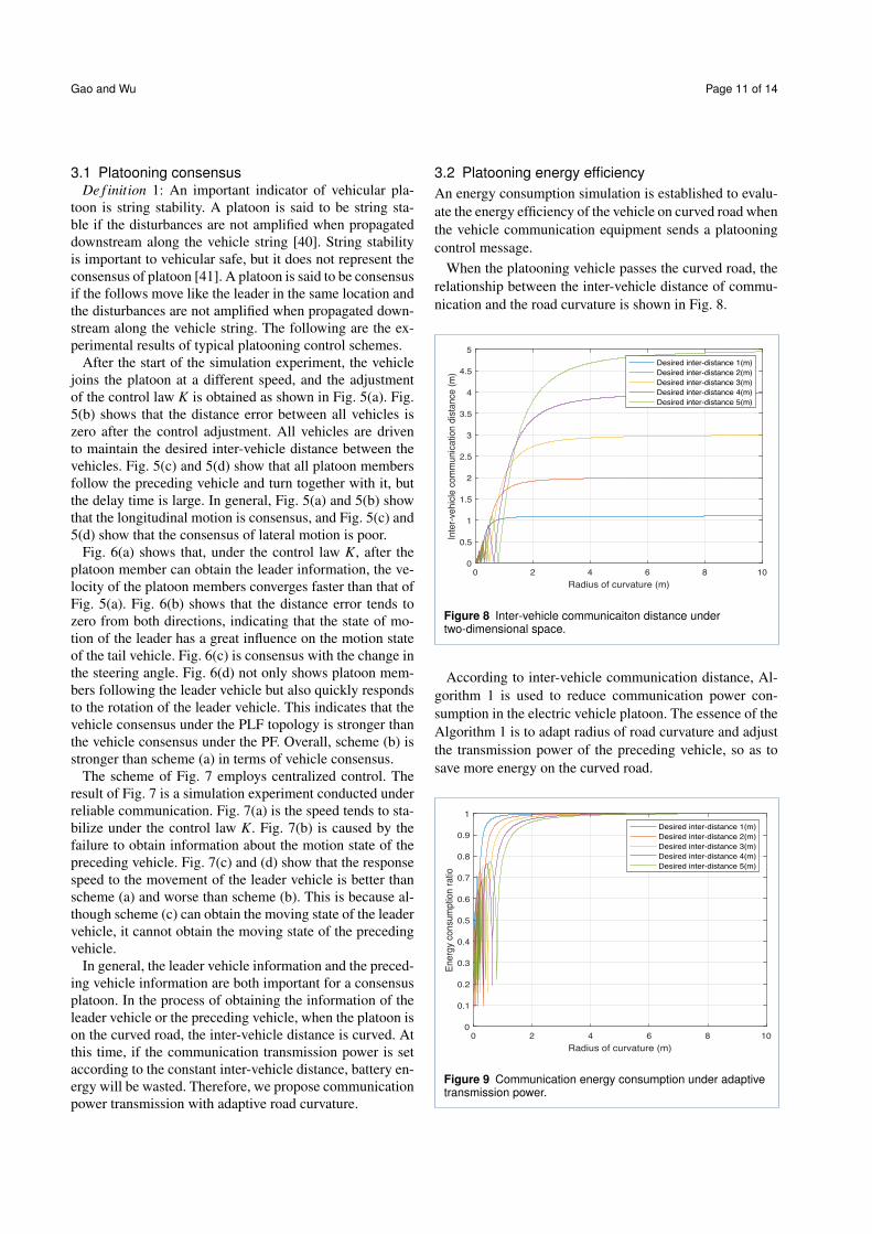
3.2 Platooning energy efficiency
An energy consumption simulation is established to evalu-
ate the energy efficiency of the vehicle on curved road when
the vehicle communication equipment sends a platooning
control message.
When the platooning vehicle passes the curved road, the
relationship between the inter-vehicle distance of commu-
nication and the road curvature is shown in Fig. 8.
0 2 4 6 8 10
Radius of curvature (m)
0
0.5
1
1.5
2
2.5
3
3.5
4
4.5
5
Inte
r-vehic
le c
om
munic
ation d
ista
nce (
m)
Desired inter-distance 1(m)
Desired inter-distance 2(m)
Desired inter-distance 3(m)
Desired inter-distance 4(m)
Desired inter-distance 5(m)
Figure 8 Inter-vehicle communicaiton distance undertwo-dimensional space.
According to inter-vehicle communication distance, Al-
gorithm 1 is used to reduce communication power con-
sumption in the electric vehicle platoon. The essence of the
Algorithm 1 is to adapt radius of road curvature and adjust
the transmission power of the preceding vehicle, so as to
save more energy on the curved road.
0 2 4 6 8 10
Radius of curvature (m)
0
0.1
0.2
0.3
0.4
0.5
0.6
0.7
0.8
0.9
1
En
erg
y co
nsu
mp
tion
ra
tio
Desired inter-distance 1(m)
Desired inter-distance 2(m)
Desired inter-distance 3(m)
Desired inter-distance 4(m)
Desired inter-distance 5(m)
Figure 9 Communication energy consumption under adaptivetransmission power.
Gao and Wu Page 12 of 14
On the straight road, the minimum transmission power
of preceding vehicles is calculated by path loss equation
(12b). When the platooning enters the curved road, the
inter-vehicle communication distance of platooning is un-
equal to the desired inter-vehicle distance. Relative to the
minimum transmitted power of vehicles on the straight
road, the energy consumption ratio on the curved road is
shown in Fig. 9. Simulation results show that the bigger de-
sired inter-vehicle distance, the more power is saved under
Algorithm 1. However, the bigger inter-vehicle distance,
the worse aerodynamic performance of platoon members.
According to a two-car queue measured by University of
Southern California scholars in the Dryden Wind Tunnel,
when the inter-vehicle distance is 0-5m, the actual wind
resistance coefficient of the rear vehicle remains basically
unchanged and remains at a low level [42]. Combined with
the analysis of Fig. 9, the electric vehicle platoon under de-
sired inter-vehicle distance 5m can save 5.3% of the energy
of the communication system.
0 1 2 3 4 5 6 7 8 9 10
Radius of curvature (m)
0
0.2
0.4
0.6
0.8
1
1.2
Energ
y c
onsum
ption r
atio Adaptive radius of curvature
Maximum radius of curvature
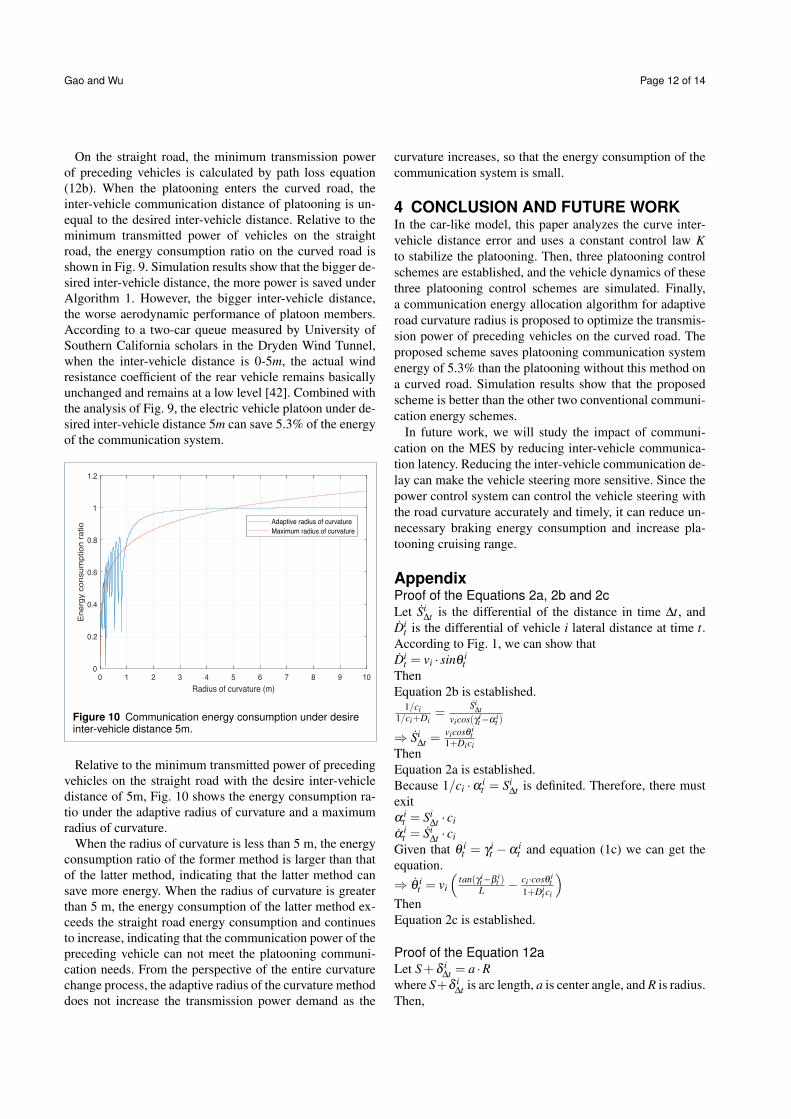
Figure 10 Communication energy consumption under desireinter-vehicle distance 5m.
Relative to the minimum transmitted power of preceding
vehicles on the straight road with the desire inter-vehicle
distance of 5m, Fig. 10 shows the energy consumption ra-
tio under the adaptive radius of curvature and a maximum
radius of curvature.
When the radius of curvature is less than 5 m, the energy
consumption ratio of the former method is larger than that
of the latter method, indicating that the latter method can
save more energy. When the radius of curvature is greater
than 5 m, the energy consumption of the latter method ex-
ceeds the straight road energy consumption and continues
to increase, indicating that the communication power of the
preceding vehicle can not meet the platooning communi-
cation needs. From the perspective of the entire curvature
change process, the adaptive radius of the curvature method
does not increase the transmission power demand as the
curvature increases, so that the energy consumption of the
communication system is small.
4 CONCLUSION AND FUTURE WORKIn the car-like model, this paper analyzes the curve inter-
vehicle distance error and uses a constant control law K
to stabilize the platooning. Then, three platooning control
schemes are established, and the vehicle dynamics of these
three platooning control schemes are simulated. Finally,
a communication energy allocation algorithm for adaptive
road curvature radius is proposed to optimize the transmis-
sion power of preceding vehicles on the curved road. The
proposed scheme saves platooning communication system
energy of 5.3% than the platooning without this method on
a curved road. Simulation results show that the proposed
scheme is better than the other two conventional communi-
cation energy schemes.
In future work, we will study the impact of communi-
cation on the MES by reducing inter-vehicle communica-
tion latency. Reducing the inter-vehicle communication de-
lay can make the vehicle steering more sensitive. Since the
power control system can control the vehicle steering with
the road curvature accurately and timely, it can reduce un-
necessary braking energy consumption and increase pla-
tooning cruising range.
AppendixProof of the Equations 2a, 2b and 2c
Let Si∆t is the differential of the distance in time ∆t, and
Dit is the differential of vehicle i lateral distance at time t.
According to Fig. 1, we can show that
Dit = vi · sinθ i
t
Then
Equation 2b is established.1/ci
1/ci+Di=
Si∆t
vicos(γ it−α i
t )
⇒ Si∆t =
vicosθ it
1+Dici
Then
Equation 2a is established.
Because 1/ci ·αit = Si
∆t is definited. Therefore, there must
exit
α it = Si
∆t · ci
α it = Si
∆t · ci
Given that θ it = γ i
t −α it and equation (1c) we can get the
equation.
⇒ θ it = vi
⇣
tan(γ it−β i
t )L
−ci·cosθ i
t
1+Dit ci
⌘
Then
Equation 2c is established.
Proof of the Equation 12a
Let S+δ i∆t = a ·R
where S+δ i∆t is arc length, a is center angle, and R is radius.
Then,

Gao and Wu Page 13 of 14
sin(a/2) = (d/2)/R
so, d = 2R · sin(a/2)Now,
a = (S+δ i∆t)/R and R = 1/ci
Hence,
d = 2ci· sin
⇣
(S+δ i∆t )·ci
2
⌘
.
Abbreviations
MES:main energy systems; AES:auxiliary energy systems; MATLAB:matrix
laboratory; EVs: electric vehicles; V2V: vehicle to vehicle;
1-D:one-dimensional; PF:predecessor-following; PLF: predecessor- leader
following; BD:bidirectional; BDL:bidirectional-leader; TPF:two-predecessors
following; TPLF:two-predecessor-leader following; OBU:On board Unit;
TPC:transmit power control;
Acknowledgements
This research was supported in part by The Okawa Foundation for
Information and Telecommunications, in part by G-7 Scholarship
Foundation, in part by JSPS KAKENHI grant numbers 18KK0279,
19H04093, 20H00592, and 21H03424.
Funding
This work was supported in part by China Scholarship Council.
Availability of data and materials
All data of simulation and experiment can be obtained by contacting the
authors of the paper.
Competing interests
The authors declare that they have no competing interests.
Authors’ contributions
Both authors in the paper have equal contributions from the idea to the
completion of the paper.
Authors’ information
Wei Gao is currently pursuing the Ph.D. degree with the State Key
Laboratory of Networking and Switch- ing Technology, Beijing University of
Posts and Telecommunications, Beijing, China. His research interests are in
the areas of multi-vehicle platoon formation control, and vehicle
communication.
Celimuge Wu ([email protected]) received his M.E. degree from Beijing
Institute of Technology, Beijing, China, in 2006, and PhD degree from the
University of Electro-Communications, Tokyo, Japan, in 2010. He was an
assistant professor at the Graduate School of Information Systems, the
University of Electro-Communications from 2010, and since November
2015, he has been an associate professor at the same university. He current
research interests include vehicular networks, edge Comput- ing, and
intelligent transport systems.
Author details1Beijing University of Posts and Telecommunications Beijing, the State Key
Laboratory of Networking and Switching Technology, Beijing, China. 2the
Department of Computer and Network Engineering, The University of
Electro-Communications 1-5-1, Chofugaoka, Tokyo, Japan.
References
1. Ortuzar, M., Moreno, J., Dixon, J.: Ultracapacitor-based auxiliary
energy system for an electric vehicle: Implementation and evaluation.
IEEE Transactions on Industrial Electronics 54(4), 2147–2156 (2007).
doi:10.1109/TIE.2007.894713
2. Massera Filho, C., Terra, M.H., Wolf, D.F.: Safe optimization of highway
traffic with robust model predictive control-based cooperative adaptive
cruise control. IEEE Transactions on Intelligent Transportation Systems
18(11), 3193–3203 (2017). doi:10.1109/TITS.2017.2679098
3. 3GPP: 3rd generation partner ship project 22.886; technical
specification group services and system aspects; study on
enhancement of 3gpp support for 5g v2x services (v16.2.0, release
16). (2018)
4. Jia, D., Lu, K., Wang, J., Zhang, X., Shen, X.: A survey on
platoon-based vehicular cyber-physical systems. IEEE
Communications Surveys Tutorials 18(1), 263–284 (2016).
doi:10.1109/COMST.2015.2410831
5. Zheng, Y., Li, S.E., Li, K., Ren, W.: Platooning of connected vehicles
with undirected topologies: Robustness analysis and distributed
h-infinity controller synthesis. IEEE Transactions on Intelligent
Transportation Systems 19(5), 1353–1364 (2018).
doi:10.1109/TITS.2017.2726038
6. Li, S.E., Qin, X., Zheng, Y., Wang, J., Li, K., Zhang, H.: Distributed
platoon control under topologies with complex eigenvalues: Stability
analysis and controller synthesis. IEEE Transactions on Control
Systems Technology 27(1), 206–220 (2019).
doi:10.1109/TCST.2017.2768041
7. Seiler, P., Raja Sengupta: An h/sub /spl infin// approach to networked
control. IEEE Transactions on Automatic Control 50(3), 356–364
(2005). doi:10.1109/TAC.2005.844177
8. Thibault, L., De Nunzio, G., Sciarretta, A.: A unified approach for
electric vehicles range maximization via eco-routing, eco-driving, and
energy consumption prediction. IEEE Transactions on Intelligent
Vehicles 3(4), 463–475 (2018). doi:10.1109/TIV.2018.2873922
9. Zhang, S., Luo, Y., Wang, J., Wang, X., Li, K.: Predictive energy
management strategy for fully electric vehicles based on preceding
vehicle movement. IEEE Transactions on Intelligent Transportation
Systems 18(11), 3049–3060 (2017). doi:10.1109/TITS.2017.2672542
10. Xu, W., Chen, H., Wang, J., Zhao, H.: Velocity optimization for braking
energy management of in-wheel motor electric vehicles. IEEE Access
7, 66410–66422 (2019). doi:10.1109/ACCESS.2019.2915102
11. Kachroudi, S., Grossard, M., Abroug, N.: Predictive driving guidance of
full electric vehicles using particle swarm optimization. IEEE
Transactions on Vehicular Technology 61(9), 3909–3919 (2012).
doi:10.1109/TVT.2012.2212735
12. Jin, C., Sheng, X., Ghosh, P.: Optimized electric vehicle charging with
intermittent renewable energy sources. IEEE Journal of Selected
Topics in Signal Processing 8(6), 1063–1072 (2014).
doi:10.1109/JSTSP.2014.2336624
13. Khalifa, A., Kermorgant, O., Dominguez, S., Martinet, P.: Platooning of
car-like vehicles in urban environments: An observer-based approach
considering actuator dynamics and time delays. IEEE Transactions on
Intelligent Transportation Systems, 1–13 (2020)
14. Godbole, D.N., Lygeros, J.: Longitudinal control of the lead car of a
platoon. IEEE Transactions on Vehicular Technology 43(4), 1125–1135
(1994)
15. Wei, S., Zou, Y., Zhang, X., Zhang, T., Li, X.: An integrated longitudinal
and lateral vehicle following control system with radar and
vehicle-to-vehicle communication. IEEE Transactions on Vehicular
Technology 68(2), 1116–1127 (2019)
16. Bayuwindra, A., Ploeg, J., Lefeber, E., Nijmeijer, H.: Combined
longitudinal and lateral control of car-like vehicle platooning with
extended look-ahead. IEEE Transactions on Control Systems
Technology 28(3), 790–803 (2020)
17. Ghasemi, A., Kazemi, R., Azadi, S.: Stable decentralized control of a
platoon of vehicles with heterogeneous information feedback. IEEE
Transactions on Vehicular Technology 62(9), 4299–4308 (2013)
18. Yadlapalli, S.K., Darbha, S., Rajagopal, K.R.: Information flow and its
relation to stability of the motion of vehicles in a rigid formation. IEEE
Transactions on Automatic Control 51(8), 1315–1319 (2006)
19. Sadraddini, S., Sivaranjani, S., Gupta, V., Belta, C.: Provably safe
cruise control of vehicular platoons. IEEE Control Systems Letters 1(2),
262–267 (2017)
20. Chehardoli, H., Ghasemi, A.: Adaptive centralized/decentralized control
and identification of 1-d heterogeneous vehicular platoons based on
constant time headway policy. IEEE Transactions on Intelligent
Transportation Systems 19(10), 3376–3386 (2018).
doi:10.1109/TITS.2017.2781152
21. Wu, H.-x., Cheng, S.-k., Cui, S.-m.: Communication of vehicle
management unit in the electric vehicle. IEEE Transactions on
Magnetics 41(1), 514–517 (2005). doi:10.1109/TMAG.2004.839273
22. Zander, J.: Performance of optimum transmitter power control in
cellular radio systems. IEEE Transactions on Vehicular Technology
41(1), 57–62 (1992). doi:10.1109/25.120145

Gao and Wu Page 14 of 14
23. Grandhi, S.A., Vijayan, R., Goodman, D.J., Zander, J.: Centralized
power control in cellular radio systems. IEEE Transactions on Vehicular
Technology 42(4), 466–468 (1993). doi:10.1109/25.260766
24. Rosberg, Z., Zander, J.: Toward a framework for power control in
cellular systems. Wireless Networks 4(4), 215–222 (1998)
25. Sommer, C.: Veins. The open source vehicular network simulation
framework (2006-2020)
26. Segata, M.: Plexe. The Platooning Extension for Veins (2014-2018)
27. Li, S.E., Zheng, Y., Li, K., Wang, J.: An overview of vehicular platoon
control under the four-component framework. In: 2015 IEEE Intelligent
Vehicles Symposium (IV), pp. 286–291 (2015).
doi:10.1109/IVS.2015.7225700
28. Hao, H., Barooah, P., Mehta, P.G.: Stability margin scaling laws for
distributed formation control as a function of network structure. IEEE
Transactions on Automatic Control 56(4), 923–929 (2011).
doi:10.1109/TAC.2010.2103416
29. Peng, J.Z.: Range policy of adaptive cruise control vehicles for
improved flow stability and string stability. IEEE Transactions on
Intelligent Transportation Systems 6(2), 229–237 (2005).
doi:10.1109/TITS.2005.848359
30. Liang, C., Peng, H.: Optimal adaptive cruise control with guaranteed
string stability. VEHICLE SYSTEM DYNAMICS 32(4-5), 313–330
(1999). doi:10.1076/vesd.32.4.313.208
31. Zheng, Y., Eben Li, S., Wang, J., Cao, D., Li, K.: Stability and scalability
of homogeneous vehicular platoon: Study on the influence of
information flow topologies. IEEE Transactions on Intelligent
Transportation Systems 17(1), 14–26 (2016).
doi:10.1109/TITS.2015.2402153
32. Li, S.E., Zheng, Y., Li, K., Wu, Y., Hedrick, J.K., Gao, F., Zhang, H.:
Dynamical modeling and distributed control of connected and
automated vehicles: Challenges and opportunities. IEEE Intelligent
Transportation Systems Magazine 9(3), 46–58 (2017).
doi:10.1109/MITS.2017.2709781
33. Rajamani, R., Han-Shue Tan, Boon Kait Law, Wei-Bin Zhang:
Demonstration of integrated longitudinal and lateral control for the
operation of automated vehicles in platoons. IEEE Transactions on
Control Systems Technology 8(4), 695–708 (2000).
doi:10.1109/87.852914
34. Ali, A.: Modeling and control of a platoon of urban autonomous
vehicles. PhD thesis, :Research Institute in Communications and
Cybernetics of Nantes (IRCCyN ) (2015)
35. M. Segata, H.M.C. T. R. Li: Safe and efficient communication protocols
for platoon control. PhD Thesis (Dissertation) University of Innsbruck
(2016)
36. Segata, M., Joerer, S., Bloessl, B., Sommer, C., Dressler, F., Cigno,
R.L.: Plexe: A platooning extension for veins. In: 2014 IEEE Vehicular
Networking Conference (VNC), pp. 53–60 (2014).
doi:10.1109/VNC.2014.7013309
37. Wang, S..D.W..v.A.B..S.B. M ; Hoogendoorn: Delay-compensating
strategy to enhance string stability of adaptive cruise controlled
vehicles. TRANSPORTMETRICA B-TRANSPORT DYNAMICS 6(3),
211–229 (2018). doi:10.1080/21680566.2016.1266973
38. Wei, L., Hu, R.Q., Qian, Y., Wu, G.: Energy efficiency and spectrum
efficiency of multihop device-to-device communications underlaying
cellular networks. IEEE Transactions on Vehicular Technology 65(1),
367–380 (2016). doi:10.1109/TVT.2015.2389823
39. 3GPP: 3rd generation partnership project 38.901; technical
specification group radio access network; study on channel model for
frequencies from 0.5 to 100 ghz (release 16). (2019)
40. Swaroop, D., Hedrick, J.K.: String stability of interconnected systems.
In: Proceedings of 1995 American Control Conference - ACC’95, vol. 3,
pp. 1806–18103 (1995). doi:10.1109/ACC.1995.531196
41. Santini, S., Salvi, A., Valente, A.S., PescapsS, A., Segata, M., Lo
Cigno, R.: A consensus-based approach for platooning with
intervehicular communications and its validation in realistic scenarios.
IEEE Transactions on Vehicular Technology 66(3), 1985–1999 (2017).
doi:10.1109/TVT.2016.2585018
42. Hammache, M., Michaelian, M., Browand, F.: Aerodynamic forces on
truck models including two trucks in tandem. SAE Paper 1(0530)
(2002)